WO2023090464A2 - 両面テープ及びテープカッター - Google Patents
両面テープ及びテープカッター Download PDFInfo
- Publication number
- WO2023090464A2 WO2023090464A2 PCT/JP2023/012113 JP2023012113W WO2023090464A2 WO 2023090464 A2 WO2023090464 A2 WO 2023090464A2 JP 2023012113 W JP2023012113 W JP 2023012113W WO 2023090464 A2 WO2023090464 A2 WO 2023090464A2
- Authority
- WO
- WIPO (PCT)
- Prior art keywords
- tape
- double
- side plate
- tape cutter
- cutter
- Prior art date
Links
- 239000000853 adhesive Substances 0.000 claims abstract description 28
- 230000001070 adhesive effect Effects 0.000 claims abstract description 28
- 238000005520 cutting process Methods 0.000 claims description 61
- 239000000463 material Substances 0.000 claims description 21
- 238000003780 insertion Methods 0.000 description 24
- 230000037431 insertion Effects 0.000 description 24
- 210000000078 claw Anatomy 0.000 description 10
- 238000004804 winding Methods 0.000 description 7
- 230000002093 peripheral effect Effects 0.000 description 3
- 230000007423 decrease Effects 0.000 description 2
- 230000000694 effects Effects 0.000 description 2
- 238000004519 manufacturing process Methods 0.000 description 2
- 239000002184 metal Substances 0.000 description 2
- 229920003023 plastic Polymers 0.000 description 2
- 239000004033 plastic Substances 0.000 description 2
- 238000003825 pressing Methods 0.000 description 2
- 239000002699 waste material Substances 0.000 description 2
- 229920000704 biodegradable plastic Polymers 0.000 description 1
- 229920002678 cellulose Polymers 0.000 description 1
- 239000001913 cellulose Substances 0.000 description 1
- 239000011248 coating agent Substances 0.000 description 1
- 238000000576 coating method Methods 0.000 description 1
- 239000000428 dust Substances 0.000 description 1
- 238000012986 modification Methods 0.000 description 1
- 230000004048 modification Effects 0.000 description 1
- 239000002121 nanofiber Substances 0.000 description 1
- 239000000123 paper Substances 0.000 description 1
- 239000011347 resin Substances 0.000 description 1
- 229920005989 resin Polymers 0.000 description 1
- 239000002023 wood Substances 0.000 description 1
Images


Classifications
-
- B—PERFORMING OPERATIONS; TRANSPORTING
- B65—CONVEYING; PACKING; STORING; HANDLING THIN OR FILAMENTARY MATERIAL
- B65H—HANDLING THIN OR FILAMENTARY MATERIAL, e.g. SHEETS, WEBS, CABLES
- B65H35/00—Delivering articles from cutting or line-perforating machines; Article or web delivery apparatus incorporating cutting or line-perforating devices, e.g. adhesive tape dispensers
- B65H35/0006—Article or web delivery apparatus incorporating cutting or line-perforating devices
-
- C—CHEMISTRY; METALLURGY
- C09—DYES; PAINTS; POLISHES; NATURAL RESINS; ADHESIVES; COMPOSITIONS NOT OTHERWISE PROVIDED FOR; APPLICATIONS OF MATERIALS NOT OTHERWISE PROVIDED FOR
- C09J—ADHESIVES; NON-MECHANICAL ASPECTS OF ADHESIVE PROCESSES IN GENERAL; ADHESIVE PROCESSES NOT PROVIDED FOR ELSEWHERE; USE OF MATERIALS AS ADHESIVES
- C09J7/00—Adhesives in the form of films or foils
- C09J7/30—Adhesives in the form of films or foils characterised by the adhesive composition
- C09J7/38—Pressure-sensitive adhesives [PSA]
-
- C—CHEMISTRY; METALLURGY
- C09—DYES; PAINTS; POLISHES; NATURAL RESINS; ADHESIVES; COMPOSITIONS NOT OTHERWISE PROVIDED FOR; APPLICATIONS OF MATERIALS NOT OTHERWISE PROVIDED FOR
- C09J—ADHESIVES; NON-MECHANICAL ASPECTS OF ADHESIVE PROCESSES IN GENERAL; ADHESIVE PROCESSES NOT PROVIDED FOR ELSEWHERE; USE OF MATERIALS AS ADHESIVES
- C09J7/00—Adhesives in the form of films or foils
- C09J7/40—Adhesives in the form of films or foils characterised by release liners
Definitions
- Patent Document 1 As a conventional double-sided tape, there is one described in Patent Document 1, for example.
- the double-faced tape described in the document is wound around an annular core. Both the front and back sides of the double-sided tape are adhesive surfaces. However, a release paper is attached to the surface of the double-sided tape. Therefore, the adhesive surface is exposed only on the back surface of the double-sided tape.
- This double-sided tape is used while being rotatably held by a tape cutter.
- the tape cutter has a pair of side plate portions (face plates), a bottom plate portion, and a cutting blade.
- the pair of side plate portions covers the double-sided tape from both sides.
- the bottom plate portion is connected to the lower ends of the side plate portions so as to connect the side plate portions.
- a cutting blade is provided at the end of the bottom plate portion.
- the present invention has been made in view of the above problems, and an object of the present invention is to provide a double-sided tape that contributes to reducing the amount of release paper discharged, and a tape cutter equipped with the same.
- a tape cutter according to the present invention is a tape cutter used for feeding and cutting the double-sided tape, and is characterized in that the double-sided tape is rotatably held.
- a double-sided tape that contributes to reducing the amount of release paper discharged and a tape cutter provided with the same are realized.
- FIG. 2 is a plan view showing a lead-out portion 1b of the double-sided tape of FIG. 1; It is a bottom view which shows the drawer part 1b of the double-sided tape of FIG.
- FIG. 3 is a cross-sectional view taken along line IV-IV of FIG. 2;
- 1 is a perspective view showing a first embodiment of a tape cutter according to the invention;
- FIG. Figure 6 is a side view of the tape cutter of Figure 5; 6 is a front view of the tape cutter of FIG. 5;
- FIG. Figure 6 is an end view of the tape cutter of Figure 5;
- FIG. 6 is a side view for explaining an example of how to use the tape cutter of FIG. 5;
- FIG. 1 is a perspective view showing a first embodiment of a tape cutter according to the invention
- FIG. Figure 6 is a side view of the tape cutter of Figure 5;
- 6 is a front view of the tape cutter of FIG. 5;
- FIG. Figure 6 is an end view of the tape cutter of Figure 5;
- FIG. 6 is a side view for explaining an example of how to use the tape cutter of FIG. 5;
- FIG. 6 is a side view for explaining an example of how to use the tape cutter of FIG. 5;
- FIG. 4 is a perspective view showing a second embodiment of a tape cutter according to the invention;
- Figure 13 is a side view of the tape cutter of Figure 12; 13 is a front view of the tape cutter of FIG. 12;
- FIG. FIG. 13 is a plan view showing the tape cutter of FIG. 12;
- Figure 13 is an end view of the tape cutter of Figure 12;
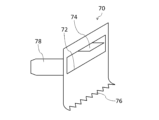
- 4 is a perspective view showing a guide portion 70;
- FIG. 13 is an end view for explaining an example of how to use the tape cutter of FIG. 12;
- FIG. 13 is an end view for explaining an example of how to use the tape cutter of FIG. 12;
- FIG. 10 is a plan view for explaining a modified example of the release paper 20;
- FIG. 11 is a plan view for explaining another modified example of the release paper 20;
- FIG. 1 is a side view showing one embodiment of the double-sided tape according to the present invention.
- the double-sided tape 1 is wound around an annular core 90 .
- the double-sided tape 1 consists of a winding portion 1a and a lead-out portion 1b.
- the wound portion 1a is a portion of the double-sided tape 1 wound around the core 90, and has an annular shape as a whole.
- the pull-out portion 1b is a portion of the double-sided tape 1 pulled out from the winding portion 1a.
- the double-sided tape 1 has a tape body 10 and a release paper 20 .
- the tape body 10 has a front surface 12 (first surface) and a back surface 14 (second surface). Both the front surface 12 and the back surface 14 are adhesive surfaces. In this embodiment, the entire front surface 12 is an adhesive surface, and the entire back surface 14 is also an adhesive surface.
- the release paper 20 is attached to the surface 12 of the tape body 10 .
- Release paper 20 is applied to only a portion of surface 12 . That is, the release paper 20 is attached only to a part of the adhesive surface of the surface 12 .
- the release paper 20 is attached only to a portion of the surface 12 in the width direction of the tape body 10 (vertical direction in FIGS. 2 and 3).
- the width direction of the tape body 10 is a direction perpendicular to the extending direction of the tape body 10 (horizontal direction in FIGS. 2 and 3). Therefore, the width w1 of the release paper 20 is smaller than the width w2 of the tape body .
- the width w1 is preferably 20% or more and 50% or less of the width w2.
- the center line C1 of the release paper 20 coincides with the center line C2 of the tape body 10.
- the center line C1 and the center line C2 are imaginary straight lines that bisect the release paper 20 and the tape body 10 in the width direction, respectively.
- the release paper 20 is continuously attached to the surface 12 in the extending direction of the tape body 10 . That is, the release paper 20 is attached to the entire surface 12 in the extending direction of the tape body 10 .
- the tape cutter 6 is used to pay out and cut the double-sided tape 1 .
- the double-sided tape 1 is rotatably held by the tape cutter 6 . 5 to 7, illustration of the double-sided tape 1 is omitted.
- the tape cutter 6 includes a pair of side plate portions 30 , a bottom plate portion 40 , a cutting blade 50 and an adhering portion 60 .
- a pair of side plate portions 30 covers the double-sided tape 1 from both sides.
- FIG. 8 shows an end surface that is parallel to the side plate portions 30 and positioned between the pair of side plate portions 30 .
- a lower portion of each side plate portion 30 (in a side view, a portion below a straight line including an insertion portion 32 described later) is rectangular.
- the upper portion of each side plate portion 30 (the portion above the straight line in side view) has a semicircular shape.
- the side plate portion 30 may cover the entire double-sided tape 1 from the side, or may cover only a portion thereof.
- the side plate portion 30 may overlap the entire double-sided tape 1 or may overlap only a portion of the double-sided tape 1 when viewed from the side.
- Each side plate portion 30 has a plate shape.
- a material for the side plate portion 30 for example, paper, plastic, metal, or wood can be used. Papers also include processed papers and cellulose nanofibers (CNF).
- the plastic may be a biodegradable plastic.
- An insertion portion 32 is connected to each side plate portion 30 .
- the insertion part 32 is inserted inside the core 90 of the double-sided tape 1 so that the double-sided tape 1 does not come off the tape cutter 6 .
- the insertion portion 32 has a plate shape.
- the thickness direction of the insertion portion 32 is perpendicular to the thickness direction of the side plate portion 30 .
- the two insertion portions 32 are fixed to each other in an overlapping state. Thereby, the center portions of the pair of side plate portions 30 are connected by the insertion portion 32 .
- the “central portion” is a portion of the side plate portion 30 other than the peripheral edge.
- Each insertion portion 32 is preferably formed integrally with the side plate portion 30 .
- the bottom plate portion 40 is connected to the lower end 30 a of each side plate portion 30 . Thereby, the lower ends 30 a of the pair of side plate portions 30 are connected by the bottom plate portion 40 .
- the bottom plate portion 40 may be connected to the entire lower end 30a of each side plate portion 30, or may be connected to only a portion thereof.
- the bottom plate portion 40 has a plate shape.
- the thickness direction of the bottom plate portion 40 is perpendicular to the thickness direction of the side plate portion 30 and equal to the thickness direction of the insertion portion 32 .
- the bottom plate portion 40 is preferably formed integrally with the side plate portion 30 .
- the material of the bottom plate portion 40 may be the same as or different from that of the side plate portion 30 .
- the cutting blade 50 is provided at the end of the bottom plate portion 40 .
- the cutting blade 50 is fixed on the bottom plate portion 40 .
- the cutting blade 50 cuts the double-sided tape 1 while in contact with the front surface 12 side (the release paper 20 ) of the tape body 10 .
- the tip of the cutting blade 50 protrudes from the bottom plate portion 40 .
- the tip of the cutting blade 50 is separated from the winding portion 1a.
- the cutting blade 50 cuts the double-sided tape 1 leaving a fixed length of the drawn-out portion 1b.
- the material of the cutting blade 50 may be the same as or different from the material of the side plate portion 30 .
- the cutting blade 50 may be formed integrally with the bottom plate portion 40 .
- the sticking part 60 is provided above the cutting blade 50 .
- the back surface 14 of the tape body 10 is attached to the attaching portion 60 with the end 1 c of the double-sided tape 1 (the lead-out portion 1 b ) floating from the cutting blade 50 .
- the rear surface 14 is attached to the tip portion 62 of the attachment portion 60 .
- the tip portion 62 is equal to the lower end of the sticking portion 60 .
- the tip portion 62 (the portion with which the back surface 14 contacts) may be flat or uneven.
- the width of the adhering portion 60 monotonously decreases toward the tip portion 62 .
- the width w3 (see FIG. 7) of the tip portion 62 is smaller than the width w2 of the tape body 10. As shown in FIG.
- the width w3 is preferably 50% or less of the width w2, more preferably 20% or less.
- the sticking portion 60 is connected to each side plate portion 30 .
- the sticking portion 60 is connected to the side end 30 b of each side plate portion 30 .
- the side end 30b is a portion of the peripheral edge of the side plate portion 30 other than the lower end 30a located at the lower portion.
- the side end 30b is linear.
- the side ends 30b of the pair of side plate portions 30 are connected by the sticking portion 60.
- the side ends 30b of the pair of side plate portions 30 are connected to each other only by the sticking portion 60.
- the side ends 30b of the pair of side plate portions 30 are not connected to each other on the opposite side of the sticking portion 60.
- the distance d1 (see FIG. 7) from the cutting blade 50 to the sticking portion 60 (tip portion 62) in the vertical direction is preferably equal to or greater than the interval d2 between the pair of side plate portions 30.
- the vertical direction is equal to the thickness direction of the bottom plate portion 40 (the vertical direction in FIGS. 5 to 7).
- the distance d1 is preferably 10 mm or more, more preferably 15 mm or more.
- the sticking portion 60 may be detachable with respect to the pair of side plate portions 30, or may not be detachable.
- detachable means that attachment and detachment of the sticking portion 60 to the side plate portion 30 can be repeated without damaging the side plate portion 30 and the sticking portion 60 .
- the tip portion 62 is located on the side end 30b of the side plate portion 30 when viewed from the side. In plan view, the tip portion 62 may or may not overlap the tip of the cutting blade 50 . That is, the tip portion 62 may be positioned directly above the tip of the cutting blade 50 or may be positioned obliquely above it. In the latter case, the distance (horizontal distance) from the tip of the cutting blade 50 to the tip 62 in plan view is preferably smaller than the distance d1.
- the sticking portion 60 has a plate shape.
- the thickness direction of the sticking portion 60 is perpendicular to both the thickness direction of the side plate portion 30 and the thickness direction of the bottom plate portion 40 .
- the thickness of the sticking portion 60 is preferably equal to the thickness of each side plate portion 30 .
- the sticking portion 60 may be formed integrally with the side plate portion 30 .
- the material of the sticking portion 60 may be the same as or different from the material of the side plate portion 30 .
- the double-sided tape 1 (drawer portion 1 b ) is pinched with fingers to peel off the double-sided tape 1 from the sticking portion 60 and then pulled along the bottom plate portion 40 .
- the double-faced tape 1 is fed out from between the bottom plate portion 40 and the sticking portion 60 .
- the double-sided tape 1 is cut by pressing the surface 12 of the tape body 10 and the release paper 20 against the tip of the cutting blade 50 .
- the back surface 14 of the tape body 10 is adhered to the adhered portion 60 again.
- the end 1c of the double-sided tape 1 protrudes from the tip portion 62.
- the drawer portion 1b is adhered only to the adhered portion 60.
- the tape cutter 6 is configured so that the lead-out portion 1b is not adhered to a portion of the tape cutter 6 other than the adhered portion 60.
- the double-sided tape 1 can be fed out from the tape cutter 6 to obtain a cut piece of desired length.
- the double-sided tape 1 is provided with a tape body 10 in which both the front surface 12 and the back surface 14 are adhesive surfaces.
- a release paper 20 is attached to the surface 12 of the tape body 10 .
- Release paper 20 is applied to only a portion of surface 12 .
- the double-faced tape 1 and the tape cutter 6 including the double-sided tape 1 that contribute to reduction in the amount of release paper 20 discharged are realized.
- the distance d1 is preferably equal to or greater than the interval d2 between the pair of side plate portions 30. As shown in FIG. From the same point of view, the distance d1 is preferably 10 mm or more, more preferably 15 mm or more. On the other hand, if the distance d1 is too large, it may become difficult to secure a place in the tape cutter 6 for arranging the sticking portion 60 . From this point of view, the distance d1 is preferably 50 mm or less.
- the sticking portion 60 is connected to the side end 30b of each side plate portion 30. This makes it easier to align the tip portion 62 of the sticking portion 60 with the side edge 30 b of the side plate portion 30 .
- the tip portion 62 is located on the side end 30b of the side plate portion 30 in a side view. In this case, since the tip portion 62 does not enter the space sandwiched between the pair of side plate portions 30, it is advantageous in making it easier to pick up the double-faced tape 1 attached to the attaching portion 60 with fingers.
- the width w3 of the tip portion 62 is smaller than the width w2 of the tape body 10. In this case, by changing the width w3, it is possible to adjust the contact area between the tip portion 62 and the tape body 10, and thus the adhesive force between the sticking portion 60 and the tape body 10.
- FIG. This increases options for the material of the adhering portion 60, making it easier to integrally form the adhering portion 60 with other portions (the side plate portion 30, the bottom plate portion 40, and/or the cutting blade 50).
- the width w3 may be equal to the width w2 or may be greater than the width w2.
- the width w3 may be equal to the distance d2 between the pair of side plate portions 30. As shown in FIG.
- the thickness of the sticking portion 60 is equal to the thickness of each side plate portion 30, it becomes easier to form the side plate portion 30 and the sticking portion 60 from one sheet with a uniform thickness.
- the sticking portion 60 is made of the same material as the pair of side plate portions 30 and the bottom plate portion 40, the side plate portion 30, the bottom plate portion 40 and the sticking portion 60 can be easily formed integrally.
- the manufacturing process of the tape cutter 6 can be simplified, thereby reducing the manufacturing cost of the tape cutter 6.
- FIG. 12 corresponds to a view of the tape cutter of FIG. 12 viewed from the right side.
- 16 is an end view of the tape cutter of FIG. 12.
- the tape cutter 8 has a pair of side plate portions 30 , a bottom plate portion 40 and a guide portion 70 .
- a pair of side plate portions 30 covers the double-sided tape 1 from both sides.
- FIG. 16 shows an end surface parallel to the side plate portions 30 and located between the pair of side plate portions 30 .
- the side plate portion 30 covers only a portion of the winding portion 1a of the double-sided tape 1 from the side. That is, the side plate portion 30 overlaps only a portion of the winding portion 1a in a side view.
- Each side plate portion 30 has a rectangular plate shape.
- Each side plate portion 30 is formed with a notch 38 serving as an insertion port for a claw portion 78 to be described later.
- An insertion portion 32 is connected to each side plate portion 30 .
- the insertion part 32 is inserted inside the core 90 of the double-sided tape 1 so that the double-sided tape 1 does not come off the tape cutter 8 .
- the insertion portion 32 has a plate shape.
- the thickness direction of the insertion portion 32 is perpendicular to the thickness direction of the side plate portion 30 .
- the insertion portion 32 is connected to the upper end 30 c of each side plate portion 30 .
- the two insertion portions 32 are fixed to each other in an overlapping state. Thereby, the upper ends 30 c of the pair of side plate portions 30 are connected by the insertion portion 32 .
- Each insertion portion 32 is preferably formed integrally with the side plate portion 30 .
- the material of the insertion portion 32 may be the same as or different from the material of the side plate portion 30 .
- the bottom plate portion 40 is connected to the lower end 30 a of each side plate portion 30 . Thereby, the lower ends 30 a of the pair of side plate portions 30 are connected by the bottom plate portion 40 .
- the bottom plate portion 40 may be connected to the entire lower end 30a of each side plate portion 30, or may be connected to only a portion thereof.
- the bottom plate portion 40 has a plate shape.
- the thickness direction of the bottom plate portion 40 is perpendicular to the thickness direction of the side plate portion 30 and equal to the thickness direction of the insertion portion 32 .
- the bottom plate portion 40 is preferably formed integrally with the side plate portion 30 .
- the material of the bottom plate portion 40 may be the same as or different from that of the side plate portion 30 .
- the width w4 is defined as the horizontal dimension of the sticking surface 74a.
- the width w4 is preferably 50% or less of the width w2, more preferably 20% or less.
- the cutting blade 76 cuts the drawer portion 1b that has passed through the opening 72.
- the opening 72 and the sticking portion 74 described above are provided between the winding portion 1a and the cutting blade 76 along the drawn portion 1b.
- the tip of the cutting blade 76 is directed outward (away from the side end 30b) so as to easily cut the drawn-out portion 1b.
- the tip of the cutting blade 76 protrudes from the side end 30b of the side plate portion 30 in a side view.
- the tip of the cutting blade 76 is located inside the adhering portion 74 in a side view. That is, the distance d4 (see FIG.
- the material of the cutting blade 76 may be the same as or different from the material of the other portions of the guide portion 70. In the latter case, for example, it is conceivable to use metal as the material for the cutting blade 76 and paper as the material for the other parts. Moreover, the cutting blade 76 may be formed integrally with the other portion of the guide portion 70, or may be formed separately from the other portion and then attached to the portion.
- the double-sided tape 1 is provided with a tape body 10 in which both the front surface 12 and the back surface 14 are adhesive surfaces.
- a release paper 20 is attached to the surface 12 of the tape body 10 .
- Release paper 20 is applied to only a portion of surface 12 .
- the double-sided tape 1 and the tape cutter 8 having the double-sided tape 1 that contribute to the reduction of the amount of the release paper 20 discharged are realized.
- the width w4 of the sticking portion 74 is smaller than the width w2 of the tape body 10. In this case, by changing the width w4, it is possible to adjust the contact area between the sticking portion 74 and the lead portion 1b, and thus the adhesive force between the sticking portion 74 and the lead portion 1b. As a result, it is possible to increase the options for the material of the sticking portion 74 .
- the width w4 may be equal to the width w2 or may be larger than the width w2.
- the width w4 may be equal to the length d3 of the opening 72 in the horizontal direction.
- the opening 72 overlaps the side edge 30b of the side plate portion 30 in a side view.
- the guide portion 70 is connected to the side end 30b of each side plate portion 30. This makes it easier to align the position of the opening 72 with the side edge 30 b of the side plate portion 30 .
- the present invention is not limited to the above embodiments, and various modifications are possible.
- the center line C1 of the release paper 20 coincides with the center line C2 of the tape body 10 is exemplified.
- the centerline C1 may be offset from the centerline C2, as shown in FIG. 20, for example.
- the case where the entire surface 12 of the tape body 10 is an adhesive surface is exemplified.
- only a portion of surface 12 may be an adhesive surface.
- only a portion of back surface 14 may be an adhesive surface.
- the release paper 20 is attached only to a portion of the adhesive surface of the surface 12 .
Landscapes
- Chemical & Material Sciences (AREA)
- Organic Chemistry (AREA)
- Adhesive Tapes (AREA)
- Adhesive Tape Dispensing Devices (AREA)
Abstract
剥離紙の排出量の削減に資する両面テープ、及びそれを備えるテープカッターを提供する。両面テープ1は、テープ本体10、及び剥離紙20を備えている。テープ本体10は、表面12、及び裏面14を有している。表面12及び裏面14は、何れも粘着面である。剥離紙20は、テープ本体10の表面12に貼付されている。剥離紙20は、表面12の一部にのみ貼付されている。
Description
本発明は、両面テープ、及びそれを備えるテープカッターに関する。
従来の両面テープとしては、例えば特許文献1に記載されたものがある。同文献に記載された両面テープは、円環状の芯に巻回されている。両面テープにおいては、表面及び裏面の双方が粘着面となっている。ただし、両面テープの表面には、剥離紙が貼着されている。そのため、粘着面は、両面テープの裏面にのみ露出している。この両面テープは、テープカッターに回転可能に保持された状態で使用される。テープカッターは、一対の側板部(面板)、底板部、及び切断刃を有している。一対の側板部は、両面テープを両側方から覆っている。底板部は、側板部どうしを連結するように、各側板部の下端に接続されている。切断刃は、底板部の端部に設けられている。
上述の両面テープは、一対の側板部間の隙間から繰り出されて、切断刃によって切断される。切断された両面テープ(切断片)を使用する際は、表面から剥離紙が剥離される。剥離された剥離紙は、ゴミとして排出される。このようにゴミとして排出される紙類は、リサイクルされることが望ましい。しかしながら、剥離紙は、紙とその表面をコーティングしている樹脂とを分離することができないため、リサイクルすることが困難である。そのため、SDGs(持続可能な開発目標)の観点からも、剥離紙の排出量を減らす工夫が求められる。
本発明は、上記課題に鑑みてなされたものであり、剥離紙の排出量の削減に資する両面テープ、及びそれを備えるテープカッターを提供することを目的とする。
本発明による両面テープは、粘着面である第1及び第2の面を有するテープ本体と、上記第1の面に貼付された剥離紙と、を備え、上記剥離紙は、上記第1の面の一部にのみ貼付されていることを特徴とする。
この両面テープにおいては、第1の面及び第2の面の双方が粘着面であるテープ本体が設けられている。テープ本体の第1の面には、剥離紙が貼付されている。剥離紙は、第1の面の一部にのみ貼付されている。この場合、剥離紙が第1の面の全体に貼付されている場合に比して、剥離紙の排出量を減らすことができる。
また、本発明によるテープカッターは、上記両面テープを繰り出して切断するのに用いられるテープカッターであって、上記両面テープが回転可能に保持されていることを特徴とする。
本発明によれば、剥離紙の排出量の削減に資する両面テープ、及びそれを備えるテープカッターが実現される。
以下、図面を参照しつつ、本発明の実施形態について詳細に説明する。なお、図面の説明においては、同一要素には同一符号を付し、重複する説明を省略する。
(第1実施形態)
(第1実施形態)
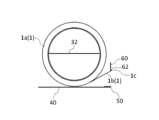
図1は、本発明による両面テープの一実施形態を示す側面図である。両面テープ1は、円環状の芯90に巻回されている。両面テープ1は、巻回部1a、及び引出部1bからなる。巻回部1aは、両面テープ1における芯90に巻回された部分であり、全体として円環状をしている。引出部1bは、両面テープ1における巻回部1aから引き出された部分である。
図2及び図3は、それぞれ、引出部1bを示す平面図及び底面図である。また、図4は、図2のIV-IV線に沿った断面図である。両面テープ1は、テープ本体10、及び剥離紙20を備えている。テープ本体10は、表面12(第1の面)、及び裏面14(第2の面)を有している。表面12及び裏面14は、何れも粘着面である。本実施形態においては、表面12の全体が粘着面であるとともに、裏面14の全体も粘着面である。
剥離紙20は、テープ本体10の表面12に貼付されている。剥離紙20は、表面12の一部にのみ貼付されている。すなわち、剥離紙20は、表面12の粘着面の一部にのみ貼付されている。剥離紙20は、テープ本体10の幅方向(図2及び図3の上下方向)について、表面12の一部にのみ貼付されている。ここで、テープ本体10の幅方向は、テープ本体10の延在方向(図2及び図3の左右方向)に垂直な方向である。それゆえ、剥離紙20の幅w1は、テープ本体10の幅w2よりも小さい。幅w1は、幅w2の20%以上50%以下であることが好ましい。これにより、テープ本体10においては、表面12の一部が剥離紙20で覆われる一方、表面12の残部及び裏面14の全体に粘着面が露出している。
剥離紙20の中心線C1は、テープ本体10の中心線C2に一致している。中心線C1及び中心線C2は、それぞれ、剥離紙20及びテープ本体10を幅方向に二等分する仮想的な直線である。剥離紙20は、テープ本体10の延在方向について、表面12に連続的に貼付されている。すなわち、剥離紙20は、テープ本体10の延在方向について、表面12の全体に貼付されている。
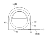
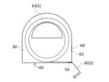
図5、図6及び図7は、それぞれ、本発明によるテープカッターの第1実施形態を示す斜視図、側面図及び正面図である。図7は、図5のテープカッターを右側から見た図に相当する。また、図8は、図5のテープカッターを示す端面図である。
テープカッター6は、両面テープ1を繰り出して切断するのに用いられる。テープカッター6において両面テープ1は、回転可能に保持されている。なお、図5乃至図7においては、両面テープ1の図示を省略している。
テープカッター6は、一対の側板部30、底板部40、切断刃50、及び貼着部60を備えている。一対の側板部30は、両面テープ1を両側方から覆っている。図8は、側板部30に平行で、かつ一対の側板部30の中間に位置する端面を示している。各側板部30の下部(側面視で、後述する挿通部32を含む直線より下の部分)は、矩形をしている。一方、各側板部30の上部(側面視で、上記直線より上の部分)は、半円状をしている。側板部30は、側方から両面テープ1の全体を覆っていてもよいし、一部のみを覆っていてもよい。すなわち、側板部30は、側面視で、両面テープ1の全体に重なっていてもよいし、一部にのみ重なっていてもよい。各側板部30は、板状をしている。側板部30の材料としては、例えば、紙類、プラスチック、金属、又は木材を用いることができる。紙類には、加工紙、及びセルロースナノファイバー(CNF)も含まれる。プラスチックは、生分解性プラスチックであってもよい。
各側板部30には、挿通部32が接続されている。挿通部32は、両面テープ1がテープカッター6から脱落しないように、両面テープ1の芯90の内側に挿通されている。挿通部32は、板状をしている。挿通部32の厚み方向は、側板部30の厚み方向に垂直である。2つの挿通部32は、重なり合った状態で互いに固定されている。これにより、一対の側板部30の中央部どうしは、挿通部32によって連結されている。ここで、「中央部」とは、側板部30の周縁以外の部分である。各挿通部32は、側板部30と一体に形成されることが好ましい。挿通部32の材料は、側板部30の材料と同一であってもよいし、異なっていてもよい。各側板部30は、半円状の開口部34を有している。開口部34は、各側板部30の上部に形成されている。開口部34は、指を挿入することが可能な大きさをしている。それゆえ、テープカッター6は、開口部34に指を入れた状態で、手に持って使用することができる。挿通部32は、開口部34の下端に接続されている。
底板部40は、各側板部30の下端30aに接続されている。これにより、一対の側板部30の下端30aどうしは、底板部40によって連結されている。底板部40は、各側板部30の下端30aの全体に接続されていてもよいし、一部にのみ接続されていてもよい。底板部40は、板状をしている。底板部40の厚み方向は、側板部30の厚み方向に垂直であり、挿通部32の厚み方向に等しい。底板部40は、側板部30と一体に形成されることが好ましい。底板部40の材料は、側板部30の材料と同一であってもよいし、異なっていてもよい。
切断刃50は、底板部40の端部に設けられている。切断刃50は、底板部40上に固定されている。切断刃50は、テープ本体10の表面12側(剥離紙20)に当接した状態で両面テープ1を切断する。切断刃50の先端は、底板部40から食み出している。切断刃50の先端は、巻回部1aから離間している。これにより、切断刃50は、一定の長さの引出部1bを残して、両面テープ1を切断する。切断刃50の材料は、側板部30の材料と同一であってもよいし、異なっていてもよい。切断刃50は、底板部40と一体に形成されてもよい。
貼着部60は、切断刃50の上方に設けられている。図8に示すように、貼着部60には、両面テープ1(引出部1b)の端1cが切断刃50から浮いた状態で、テープ本体10の裏面14が貼着される。具体的には、貼着部60の先端部62に、裏面14が貼着される。先端部62は、貼着部60の下端に等しい。先端部62(裏面14が接触する部分)は、平坦であってもよいし、凹凸が形成されていてもよい。貼着部60の幅は、先端部62に近づくにつれて単調に小さくなっている。先端部62の幅w3(図7参照)は、テープ本体10の幅w2よりも小さい。幅w3は、幅w2の50%以下であることが好ましく、20%以下であることがより好ましい。
貼着部60は、各側板部30に接続されている。具体的には、貼着部60は、各側板部30の側端30bに接続されている。側端30bは、側板部30の下端30a以外の周縁のうち、下部に位置する部分である。側端30bは、直線状をしている。これにより、一対の側板部30の側端30bどうしは、貼着部60によって連結されている。一対の側板部30の側端30bどうしは、貼着部60のみによって連結されている。それゆえ、一対の側板部30の側端30bどうしは、貼着部60の反対側においては連結されていない。また、一対の側板部30の上端30cどうしも、連結されていない。上端30cは、側板部30の下端30a以外の周縁のうち、上部に位置する部分である。上端30cは、曲線状をしている。
上下方向についての切断刃50から貼着部60(先端部62)までの距離d1(図7参照)は、一対の側板部30間の間隔d2以上であることが好ましい。上下方向は、底板部40の厚み方向(図5乃至図7の上下方向)に等しい。距離d1は、10mm以上であることが好ましく、15mm以上であることがより好ましい。貼着部60は、一対の側板部30に対して着脱自在であってもよいし、着脱自在でなくてもよい。ここで、着脱自在とは、側板部30及び貼着部60を損傷することなく、側板部30に対する貼着部60の取付け及び取外しを繰り返し行えるということである。
側面視で、先端部62は、側板部30の側端30b上に位置している。平面視で、先端部62は、切断刃50の先端に重なってもよいし、重ならなくてもよい。すなわち、先端部62は、切断刃50の先端の真上に位置してもよいし、斜め上に位置してもよい。後者の場合、平面視で切断刃50の先端から先端部62までの距離(水平方向の距離)は、距離d1よりも小さいことが好ましい。貼着部60は、板状をしている。貼着部60の厚み方向は、側板部30の厚み方向にも底板部40の厚み方向にも垂直である。貼着部60の厚みは、各側板部30の厚みに等しいことが好ましい。貼着部60は、側板部30と一体に形成されてもよい。貼着部60の材料は、側板部30の材料と同一であってもよいし、異なっていてもよい。
図9乃至図11を参照しつつ、テープカッター6の使用方法の一例を説明する。まず、図9に示すように、両面テープ1(引出部1b)を指で摘んで、両面テープ1を貼着部60から剥がした後、底板部40に沿って引っ張る。これにより、底板部40と貼着部60との間から両面テープ1が繰り出される。次に、図10に示すように、テープ本体10の表面12及び剥離紙20を切断刃50の先端に押し当てるようにして両面テープ1を切断する。その後、図11に示すように、テープ本体10の裏面14を貼着部60に再び貼着する。このとき、両面テープ1の端1cが先端部62から食み出すようにすることが好ましい。引出部1bは、貼着部60にのみ貼着される。すなわち、テープカッター6は、テープカッター6における貼着部60以外の部分に引出部1bが貼着されないように構成されている。このようにして、テープカッター6から両面テープ1を繰り出して、所望の長さの切断片を得ることができる。
本実施形態の効果を説明する。両面テープ1においては、表面12及び裏面14の双方が粘着面であるテープ本体10が設けられている。テープ本体10の表面12には、剥離紙20が貼付されている。剥離紙20は、表面12の一部にのみ貼付されている。この場合、剥離紙20が表面12の全体に貼付されている場合に比して、剥離紙20の排出量を減らすことができる。したがって、剥離紙20の排出量の削減に資する両面テープ1、及びそれを備えるテープカッター6が実現されている。
このように剥離紙20を設けることは、次の利点をもたらす。まず、テープ本体10の表面12の粘着面に触れずに両面テープ1を繰り出すことが可能となる。それにより、両面テープ1を引っ張りやすくなるとともに、表面12に指紋が付着しにくくなる。また、表面12の粘着面への塵埃の付着や、当該粘着面の粘着力の低下を抑制することができる。さらに、テープ本体10の形状が安定するため、テープ本体10が縒れにくくなる。それにより、両面テープ1を円滑に繰り出すことができる。
剥離紙20の幅w1は、テープ本体10の幅w2よりも小さい。これにより、テープ本体10の幅方向の一部にのみ剥離紙20を設けることができる。この場合、テープ本体10の延在方向の全体に剥離紙20を設けつつ、表面12の一部にのみ剥離紙20が貼付された構成を実現することができる。
剥離紙20の幅w1を小さくした方が、剥離紙20の排出量を減らすのに有利である。かかる観点から、幅w1は、テープ本体10の幅w2の50%以下であることが好ましい。他方、幅w1が小さすぎると、剥離紙20を設けることによる上述の利点を充分に享受できなくなりかねない。かかる観点から、幅w1は、幅w2の20%以上であることが好ましい。
剥離紙20の中心線C1は、テープ本体10の中心線C2に一致している。この場合、テープ本体10の幅方向について剥離紙20が偏在しないため、剥離紙20が設けられた部分を摘みながら両面テープ1を円滑に繰り出すことができる。
剥離紙20は、テープ本体10の延在方向について、表面12に連続的に貼付されている。この場合、両面テープ1の引出部1bが弛みにくくなる。これにより、引出部1bの粘着面どうしが付着してしまう事態を起こりにくくすることができる。
テープ本体10の表面12の全体が粘着面である。これにより、両面テープ1によって貼り合わせたい対象物どうしを安定的に固定することができる。
テープカッター6においては、両面テープ1が回転可能に保持されている。これにより、両面テープ1の繰出しを容易に行うことができる。
テープカッター6においては、切断刃50の上方に貼着部60が設けられている。貼着部60には、両面テープ1の端1cが切断刃50から浮いた状態で、テープ本体10の裏面14が貼着される。これにより、両面テープ1の端1cと切断刃50との間に隙間が確保されるため、両面テープ1を指で摘みやすくなる。
このように両面テープ1を貼着部60に貼着しておくことにより、両面テープ1の巻戻り(引出部1bが巻回部1aに戻ること)を起こりにくくすることができる。また、切断刃50から離れた位置で両面テープ1を摘めるため、両面テープ1を繰り出す際に指が切断刃50に触れにくくなる。このため、テープカッター6の安全性を高めることができる。
上下方向についての切断刃50から貼着部60までの距離d1が大きい方が、両面テープ1の端1cと切断刃50との隙間が広くなるため、両面テープ1を摘みやすくするのに有利である。かかる観点から、距離d1は、一対の側板部30間の間隔d2以上であることが好ましい。同様の観点から、距離d1は、10mm以上であることが好ましく、15mm以上であることがより好ましい。他方、距離d1が大きすぎると、貼着部60を配置する場所をテープカッター6に確保しにくくなりかねない。かかる観点から、距離d1は、50mm以下であることが好ましい。
貼着部60は、各側板部30に接続されている。この場合、貼着部60を、テープカッター6の形状(一対の側板部30が所定の間隔で対向した形状)を維持するための部材としても機能させることができる。
貼着部60は、各側板部30の側端30bに接続されている。これにより、貼着部60の先端部62を側板部30の側端30bに揃えやすくなる。実際、テープカッター6においては、側面視で、先端部62が側板部30の側端30b上に位置している。この場合、一対の側板部30で挟まれた空間の奥に先端部62が入り込まないため、貼着部60に貼着された両面テープ1を指で摘みやすくするのに有利である。
先端部62の幅w3は、テープ本体10の幅w2よりも小さい。この場合、幅w3を変えることにより、先端部62とテープ本体10との接触面積、ひいては貼着部60とテープ本体10との間の粘着力を調整することができる。これにより、貼着部60の材料の選択肢が増えるため、貼着部60を他の部分(側板部30、底板部40、及び/又は切断刃50)と一体に形成しやすくなる。ただし、幅w3は、幅w2に等しくてもよいし、幅w2より大きくてもよい。例えば、幅w3は、一対の側板部30間の間隔d2に等しくてもよい。
貼着部60の厚みが各側板部30の厚みに等しい場合、側板部30及び貼着部60を均一な厚みの1枚のシートから形成しやすくなる。
貼着部60が一対の側板部30及び底板部40と同一の材料からなる場合、側板部30、底板部40及び貼着部60を一体に形成しやすくなる。このように側板部30、底板部40及び貼着部60を一体に形成することにより、テープカッター6の製造工程を簡略化し、それによりテープカッター6の製造コストを削減することができる。
貼着部60が一対の側板部30に対して着脱自在である場合、貼着部60だけを新しいものと交換することが可能となる。
(第2実施形態)
(第2実施形態)
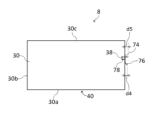
図12、図13、図14及び図15は、それぞれ、本発明によるテープカッターの第2実施形態を示す斜視図、側面図、正面図及び平面図である。図14は、図12のテープカッターを右側から見た図に相当する。また、図16は、図12のテープカッターを示す端面図である。
テープカッター8は、両面テープ1を繰り出して切断するのに用いられる。テープカッター8において両面テープ1は、回転可能に保持されている。なお、図12乃至図15においては、両面テープ1の図示を省略している。
テープカッター8は、一対の側板部30、底板部40、及び案内部70を備えている。一対の側板部30は、両面テープ1を両側方から覆っている。図16は、側板部30に平行で、かつ一対の側板部30の中間に位置する端面を示している。側板部30は、両面テープ1の巻回部1aの一部のみを側方から覆っている。すなわち、側板部30は、側面視で、巻回部1aの一部にのみ重なっている。各側板部30は、矩形の板状をしている。各側板部30には、後述する爪部78の差込口となる切込38が形成されている。
各側板部30には、挿通部32が接続されている。挿通部32は、両面テープ1がテープカッター8から脱落しないように、両面テープ1の芯90の内側に挿通されている。挿通部32は、板状をしている。挿通部32の厚み方向は、側板部30の厚み方向に垂直である。挿通部32は、各側板部30の上端30cに接続されている。2つの挿通部32は、重なり合った状態で互いに固定されている。これにより、一対の側板部30の上端30cどうしは、挿通部32によって連結されている。各挿通部32は、側板部30と一体に形成されることが好ましい。挿通部32の材料は、側板部30の材料と同一であってもよいし、異なっていてもよい。
底板部40は、各側板部30の下端30aに接続されている。これにより、一対の側板部30の下端30aどうしは、底板部40によって連結されている。底板部40は、各側板部30の下端30aの全体に接続されていてもよいし、一部にのみ接続されていてもよい。底板部40は、板状をしている。底板部40の厚み方向は、側板部30の厚み方向に垂直であり、挿通部32の厚み方向に等しい。底板部40は、側板部30と一体に形成されることが好ましい。底板部40の材料は、側板部30の材料と同一であってもよいし、異なっていてもよい。
案内部70は、一対の側板部30の側端30b間の所定の範囲内に両面テープ1の引出部1bを案内する。すなわち、案内部70は、側面視で引出部1bが側端30bと所定の範囲内で交わるように、引出部1bを案内する。案内部70は、底板部40から離間している。案内部70は、各側板部30に接続されている。具体的には、案内部70は、各側板部30の側端30bに接続されている。これにより、一対の側板部30の側端30bどうしは、案内部70によって連結されている。本実施形態において一対の側板部30の側端30bどうしは、案内部70のみによって連結されている。それゆえ、一対の側板部30の側端30bどうしは、案内部70の反対側においては連結されていない。案内部70の材料は、側板部30の材料と同一であってもよいし、異なっていてもよい。
図17は、案内部70を示す斜視図である。案内部70は、開口72、貼着部74、切断刃76、及び爪部78を有している。開口72は、両面テープ1の引出部1bが通過する部分である。開口72は、底板部40から離間している。開口72は、側面視で、側板部30の側端30bに重なっている。開口72の全体を含む平面の垂線は、側板部30の厚み方向にも底板部40の厚み方向にも垂直である。上述の「所定の範囲」は、開口72の範囲に等しい。開口72は、正面視で、横長の矩形をしている。開口72の左右方向(側板部30の厚み方向に等しい)の長さd3(図14参照)は、一対の側板部30間の間隔d2よりも小さい。長さd3は、テープ本体10の幅w2よりも大きい。
貼着部74は、開口72に連設されている。具体的には、貼着部74は、開口72の上端に連設されている。貼着部74は、開口72から一対の側板部30の外側に向かって張り出している。貼着部74には、図16に示すように、両面テープ1の引出部1bが貼着される。具体的には、貼着部74の貼着面74aに、引出部1bの裏面14が貼着される。貼着面74aは、貼着部74の下面に等しい。貼着面74aは、平面状をしている。貼着面74aは、底板部40と平行である。貼着部74の幅w4(図15参照)は、テープ本体10の幅w2よりも小さい。幅w4は、貼着面74aの左右方向の寸法として定義される。幅w4は、幅w2の50%以下であることが好ましく、20%以下であることがより好ましい。
切断刃76は、開口72を通過した引出部1bを切断する。上述の開口72及び貼着部74は、引出部1bに沿って、巻回部1aと切断刃76との間に設けられている。切断刃76の先端は、引出部1bを切断しやすいように、外向き(側端30bから遠ざかる向き)になっている。切断刃76の先端は、側面視で、側板部30の側端30bから食み出している。また、切断刃76の先端は、側面視で、貼着部74よりも内側に位置している。すなわち、切断刃76の先端から側端30bまでの距離d4(図13参照)は、貼着部74の先端から側端30bまでの距離d5よりも小さい。切断刃76の先端は、貼着部74から離間している。切断刃76の先端は、底板部40からも離間している。すなわち、側板部30の上下方向について、切断刃76の先端は、貼着部74と底板部40との間に位置している。切断刃76は、案内部70の下端に設けられている。切断刃76の幅は、テープ本体10の幅w2以上である。
切断刃76の材料は、案内部70の他の部分の材料と同一であってもよいし、異なっていてもよい。後者の場合、例えば、切断刃76の材料として金属を用いるとともに、他の部分の材料として紙類を用いることが考えられる。また、切断刃76は、案内部70の他の部分と一体に形成されてもよいし、他の部分と別々に形成された後に当該部分に取り付けられてもよい。
爪部78は、案内部70を側板部30に取り付けるための部分である。爪部78は、案内部70の両側端の各々から一対の側板部30の内側に向かって延在している。ただし、図17においては、2つの爪部78のうち片方の爪部78の図示を省略している。爪部78を側板部30の切込38に差し込むことにより、側板部30に案内部70を取り付けることができる。本実施形態において爪部78は、各側板部30の外面から内面に向かって差し込まれている。爪部78を切込38から引き抜くことにより、側板部30から案内部70を取り外すことができる。このように、案内部70は、一対の側板部30に対して着脱自在である。ここで、着脱自在とは、側板部30及び案内部70を損傷することなく、側板部30に対する案内部70の取付け及び取外しを繰り返し行えるということである。
図18及び図19を参照しつつ、テープカッター8の使用方法の一例を説明する。まず、図18に示すように、両面テープ1(引出部1b)を指で摘んで、両面テープ1を貼着部74から剥がした後、側板部30の外側に引っ張る。これにより、開口72を通して、一対の側板部30の側端30b間の隙間から両面テープ1が繰り出される。次に、図19に示すように、テープ本体10の表面12及び剥離紙20を切断刃76の先端に押し当てるようにして両面テープ1を切断する。その後、テープ本体10の裏面14を貼着部74に再び貼着する(図16参照)。このとき、両面テープ1の端1cが貼着部74の先端から食み出すようにすることが好ましい。このようにして、テープカッター8から両面テープ1を繰り出して、所望の長さの切断片を得ることができる。
本実施形態の効果を説明する。両面テープ1においては、表面12及び裏面14の双方が粘着面であるテープ本体10が設けられている。テープ本体10の表面12には、剥離紙20が貼付されている。剥離紙20は、表面12の一部にのみ貼付されている。この場合、剥離紙20が表面12の全体に貼付されている場合に比して、剥離紙20の排出量を減らすことができる。したがって、剥離紙20の排出量の削減に資する両面テープ1、及びそれを備えるテープカッター8が実現されている。
テープカッター8においては、一対の側板部30の側端30b間の所定の範囲内に両面テープ1の引出部1bを案内する案内部70が設けられている。案内部70は、底板部40から離間した開口72を有している。開口72を通過した引出部1bは、切断刃76で切断される。切断後の引出部1bは、開口72に連設された貼着部74に貼着される。これにより、引出部1bが開口72を通過した状態が維持されるため、底板部40から離間した位置で引出部1bを摘むことが可能となる。このため、繰り出す際に両面テープ1の引出部1bを摘みやすくなる。また、このように両面テープ1を貼着部74に貼着しておくことにより、両面テープ1の巻戻りを起こりにくくすることができる。
貼着部74は、開口72から一対の側板部30の外側に向かって張り出している。これにより、貼着部74が側板部30の内側に向かって張り出している場合に比して、貼着部74に貼付された引出部1bを摘みやすくなる。ただし、貼着部74は、開口72から一対の側板部30の内側に向かって張り出していてもよい。その場合、貼着部74は、一対の側板部30の間に挟まれた状態となる。
切断刃76の先端は、側面視で、貼着部74よりも内側に位置している。この場合、貼着部74に対して切断刃76が引っ込んだ状態となるため、テープカッター8の安全性を高めることができる。ただし、切断刃76の先端は、側面視で、貼着部74よりも外側に位置していてもよい。
切断刃76の先端は、貼着部74から離間している。この場合、貼着部74に貼付された引出部1bを切断刃76から離れた位置で摘めるため、両面テープ1を繰り出す際に指が切断刃76に触れにくくなる。このため、テープカッター8の安全性を高めることができる。
貼着部74の幅w4は、テープ本体10の幅w2よりも小さい。この場合、幅w4を変えることにより、貼着部74と引出部1bとの接触面積、ひいては貼着部74と引出部1bとの間の粘着力を調整することができる。これにより、貼着部74の材料の選択肢を増やすことができる。ただし、幅w4は、幅w2に等しくてもよいし、幅w2より大きくてもよい。例えば、幅w4は、開口72の左右方向の長さd3に等しくてもよい。
開口72は、側面視で、側板部30の側端30bに重なっている。このように開口72の位置を側端30bに揃えることにより、一対の側板部30の側端30b間の所定の範囲内に両面テープ1の引出部1bを確実に案内することができる。
案内部70は、各側板部30に接続されている。この場合、案内部70を、テープカッター8の形状を維持するための部材としても機能させることができる。
案内部70は、各側板部30の側端30bに接続されている。これにより、開口72の位置を側板部30の側端30bに揃えやすくなる。
案内部70は、一対の側板部30に対して着脱自在である。これにより、案内部70だけを新しいものと交換することが可能となる。ただし、案内部70は、側板部30に対して着脱自在でなくてもよい。その場合、案内部70は、側板部30と一体に形成されてもよいし、側板部30と別々に形成された後に側板部30に取り付けられてもよい。かかる取付けは、例えば接着剤を用いて行うことができる。
本発明は、上記実施形態に限定されるものではなく、様々な変形が可能である。上記実施形態においては、剥離紙20の中心線C1がテープ本体10の中心線C2に一致する場合を例示した。しかし、中心線C1は、例えば図20に示すように、中心線C2からずれていてもよい。
上記実施形態においては、剥離紙20がテープ本体10の延在方向について表面12に連続的に貼付された場合を例示した。しかし、剥離紙20は、例えば図21に示すように、テープ本体10の延在方向について、表面12に断続的に貼付されていてもよい。同図において剥離紙20は、テープ本体10の延在方向について、表面12の一部にのみ貼付されている。
上記実施形態においては、剥離紙20の幅w1がテープ本体10の幅w2よりも小さい場合を例示した。しかし、幅w1は、例えば図22に示すように、幅w2に等しくてもよい。同図において剥離紙20は、テープ本体10の延在方向について、表面12に断続的に貼付されている。
上記実施形態においては、テープ本体10の表面12の全体が粘着面である場合を例示した。しかし、表面12の一部のみが粘着面であってもよい。同様に、裏面14の一部のみが粘着面であってもよい。このように表面12の一部のみが粘着面である場合、剥離紙20は、表面12の粘着面の一部にのみ貼付されることが好ましい。
上記実施形態においては、剥離紙20がテープ本体10の表面12に貼付されている場合を例示した。しかし、剥離紙20は、テープ本体10の裏面14に貼付されていてもよい。その場合、裏面14が「第1の面」に相当し、表面12が「第2の面」に相当する。
1 両面テープ
1a 巻回部
1b 引出部
1c 端
6 テープカッター
8 テープカッター
10 テープ本体
12 表面(第1の面)
14 裏面(第2の面)
20 剥離紙
30 側板部
30a 下端
30b 側端
30c 上端
32 挿通部
34 開口部
38 切込
40 底板部
50 切断刃
60 貼着部
62 先端部
70 案内部
72 開口
74 貼着部
74a 貼着面
76 切断刃
78 爪部
90 芯
1a 巻回部
1b 引出部
1c 端
6 テープカッター
8 テープカッター
10 テープ本体
12 表面(第1の面)
14 裏面(第2の面)
20 剥離紙
30 側板部
30a 下端
30b 側端
30c 上端
32 挿通部
34 開口部
38 切込
40 底板部
50 切断刃
60 貼着部
62 先端部
70 案内部
72 開口
74 貼着部
74a 貼着面
76 切断刃
78 爪部
90 芯
Claims (24)
- 粘着面である第1及び第2の面を有するテープ本体と、
前記第1の面に貼付された剥離紙と、を備え、
前記剥離紙は、前記第1の面の一部にのみ貼付されていることを特徴とする両面テープ。 - 請求項1に記載の両面テープにおいて、
前記剥離紙の幅は、前記テープ本体の幅よりも小さい両面テープ。 - 請求項2に記載の両面テープにおいて、
前記剥離紙の前記幅は、前記テープ本体の前記幅の50%以下である両面テープ。 - 請求項2に記載の両面テープにおいて、
前記剥離紙の前記幅は、前記テープ本体の前記幅の20%以上である両面テープ。 - 請求項2に記載の両面テープにおいて、
前記剥離紙の中心線は、前記テープ本体の中心線に一致する両面テープ。 - 請求項2に記載の両面テープにおいて、
前記剥離紙は、前記テープ本体の延在方向について、前記第1の面に連続的に貼付されている両面テープ。 - 請求項1乃至6の何れかに記載の両面テープにおいて、
前記第1の面の全体が前記粘着面である両面テープ。 - 請求項1乃至6の何れかに記載の両面テープを繰り出して切断するのに用いられるテープカッターであって、
前記両面テープが回転可能に保持されていることを特徴とするテープカッター。 - 請求項8に記載のテープカッターにおいて、
前記両面テープを両側方から覆う一対の側板部と、
前記各側板部の下端に接続された底板部と、
前記底板部の端部に設けられ、前記テープ本体の前記第1の面側に当接した状態で前記両面テープを切断する切断刃と、
前記切断刃の上方に設けられ、前記両面テープの端が前記切断刃から浮いた状態で前記第2の面が貼着される貼着部と、
を備えるテープカッター。 - 請求項9に記載のテープカッターにおいて、
上下方向についての前記切断刃から前記貼着部までの距離は、前記一対の側板部間の間隔以上であるテープカッター。 - 請求項9に記載のテープカッターにおいて、
前記貼着部は、前記各側板部に接続されているテープカッター。 - 請求項11に記載のテープカッターにおいて、
前記貼着部は、前記各側板部の側端に接続されているテープカッター。 - 請求項9に記載のテープカッターにおいて、
前記貼着部の先端部の幅は、前記テープ本体の幅よりも小さいテープカッター。 - 請求項9に記載のテープカッターにおいて、
前記貼着部の厚みは、前記各側板部の厚みに等しいテープカッター。 - 請求項9に記載のテープカッターにおいて、
前記貼着部は、前記一対の側板部、及び前記底板部と同一の材料からなるテープカッター。 - 請求項9に記載のテープカッターにおいて、
前記貼着部は、前記一対の側板部に対して着脱自在であるテープカッター。 - 請求項8に記載のテープカッターにおいて、
前記両面テープを両側方から覆う一対の側板部と、
前記各側板部の下端に接続された底板部と、
前記一対の側板部の側端間の所定の範囲内に前記両面テープの引出部を案内する案内部と、を備え、
前記案内部は、
前記底板部から離間しており、前記引出部が通過する開口と、
前記開口に連設され、前記引出部が貼着される貼着部と、
前記開口を通過した前記引出部を切断する切断刃と、を有するテープカッター。 - 請求項17に記載のテープカッターにおいて、
前記貼着部は、前記開口から前記一対の側板部の外側に向かって張り出しているテープカッター。 - 請求項17に記載のテープカッターにおいて、
前記切断刃の先端は、前記貼着部から離間しているテープカッター。 - 請求項17に記載のテープカッターにおいて、
前記貼着部の幅は、前記テープ本体の幅よりも小さいテープカッター。 - 請求項17に記載のテープカッターにおいて、
前記開口は、側面視で、前記側板部の前記側端に重なるテープカッター。 - 請求項17に記載のテープカッターにおいて、
前記案内部は、前記各側板部に接続されているテープカッター。 - 請求項22に記載のテープカッターにおいて、
前記案内部は、前記各側板部の前記側端に接続されているテープカッター。 - 請求項17に記載のテープカッターにおいて、
前記案内部は、前記一対の側板部に対して着脱自在であるテープカッター。
Priority Applications (2)
| Application Number | Priority Date | Filing Date | Title |
|---|---|---|---|
| JP2023519593A JPWO2023090464A1 (ja) | 2023-03-27 | 2023-03-27 | |
| PCT/JP2023/012113 WO2023090464A2 (ja) | 2023-03-27 | 2023-03-27 | 両面テープ及びテープカッター |
Applications Claiming Priority (1)
| Application Number | Priority Date | Filing Date | Title |
|---|---|---|---|
| PCT/JP2023/012113 WO2023090464A2 (ja) | 2023-03-27 | 2023-03-27 | 両面テープ及びテープカッター |
Publications (2)
| Publication Number | Publication Date |
|---|---|
| WO2023090464A2 true WO2023090464A2 (ja) | 2023-05-25 |
| WO2023090464A3 WO2023090464A3 (ja) | 2023-07-27 |
Family
ID=86397088
Family Applications (1)
| Application Number | Title | Priority Date | Filing Date |
|---|---|---|---|
| PCT/JP2023/012113 WO2023090464A2 (ja) | 2023-03-27 | 2023-03-27 | 両面テープ及びテープカッター |
Country Status (2)
| Country | Link |
|---|---|
| JP (1) | JPWO2023090464A1 (ja) |
| WO (1) | WO2023090464A2 (ja) |
Cited By (1)
| Publication number | Priority date | Publication date | Assignee | Title |
|---|---|---|---|---|
| WO2023163238A3 (ja) * | 2023-06-26 | 2023-10-19 | 株式会社無有 | 粘着テープ |
Family Cites Families (9)
| Publication number | Priority date | Publication date | Assignee | Title |
|---|---|---|---|---|
| JPS6183275A (ja) * | 1984-10-01 | 1986-04-26 | Kimurashin Kk | 両面接着テ−プの製造方法 |
| JPS62124177A (ja) * | 1985-11-22 | 1987-06-05 | Yoshikazu Kimura | 接着テ−プ |
| JPH05320591A (ja) * | 1992-05-15 | 1993-12-03 | Nishi Shoji Kk | 変形両面粘着テープ及びその製法 |
| JPH0948553A (ja) * | 1995-08-07 | 1997-02-18 | Nichiban Co Ltd | 容器入巻テ−プ |
| JP4736154B2 (ja) * | 1999-12-27 | 2011-07-27 | 大日本印刷株式会社 | 両面接着テープ |
| JP2003020161A (ja) * | 2001-07-10 | 2003-01-21 | Nichiban Co Ltd | 粘着テ−プ容器 |
| JP2005320047A (ja) * | 2004-05-11 | 2005-11-17 | Kawaguchi Kk | 積層テープの繰り出し包装構造 |
| CN208308058U (zh) * | 2018-04-05 | 2019-01-01 | 深圳市骏业胶粘带科技有限公司 | 一种胶带切割机 |
| JP7341802B2 (ja) * | 2019-09-05 | 2023-09-11 | ニチバン株式会社 | テープカッター |
-
2023
- 2023-03-27 WO PCT/JP2023/012113 patent/WO2023090464A2/ja unknown
- 2023-03-27 JP JP2023519593A patent/JPWO2023090464A1/ja active Pending
Cited By (2)
| Publication number | Priority date | Publication date | Assignee | Title |
|---|---|---|---|---|
| WO2023163238A3 (ja) * | 2023-06-26 | 2023-10-19 | 株式会社無有 | 粘着テープ |
| JP7506954B2 (ja) | 2023-06-26 | 2024-06-27 | 株式会社無有 | 粘着テープ |
Also Published As
| Publication number | Publication date |
|---|---|
| WO2023090464A3 (ja) | 2023-07-27 |
| JPWO2023090464A1 (ja) | 2023-05-25 |
Similar Documents
| Publication | Publication Date | Title |
|---|---|---|
| WO2023090464A2 (ja) | 両面テープ及びテープカッター | |
| KR100848690B1 (ko) | 라벨 스티커 분리 기구 | |
| JP3747285B2 (ja) | 接着テープ転写具 | |
| JP4099518B1 (ja) | テープディスペンサ | |
| JP7350410B2 (ja) | テープカッター | |
| JP2015142981A (ja) | 修正テープ貼付具 | |
| JP2681769B2 (ja) | カッター付きテープホルダー | |
| WO2023074917A2 (ja) | テープカッター | |
| JPH0699503A (ja) | ラミネータ用フィルムの交換時接続方法 | |
| JP7473929B2 (ja) | テープカッター | |
| WO2023136365A2 (ja) | 粘着テープ | |
| JP4281022B1 (ja) | ラップフィルムロール収納ケース | |
| JP7506954B2 (ja) | 粘着テープ | |
| KR200416054Y1 (ko) | 티슈박스 | |
| JP7370122B1 (ja) | テープホルダー | |
| KR200491480Y1 (ko) | 테이프디스펜서 | |
| KR101539443B1 (ko) | 테이프 분리장치 | |
| CN219117372U (zh) | 一种没有轻离型膜的单导铜箔胶带 | |
| JP2014019483A (ja) | 巻回体収容箱及び巻回体入り収容箱 | |
| CN220034373U (zh) | 一种卷式易撕贴签胶带 | |
| JP2998021B2 (ja) | 粘着テープカッター | |
| CN212516408U (zh) | 一种用于拆卸液晶显示器保护屏的拉胶装置 | |
| KR20140128727A (ko) | 접착테이프용 디스펜서 | |
| JP3045298B1 (ja) | 紙製リ―ル | |
| JP2006347760A (ja) | 粘着テープカッタ |
Legal Events
| Date | Code | Title | Description |
|---|---|---|---|
| ENP | Entry into the national phase |
Ref document number: 2023519593 Country of ref document: JP Kind code of ref document: A |
|
| 121 | Ep: the epo has been informed by wipo that ep was designated in this application |
Ref document number: 23725080 Country of ref document: EP Kind code of ref document: A2 |