WO2023090349A1 - Élément de capteur gyroscopique - Google Patents
Élément de capteur gyroscopique Download PDFInfo
- Publication number
- WO2023090349A1 WO2023090349A1 PCT/JP2022/042514 JP2022042514W WO2023090349A1 WO 2023090349 A1 WO2023090349 A1 WO 2023090349A1 JP 2022042514 W JP2022042514 W JP 2022042514W WO 2023090349 A1 WO2023090349 A1 WO 2023090349A1
- Authority
- WO
- WIPO (PCT)
- Prior art keywords
- detection
- base
- sensor element
- gyro sensor
- arm
- Prior art date
Links
Images


Classifications
-
- G—PHYSICS
- G01—MEASURING; TESTING
- G01C—MEASURING DISTANCES, LEVELS OR BEARINGS; SURVEYING; NAVIGATION; GYROSCOPIC INSTRUMENTS; PHOTOGRAMMETRY OR VIDEOGRAMMETRY
- G01C19/00—Gyroscopes; Turn-sensitive devices using vibrating masses; Turn-sensitive devices without moving masses; Measuring angular rate using gyroscopic effects
- G01C19/56—Turn-sensitive devices using vibrating masses, e.g. vibratory angular rate sensors based on Coriolis forces
- G01C19/5607—Turn-sensitive devices using vibrating masses, e.g. vibratory angular rate sensors based on Coriolis forces using vibrating tuning forks
- G01C19/5621—Turn-sensitive devices using vibrating masses, e.g. vibratory angular rate sensors based on Coriolis forces using vibrating tuning forks the devices involving a micromechanical structure
Definitions
- the present disclosure relates to a gyro sensor element used in a gyro sensor.
- a piezoelectric vibration type sensor is known as a conventional technology (Patent Document 1).
- the piezoelectric body is excited by applying an AC voltage to the piezoelectric body.
- a Coriolis force is generated in a direction perpendicular to the excitation direction in accordance with the rotational speed (angular velocity).
- the angular velocity of the piezoelectric body can be detected by detecting an electrical signal generated according to the deformation of the piezoelectric body due to such Coriolis force.
- the gyro sensor of Patent Document 1 detects a signal generated by deformation of a piezoelectric body in the X-axis direction or the Z-axis direction of an orthogonal coordinate system XYZ.
- a gyro sensor element includes a first base extending in a first direction, a pair of first driving arms extending in a second direction intersecting the first direction, and extending from the first base. and a first detection arm positioned between the pair of first drive arms, wherein a region of the first base portion continuous with the base end of the first detection arm extends in the second direction. It has a groove.
- FIG. 1 is a plan view showing a gyro sensor element according to Embodiment 1 of the present disclosure
- FIG. FIG. 2 is a cross-sectional view taken along line IA shown in FIG. 1
- FIG. 2 is a cross-sectional view taken along line IA shown in FIG. 1
- FIG. 2 is a cross-sectional view taken along line IB shown in FIG. 1
- FIG. 2 is a cross-sectional view taken along the line IC shown in FIG. 1
- FIG. 4 is a plan view showing a gyro sensor element according to another aspect of the present disclosure
- FIG. 3 is a diagram showing an example of a wiring pattern of a gyro sensor element
- 9 is a diagram showing an example of a wiring pattern of a gyro sensor element, and is a perspective view of the back surface of the gyro sensor element of FIG. 8 as seen from above.
- FIG. FIG. 2 is a cross-sectional view taken along the line IC shown in FIG. 1;
- FIG. 5 is a plan view showing a gyro sensor element according to Embodiment 2 of the present disclosure;
- FIG. 11 is a plan view showing a gyro sensor element according to Embodiment 3 of the present disclosure;
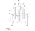
- FIG. 1 is a plan view showing a gyro sensor element 1 according to this embodiment.
- illustration of the conductive layer provided on the upper surface of the gyro sensor element 1 is basically omitted.
- the X-axis direction shown in FIG. 1 is called the first direction
- the Y-axis direction is called the second direction.
- the "upper surface” or “front surface” refers to the positive direction of the Z axis in FIG. 1, that is, the surface shown in FIG. It refers to the negative direction, ie the surface behind the surface shown in FIG.
- the gyro sensor element 1 may be integrally formed as a whole.
- the gyro sensor element 1 may be monocrystalline or polycrystalline.
- the base material of the gyro sensor element 1 may be selected as appropriate, such as crystal (SiO 2 ), LiTaO 3 , LiNbO 3 , PZT, or silicon.
- the gyro sensor element 1 may have, for example, a constant overall thickness (in the Z-axis direction).
- a gyro sensor element 1 is a sensor element used for a gyro sensor (not shown).
- the gyro sensor element 1 is made of a piezoelectric material, and includes a first base portion 2, a pair of first drive arms 3, a first detection arm 4, and a mounting portion 5, as shown in FIG. there is
- the pair of first drive arms 3 are excited in phases opposite to each other in the X-axis direction as indicated by an arrow C1 by applying an AC voltage. Being excited in phases opposite to each other means that the pair of first drive arms 3 vibrate so as to approach and separate from each other.
- the Coriolis force causes the first drive arm 3 to vibrate in the Y-axis direction as indicated by the arrow C2.
- the vibration of the first drive arm 3 is transmitted to the first detection arm 4 via the first base 2, and the first detection arm 4 performs bending vibration in the direction of the arrow C3 in the X-axis direction.
- a charge signal (for example, voltage) generated by the piezoelectric effect due to bending vibration of the first detection arm 4 is detected by a detection electrode, which will be described later, and the angular velocity is calculated from the detected voltage.
- the greater the angular velocity the greater the magnitude of the detected voltage. Further, even when detecting the same angular velocity, the larger the bending change of the first detection arm 4, the larger the voltage value obtained, so the angular velocity detection sensitivity of the gyro sensor becomes higher.
- the first base 2 supports a first drive arm 3 and a first detection arm 4 .
- the first base portion 2 extends in the first direction, and both ends thereof are supported by mounting portions 5 .
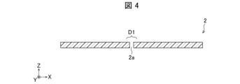
- FIG. 2 is a diagram showing the structure of the first base 2, and is a cross-sectional view taken along line IA shown in FIG.
- the first base portion 2 has a first groove portion 2a extending in the second direction in a region (region D1 shown in FIG. 1) continuous with the base end of the first detection arm 4. are doing.
- the depth of the first groove portion 2a in the Z-axis direction is not particularly limited.
- the first groove portion 2a may extend in the second direction from the base end of the first detection arm 4, which will be described later, to the distal end portion on the opposite side.
- the first base portion 2 Since the first base portion 2 has the first groove portion 2a in this way, a part of the region D1 of the first base portion 2 becomes thin, and the first base portion 2 becomes easy to bend. As the first base portion 2 bends, the first detection arm 4 tends to bend. According to this, the detection sensitivity of the gyro sensor element 1 can be improved.
- FIG. 2 is a cross-sectional view taken along line IA shown in FIG.
- the first groove portion 2a may be provided only on one surface (upper surface or lower surface) of the first base portion 2 as shown in FIG. 2, but is not limited to this. Another aspect of the first groove portion 2a will be illustrated.
- FIGS. 3 and 4 are diagrams showing the structure of the first base portion 2, respectively, and are sectional views taken along the line IA shown in FIG.
- the first base portion 2 has a first groove portion 2 a on the upper surface of the first base portion 2 and a first groove portion 2 b on the lower surface of the first base portion 2 .
- the thickness of the part of the region D1 of the first base 2 becomes thinner than the thickness of the part of the region D1 of the first base 2 shown in FIG. becomes easy to bend.
- the first detection arm 4 tends to bend.
- the first base portion 2 has a first groove portion 2a of a penetrating opening, that is, a first slit 2a.
- the groove portion of the through opening will also be referred to as a slit.
- the width of the first slit 2a may be the same from the top to the bottom of the first base 2, or may be different.
- the first slit 2a can be regarded as a form in which the bottom of the first groove 2a is removed, but only a part of the bottom of the first groove 2a is removed and a part is opened. good too.
- the first drive arm 3 is a portion that is excited by application of an AC voltage (electric field).
- the first drive arm 3 extends in the second direction from the first base 2 and has a free end.
- the first drive arm 3 can be flexurally deformed like a cantilever beam.
- the pair of first drive arms 3 are arranged in parallel with each other in the first direction, spaced apart from each other.
- FIG. 5 is a diagram showing the structure of the first driving arm 3, and is a cross-sectional view taken along line IB shown in FIG.
- the first drive arm 3 consists of two arms 3b separated by a slit 3a.
- the arm portion 3b has recesses extending in the second direction on both sides (upper surface and lower surface) in the Z-axis direction from the portion connected to the first base portion 2 to the end opposite to the first base portion 2.
- 3c second recess).
- the first drive arm 3 applies a voltage to the outer side surface of the first drive arm 3 (more specifically, the arm portion 3b) and the side surface on the side of the slit 3a.
- a first drive electrode 3d may be provided for this purpose.
- each recess 3c of the first drive arm 3 may be provided with a second drive electrode 3e to which a potential opposite to that of the first drive electrode 3d is applied.
- the other first drive arm 3 of the pair of first drive arms 3 is arranged such that the first drive electrode 3d and the second drive electrode 3e are located in the same position as one of the first drive arms 3. The opposite of the drive arm 3 may be used.
- the first drive arm 3 is provided with the second drive electrodes 3e on the outer side surface and the side surface on the side of the slit 3a, and the recesses 3c of the first drive arm 3 are provided with the first drive electrodes 3d. good too.
- the first detection arm 4 vibrates in the first direction due to the Coriolis force.
- the first detection arm 4 is provided with a first detection electrode 4g, a second detection electrode 4h, a first detection electrode 4j, and a second detection electrode 4k, which will be described later.
- a voltage generated by the piezoelectric effect resulting from the deflection in the first direction is measured by each sensing electrode.
- the first detection arm 4 may extend from the first base 2 in the second direction, as shown in FIG. In FIG. 1, as an example, the first detection arm 4 extends in the same second direction as the first drive arm 3 and is positioned between the pair of first drive arms 3, but is not limited to this.
- the first detection arm 4 may extend in the opposite direction to the direction in which the pair of first drive arms 3 extends, that is, in the negative direction of the Y-axis. Also, the first detection arm 4 may be positioned between the pair of first drive arms 3 when extending in the same second direction as the first drive arms 3 .
- the first detection arm 4 may be defined by a first groove 2a that is a bottomed groove extending from the first base 2, and the first detection arm 4 is defined by the first detection arm defined by the first groove 2a. A portion 4d and a second detection portion 4e may be provided. According to this, the first detection arm 4 has a thin portion, and the first detection arm 4 is easily bent.
- FIG. 6 is a diagram showing the configuration of the first detection arm 4, and is a cross-sectional view taken along the line IC shown in FIG.
- the first detection arm 4 has a slit 4c formed continuously with the slit 2a formed in the first base 2.
- the slit 4c may be a through opening slit.
- the slit 4c may extend from the first base portion 2 to the end opposite to the first base portion 2 .
- one slit is formed by the first slit 2a and the slit 4c.
- the first detection arm 4 may be composed of a first detection section 4d and a second detection section 4e separated by a slit 4c.
- the first detection portion 4d and the second detection portion 4e are arranged in the second direction on both sides in the Z-axis direction from the point where they are connected to the first base portion 2 to the end opposite to the first base portion 2. It may have a concave portion 4f and a concave portion 4m (first concave portion) extending inward.
- the ends of the first detection portion 4d and the second detection portion 4e may be connected to the first weight 4a, which is one weight.
- the first detection unit 4d has first detection electrodes 4g for detecting voltage generated by the piezoelectric effect on the side surface on the slit 4c side and the outer side surface, and the side surface of the recess 4f has a potential opposite to that of the first detection electrode 4g.
- a second detection electrode 4h for detecting the may be provided.
- the second detection part 4e includes first detection electrodes 4j for detecting the same voltage as the first detection electrodes 4g on the side surface on the slit 4c side and the outer side surface, and the first detection electrodes 4j on the side surfaces of the recess 4m. and a second detection electrode 4k for detecting a potential opposite to that of the second detection electrode 4k.
- the detection electrodes on the slit 4c side and the outer side of the first detection section 4d and the detection electrodes on the slit 4c side and the outer side of the second detection section 4e detect the same potential.
- the detection electrode on the side surface of the concave portion 4f of the first detection portion 4d and the detection electrode on the side surface of the concave portion 4m of the second detection portion 4e detect the same potential.
- the first base 2 extending in the second direction is provided in the region (region D1 shown in FIG. 1) continuous with the base end of the first detection arm 4 . It has a groove portion 2a (first slit). This makes it easier for the first base portion 2 to bend, so that the first detection arm 4 is easier to bend. As a result, in the gyro sensor element 1, the amplitude of vibration of the first detection arm 4 becomes larger than that of the conventional gyro sensor element, and has high detection sensitivity.
- the gyro sensor element 1 includes a first detection portion 4d and a second detection portion 4e separated by a slit 4c through which the first detection arm 4 passes. 4a.
- the first detection arm 4 has a structure in which the positions corresponding to each other change as the first detection portion 4d and the second detection portion 4e bend, so that the amplitude of vibration of the first detection arm 4 increases. .
- the detection sensitivity of the gyro sensor element 1 can be improved.
- the first detection portion 4d and the second detection portion 4e have a recess 4f and a recess 4m extending in the second direction, respectively.
- a second detection electrode 4h and a second detection electrode 4k) are provided.
- the first detection arm 4 includes a first detection electrode (that is, a first detection electrode 4g and a first detection electrode 4j) and a second detection electrode having opposite positive and negative potentials. Electrodes (ie, second detection electrode 4h and second detection electrode 4k) are provided. As a result, two potentials can be detected by the first detection arm 4, and detection sensitivity can be improved. Moreover, by covering each surface of the first detection arm 4 with electrodes, the rigidity of the first detection arm 4 can be increased.
- the first drive arm 3 extends in the second direction from the portion where the first drive arm 3 is connected to the first base portion 2 to the end opposite to the first base portion 2 (the second drive arm 3c). 2 recesses), and a first driving electrode 3d is provided on the outer side surface of the first driving arm 3 and the inner side surface of the recess 3c.
- the area for installing the driving electrodes can be made larger than that of the driving arm having no concave portion, and the electric field effect is strengthened, so that the driving arm can be vibrated more.
- the mounting portion 5 supports both ends of the first base portion 2 in the first direction. Further, the mounting portion 5 may be a portion that is fixed to, for example, a housing when the gyro sensor element 1 is mounted.
- the shape of the mounting portion 5 is not particularly limited, and it may be a frame upper member surrounding the four arms of the gyro sensor element 1 .
- the gyro sensor element 1 is basically composed of the first base portion 2, the pair of first drive arms 3, and the first detection arm 4 having the first detection portion 4d and the second detection portion 4e.
- one gyro sensor element may be provided with another unit of the above configuration.
- FIG. 7 is a plan view showing the gyro sensor element 1C.
- the gyro sensor element 1C may further include the following configurations (1) to (3) in addition to the configuration of the gyro sensor element 1.
- FIG. (1) A second base portion 12 arranged parallel to the first base portion 2 .
- (2) A pair of second drive arms 13 extending from the second base 12 in the second direction opposite to the direction in which the first drive arms 3 extend from the first base 2 .
- a second detection arm 14 extending from the second base 12 in the second direction opposite to the direction in which the first driving arm 3 extends from the first base 2 .
- a region D2 of the second base portion 12 of the gyro sensor element 1C, which is continuous with the base end of the second detection arm 14, may have a second groove portion 12a extending in the second direction.
- the second detection arm 14 may have a second groove 14c formed continuously with the second groove 12a. That is, the second groove portion 12a may extend in the second direction from the proximal end of the second detection arm 14 to the distal end on the opposite side. Further, the second groove portion 12a may be a through-opening second slit 12a, and the second groove portion 14c may be a through-opening second slit 14c.
- the second detection arm 14 of the gyro sensor element 1C may include a third detection portion 14d and a fourth detection portion 14e separated by a second groove portion 14c. That is, the third detection section 14d and the fourth detection section 14e separated by the second slit 14c may be provided. Further, the third detection section 14d may be located at the same position as the first detection section in the first direction, and the fourth detection section 14e may be located at the same position as the second detection section in the first direction.
- the third detection portion 14d and the fourth detection portion 14e are arranged in the second direction on both sides in the Z-axis direction from the point where they are connected to the second base portion 12 to the end opposite to the second base portion 12. You may have the recessed part extended to. Further, the distal ends of the third detecting portion 14d and the fourth detecting portion 14e may be connected to a second weight located at the end portion of the second detection arm 14 opposite to the proximal end thereof.
- the second drive arm 13 and the second detection arm 14 of the gyro sensor element 1C may each have an electrode.
- the pair of second drive arms 13 of the gyro sensor element 1C may be provided with first drive electrodes 3d and second drive electrodes 3e, like the pair of first drive arms 3.
- the second detection arm 14 of the gyro sensor element 1C may include first detection electrodes 4g and 4j and second detection electrodes 4h and 4k.
- the arrangement of the positive and negative electrodes of each detection electrode of the second detection arm 14 may be reverse to the arrangement of each detection electrode of the first detection arm 4 . That is, the concave portions of the third detecting portion 14d and the fourth detecting portion 14e are provided with the first detecting electrodes 4g and 4j, and the side surfaces of the third detecting portion 14d and the fourth detecting portion 14e on the side of the second slit 14c and the outer side surfaces thereof are provided with electrodes 4g and 4j. Second detection electrodes 4h and 4k may be provided.
- the gyro sensor element 1C has two structures of the gyro sensor element 1 shown in FIG. 1, one of which is inverted in the second direction. According to this, since the number of detection units included in the gyro sensor element 1 ⁇ /b>C is increased, the detection sensitivity is improved more than that of the gyro sensor element 1 ⁇ /b>C.
- FIG. 8 is a diagram showing an example of a wiring pattern on the surface of the gyro sensor element 1C, ie, the same surface as the plan view shown in FIG.
- FIG. 9 is a diagram showing an example of a wiring pattern on the back surface of the gyro sensor element 1C, and is a view of the back surface seen through from the front side.
- the wiring shown in each drawing also serves as an electrode.
- first drive arm 3A one of the pair of first drive arms 3 is called a first drive arm 3A
- first drive arm 3B one of the pair of second drive arms 13 is called a second drive arm.
- 13A and the other is called a second drive arm 13B.
- the gyro sensor element 1C may have a first wiring 420 connected to the first detection electrode.
- the first wiring 420 in FIG. 8 may be connected to the first detection electrodes 4g arranged on the slit 4c side and outer side surfaces of the first detection portion 4d.
- the first wiring 420 may be connected to the first detection electrodes 4j arranged on the slit 4c side and outer side surfaces of the second detection portion 4e.
- the first wiring 420 may be connected in the second detection arm 14 to the first detection electrodes arranged on the side surfaces of the recesses of the third detection section 14d and the fourth detection section 14e.
- the first wiring 420 may be connected to the back surface via a connecting portion 410U integrally provided from the front surface to the side surface of the first detection arm 4 .
- the connecting portion 410L is connected to the connecting portion 410U on the front surface.
- the first wiring 420 may be connected to the first detection electrodes 4g and 4j of the first detection arm 4 and the second detection arm 14, like the wiring pattern on the front surface.
- the gyro sensor element 1C may have a second wiring 410 connected to the second detection electrode.
- the second wiring 410 on the front surface of FIG. It is wiring connected to the detection electrode 4k.
- the second wiring 410 is connected to the second detection electrodes arranged on the second slit 14c side surface and the outer side surface of the third detection unit 14d, and to the second slit 14c side surface and the outer side surface of the fourth detection unit 14e. It may be connected to the arranged second detection electrode.
- the second wiring 410 is connected to the back surface via a connecting portion 410U integrally provided from the front surface to the side surface of the second detection arm 14 .
- the connecting portion 410L is connected to the connecting portion 410U on the front surface.
- the second wiring 410 may be connected to the second detection electrodes 4h and 4k of the first detection arm 4 and the second detection arm 14, like the wiring pattern on the front surface.
- the first wiring 420 and the second wiring 410 may be installed along the first base 2 and the second base 12 as a pair. According to this, the gyro sensor element 1C can efficiently detect potentials without generating excess charges, as compared with the case where the wires of the electrodes for detecting opposite potentials are arranged in different directions. Therefore, a gyro sensor element 1C with high detection sensitivity can be obtained.
- the gyro sensor element 1C corresponds to the third wiring 310 and the third wiring 320 connected to the driving electrodes (first driving electrode 3d, second driving electrode 3e).
- the third wiring 310 on the surface of FIG. 8 may be connected to the first driving electrode 3d arranged on the outer side surface of the first driving arm 3A and the side surface on the side of the slit 3a. Also, the third wiring 310 may be connected to the first drive electrode 3d arranged in the recess 3c of the first drive arm 3B. The third wiring 310 is further connected to the first driving electrode 3d arranged on the outer side surface of the second driving arm 13A and the side surface on the side of the slit 13a, and the second driving electrode 3d arranged in the concave portion of the second driving arm 13B. It may be connected to one drive electrode 3d.
- the third wiring 310 may be routed along the mounting portion 5 and connected to the rear surface via a connection portion 311U integrally provided from the front surface to the side surface of the mounting portion 5 .
- the connecting portion 311L may be connected to the connecting portion 311U on the front surface.
- the third wiring 310 may be connected to the first driving electrodes of the first driving arm 3 and the second driving arm 13, like the wiring pattern on the front surface.
- the third wiring 320 on the surface of FIG. 8 may be connected to the second drive electrode 3e to which the potential opposite to that of the first drive electrode 3d is applied.
- the third wiring 320 includes the second drive electrode 3e arranged in the recess 3c of the first drive arm 3A, the second drive electrode 3e arranged on the outer side surface of the first drive arm 3B, and the side surface on the side of the slit 3a. It may be connected to the electrode 3e.
- the third wiring 320 further includes a second drive electrode 3e arranged in the recess of the second drive arm 13A, a second drive electrode 3e arranged on the outer side surface of the second drive arm 13B, and a side surface on the side of the slit 13a. may be connected to the electrode 3e.
- the third wiring 320 may be wired along the mounting portion 5 on the front surface and connected to the rear surface via a connecting portion 321U integrally provided from the front surface to the side surface of the first driving arm 3A.
- the connecting portion 321L may be connected to the connecting portion 321U on the front surface.
- the third wiring 320 may be connected to the second driving electrodes 3e of the first driving arm 3 and the second driving arm 13, like the wiring pattern on the front surface.
- the gyro sensor element 1C may have a ground between the wiring connected to the detection electrodes and the wiring connected to the drive electrodes. That is, as shown in FIG. 9, the gyro sensor element 1C may have the ground 500 between the first wiring 420 and the second wiring 410 and the third wiring 310 and the third wiring 320 . According to this, the gyro sensor element 1C is connected to the wiring connected to the first detection electrodes 4g, 4j and the second detection electrodes 4h, 4k, and the first drive electrode 3d and the second drive electrode 3e. It is possible to reduce noise interference between the wiring and the wiring.
- the gyro sensor element 1 of the present disclosure may be formed by etching. At this time, convex portions may occur due to the influence of the crystal orientation of the quartz crystal that is the base material.
- the gyro sensor element 1 may have a convex portion on one of the surfaces of the base material of the first detection arm 4, the surface on the positive side and the surface on the negative side in the first direction.
- FIG. 10 is a diagram showing the first detection arm 4, and is a cross-sectional view taken along line 1-C shown in FIG.
- the first detection arm 4 has a convex portion 11 on the positive surface in the first direction of the first detection portion 4d and the second detection portion 4e.
- the convex portion 11 is indicated by hatching different from that of the first detection portion 4d and the second detection portion 4e for ease of explanation. be.
- FIG. 11 is a plan view showing the gyro sensor element 1D in this embodiment.
- a gyro sensor element 1D like the gyro sensor element 1C described above, has two structures of the gyro sensor element 1, one of which is inverted in the second direction. are the same.
- the gyro sensor element 1D is different from the gyro sensor element 1C in that the regions that are continuous with the base end of each detecting portion that is inverted in the second direction are connected by a bridging region.
- the first detection section 4d and the third detection section 14d may be connected by a first bridging region 21 in areas that are continuous with their base ends.
- the second bridging region 22 may connect the regions of the second detection portion 4e and the fourth detection portion 14e that are continuous with the respective proximal ends.
- the bridging region 21 and the bridging region 22 may be partitioned via a third groove portion 23 that is continuous with the first groove portion 4c and the second groove portion 14c.
- the first groove portion 4c may be the first slit 4c of the through opening
- the second groove portion 14c may be the second slit 14c of the through opening
- the third groove portion 23 may be the second slit 14c of the through opening. It may be 3 slits. That is, the first slit 4c and the second slit 14c may form an integral slit.
- the gyro sensor element 1D may include a bridging area 21 and a bridging area 22 that connect the detection units extending in the positive and negative directions of the second direction, and the two bridging areas may be partitioned or separated.
- each detecting portion can be easily bent, and the rigidity of the first detecting arm 4 and the second detecting arm 14 can be increased.
- the mounting portion 5 supports both ends of the first base portion 2 in the first direction without bending the first base portion 2 .
- both ends of the first base portion 2 ⁇ /b>C may be bent in the second direction and further bent in the first direction to be connected to the mounting portion 5 .
- FIG. 12 is a plan view showing a gyro sensor element 1B in this modified example. As shown in FIG. 12 , both ends of the first base portion 2 ⁇ /b>C are bent in the positive direction in the second direction, further bent in the first direction toward the mounting portion 5 , and connected to the mounting portion 5 . In FIG. 12, the bending angle is shown as a right angle, but the bending angle is not limited to this.
- both ends of the first base portion 2C are bent in the second direction and are further bent in the first direction to be connected to the mounting portion 5, so that the first base portion 2C is easily bent, As the first base portion 2C is curved, the first detection arm 4 is easily bent.
Landscapes
- Physics & Mathematics (AREA)
- Engineering & Computer Science (AREA)
- General Physics & Mathematics (AREA)
- Radar, Positioning & Navigation (AREA)
- Remote Sensing (AREA)
- Gyroscopes (AREA)
Abstract
Un capteur gyroscopique selon un aspect de la présente divulgation comprend une première partie de base s'étendant dans une première direction, une paire de premiers bras d'entraînement s'étendant à partir de la première partie de base dans une seconde direction croisant la première direction, et un premier bras de détection s'étendant à partir de la première partie de base. Une région de la première partie de base continue avec l'extrémité de base du premier bras de détection a une première rainure s'étendant dans la seconde direction.
Applications Claiming Priority (2)
| Application Number | Priority Date | Filing Date | Title |
|---|---|---|---|
| JP2021186532 | 2021-11-16 | ||
| JP2021-186532 | 2021-11-16 |
Publications (1)
| Publication Number | Publication Date |
|---|---|
| WO2023090349A1 true WO2023090349A1 (fr) | 2023-05-25 |
Family
ID=86397082
Family Applications (1)
| Application Number | Title | Priority Date | Filing Date |
|---|---|---|---|
| PCT/JP2022/042514 WO2023090349A1 (fr) | 2021-11-16 | 2022-11-16 | Élément de capteur gyroscopique |
Country Status (1)
| Country | Link |
|---|---|
| WO (1) | WO2023090349A1 (fr) |
Citations (4)
| Publication number | Priority date | Publication date | Assignee | Title |
|---|---|---|---|---|
| JPH11281372A (ja) * | 1997-11-04 | 1999-10-15 | Ngk Insulators Ltd | 振動子、振動型ジャイロスコープ、直線加速度計および回転角速度の測定方法 |
| JP2004007428A (ja) * | 2002-03-25 | 2004-01-08 | Seiko Epson Corp | 音叉型圧電振動片及びその製造方法、圧電デバイス |
| JP2010117374A (ja) * | 2010-02-24 | 2010-05-27 | Epson Toyocom Corp | ジャイロモジュール |
| JP2013007656A (ja) * | 2011-06-24 | 2013-01-10 | Seiko Epson Corp | 屈曲振動片及び電子機器 |
-
2022
- 2022-11-16 WO PCT/JP2022/042514 patent/WO2023090349A1/fr unknown
Patent Citations (4)
| Publication number | Priority date | Publication date | Assignee | Title |
|---|---|---|---|---|
| JPH11281372A (ja) * | 1997-11-04 | 1999-10-15 | Ngk Insulators Ltd | 振動子、振動型ジャイロスコープ、直線加速度計および回転角速度の測定方法 |
| JP2004007428A (ja) * | 2002-03-25 | 2004-01-08 | Seiko Epson Corp | 音叉型圧電振動片及びその製造方法、圧電デバイス |
| JP2010117374A (ja) * | 2010-02-24 | 2010-05-27 | Epson Toyocom Corp | ジャイロモジュール |
| JP2013007656A (ja) * | 2011-06-24 | 2013-01-10 | Seiko Epson Corp | 屈曲振動片及び電子機器 |
Similar Documents
| Publication | Publication Date | Title |
|---|---|---|
| JP6260706B2 (ja) | 改良された直交位相補正を有するジャイロスコープ構造体およびジャイロスコープ | |
| JP3882973B2 (ja) | 角速度センサ | |
| JP4654668B2 (ja) | ジャイロセンサおよびそれを用いたセンサ装置 | |
| EP1860402A1 (fr) | Capteur de débit angulaire | |
| US7546768B2 (en) | Mounting structure of angular rate sensor | |
| JP2002131331A (ja) | 半導体力学量センサ | |
| JP6620243B2 (ja) | 角速度センサ、センサ素子および多軸角速度センサ | |
| JP2005241500A (ja) | 角速度センサ | |
| JP6581728B2 (ja) | 角速度センサ、センサ素子および多軸角速度センサ | |
| WO2010041422A1 (fr) | Élément de capteur de vitesse angulaire, capteur de vitesse angulaire et unité de capteur de vitesse angulaire utilisant tous deux l'élément de capteur de vitesse angulaire, et procédé de détection de signal pour unité de capteur de vitesse angulaire | |
| JP6267979B2 (ja) | 角速度センサ及びセンサ素子 | |
| WO2023090349A1 (fr) | Élément de capteur gyroscopique | |
| JP2012149961A (ja) | 振動ジャイロ | |
| JP5407259B2 (ja) | 角速度センサ素子 | |
| JP6074629B2 (ja) | 角速度センサ素子及び角速度センサ | |
| JP2012112819A (ja) | 振動ジャイロ | |
| JP2011209270A (ja) | 角速度センサ素子 | |
| JP5786141B2 (ja) | 角速度センサ素子 | |
| JP5849243B2 (ja) | 角速度センサ素子 | |
| JP5849190B2 (ja) | 角速度センサ素子 | |
| JP2004301575A (ja) | 角速度センサ | |
| JP2008261771A (ja) | 慣性力センサ | |
| JP2017009404A (ja) | 慣性力センサ | |
| JP2016070738A (ja) | センサ |
Legal Events
| Date | Code | Title | Description |
|---|---|---|---|
| 121 | Ep: the epo has been informed by wipo that ep was designated in this application |
Ref document number: 22895630 Country of ref document: EP Kind code of ref document: A1 |