WO2023089897A1 - 伸縮デバイス - Google Patents
伸縮デバイス Download PDFInfo
- Publication number
- WO2023089897A1 WO2023089897A1 PCT/JP2022/032254 JP2022032254W WO2023089897A1 WO 2023089897 A1 WO2023089897 A1 WO 2023089897A1 JP 2022032254 W JP2022032254 W JP 2022032254W WO 2023089897 A1 WO2023089897 A1 WO 2023089897A1
- Authority
- WO
- WIPO (PCT)
- Prior art keywords
- hole
- base material
- wiring
- shortest distance
- main surface
- Prior art date
- Legal status (The legal status is an assumption and is not a legal conclusion. Google has not performed a legal analysis and makes no representation as to the accuracy of the status listed.)
- Ceased
Links
Images





Classifications
-
- H—ELECTRICITY
- H05—ELECTRIC TECHNIQUES NOT OTHERWISE PROVIDED FOR
- H05K—PRINTED CIRCUITS; CASINGS OR CONSTRUCTIONAL DETAILS OF ELECTRIC APPARATUS; MANUFACTURE OF ASSEMBLAGES OF ELECTRICAL COMPONENTS
- H05K1/00—Printed circuits
- H05K1/02—Details
- H05K1/0277—Bendability or stretchability details
- H05K1/0283—Stretchable printed circuits
-
- H—ELECTRICITY
- H05—ELECTRIC TECHNIQUES NOT OTHERWISE PROVIDED FOR
- H05K—PRINTED CIRCUITS; CASINGS OR CONSTRUCTIONAL DETAILS OF ELECTRIC APPARATUS; MANUFACTURE OF ASSEMBLAGES OF ELECTRICAL COMPONENTS
- H05K1/00—Printed circuits
- H05K1/02—Details
- H05K1/14—Structural association of two or more printed circuits
- H05K1/144—Stacked arrangements of planar printed circuit boards
-
- H—ELECTRICITY
- H05—ELECTRIC TECHNIQUES NOT OTHERWISE PROVIDED FOR
- H05K—PRINTED CIRCUITS; CASINGS OR CONSTRUCTIONAL DETAILS OF ELECTRIC APPARATUS; MANUFACTURE OF ASSEMBLAGES OF ELECTRICAL COMPONENTS
- H05K1/00—Printed circuits
- H05K1/02—Details
- H05K1/14—Structural association of two or more printed circuits
- H05K1/145—Arrangements wherein electric components are disposed between and simultaneously connected to two planar printed circuit boards, e.g. Cordwood modules
-
- H—ELECTRICITY
- H05—ELECTRIC TECHNIQUES NOT OTHERWISE PROVIDED FOR
- H05K—PRINTED CIRCUITS; CASINGS OR CONSTRUCTIONAL DETAILS OF ELECTRIC APPARATUS; MANUFACTURE OF ASSEMBLAGES OF ELECTRICAL COMPONENTS
- H05K1/00—Printed circuits
- H05K1/18—Printed circuits structurally associated with non-printed electric components
- H05K1/189—Printed circuits structurally associated with non-printed electric components characterised by the use of flexible or folded printed circuits
-
- H—ELECTRICITY
- H05—ELECTRIC TECHNIQUES NOT OTHERWISE PROVIDED FOR
- H05K—PRINTED CIRCUITS; CASINGS OR CONSTRUCTIONAL DETAILS OF ELECTRIC APPARATUS; MANUFACTURE OF ASSEMBLAGES OF ELECTRICAL COMPONENTS
- H05K3/00—Apparatus or processes for manufacturing printed circuits
- H05K3/36—Assembling printed circuits with other printed circuits
- H05K3/361—Assembling flexible printed circuits with other printed circuits
-
- H—ELECTRICITY
- H05—ELECTRIC TECHNIQUES NOT OTHERWISE PROVIDED FOR
- H05K—PRINTED CIRCUITS; CASINGS OR CONSTRUCTIONAL DETAILS OF ELECTRIC APPARATUS; MANUFACTURE OF ASSEMBLAGES OF ELECTRICAL COMPONENTS
- H05K1/00—Printed circuits
- H05K1/02—Details
- H05K1/03—Use of materials for the substrate
- H05K1/0393—Flexible materials
-
- H—ELECTRICITY
- H05—ELECTRIC TECHNIQUES NOT OTHERWISE PROVIDED FOR
- H05K—PRINTED CIRCUITS; CASINGS OR CONSTRUCTIONAL DETAILS OF ELECTRIC APPARATUS; MANUFACTURE OF ASSEMBLAGES OF ELECTRICAL COMPONENTS
- H05K1/00—Printed circuits
- H05K1/02—Details
- H05K1/11—Printed elements for providing electric connections to or between printed circuits
- H05K1/118—Printed elements for providing electric connections to or between printed circuits specially for flexible printed circuits, e.g. using folded portions
-
- H—ELECTRICITY
- H05—ELECTRIC TECHNIQUES NOT OTHERWISE PROVIDED FOR
- H05K—PRINTED CIRCUITS; CASINGS OR CONSTRUCTIONAL DETAILS OF ELECTRIC APPARATUS; MANUFACTURE OF ASSEMBLAGES OF ELECTRICAL COMPONENTS
- H05K2201/00—Indexing scheme relating to printed circuits covered by H05K1/00
- H05K2201/03—Conductive materials
- H05K2201/0302—Properties and characteristics in general
- H05K2201/0314—Elastomeric connector or conductor, e.g. rubber with metallic filler
-
- H—ELECTRICITY
- H05—ELECTRIC TECHNIQUES NOT OTHERWISE PROVIDED FOR
- H05K—PRINTED CIRCUITS; CASINGS OR CONSTRUCTIONAL DETAILS OF ELECTRIC APPARATUS; MANUFACTURE OF ASSEMBLAGES OF ELECTRICAL COMPONENTS
- H05K2201/00—Indexing scheme relating to printed circuits covered by H05K1/00
- H05K2201/05—Flexible printed circuits [FPCs]
- H05K2201/058—Direct connection between two or more FPCs or between flexible parts of rigid PCBs
-
- H—ELECTRICITY
- H05—ELECTRIC TECHNIQUES NOT OTHERWISE PROVIDED FOR
- H05K—PRINTED CIRCUITS; CASINGS OR CONSTRUCTIONAL DETAILS OF ELECTRIC APPARATUS; MANUFACTURE OF ASSEMBLAGES OF ELECTRICAL COMPONENTS
- H05K2201/00—Indexing scheme relating to printed circuits covered by H05K1/00
- H05K2201/09—Shape and layout
- H05K2201/09009—Substrate related
- H05K2201/09063—Holes or slots in insulating substrate not used for electrical connections
-
- H—ELECTRICITY
- H05—ELECTRIC TECHNIQUES NOT OTHERWISE PROVIDED FOR
- H05K—PRINTED CIRCUITS; CASINGS OR CONSTRUCTIONAL DETAILS OF ELECTRIC APPARATUS; MANUFACTURE OF ASSEMBLAGES OF ELECTRICAL COMPONENTS
- H05K2201/00—Indexing scheme relating to printed circuits covered by H05K1/00
- H05K2201/09—Shape and layout
- H05K2201/09209—Shape and layout details of conductors
- H05K2201/09218—Conductive traces
- H05K2201/09236—Parallel layout
-
- H—ELECTRICITY
- H05—ELECTRIC TECHNIQUES NOT OTHERWISE PROVIDED FOR
- H05K—PRINTED CIRCUITS; CASINGS OR CONSTRUCTIONAL DETAILS OF ELECTRIC APPARATUS; MANUFACTURE OF ASSEMBLAGES OF ELECTRICAL COMPONENTS
- H05K2201/00—Indexing scheme relating to printed circuits covered by H05K1/00
- H05K2201/09—Shape and layout
- H05K2201/09818—Shape or layout details not covered by a single group of H05K2201/09009 - H05K2201/09809
- H05K2201/09854—Hole or via having special cross-section, e.g. elliptical
Definitions
- the present disclosure relates to elastic devices.
- Patent Document 1 Japanese Unexamined Patent Application Publication No. 2013-145842
- This stretchable device includes a stretchable circuit body having a stretchable insulating base material and a stretchable wiring portion, a non-stretchable component mounting substrate laminated on a predetermined region of the stretchable circuit body, and a component mounting structure. and an electrical connecting portion for electrically connecting the wiring portion of the substrate and the wiring portion of the stretchable circuit body.
- the component mounting board is provided with an expansion/contraction prevention guard that prevents the expansion/contraction of the area including the electrical connection portion of the expandable circuit body.
- the wiring portion of the stretchable circuit body near the stretch prevention guard may break.
- the stretchable portion and the non-stretchable portion of the wiring portion are opposite to each other.
- a tensile force that pulls is generated and becomes a starting point of disconnection of the wiring part. In this way, there is a risk that the wiring portion will break as the stretchable device expands.
- the present disclosure is to provide a stretchable device that can suppress disconnection of wiring due to stretching of the stretchable device.
- a stretchable device includes: a stretchable first substrate having first and second major surfaces facing each other and extending in a first direction; a stretchable first wiring provided on the first main surface and extending along the first main surface; a second substrate having third and fourth major surfaces facing each other; a second wiring provided on the third main surface and extending along the third main surface; A connection member that connects the first base material and the second base material,
- the first base includes a connection region that overlaps with the second base and a non-connection region that does not overlap with the second base when viewed from a direction orthogonal to the first main surface, the connection member overlaps the connection region when viewed from a direction orthogonal to the first main surface;
- the first base material has a first hole provided in at least one of the first principal surface and the second principal surface in the non-connection region.
- on the main surface refers not to an absolute direction such as the vertical direction defined by the direction of gravity, but to an outward direction between the outer side and the inner side of the substrate bounded by the main surface. . Therefore, “on the major surface” is a relative direction determined by the orientation of the major surface.
- “above” an element includes not only the position directly above (on) in contact with the element, but also the position above the element, that is, the position above the element via another object. Also includes a spaced above position.
- extending in the first direction means extending along a single path rather than branching and extending into a plurality of paths. or extending spirally.
- the first direction is not limited to the longitudinal direction of the first substrate, but refers to the stretch direction of the first substrate.
- the hole may have a bottom that does not penetrate the first base material (the first main surface and the second main surface), or may have a bottom that does not penetrate the first base material (the first main surface and the second main surface). surface).
- the hole is not limited to a circular, elliptical, or polygonal shape, and includes a slit shape when viewed from the direction perpendicular to the first main surface.
- the hole portion is not limited to a closed hole whose inner surface is continuous in the circumferential direction when viewed from the direction perpendicular to the first main surface. contains an open hole that opens into the
- the first base material has the first hole in the non-connection region
- the vicinity of the first hole part of the first base material is elongated.
- the elongation of the first substrate in the vicinity of the connection region can be reduced.
- disconnection of the first wiring in the vicinity of the non-connection region can be suppressed, and disconnection of the first wiring due to elongation of the first base material of the elastic device can be suppressed.
- a stretchable first substrate having first and second major surfaces facing each other and extending in a first direction; a stretchable first wiring provided on the first main surface and extending along the first main surface; a second substrate having third and fourth major surfaces facing each other; a second wiring provided on the third main surface and extending along the third main surface;
- the first base includes a connection region that overlaps with the second base and a non-connection region that does not overlap with the second base when viewed from a direction orthogonal to the first main surface, The first base material and the second base material are connected in the connection region, The first base material has a first hole provided in at least one of the first principal surface and the second principal surface in the non-connection region.
- the first base material since the first base material has the first hole in the non-connection region, when the first base material is stretched in the first direction, the vicinity of the first hole part of the first base material is Elongation becomes easier, and the elongation of the vicinity of the connection region of the first base material can be reduced. As a result, disconnection of the first wiring in the vicinity of the non-connection region can be suppressed, and disconnection of the first wiring due to elongation of the first base material of the elastic device can be suppressed.
- the first hole penetrates the first substrate.
- the vicinity of the first hole portion of the first base material is more easily stretched, and the extension of the vicinity of the connection region of the first base material is further reduced, resulting in the extension of the first base material. Disconnection of the first wiring can be further suppressed.
- the shortest distance in the first direction between the first hole and the connection area is larger than the maximum diameter of the first hole in the first direction.
- the first hole can be separated from the connection area, and the extension of the first base material in the vicinity of the connection area can be further reduced, thereby reducing the length of the first wiring due to the extension of the first base material. Disconnection can be suppressed more.
- a portion of the first substrate exists between the first wiring and the first hole in a second direction perpendicular to the first direction.
- the first hole can be separated from the first wiring to prevent the first wiring from being exposed from the first hole. This can reduce the risk of the first hole coming into contact with the first wiring due to displacement of the first hole, and can suppress damage to the first wiring from the outside through the first hole.
- the stretching device further comprising a second hole arranged in the first direction with respect to the first hole; the first hole is closer to the connection region than the second hole, In the first direction, the shortest distance between the connection area and the first hole is greater than the shortest distance between the first hole and the second hole.
- the elongation of the first substrate near the first hole and the second hole is increased to further reduce the elongation of the first substrate near the connecting region, thereby: Breakage of the first wiring due to elongation of the first base material can be further suppressed.
- first hole can be separated from the connection area, and the extension of the first substrate in the vicinity of the connection area can be further reduced.
- the first hole and the second hole can be brought closer together, and the extension of the first substrate near the first hole and the second hole can be increased to increase the connection area of the first substrate. Neighborhood elongation can be further reduced.
- the stretching device further comprising a third hole arranged in the first direction with respect to the first hole and the second hole; the second hole is closer to the connection region than the third hole, In the first direction, the shortest distance between the first hole and the second hole is greater than the shortest distance between the second hole and the third hole.
- the second hole can be separated from the connection area, and the extension of the first substrate in the vicinity of the connection area can be further reduced.
- the second hole and the third hole can be brought closer, and the elongation of the vicinity of the second hole and the third hole of the first base material can be increased to increase the connection area of the first base material. Neighborhood elongation can be further reduced.
- a said 1st wiring is arrange
- the elongation of the first substrate near the first hole and the fourth hole is increased to further reduce the elongation of the first substrate near the connecting region, thereby: Breakage of the first wiring due to elongation of the first base material can be further suppressed.
- the stretching device further comprising a fifth hole arranged in the first direction with respect to the fourth hole; In the first direction, the fourth hole is closer to the connection region than the fifth hole.
- the elongation of the first substrate near the fourth hole and the fifth hole is increased to further reduce the elongation of the first substrate near the connecting region, thereby: Breakage of the first wiring due to elongation of the first base material can be further suppressed.
- the first hole is closer to the connection region than the second hole, In the first direction, the shortest distance between the first hole and the connection area is different from the shortest distance between the fourth hole and the connection area, In the first direction, the shortest distance between the second hole and the connection area is different from the shortest distance between the fifth hole and the connection area.
- the second hole arranged in the first direction with respect to the first hole and the fifth hole arranged in the first direction with respect to the fourth hole are They are arranged in a staggered pattern.
- the second hole and the fifth hole are arranged in a staggered manner
- the center of the second hole and the center of the fifth hole overlap in the second direction perpendicular to the first direction. It is preferable that the entire second hole and the entire fifth hole do not overlap.
- the stretching device further comprising a second hole arranged in the first direction with respect to the first hole; In the first direction, the first hole is closer to the connection region than the second hole, In the first direction, the shortest distance between the first hole and the connection area is equal to the shortest distance between the fourth hole and the connection area, In the first direction, the shortest distance between the second hole and the connection area is different from the shortest distance between the fifth hole and the connection area.
- the second hole arranged in the first direction with respect to the first hole and the fifth hole arranged in the first direction with respect to the fourth hole are They are arranged in a staggered pattern.
- the second hole and the fifth hole are arranged in a staggered manner
- the center of the second hole and the center of the fifth hole overlap in the second direction perpendicular to the first direction. It is preferable that the entire second hole and the entire fifth hole do not overlap.
- one embodiment of the stretchable device further comprises a protective film covering at least part of the first main surface of the first substrate and at least part of the first wiring.
- the protective film covers at least part of the first wiring, so insulation from disturbance factors can be ensured, and discomfort to the user can be suppressed when used on a living body. Moreover, since the protective film covers at least a part of the first main surface of the first base material, it is possible to suppress discomfort to the user when used on a living body. It should be noted that this embodiment can also be used for subjects other than living organisms. Also, a biocompatible material may be used for the protective film, in which case discomfort to the user can be suppressed. Note that the protective film does not have to be biocompatible.
- the protective film has a through-hole that overlaps with the hole when viewed from a direction orthogonal to the first main surface.
- the protective film even if the protective film is provided, it is possible to increase the elongation of the first substrate in the vicinity of the hole and reduce the elongation of the first substrate in the vicinity of the connection region.
- the protective film has an overlapping portion that overlaps with the hole when viewed from a direction perpendicular to the first main surface, The overlapping portion is positioned outside the hole.
- the internal space of the hole can be secured, the elongation of the first base material near the hole part can be increased, and the elongation of the first base material near the connection region can be reduced.
- the stretchable device According to the stretchable device according to one aspect of the present disclosure, it is possible to suppress disconnection of wiring due to stretching of the stretchable device.
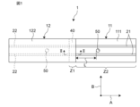
- FIG. 1 is a plan view showing a first embodiment of an elastic device
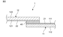
- FIG. FIG. 2 is a cross-sectional view taken along the line II-II of FIG. 1
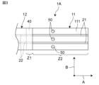
- Fig. 10 is a plan view showing a second embodiment of an elastic device
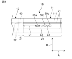
- Fig. 11 is a plan view showing a third embodiment of an elastic device
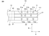
- FIG. 11 is a plan view showing a fourth embodiment of an elastic device
- FIG. 11 is a plan view showing a fifth embodiment of an elastic device
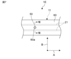
- FIG. 11 is a plan view showing a sixth embodiment of an elastic device
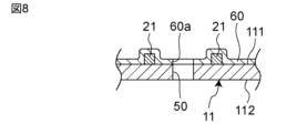
- 8 is a cross-sectional view taken along line VIII-VIII of FIG. 7;
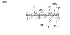
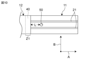
- FIG. 4 is a cross-sectional view showing another form of a protective film; It is a top view explaining the 1st example of an elastic device.
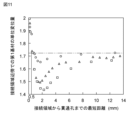
- 5 is a graph showing the relationship between the shortest distance from the connection region to the hole and the unit displacement amount of the first base material in the vicinity of the connection region.
- FIG. 10 is a plan view illustrating a second embodiment of an elastic device; 4 is a graph showing the relationship between the number of holes and the amount of unit displacement of the first base material in the vicinity of the connection region.
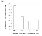
- FIG. 11 is a plan view illustrating a third embodiment of the elastic device; 5 is a graph showing the relationship between the shortest distance from the connection region to the hole and the unit displacement amount of the first base material in the vicinity of the connection region.
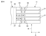
- FIG. 11 is a plan view illustrating a fourth embodiment of the elastic device; 7 is a graph showing the relationship between the shortest distance from the connection region to the second row of holes and the unit displacement amount of the first substrate in the vicinity of the connection region.
- FIG. 11 is a plan view illustrating a fifth embodiment of the elastic device; 4 is a graph showing the relationship between the number of rows of holes and the amount of unit displacement of the first base material in the vicinity of the connection region.
- FIG. 10 is a graph illustrating the stretchable device of Example 6 and showing the amount of stretching of the stretchable device when the wiring is broken in the vicinity of the connection area.
- FIG. 1 is a plan view showing a first embodiment of an elastic device
- FIG. 2 is a cross-sectional view taken along the line II--II in FIG.
- the stretchable device is attached to a living body and used to measure biological signals.
- the stretchable device 1 includes a stretchable first base material 11, a stretchable first wiring 21 provided on the first base material 11, a second base material 12, and a second base material 12.
- a second wiring 22 provided on two base materials 12 , and a connection member 40 connecting the first base material 11 and the second base material 12 and connecting the first wiring 21 and the second wiring 22 .
- the first base material 11 has a first main surface 111 and a second main surface 112 facing each other.
- the first base material 11 extends in the first direction A.
- the first base material 11 is formed in a rectangular shape having long sides along the first direction A.
- the width of the first base material 11 is constant along the first direction A. As shown in FIG. The width refers to the length in the second direction B orthogonal to the first direction A.
- the first base material 11 is made of an elastic resin material such as styrene resin, olefin resin, epoxy resin, urethane resin, acrylic resin, or silicone resin, preferably urethane resin.
- Urethane resins include thermoplastic polyurethane (TPU).
- Styrene resins include styrene-butadiene-styrene copolymer resins (SBS).
- the expansion ratio of the first base material 11 is preferably 50% or more. By setting the stretch rate to the above range, the stretchable device has good followability to the living body.
- the Young's modulus of the first base material 11 is preferably 100 MPa or less, more preferably 30 MPa or less. By setting the Young's modulus as described above, it is possible to suppress the user's discomfort.
- the thickness of the first base material 11 is, for example, 0.1 ⁇ m or more and 100 ⁇ m or less.
- the width of the first base material 11 is, for example, 10 mm or more and 100 mm or less.
- the first wiring 21 is provided on the first main surface 111 and extends along the first main surface 111 .
- the first wiring 21 extends along the first direction A.
- a plurality of first wirings 21 are present, and the plurality of first wirings 21 are arranged side by side in the second direction B. As shown in FIG. In the first embodiment, there are two first wirings 21 .
- the first wiring 21 is made of a stretchable conductive material.
- a stretchable conductive material for example, a mixture of metal powder such as silver, copper, nickel, etc. and elastomeric resin such as silicone is used.
- the average particle size D50 of the metal powder is preferably 0.01 ⁇ m or more and 10 ⁇ m or less.
- the shape of the metal powder may be a spherical shape, a flat shape, an irregular shape having projections, or the like.
- the thickness of the first wiring 21 is preferably 100 ⁇ m or less, more preferably 50 ⁇ m or less, and preferably 1 ⁇ m or more, more preferably 10 ⁇ m or more.
- the width of the first wiring 21 is preferably 0.1 mm or more and 4 mm or less.
- the first wiring 21 is formed by screen printing, inkjet printing, dispensing, or etching of metal foil so as to be in direct contact with the first main surface 111 .
- the first wiring 21 may be arranged on the first main surface 111 via an insulating film (not shown) having an insulating property. Also, the first wiring 21 may be covered with an insulating film.
- the second base material 12 has a third main surface 121 and a fourth main surface 122 facing each other.
- the second base material 12 extends in the first direction A.
- the second base material 12 is formed in a rectangular shape having long sides along the first direction A.
- the width of the second base material 12 is constant along the first direction A. As shown in FIG. The width refers to the length in the second direction B.
- the second base material 12 is made of a resin material such as styrene resin, olefin resin, epoxy resin, urethane resin, acrylic resin, or silicone resin.
- the second substrate 12 may be, for example, a flexible printed circuit (FPC) or printed circuit board (PCB).
- the second substrate 12 may be stretchable. When the second base material 12 is stretchable, the stretch load applied to the second base material 12 can be reduced.
- the expansion ratio of the second base material 12 is preferably 50% or more. By setting the stretch rate to the above range, the stretchable device has good followability to the living body.
- the Young's modulus of the second base material 12 is preferably 100 MPa or less, more preferably 30 MPa or less. By setting the Young's modulus as described above, it is possible to suppress the user's discomfort.
- the thickness of the second base material 12 is, for example, 0.1 ⁇ m or more and 100 ⁇ m or less.
- the width of the second base material 12 is, for example, 10 mm or more and 100 mm or less.
- the second wiring 22 is provided on the third main surface 121 and extends along the third main surface 121 .
- the second wiring 22 extends along the first direction A.
- a plurality of second wirings 22 are present, and the plurality of second wirings 22 are arranged side by side in the second direction B.
- the second wiring 22 is made of a conductive material.
- a conductive material for example, a metal foil of silver, copper, nickel, or the like may be used.
- a mixture consisting of The thickness of the metal foil is preferably 0.01 ⁇ m or more and 10 ⁇ m or less, and the average particle size D50 of the metal powder is preferably 0.01 ⁇ m or more and 10 ⁇ m or less.
- the shape of the metal powder may be a spherical shape, a flat shape, an irregular shape having projections, or the like.
- the second wiring 22 may be stretchable.
- the thickness of the second wiring 22 is preferably 100 ⁇ m or less, more preferably 50 ⁇ m or less, and preferably 1 ⁇ m or more, more preferably 10 ⁇ m or more.
- the width of the second wiring 22 is preferably 0.1 mm or more and 4 mm or less.
- the second wiring 22 is formed by screen printing, inkjet printing, dispensing, or etching of metal foil so as to be in direct contact with the third main surface 121 .
- the second wiring 22 may be arranged on the third main surface 121 via an insulating film (not shown) having insulating properties, and the second wiring 22 may be covered with an insulating film. .
- the first base material 11 and the second base material 12 are arranged so that their ends in the first direction A overlap each other. Specifically, the first base material 11 and the second base material 12 are arranged such that the first main surface 111 and the third main surface 121 face each other. The first wiring 21 and the second wiring 22 are arranged to face each other.
- connection member 40 is arranged between the first base material 11 and the second base material 12 at the portion where the first base material 11 and the second base material 12 overlap each other. to connect.
- connection member 40 is arranged between the first wiring 21 and the second wiring 22 in the overlapping portion of the first base material 11 and the second base material 12, and connects the first wiring 21 and the second wiring 22. Connecting.
- the connection member 40 has adhesiveness and electrical conductivity. Since the connection member 40 has conductivity, the first wiring 21 and the second wiring 22 are electrically connected via the connection member 40 .
- the method of connecting the first base material 11 and the second base material 12 is not limited to the method described above.
- the base material 11 and the second base material 12 may be arranged, and the first base material 11 and the second base material 12 may be connected by the connection member 40 .
- connection member 40 is, for example, an anisotropic conductive film (ACF), has conductivity in a direction orthogonal to the first main surface 111, and is insulated in a plane direction parallel to the first main surface 111. have sex.
- the connection member 40 includes a thermosetting epoxy resin and conductive particles dispersed in the epoxy resin. Therefore, the first wiring 21 conducts only to the immediately above second wiring 22 and does not conduct to the first wiring 21 adjacent in the direction of the first main surface 111 and the second wiring 22 not directly above.
- connection member 40 is, for example, preferably 1 ⁇ m or more and 100 ⁇ m or less, more preferably 5 ⁇ m or more and 50 ⁇ m or less.
- the width of the connection member 40 should be able to cover the first wiring 21 and the second wiring 22 to be connected. is preferred.
- the first base material 11 includes a connection area Z1 that overlaps with the second base material 12 and a non-connection area Z2 that does not overlap with the second base material 12 when viewed in a direction perpendicular to the first main surface 111 .
- the connection member 40 overlaps the connection region Z1 when viewed from the direction perpendicular to the first main surface 111 .
- the first base material 11 and the second base material 12 are connected in the connection area Z1.
- the first base material 11 has a hole 50 provided in the first main surface 111 in the non-connection region Z2.
- the hole 50 corresponds to an example of the "first hole” described in the claims. Hole 50 penetrates first main surface 111 and second main surface 112 .
- the hole portion 50 is formed in a circular shape when viewed from the direction perpendicular to the first main surface 111 .
- the diameter of the hole 50 is, for example, 0.4 mm.
- the hole 50 is located in the center of the width direction of the first base material 11 and located between the two first wirings 21 .
- the first base material 11 has the hole 50 in the non-connection region Z2.
- the vicinity becomes easy to stretch, and the extension of the vicinity of the connection region Z1 of the 1st base material 11 can be reduced.
- the vicinity of the connection region Z1 of the first base material 11 refers to a range within 300 ⁇ m from the connection region Z1. That is, the extension of the first base material 11 in the first direction A can be absorbed in the vicinity of the hole 50 of the first base material 11 .
- the Young's modulus of the non-connected region Z2 is smaller than the Young's modulus of the connected region Z1.
- the hole 50 may be provided in the first main surface 111 and have a bottom that does not penetrate the second main surface 112. In this case, the above effects are also obtained.
- the hole portion 50 may be provided on the second main surface 112 and have a bottom that does not penetrate through the first main surface 111. Even in this case, the above effects are obtained. By having the hole 50 penetrate through the first base material 11 as in this embodiment, a more remarkable effect can be obtained.
- the second base material 12 and the second wiring 22 may be stretchable.
- the second base material 12 also includes a connection region that overlaps the connection member 40 and a non-connection region that does not overlap the connection member 40.
- at least one of the third main surface 121 and the fourth main surface 122 may have a hole 50 in the non-connection region.
- the hole 50 penetrates through the second base material 12 to obtain a more remarkable effect.
- the shape of the hole 50 may be elliptical, polygonal, or slit-shaped.
- the hole portion 50 preferably has a shape that is long in the first direction A, so that the extension of the vicinity of the hole portion 50 can be increased.
- connection member 40 may be present between the first base material 11 and the second base material 12 instead of being present between the first wiring 21 and the second wiring 22 . Also, the connection member 40 may not be provided, and the first base material 11 and the second base material 12 may be directly connected by welding or the like.
- connection region Z1 of the first base material 11 is a region that overlaps with the second base material 12 and is connected to the second base material 12 when viewed from the direction orthogonal to the first main surface 111.
- the non-connection region Z2 of the material 11 is a region that does not overlap the second base material 12 and is not connected to the second base material 12 when viewed from the direction orthogonal to the first main surface 111 .
- the shortest distance L in the first direction A between the hole 50 and the connection region Z1 is larger than the maximum diameter of the hole 50 in the first direction A.
- the shortest distance L is, for example, 0.5 mm or more and 10 mm or less, preferably 0.8 mm or more and 7 mm or less, more preferably 1 mm or more and 6.5 mm or less, still more preferably 1.3 mm or more and 6 mm or less.
- the hole portion 50 can be separated from the connection region Z1, the extension of the first substrate 11 near the connection region Z1 is further reduced, and the extension of the first substrate 11 accompanying the extension of the first substrate 11 is reduced. Disconnection of the wiring 21 can be further suppressed.
- the hole part in the 2nd base material 12 it is preferable that it is the structure similar to the said 1st base material 11.
- a portion of the first base material 11 exists between the first wiring 21 and the hole 50 in the second direction B.
- the shortest distance between the two first wirings 21 is, for example, 0.5 mm, preferably 100 ⁇ m larger than the diameter of the hole 50, more preferably 200 ⁇ m larger than the diameter of the hole 50, and even more preferably 200 ⁇ m larger than the diameter of the hole 50. 300 ⁇ m larger than the diameter of the portion 50 .
- FIG. 3 is a plan view showing a second embodiment of an elastic device;
- FIG. 2nd Embodiment differs in the structure of a hole part from 1st Embodiment. This different configuration is described below. The rest of the configuration is the same as that of the first embodiment, and the same reference numerals as those of the first embodiment are given, and the description thereof is omitted.
- the first base material 11 has a plurality of holes 50, and the holes 50 are located on both sides of the first wiring 21 in the second direction B. located in each.
- the second embodiment since there are two first wirings 21, there are three holes 50.
- FIG. The plurality of holes 50 are arranged in a straight line in the second direction B.
- the hole 50 positioned on one side of the first wiring 21 in the second direction B corresponds to an example of the "first hole” described in the claims, and the hole 50 on the other side of the first wiring 21 in the second direction B
- the hole 50 located on the side corresponds to an example of the "fourth hole” described in the claims.
- the extension of the first substrate 11 in the vicinity of the plurality of holes 50 is further increased, and the extension of the first substrate 11 in the vicinity of the connection region Z1 is further reduced. Disconnection of the first wiring 21 due to the extension of the base material 11 can be further suppressed.
- the structure be the same as that of the first base material 11 described above.
- FIG. 4 is a plan view showing a third embodiment of an elastic device; 3rd Embodiment differs in the structure of a hole part from 1st Embodiment. This different configuration is described below. The rest of the configuration is the same as that of the first embodiment, and the same reference numerals as those of the first embodiment are given, and the description thereof is omitted.
- the first base material 11 has a plurality of holes 50a, 50b, and 50c, and the plurality of holes 50a, 50b, and 50c It is arranged along the direction A.
- the plurality of holes 50a, 50b, and 50c are positioned between the two first wirings 21 and arranged in a straight line along the first direction A. As shown in FIG.
- the extension of the first base material 11 in the vicinity of the plurality of holes 50a, 50b, and 50c is further increased, and the extension of the first base material 11 in the vicinity of the connection region Z1 is further reduced. Therefore, disconnection of the first wiring 21 due to the elongation of the first base material 11 can be further suppressed. Moreover, the stress generated when the first base material 11 is stretched in the first direction A can be dispersed in the vicinity of each of the plurality of holes 50a, 50b, and 50c. It can improve durability.
- the plurality of holes 50a, 50b, and 50c include a first hole 50a closest to the connection area Z1, a second hole 50b closest to the connection area Z1, and a third hole 50c that is third closest to the connection area Z1. That is, the second hole portion 50b is arranged in the first direction A with respect to the first hole portion 50a, and the first hole portion 50a is closer to the connection member 40 (connection region Z1) than the second hole portion 50b. Proximity to The third hole portion 50c is arranged in the first direction A with respect to the second hole portion 50b, and the second hole portion 50b is closer to the connection member 40 (connection region Z1) than the third hole portion 50c. do.
- the first hole 50a corresponds to an example of the "first hole” described in the claims
- the second hole 50b is an example of the "second hole” described in the claims
- the third hole 50c corresponds to an example of the "third hole” described in the claims.
- the first shortest distance L1 in the first direction A between the first hole 50a and the connection region Z1 is the first distance in the first direction A between the first hole 50a and the second hole 50b. 2 greater than the shortest distance L2.
- the first hole 50a can be separated from the connection area Z1, and the extension of the first base material 11 in the vicinity of the connection area Z1 can be further reduced.
- the first hole portion 50a and the second hole portion 50b can be brought closer to each other, and the extension of the vicinity of the first and second hole portions 50a and 50b of the first base material 11 can be further increased. Extension of the 1 substrate 11 in the vicinity of the connection region Z1 can be further reduced.
- the second shortest distance L2 is greater than the third shortest distance L3 in the first direction A between the second hole 50b and the third hole 50c.
- the second hole portion 50b can be separated from the connection region Z1, and the extension of the first base material 11 in the vicinity of the connection region Z1 can be further reduced.
- the second hole 50b and the third hole 50c can be brought closer to each other, and the extension of the vicinity of the second and third holes 50b and 50c of the first base material 11 can be further increased. Extension of the 1 substrate 11 in the vicinity of the connection region Z1 can be further reduced.
- four or more holes may be aligned along the first direction A.
- the interval between the fourth and subsequent adjacent holes is preferably the third shortest distance L3. .
- the structure be the same as that of the first base material 11 described above.
- FIG. 5 is a plan view showing a fourth embodiment of an elastic device. 4th Embodiment differs in the structure of a hole from 1st Embodiment. This different configuration is described below. The rest of the configuration is the same as that of the first embodiment, and the same reference numerals as those of the first embodiment are given, and the description thereof is omitted.
- the first base material 11 has a plurality of holes 51a to 51c, 52a to 52c, and 53a to 53c.
- the plurality of holes 51a to 51c, 52a to 52c, and 53a to 53c include a first group of holes 51a to 51c arranged linearly along the first direction A, and a first group of holes 51a to 51c A second group of holes 52a-52c linearly arranged along A and a third group of holes 53a-53c linearly arranged along the first direction A are included.
- the first group of holes 51a to 51c, the second group of holes 52a to 52c, and the third group of holes 53a to 53c are arranged in parallel along the second direction B. As shown in FIG.
- the first group of holes 51a to 51c includes the first hole 51a closest to the connection region Z1, the second hole 51b second closest to the connection region Z1, and the third hole 51b closest to the connection region Z1. and the nearest third hole 51c. That is, the second hole portion 51b is arranged in the first direction A with respect to the first hole portion 51a, and the first hole portion 51a is closer to the connection member 40 (connection region Z1) than the second hole portion 51b. Proximity to The third hole portion 51c is arranged in the first direction A with respect to the second hole portion 51b, and the second hole portion 51b is closer to the connection member 40 (connection region Z1) than the third hole portion 51c. do.
- the second group of holes 52a to 52c includes a first hole 52a closest to the connection region Z1, a second hole 52b closest to the connection region Z1, and a second hole 52b closest to the connection region Z1. and the third nearest hole 52c.
- the third group of holes 53a to 53c includes the first hole 53a closest to the connection region Z1, the second hole 53b second closest to the connection region Z1, and the third hole 53b closest to the connection region Z1. and the nearest third hole 53c.
- the holes 52a to 52c are positioned on the other side (lower side) in the second direction B with respect to the first wiring 21 on the upper side.
- the first hole 51a corresponds to an example of the "first hole” described in the claims
- the second hole 51b corresponds to the It corresponds to an example of the "second hole” described in the claims
- the third hole 51c corresponds to an example of the "third hole” described in the claims.
- the first hole 52a corresponds to an example of the "fourth hole” described in the claims
- the second hole 52b corresponds to the corresponds to an example of the "fifth hole” described in the range of.
- the first group of holes 51a to 51c and the second group of holes 52a to 52c are alternately arranged along the first direction A. As shown in FIG. At this time, the center 510a of the first hole 51a of the first group and the center 520a of the first hole 52a of the second group do not overlap in the second direction B. Also, the center of the second hole 51b of the first group and the center of the second hole 52b of the second group do not overlap in the second direction B. As shown in FIG. Also, the center of the third hole portion 51c of the first group and the center of the third hole portion 52c of the second group do not overlap in the second direction B.
- the first group of holes 51a to 51c and the second group of holes 52a to 52c are arranged in a staggered manner with respect to the first wiring 21 .
- the shortest distance between the first hole 51a of the first group and the connection member 40 (connection region Z1) is the first hole 52a of the second group and the connection member 40 (connection region Z1).
- Z1) is different from the shortest distance.
- the shortest distance between the second hole 51b of the first group and the connection member 40 (connection region Z1) is the second hole 52b of the second group and the connection member 40 (connection region Z1).
- Z1 is different from the shortest distance.
- the shortest distance between the third hole 51c of the first group and the connection member 40 (connection region Z1) is the third hole 52c of the second group and the connection member 40 (connection region Z1).
- Z1) is different from the shortest distance.
- the first group of holes 51a to 51c and the second group of holes 52a to 52c are included, the vicinity of the plurality of holes 51a to 51c and 52a to 52c of the first base material 11 By further increasing the elongation, the elongation of the first base material 11 in the vicinity of the connection region Z1 is further reduced, thereby further suppressing disconnection of the first wiring 21 due to the elongation of the first base material 11 .
- the plurality of holes 51a to 51c of the first base material 11 It is possible to reduce the load on the first wiring 21 caused by the extension of the vicinity of 51c, 52a to 52c. Further, the shortest distance between the first hole portion 51a of the first group and the connection member 40 is different from the shortest distance between the first hole portion 52a of the second group and the connection member 40, and the second distance of the first group is different.
- the shortest distance between the hole portion 51b and the connection member 40 is different from the shortest distance between the second hole portion 52b of the second group and the connection member 40, and the distance between the third hole portion 51c of the first group and the connection member 40 is different. Since the shortest distance is different from the shortest distance between the third hole 52c of the second group and the connecting member 40, it is caused by the extension of the vicinity of the plurality of holes 51a to 51c and 52a to 52c of the first base material 11. The load on the first wiring 21 can be reduced.
- the third group of holes 53a to 53c are positioned on the other side (lower side) in the second direction B with respect to the first wiring 21 on the lower side.
- the first hole 52a corresponds to an example of the "first hole” described in the claims
- the second hole 52b corresponds to the It corresponds to an example of the "second hole” described in the claims
- the third hole 52c corresponds to an example of the "third hole” described in the claims.
- the first hole 53a corresponds to an example of the "fourth hole” described in the claims
- the second hole 53b corresponds to the corresponds to an example of the "fifth hole” described in the range of.
- the second group of holes 52a to 52c and the third group of holes 53a to 53c are alternately arranged along the first direction A. As shown in FIG. At this time, the center 520a of the first hole 52a of the second group and the center 530a of the first hole 53a of the third group do not overlap in the second direction B. Also, the center of the second hole portion 52b of the second group and the center of the second hole portion 53b of the third group do not overlap in the second direction B. Also, the center of the third hole portion 52c of the second group and the center of the third hole portion 53c of the third group do not overlap in the second direction B.
- the second group of holes 52a to 52c and the third group of holes 53a to 53c are arranged in a zigzag pattern with respect to the first wiring 21 .
- the shortest distance between the first hole 52a of the second group and the connection member 40 (connection region Z1) is the first hole 53a of the third group and the connection member 40 (connection region Z1).
- Z1) is different from the shortest distance.
- the shortest distance between the second hole 52b of the second group and the connection member 40 (connection region Z1) is the second hole 53b of the third group and the connection member 40 (connection region Z1).
- Z1 is different from the shortest distance.
- the shortest distance between the third hole 52c of the second group and the connection member 40 (connection region Z1) is the third hole 53c of the third group and the connection member 40 (connection region Z1).
- Z1) is different from the shortest distance.
- the holes near the plurality of holes 52a to 52c and 53a to 53c of the first base material 11 By further increasing the elongation, the elongation of the first base material 11 in the vicinity of the connection region Z1 is further reduced, thereby further suppressing disconnection of the first wiring 21 due to the elongation of the first base material 11 .
- the second group of holes 52a to 52c and the third group of holes 53a to 53c are arranged in a zigzag pattern with respect to the first wiring 21, the plurality of holes 52a to 53c of the first base material 11 It is possible to reduce the load on the first wiring 21 caused by the extension near 52c, 53a to 53c.
- the shortest distance between the first hole portion 52a of the second group and the connection member 40 differs from the shortest distance between the first hole portion 53a of the third group and the connection member 40.
- the shortest distance between the hole portion 52b and the connection member 40 is different from the shortest distance between the second hole portion 53b of the third group and the connection member 40, and the distance between the third hole portion 52c of the second group and the connection member 40 is different.
- the shortest distance is different from the shortest distance between the third hole 53c of the third group and the connecting member 40, it is caused by the extension of the vicinity of the plurality of holes 52a to 52c and 53a to 53c of the first base material 11.
- the load on the first wiring 21 can be reduced.
- a plurality of holes arranged in a zigzag pattern may be provided on both sides in the second direction B with respect to one of the upper and lower first wirings 21 .
- the entire first hole 51a of the first group and the entire first hole 52a of the second group do not overlap in the second direction B. Also, the entire second hole portion 51b of the first group and the entire second hole portion 52b of the second group do not overlap in the second direction B. As shown in FIG. Further, the entire third hole portion 51c of the first group and the entire third hole portion 52c of the second group do not overlap in the second direction B. As shown in FIG. According to the above configuration, the load on the first wiring 21 caused by the extension of the vicinity of the holes 51a to 51c and 52a to 52c of the first base material 11 can be further reduced.
- the entire first hole 52a of the second group and the entire first hole 53a of the third group do not overlap in the second direction B.
- the entire second hole portion 52b of the second group and the entire second hole portion 53b of the third group do not overlap in the second direction B.
- the entire third hole portion 52c of the second group and the entire third hole portion 53c of the third group do not overlap in the second direction B.
- the load on the first wiring 21 caused by the extension of the vicinity of the holes 52a to 52c and 53a to 53c of the first base material 11 can be further reduced.
- the parts may overlap in the second direction B.
- a part may overlap in the second direction B.
- the structure be the same as that of the first base material 11 described above.
- FIG. 6 is a plan view showing a fifth embodiment of an elastic device. 5th Embodiment differs in the structure of a hole from 4th Embodiment. This different configuration is described below. The rest of the configuration is the same as that of the fourth embodiment, and the same reference numerals as those of the fourth embodiment are given, and the description thereof is omitted.
- At least a portion of the hole 51a closest to the connection region Z1 among the holes 51a to 51c of the first group and the hole 52a of the second group overlaps in the second direction B, and the centers of the other holes 51b and 51c of the first group of holes 51a to 51c and the centers of the other holes 52b and 52c of the second group of holes 52a to 52c do not overlap in the second direction B.
- the first hole portion 51a of the first group and at least a portion of the first hole portion 52a of the second group overlap in the second direction B.
- the center of the second hole 51b of the first group and the center of the second hole 52b of the second group do not overlap in the second direction B.
- the center of the third hole portion 51c of the first group and the center of the third hole portion 52c of the second group do not overlap in the second direction B.
- the first group of holes 51b and 51c and the second group of holes 52b and 52c are arranged in a zigzag pattern with respect to the first wiring 21 .
- the shortest distance between the first hole 51a of the first group and the connection member 40 (connection region Z1) is the first hole 52a of the second group and the connection member 40 (connection region Z1).
- Z1) is equal to the shortest distance.
- the shortest distance between the second hole 51b of the first group and the connection member 40 (connection region Z1) is the second hole 52b of the second group and the connection member 40 (connection region Z1).
- Z1) is different from the shortest distance.
- the shortest distance between the third hole 51c of the first group and the connection member 40 (connection region Z1) is the third hole 52c of the second group and the connection member 40 (connection region Z1).
- Z1) is different from the shortest distance.
- the first group of holes 51a to 51c and the second group of holes 52a to 52c are included, the vicinity of the plurality of holes 51a to 51c and 52a to 52c of the first base material 11 By further increasing the elongation, the elongation of the first base material 11 in the vicinity of the connection region Z1 is further reduced, thereby further suppressing disconnection of the first wiring 21 due to the elongation of the first base material 11 .
- the first group of holes 51b and 51c and the second group of holes 52b and 52c are arranged in a zigzag pattern with respect to the first wiring 21, the plurality of holes 51b and 52c of the first base material 11 are arranged in a zigzag pattern.
- the load on the first wiring 21 caused by the extension in the vicinity of 51c, 52b, 52c can be reduced.
- the shortest distance between the first hole 51a of the first group and the connection member 40 is equal to the shortest distance between the first hole 52a of the second group and the connection member 40, and the second distance of the first group.
- the shortest distance between the hole portion 51b and the connection member 40 is different from the shortest distance between the second hole portion 52b of the second group and the connection member 40, and the distance between the third hole portion 51c of the first group and the connection member 40 is different.
- the shortest distance is different from the shortest distance between the third hole 52c of the second group and the connecting member 40, it is caused by the extension of the vicinity of the plurality of holes 51a to 51c and 52a to 52c of the first base material 11.
- the load on the first wiring 21 can be reduced.
- the hole 52a closest to the connection region Z1 among the second group of holes 52a to 52c and the hole 53a closest to the connection region Z1 among the third group of holes 53a to 53c overlaps in the second direction B, and is located between the centers of the other holes 52b and 52c of the second group of holes 52a to 52c and the other of the third group of holes 53a to 53c do not overlap in the second direction B.
- the first hole portion 52a of the second group and at least a portion of the first hole portion 53a of the third group overlap in the second direction B.
- the center of the second hole portion 52b of the second group and the center of the second hole portion 53b of the third group do not overlap in the second direction B.
- the center of the third hole portion 52c of the second group and the center of the third hole portion 53c of the third group do not overlap in the second direction B.
- the second group of holes 52b and 52c and the third group of holes 53b and 53c are arranged in a staggered manner with respect to the first wiring 21 .
- the shortest distance between the first hole 52a of the second group and the connection member 40 (connection region Z1) is the first hole 53a of the third group and the connection member 40 (connection region Z1).
- Z1) is equal to the shortest distance.
- the shortest distance between the second hole 52b of the second group and the connection member 40 (connection region Z1) is the second hole 53b of the third group and the connection member 40 (connection region Z1).
- Z1) is different from the shortest distance.
- the shortest distance between the third hole 52c of the second group and the connection member 40 (connection region Z1) is the third hole 53c of the third group and the connection member 40 (connection region Z1).
- Z1) is different from the shortest distance.
- the second group of holes 52a to 52c and the third group of holes 53a to 53c are included, the holes near the plurality of holes 52a to 52c and 53a to 53c of the first base material 11 By further increasing the elongation, the elongation of the first base material 11 in the vicinity of the connection region Z1 is further reduced, thereby further suppressing disconnection of the first wiring 21 due to the elongation of the first base material 11 .
- the second group of holes 52b and 52c and the third group of holes 53b and 53c are arranged in a zigzag pattern with respect to the first wiring 21, the plurality of holes 52b and 53c of the first base material 11 are arranged in a staggered manner.
- the shortest distance between the first hole portion 52a of the second group and the connecting member 40 is equal to the shortest distance between the first hole portion 53a of the third group and the connecting member 40, and the shortest distance between the first hole portion 53a and the connecting member 40 of the second group.
- the shortest distance between the hole portion 52b and the connection member 40 is different from the shortest distance between the second hole portion 53b of the third group and the connection member 40, and the distance between the third hole portion 52c of the second group and the connection member 40 is different.
- the shortest distance is different from the shortest distance between the third hole 53c of the third group and the connecting member 40, it is caused by the extension of the vicinity of the plurality of holes 52a to 52c and 53a to 53c of the first base material 11.
- the load on the first wiring 21 can be reduced.
- the structure be the same as that of the first base material 11 described above.
- FIG. 7 is a plan view showing a sixth embodiment of an elastic device. 8 is a cross-sectional view taken along line VIII-VIII of FIG. 7.
- FIG. The sixth embodiment differs from the first embodiment in that a protective film is provided. This different configuration is described below. The rest of the configuration is the same as that of the first embodiment, and the same reference numerals as those of the first embodiment are given, and the description thereof is omitted.
- a protective film covering at least part of the first main surface 111 of the first base material 11 and at least part of the first wiring 21 is further provided.
- the protective film 60 has insulating properties.
- the protective film 60 is made of a resin material such as styrene resin, olefin resin, epoxy resin, urethane resin, acrylic resin, or silicone resin.
- the protective film 60 covers at least a part of the first wiring 21, it is possible to ensure insulation from disturbance factors and to avoid direct contact of the first wiring 21 with the skin. It is possible to suppress the user's discomfort. again. Since the protective film 60 covers at least a portion of the first main surface 111 of the first substrate 11, the first substrate 11 can be prevented from coming into direct contact with the skin, and moisture generated by the user can be prevented. can suppress the impact of
- the protective film 60 has a through hole 60a overlapping the hole portion 50 when viewed from the direction orthogonal to the first main surface 111.
- the size of the through hole 60 a is the same as the size of the hole 50 . According to the above configuration, even if the protective film 60 is provided, the extension of the first base material 11 near the hole 50 can be increased, and the extension of the first base material 11 near the connection region Z1 can be reduced.
- Fig. 9 shows another form of the protective film.
- the protective film 60A has an overlapping portion 60b that overlaps the hole portion 50 when viewed from the direction orthogonal to the first main surface 111.
- the overlapping portion 60 b is positioned outside the hole 50 without entering the hole 50 .
- the overlapping portion 60b is flush with the first main surface 111.
- the internal space of the hole portion 50 can be secured, the elongation of the first base material 11 near the hole portion 50 can be increased, and the elongation of the first base material 11 near the connection region Z1 can be reduced.
- the overlapping portion 60 b does not need to overlap the entire hole portion 50 and may overlap a portion of the hole portion 50 .
- the protective film may be provided on the second main surface 112 of the first base material 11 .
- the protective film may be provided on the third main surface 121 and the second wiring 22 of the second base material 12, or may be provided on the fourth main surface 122 of the second base material 12. good.
- the number of first substrates and second substrates may be increased, and at this time, multiple first substrates and multiple second substrates may be connected in series. Also, the numbers of the first wiring and the second wiring may be increased or decreased, and the number of the holes may be increased or decreased.
- the first base material and the second base material are rectangular, but are not limited to rectangular, and may be polygonal, elliptical, or oval, for example.
- FIG. 10 is a plan view illustrating the first embodiment of the elastic device. As shown in FIG. 10, two first wirings 21 were formed on the first substrate 11 . A hole 50 having a diameter of 0.5 mm, 1.0 mm or 1.5 mm was formed in the first base material 11 . The first base material 11 was stretched twice in the first direction A. At this time, the shortest distance L from the connection region Z1 (connection member 40) to the hole 50 is changed between 0.1 mm and 14 mm, and the unit displacement amount of the first base material 11 near the connection region Z1 is calculated. bottom. As a comparative example, calculations were made for a case without holes.
- the horizontal axis indicates the shortest distance L from the connection region Z1 to the hole portion 50
- the vertical axis indicates the unit displacement amount of the first base material 11 near the connection region Z1.
- a circle indicates that the diameter of the hole 50 is 0.5 mm
- a triangle indicates that the diameter of the hole 50 is 1.0 mm
- a square indicates that the diameter of the hole 50 is 1.0 mm. 5 mm is shown.
- a two-dot chain line indicates a case without a hole.
- the unit displacement amount of the first base material 11 in the vicinity of the connection region Z1 increases, It can be seen that the first wiring 21 in the vicinity of the connection region Z1 is likely to break due to the extension of the first base material 11 in the region Z1. That is, it was confirmed that when the shortest distance L was 0.5 mm or less, the first base material 11 near the connection region Z1 was extended more than when the hole was not provided.
- the shortest distance L is 0.5 mm or more and 14 mm or less
- the unit displacement amount of the first base material 11 near the connection region Z1 is smaller than when the hole is not provided, and the connection region It can be seen that the elongation of the first base material 11 near Z1 is reduced.
- the shortest distance L is preferably 0.8 mm or more and 7 mm or less, more preferably 1 mm or more and 6.5 mm or less, and still more preferably 1.3 mm or more and 6 mm or less. It can be seen that the elongation of the first base material 11 is further reduced.
- FIG. 12 is a plan view illustrating a second embodiment of the elastic device.
- four first wirings 21 were formed on the first base material 11 .
- a hole 50 having a diameter of 1.0 mm was formed in the first base material 11 .
- the shortest distance L from the connection region Z1 (connection member 40) to the hole 50 was set to 3.0 mm.
- the first base material 11 was stretched twice in the first direction A.
- the unit displacement amount of the first base member 11 near the connection region Z1 was calculated by changing the number of the hole portions 50 to one, three, or five.
- the holes 50 are increased in the second direction B. As a comparative example, calculations were made for a case without holes.
- the horizontal axis indicates the number of holes 50
- the vertical axis indicates the unit displacement amount of the first base member 11 near the connection region Z1.
- FIG. 14 is a plan view illustrating a third embodiment of the elastic device.
- four first wirings 21 were formed on the first base material 11 .
- Five holes 50 with a diameter of 1.0 mm were formed in the first base material 11 .
- the five holes 50 are arranged in a row in the second direction B.
- the first base material 11 was stretched twice in the first direction A.
- the shortest distance L from the connection region Z1 (connection member 40) to the hole 50 is changed to 1.5 mm, 3.0 mm, and 4.5 mm, and the unit near the connection region Z1 of the first base material 11
- the amount of displacement was calculated.
- calculations were made for a case without holes.
- the horizontal axis indicates the shortest distance from the connection region Z1 to the hole portion 50
- the vertical axis indicates the unit displacement amount of the first base material 11 near the connection region Z1.
- FIG. 16 is a plan view illustrating a fourth embodiment of the elastic device.
- four first wirings 21 were formed on the first base material 11 .
- Holes 55 and 56 having a diameter of 1.0 mm were formed in the first base material 11 .
- Five holes 55 and 56 were arranged in the second direction B to form a set, and two of this set were arranged in the first direction A.
- the shortest distance L5 from the connection region Z1 (connection member 40) to the five holes 55 in the first row was set to 3.0 mm.
- the first base material 11 was stretched twice in the first direction A.
- connection region Z1 connection member 40
- connection member 40 connection member 40
- the horizontal axis indicates the shortest distance from the connection region Z1 to the five holes 56 in the second row
- the vertical axis indicates the unit displacement amount of the first base member 11 near the connection region Z1.
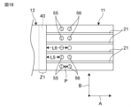
- FIG. 18 is a plan view illustrating a fifth embodiment of the elastic device.
- four first wirings 21 were formed on the first base material 11 .
- Holes 55 and 56 having a diameter of 1.0 mm were formed in the first base material 11 .
- Five holes 55 and 56 are arranged in the second direction B to form a set, and for example, a plurality of such sets are arranged in the first direction A.
- five holes 55 in the first row and five holes 56 in the second row were formed in order from the position closer to the connection region Z1.
- the shortest distance L5 from the connection region Z1 (connection member 40) to the five holes 55 in the first row was set to 3.0 mm.
- the first base material 11 was stretched twice in the first direction A.
- the first substrate 11 was calculated for the unit displacement in the vicinity of the connection region Z1.
- the shortest distance L6 from the connection region Z1 to the five holes 56 in the second row is 4.5 mm
- the shortest distance from the connection region Z1 to the five holes 56 in the third row is 6.0 mm
- the distance from the connection region Z1 The shortest distance to the five holes in the fourth row was set to 7.5 mm
- the shortest distance from the connection region Z1 to the five holes in the fifth row was set to 9.5 mm. That is, the interval P between the holes adjacent to each other in the first direction A was set to 0.5 mm.
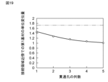
- FIG. 19 the horizontal axis indicates the number of rows of holes, and the vertical axis indicates the unit displacement amount of the first base member 11 near the connection region Z1.
- a two-dot chain line indicates a case without a hole.
- FIG. 19 by increasing the number of rows of holes, the amount of unit displacement of the first base material 11 near the connection area Z1 is reduced, and the first base material 11 near the connection area Z1 It was confirmed that the elongation of In particular, it can be seen that the holes in the first, second, and third rows greatly contribute to the reduction in elongation of the first base material 11 near the connection region Z1.
- the extension amount of the elastic device was measured when the wiring (first wiring or second wiring) was broken in the vicinity of the connection area.
- the third example four wires containing silver were printed on each of the first base material and the second base material with a dispenser.
- the wiring width was 0.5 mm
- the wiring length was 15 mm
- the wiring interval was 1 mm.
- the first base material and the second base material were joined by a connecting member (ACF).
- Five holes with a diameter of 0.7 mm were formed in each of the first base material and the second base material by laser processing. The five holes were arranged in a row in a direction orthogonal to the first direction. The shortest distance from the connection area (connection member) to the hole was set to 3.0 mm.
- the fifth example four wires containing silver were printed on each of the first base material and the second base material with a dispenser.
- the wiring width was 0.5 mm
- the wiring length was 15 mm
- the wiring interval was 1 mm.
- the first base material and the second base material were joined by a connecting member (ACF).
- a hole having a diameter of 0.7 mm was formed in each of the first base material and the second base material by laser processing.
- Four rows of five holes were formed. The shortest distance from the connection area to the hole in the first row is 3.0 mm
- the shortest distance from the connection area to the hole in the second row is 4.5 mm
- the shortest distance from the connection area to the hole in the third row is 5.5 mm.
- first comparative example four wires containing silver were printed on each of the first base material and the second base material with a dispenser.
- the wiring width was 0.5 mm
- the wiring length was 15 mm
- the wiring interval was 0.5 mm.
- the first base material and the second base material were joined by a connecting member (ACF). Then, the respective ends of the first base material and the second base material were gripped, and the first base material and the second base material were extended by 1 mm each in the first direction until the wiring was broken. As a result, disconnection was confirmed when the first base material and the second base material were stretched by 18 mm.
- connection member As a second comparative example, four wires containing silver were printed on each of the first base material and the second base material with a dispenser.
- the wiring width was 0.5 mm
- the wiring length was 15 mm
- the wiring interval was 1 mm.
- the first base material and the second base material were joined by a connecting member (ACF).
- Five holes with a diameter of 0.7 mm were formed in each of the first base material and the second base material by laser processing. The five holes were arranged in a row in a direction orthogonal to the first direction.
- the shortest distance from the connection area (connection member) to the hole was set to 0.2 mm.
- FIG. 20 shows the extension amount of the elastic device when the wiring is disconnected near the connection region in each of the third example, the fifth example, the first comparative example, and the second comparative example.
- the expansion amount of the elastic device is larger, and the disconnection of the wiring occurs in the vicinity of the connection region. It turns out that this is becoming less likely.
- the hole 50 corresponding to the first hole described in the claims includes other holes arranged in the first direction with respect to the first hole on the first main surface. Although it is closest to the connection member among the plurality of holes, the present invention is not limited to such a structure, and a different hole 50 is arranged between the hole 50 corresponding to the first hole and the connection member. may have been
- connection member 50 hole Part 50a, 51a, 52a, 53a First hole 50b, 51b, 52b, 53b Second hole 50c, 51c, 52c, 53c Third hole 510a, 520a, 530a Center 55 First row hole 56 Second row hole 60, 60A Protective film 60a Through hole 60b Overlapping part A First direction B Second direction L Shortest distance L1 First shortest distance L2 Second shortest distance L3 Third shortest distance L5 First row hole Shortest distance L6 Shortest distance between holes in second row P Space between holes Z1 Connection area Z2 Non-connection area
Landscapes
- Engineering & Computer Science (AREA)
- Microelectronics & Electronic Packaging (AREA)
- Manufacturing & Machinery (AREA)
- Structure Of Printed Boards (AREA)
Priority Applications (3)
| Application Number | Priority Date | Filing Date | Title |
|---|---|---|---|
| JP2023562145A JP7605343B2 (ja) | 2021-11-19 | 2022-08-26 | 伸縮デバイス |
| CN202280060681.3A CN117981475A (zh) | 2021-11-19 | 2022-08-26 | 伸缩器件 |
| US18/435,032 US12526915B2 (en) | 2021-11-19 | 2024-02-07 | Stretchable device |
Applications Claiming Priority (2)
| Application Number | Priority Date | Filing Date | Title |
|---|---|---|---|
| JP2021188854 | 2021-11-19 | ||
| JP2021-188854 | 2021-11-19 |
Related Child Applications (1)
| Application Number | Title | Priority Date | Filing Date |
|---|---|---|---|
| US18/435,032 Continuation US12526915B2 (en) | 2021-11-19 | 2024-02-07 | Stretchable device |
Publications (1)
| Publication Number | Publication Date |
|---|---|
| WO2023089897A1 true WO2023089897A1 (ja) | 2023-05-25 |
Family
ID=86396637
Family Applications (1)
| Application Number | Title | Priority Date | Filing Date |
|---|---|---|---|
| PCT/JP2022/032254 Ceased WO2023089897A1 (ja) | 2021-11-19 | 2022-08-26 | 伸縮デバイス |
Country Status (4)
| Country | Link |
|---|---|
| US (1) | US12526915B2 (cg-RX-API-DMAC7.html) |
| JP (1) | JP7605343B2 (cg-RX-API-DMAC7.html) |
| CN (1) | CN117981475A (cg-RX-API-DMAC7.html) |
| WO (1) | WO2023089897A1 (cg-RX-API-DMAC7.html) |
Families Citing this family (1)
| Publication number | Priority date | Publication date | Assignee | Title |
|---|---|---|---|---|
| WO2023171294A1 (ja) * | 2022-03-08 | 2023-09-14 | 株式会社村田製作所 | 伸縮性デバイス |
Citations (6)
| Publication number | Priority date | Publication date | Assignee | Title |
|---|---|---|---|---|
| JP2012033597A (ja) * | 2010-07-29 | 2012-02-16 | Tokai Rubber Ind Ltd | 配線体接続構造体 |
| JP2018056321A (ja) * | 2016-09-28 | 2018-04-05 | 日本メクトロン株式会社 | 伸縮性配線基板及び伸縮性配線基板の製造方法 |
| JP2019075420A (ja) * | 2017-10-12 | 2019-05-16 | 大日本印刷株式会社 | 配線基板 |
| WO2020091012A1 (ja) * | 2018-10-31 | 2020-05-07 | 大日本印刷株式会社 | 配線基板及び配線基板の製造方法 |
| WO2020262288A1 (ja) * | 2019-06-27 | 2020-12-30 | パナソニックIpマネジメント株式会社 | 伸縮性回路基板、及び伸縮性回路実装品 |
| JP2021057506A (ja) * | 2019-09-30 | 2021-04-08 | 大日本印刷株式会社 | 配線基板 |
Family Cites Families (6)
| Publication number | Priority date | Publication date | Assignee | Title |
|---|---|---|---|---|
| JP2008108909A (ja) | 2006-10-25 | 2008-05-08 | Sharp Corp | フレキシブル配線基板の接続構造、および、電子機器 |
| TWI342063B (en) | 2007-06-08 | 2011-05-11 | Ind Tech Res Inst | A bonding structure of flexible films and bonding method therefor |
| JP5823879B2 (ja) | 2012-01-16 | 2015-11-25 | 日本メクトロン株式会社 | フレキシブル回路基板 |
| JP2018066933A (ja) * | 2016-10-21 | 2018-04-26 | 株式会社ジャパンディスプレイ | 表示装置 |
| JP2018129412A (ja) * | 2017-02-09 | 2018-08-16 | ソニーセミコンダクタソリューションズ株式会社 | 半導体装置、および半導体装置の製造方法 |
| JP7249512B2 (ja) | 2018-11-30 | 2023-03-31 | 大日本印刷株式会社 | 配線基板及び配線基板の製造方法 |
-
2022
- 2022-08-26 JP JP2023562145A patent/JP7605343B2/ja active Active
- 2022-08-26 WO PCT/JP2022/032254 patent/WO2023089897A1/ja not_active Ceased
- 2022-08-26 CN CN202280060681.3A patent/CN117981475A/zh active Pending
-
2024
- 2024-02-07 US US18/435,032 patent/US12526915B2/en active Active
Patent Citations (6)
| Publication number | Priority date | Publication date | Assignee | Title |
|---|---|---|---|---|
| JP2012033597A (ja) * | 2010-07-29 | 2012-02-16 | Tokai Rubber Ind Ltd | 配線体接続構造体 |
| JP2018056321A (ja) * | 2016-09-28 | 2018-04-05 | 日本メクトロン株式会社 | 伸縮性配線基板及び伸縮性配線基板の製造方法 |
| JP2019075420A (ja) * | 2017-10-12 | 2019-05-16 | 大日本印刷株式会社 | 配線基板 |
| WO2020091012A1 (ja) * | 2018-10-31 | 2020-05-07 | 大日本印刷株式会社 | 配線基板及び配線基板の製造方法 |
| WO2020262288A1 (ja) * | 2019-06-27 | 2020-12-30 | パナソニックIpマネジメント株式会社 | 伸縮性回路基板、及び伸縮性回路実装品 |
| JP2021057506A (ja) * | 2019-09-30 | 2021-04-08 | 大日本印刷株式会社 | 配線基板 |
Also Published As
| Publication number | Publication date |
|---|---|
| US20240179835A1 (en) | 2024-05-30 |
| JPWO2023089897A1 (cg-RX-API-DMAC7.html) | 2023-05-25 |
| JP7605343B2 (ja) | 2024-12-24 |
| CN117981475A (zh) | 2024-05-03 |
| US12526915B2 (en) | 2026-01-13 |
Similar Documents
| Publication | Publication Date | Title |
|---|---|---|
| US11658376B2 (en) | Signal transmission line including a flexible resin laminate having interior hollow portions overlapping the signal transmission line with the hollow portions having a vent hole | |
| US10575399B2 (en) | Multilayer substrate | |
| JP5752727B2 (ja) | 部品実装フレキシブルプリント基板 | |
| WO2021095620A1 (ja) | 伝送線路及び電子機器 | |
| CN119318210A (zh) | 伸缩性器件 | |
| WO2019142388A1 (ja) | 伸縮配線部材 | |
| US12526915B2 (en) | Stretchable device | |
| JP7718604B2 (ja) | 伸縮性デバイス | |
| JP5527493B1 (ja) | フラットケーブルおよび電子機器 | |
| WO2023171464A1 (ja) | 伸縮性デバイス | |
| WO2024004783A1 (ja) | 伸縮デバイス | |
| US10128588B2 (en) | Cable connecting structure | |
| CN106030910A (zh) | 布线构件 | |
| JP2009224617A (ja) | 配線基板 | |
| JP7622704B2 (ja) | 伸縮性デバイス | |
| JP6975422B2 (ja) | 配線基板 | |
| JP2011108922A (ja) | 回路基板 | |
| JP7563632B2 (ja) | 伸縮配線基板 | |
| CN110012594A (zh) | 一种柔性电路板及终端设备 | |
| JP7758216B2 (ja) | 伸縮性デバイス | |
| JP7443875B2 (ja) | 伸縮性電子部品及び伸縮性電子部品実装基板 | |
| JP7540611B2 (ja) | 伸縮デバイス | |
| JP7613632B2 (ja) | 伸縮性デバイス | |
| JP3871972B2 (ja) | テープキャリアおよびそれを用いた電子機器 | |
| WO2026048693A1 (ja) | 伸縮性デバイス |
Legal Events
| Date | Code | Title | Description |
|---|---|---|---|
| 121 | Ep: the epo has been informed by wipo that ep was designated in this application |
Ref document number: 22895185 Country of ref document: EP Kind code of ref document: A1 |
|
| WWE | Wipo information: entry into national phase |
Ref document number: 2023562145 Country of ref document: JP |
|
| WWE | Wipo information: entry into national phase |
Ref document number: 202280060681.3 Country of ref document: CN |
|
| NENP | Non-entry into the national phase |
Ref country code: DE |
|
| 122 | Ep: pct application non-entry in european phase |
Ref document number: 22895185 Country of ref document: EP Kind code of ref document: A1 |