WO2023079697A1 - プロペラファン、送風機および空気調和機 - Google Patents
プロペラファン、送風機および空気調和機 Download PDFInfo
- Publication number
- WO2023079697A1 WO2023079697A1 PCT/JP2021/040839 JP2021040839W WO2023079697A1 WO 2023079697 A1 WO2023079697 A1 WO 2023079697A1 JP 2021040839 W JP2021040839 W JP 2021040839W WO 2023079697 A1 WO2023079697 A1 WO 2023079697A1
- Authority
- WO
- WIPO (PCT)
- Prior art keywords
- trajectory
- propeller fan
- wing
- blade
- region
- Prior art date
- Legal status (The legal status is an assumption and is not a legal conclusion. Google has not performed a legal analysis and makes no representation as to the accuracy of the status listed.)
- Ceased
Links
Images


Classifications
-
- F—MECHANICAL ENGINEERING; LIGHTING; HEATING; WEAPONS; BLASTING
- F04—POSITIVE - DISPLACEMENT MACHINES FOR LIQUIDS; PUMPS FOR LIQUIDS OR ELASTIC FLUIDS
- F04D—NON-POSITIVE-DISPLACEMENT PUMPS
- F04D29/00—Details, component parts, or accessories
- F04D29/26—Rotors specially for elastic fluids
- F04D29/32—Rotors specially for elastic fluids for axial flow pumps
- F04D29/38—Blades
- F04D29/384—Blades characterised by form
- F04D29/386—Skewed blades
-
- F—MECHANICAL ENGINEERING; LIGHTING; HEATING; WEAPONS; BLASTING
- F04—POSITIVE - DISPLACEMENT MACHINES FOR LIQUIDS; PUMPS FOR LIQUIDS OR ELASTIC FLUIDS
- F04D—NON-POSITIVE-DISPLACEMENT PUMPS
- F04D29/00—Details, component parts, or accessories
- F04D29/40—Casings; Connections of working fluid
- F04D29/52—Casings; Connections of working fluid for axial pumps
- F04D29/522—Casings; Connections of working fluid for axial pumps especially adapted for elastic fluid pumps
- F04D29/526—Details of the casing section radially opposing blade tips
-
- F—MECHANICAL ENGINEERING; LIGHTING; HEATING; WEAPONS; BLASTING
- F05—INDEXING SCHEMES RELATING TO ENGINES OR PUMPS IN VARIOUS SUBCLASSES OF CLASSES F01-F04
- F05D—INDEXING SCHEME FOR ASPECTS RELATING TO NON-POSITIVE-DISPLACEMENT MACHINES OR ENGINES, GAS-TURBINES OR JET-PROPULSION PLANTS
- F05D2240/00—Components
- F05D2240/20—Rotors
- F05D2240/30—Characteristics of rotor blades, i.e. of any element transforming dynamic fluid energy to or from rotational energy and being attached to a rotor
- F05D2240/303—Characteristics of rotor blades, i.e. of any element transforming dynamic fluid energy to or from rotational energy and being attached to a rotor related to the leading edge of a rotor blade
-
- F—MECHANICAL ENGINEERING; LIGHTING; HEATING; WEAPONS; BLASTING
- F05—INDEXING SCHEMES RELATING TO ENGINES OR PUMPS IN VARIOUS SUBCLASSES OF CLASSES F01-F04
- F05D—INDEXING SCHEME FOR ASPECTS RELATING TO NON-POSITIVE-DISPLACEMENT MACHINES OR ENGINES, GAS-TURBINES OR JET-PROPULSION PLANTS
- F05D2240/00—Components
- F05D2240/20—Rotors
- F05D2240/30—Characteristics of rotor blades, i.e. of any element transforming dynamic fluid energy to or from rotational energy and being attached to a rotor
- F05D2240/304—Characteristics of rotor blades, i.e. of any element transforming dynamic fluid energy to or from rotational energy and being attached to a rotor related to the trailing edge of a rotor blade
Definitions
- the present disclosure relates to propeller fans, blowers and air conditioners.
- Patent Document 1 describes a propeller fan.
- a propeller fan includes a rotating shaft and blades that rotate about the rotating shaft.
- An object of the present disclosure is to obtain a propeller fan that is advantageous in terms of energy efficiency.
- a propeller fan includes a rotating shaft and blades that rotate about the rotating shaft.
- the first trajectory connecting the leading edge of the blade and the outer peripheral edge of the wing is different from the second trajectory connecting the center of the rotating shaft and the leading edge. It inclines so that the outer peripheral edge side may retreat.
- the third locus connecting the root of the blade and the outer peripheral edge of the blade is different from the fourth locus connecting the center of the rotating shaft and the root.
- the outer peripheral edge side is inclined to recede.
- FIG. 2 is a side view for explaining the propeller fan of Embodiment 1;
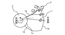
- FIG. 1 is a front view for explaining a propeller fan according to Embodiment 1;
- FIG. FIG. 4 is a diagram showing an application example of the propeller fan in Embodiment 1;
- FIG. 5 is a front view for explaining a first modified example of the propeller fan of Embodiment 1;
- FIG. 8 is a diagram showing an application example of the second modification of the propeller fan of Embodiment 1;
- FIG. 8 is a front view for explaining a second modification of the propeller fan of Embodiment 1;
- FIG. 8 is a front view for explaining a third modification of the propeller fan of Embodiment 1;
- FIG. 1 is a side view illustrating a propeller fan according to Embodiment 1.
- FIG. FIG. 2 is a front view for explaining the propeller fan of Embodiment 1.
- FIG. A propeller fan according to the present disclosure includes a rotating shaft and blades 1 that rotate about the rotating shaft. The axis of rotation is formed as a boss 2 by way of example.
- the propeller fan according to this embodiment is characterized by the shape of the blade 1. Specifically, at the same position in the axial direction of the rotating shaft, a first locus connecting the leading edge 1a of the blade 1 and the outer peripheral edge 1b of the blade 1 connects the center of the rotating shaft and the leading edge 1a.
- the outer peripheral end 1b side is inclined to retreat with respect to the second locus.
- the third trajectory connecting the root 1c of the blade 1 and the outer peripheral edge 1b of the blade 1 at the same position in the axial direction of the rotating shaft becomes the fourth trajectory connecting the center of the rotating shaft and this root 1c.
- the outer peripheral end 1b side is inclined so as to recede.
- Figures 1 and 2 explain the features of the shape described above.
- Lines indicated by symbols A, B and C in FIG. 1 explain "same positions in the axial direction of the rotating shaft".
- the first and third trajectories described above are shown as solid-line trajectories in FIG.
- the second trajectory and the fourth trajectory are shown as dashed trajectories in FIG.
- Code A, code B and code C in FIG. 2 correspond to code A, code B and code C in FIG. 1, respectively.
- the propeller fan according to this embodiment can be applied to any blower, for example.
- a blower is a device that blows air using an airflow generated by a propeller fan.
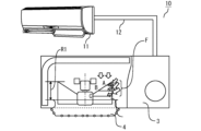
- FIG. 3 is a diagram showing an application example of the propeller fan of Embodiment 1.
- the propeller fan according to the present embodiment can be provided in the outdoor unit 3 of the air conditioner 10, for example.
- the air conditioner 10 includes an indoor unit 11 that blows air into the room, and an outdoor unit 3 that is connected to the indoor unit 11 by a pipe 12 .
- a propeller fan applied to the outdoor unit 3 is covered with, for example, a semi-open bell mouth 4 that does not cover the upstream side of the propeller fan. Even when the propeller fan is applied to a device other than the outdoor unit 3, it can be used while being covered by the half-open bell mouth 4.
- a half-open bell mouth 4 covers part of the wing 1.
- a region where the wing 1 is not covered by the bell mouth that is, a region R1 where the wing 1 and the bell mouth 4 do not overlap
- a large flow F from the fan side surface to the wing 1 can occur. Therefore, it is desirable that the inclination of the first trajectory with respect to the second trajectory is formed at least in the region R1 where the bell mouth 4 and the wing 1 do not overlap.
- the inclination of the third trajectory with respect to the fourth trajectory is desirably formed at least in the region R1 where the bell mouth 4 and the wing 1 do not overlap.
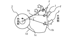
- FIG. 4 is a front view for explaining a first modified example of the propeller fan of Embodiment 1.
- FIG. 4 In general, the flow F from the fan side surface, which has a radial component, tends to increase toward the downstream side, that is, toward the trailing edge 1 d side of the blade 1 . Therefore, as shown in FIG. 4, the inclination of the above-described first trajectory with respect to the second trajectory may be increased toward the trailing edge 1d side of the blade 1.
- the inclination of the third trajectory with respect to the fourth trajectory may be increased toward the trailing edge 1 d side of the blade 1 .
- the slope of the third trajectory with respect to the fourth trajectory may be greater than the slope of the first trajectory with respect to the second trajectory.
- the inclination of the first trajectory with respect to the second trajectory does not necessarily have to increase toward the trailing edge 1d side of the blade 1 over the entire area. If there is not a little region where the inclination of the first trajectory with respect to the second trajectory increases toward the trailing edge 1d side of the blade 1, the effect of improving the energy efficiency can be achieved. Similarly, the inclination of the third trajectory with respect to the fourth trajectory does not necessarily have to increase toward the trailing edge 1d side of the blade 1 over the entire area.
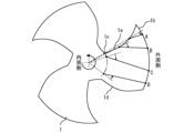
- FIG. 5 is a diagram showing an application example of the second modification of the propeller fan of Embodiment 1.
- FIG. FIG. 6 is a front view for explaining a second modification of the propeller fan of Embodiment 1.
- FIG. Lines denoted by symbols A, B, C and D in FIG. 5 explain "the same position in the axial direction of the rotating shaft", like the lines denoted by respective symbols in FIG. Code A, code B, code C and code D in FIG. 6 respectively correspond to code A, code B, code C and code D in FIG.
- the flow F from the side of the fan is small. Therefore, in the region R2 where the bell mouth 4 and the wing 1 overlap, the backward inclination of the first trajectory with respect to the second trajectory is made smaller than in the region R1 where the bell mouth 4 and the wing 1 do not overlap. good too.
- the backward inclination of the third trajectory with respect to the fourth trajectory is made smaller than in the region R1 where the bell mouth 4 and the wing 1 do not overlap. good too.
- the backward inclination of the third trajectory in the region R2 where the bell mouth 4 and the wing 1 overlap with respect to the fourth trajectory is compared with the inclination of the first trajectory in the region R1 where the bell mouth 4 and the wing 1 do not overlap. 2 may be less than the backward tilt for the trajectory. According to this configuration, it is possible to provide a propeller fan that is more energy efficient.
- the third trajectory is tilted with respect to the fourth trajectory so that the outer peripheral end side of the wing 1 moves forward.
- the first trajectory may be inclined with respect to the second trajectory so that the outer peripheral end side of the wing 1 moves forward.
- FIG. 7 is a front view for explaining a third modification of the propeller fan of Embodiment 1.
- the propeller fan according to the present disclosure can also be applied to a bossless configuration in which blades 1 are directly and integrally connected without bosses 2, for example.
- the axis of rotation is formed in the central portion of the integrally connected blades 1 .
- the propeller fan according to the present disclosure can be used for various blowers or outdoor units of air conditioners.
Landscapes
- Engineering & Computer Science (AREA)
- Mechanical Engineering (AREA)
- General Engineering & Computer Science (AREA)
- Structures Of Non-Positive Displacement Pumps (AREA)
Priority Applications (5)
| Application Number | Priority Date | Filing Date | Title |
|---|---|---|---|
| PCT/JP2021/040839 WO2023079697A1 (ja) | 2021-11-05 | 2021-11-05 | プロペラファン、送風機および空気調和機 |
| CN202180103733.6A CN118251548A (zh) | 2021-11-05 | 2021-11-05 | 螺旋桨式风扇、送风机以及空调机 |
| EP21963292.4A EP4428374A4 (en) | 2021-11-05 | 2021-11-05 | PROPELLER FANS, BLOWER AND AIR CONDITIONING |
| US18/687,560 US12270411B2 (en) | 2021-11-05 | 2021-11-05 | Propeller fan, blower, and air conditioner |
| JP2023557553A JP7568133B2 (ja) | 2021-11-05 | 2021-11-05 | プロペラファン、送風機および空気調和機 |
Applications Claiming Priority (1)
| Application Number | Priority Date | Filing Date | Title |
|---|---|---|---|
| PCT/JP2021/040839 WO2023079697A1 (ja) | 2021-11-05 | 2021-11-05 | プロペラファン、送風機および空気調和機 |
Publications (1)
| Publication Number | Publication Date |
|---|---|
| WO2023079697A1 true WO2023079697A1 (ja) | 2023-05-11 |
Family
ID=86240908
Family Applications (1)
| Application Number | Title | Priority Date | Filing Date |
|---|---|---|---|
| PCT/JP2021/040839 Ceased WO2023079697A1 (ja) | 2021-11-05 | 2021-11-05 | プロペラファン、送風機および空気調和機 |
Country Status (5)
| Country | Link |
|---|---|
| US (1) | US12270411B2 (https=) |
| EP (1) | EP4428374A4 (https=) |
| JP (1) | JP7568133B2 (https=) |
| CN (1) | CN118251548A (https=) |
| WO (1) | WO2023079697A1 (https=) |
Citations (3)
| Publication number | Priority date | Publication date | Assignee | Title |
|---|---|---|---|---|
| JPH11201084A (ja) * | 1998-01-08 | 1999-07-27 | Matsushita Electric Ind Co Ltd | 送風装置 |
| JP2006233886A (ja) * | 2005-02-25 | 2006-09-07 | Mitsubishi Electric Corp | プロペラファン |
| WO2009130954A1 (ja) * | 2008-04-22 | 2009-10-29 | 三菱電機株式会社 | 送風機およびこの送風機を用いたヒートポンプ装置 |
Family Cites Families (5)
| Publication number | Priority date | Publication date | Assignee | Title |
|---|---|---|---|---|
| JPS62282198A (ja) | 1986-05-30 | 1987-12-08 | Mitsubishi Electric Corp | 軸流フアン |
| JP4190683B2 (ja) * | 1999-11-22 | 2008-12-03 | 株式会社小松製作所 | ファン装置 |
| JP3629702B2 (ja) | 2001-12-21 | 2005-03-16 | ダイキン工業株式会社 | 送風機 |
| JP4467952B2 (ja) | 2003-11-10 | 2010-05-26 | 東芝キヤリア株式会社 | プロペラファン、これを用いた空気調和機用室外ユニット |
| JP6719641B2 (ja) * | 2017-02-28 | 2020-07-08 | 三菱電機株式会社 | プロペラファン、送風機及び空気調和機 |
-
2021
- 2021-11-05 US US18/687,560 patent/US12270411B2/en active Active
- 2021-11-05 CN CN202180103733.6A patent/CN118251548A/zh not_active Withdrawn
- 2021-11-05 WO PCT/JP2021/040839 patent/WO2023079697A1/ja not_active Ceased
- 2021-11-05 EP EP21963292.4A patent/EP4428374A4/en not_active Withdrawn
- 2021-11-05 JP JP2023557553A patent/JP7568133B2/ja active Active
Patent Citations (3)
| Publication number | Priority date | Publication date | Assignee | Title |
|---|---|---|---|---|
| JPH11201084A (ja) * | 1998-01-08 | 1999-07-27 | Matsushita Electric Ind Co Ltd | 送風装置 |
| JP2006233886A (ja) * | 2005-02-25 | 2006-09-07 | Mitsubishi Electric Corp | プロペラファン |
| WO2009130954A1 (ja) * | 2008-04-22 | 2009-10-29 | 三菱電機株式会社 | 送風機およびこの送風機を用いたヒートポンプ装置 |
Non-Patent Citations (1)
| Title |
|---|
| See also references of EP4428374A4 * |
Also Published As
| Publication number | Publication date |
|---|---|
| CN118251548A (zh) | 2024-06-25 |
| US12270411B2 (en) | 2025-04-08 |
| US20250003420A1 (en) | 2025-01-02 |
| EP4428374A4 (en) | 2025-01-01 |
| EP4428374A1 (en) | 2024-09-11 |
| JP7568133B2 (ja) | 2024-10-16 |
| JPWO2023079697A1 (https=) | 2023-05-11 |
Similar Documents
| Publication | Publication Date | Title |
|---|---|---|
| JP3960776B2 (ja) | 空調用送風機羽根車 | |
| JP6656372B2 (ja) | 軸流送風機 | |
| JP2008507652A (ja) | 増大した流量を有する軸流インペラ | |
| JP6771562B2 (ja) | プロペラファンおよび流体送り装置 | |
| JPH08240197A (ja) | 軸流ファン | |
| JP2019019759A (ja) | 遠心ファンインペラおよび当該遠心ファンインペラを備える遠心ファン | |
| JP2019019758A (ja) | 遠心ファンインペラおよび当該遠心ファンインペラを備える遠心ファン | |
| JP3629690B2 (ja) | 多翼送風機 | |
| JP6929453B2 (ja) | 送風装置及び空気調和装置用室外機 | |
| WO2023079697A1 (ja) | プロペラファン、送風機および空気調和機 | |
| JP4680840B2 (ja) | 軸流送風機 | |
| GB2064668A (en) | Fan Blade | |
| JP2753182B2 (ja) | 軸流ファン | |
| JP2001304185A (ja) | 送風機羽根車とその送風機羽根車を備えた空気調和機 | |
| KR100329928B1 (ko) | 분리형 공기조화기의 실외기 | |
| JPWO2023079697A5 (https=) | ||
| JP2019211146A (ja) | 風向変更装置及び送風装置 | |
| JP2022012386A (ja) | 送風装置および空気調和機用室外機 | |
| JP3211645B2 (ja) | ファン | |
| JPH11132196A (ja) | 多翼送風機 | |
| KR100504480B1 (ko) | 축류팬 | |
| JPH06249195A (ja) | 軸流送風機の羽根車 | |
| JPH05340390A (ja) | ファン構造 | |
| JP2006077632A (ja) | 空調用送風機羽根車 | |
| JPH0640957Y2 (ja) | 軸流送風機 |
Legal Events
| Date | Code | Title | Description |
|---|---|---|---|
| 121 | Ep: the epo has been informed by wipo that ep was designated in this application |
Ref document number: 21963292 Country of ref document: EP Kind code of ref document: A1 |
|
| WWE | Wipo information: entry into national phase |
Ref document number: 2023557553 Country of ref document: JP |
|
| WWE | Wipo information: entry into national phase |
Ref document number: 18687560 Country of ref document: US |
|
| WWE | Wipo information: entry into national phase |
Ref document number: 202180103733.6 Country of ref document: CN |
|
| WWE | Wipo information: entry into national phase |
Ref document number: 2021963292 Country of ref document: EP |
|
| ENP | Entry into the national phase |
Ref document number: 2021963292 Country of ref document: EP Effective date: 20240605 |
|
| WWG | Wipo information: grant in national office |
Ref document number: 18687560 Country of ref document: US |
|
| WWW | Wipo information: withdrawn in national office |
Ref document number: 2021963292 Country of ref document: EP |