WO2023068153A1 - 灯具及び車両用前照灯 - Google Patents
灯具及び車両用前照灯 Download PDFInfo
- Publication number
- WO2023068153A1 WO2023068153A1 PCT/JP2022/038169 JP2022038169W WO2023068153A1 WO 2023068153 A1 WO2023068153 A1 WO 2023068153A1 JP 2022038169 W JP2022038169 W JP 2022038169W WO 2023068153 A1 WO2023068153 A1 WO 2023068153A1
- Authority
- WO
- WIPO (PCT)
- Prior art keywords
- light source
- light
- substrate
- reflector
- projection lens
- Prior art date
- Legal status (The legal status is an assumption and is not a legal conclusion. Google has not performed a legal analysis and makes no representation as to the accuracy of the status listed.)
- Ceased
Links
Images













Classifications
-
- F—MECHANICAL ENGINEERING; LIGHTING; HEATING; WEAPONS; BLASTING
- F21—LIGHTING
- F21S—NON-PORTABLE LIGHTING DEVICES; SYSTEMS THEREOF; VEHICLE LIGHTING DEVICES SPECIALLY ADAPTED FOR VEHICLE EXTERIORS
- F21S41/00—Illuminating devices specially adapted for vehicle exteriors, e.g. headlamps
- F21S41/10—Illuminating devices specially adapted for vehicle exteriors, e.g. headlamps characterised by the light source
- F21S41/14—Illuminating devices specially adapted for vehicle exteriors, e.g. headlamps characterised by the light source characterised by the type of light source
- F21S41/141—Light emitting diodes [LED]
- F21S41/143—Light emitting diodes [LED] the main emission direction of the LED being parallel to the optical axis of the illuminating device
-
- F—MECHANICAL ENGINEERING; LIGHTING; HEATING; WEAPONS; BLASTING
- F21—LIGHTING
- F21S—NON-PORTABLE LIGHTING DEVICES; SYSTEMS THEREOF; VEHICLE LIGHTING DEVICES SPECIALLY ADAPTED FOR VEHICLE EXTERIORS
- F21S41/00—Illuminating devices specially adapted for vehicle exteriors, e.g. headlamps
- F21S41/30—Illuminating devices specially adapted for vehicle exteriors, e.g. headlamps characterised by reflectors
- F21S41/39—Attachment thereof
-
- F—MECHANICAL ENGINEERING; LIGHTING; HEATING; WEAPONS; BLASTING
- F21—LIGHTING
- F21S—NON-PORTABLE LIGHTING DEVICES; SYSTEMS THEREOF; VEHICLE LIGHTING DEVICES SPECIALLY ADAPTED FOR VEHICLE EXTERIORS
- F21S41/00—Illuminating devices specially adapted for vehicle exteriors, e.g. headlamps
- F21S41/10—Illuminating devices specially adapted for vehicle exteriors, e.g. headlamps characterised by the light source
- F21S41/14—Illuminating devices specially adapted for vehicle exteriors, e.g. headlamps characterised by the light source characterised by the type of light source
- F21S41/141—Light emitting diodes [LED]
- F21S41/147—Light emitting diodes [LED] the main emission direction of the LED being angled to the optical axis of the illuminating device
-
- F—MECHANICAL ENGINEERING; LIGHTING; HEATING; WEAPONS; BLASTING
- F21—LIGHTING
- F21S—NON-PORTABLE LIGHTING DEVICES; SYSTEMS THEREOF; VEHICLE LIGHTING DEVICES SPECIALLY ADAPTED FOR VEHICLE EXTERIORS
- F21S41/00—Illuminating devices specially adapted for vehicle exteriors, e.g. headlamps
- F21S41/10—Illuminating devices specially adapted for vehicle exteriors, e.g. headlamps characterised by the light source
- F21S41/14—Illuminating devices specially adapted for vehicle exteriors, e.g. headlamps characterised by the light source characterised by the type of light source
- F21S41/141—Light emitting diodes [LED]
- F21S41/151—Light emitting diodes [LED] arranged in one or more lines
-
- F—MECHANICAL ENGINEERING; LIGHTING; HEATING; WEAPONS; BLASTING
- F21—LIGHTING
- F21S—NON-PORTABLE LIGHTING DEVICES; SYSTEMS THEREOF; VEHICLE LIGHTING DEVICES SPECIALLY ADAPTED FOR VEHICLE EXTERIORS
- F21S41/00—Illuminating devices specially adapted for vehicle exteriors, e.g. headlamps
- F21S41/10—Illuminating devices specially adapted for vehicle exteriors, e.g. headlamps characterised by the light source
- F21S41/14—Illuminating devices specially adapted for vehicle exteriors, e.g. headlamps characterised by the light source characterised by the type of light source
- F21S41/141—Light emitting diodes [LED]
- F21S41/151—Light emitting diodes [LED] arranged in one or more lines
- F21S41/153—Light emitting diodes [LED] arranged in one or more lines arranged in a matrix
-
- F—MECHANICAL ENGINEERING; LIGHTING; HEATING; WEAPONS; BLASTING
- F21—LIGHTING
- F21S—NON-PORTABLE LIGHTING DEVICES; SYSTEMS THEREOF; VEHICLE LIGHTING DEVICES SPECIALLY ADAPTED FOR VEHICLE EXTERIORS
- F21S41/00—Illuminating devices specially adapted for vehicle exteriors, e.g. headlamps
- F21S41/10—Illuminating devices specially adapted for vehicle exteriors, e.g. headlamps characterised by the light source
- F21S41/19—Attachment of light sources or lamp holders
- F21S41/192—Details of lamp holders, terminals or connectors
-
- F—MECHANICAL ENGINEERING; LIGHTING; HEATING; WEAPONS; BLASTING
- F21—LIGHTING
- F21S—NON-PORTABLE LIGHTING DEVICES; SYSTEMS THEREOF; VEHICLE LIGHTING DEVICES SPECIALLY ADAPTED FOR VEHICLE EXTERIORS
- F21S41/00—Illuminating devices specially adapted for vehicle exteriors, e.g. headlamps
- F21S41/20—Illuminating devices specially adapted for vehicle exteriors, e.g. headlamps characterised by refractors, transparent cover plates, light guides or filters
- F21S41/25—Projection lenses
- F21S41/255—Lenses with a front view of circular or truncated circular outline
-
- F—MECHANICAL ENGINEERING; LIGHTING; HEATING; WEAPONS; BLASTING
- F21—LIGHTING
- F21S—NON-PORTABLE LIGHTING DEVICES; SYSTEMS THEREOF; VEHICLE LIGHTING DEVICES SPECIALLY ADAPTED FOR VEHICLE EXTERIORS
- F21S41/00—Illuminating devices specially adapted for vehicle exteriors, e.g. headlamps
- F21S41/20—Illuminating devices specially adapted for vehicle exteriors, e.g. headlamps characterised by refractors, transparent cover plates, light guides or filters
- F21S41/25—Projection lenses
- F21S41/26—Elongated lenses
-
- F—MECHANICAL ENGINEERING; LIGHTING; HEATING; WEAPONS; BLASTING
- F21—LIGHTING
- F21S—NON-PORTABLE LIGHTING DEVICES; SYSTEMS THEREOF; VEHICLE LIGHTING DEVICES SPECIALLY ADAPTED FOR VEHICLE EXTERIORS
- F21S41/00—Illuminating devices specially adapted for vehicle exteriors, e.g. headlamps
- F21S41/20—Illuminating devices specially adapted for vehicle exteriors, e.g. headlamps characterised by refractors, transparent cover plates, light guides or filters
- F21S41/29—Attachment thereof
- F21S41/295—Attachment thereof specially adapted to projection lenses
-
- F—MECHANICAL ENGINEERING; LIGHTING; HEATING; WEAPONS; BLASTING
- F21—LIGHTING
- F21S—NON-PORTABLE LIGHTING DEVICES; SYSTEMS THEREOF; VEHICLE LIGHTING DEVICES SPECIALLY ADAPTED FOR VEHICLE EXTERIORS
- F21S41/00—Illuminating devices specially adapted for vehicle exteriors, e.g. headlamps
- F21S41/30—Illuminating devices specially adapted for vehicle exteriors, e.g. headlamps characterised by reflectors
- F21S41/32—Optical layout thereof
- F21S41/321—Optical layout thereof the reflector being a surface of revolution or a planar surface, e.g. truncated
-
- F—MECHANICAL ENGINEERING; LIGHTING; HEATING; WEAPONS; BLASTING
- F21—LIGHTING
- F21S—NON-PORTABLE LIGHTING DEVICES; SYSTEMS THEREOF; VEHICLE LIGHTING DEVICES SPECIALLY ADAPTED FOR VEHICLE EXTERIORS
- F21S41/00—Illuminating devices specially adapted for vehicle exteriors, e.g. headlamps
- F21S41/30—Illuminating devices specially adapted for vehicle exteriors, e.g. headlamps characterised by reflectors
- F21S41/32—Optical layout thereof
- F21S41/323—Optical layout thereof the reflector having two perpendicular cross sections having regular geometrical curves of a distinct nature
-
- F—MECHANICAL ENGINEERING; LIGHTING; HEATING; WEAPONS; BLASTING
- F21—LIGHTING
- F21S—NON-PORTABLE LIGHTING DEVICES; SYSTEMS THEREOF; VEHICLE LIGHTING DEVICES SPECIALLY ADAPTED FOR VEHICLE EXTERIORS
- F21S41/00—Illuminating devices specially adapted for vehicle exteriors, e.g. headlamps
- F21S41/30—Illuminating devices specially adapted for vehicle exteriors, e.g. headlamps characterised by reflectors
- F21S41/32—Optical layout thereof
- F21S41/36—Combinations of two or more separate reflectors
-
- F—MECHANICAL ENGINEERING; LIGHTING; HEATING; WEAPONS; BLASTING
- F21—LIGHTING
- F21S—NON-PORTABLE LIGHTING DEVICES; SYSTEMS THEREOF; VEHICLE LIGHTING DEVICES SPECIALLY ADAPTED FOR VEHICLE EXTERIORS
- F21S41/00—Illuminating devices specially adapted for vehicle exteriors, e.g. headlamps
- F21S41/30—Illuminating devices specially adapted for vehicle exteriors, e.g. headlamps characterised by reflectors
- F21S41/32—Optical layout thereof
- F21S41/36—Combinations of two or more separate reflectors
- F21S41/365—Combinations of two or more separate reflectors successively reflecting the light
-
- F—MECHANICAL ENGINEERING; LIGHTING; HEATING; WEAPONS; BLASTING
- F21—LIGHTING
- F21S—NON-PORTABLE LIGHTING DEVICES; SYSTEMS THEREOF; VEHICLE LIGHTING DEVICES SPECIALLY ADAPTED FOR VEHICLE EXTERIORS
- F21S41/00—Illuminating devices specially adapted for vehicle exteriors, e.g. headlamps
- F21S41/40—Illuminating devices specially adapted for vehicle exteriors, e.g. headlamps characterised by screens, non-reflecting members, light-shielding members or fixed shades
- F21S41/43—Illuminating devices specially adapted for vehicle exteriors, e.g. headlamps characterised by screens, non-reflecting members, light-shielding members or fixed shades characterised by the shape thereof
-
- F—MECHANICAL ENGINEERING; LIGHTING; HEATING; WEAPONS; BLASTING
- F21—LIGHTING
- F21S—NON-PORTABLE LIGHTING DEVICES; SYSTEMS THEREOF; VEHICLE LIGHTING DEVICES SPECIALLY ADAPTED FOR VEHICLE EXTERIORS
- F21S41/00—Illuminating devices specially adapted for vehicle exteriors, e.g. headlamps
- F21S41/60—Illuminating devices specially adapted for vehicle exteriors, e.g. headlamps characterised by a variable light distribution
- F21S41/65—Illuminating devices specially adapted for vehicle exteriors, e.g. headlamps characterised by a variable light distribution by acting on light sources
- F21S41/663—Illuminating devices specially adapted for vehicle exteriors, e.g. headlamps characterised by a variable light distribution by acting on light sources by switching light sources
-
- F—MECHANICAL ENGINEERING; LIGHTING; HEATING; WEAPONS; BLASTING
- F21—LIGHTING
- F21S—NON-PORTABLE LIGHTING DEVICES; SYSTEMS THEREOF; VEHICLE LIGHTING DEVICES SPECIALLY ADAPTED FOR VEHICLE EXTERIORS
- F21S45/00—Arrangements within vehicle lighting devices specially adapted for vehicle exteriors, for purposes other than emission or distribution of light
- F21S45/10—Protection of lighting devices
-
- F—MECHANICAL ENGINEERING; LIGHTING; HEATING; WEAPONS; BLASTING
- F21—LIGHTING
- F21S—NON-PORTABLE LIGHTING DEVICES; SYSTEMS THEREOF; VEHICLE LIGHTING DEVICES SPECIALLY ADAPTED FOR VEHICLE EXTERIORS
- F21S45/00—Arrangements within vehicle lighting devices specially adapted for vehicle exteriors, for purposes other than emission or distribution of light
- F21S45/40—Cooling of lighting devices
- F21S45/42—Forced cooling
- F21S45/43—Forced cooling using gas
- F21S45/435—Forced cooling using gas circulating the gas within a closed system
-
- F—MECHANICAL ENGINEERING; LIGHTING; HEATING; WEAPONS; BLASTING
- F21—LIGHTING
- F21S—NON-PORTABLE LIGHTING DEVICES; SYSTEMS THEREOF; VEHICLE LIGHTING DEVICES SPECIALLY ADAPTED FOR VEHICLE EXTERIORS
- F21S45/00—Arrangements within vehicle lighting devices specially adapted for vehicle exteriors, for purposes other than emission or distribution of light
- F21S45/40—Cooling of lighting devices
- F21S45/47—Passive cooling, e.g. using fins, thermal conductive elements or openings
-
- F—MECHANICAL ENGINEERING; LIGHTING; HEATING; WEAPONS; BLASTING
- F21—LIGHTING
- F21S—NON-PORTABLE LIGHTING DEVICES; SYSTEMS THEREOF; VEHICLE LIGHTING DEVICES SPECIALLY ADAPTED FOR VEHICLE EXTERIORS
- F21S45/00—Arrangements within vehicle lighting devices specially adapted for vehicle exteriors, for purposes other than emission or distribution of light
- F21S45/40—Cooling of lighting devices
- F21S45/49—Attachment of the cooling means
-
- F—MECHANICAL ENGINEERING; LIGHTING; HEATING; WEAPONS; BLASTING
- F21—LIGHTING
- F21W—INDEXING SCHEME ASSOCIATED WITH SUBCLASSES F21K, F21L, F21S and F21V, RELATING TO USES OR APPLICATIONS OF LIGHTING DEVICES OR SYSTEMS
- F21W2102/00—Exterior vehicle lighting devices for illuminating purposes
- F21W2102/10—Arrangement or contour of the emitted light
- F21W2102/13—Arrangement or contour of the emitted light for high-beam region or low-beam region
-
- F—MECHANICAL ENGINEERING; LIGHTING; HEATING; WEAPONS; BLASTING
- F21—LIGHTING
- F21W—INDEXING SCHEME ASSOCIATED WITH SUBCLASSES F21K, F21L, F21S and F21V, RELATING TO USES OR APPLICATIONS OF LIGHTING DEVICES OR SYSTEMS
- F21W2102/00—Exterior vehicle lighting devices for illuminating purposes
- F21W2102/10—Arrangement or contour of the emitted light
- F21W2102/13—Arrangement or contour of the emitted light for high-beam region or low-beam region
- F21W2102/135—Arrangement or contour of the emitted light for high-beam region or low-beam region the light having cut-off lines, i.e. clear borderlines between emitted regions and dark regions
- F21W2102/155—Arrangement or contour of the emitted light for high-beam region or low-beam region the light having cut-off lines, i.e. clear borderlines between emitted regions and dark regions having inclined and horizontal cutoff lines
-
- F—MECHANICAL ENGINEERING; LIGHTING; HEATING; WEAPONS; BLASTING
- F21—LIGHTING
- F21Y—INDEXING SCHEME ASSOCIATED WITH SUBCLASSES F21K, F21L, F21S and F21V, RELATING TO THE FORM OR THE KIND OF THE LIGHT SOURCES OR OF THE COLOUR OF THE LIGHT EMITTED
- F21Y2115/00—Light-generating elements of semiconductor light sources
- F21Y2115/10—Light-emitting diodes [LED]
Definitions
- the present invention relates to a lamp and a vehicle headlamp.
- Patent Document 1 discloses such a lamp.
- the lamp of Patent Document 1 below includes a substrate on which a light source is mounted, a heat sink on which the substrate is arranged, and a reflector unit.
- the reflector unit reflects part of the light emitted from the light source so as to form a predetermined light distribution pattern.
- the substrate is fixed to the heat sink by the reflector unit pressing a plurality of portions of the substrate to press the substrate against the heat sink.
- the lighting device disclosed in Patent Document 1 below is a vehicle headlamp, and includes a first light source, a second light source arranged below the first light source, a reflector unit arranged in front of a substrate, and a reflector unit. a projection lens positioned further forward.
- the reflector unit has a first reflector arranged between the first light source and the second light source, and a pair of second reflectors arranged above and below the first reflector. Part of the light emitted from the first light source passes between the first reflector and the upper second reflector and directly enters the projection lens, and another part of the light enters the projection lens by the upper surface of the first reflector. Another part of the light is reflected by the upper second reflector towards the projection lens.
- the light emitted from the first light source and incident on the projection lens forms a low-beam light distribution pattern having a cutoff line corresponding to the shape of the front end of the first reflector. Also, part of the light emitted from the second light source passes between the first reflector and the lower second reflector and directly enters the projection lens, and the other part of the light passes through the lower surface of the first reflector. It is reflected towards the projection lens and another part of the light is reflected towards the projection lens by the lower second reflector. In this way, the light emitted from the second light source and incident on the projection lens forms an additional light distribution pattern, and the additional light distribution pattern and the low beam light distribution pattern form a high beam light distribution pattern. Therefore, this vehicle headlamp can switch the emitted light between a low beam and a high beam by switching between emission and non-emission of light from the second light source.
- a vehicle headlamp that includes a projection lens that transmits desired light by transmitting light emitted from a light source, and a lens holder that holds the projection lens.
- the lens holder is made of resin, and sunlight entering the vehicle headlight through the projection lens is condensed into the lens holder, thereby suppressing damage to the lens holder.
- a light blocking portion is provided between the projection lens and the lens holder.
- a vehicle headlamp in which a substrate on which a light source is mounted is disposed on a heat sink so that heat generated from the light source is emitted from the heat sink. Lighting is disclosed.
- a substrate on which a light-emitting element array composed of a plurality of LEDs (Light Emitting diodes) is mounted is arranged on a heat sink.
- the rear surface of the substrate where the light emitting element array is mounted is arranged on the convex substrate placement surface of the heat sink. Therefore, heat generated from the light emitting element array is conducted from the light emitting element array through the substrate to the heat sink and released from the heat sink.
- a lamp includes a substrate on which a light source is mounted, a heat sink on which the substrate is arranged, and a reflector unit that presses the substrate against the heat sink and reflects part of the light emitted from the light source. and wherein the substrate has recesses in which side surfaces facing each other are recessed, the light sources are positioned inside the bottoms of the recesses, and the reflector units are arranged in the recesses of the substrate. It is characterized in that a portion outside the bottom of the is pressed.
- the substrate has concave portions in which side surfaces facing each other are concave. For this reason, the strength of the portion of the substrate outside the bottom of each recess is weakened compared to the case where the substrate does not have the recess, and the reflector unit has such a weakened portion. press. For this reason, according to this lamp of the first aspect, the distortion of the substrate due to the pressing force of the reflector unit can be concentrated on the portion where the strength is weakened, and the distortion inside the bottom of the recess can be reduced compared to the above case. can be reduced. In addition, in this lamp of the first aspect, the light source is located inside the bottom of the recess as described above.
- this lamp it is possible to suppress the change in the direction of the light source due to the distortion of the substrate, and to facilitate the formation of a predetermined light distribution pattern, as compared with the above case.
- the reflector unit presses one concave side and the other concave side of the substrate. Therefore, according to the lighting fixture of the first aspect, compared with the case where the reflector unit presses only one concave side of the substrate, it is possible to suppress the displacement of the relative positions of the substrate and the heat sink. It is easy to form a light distribution pattern.
- the reflector unit may press both sides of each recess in the substrate.
- the heat sink may have protrusions that are inserted into the respective recesses.
- the substrate can be positioned with respect to the heat sink by the side surface of the substrate defining the recess and the outer peripheral surface of the protrusion.
- the reflector unit has a flat opposing surface facing the substrate and an opening penetrating from the opposing surface to a surface opposite to the substrate, and the light source extends from the opening. They may overlap.
- the facing surface may extend to the outer edge of the substrate-side surface of the reflector unit.
- the lamp of the first aspect may further include a connector mounted on the substrate, and the reflector unit may not be formed on the side opposite to the light source side from the connector.
- a vehicle headlamp includes a first light source that emits light forming a low-beam light distribution pattern from a planar emission surface; a second light source that emits light forming a light distribution pattern of a high beam from a planar emission surface with light emitted from one light source; a substrate on which the first light source and the second light source are mounted; A reflector unit arranged in front and a projection lens arranged in front of the reflector unit are provided, and the reflector unit is arranged between the first light source and the second light source to reflect both upper and lower surfaces. It has a first reflector which is a plane and a pair of second reflectors arranged above and below the first reflector.
- the first light source and the second light source are mounted on the common substrate, compared to the case where the first light source and the second light source are mounted on different substrates, The number of parts can be reduced.
- the perpendicular to the emission surface of one of the first light source and the second light source corresponds to the emission surface of the first light source and the second light source in the first patent document. , moving forward away from the first reflector. Therefore, the luminous flux of light emitted from one light source and directly incident on the front end portion of one reflecting surface of the first reflector tends to decrease, and it is difficult to brighten the front end portion.
- the vehicle headlamp of the second aspect can suppress the front end portions of the upper and lower surfaces of the first reflector from becoming dark.
- the vehicle headlamp of the second aspect it is possible to suppress the vicinity of the cutoff line in the light distribution pattern of the low beam and the vicinity of the center of the light distribution pattern of the high beam from becoming dark, thereby reducing the visibility. can be suppressed.
- the one light source may be the first light source.
- the other part of the light emitted from the one light source has a smaller divergence angle than when incident on the one second reflector. It may be reflected toward the first reflector.
- the one light source when the one light source is the first light source, it is possible to further suppress darkening in the vicinity of the cutoff line in the light distribution pattern of the low beam, and the one light source is the first light source. In the case of two light sources, it is possible to further suppress darkening in the vicinity of the center of the light distribution pattern of the high beam.
- the other part of the light emitted from the other light source has a larger divergence angle than when incident on the other second reflector. It may be reflected towards the projection lens.
- the light distribution pattern of the high beam can be easily expanded upward, and when the one light source is the second light source, , the light distribution pattern of the low beam can be easily spread downward.
- the vehicle headlamp of the second aspect described above further comprises an integrated circuit mounted on the substrate for adjusting power supplied to at least one of the first light source and the second light source, the reflector unit comprising: and a cover portion covering the integrated circuit.
- a vehicle headlamp comprises: a light source; a reflector unit having a reflecting portion that reflects forward light emitted forward and downward from the light source; a transmitting projection lens; and a conductive member arranged below the reflecting section. It is characterized by having a light-shielding cover positioned between.
- the light shielding member is arranged between the conductive member and the projection lens, it is possible to suppress the irradiation of the conductive member with sunlight incident through the projection lens. can.
- the reflecting portion that reflects the light emitted from the light source usually has a light shielding property. Therefore, by integrating the light-shielding cover and the reflecting portion, both of which have light-shielding properties, it is possible to suppress damage to the conductive member due to sunlight at low cost.
- the vehicle headlamp of the third aspect described above further includes a lens holder having a bottom plate portion extending from the light shielding cover side toward the projection lens side and holding the projection lens, It is preferable that the light-shielding cover includes a plate-like cover portion extending along the extending direction of the bottom plate portion, and at least a part of a side surface of the plate-like cover portion overlaps with the bottom plate portion in the extending direction. .
- the sunlight propagating toward the plate-like cover portion may damage the lens holder. If the plate-like cover portion is placed on the bottom plate portion, the sunlight propagating toward the plate-like cover portion may be reflected by the entire side surface of the plate-like cover portion, and the reflected light may damage the lens holder. Therefore, as described above, at least a part of the side surface of the plate-like cover portion overlaps the bottom plate portion in the extending direction, thereby suppressing damage to the lens holder by sunlight propagating toward the plate-like cover portion. can.
- the width of the bottom plate portion in the left-right direction is larger than that of the plate-like cover portion, and the edge of the bottom plate portion on the side of the plate-like cover portion is formed with a concave portion into which a part of the plate-like cover portion is inserted. preferable.
- a part of the plate-like cover enters the concave portion of the bottom plate portion, thereby suppressing lateral positional deviation between the reflector unit and the lens holder.
- the upper surface of the plate-like cover portion scatters and reflects incident light.
- the light-shielding cover has a light scattering portion that scatters and reflects incident light between the reflecting portion and the plate-like cover portion.
- the plate-shaped cover part and the reflecting part may be separated. According to the above configuration, sunlight propagating between the plate-shaped cover portion and the reflecting portion is scattered, so that it is possible to suppress damage to other members due to reflection of the sunlight.
- the lateral width of the plate-like cover portion is larger than the lateral width of the light scattering portion, and the lateral ends of the plate-like cover portion extend to the rear of the light scattering portion. preferably present.
- the light shielding cover has a side cover portion extending rearward and upward from the rear end of each of the end portions.
- the range of conductive members that can be protected by the light shielding cover can be further widened.
- a vehicle headlamp comprises a substrate on which a light source and an integrated circuit for switching power supply to the light source are mounted, and a heat sink on which the substrate is arranged, wherein the heat sink
- the substrate facing region facing the substrate of includes a separation portion separated from the substrate, and an arrangement portion formed in a convex shape toward the substrate side from the separation portion and in which the substrate is arranged, the arrangement portion comprising: A light source facing area facing the back surface of the area of the substrate where the light source is mounted, an integrated circuit facing area facing the back surface of the area of the substrate where the integrated circuit is mounted, and the light source facing area and the integrated circuit facing area. It is characterized by including a first connection region that connects the regions.
- the heat generated from the light source and the integrated circuit is conducted to the heat sink mainly from the light source facing area and the integrated circuit facing area through the substrate, respectively, thereby dissipating the heat. be done.
- heat generated by the light source and the integrated circuit may be conducted through the substrate, thereby heating the area of the substrate between the area where the light source is mounted and the area where the integrated circuit is mounted.
- the heat in this area can be conducted from the first connection area to the heat sink to dissipate the heat.
- heat conducted to the heat sink can be suppressed from returning from the heat sink to the substrate unnecessarily. Therefore, the vehicle headlamp of the fourth aspect can efficiently radiate heat.
- the light source includes a plurality of light emitting elements arranged in parallel, the light source facing area extends along the parallel direction of the plurality of light emitting elements, and the integrated circuit facing area extends along the light emitting elements located at both ends. It may overlap with a straight line orthogonal to the line segment connecting the elements.
- the extending direction of the light source facing area and the extending direction of the area including the integrated circuit facing area and the first connection area can be orthogonal to each other. Therefore, the substrate can be stably arranged on the heat sink.
- the separation portions are positioned on both sides of the first connection region in the parallel direction.
- the arrangement portion includes an adjustment area extending in the parallel direction over a width wider than the integrated circuit facing area on the side opposite to the light source facing area with respect to the integrated circuit facing area; It is preferable to include a second connection region that connects the region and the integrated circuit facing region.
- the substrate can be stably arranged by the heat sink.
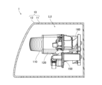
- FIG. 1 is a diagram schematically showing a lighting fixture in a first embodiment as first and second aspects of the present invention
- FIG. 3 is an exploded perspective view of the lamp unit as seen obliquely from the front and above
- FIG. 4 is an exploded perspective view of the lamp unit as viewed obliquely from below
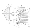
- 4 is a vertical sectional view of the lamp unit
- FIG. It is a perspective view which looks at a heat sink from front diagonally upper direction. It is a front view which shows a board
- FIG. 3 is an exploded perspective view of the lamp unit as seen obliquely from the front and above
- FIG. 4 is an exploded perspective view of the lamp unit as viewed obliquely from below
- 4 is a vertical sectional view of the lamp unit
- FIG. It is a perspective view which looks at a heat sink from front diagonally upper direction. It is a front view which shows a board
- FIG. 1 is a diagram schematic
- FIG. 4 is a front view of the state where the reflector unit is attached to the heat sink, viewed from the front side; 8 is an enlarged view of a portion including a light distribution forming portion in FIG. 7; FIG. 5 is an enlarged view of a portion including a light distribution forming portion in FIG. 4; FIG. It is a back view of a heat sink.
- FIG. 5 is an enlarged view of part of FIG. 4 schematically showing an example of optical paths of light emitted from a first light source and light emitted from a second light source; It is a figure which shows the light distribution pattern of the low beam in 1st Embodiment. It is a figure which shows the light distribution pattern of the high beam in 1st Embodiment.
- FIG. 8 is a diagram similar to FIG. 7 showing a state in which a reflector unit is attached to a heat sink in a first modified example as a first mode
- FIG. 5 is a diagram similar to FIG. 4 showing a lamp unit in a first modified example
- FIG. 12 is a diagram similar to FIG. 11 showing an example of optical paths of light emitted from a first light source and light emitted from a second light source in a second modified example as a second mode
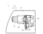
- FIG. 6 is a schematic diagram showing a vehicle headlamp according to a second embodiment as a third aspect of the present invention
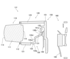
- FIG. 18 is an exploded perspective view of the lamp unit of FIG. 17
- FIG. 11 is an enlarged view of a reflector unit in the second embodiment
- FIG. 10 is a perspective view of the lamp unit in the second embodiment with the projection lens removed;
- FIG. 8 is a vertical cross-sectional view of a lamp unit according to a second embodiment;
- FIG. 11 is a perspective view of the lamp unit in the second embodiment with the projection lens, the lens holder, and the reflector unit removed;
- FIG. 11 is a schematic diagram showing a vehicle headlamp according to a third embodiment as a fourth aspect of the present invention;
- FIG. 24 is an exploded perspective view of the lamp unit of FIG. 23; It is a front view of the board
- FIG. 11 is a vertical cross-sectional view of a lamp unit according to a third embodiment; It is a figure which shows the modification of a board
- FIG. 1 is a diagram schematically showing a lamp in this embodiment, and is a diagram schematically showing a cross section of the lamp in the vertical direction.
- the lamp of this embodiment is a vehicle headlamp for an automobile.
- Vehicle headlamps are generally provided in front of a vehicle in left and right directions.
- "right” means the right side in the forward direction of the vehicle
- "left” means the left side in the forward direction of the vehicle.
- Each of the left and right vehicle headlamps has the same configuration, except that the shape is generally symmetrical in the left-right direction. Therefore, one vehicle headlamp will be described below.
- the vehicle headlamp 1 of this embodiment mainly includes a housing 10 and a lamp unit LU. 1 is a side view of the vehicle headlamp 1, and FIG. 1 shows a cross section of the housing 10 for easy understanding.
- the housing 10 has a lamp housing 11 and a front cover 12 having optical transparency.
- the front of the lamp housing 11 is open, and a front cover 12 is fixed to the lamp housing 11 so as to close the opening.
- a space formed by the lamp housing 11 and the front cover 12 is a lamp chamber R, and the lamp unit LU is accommodated in the lamp chamber R.
- FIG. 2 is an exploded perspective view of the lamp unit LU seen obliquely from the front and above.
- FIG. 3 is an exploded perspective view of the lighting unit LU as seen obliquely from below.
- FIG. 4 is a vertical sectional view of the lamp unit LU.
- the lighting unit LU of this embodiment includes a heat sink 20, a fan 30 that is an axial fan, a substrate 40, a reflector unit 50, a projection lens 60, a holder 70, is provided as the main configuration.
- 4 is a vertical cross-sectional view of the lamp unit LU along the optical axis of the projection lens 60, which will be described later, and the illustration of the fan 30 is omitted in FIG.
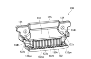
- FIG. 5 is a perspective view of the heat sink 20 viewed obliquely from the front and above.
- the heat sink 20 is made of a material with excellent heat dissipation, such as metal.
- the heat sink 20 of this embodiment includes a base plate 21 on which a substrate 40 is arranged, a plurality of radiation fins 22, a plurality of mounting bosses 23a and 23b, and a peripheral wall portion 24. Provided as a main component.
- the base plate 21 is a plate-like member having a front surface located on the front side and a back surface located on the rear side, and has an inclined portion 25 that is inclined rearwardly upward.
- the inclined portion 25 is provided with a pedestal 25a projecting forward, and an end surface 25s of the pedestal 25a is a flat surface that is upwardly inclined rearward.
- a substrate 40 is arranged on the end face 25s.
- Protrusions 26 protruding forward are provided on both left and right sides of the base 25a.
- Pins 27 projecting forward are provided on the right and left sides of the base plate 21 relative to the pedestal 25a.
- the plurality of heat radiation fins 22, mounting bosses 23a and 23b, and peripheral wall portion 24 are arranged on the back surface of the base plate 21 opposite to the substrate 40 side, extend rearward, and are integrally formed with the base plate 21. .
- the fan 30 is arranged behind the plurality of radiating fins 22 and fixed to the mounting bosses 23a and 23b. The air blown by the fan 30 cools the heat sink 20 .
- the rear side of the heat sink 20 on which the plurality of radiation fins 22, mounting bosses 23a and 23b, the peripheral wall portion 24, and the fan 30 are arranged will be described later.
- the substrate 40 is a plate-like member made of metal, for example, and is arranged on the end face 25s of the base 25a of the heat sink 20, as described above.
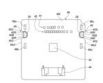
- FIG. 6 is a front view schematically showing the substrate 40.
- the outer shape of the substrate 40 is generally a symmetrical rectangular shape, and the substrate 40 has a pair of concave portions 45 in which left and right side surfaces 40sf facing each other are respectively recessed.
- the concave portion 45 has a substantially rectangular shape, and the side surfaces 40sf of the substrate 40 defining the concave portion 45 include a pair of straight portions 45S extending in the left-right direction and facing each other, and a tip in the direction of the depression extending in the vertical direction.
- the protrusions 26 of the heat sink 20 are inserted into the respective recesses 45 .
- the projection part 26 is shown by FIG.
- the vertical movement of the substrate 40 along the end surface 25 s is restricted by the pair of linear portions 45 S of the recess 45 and the outer peripheral surface of the protrusion 26 .
- the bottom 45B of one recess 45 and the outer peripheral surface of one protrusion 26, and the bottom 45B of the other recess 45 and the outer peripheral surface of the other protrusion 26 allow the substrate 40 to extend in the horizontal direction along the end face 25s. movement is restricted.
- the movement of the substrate 40 along the end surface 25 s is restricted by the concave portion 45 and the protrusion 26 , and the substrate 40 is positioned with respect to the heat sink 20 .
- the shape of the recess 45 is not particularly limited.
- the protrusion 26 may be press-fitted into the recess 45 .
- a first light source 41, a second light source 42, an integrated circuit 43, and a connector 44 are mounted on the front surface 40f of the substrate 40.
- the first light source 41 emits light forming a low-beam light distribution pattern from a planar emission surface.
- the second light source 42 emits light that forms a high beam light distribution pattern together with the light emitted from the first light source 41 from a planar emission surface.
- the first light source 41 and the second light source 42 are LED arrays composed of a plurality of LEDs (Light Emitting Diodes) arranged in the horizontal direction, and are arranged inside the bottom portion 45B of the concave portion 45 .
- the second light source 42 is positioned below the first light source and overlaps the recess 45 in the left-right direction, which is the direction in which the plurality of LEDs are arranged.
- the integrated circuit 43 is arranged below the second light source 42 and the connector 44 is arranged below the integrated circuit 43 .
- a circuit (not shown) is provided on the substrate 40, and the circuit connects the connector 44 and the first light source 41, the connector 44 and the integrated circuit 43, and the integrated circuit 43 and the second light source 42, respectively.
- Power is supplied to the connector 44 from a power supply unit (not shown). Therefore, power is supplied from the connector 44 to the first light source 41 , and power is supplied from the connector 44 to the second light source 42 via the integrated circuit 43 .
- the integrated circuit 43 includes a plurality of switch elements to individually adjust the power supplied to each LED of the second light source 42 .
- the integrated circuit 43 is not particularly limited as long as it can adjust the power supplied to at least one of the first light source 41 and the second light source 42 . Also, the arrangement of the integrated circuit 43 and the connector 44 is not particularly limited. Also, the integrated circuit 43 may not be mounted on the substrate 40, in which case the connector 44 and the second light source 42 are connected by a circuit.
- the portion of the substrate 40 where the first light source 41, the second light source 42, and the integrated circuit 43 are mounted overlaps the end surface 25s.
- the substrate 40 is also tilted, and the front surface 40f is tilted forward and upward.
- a normal 41L to the exit surface of the first light source 41 and a normal 42L to the exit surface of the second light source 42 are substantially perpendicular to the front surface 40f of the substrate 40 . Therefore, the perpendicular 41L and the perpendicular 42L face obliquely forward and upward.
- a perpendicular line 41L and a perpendicular line 42L shown in FIG. 4 are the same as a straight line that passes through the center of the emission surface, is parallel to the emission direction of the light with the highest intensity among the light emitted from the light source, and passes through the portion of the emission surface from which the light is emitted. is.
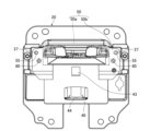
- FIG. 7 is a front view of the state in which the reflector unit 50 is attached to the heat sink 20, viewed from the front side, along the optical axis of the projection lens 60, which will be described later.
- the reflector unit 50 is arranged in front of the substrate 40 and the substrate 40 is sandwiched between the reflector unit 50 and the heat sink 20 .
- the reflector unit 50 of this embodiment includes a light distribution forming portion 50a and a cover portion 50b connected to the left and right sides and the lower side of the light distribution forming portion 50a. It is formed.
- the light distribution forming portion 50a is surrounded by a dashed line.
- the reflector unit 50 is fixed to the heat sink 20 by fixing the cover portion 50 b to the heat sink 20 with screws 80 .
- the material forming the reflector unit 50 include plated metal, and the reflector unit 50 is formed by, for example, cutting and plating a metal member obtained by casting.
- the light distribution forming portion 50a of this embodiment includes a first reflector 51, a pair of second reflectors 52a and 52b, a pair of upper side reflectors 53a and 53b, and a pair of lower side reflectors 53a and 53b. It has reflectors 54a and 54b as a main configuration.
- the first reflector 51 is arranged between the first light source 41 and the second light source 42 and extends in the front-rear direction.
- the first reflector 51 has a tapered shape toward a front end 51e, and upper and lower surfaces of the first reflector 51 are reflecting surfaces 51ur and 51dr that reflect light.
- the upper reflecting surface 51ur which is the upper surface
- the lower reflective surface 51dr which is the lower surface, is positioned above the normal line 42L of the second light source 42 and curves concavely upward.
- the front end 51e of the first reflector 51 has a shape that matches the cutoff line of a low beam light distribution pattern, which will be described later, and is gradually recessed rearward from the left and right ends toward the center.
- the vertical line 41L of the first light source 41 and the vertical line 42L of the second light source 42 are directed obliquely forward and upward. 1 approach the reflector 51;
- One second reflector 52a is arranged above the first reflector 51 and has a reflecting surface 52ar on the first reflector 51 side.
- the second reflector 52a of this embodiment is a plate-like member, and the side surface of the plate-like member is the reflecting surface 52ar.
- the reflecting surface 52ar and the reflecting surface 51ur on the upper side of the first reflector 51 extend along the parallel direction of the plurality of LEDs that constitute the first light source 41, and are arranged so as to sandwich the plurality of LEDs from above and below. A pair of reflectors.
- the other second reflector 52b is arranged below the first reflector 51 and has a reflecting surface 52br on the first reflector 51 side.
- the second reflector 52b of this embodiment is a plate-like member, and one main surface of the plate-like member is the reflecting surface 52br.
- the reflecting surface 52br and the reflecting surface 51dr on the lower side of the first reflector 51 extend along the parallel direction of the plurality of LEDs constituting the second light source 42, and are arranged so as to sandwich the plurality of LEDs from above and below. a pair of reflectors that
- One upper side reflector 53a is positioned in the space sandwiched between the upper reflecting surface 51ur of the first reflector 51 and the reflecting surface 52ar of the second reflector 52a. formed at one end of the The other upper side reflector 53b is formed at the other end of the space.
- the pair of upper side reflectors 53a and 53b are formed such that the distance between them increases from the rear toward the front.
- An opening 55 surrounded by the pair of upper side reflectors 53a and 53b, the first reflector 51, and the second reflector 52a is formed in the light distribution forming portion 50a, and the emission surface 41s of the first light source 41 is Overlaps the opening 55 .
- reference numerals are given to one first light source 41 and the emission surface 41s, and the reference numerals for the others are omitted.
- One of the lower side reflectors 54a is located in the space sandwiched between the lower reflecting surface 51dr of the first reflector 51 and the reflecting surface 52br of the second reflector 52b. It is formed at one end in the parallel direction.
- the other lower side reflector 54b is formed at the other end of the space.
- the pair of lower side reflectors 54a and 54b are formed such that the distance between them increases from the rear toward the front.
- An opening 56 surrounded by the pair of lower side reflectors 54a and 54b, the first reflector 51, and the second reflector 52b is formed in the light distribution forming portion 50a, and the emission surface 42s of the second light source 42 is overlaps with the opening 56 at .
- the opening 56 and the opening 55 penetrate from a flat facing surface 50as of the light distribution forming portion 50a facing substantially parallel to the substrate 40 to the surface opposite to the substrate 40 side. Note that the facing surface 50as may not be flat.
- Through-holes 57 are provided on both left and right sides of the cover portion 50b of the present embodiment, and the pins 27 of the heat sink 20 are inserted into the through-holes 57 . Therefore, the reflector unit 50 can be positioned with respect to the heat sink 20 by the peripheral surface defining the through hole 57 and the pin 27 .
- the integrated circuit 43 and the connector 44 overlap the cover portion 50b in the direction perpendicular to the front surface 40f of the substrate 40. As shown in FIG. Therefore, when the substrate 40 is viewed from above, the cover portion 50 b covers the integrated circuit 43 and the connector 44 mounted on the substrate 40 . Further, as shown in FIG.
- the light distribution forming portion 50a and the cover portion 50b are provided with a plurality of ribs 58 projecting rearward.
- the tip of the rib 58 contacts the front surface 40 f of the substrate 40 , and the substrate 40 is pressed against the heat sink 20 by the reflector unit 50 and fixed to the heat sink 20 .
- portions 46a, 46b, 46c, and 46d where the reflector unit 50 presses the substrate 40 are indicated by diagonal hatching.
- the reflector unit 50 presses four portions 46a, 46b, 46c and 46d, the portions 46a and 46b being positioned outside the bottom portion 45B of one of the recessed portions 45, and the portions 46c and 46d pressing the other. is located outside the bottom portion 45B of the recessed portion 45 of the . Therefore, the reflector unit 50 presses the portion of the substrate 40 outside the bottom portion 45B of each concave portion 45 .
- the parts 46a and 46b are positioned above and below one recess 45 as a reference, and sandwich this one recess 45 in the direction along the side surface 40sf.
- the parts 46c and 46d are located above and below the other recess 45, and sandwich the other recess 45 in the direction along the side surface 40sf. Therefore, the reflector unit 50 presses both sides of each recess 45 in the substrate 40 . Also, the external shapes of the parts 46a, 46b, 46c, and 46d are substantially rectangular, but are not particularly limited.
- the projection lens 60 is a lens that changes the divergence angle of transmitted light, and is arranged in front of the reflector unit 50 .
- the projection lens 60 is a biconvex aspherical lens having an outer shape elongated in the left-right direction and having a substantially oval track shape.
- a flange portion 61 is provided that extends along the length thereof.
- An optical axis 60 c of the projection lens 60 extends in the front-rear direction, intersects the first reflector 51 , and passes between the first light source 41 and the second light source 42 .
- the rear focal point 60f of the projection lens 60 is located near the front end 51e between the front end 51e of the first reflector 51 and the projection lens 60. is 10 mm or less. Note that the focal point 60f may be positioned at the front end 51e or may overlap the first reflector 51.
- FIG. Examples of the material forming the projection lens 60 include resin, glass, and the like.
- the holder 70 of this embodiment includes a cylindrical support portion 71 extending in the front-rear direction and a pair of legs extending rearward from the left and right sides of the rear end of the support portion 71. 72.
- a plurality of pedestals 73 projecting forward are provided at the front end of the support portion 71, and the flange portion 61 of the projection lens 60 is fixed to the pedestals 73 by, for example, ultrasonic welding or laser welding.
- the legs 72 are fixed to the heat sink 20 by screws 81 and the projection lens 60 is fixed to the heat sink 20 via the holder 70 .
- a resin such as opaque polycarbonate can be used.
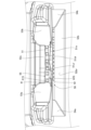
- FIG. 10 is a back view of the heat sink 20.
- FIG. A plurality of radiation fins 22 of the heat sink 20 are arranged in parallel with a space therebetween and extend in the left-right direction. In each figure, for ease of viewing, only one of each of the radiating fins 22 and the gaps 500 between the mutually adjacent radiating fins 22 is labeled.
- the uppermost radiating fin is designated as radiating fin 22a
- the lowest radiating fin is designated as radiating fin 22b.
- the radiation fins 22 refer to the radiation fins 22a, 22b and the radiation fins positioned between the radiation fins 22a, 22b and extending in the horizontal direction.
- the left and right sides of the heat radiation fins 22 and the upper side of the heat radiation fins 22a are surrounded by the peripheral wall portion 24.
- the peripheral wall portion 24 is a frame surrounding the radiation fins 22 as described above and is separated from the radiation fins 22 .
- the left and right walls of the peripheral wall portion 24 are shorter than the radiating fins 22 and the upper wall is longer than the radiating fins 22 in the front-rear direction.
- a fan 30 is provided behind the plurality of heat radiation fins 22.
- the fan 30 mainly includes an impeller 31 provided on the side opposite to the base plate 21 with respect to the plurality of radiation fins 22 and a support unit 33 .
- illustration of the impeller 31 is omitted in FIGS. 2 and 3 .
- FIG. 10 is also a view of the impeller 31 viewed along the rotation axis R1.
- Each of the impeller 31 and the support unit 33 is made of resin, for example.
- the impeller 31 rotates around a rotation axis R1 along a direction perpendicular to the back surface of the base plate 21. Also, the impeller 31 rotates along the back surface of the base plate 21 to send air to the gaps 500 between the adjacent radiation fins 22 .
- the impeller 31 of this embodiment rotates counterclockwise.
- the impeller 31 is rotatably supported by the support unit 33 .
- the support unit 33 mainly includes a base member 33a on which the impeller 31 is arranged, and a support member 33b provided on the side of the impeller 31 and the base member 33a when the fan 30 is viewed from the rear.
- the base member 33 a is a circular plate-like member and is arranged in front of the impeller 31 .
- the base member 33a is connected to the support member 33b via spokes 33c that are connected to the outer peripheral surface of the base member 33a and the inner peripheral surface of the support member 33b. Therefore, the support member 33b rotatably supports the impeller 31 via the base member 33a and the spokes 33c.
- illustration of the spokes 33c is omitted in FIG.
- the support member 33b is an outer frame that encloses the sides of the impeller 31 and the base member 33a, and is formed in a substantially square shape. In the support member 33b of the present embodiment, two substantially parallel sides of the substantially square support member 33b extend in the left-right direction.
- the support member 33b is shorter than the heat radiating fins 22 in the horizontal direction and longer than the space between the heat radiating fins 22a and 22b in the vertical direction.
- the front surfaces of the base member 33a and the support member 33b are in contact with the rear ends of the radiation fins 22, but may be separated from the rear ends.
- the four corners of the support member 33b are rounded.
- Through holes 33d are provided in the upper right and lower left corners of the four corners of the support member 33b, screws 501 are inserted into the through holes 33d, and the screws 501 are screwed into the mounting bosses 23a and 23b. Thereby, the fan 30 is attached to the heat sink 20 via the support member 33b and the attachment bosses 23a and 23b.
- FIG. 10 the mounting bosses 23a and 23b are hidden by the fan 30 and cannot be seen, but are illustrated with broken lines for easy understanding.
- a straight line passing through the rotation axis R1 and extending in the extending direction of the radiation fins 22 is indicated as a first reference line 503a
- a straight line passing through the rotation axis R1 and extending in a direction orthogonal to the first reference line 503a is indicated as a first reference line 503a. It is shown as a second reference line 503b.
- Four areas are formed by the reference lines 503a and 503b, and areas 510a, 510b, 510c, and 510d are shown as upper right, upper left, lower left, and lower right areas with respect to the rotation axis R1.
- each region is shown slightly displaced from the reference lines 503a and 503b.
- the regions 510a and 510b and the regions 510c and 510d are regions adjacent to each other in the extending direction of the radiation fins 22. . Further, since the impeller 31 rotates counterclockwise, the region 510a in the regions 510a and 510b and the region 510c in the regions 510c and 510d are regions on the rear side of the impeller 31 in the rotation direction.
- the mounting bosses 23a are provided in the rear region 510a, and the mounting bosses 23b are provided in the rear region 510c.
- mounting bosses 23a, 23b are provided in respective rear regions 510a, 510c. At least part of the mounting boss 23a should be provided in the rear area 510a, and at least part of the mounting boss 23b should be provided in the rear area 510c.
- the support member 33b is attached to the attachment bosses 23a and 23b as described above. Therefore, when the fan 30 is viewed from the rear, the mounting bosses 23 a and 23 b are located on the sides of the impeller 31 . Further, since through holes 33d are provided in the upper right and lower left corners of the support member 33b, the mounting boss 23a overlaps the upper right corner and the mounting boss 23b overlaps the lower left corner.
- the mounting boss 23a is located between the first reference line 503a and the radiating fin 22a farthest upward from the first reference line 503a, specifically, the gap between the radiating fin 22a and the radiating fin 22 adjacent to the radiating fin 22a. Located at 500.
- the mounting boss 23b is located outside the heat radiating fin 22b on the side opposite to the gap 500 side.
- the mounting bosses 23a and 23b positioned as described above do not overlap each other along the extending direction of the radiation fins 22. As shown in FIG.
- the mounting boss 23a is connected to the heat radiating fin 22a and the heat radiating fin 22 adjacent to the heat radiating fin 22a, and the mounting boss 23b is connected to the heat radiating fin 22b.
- the mounting bosses 23 a and 23 b may be connected to at least one of the mutually adjacent radiation fins 22 forming the gap 500 or may be separated from the radiation fins 22 .
- the impellers in the regions 510a and 510b adjacent to each other in the extending direction of the radiating fin 22 31 is shown as a predetermined area 520a.
- some of the LEDs of the first light source 41 overlap the predetermined area 520a.
- At least one LED of the first light source 41 may overlap at least part of the predetermined area 520a.
- Most of the wind flowing through the gap 500 flows toward the end side of the gap 500 overlapping the above-described region 510b under the influence of the vortex of the airflow caused by the rotation of the impeller 31 .
- the predetermined area 520 a is cooled more easily than the area outside the predetermined area 520 a , and the heat generated by the first light source 41 overlapping the predetermined area 520 a is easily transferred to the radiation fins 22 .
- the predetermined area 520 a is used, but even if the first light source 41 overlaps the predetermined area 520 b as described above, the heat generated by the first light source 41 is easily transmitted to the heat dissipation fins 22 .
- the predetermined region 520b is defined between the first reference line 503a and the radiating fin 22b farthest downward from the first reference line 503a, and the impeller 31 between the regions 510c and 510d adjacent to each other in the extending direction of the radiating fin 22.
- the first light source 41 may overlap both of the predetermined regions 520a and 520b. Although the first light source 41 has been described above, the second light source 42 may overlap the predetermined areas 520a and 520b in the same manner as the first light source 41 does.
- the structure 600 includes a conductive member 601 that supplies power to the fan 30 , and the conductive member 601 includes power supply wiring 605 including a connector 603 .
- a fan-side connector 35 a of the fan-side wiring 35 extending from the fan 30 is connected to the connector 603 . Also, the connector 603 is fixed to the rear surface of the base plate 21 between the left wall of the peripheral wall portion 24 and the heat radiation fins 22 .
- a part of the power supply side wiring 605 is supported by a clamp 630 .
- Clamp 630 includes a holding portion 631 and a hook portion 633 .
- the holding portion 631 has a substantially concave shape when the fan 30 is viewed from the rear, and is connected to the hook portion 633 .
- the hooking portion 633 is hooked to the receiving member 22c by sandwiching the left and right surfaces of the receiving member 22c located in the region 510d.
- the receiving member 22 c is a plate-like member and is provided on the back surface of the base plate 21 .
- the receiving member 22c is connected to the surface of the radiation fin 22b on the side opposite to the gap 500 side.
- the receiving member 22c may dissipate heat as heat dissipating fins.
- the power-supply-side wiring 605 passes through the holding portion 631 in the front-rear direction and is hooked on the holding portion 631 , so that the holding portion 631 holds the power-supply-side wiring 605 .
- the power supply wiring 605 further extends rearward from the holding section 631 and is connected to a power supply section (not shown). When the power supply unit supplies power to the fan 30 via the power supply wiring 605 and the fan wiring 35, the fan 30 rotates.
- the structure 600 is located in areas 710c and 710d other than areas 710a and 710b on the leeward side of the wind passing through the gap 500 in the extending direction of the heat radiating fins 22 when the fan 30 is viewed from the rear.
- regions 710a, 710b, 710c, and 710d are shown slightly displaced from the other regions described above for ease of viewing. Regions 710a, 710b, 710c, and 710d are described below.
- a region 710a is a region on the left side of the gap 500 between the heat radiating fins 22 adjacent to each other and on the left side of the heat radiating fins 22 provided above the first reference line 503a in the region 510b.
- the region 710b of the present embodiment is a region on the right side of the gap 500 between the adjacent heat dissipating fins 22 provided below the first reference line 503a in the region 510d and on the right side of the heat dissipating fins 22 .
- Regions 710c and 710d are regions on the rear surface side of the base plate 21 outside the regions surrounded by the radiation fins 22a and 22b, excluding the regions 710a and 710b.
- the area 710c is an area provided above a straight line parallel to the first reference line 503a and passing through the heat radiation fins 22a and above the area 710b.
- the area 710d is an area provided below a straight line parallel to the first reference line 503a and passing through the radiation fins 22b and below the area 710a.
- FIG. 10 shows an example in which the conductive member 601 and the clamp 630 are arranged in the region 710d, and are not arranged in the regions 710a and 710b. be provided. Note that the conductive member 601 and the clamp 630 may be provided in the region 710c. The conductive member 601 and the clamp 630 are located at a position lower than the rear end of the radiation fin 22 in the front-rear direction. The conductive member 601 is arranged apart from the heat radiating fins 22 .
- the mounting bosses 23a and 23b are located on the sides of the impeller 31 in the regions 510a and 510c on the rear side of the impeller 31 in the rotational direction.
- the wind flows in the opposite direction to the mounting boss 23a. Therefore, the mounting boss 23a is provided outside the traveling path of the wind flowing through the gap 500, and is provided at a position where the wind is not blocked. It will be.
- blocking of the air by the mounting boss 23 a is suppressed, and the air flowing through the gap 500 where the mounting boss 23 a is positioned is blown out to the left side of the heat radiating fin 22 through the gap 500 .
- the wind flows in the opposite direction to the mounting bosses 23b. As a result, blocking of the wind by the mounting boss 23b is also suppressed.
- the air tends to be blown to the left side of the heat radiating fins 22 in the gaps 500 other than the gaps 500 where the mounting bosses 23a are located, in the gaps 500 above the first reference line 503a. Also, in the gap 500 below the first reference line 503a, the air tends to be blown out to the right side of the radiation fin 22. As shown in FIG.
- the conductive member 601 and the clamp 630 are located in a region 710d other than the regions 710a and 710b on the leeward side of the wind passing through the gap 500 in the extending direction of the heat radiating fins 22. Accordingly, the conductive member 601 and the clamp 630 are provided outside the traveling path of the wind passing through the gap 500, and are provided at a position where the wind is not blocked. As a result, the wind is blown out to the side of the radiation fins 22 while the blocking of the wind by these is suppressed.
- FIG. 11 is an enlarged view of part of FIG. 4 and schematically shows an example of optical paths of light emitted from the first light source 41 and light emitted from the second light source 42 . Note that the reflection angle, refraction angle, and the like of light shown in FIG. 11 may not be accurate.
- the first light source 41 When forming a low-beam light distribution pattern, light is emitted from the first light source 41 .
- Part of the light L1a emitted from the first light source 41 passes between the upper reflecting surface 51ur of the first reflector 51 and one of the second reflectors 52a and directly enters the projection lens 60 .
- Another part of the light L1b emitted from the first light source 41 is reflected toward the projection lens 60 at a portion including the front end of the upper reflecting surface 51ur of the first reflector 51, and enters the projection lens 60. do.
- Another part of the light L1c emitted from the first light source 41 is reflected by the reflecting surface 52ar of one of the second reflectors 52a, and the part including the front end of the upper reflecting surface 51ur of the first reflector 51 is reflected toward the projection lens 60 and enters the projection lens 60 .
- the front end 51e of the first reflector 51 has a shape that matches the cutoff line. A cutoff line is formed in the light distribution pattern. Also, although not illustrated, part of the light emitted from the first light source 41 that diffuses in the horizontal direction is reflected by the pair of upper side reflectors 53 a and 53 b and enters the projection lens 60 . .
- the light emitted from the first light source 41 and directly incident on the projection lens 60 and the light emitted from the first light source 41 and reflected by the reflector unit 50 and incident on the projection lens 60 form a low-beam light distribution.
- a pattern is formed.
- the light having this low-beam light distribution pattern is transmitted through the projection lens 60 and emitted from the vehicle headlamp 1 via the front cover 12 .
- the light distribution pattern of the low beam projected forward of the vehicle is a light distribution pattern that is inverted by the projection lens 60. be.
- the light L1a that directly enters the projection lens 60 is light emitted mainly in a direction parallel to the normal 41L.
- Light L1b reflected by the first reflector 51 and incident on the projection lens 60 and light L1c reflected by the second reflector 52a and reflected by the first reflector 51 and incident on the projection lens 60 are mainly different from the perpendicular line 41L. This is light emitted in parallel directions.
- the light L1a may include light emitted in a direction non-parallel to the normal 41L
- the light L1c may include light emitted in a direction parallel to the perpendicular 41L.
- FIG. 12 is a diagram showing a low beam light distribution pattern in this embodiment.
- S indicates a horizontal line
- V indicates a vertical line passing through the center of the vehicle in the left-right direction
- the low-beam light distribution pattern PL projected onto a virtual vertical screen placed 25 m in front of the vehicle is indicated by a thick line.
- the reflector unit 50 is shaped so that the light distribution pattern of the light from the first light source 41 incident on the projection lens 60 becomes such a low-beam light distribution pattern PL.
- the cutoff line CL of the low-beam light distribution pattern PL corresponds to the shape of the front end 51e of the first reflector 51, and has a step in this embodiment.
- the light from the first light source 41 forms the low-beam light distribution pattern PL
- the vehicle headlamp 1 emits light having the low-beam light distribution pattern PL.
- Part of the light L2a emitted from the second light source 42 directly enters the projection lens 60 through the space between the lower reflecting surface 51dr of the first reflector 51 and the other second reflector 52b.
- Another portion of the light L2b emitted from the second light source 42 is reflected toward the projection lens 60 at a portion including the front end portion of the lower reflecting surface 51dr of the first reflector 51, and is reflected toward the projection lens 60.
- FIG. 1 Another portion of the light L2c emitted from the second light source 42 is reflected toward the projection lens 60 by the reflecting surface 52br of the other second reflector 52b, and enters the projection lens 60.
- FIG. of the light emitted from the second light source 42 the light passing through the vicinity of the front end 51e of the first reflector 51 causes the light distribution pattern formed by the light emitted from the second light source 42 to have a cutoff line corresponding to the front end 51e. It is formed.
- part of the light emitted from the second light source 42 that diffuses in the horizontal direction is reflected by the pair of lower side reflectors 54a and 54b and enters the projection lens 60. do.
- This additional light distribution pattern is a light distribution pattern in which a high beam light distribution pattern is formed by being added to the low beam light distribution pattern PL. , and the light emitted from the first light source 41 to form a high beam light distribution pattern.
- an additional light distribution pattern is formed by the light from the second light source 42 , and the light having this additional light distribution pattern is transmitted through the projection lens 60 and emitted from the vehicle headlamp 1 through the front cover 12 . be done.
- the additional light distribution pattern projected forward of the vehicle is a light distribution pattern that is reversed by the projection lens 60, like the low beam light distribution pattern PL.
- the cutoff line of the additional light distribution pattern is defined by the front end 51e of the first reflector 51, similarly to the cutoff line CL of the low beam light distribution pattern PL. Therefore, the cutoff line of the additional light distribution pattern and the cutoff line CL of the light distribution pattern PL of the low beam approximately match, and the light distribution pattern of the high beam is a combination of the additional light distribution pattern and the light distribution pattern PL of the low beam. becomes.
- the upper side of the low-beam light distribution pattern PL and the lower side of the additional light distribution pattern overlap, but the low-beam light distribution pattern PL and the additional light distribution pattern do not have to overlap.
- at least part of the cutoff line of the additional light distribution pattern and at least part of the cutoff line CL of the low beam light distribution pattern PL match, and the additional light distribution pattern and the low beam light distribution pattern PL are connected.
- the light L2a that directly enters the projection lens 60 is light emitted mainly in a direction parallel to the normal 42L.
- Light L2b reflected by the first reflector 51 and incident on the projection lens 60 and light L2c reflected by the second reflector 52a and incident on the projection lens 60 are mainly emitted in a direction non-parallel to the perpendicular 42L.
- the light L2a may include light emitted in a direction non-parallel to the normal 42L
- the light L2b may include light emitted in a direction parallel to the perpendicular 42L.
- the additional light distribution pattern can be changed, and the light distribution pattern of the high beam can be changed. can be changed.
- FIG. 13 is a diagram showing the light distribution pattern of the high beam in this embodiment, and is a diagram showing the light distribution pattern of the high beam in the same manner as in FIG.
- the high beam light distribution pattern PH shown in FIG. 13 is for the case where light is emitted from all the LEDs that constitute the second light source 42 .
- the cutoff line CL in the low-beam light distribution pattern PL is indicated by a dotted line.
- a region below the cutoff line CL in the light distribution pattern PH of the high beam is formed mainly by the light from the first light source, and a region above the cutoff line CL is formed mainly by the light from the second light source 42 .
- the substrate 40 on which the first light source 41 and the second light source 42 are mounted has recesses 45 in which the side surfaces 40sf facing each other are respectively recessed. .
- the reflector unit 50 presses a portion of the substrate 40 outside the bottom portion 45B of each concave portion 45 . Therefore, the strength of the portion outside the bottom 45B of each recess 45 in the substrate 40 is weakened compared to the case where the substrate 40 does not have the recess 45, and the reflector unit 50 has such strength. Press the weakened area.
- the distortion of the substrate 40 due to the pressing force of the reflector unit 50 can be concentrated on the portion where the strength is weakened. , the strain inside the bottom portion 45B of the recess 45 can be reduced. Further, in the vehicle headlamp 1 of the present embodiment as the first aspect, the first light source 41 and the second light source 42 are positioned inside the bottom portion 45B of the recess 45 . Therefore, according to the vehicle headlamp 1 of the present embodiment as the first aspect, the orientations of the first light source 41 and the second light source 42 change due to the distortion of the substrate 40 compared to the above case. can be suppressed, and a light distribution pattern of low beam and high beam can be easily formed.
- the reflector unit 50 presses the concave portion 45 side on one side and the concave portion 45 side on the other side of the substrate 40 .
- the substrate 40 and the heat sink 20 are more likely to be separated from each other. It is possible to suppress the displacement of the relative position and facilitate formation of a light distribution pattern of low beam and high beam.
- the reflector unit 50 presses both sides of each recess 45 in the substrate 40 .
- the substrate 40 and the heat sink are more likely to be separated from each other. It is possible to suppress the displacement of the relative position with 20 .
- the reflector unit 50 has a flat facing surface 50as facing the substrate 40, and a surface from the facing surface 50as to the surface opposite to the substrate 40 side. It has openings 55 and 56 therethrough.
- the first light source 41 overlaps the aperture 55 and the aperture 56 overlaps the second light source 42 . Therefore, according to the vehicle headlamp 1 of the present embodiment as the first aspect, the facing surface 50as can be formed more easily by cutting than, for example, when the facing surface 50as is not flat.
- the integrated circuit 43 for adjusting the power supplied to at least one of the first light source 41 and the second light source 42 and the connector 44 are formed on the substrate 40. , and the integrated circuit 43 and the connector 44 are covered by the reflector unit 50 . Therefore, according to the vehicle headlamp 1 of the present embodiment as the first aspect, it is possible to suppress the irradiation of the integrated circuit 43 with sunlight or the like that enters from the outside through the projection lens 60 .
- the bright parts in the low beam light distribution pattern and the high beam light distribution pattern greatly affect visibility.
- the vicinity of the cutoff line in the light distribution pattern for low beams is bright, and the vicinity of the center of the light distribution pattern for high beams is bright.
- the light emission surfaces of the first light source and the second light source are planar, the first light source and the second light source are mounted on different substrates, and the first light source and the second light source are mounted on different substrates.
- a normal to the exit surface of each of the second light sources approaches the first reflector toward the front.
- the luminous flux of light emitted from a light source having a planar emission surface tends to increase as it approaches the perpendicular line of the emission surface.
- the light from the first light source can brighten the front end portion of the upper surface of the first reflector, and can brighten the vicinity of the cutoff line in the light distribution pattern of the low beam.
- the light from the second light source can brighten the front end portion of the lower surface of the first reflector, brighten the low-beam light distribution pattern side of the additional light distribution pattern, and brighten the vicinity of the center of the high-beam light distribution pattern.
- the first light source and the second light source are mounted on different substrates, so the number of parts tends to increase.
- the first light source 41 and the second light source 42 are mounted on the common substrate 40, so that the first light source 41 and the second light source 42 are The number of parts can be reduced as compared with the case where they are mounted on different substrates.
- the perpendicular 41L of the emission surface 41s of the first light source 41 is the same as that of the emission surfaces of the first light source and the second light source in the first patent document. Unlike the vertical line, it moves away from the first reflector 51 toward the front. Therefore, the luminous flux of the light L1b emitted from the first light source 41 and directly incident on the front end of one reflecting surface 51ur of the first reflector 51 tends to decrease, making it difficult to brighten the front end. However, the light L1c emitted from the first light source 41 and reflected by the second reflector 52a also enters the front end portion of the reflecting surface 51ur of the first reflector 51 together with the light L1b.
- the vehicle headlamp 1 of the present embodiment as the second aspect can suppress the front end portions of the upper and lower surfaces of the first reflector 51 from becoming dark.
- the vehicle headlamp 1 of the present embodiment it is possible to suppress the vicinity of the cutoff line CL in the light distribution pattern PL of the low beam and the vicinity of the center of the light distribution pattern PH of the high beam from becoming dark, thereby improving visibility. can suppress the decrease in
- the light L1c which is the part of the light emitted from the first light source 41, diverges at the divergence angle of the second reflector 52a. is made smaller than when is incident and reflected toward the first reflector 51 . Therefore, according to the vehicle headlamp 1 of the present embodiment as the second aspect, it is possible to further suppress darkening in the vicinity of the cutoff line CL in the light distribution pattern PL of the low beam.
- the reflecting surface 52ar of the second reflector 52a that reflects the light L1c is a part of the spheroid, and one focal point of the spheroid is at the front end of the reflecting surface 51ur of the first reflector 51.
- the other focal point is located at the intersection of the exit surface 41s of the first light source 41 and the vertical line 41L.
- the shape of the reflecting surface 52ar is not particularly limited. Another part of the light L1c may be reflected toward the first reflector 51 with a divergence angle that is the same as or greater than that when incident on one of the second reflectors 52a.
- the other part of the light L2c out of the light emitted from the second light source 42 is emitted from the other second reflector 52b. It is reflected towards projection lens 60 with a greater divergence angle than when incident. Therefore, according to the vehicle headlamp 1 of the present embodiment as the second aspect, the light distribution pattern PH of the high beam can be easily widened upward. Another part of the light L2c may be reflected toward the projection lens 60 with the same or smaller divergence angle than when incident on the other second reflector 52b.
- the vehicle headlamp 1 of the present embodiment as a second aspect includes an integrated circuit 43 mounted on the substrate 40 and adjusting power supplied to at least one of the first light source 41 and the second light source 42. Prepare more.
- the reflector unit 50 has a cover portion 50 b that covers the integrated circuit 43 . Therefore, according to the vehicle headlamp 1 of the present embodiment, it is possible to suppress the irradiation of the integrated circuit 43 with sunlight or the like that enters from the outside through the projection lens 60 .
- the first aspect of the present invention has been described using the first embodiment as an example, the first aspect of the present invention is not limited to this.
- the heat sink 20 having the protrusions 26 to be inserted into the respective recesses 45 was described as an example.
- the heat sink 20 may not have the protrusions 26 .
- the reflector unit 50 that presses both sides of each concave portion 45 in the substrate 40 has been described as an example.
- the reflector unit 50 may press the portion of the substrate 40 outside the bottom portion 45 ⁇ /b>B, which is the tip of each concave portion 45 in the concave direction.
- the reflector unit 50 may press one side of each recess 45 in the substrate 40, for example, may press only the portions 46a and 46c shown in FIG. 6, or may press only the portions 46b and 46d. good.
- the reflector unit 50 may further press the portion of the substrate 40 inside the recess 45 .
- the substrate 40 having the recesses 45 on each side was described as an example.
- the substrate 40 only needs to have recesses 45 in which side surfaces facing each other are recessed.
- one side and the other side of the substrate 40 may have a plurality of recesses 45 , and the number of recesses 45 on one side may differ from the number of recesses 45 on the other side.
- the substrate 40 on which the first light source 41 and the second light source, which are LED arrays, are mounted has been described as an example.
- the light source mounted on the substrate 40 is not particularly limited.
- the reflector unit 50 that covers the connector 44 mounted on the substrate 40 has been described as an example. However, as a first aspect, the reflector unit 50 does not have to cover the connector 44 as shown in FIG.
- FIG. 14 is a diagram similar to FIG. 7 showing a state in which the reflector unit 50 is attached to the heat sink 20 in the first modified example as the first mode, and FIG. 15 shows the lamp unit LU in the first modified example.
- FIG. 5 is a view similar to FIG. 4; Constituent elements that are the same as or equivalent to those of the above-described embodiment are denoted by the same reference numerals, and overlapping descriptions are omitted unless specifically described.
- the shape of the cover portion 50b is different from that of the first embodiment.
- the cover portion 50b of the reflector unit 50 of this modified example is not formed on the lower side of the connector 44 in the direction along the front surface 40f of the substrate 40, which is the side opposite to the first light source 41 and the second light source 42 side. Therefore, compared to the case where the reflector unit 50 is formed on the opposite side of the connector 44 from the first light source 41 and the second light source 42 side, it is possible to easily connect other connectors to the connector 44 .
- the cover portion 50b does not cover the connector 44 when the substrate 40 is viewed from above, it is possible to make it easier to connect another connector to the connector 44 .
- a flat facing surface 50as of the light distribution forming portion 50a that faces the front surface 40f of the substrate 40 in a substantially parallel manner extends to the outer edge of the surface of the reflector unit 50 on the substrate 40 side. Therefore, for example, the facing surface 50as can be easily formed by cutting.
- the vehicle headlamp 1 as the lamp has been described as an example.
- the lighting fixture as the first aspect includes a substrate on which a light source is mounted, a heat sink on which the substrate is arranged, and a reflector that presses the substrate against the heat sink and reflects part of the light emitted from the light source. All you have to do is
- the lamp as the first aspect may not be for vehicles, and may emit light that forms a predetermined image.
- the second aspect of the present invention has been described with the first embodiment as an example, but the second aspect of the present invention is not limited to this.
- the first light source 41 in which the perpendicular 41L moves forward and away from the first reflector 51, and the second light source in which the perpendicular 42L approaches the first reflector 51 forward have been described as examples.
- the normal to one light source of the first light source 41 and the second light source 42 moves forward away from the first reflector 51, and the normal to the other light source moves forward from the first reflector 51.
- the vertical line 41L of the first light source 41 may move forward toward the first reflector 51
- the vertical line 42L of the second light source 42 may move forward and away from the first reflector 51.
- the first light source 41 and the second light source which are LED arrays, have been described as an example.
- the emission surfaces of the first light source 41 and the second light source are not particularly limited as long as they have flat plate-like emission surfaces.
- FIG. 16 is a diagram showing an optical path example of light emitted from the first light source 41 and light emitted from the second light source 42 in the second modified example as the second mode, similarly to FIG. Note that the reflection angle, refraction angle, etc. of light shown in FIG. 16 may not be accurate.
- the same or equivalent components as those of the first embodiment are denoted by the same reference numerals, and overlapping descriptions will be omitted unless specifically described.
- the substrate 40 is tilted upward and forward, and the light distribution forming portion 50a of the reflector unit 50 is vertically different from the light distribution forming portion 50a of the above-described embodiment. It is assumed that the shape is reversed to .
- part of the light L1a emitted from the first light source 41 passes between the upper reflecting surface 51ur of the first reflector 51 and one of the second reflectors 52a, and passes directly to the projection lens 60.
- the other portion of the light L1b is reflected toward the projection lens 60 at a portion including the front end portion of the upper reflecting surface 51ur of the first reflector 51 and enters the projection lens 60 .
- Another part of the light L1c is reflected toward the projection lens 60 by the reflecting surface 52ar of the second reflector 52a and enters the projection lens 60.
- part of the light emitted from the second light source 42 and diffused in the horizontal direction is reflected by the pair of lower side reflectors 54a and 54b in the same manner as in the above embodiment. and enters the projection lens 60 .
- the light emitted from the first light source 41 and directly incident on the projection lens 60 and the light emitted from the first light source 41 and reflected by the reflector unit 50 and incident on the projection lens 60 are combined as shown in FIG.
- a low-beam light distribution pattern PL shown is formed.
- the vertical line 41L of the first light source 41 approaches the first reflector 51 toward the front. can. Therefore, according to the vehicle headlamp 1 of the present modification as the second aspect, it is possible to suppress the vicinity of the cutoff line CL from becoming dark in the light distribution pattern PL of the low beam, thereby suppressing deterioration in visibility. can.
- Part of the light L2a emitted from the second light source 42 passes between the lower reflecting surface 51dr of the first reflector 51 and the second reflector 52b and directly enters the projection lens 60.
- the other portion of the light L2b is reflected toward the projection lens 60 at a portion including the front end portion of the lower reflecting surface 51dr of the first reflector 51 and enters the projection lens 60 .
- Another portion of the light L2c is reflected by the reflecting surface 52br of the second reflector 52b and is reflected toward the projection lens 60 at a portion including the front end portion of the reflecting surface 51dr of the first reflector 51 .
- part of the light emitted from the second light source 42 that is diffused in the left-right direction is partly reflected by the pair of lower side reflectors 54a and 54b, as in the first embodiment. It is reflected and enters the projection lens 60 .
- This additional light distribution pattern is a light distribution pattern in which a high beam light distribution pattern is formed by being added to the low beam light distribution pattern PH.
- a high beam light distribution pattern PH shown in is formed.
- the luminous flux of the light L2b emitted from the second light source 42 and directly incident on the front end of the reflecting surface 51dr of the first reflector 51 tends to decrease, making it difficult to brighten the front end.
- the light L2c emitted from the second light source 42 and reflected by the second reflector 52b also enters the front end portion of the reflecting surface 51dr of the first reflector 51 together with the light L2b. Reflected towards 60 . Therefore, even with such a second light source 42, it is possible to prevent the front end portion of the reflecting surface 51dr, which is the lower surface of the first reflector 51, from becoming dark. Therefore, according to the vehicle headlamp 1 of the present modification as the second aspect, it is possible to suppress the vicinity of the center of the light distribution pattern PH of the high beam from becoming dark, thereby suppressing deterioration of visibility.
- the vehicle headlamp 1 of this modified example as the second mode can reduce the number of parts while suppressing deterioration of visibility, as in the first embodiment.
- the light L1c which is part of the light emitted from the first light source 41, is directed toward the projection lens 60 with a larger divergence angle than when incident on the second reflector 52a. reflected by Therefore, according to the vehicle headlamp 1 of the present modified example as the second mode, the light distribution pattern PL of the low beam can be easily widened downward. Another part of the light L1c may be reflected toward the projection lens 60 with the same or smaller divergence angle than when incident on the second reflector 52a.
- the light L2c which is part of the light emitted from the second light source 42, has a smaller divergence angle than when incident on the second reflector 52b, and reaches the first reflector 51. reflected towards. Therefore, according to the vehicle headlamp 1 of the present modified example as the second aspect, it is possible to further suppress the darkening of the vicinity of the center of the light distribution pattern PH of the high beam.
- the reflecting surface 52br of the second reflector 52b that reflects the light L2c is a part of the spheroid, and one focal point of the spheroid is at the front end of the reflecting surface 51dr of the first reflector 51.
- the other focus is located at the center of the exit surface 42 s of the second light source 42 .
- the shape of the reflecting surface 52br is not particularly limited. Another part of the light L2c may be reflected toward the first reflector 51 with a divergence angle that is the same as or greater than when incident on the second reflector 52b.
- the reflector unit 50 having the cover portion 50b covering the integrated circuit 43 and the connector 44 has been described as an example.
- the cover portion 50b may not cover at least one of the integrated circuit 43 and the connector 44, and the reflector unit 50 may not have the cover portion 50b.
- the substrate 40 having the concave portion 45 into which the protrusion 26 of the heat sink 20 is inserted has been described as an example.
- the substrate 40 may not have the recess 45 .
- the reflector unit 50 that presses the substrate 40 against the heat sink 20 has been described as an example.
- the reflector unit 50 may not press the substrate 40 against the heat sink 20, in which case the substrate 40 is fixed to the heat sink 20 by screws, for example.
- FIG. 17 is a schematic diagram of a vehicle headlamp according to this embodiment. As shown in FIG. 17, in the vehicle headlamp 1 of the present embodiment, the configuration of the lighting unit LU is different from that of the lighting unit LU of the first embodiment.
- FIG. 18 is an exploded perspective view of the lamp unit LU shown in FIG.
- the lighting unit LU includes a projection lens 110, a lens holder 120, a reflector unit 130, a substrate 140, a heat sink 150, and a cooling fan 160.
- the projection lens 110 of this embodiment has a lens main body portion 111 and a flange-like fixing portion 112 provided on the outer periphery of the lens main body portion 111 .
- the lens body 111 has a light exit surface 113 that is convex and an incident surface 114 that has a smaller curvature than the light exit surface 113 .
- the lens main body 111 has a shape in which the upper and lower portions of a circular lens when viewed from the front are cut in a plane shape, and is thin in the vertical direction. It should be noted that the focal plane of the projection lens 110 is generally aligned with the light exit plane of the light emitting element, which will be described later.
- the lens holder 120 has a substantially square tubular shape that matches the outer shape of the lens main body 111, and includes a bottom plate 121, side plates 122 connected to both lateral edges of the bottom plate 121, and It has a top plate portion 123 facing the bottom plate portion 121 and connected to each of the side plate portions 122 .
- the bottom plate portion 121 and the top plate portion 123 extend substantially horizontally, and the side plate portion 122 extends substantially vertically.
- FIG. 19 is a diagram showing the reflector unit 130 in this embodiment.
- the reflector unit 130 is made of metal, and as shown in FIGS. 18 and 19, has a reflecting portion 131, a light shielding cover 132, a fixing portion 134, and a blind plate 135 as main components. Further, the reflector unit 130 is formed with an opening 130h through which an emission surface of a light emitting element, which will be described later, is exposed from behind.
- the opening 130h has a horizontally long, generally rectangular shape.
- the reflecting portion 131 is a substantially trapezoidal portion extending forward and downward from directly below the opening 130h, and the upper base of the reflecting portion 131 forms the lower edge of the opening 130h. The length of the upper base and the width of the opening 130h in the horizontal direction are approximately equal.
- the reflecting portion 131 reflects, toward the projection lens 110, the light emitted forward and downward from the light source exposed through the opening 130h.
- a light shielding cover 132 is provided below the reflecting portion 131 .
- the light shielding cover 132 has a light scattering portion 132d, a plate-like cover portion 132p, and a side cover portion 132s, and shields the light shielding cover 132 from the sunlight incident from the projection lens 110 on the side opposite to the projection lens 110 side.
- a light scattering portion 132 d extends vertically downward from the lower end of the reflecting portion 131 .
- the surface of the light scattering portion 132d has a shape in which a plurality of semi-cylindrical columns extending in the vertical direction are arranged in parallel in the horizontal direction. Therefore, the light reflected by the light scattering portion 132d is scattered.
- the width of the light scattering portion 132 d in the horizontal direction is narrower than the width of the lower base of the trapezoidal reflecting portion 131 and substantially the same as the width of the upper base of the reflecting portion 131 .
- a plate-like cover portion 132p is connected to the lower edge of the light scattering portion 132d.
- the plate-shaped cover portion 132p extends forward and horizontally from the light scattering portion 132d.
- the upper surface of the plate-shaped cover portion 132p has a shape in which a plurality of semi-cylindrical columns extending in the front-rear direction are arranged side by side in the left-right direction. Therefore, the light reflected by the upper surface of the plate-like cover portion 132p is scattered.
- the lateral width of the plate-shaped cover portion 132p is smaller than the lateral width of the bottom plate portion 121 of the lens holder 120 and slightly smaller than the width of the recess 121c.
- each end portion 132pe in the left-right direction of the plate-like cover portion 132p extends to the rear of the light scattering portion 132d.
- a side cover portion 132s is connected to the rear end of each end portion 132pe.
- Each of the side cover portions 132s is a plate-like member that extends from a connection portion with the end portion 132pe so as to draw a convex arc toward the upper rear side.
- the upper surface of each side cover portion 132s is generally flat and does not particularly have light scattering properties.
- a flat fixing portion 134 extending in the vertical direction is connected to the rear end of each side cover portion 132s.
- Each fixing part 134 is connected to the left and right edges of the opening 130h.
- Each fixing portion 134 is formed with a screw hole 134h.
- the upper edge of the opening 130h is connected to a substantially rectangular plate-like blind plate 135. As shown in FIG. Left and right edges of blind plate 135 are connected to fixing portions 134 respectively.
- the substrate 140 has components mounted on one surface and arranged along the vertical direction.
- the substrate 140 has a substantially rectangular shape, and screw holes 140h are formed near the upper left and right corners.
- Each screw hole 140h is formed at a position overlapping with the screw hole 134h of the reflector unit 130. As shown in FIG. Therefore, a common screw is inserted through the screw hole 134h and the screw hole 140h.
- a plurality of terminals 145 are provided on the lower side of the substrate 140 to which a connector is connected.
- a cable is connected to the connector.
- a light source 141 is mounted on one surface of the substrate 140 .
- the light source 141 includes a plurality of light emitting elements 141e that are arranged side by side and emit light forward. An LED is mentioned as such a light emitting element.
- the plurality of light emitting elements 141e are mounted in a row in the horizontal direction on the upper side of the substrate 140 .
- the reflector unit 130 and the substrate 140 are arranged on the heat sink 150, the light emitting surfaces of the plurality of light emitting elements 141e, which are the light emitting surfaces of the light source 141, are exposed from the openings 130h of the reflector unit 130.
- the light source 141 is sandwiched from the left and right by the pair of screw holes 140h. Electronic components other than the light source 141 are also mounted on the substrate 140 .
- the heat sink 150 includes a base plate 151 on which the substrate 140 is arranged, and a plurality of cooling fins 152 arranged in parallel on the side of the base plate 151 opposite to the substrate 140 side.
- the base plate 151 is formed with screw holes 150 h at positions corresponding to the screw holes 134 h of the reflector unit 130 and the screw holes 140 h of the substrate 140 . Accordingly, the screws fixed to the screw holes 150h are inserted through the screw holes 134h and 140h.
- thermally conductive grease is preferably interposed between the base plate 151 and the substrate 140 .
- FIG. 20 is a diagram in which the projection lens 110 is removed from the lamp unit LU in this embodiment.
- the reflector unit 130 is fixed to the heat sink 150 together with the substrate 140 as shown in FIG.
- the lens holder 120 is fixed to the heat sink 150 by screwing the fixing portion 125 of the lens holder 120 to the heat sink 150 .
- a portion of the plate-like cover portion 132p of the reflector unit 130 enters the concave portion 121c formed in the bottom plate portion 121 of the lens holder 120.
- FIG. Since a part of the plate-like cover portion 132p enters the concave portion 121c in this way, it is possible to suppress positional deviation between the reflector unit 130 and the lens holder 120 in the left-right direction.
- FIG. 21 is a vertical sectional view of the lamp unit LU in this embodiment. Note that FIG. 21 is a sectional view passing between the cooling fins 152, so the cooling fins 152 are not shown in FIG.
- a part of the side surface 132ps of the plate-like cover portion 132p faces the side surface of the bottom plate portion 121 as shown in FIG. Therefore, a portion of the plate-shaped cover portion 132p and the side surface 132ps overlap with each other in the extending direction of the bottom plate portion 121 and the bottom plate portion 121 .
- FIG. 22 is a diagram of the projection lens 110, the lens holder 120, and the reflector unit 130 removed from the lamp unit LU.
- cooling fan 160 has cable 161 and connector 162 for supplying power to cooling fan 160 . 18, 20, and 21, the cables 161 and the connectors 162 are omitted.
- the cable 161 has a conductor wire covered with an insulating resin
- the connector 162 has a conductor terminal covered with a resin case. Electric power supplied from the cable 161 and the connector 162 rotates the rotary vane 165 and blows air between the cooling fins 152 . Therefore, cable 161 and connector 162 are conductive members that supply power to drive cooling fan 160 .
- the cable 161 and the connector 162 are arranged below the reflector 131, and the connector 162 is arranged below the plate-shaped cover 132p of the reflector unit 130. or under the side cover portion 132s.
- FIG. 22 shows a cable unit 170 connected to the substrate 140 .
- Cable unit 170 includes cable 171 and connector 172 .
- the connector 172 has a configuration in which a resin case covers a plurality of terminals (not shown). With the connector 172 connected to the board 140 as shown in FIG. 22, the terminals of the connector 172 are connected to the terminals 145 respectively.
- the configuration of the cable 171 is similar to that of the cable 161 , and conductors of the cable 171 are connected to respective terminals of the connector 172 .
- the power supplied from the cable 171 and the connector 172 causes the light emitting elements 141e of the light source 141 to emit light.
- the cable 171 and the connector 172 are conductive members that supply power for emitting light from the light source 141 .
- the cable 171 and the connector 172 are arranged below the reflector 131, and the cable 171 and the connector 172 are hidden under the plate-shaped cover 132p of the reflector unit 130. FIG.
- the light shielding cover 132 of the reflector unit 130 is positioned between the projection lens 110 and the conductive member, and is a conductive member that supplies electric power for driving the cooling fan 160 and electric power for emitting light from the light source 141 . from sunlight coming through the projection lens 110.
- the vehicle headlamp 1 configured as described above, power is supplied from the terminal 145 provided on the substrate 140 .
- a circuit on the substrate 140 is operated by the electric power, power is supplied to each light emitting element 141e, and each light emitting element 141e emits light.
- Light is emitted from the light source 141 in this way, and the light is emitted from the opening 130 h of the reflector unit 130 .
- the light along the optical axis directly enters the projection lens 110 .
- the light emitted forward and downward from the light source 141 is reflected forward by the reflecting portion 131 of the reflector unit 130 and enters the projection lens 110 .
- Light emitted from the light source 141 and incident on the projection lens 110 passes through the projection lens 110 and is irradiated with a predetermined light distribution pattern.
- Patent Document 2 Although suppression of damage to the lens holder is considered, damage to conductive members such as cables and connectors that supply power to the light source and cooling fan is not considered. Since such a conductive member generally contains a resin that covers the conductive wire and the like, it may be damaged when sunlight is collected. In addition, there is a demand to suppress costs in order to suppress this damage.
- the vehicle headlamp 1 of the present embodiment includes a light source 141, a reflector unit 130 having a reflecting portion 131 that reflects forward the light emitted from the light source 141 forward and downward, and light reflected by the reflecting portion 131. and a conductive member such as a cable 161 and a connector 162 arranged below the reflector 131 .
- the reflector unit 130 has a light shielding cover 132 formed integrally with the reflecting section 131 and located below the reflecting section 131 between the projection lens 110 and the conductive member. Therefore, it is possible to suppress the irradiation of the conductive member with the sunlight incident through the projection lens 110 .
- the reflective portion 131 normally has a light shielding property. Therefore, by integrating the light shielding cover 132 and the reflecting portion 131, both of which have a light shielding property, it is possible to suppress the damage of the conductive member due to the sunlight at a low cost.
- the vehicle headlamp 1 of the present embodiment at least a portion of the side surface 132ps of the plate-like cover portion 132p of the reflector unit 130 overlaps the bottom plate portion 121 of the lens holder 120 in the extending direction. If the plate-like cover portion 132p does not overlap with the bottom plate portion 121 in the extending direction and the plate-like cover portion 132p is positioned below the bottom plate portion 121, the sunlight propagating toward the plate-like cover portion 132p will be blocked by the lens holder.
- the sunlight propagating toward the plate-like cover portion 132p is reflected by the entire side surface 132ps of the plate-like cover portion 132p.
- the emitted light can damage the lens holder 120 . Therefore, as described above, by overlapping the plate-like cover portion 132p with the bottom plate portion 121 in the extending direction, it is possible to suppress the sunlight propagating toward the plate-like cover portion 132p from damaging the lens holder 120. . If the sunlight propagating toward the plate-like cover portion 132p may be reflected by the side surfaces 132ps of the plate-like cover portion 132p, the plate-like cover portion 132p should not overlap the bottom plate portion 121 in the extending direction.
- the upper surface of the plate-like cover portion 132p scatters and reflects incident light. Damage to other members due to sunlight can be suppressed. Note that the upper surface of the plate-shaped cover portion 132p does not have to scatter and reflect incident light.
- the vehicle headlamp 1 of the present embodiment has the light scattering portion 132d between the reflecting portion 131 and the plate-like cover portion 132p. Therefore, even when the plate-like cover portion 132p and the reflecting portion 131 are separated from each other, the sunlight propagating between the plate-like cover portion 132p and the reflecting portion 131 is scattered, and the reflected sunlight can be suppressed from being damaged.
- the space between the reflecting portion 131 and the plate-like cover portion 132p may be made of a member that does not scatter light.
- the width of the plate-like cover portion 132p in the left-right direction is larger than the width of the light scattering portion 132d in the left-right direction.
- the portion 132pe extends to the rear of the light scattering portion 132d. Therefore, the range of conductive members that can be protected by the plate-shaped cover portion 132p can be widened.
- the light shielding cover 132 has the side cover portions 132s extending rearward and upward from the rear ends of the respective end portions 132pe, the range of conductive members that can be protected by the light shielding cover 132 can be further widened. It should be noted that such a side cover portion 132s is not an essential component.
- the third aspect of the present invention has been described using the second embodiment as an example, the third aspect of the present invention is not limited to this.
- the light source 141 is composed of a plurality of light emitting elements 141e, but the light source 141 may be composed of a single light emitting element.
- FIG. 23 is a schematic diagram of a vehicle headlamp according to this embodiment.
- FIG. 24 is an exploded perspective view of the lamp unit LU.
- the substrate 140 of the lighting unit LU, the heat sink 150, and the cooling fan 160 are configured in the same way as the substrate 140 of the lighting unit LU of the second embodiment. , the heat sink 150 and the cooling fan 160 .
- FIG. 25 is a front view of the substrate 140 in this embodiment.
- the substrate 140 includes a main body portion 140m on one surface of which components are mounted, and a tail portion 140t, which are arranged along the vertical direction.
- the main body portion 140m has a substantially square shape, and screw holes 140h are formed near the upper left and right corners. Each screw hole 140h is formed at a position overlapping with the screw hole 134h of the reflector unit 130. As shown in FIG. Therefore, the substrate 140 is fixed to the heat sink 150 together with the reflector unit 130 as described above by screws inserted into the screw holes 134h and 140h.
- the tail portion 140t is connected to the lower side of the main body portion 140m, has a width in the left-right direction smaller than that of the main body portion 140m, and is divided into left and right sides by slits 140ts.
- a plurality of terminals 145 are provided on the tail portion 140t, and the tail portion 140t functions as a card edge connector. Therefore, a connector (not shown) is connected to the tail portion 140t, and a cable is connected to the connector.
- These connectors and cables are conductive members that supply power to components mounted on the board 140 .
- a light source 141 and an integrated circuit 142 are mounted on one surface of the main body 140m.
- the light source 141 includes a plurality of light emitting elements 141e that are arranged side by side and emit light forward. An LED is mentioned as such a light emitting element.
- the plurality of light emitting elements 141e are mounted side by side in a row in the horizontal direction in the light source mounting area 141a provided on the upper side of the main body portion 140m.
- the light source mounting area 141a is sandwiched by the screw holes 140h from the left and right.
- the integrated circuit 142 is electrically connected to each of the light emitting elements 141 e by wiring (not shown) on the substrate, and performs switching of power supply to the light source 141 .
- the integrated circuit 142 is mounted on an integrated circuit mounting area 142a provided substantially in the center of the one surface of the main body 140m. Other electronic components are also mounted on the substrate 140 . In the substrate 140, in addition to the upper two screw holes, another screw hole 140uh is formed on the lower side of the integrated circuit.
- FIG. 26 is a front view of the heat sink 150 in this embodiment.
- the heat sink 150 includes a base plate 151 on which the substrate 140 is arranged, and a plurality of cooling fins 152 arranged in parallel on the side of the base plate 151 opposite to the substrate 140 side.
- the base plate 151 includes a substrate facing region 153 indicated by a dashed line on the substrate 140 side surface.
- the substrate facing region 153 faces the substrate 140 and includes a placement portion 154 where the substrate 140 is placed and a spacing portion 155 which separates the substrate 140 from the substrate 140 in the thickness direction of the substrate 140 when the substrate 140 is placed on the placement portion 154 .
- FIG. 27 is a vertical sectional view of the lamp unit LU in this embodiment. As shown in FIG. 27, the placement portion 154 is formed in a convex shape toward the substrate 140 side from the separation portion 155 . Therefore, when the substrate 140 is arranged on the arrangement portion 154, the separating portion 155 is separated from the substrate 140 as described above.
- the arrangement portion 154 includes a light source facing region 154e, an integrated circuit facing region 154i, a first connection region 154c1, an adjustment region 154a, and a second connection region 154c2, all of which have the same height.
- the light source facing area 154e faces the back surface of the light source mounting area 141a on which the light source 141 of the substrate 140 is mounted. Therefore, the light source facing region 154e faces the light source 141 with the substrate 140 interposed therebetween.
- the light source 141 includes a plurality of light emitting elements 141e arranged side by side in the horizontal direction. Therefore, the light source facing region 154e extends along the horizontal direction, which is the parallel direction of the plurality of light emitting elements 141e.
- Screw holes 150h are formed on both sides in the horizontal direction of the light source facing area 154e of the arrangement portion 154. As shown in FIG. This screw hole 150h is formed at a position corresponding to the screw hole 140h of the substrate 140, and a screw inserted into the screw hole 134h of the reflector unit 130 and the screw hole 140h of the substrate 140 is fixed to the screw hole 150h. By fixing the screws, the reflector unit 130 and the substrate 140 are fixed to the heat sink 150 . At this time, the reflector unit 130 presses the periphery of the screw hole 140 h of the substrate 140 against the arrangement portion 154 .
- both sides of the light source mounting area 141 a of the substrate 140 are pressed against the same surface as the light source mounting area 141 a , so that the back surface of the light source mounting area 141 a is prevented from floating from the heat sink 150 .
- the distance between the ends of the placement portion 154 sandwiching the pair of screw holes 150h is approximately the same as the width of the main body portion 140m of the substrate 140 in the left-right direction.
- the integrated circuit facing area 154i faces the back surface of the integrated circuit mounting area 142a on which the integrated circuit 142 of the substrate 140 is mounted. Therefore, the integrated circuit facing region 154i faces the integrated circuit 142 with the substrate 140 interposed therebetween.
- the lateral width of the integrated circuit facing region 154i is smaller than the lateral width of the main body portion 140m of the substrate 140, and in this embodiment, slightly smaller than the lateral width of the integrated circuit mounting region 142a. Therefore, in this embodiment, the integrated circuit facing area 154i faces part of the back surface of the integrated circuit mounting area 142a.
- the width of the integrated circuit facing region 154i in the horizontal direction may be equal to or greater than the width of the integrated circuit mounting region 142a in the horizontal direction, and the integrated circuit facing region 154i may face the entire rear surface of the integrated circuit mounting region 142a.
- the adjustment region 154a is provided at a position facing the lower side of the main body portion 140m of the substrate 140 in the heat sink 150.
- the adjustment region 154a extends in the left-right direction, and its width in the left-right direction is smaller than the width in the left-right direction of the main body portion 140m of the substrate 140 and larger than the width in the left-right direction of the integrated circuit facing region 154i.
- the adjustment region 154a has a function of adjusting the height of the surface of the heat sink 150 on which the substrate is placed so that the bottom of the substrate 140 does not become unstable when the substrate 140 is placed.
- a screw hole 150uh is formed in the adjustment region 154a.
- the screw holes 150uh are provided at positions corresponding to the screw holes 140uh of the substrate 140 .
- the substrate 140 is pressed against the adjustment area 154a and fixed.
- the substrate 140 is stably fixed to the heat sink 150 by forming the screw holes 150uh in the adjustment region 154a wider than the integrated circuit facing region.
- the first connection region 154c1 is a region that connects the light source facing region 154e and the integrated circuit facing region 154i.
- the first connection region 154c1 extends vertically. Therefore, the first connecting region 154c1 extends in a direction perpendicular to the extending direction of the light source facing region 154e, and connects the light source facing region 154e and the integrated circuit facing region 154i at the shortest distance.
- the second connection region 154c2 is a region that connects the adjustment region 154a and the integrated circuit facing region 154i. As with the first connection region 154c1, the second connection region 154c2 connects the adjustment region 154a and the integrated circuit facing region 154i at the shortest distance.
- the first connecting region 154c1, the integrated circuit facing region 154i, and the second connecting region 154c2 are arranged linearly along the direction perpendicular to the extending direction of the integrated circuit facing region 154i. Further, in the present embodiment, the first connecting region 154c1, the integrated circuit facing region 154i, and the second connecting region 154c2 have the same width along the extending direction of the integrated circuit facing region 154i.
- Separated portions 155 are located on both sides in the left-right direction of the first connection region 154c1, the integrated circuit facing region 154i, and the second connection region 154c2.
- at least the spacing portion 155 is provided in a region other than the region composed of the light source facing region 154e, the integrated circuit facing region 154i, and the first connecting region 154c1 that connects them at the shortest distance.
- the spacing portion 155 is provided in a region other than the region including the adjustment region 154a, the integrated circuit facing region 154i, and the second connection region 154c2 that connects these regions at the shortest distance.
- thermally conductive grease be interposed between the arrangement portion 154 and the substrate 140.
- cooling fans 160 are arranged on the plurality of cooling fins 152 of the heat sink 150 .
- the cooling fan 160 has a cable 161 and a connector 162 which are conductive members for supplying power to the cooling fan 160 .
- the cable 161 has a structure in which the conductors are covered with an insulating resin
- the connector 162 has a structure in which the terminals of the conductors are covered with a resin case. The electric power supplied from these conductive members rotates the rotating vane 165 and blows air between the cooling fins 152 .
- the vehicle headlamp 1 configured as described above, power is supplied from a terminal provided on the tail portion 140t of the board 140 that functions as a card edge connector.
- the power causes the integrated circuit 142 to switch, and this switching supplies power to the light emitting elements 141e, causing the light emitting elements 141e to emit light.
- Light is emitted from the light source 141 in this way, and the light is emitted from the opening 130 h of the reflector unit 130 .
- the light along the optical axis directly enters the projection lens 110 .
- the light emitted forward and downward from the light source 141 is reflected forward by the reflecting portion 131 of the reflector unit 130 and enters the projection lens 110 .
- Light emitted from the light source 141 and incident on the projection lens 110 passes through the projection lens 110 and is irradiated with a predetermined light distribution pattern.
- the tail portion 140t of the substrate 140 of this embodiment is hidden under the plate-shaped cover portion 132p of the reflector unit 130.
- FIG. Therefore, the connector to which the tail portion 140t is connected is also hidden under the plate-like cover portion 132p. Therefore, in this embodiment, the light shielding cover 132 of the reflector unit 130 is positioned between the projection lens 110 and the conductive member that supplies power to drive the light source 141 , and shields the conductive member from sunlight incident from the projection lens 110 . Protect.
- a portion of the side surface 132ps of the plate-like cover portion 132p of the reflector unit 130 overlaps the bottom plate portion 121 of the lens holder 120 in the extending direction. If the side surface 132ps of the plate-like cover portion 132p does not overlap with the bottom plate portion 121 in the extending direction and the plate-like cover portion 132p is positioned below the bottom plate portion 121, the sunlight propagates toward the plate-like cover portion 132p.
- the lens holder 120 can damage the lens holder 120, and if the plate-like cover portion 132p is on the upper side of the bottom plate portion 121, the sunlight propagating toward the plate-like cover portion 132p is reflected by the entire side surface 132ps of the plate-like cover portion 132p. Therefore, the reflected light can damage the lens holder 120 . Therefore, as described above, the side surface 132ps of the plate-like cover portion 132p overlaps the bottom plate portion 121 in the extending direction, thereby preventing damage to the lens holder 120 from the sunlight propagating toward the plate-like cover portion 132p. can be suppressed.
- the entire side surface 132ps of the plate-like cover portion 132p and the bottom plate portion 121 overlap in the extending direction of the bottom plate portion 121 .
- the plate-like cover portion 132p should not overlap the bottom plate portion 121 in the extending direction.
- the substrate facing region 153 of the heat sink 150 facing the substrate 140 has a spaced portion 155 spaced apart from the substrate 140 and a convex shape toward the substrate 140 from the spaced portion 155. It includes a placement portion 154 that is formed and in which the substrate 140 is placed.
- the placement portion 154 includes a light source facing region 154e facing the back surface of the light source mounting region 141a on which the light source 141 is mounted on the substrate 140, and an integrated circuit mounting region 142a facing the back surface of the integrated circuit mounting region 142a on which the integrated circuit 142 is mounted. It includes a circuit facing region 154i and a first connecting region 154c1 connecting the light source facing region 154e and the integrated circuit facing region 154i.
- the heat generated from the light source 141 and the integrated circuit 142 is mainly transferred from the light source facing area 154e and the integrated circuit facing area 154i through the substrate 140 to the heat sink. 150 to dissipate heat.
- heat generated from the light source 141 and the integrated circuit 142 may be conducted through the substrate 140 to heat the area between the light source mounting area 141a and the integrated circuit mounting area 142a of the substrate 140 in some cases.
- the heat in this region can be conducted from the first connection region 154c1 to the heat sink 150 and radiated.
- the heat conducted to the heat sink 150 can be prevented from returning unnecessarily from the heat sink 150 to the substrate 140 . Therefore, the vehicle headlamp 1 of this embodiment can efficiently radiate heat.
- the light source facing region 154e extends along the parallel direction of the plurality of light emitting elements 141e, and the integrated circuit facing region 154i connects the light emitting elements 141e located at both ends. It overlaps with a straight line perpendicular to the line segment.
- the extending direction of the light source facing region 154e and the extending direction of the region including the integrated circuit facing region 154i and the first connecting region 154c1 can be orthogonal to each other. Therefore, the substrate 140 can be stably arranged on the heat sink 150 .
- the separation portions 155 are positioned on both sides of the first connection region 154c1 in the parallel direction of the light emitting elements 141e. Therefore, the heat conducted to the heat sink 150 can be more suppressed from returning to the substrate 140 as compared with the case where the separation portions 155 are not positioned on both sides of the first connection region 154c1.
- the adjustment region 154a emits light over a wider width than the integrated circuit facing region 154i on the side opposite to the light source facing region 154e with respect to the integrated circuit facing region 154i.
- the second connection region 154c2 connects the adjustment region 154a and the integrated circuit facing region 154i. Therefore, by sandwiching the narrow integrated circuit facing region 154i between the light source facing region 154e and the adjustment region 154a extending in the same direction, the substrate 140 can be stably arranged by the heat sink 150.
- FIG. 28 is a diagram showing a modification of the substrate 140. As shown in FIG. In describing this modified example, constituent elements that are the same as or equivalent to those of the third embodiment will be denoted by the same reference numerals, and duplicate descriptions will be omitted, unless otherwise specified. As shown in FIG. 28, the substrate 140 of this modification does not have a tail portion 140t, and has a socket 146 including a plurality of terminals for inputting power supplied to the integrated circuit 142 and each light emitting element 141e.
- the substrate 140 of the third embodiment differs from the substrate 140 of the third embodiment in that it is provided. Further, in FIG. 28, the plurality of light emitting elements 141e of the light source 141 are arranged in two stages, and arranged in parallel in the horizontal direction in each stage.
- the socket 146 is provided with a terminal inside and is a conductive member for supplying electric power for driving the light source 141 . Also in this modified example, the socket 146 is hidden under the plate-shaped cover portion 132p of the reflector unit 130 . Therefore, in the example of FIG.
- the light-shielding cover 132 of the reflector unit 130 is positioned between the projection lens 110 and the conductive member that supplies power to drive the light source 141, and the conductive member is placed between the projection lens 110 and the sun incident thereon. Protect from light.
- the light source 141 is composed of a plurality of light emitting elements 141e, but the light source 141 may be composed of a single light emitting element.
- a lamp that can easily form a predetermined light distribution pattern, and can be used in fields such as illumination.
- a vehicle headlamp capable of reducing the number of parts while suppressing deterioration of visibility.
- a conductive member According to a third aspect of the present invention, a conductive member According to a fourth aspect of the present invention, a vehicle headlamp capable of efficiently releasing heat is provided, and a vehicle or the like is provided. are available in the field of
Landscapes
- Engineering & Computer Science (AREA)
- General Engineering & Computer Science (AREA)
- Physics & Mathematics (AREA)
- Microelectronics & Electronic Packaging (AREA)
- Optics & Photonics (AREA)
- Mathematical Physics (AREA)
- Geometry (AREA)
- Non-Portable Lighting Devices Or Systems Thereof (AREA)
Priority Applications (5)
| Application Number | Priority Date | Filing Date | Title |
|---|---|---|---|
| EP22883457.8A EP4421382A4 (en) | 2021-10-20 | 2022-10-13 | Lamp fitting, and vehicular headlamp |
| JP2023554606A JPWO2023068153A1 (https=) | 2021-10-20 | 2022-10-13 | |
| EP26162574.3A EP4729829A2 (en) | 2021-10-20 | 2022-10-13 | Vehicular headlamp |
| CN202280069857.1A CN118119790A (zh) | 2021-10-20 | 2022-10-13 | 灯具以及车辆用前照灯 |
| US18/703,148 US12435851B2 (en) | 2021-10-20 | 2022-10-13 | Lamp fitting, and vehicular headlamp |
Applications Claiming Priority (8)
| Application Number | Priority Date | Filing Date | Title |
|---|---|---|---|
| JP2021-172004 | 2021-10-20 | ||
| JP2021-172005 | 2021-10-20 | ||
| JP2021172004 | 2021-10-20 | ||
| JP2021172005 | 2021-10-20 | ||
| JP2021173287 | 2021-10-22 | ||
| JP2021-173288 | 2021-10-22 | ||
| JP2021173288 | 2021-10-22 | ||
| JP2021-173287 | 2021-10-22 |
Publications (1)
| Publication Number | Publication Date |
|---|---|
| WO2023068153A1 true WO2023068153A1 (ja) | 2023-04-27 |
Family
ID=86059083
Family Applications (1)
| Application Number | Title | Priority Date | Filing Date |
|---|---|---|---|
| PCT/JP2022/038169 Ceased WO2023068153A1 (ja) | 2021-10-20 | 2022-10-13 | 灯具及び車両用前照灯 |
Country Status (4)
| Country | Link |
|---|---|
| US (1) | US12435851B2 (https=) |
| EP (2) | EP4729829A2 (https=) |
| JP (1) | JPWO2023068153A1 (https=) |
| WO (1) | WO2023068153A1 (https=) |
Citations (8)
| Publication number | Priority date | Publication date | Assignee | Title |
|---|---|---|---|---|
| JP2015167123A (ja) * | 2014-02-12 | 2015-09-24 | 株式会社小糸製作所 | 車両用灯具 |
| WO2016013447A1 (ja) | 2014-07-23 | 2016-01-28 | 株式会社小糸製作所 | 灯具ユニットおよび車両用前照灯 |
| JP2017045616A (ja) | 2015-08-26 | 2017-03-02 | 株式会社小糸製作所 | 灯具 |
| US20180087730A1 (en) * | 2016-09-26 | 2018-03-29 | Valeo Vision | Motor vehicle light-emitting optical module |
| JP2019046714A (ja) * | 2017-09-05 | 2019-03-22 | 株式会社小糸製作所 | 灯具ユニット及び車両用灯具 |
| WO2019177050A1 (ja) | 2018-03-15 | 2019-09-19 | 株式会社小糸製作所 | 車両用前照灯 |
| JP2020205207A (ja) * | 2019-06-19 | 2020-12-24 | 株式会社小糸製作所 | 灯具ユニット |
| WO2021025136A1 (ja) * | 2019-08-08 | 2021-02-11 | 株式会社小糸製作所 | 車両用灯具 |
Family Cites Families (13)
| Publication number | Priority date | Publication date | Assignee | Title |
|---|---|---|---|---|
| TW200910627A (en) * | 2007-08-16 | 2009-03-01 | Ama Precision Inc | Light emitting diode module |
| EP3135994B1 (en) * | 2012-04-13 | 2019-12-18 | LG Innotek Co., Ltd. | Lighting device |
| FR2998034A1 (fr) * | 2012-11-09 | 2014-05-16 | Valeo Vision | Module d'eclairage a carte unitaire et dissipateurs distincts |
| JP2014120275A (ja) * | 2012-12-14 | 2014-06-30 | Stanley Electric Co Ltd | 車両用灯具 |
| AT514403B1 (de) * | 2013-05-29 | 2015-06-15 | Zizala Lichtsysteme Gmbh | Beleuchtungsvorrichtung für einen Fahrzeugscheinwerfer sowie Fahrzeugscheinwerfer |
| FR3020444B1 (fr) * | 2014-04-28 | 2016-05-27 | Valeo Vision Belgique | Dispositif d'attenuation de perturbations electromagnetiques, et module lumineux de vehicule automobile equipe d'un tel dispositif |
| EP3379139B1 (en) * | 2015-11-20 | 2025-01-22 | Koito Manufacturing Co., Ltd. | Lamp fitting unit |
| JP2017168274A (ja) * | 2016-03-15 | 2017-09-21 | 東芝ライテック株式会社 | 車両用照明装置および車両用灯具 |
| FR3051884A1 (fr) * | 2016-05-27 | 2017-12-01 | Koito Mfg Co Ltd | Lampe de vehicule |
| JP6967917B2 (ja) * | 2017-09-05 | 2021-11-17 | 株式会社小糸製作所 | 灯具ユニット及び車両用灯具 |
| JP2020205206A (ja) * | 2019-06-19 | 2020-12-24 | 株式会社小糸製作所 | 灯具ユニット |
| WO2022239814A1 (ja) * | 2021-05-14 | 2022-11-17 | 株式会社小糸製作所 | 灯具ユニット |
| WO2023048043A1 (ja) * | 2021-09-21 | 2023-03-30 | 株式会社小糸製作所 | 車両用灯具 |
-
2022
- 2022-10-13 JP JP2023554606A patent/JPWO2023068153A1/ja active Pending
- 2022-10-13 US US18/703,148 patent/US12435851B2/en active Active
- 2022-10-13 EP EP26162574.3A patent/EP4729829A2/en active Pending
- 2022-10-13 EP EP22883457.8A patent/EP4421382A4/en active Pending
- 2022-10-13 WO PCT/JP2022/038169 patent/WO2023068153A1/ja not_active Ceased
Patent Citations (8)
| Publication number | Priority date | Publication date | Assignee | Title |
|---|---|---|---|---|
| JP2015167123A (ja) * | 2014-02-12 | 2015-09-24 | 株式会社小糸製作所 | 車両用灯具 |
| WO2016013447A1 (ja) | 2014-07-23 | 2016-01-28 | 株式会社小糸製作所 | 灯具ユニットおよび車両用前照灯 |
| JP2017045616A (ja) | 2015-08-26 | 2017-03-02 | 株式会社小糸製作所 | 灯具 |
| US20180087730A1 (en) * | 2016-09-26 | 2018-03-29 | Valeo Vision | Motor vehicle light-emitting optical module |
| JP2019046714A (ja) * | 2017-09-05 | 2019-03-22 | 株式会社小糸製作所 | 灯具ユニット及び車両用灯具 |
| WO2019177050A1 (ja) | 2018-03-15 | 2019-09-19 | 株式会社小糸製作所 | 車両用前照灯 |
| JP2020205207A (ja) * | 2019-06-19 | 2020-12-24 | 株式会社小糸製作所 | 灯具ユニット |
| WO2021025136A1 (ja) * | 2019-08-08 | 2021-02-11 | 株式会社小糸製作所 | 車両用灯具 |
Non-Patent Citations (1)
| Title |
|---|
| See also references of EP4421382A4 |
Also Published As
| Publication number | Publication date |
|---|---|
| EP4421382A1 (en) | 2024-08-28 |
| JPWO2023068153A1 (https=) | 2023-04-27 |
| US20240410544A1 (en) | 2024-12-12 |
| EP4729829A2 (en) | 2026-04-22 |
| US12435851B2 (en) | 2025-10-07 |
| EP4421382A4 (en) | 2024-11-27 |
Similar Documents
| Publication | Publication Date | Title |
|---|---|---|
| JP4343720B2 (ja) | 灯具 | |
| JP5570331B2 (ja) | 車両用灯具 | |
| US7165871B2 (en) | Lamp | |
| KR101099877B1 (ko) | 발광소자 모듈화 부재 및 등기구 유닛 | |
| JP2004349130A (ja) | 車両用灯具 | |
| JP4593661B2 (ja) | 車両用灯具 | |
| JP6211349B2 (ja) | 車両用灯具 | |
| JP2005044699A (ja) | 車両用灯具及び光源モジュール | |
| JP2013030371A (ja) | 車両用前照灯 | |
| CN111279122B (zh) | 车辆用的灯具 | |
| JP5883169B1 (ja) | 車両用ledランプモジュール | |
| JP2005209538A (ja) | 灯具 | |
| US7607806B2 (en) | Vehicle lamp | |
| JP4295126B2 (ja) | 灯具 | |
| JP2020095876A (ja) | 車両用灯具 | |
| JP7099195B2 (ja) | 車両用灯具 | |
| WO2023068153A1 (ja) | 灯具及び車両用前照灯 | |
| CN113728195A (zh) | 车辆用前照灯 | |
| CN111692564B (zh) | 灯具单元及车辆用灯具 | |
| CN112432128B (zh) | 车辆用灯具 | |
| CN118119790A (zh) | 灯具以及车辆用前照灯 | |
| JP4523031B2 (ja) | 車両用灯具 | |
| WO2023068059A1 (ja) | 灯具 | |
| JP2005209537A (ja) | 灯具 | |
| TWI916284B (zh) | 用於車燈的led燈泡裝置 |
Legal Events
| Date | Code | Title | Description |
|---|---|---|---|
| 121 | Ep: the epo has been informed by wipo that ep was designated in this application |
Ref document number: 22883457 Country of ref document: EP Kind code of ref document: A1 |
|
| WWE | Wipo information: entry into national phase |
Ref document number: 2023554606 Country of ref document: JP |
|
| WWE | Wipo information: entry into national phase |
Ref document number: 202280069857.1 Country of ref document: CN |
|
| WWE | Wipo information: entry into national phase |
Ref document number: 18703148 Country of ref document: US |
|
| WWE | Wipo information: entry into national phase |
Ref document number: 2022883457 Country of ref document: EP |
|
| NENP | Non-entry into the national phase |
Ref country code: DE |
|
| ENP | Entry into the national phase |
Ref document number: 2022883457 Country of ref document: EP Effective date: 20240521 |
|
| WWG | Wipo information: grant in national office |
Ref document number: 18703148 Country of ref document: US |