WO2023068153A1 - Lamp fitting, and vehicular headlamp - Google Patents
Lamp fitting, and vehicular headlamp Download PDFInfo
- Publication number
- WO2023068153A1 WO2023068153A1 PCT/JP2022/038169 JP2022038169W WO2023068153A1 WO 2023068153 A1 WO2023068153 A1 WO 2023068153A1 JP 2022038169 W JP2022038169 W JP 2022038169W WO 2023068153 A1 WO2023068153 A1 WO 2023068153A1
- Authority
- WO
- WIPO (PCT)
- Prior art keywords
- light source
- light
- substrate
- reflector
- projection lens
- Prior art date
Links
- 239000000758 substrate Substances 0.000 claims description 234
- 238000009826 distribution Methods 0.000 claims description 120
- 238000000149 argon plasma sintering Methods 0.000 claims description 19
- 238000000926 separation method Methods 0.000 claims description 10
- 238000013459 approach Methods 0.000 claims description 9
- 230000000149 penetrating effect Effects 0.000 claims description 2
- 230000005855 radiation Effects 0.000 description 31
- 238000001816 cooling Methods 0.000 description 22
- 238000010586 diagram Methods 0.000 description 19
- 230000002093 peripheral effect Effects 0.000 description 14
- 230000001902 propagating effect Effects 0.000 description 13
- 230000004048 modification Effects 0.000 description 11
- 238000012986 modification Methods 0.000 description 11
- 230000003287 optical effect Effects 0.000 description 10
- 239000011347 resin Substances 0.000 description 10
- 229920005989 resin Polymers 0.000 description 10
- 230000015572 biosynthetic process Effects 0.000 description 5
- 239000004020 conductor Substances 0.000 description 5
- 238000005520 cutting process Methods 0.000 description 5
- 239000002184 metal Substances 0.000 description 5
- 238000003825 pressing Methods 0.000 description 5
- 230000000903 blocking effect Effects 0.000 description 4
- 230000006866 deterioration Effects 0.000 description 4
- 238000006073 displacement reaction Methods 0.000 description 4
- 230000004907 flux Effects 0.000 description 4
- 239000000463 material Substances 0.000 description 4
- 238000003491 array Methods 0.000 description 3
- 239000000470 constituent Substances 0.000 description 3
- NJPPVKZQTLUDBO-UHFFFAOYSA-N novaluron Chemical compound C1=C(Cl)C(OC(F)(F)C(OC(F)(F)F)F)=CC=C1NC(=O)NC(=O)C1=C(F)C=CC=C1F NJPPVKZQTLUDBO-UHFFFAOYSA-N 0.000 description 3
- 239000004519 grease Substances 0.000 description 2
- 230000017525 heat dissipation Effects 0.000 description 2
- 238000003466 welding Methods 0.000 description 2
- 238000005266 casting Methods 0.000 description 1
- 239000011521 glass Substances 0.000 description 1
- 230000012447 hatching Effects 0.000 description 1
- 238000010438 heat treatment Methods 0.000 description 1
- 238000005286 illumination Methods 0.000 description 1
- 238000007747 plating Methods 0.000 description 1
- 229920000515 polycarbonate Polymers 0.000 description 1
- 239000004417 polycarbonate Substances 0.000 description 1
- 230000001629 suppression Effects 0.000 description 1
Images


Classifications
-
- F—MECHANICAL ENGINEERING; LIGHTING; HEATING; WEAPONS; BLASTING
- F21—LIGHTING
- F21S—NON-PORTABLE LIGHTING DEVICES; SYSTEMS THEREOF; VEHICLE LIGHTING DEVICES SPECIALLY ADAPTED FOR VEHICLE EXTERIORS
- F21S41/00—Illuminating devices specially adapted for vehicle exteriors, e.g. headlamps
- F21S41/10—Illuminating devices specially adapted for vehicle exteriors, e.g. headlamps characterised by the light source
- F21S41/14—Illuminating devices specially adapted for vehicle exteriors, e.g. headlamps characterised by the light source characterised by the type of light source
- F21S41/141—Light emitting diodes [LED]
- F21S41/143—Light emitting diodes [LED] the main emission direction of the LED being parallel to the optical axis of the illuminating device
-
- F—MECHANICAL ENGINEERING; LIGHTING; HEATING; WEAPONS; BLASTING
- F21—LIGHTING
- F21S—NON-PORTABLE LIGHTING DEVICES; SYSTEMS THEREOF; VEHICLE LIGHTING DEVICES SPECIALLY ADAPTED FOR VEHICLE EXTERIORS
- F21S41/00—Illuminating devices specially adapted for vehicle exteriors, e.g. headlamps
- F21S41/10—Illuminating devices specially adapted for vehicle exteriors, e.g. headlamps characterised by the light source
- F21S41/19—Attachment of light sources or lamp holders
-
- F—MECHANICAL ENGINEERING; LIGHTING; HEATING; WEAPONS; BLASTING
- F21—LIGHTING
- F21S—NON-PORTABLE LIGHTING DEVICES; SYSTEMS THEREOF; VEHICLE LIGHTING DEVICES SPECIALLY ADAPTED FOR VEHICLE EXTERIORS
- F21S41/00—Illuminating devices specially adapted for vehicle exteriors, e.g. headlamps
- F21S41/30—Illuminating devices specially adapted for vehicle exteriors, e.g. headlamps characterised by reflectors
- F21S41/32—Optical layout thereof
- F21S41/33—Multi-surface reflectors, e.g. reflectors with facets or reflectors with portions of different curvature
-
- F—MECHANICAL ENGINEERING; LIGHTING; HEATING; WEAPONS; BLASTING
- F21—LIGHTING
- F21S—NON-PORTABLE LIGHTING DEVICES; SYSTEMS THEREOF; VEHICLE LIGHTING DEVICES SPECIALLY ADAPTED FOR VEHICLE EXTERIORS
- F21S41/00—Illuminating devices specially adapted for vehicle exteriors, e.g. headlamps
- F21S41/30—Illuminating devices specially adapted for vehicle exteriors, e.g. headlamps characterised by reflectors
- F21S41/32—Optical layout thereof
- F21S41/36—Combinations of two or more separate reflectors
-
- F—MECHANICAL ENGINEERING; LIGHTING; HEATING; WEAPONS; BLASTING
- F21—LIGHTING
- F21S—NON-PORTABLE LIGHTING DEVICES; SYSTEMS THEREOF; VEHICLE LIGHTING DEVICES SPECIALLY ADAPTED FOR VEHICLE EXTERIORS
- F21S41/00—Illuminating devices specially adapted for vehicle exteriors, e.g. headlamps
- F21S41/30—Illuminating devices specially adapted for vehicle exteriors, e.g. headlamps characterised by reflectors
- F21S41/39—Attachment thereof
-
- F—MECHANICAL ENGINEERING; LIGHTING; HEATING; WEAPONS; BLASTING
- F21—LIGHTING
- F21S—NON-PORTABLE LIGHTING DEVICES; SYSTEMS THEREOF; VEHICLE LIGHTING DEVICES SPECIALLY ADAPTED FOR VEHICLE EXTERIORS
- F21S45/00—Arrangements within vehicle lighting devices specially adapted for vehicle exteriors, for purposes other than emission or distribution of light
- F21S45/10—Protection of lighting devices
-
- F—MECHANICAL ENGINEERING; LIGHTING; HEATING; WEAPONS; BLASTING
- F21—LIGHTING
- F21S—NON-PORTABLE LIGHTING DEVICES; SYSTEMS THEREOF; VEHICLE LIGHTING DEVICES SPECIALLY ADAPTED FOR VEHICLE EXTERIORS
- F21S45/00—Arrangements within vehicle lighting devices specially adapted for vehicle exteriors, for purposes other than emission or distribution of light
- F21S45/40—Cooling of lighting devices
- F21S45/47—Passive cooling, e.g. using fins, thermal conductive elements or openings
-
- F—MECHANICAL ENGINEERING; LIGHTING; HEATING; WEAPONS; BLASTING
- F21—LIGHTING
- F21S—NON-PORTABLE LIGHTING DEVICES; SYSTEMS THEREOF; VEHICLE LIGHTING DEVICES SPECIALLY ADAPTED FOR VEHICLE EXTERIORS
- F21S45/00—Arrangements within vehicle lighting devices specially adapted for vehicle exteriors, for purposes other than emission or distribution of light
- F21S45/40—Cooling of lighting devices
- F21S45/49—Attachment of the cooling means
-
- F—MECHANICAL ENGINEERING; LIGHTING; HEATING; WEAPONS; BLASTING
- F21—LIGHTING
- F21V—FUNCTIONAL FEATURES OR DETAILS OF LIGHTING DEVICES OR SYSTEMS THEREOF; STRUCTURAL COMBINATIONS OF LIGHTING DEVICES WITH OTHER ARTICLES, NOT OTHERWISE PROVIDED FOR
- F21V17/00—Fastening of component parts of lighting devices, e.g. shades, globes, refractors, reflectors, filters, screens, grids or protective cages
-
- F—MECHANICAL ENGINEERING; LIGHTING; HEATING; WEAPONS; BLASTING
- F21—LIGHTING
- F21V—FUNCTIONAL FEATURES OR DETAILS OF LIGHTING DEVICES OR SYSTEMS THEREOF; STRUCTURAL COMBINATIONS OF LIGHTING DEVICES WITH OTHER ARTICLES, NOT OTHERWISE PROVIDED FOR
- F21V19/00—Fastening of light sources or lamp holders
-
- F—MECHANICAL ENGINEERING; LIGHTING; HEATING; WEAPONS; BLASTING
- F21—LIGHTING
- F21V—FUNCTIONAL FEATURES OR DETAILS OF LIGHTING DEVICES OR SYSTEMS THEREOF; STRUCTURAL COMBINATIONS OF LIGHTING DEVICES WITH OTHER ARTICLES, NOT OTHERWISE PROVIDED FOR
- F21V23/00—Arrangement of electric circuit elements in or on lighting devices
- F21V23/06—Arrangement of electric circuit elements in or on lighting devices the elements being coupling devices, e.g. connectors
-
- F—MECHANICAL ENGINEERING; LIGHTING; HEATING; WEAPONS; BLASTING
- F21—LIGHTING
- F21W—INDEXING SCHEME ASSOCIATED WITH SUBCLASSES F21K, F21L, F21S and F21V, RELATING TO USES OR APPLICATIONS OF LIGHTING DEVICES OR SYSTEMS
- F21W2102/00—Exterior vehicle lighting devices for illuminating purposes
-
- F—MECHANICAL ENGINEERING; LIGHTING; HEATING; WEAPONS; BLASTING
- F21—LIGHTING
- F21W—INDEXING SCHEME ASSOCIATED WITH SUBCLASSES F21K, F21L, F21S and F21V, RELATING TO USES OR APPLICATIONS OF LIGHTING DEVICES OR SYSTEMS
- F21W2102/00—Exterior vehicle lighting devices for illuminating purposes
- F21W2102/10—Arrangement or contour of the emitted light
- F21W2102/13—Arrangement or contour of the emitted light for high-beam region or low-beam region
- F21W2102/135—Arrangement or contour of the emitted light for high-beam region or low-beam region the light having cut-off lines, i.e. clear borderlines between emitted regions and dark regions
- F21W2102/14—Arrangement or contour of the emitted light for high-beam region or low-beam region the light having cut-off lines, i.e. clear borderlines between emitted regions and dark regions having vertical cut-off lines; specially adapted for adaptive high beams, i.e. wherein the beam is broader but avoids glaring other road users
-
- F—MECHANICAL ENGINEERING; LIGHTING; HEATING; WEAPONS; BLASTING
- F21—LIGHTING
- F21W—INDEXING SCHEME ASSOCIATED WITH SUBCLASSES F21K, F21L, F21S and F21V, RELATING TO USES OR APPLICATIONS OF LIGHTING DEVICES OR SYSTEMS
- F21W2102/00—Exterior vehicle lighting devices for illuminating purposes
- F21W2102/10—Arrangement or contour of the emitted light
- F21W2102/13—Arrangement or contour of the emitted light for high-beam region or low-beam region
- F21W2102/135—Arrangement or contour of the emitted light for high-beam region or low-beam region the light having cut-off lines, i.e. clear borderlines between emitted regions and dark regions
- F21W2102/155—Arrangement or contour of the emitted light for high-beam region or low-beam region the light having cut-off lines, i.e. clear borderlines between emitted regions and dark regions having inclined and horizontal cutoff lines
-
- F—MECHANICAL ENGINEERING; LIGHTING; HEATING; WEAPONS; BLASTING
- F21—LIGHTING
- F21Y—INDEXING SCHEME ASSOCIATED WITH SUBCLASSES F21K, F21L, F21S and F21V, RELATING TO THE FORM OR THE KIND OF THE LIGHT SOURCES OR OF THE COLOUR OF THE LIGHT EMITTED
- F21Y2103/00—Elongate light sources, e.g. fluorescent tubes
- F21Y2103/10—Elongate light sources, e.g. fluorescent tubes comprising a linear array of point-like light-generating elements
-
- F—MECHANICAL ENGINEERING; LIGHTING; HEATING; WEAPONS; BLASTING
- F21—LIGHTING
- F21Y—INDEXING SCHEME ASSOCIATED WITH SUBCLASSES F21K, F21L, F21S and F21V, RELATING TO THE FORM OR THE KIND OF THE LIGHT SOURCES OR OF THE COLOUR OF THE LIGHT EMITTED
- F21Y2115/00—Light-generating elements of semiconductor light sources
- F21Y2115/10—Light-emitting diodes [LED]
Definitions
- the present invention relates to a lamp and a vehicle headlamp.
- Patent Document 1 discloses such a lamp.
- the lamp of Patent Document 1 below includes a substrate on which a light source is mounted, a heat sink on which the substrate is arranged, and a reflector unit.
- the reflector unit reflects part of the light emitted from the light source so as to form a predetermined light distribution pattern.
- the substrate is fixed to the heat sink by the reflector unit pressing a plurality of portions of the substrate to press the substrate against the heat sink.
- the lighting device disclosed in Patent Document 1 below is a vehicle headlamp, and includes a first light source, a second light source arranged below the first light source, a reflector unit arranged in front of a substrate, and a reflector unit. a projection lens positioned further forward.
- the reflector unit has a first reflector arranged between the first light source and the second light source, and a pair of second reflectors arranged above and below the first reflector. Part of the light emitted from the first light source passes between the first reflector and the upper second reflector and directly enters the projection lens, and another part of the light enters the projection lens by the upper surface of the first reflector. Another part of the light is reflected by the upper second reflector towards the projection lens.
- the light emitted from the first light source and incident on the projection lens forms a low-beam light distribution pattern having a cutoff line corresponding to the shape of the front end of the first reflector. Also, part of the light emitted from the second light source passes between the first reflector and the lower second reflector and directly enters the projection lens, and the other part of the light passes through the lower surface of the first reflector. It is reflected towards the projection lens and another part of the light is reflected towards the projection lens by the lower second reflector. In this way, the light emitted from the second light source and incident on the projection lens forms an additional light distribution pattern, and the additional light distribution pattern and the low beam light distribution pattern form a high beam light distribution pattern. Therefore, this vehicle headlamp can switch the emitted light between a low beam and a high beam by switching between emission and non-emission of light from the second light source.
- a vehicle headlamp that includes a projection lens that transmits desired light by transmitting light emitted from a light source, and a lens holder that holds the projection lens.
- the lens holder is made of resin, and sunlight entering the vehicle headlight through the projection lens is condensed into the lens holder, thereby suppressing damage to the lens holder.
- a light blocking portion is provided between the projection lens and the lens holder.
- a vehicle headlamp in which a substrate on which a light source is mounted is disposed on a heat sink so that heat generated from the light source is emitted from the heat sink. Lighting is disclosed.
- a substrate on which a light-emitting element array composed of a plurality of LEDs (Light Emitting diodes) is mounted is arranged on a heat sink.
- the rear surface of the substrate where the light emitting element array is mounted is arranged on the convex substrate placement surface of the heat sink. Therefore, heat generated from the light emitting element array is conducted from the light emitting element array through the substrate to the heat sink and released from the heat sink.
- a lamp includes a substrate on which a light source is mounted, a heat sink on which the substrate is arranged, and a reflector unit that presses the substrate against the heat sink and reflects part of the light emitted from the light source. and wherein the substrate has recesses in which side surfaces facing each other are recessed, the light sources are positioned inside the bottoms of the recesses, and the reflector units are arranged in the recesses of the substrate. It is characterized in that a portion outside the bottom of the is pressed.
- the substrate has concave portions in which side surfaces facing each other are concave. For this reason, the strength of the portion of the substrate outside the bottom of each recess is weakened compared to the case where the substrate does not have the recess, and the reflector unit has such a weakened portion. press. For this reason, according to this lamp of the first aspect, the distortion of the substrate due to the pressing force of the reflector unit can be concentrated on the portion where the strength is weakened, and the distortion inside the bottom of the recess can be reduced compared to the above case. can be reduced. In addition, in this lamp of the first aspect, the light source is located inside the bottom of the recess as described above.
- this lamp it is possible to suppress the change in the direction of the light source due to the distortion of the substrate, and to facilitate the formation of a predetermined light distribution pattern, as compared with the above case.
- the reflector unit presses one concave side and the other concave side of the substrate. Therefore, according to the lighting fixture of the first aspect, compared with the case where the reflector unit presses only one concave side of the substrate, it is possible to suppress the displacement of the relative positions of the substrate and the heat sink. It is easy to form a light distribution pattern.
- the reflector unit may press both sides of each recess in the substrate.
- the heat sink may have protrusions that are inserted into the respective recesses.
- the substrate can be positioned with respect to the heat sink by the side surface of the substrate defining the recess and the outer peripheral surface of the protrusion.
- the reflector unit has a flat opposing surface facing the substrate and an opening penetrating from the opposing surface to a surface opposite to the substrate, and the light source extends from the opening. They may overlap.
- the facing surface may extend to the outer edge of the substrate-side surface of the reflector unit.
- the lamp of the first aspect may further include a connector mounted on the substrate, and the reflector unit may not be formed on the side opposite to the light source side from the connector.
- a vehicle headlamp includes a first light source that emits light forming a low-beam light distribution pattern from a planar emission surface; a second light source that emits light forming a light distribution pattern of a high beam from a planar emission surface with light emitted from one light source; a substrate on which the first light source and the second light source are mounted; A reflector unit arranged in front and a projection lens arranged in front of the reflector unit are provided, and the reflector unit is arranged between the first light source and the second light source to reflect both upper and lower surfaces. It has a first reflector which is a plane and a pair of second reflectors arranged above and below the first reflector.
- the first light source and the second light source are mounted on the common substrate, compared to the case where the first light source and the second light source are mounted on different substrates, The number of parts can be reduced.
- the perpendicular to the emission surface of one of the first light source and the second light source corresponds to the emission surface of the first light source and the second light source in the first patent document. , moving forward away from the first reflector. Therefore, the luminous flux of light emitted from one light source and directly incident on the front end portion of one reflecting surface of the first reflector tends to decrease, and it is difficult to brighten the front end portion.
- the vehicle headlamp of the second aspect can suppress the front end portions of the upper and lower surfaces of the first reflector from becoming dark.
- the vehicle headlamp of the second aspect it is possible to suppress the vicinity of the cutoff line in the light distribution pattern of the low beam and the vicinity of the center of the light distribution pattern of the high beam from becoming dark, thereby reducing the visibility. can be suppressed.
- the one light source may be the first light source.
- the other part of the light emitted from the one light source has a smaller divergence angle than when incident on the one second reflector. It may be reflected toward the first reflector.
- the one light source when the one light source is the first light source, it is possible to further suppress darkening in the vicinity of the cutoff line in the light distribution pattern of the low beam, and the one light source is the first light source. In the case of two light sources, it is possible to further suppress darkening in the vicinity of the center of the light distribution pattern of the high beam.
- the other part of the light emitted from the other light source has a larger divergence angle than when incident on the other second reflector. It may be reflected towards the projection lens.
- the light distribution pattern of the high beam can be easily expanded upward, and when the one light source is the second light source, , the light distribution pattern of the low beam can be easily spread downward.
- the vehicle headlamp of the second aspect described above further comprises an integrated circuit mounted on the substrate for adjusting power supplied to at least one of the first light source and the second light source, the reflector unit comprising: and a cover portion covering the integrated circuit.
- a vehicle headlamp comprises: a light source; a reflector unit having a reflecting portion that reflects forward light emitted forward and downward from the light source; a transmitting projection lens; and a conductive member arranged below the reflecting section. It is characterized by having a light-shielding cover positioned between.
- the light shielding member is arranged between the conductive member and the projection lens, it is possible to suppress the irradiation of the conductive member with sunlight incident through the projection lens. can.
- the reflecting portion that reflects the light emitted from the light source usually has a light shielding property. Therefore, by integrating the light-shielding cover and the reflecting portion, both of which have light-shielding properties, it is possible to suppress damage to the conductive member due to sunlight at low cost.
- the vehicle headlamp of the third aspect described above further includes a lens holder having a bottom plate portion extending from the light shielding cover side toward the projection lens side and holding the projection lens, It is preferable that the light-shielding cover includes a plate-like cover portion extending along the extending direction of the bottom plate portion, and at least a part of a side surface of the plate-like cover portion overlaps with the bottom plate portion in the extending direction. .
- the sunlight propagating toward the plate-like cover portion may damage the lens holder. If the plate-like cover portion is placed on the bottom plate portion, the sunlight propagating toward the plate-like cover portion may be reflected by the entire side surface of the plate-like cover portion, and the reflected light may damage the lens holder. Therefore, as described above, at least a part of the side surface of the plate-like cover portion overlaps the bottom plate portion in the extending direction, thereby suppressing damage to the lens holder by sunlight propagating toward the plate-like cover portion. can.
- the width of the bottom plate portion in the left-right direction is larger than that of the plate-like cover portion, and the edge of the bottom plate portion on the side of the plate-like cover portion is formed with a concave portion into which a part of the plate-like cover portion is inserted. preferable.
- a part of the plate-like cover enters the concave portion of the bottom plate portion, thereby suppressing lateral positional deviation between the reflector unit and the lens holder.
- the upper surface of the plate-like cover portion scatters and reflects incident light.
- the light-shielding cover has a light scattering portion that scatters and reflects incident light between the reflecting portion and the plate-like cover portion.
- the plate-shaped cover part and the reflecting part may be separated. According to the above configuration, sunlight propagating between the plate-shaped cover portion and the reflecting portion is scattered, so that it is possible to suppress damage to other members due to reflection of the sunlight.
- the lateral width of the plate-like cover portion is larger than the lateral width of the light scattering portion, and the lateral ends of the plate-like cover portion extend to the rear of the light scattering portion. preferably present.
- the light shielding cover has a side cover portion extending rearward and upward from the rear end of each of the end portions.
- the range of conductive members that can be protected by the light shielding cover can be further widened.
- a vehicle headlamp comprises a substrate on which a light source and an integrated circuit for switching power supply to the light source are mounted, and a heat sink on which the substrate is arranged, wherein the heat sink
- the substrate facing region facing the substrate of includes a separation portion separated from the substrate, and an arrangement portion formed in a convex shape toward the substrate side from the separation portion and in which the substrate is arranged, the arrangement portion comprising: A light source facing area facing the back surface of the area of the substrate where the light source is mounted, an integrated circuit facing area facing the back surface of the area of the substrate where the integrated circuit is mounted, and the light source facing area and the integrated circuit facing area. It is characterized by including a first connection region that connects the regions.
- the heat generated from the light source and the integrated circuit is conducted to the heat sink mainly from the light source facing area and the integrated circuit facing area through the substrate, respectively, thereby dissipating the heat. be done.
- heat generated by the light source and the integrated circuit may be conducted through the substrate, thereby heating the area of the substrate between the area where the light source is mounted and the area where the integrated circuit is mounted.
- the heat in this area can be conducted from the first connection area to the heat sink to dissipate the heat.
- heat conducted to the heat sink can be suppressed from returning from the heat sink to the substrate unnecessarily. Therefore, the vehicle headlamp of the fourth aspect can efficiently radiate heat.
- the light source includes a plurality of light emitting elements arranged in parallel, the light source facing area extends along the parallel direction of the plurality of light emitting elements, and the integrated circuit facing area extends along the light emitting elements located at both ends. It may overlap with a straight line orthogonal to the line segment connecting the elements.
- the extending direction of the light source facing area and the extending direction of the area including the integrated circuit facing area and the first connection area can be orthogonal to each other. Therefore, the substrate can be stably arranged on the heat sink.
- the separation portions are positioned on both sides of the first connection region in the parallel direction.
- the arrangement portion includes an adjustment area extending in the parallel direction over a width wider than the integrated circuit facing area on the side opposite to the light source facing area with respect to the integrated circuit facing area; It is preferable to include a second connection region that connects the region and the integrated circuit facing region.
- the substrate can be stably arranged by the heat sink.
- FIG. 1 is a diagram schematically showing a lighting fixture in a first embodiment as first and second aspects of the present invention
- FIG. 3 is an exploded perspective view of the lamp unit as seen obliquely from the front and above
- FIG. 4 is an exploded perspective view of the lamp unit as viewed obliquely from below
- 4 is a vertical sectional view of the lamp unit
- FIG. It is a perspective view which looks at a heat sink from front diagonally upper direction. It is a front view which shows a board
- FIG. 1 is a diagram schematic
- FIG. 4 is a front view of the state where the reflector unit is attached to the heat sink, viewed from the front side; 8 is an enlarged view of a portion including a light distribution forming portion in FIG. 7; FIG. 5 is an enlarged view of a portion including a light distribution forming portion in FIG. 4; FIG. It is a back view of a heat sink.
- FIG. 5 is an enlarged view of part of FIG. 4 schematically showing an example of optical paths of light emitted from a first light source and light emitted from a second light source; It is a figure which shows the light distribution pattern of the low beam in 1st Embodiment. It is a figure which shows the light distribution pattern of the high beam in 1st Embodiment.
- FIG. 8 is a diagram similar to FIG. 7 showing a state in which a reflector unit is attached to a heat sink in a first modified example as a first mode
- FIG. 5 is a diagram similar to FIG. 4 showing a lamp unit in a first modified example
- FIG. 12 is a diagram similar to FIG. 11 showing an example of optical paths of light emitted from a first light source and light emitted from a second light source in a second modified example as a second mode
- FIG. 6 is a schematic diagram showing a vehicle headlamp according to a second embodiment as a third aspect of the present invention
- FIG. 18 is an exploded perspective view of the lamp unit of FIG. 17
- FIG. 11 is an enlarged view of a reflector unit in the second embodiment
- FIG. 10 is a perspective view of the lamp unit in the second embodiment with the projection lens removed;
- FIG. 8 is a vertical cross-sectional view of a lamp unit according to a second embodiment;
- FIG. 11 is a perspective view of the lamp unit in the second embodiment with the projection lens, the lens holder, and the reflector unit removed;
- FIG. 11 is a schematic diagram showing a vehicle headlamp according to a third embodiment as a fourth aspect of the present invention;
- FIG. 24 is an exploded perspective view of the lamp unit of FIG. 23; It is a front view of the board
- FIG. 11 is a vertical cross-sectional view of a lamp unit according to a third embodiment; It is a figure which shows the modification of a board
- FIG. 1 is a diagram schematically showing a lamp in this embodiment, and is a diagram schematically showing a cross section of the lamp in the vertical direction.
- the lamp of this embodiment is a vehicle headlamp for an automobile.
- Vehicle headlamps are generally provided in front of a vehicle in left and right directions.
- "right” means the right side in the forward direction of the vehicle
- "left” means the left side in the forward direction of the vehicle.
- Each of the left and right vehicle headlamps has the same configuration, except that the shape is generally symmetrical in the left-right direction. Therefore, one vehicle headlamp will be described below.
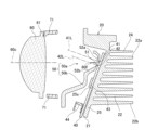
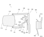
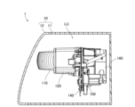
- the vehicle headlamp 1 of this embodiment mainly includes a housing 10 and a lamp unit LU. 1 is a side view of the vehicle headlamp 1, and FIG. 1 shows a cross section of the housing 10 for easy understanding.
- the housing 10 has a lamp housing 11 and a front cover 12 having optical transparency.
- the front of the lamp housing 11 is open, and a front cover 12 is fixed to the lamp housing 11 so as to close the opening.
- a space formed by the lamp housing 11 and the front cover 12 is a lamp chamber R, and the lamp unit LU is accommodated in the lamp chamber R.
- FIG. 2 is an exploded perspective view of the lamp unit LU seen obliquely from the front and above.
- FIG. 3 is an exploded perspective view of the lighting unit LU as seen obliquely from below.
- FIG. 4 is a vertical sectional view of the lamp unit LU.
- the lighting unit LU of this embodiment includes a heat sink 20, a fan 30 that is an axial fan, a substrate 40, a reflector unit 50, a projection lens 60, a holder 70, is provided as the main configuration.
- 4 is a vertical cross-sectional view of the lamp unit LU along the optical axis of the projection lens 60, which will be described later, and the illustration of the fan 30 is omitted in FIG.
- FIG. 5 is a perspective view of the heat sink 20 viewed obliquely from the front and above.
- the heat sink 20 is made of a material with excellent heat dissipation, such as metal.
- the heat sink 20 of this embodiment includes a base plate 21 on which a substrate 40 is arranged, a plurality of radiation fins 22, a plurality of mounting bosses 23a and 23b, and a peripheral wall portion 24. Provided as a main component.
- the base plate 21 is a plate-like member having a front surface located on the front side and a back surface located on the rear side, and has an inclined portion 25 that is inclined rearwardly upward.
- the inclined portion 25 is provided with a pedestal 25a projecting forward, and an end surface 25s of the pedestal 25a is a flat surface that is upwardly inclined rearward.
- a substrate 40 is arranged on the end face 25s.
- Protrusions 26 protruding forward are provided on both left and right sides of the base 25a.
- Pins 27 projecting forward are provided on the right and left sides of the base plate 21 relative to the pedestal 25a.
- the plurality of heat radiation fins 22, mounting bosses 23a and 23b, and peripheral wall portion 24 are arranged on the back surface of the base plate 21 opposite to the substrate 40 side, extend rearward, and are integrally formed with the base plate 21. .
- the fan 30 is arranged behind the plurality of radiating fins 22 and fixed to the mounting bosses 23a and 23b. The air blown by the fan 30 cools the heat sink 20 .
- the rear side of the heat sink 20 on which the plurality of radiation fins 22, mounting bosses 23a and 23b, the peripheral wall portion 24, and the fan 30 are arranged will be described later.
- the substrate 40 is a plate-like member made of metal, for example, and is arranged on the end face 25s of the base 25a of the heat sink 20, as described above.
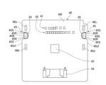
- FIG. 6 is a front view schematically showing the substrate 40.
- the outer shape of the substrate 40 is generally a symmetrical rectangular shape, and the substrate 40 has a pair of concave portions 45 in which left and right side surfaces 40sf facing each other are respectively recessed.
- the concave portion 45 has a substantially rectangular shape, and the side surfaces 40sf of the substrate 40 defining the concave portion 45 include a pair of straight portions 45S extending in the left-right direction and facing each other, and a tip in the direction of the depression extending in the vertical direction.
- the protrusions 26 of the heat sink 20 are inserted into the respective recesses 45 .
- the projection part 26 is shown by FIG.
- the vertical movement of the substrate 40 along the end surface 25 s is restricted by the pair of linear portions 45 S of the recess 45 and the outer peripheral surface of the protrusion 26 .
- the bottom 45B of one recess 45 and the outer peripheral surface of one protrusion 26, and the bottom 45B of the other recess 45 and the outer peripheral surface of the other protrusion 26 allow the substrate 40 to extend in the horizontal direction along the end face 25s. movement is restricted.
- the movement of the substrate 40 along the end surface 25 s is restricted by the concave portion 45 and the protrusion 26 , and the substrate 40 is positioned with respect to the heat sink 20 .
- the shape of the recess 45 is not particularly limited.
- the protrusion 26 may be press-fitted into the recess 45 .
- a first light source 41, a second light source 42, an integrated circuit 43, and a connector 44 are mounted on the front surface 40f of the substrate 40.
- the first light source 41 emits light forming a low-beam light distribution pattern from a planar emission surface.
- the second light source 42 emits light that forms a high beam light distribution pattern together with the light emitted from the first light source 41 from a planar emission surface.
- the first light source 41 and the second light source 42 are LED arrays composed of a plurality of LEDs (Light Emitting Diodes) arranged in the horizontal direction, and are arranged inside the bottom portion 45B of the concave portion 45 .
- the second light source 42 is positioned below the first light source and overlaps the recess 45 in the left-right direction, which is the direction in which the plurality of LEDs are arranged.
- the integrated circuit 43 is arranged below the second light source 42 and the connector 44 is arranged below the integrated circuit 43 .
- a circuit (not shown) is provided on the substrate 40, and the circuit connects the connector 44 and the first light source 41, the connector 44 and the integrated circuit 43, and the integrated circuit 43 and the second light source 42, respectively.
- Power is supplied to the connector 44 from a power supply unit (not shown). Therefore, power is supplied from the connector 44 to the first light source 41 , and power is supplied from the connector 44 to the second light source 42 via the integrated circuit 43 .
- the integrated circuit 43 includes a plurality of switch elements to individually adjust the power supplied to each LED of the second light source 42 .
- the integrated circuit 43 is not particularly limited as long as it can adjust the power supplied to at least one of the first light source 41 and the second light source 42 . Also, the arrangement of the integrated circuit 43 and the connector 44 is not particularly limited. Also, the integrated circuit 43 may not be mounted on the substrate 40, in which case the connector 44 and the second light source 42 are connected by a circuit.
- the portion of the substrate 40 where the first light source 41, the second light source 42, and the integrated circuit 43 are mounted overlaps the end surface 25s.
- the substrate 40 is also tilted, and the front surface 40f is tilted forward and upward.
- a normal 41L to the exit surface of the first light source 41 and a normal 42L to the exit surface of the second light source 42 are substantially perpendicular to the front surface 40f of the substrate 40 . Therefore, the perpendicular 41L and the perpendicular 42L face obliquely forward and upward.
- a perpendicular line 41L and a perpendicular line 42L shown in FIG. 4 are the same as a straight line that passes through the center of the emission surface, is parallel to the emission direction of the light with the highest intensity among the light emitted from the light source, and passes through the portion of the emission surface from which the light is emitted. is.
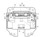
- FIG. 7 is a front view of the state in which the reflector unit 50 is attached to the heat sink 20, viewed from the front side, along the optical axis of the projection lens 60, which will be described later.
- the reflector unit 50 is arranged in front of the substrate 40 and the substrate 40 is sandwiched between the reflector unit 50 and the heat sink 20 .
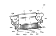
- the reflector unit 50 of this embodiment includes a light distribution forming portion 50a and a cover portion 50b connected to the left and right sides and the lower side of the light distribution forming portion 50a. It is formed.
- the light distribution forming portion 50a is surrounded by a dashed line.
- the reflector unit 50 is fixed to the heat sink 20 by fixing the cover portion 50 b to the heat sink 20 with screws 80 .
- the material forming the reflector unit 50 include plated metal, and the reflector unit 50 is formed by, for example, cutting and plating a metal member obtained by casting.
- the light distribution forming portion 50a of this embodiment includes a first reflector 51, a pair of second reflectors 52a and 52b, a pair of upper side reflectors 53a and 53b, and a pair of lower side reflectors 53a and 53b. It has reflectors 54a and 54b as a main configuration.
- the first reflector 51 is arranged between the first light source 41 and the second light source 42 and extends in the front-rear direction.
- the first reflector 51 has a tapered shape toward a front end 51e, and upper and lower surfaces of the first reflector 51 are reflecting surfaces 51ur and 51dr that reflect light.
- the upper reflecting surface 51ur which is the upper surface
- the lower reflective surface 51dr which is the lower surface, is positioned above the normal line 42L of the second light source 42 and curves concavely upward.
- the front end 51e of the first reflector 51 has a shape that matches the cutoff line of a low beam light distribution pattern, which will be described later, and is gradually recessed rearward from the left and right ends toward the center.
- the vertical line 41L of the first light source 41 and the vertical line 42L of the second light source 42 are directed obliquely forward and upward. 1 approach the reflector 51;
- One second reflector 52a is arranged above the first reflector 51 and has a reflecting surface 52ar on the first reflector 51 side.
- the second reflector 52a of this embodiment is a plate-like member, and the side surface of the plate-like member is the reflecting surface 52ar.
- the reflecting surface 52ar and the reflecting surface 51ur on the upper side of the first reflector 51 extend along the parallel direction of the plurality of LEDs that constitute the first light source 41, and are arranged so as to sandwich the plurality of LEDs from above and below. A pair of reflectors.
- the other second reflector 52b is arranged below the first reflector 51 and has a reflecting surface 52br on the first reflector 51 side.
- the second reflector 52b of this embodiment is a plate-like member, and one main surface of the plate-like member is the reflecting surface 52br.
- the reflecting surface 52br and the reflecting surface 51dr on the lower side of the first reflector 51 extend along the parallel direction of the plurality of LEDs constituting the second light source 42, and are arranged so as to sandwich the plurality of LEDs from above and below. a pair of reflectors that
- One upper side reflector 53a is positioned in the space sandwiched between the upper reflecting surface 51ur of the first reflector 51 and the reflecting surface 52ar of the second reflector 52a. formed at one end of the The other upper side reflector 53b is formed at the other end of the space.
- the pair of upper side reflectors 53a and 53b are formed such that the distance between them increases from the rear toward the front.
- An opening 55 surrounded by the pair of upper side reflectors 53a and 53b, the first reflector 51, and the second reflector 52a is formed in the light distribution forming portion 50a, and the emission surface 41s of the first light source 41 is Overlaps the opening 55 .
- reference numerals are given to one first light source 41 and the emission surface 41s, and the reference numerals for the others are omitted.
- One of the lower side reflectors 54a is located in the space sandwiched between the lower reflecting surface 51dr of the first reflector 51 and the reflecting surface 52br of the second reflector 52b. It is formed at one end in the parallel direction.
- the other lower side reflector 54b is formed at the other end of the space.
- the pair of lower side reflectors 54a and 54b are formed such that the distance between them increases from the rear toward the front.
- An opening 56 surrounded by the pair of lower side reflectors 54a and 54b, the first reflector 51, and the second reflector 52b is formed in the light distribution forming portion 50a, and the emission surface 42s of the second light source 42 is overlaps with the opening 56 at .
- the opening 56 and the opening 55 penetrate from a flat facing surface 50as of the light distribution forming portion 50a facing substantially parallel to the substrate 40 to the surface opposite to the substrate 40 side. Note that the facing surface 50as may not be flat.
- Through-holes 57 are provided on both left and right sides of the cover portion 50b of the present embodiment, and the pins 27 of the heat sink 20 are inserted into the through-holes 57 . Therefore, the reflector unit 50 can be positioned with respect to the heat sink 20 by the peripheral surface defining the through hole 57 and the pin 27 .
- the integrated circuit 43 and the connector 44 overlap the cover portion 50b in the direction perpendicular to the front surface 40f of the substrate 40. As shown in FIG. Therefore, when the substrate 40 is viewed from above, the cover portion 50 b covers the integrated circuit 43 and the connector 44 mounted on the substrate 40 . Further, as shown in FIG.
- the light distribution forming portion 50a and the cover portion 50b are provided with a plurality of ribs 58 projecting rearward.
- the tip of the rib 58 contacts the front surface 40 f of the substrate 40 , and the substrate 40 is pressed against the heat sink 20 by the reflector unit 50 and fixed to the heat sink 20 .
- portions 46a, 46b, 46c, and 46d where the reflector unit 50 presses the substrate 40 are indicated by diagonal hatching.
- the reflector unit 50 presses four portions 46a, 46b, 46c and 46d, the portions 46a and 46b being positioned outside the bottom portion 45B of one of the recessed portions 45, and the portions 46c and 46d pressing the other. is located outside the bottom portion 45B of the recessed portion 45 of the . Therefore, the reflector unit 50 presses the portion of the substrate 40 outside the bottom portion 45B of each concave portion 45 .
- the parts 46a and 46b are positioned above and below one recess 45 as a reference, and sandwich this one recess 45 in the direction along the side surface 40sf.
- the parts 46c and 46d are located above and below the other recess 45, and sandwich the other recess 45 in the direction along the side surface 40sf. Therefore, the reflector unit 50 presses both sides of each recess 45 in the substrate 40 . Also, the external shapes of the parts 46a, 46b, 46c, and 46d are substantially rectangular, but are not particularly limited.
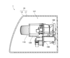
- the projection lens 60 is a lens that changes the divergence angle of transmitted light, and is arranged in front of the reflector unit 50 .
- the projection lens 60 is a biconvex aspherical lens having an outer shape elongated in the left-right direction and having a substantially oval track shape.
- a flange portion 61 is provided that extends along the length thereof.
- An optical axis 60 c of the projection lens 60 extends in the front-rear direction, intersects the first reflector 51 , and passes between the first light source 41 and the second light source 42 .
- the rear focal point 60f of the projection lens 60 is located near the front end 51e between the front end 51e of the first reflector 51 and the projection lens 60. is 10 mm or less. Note that the focal point 60f may be positioned at the front end 51e or may overlap the first reflector 51.
- FIG. Examples of the material forming the projection lens 60 include resin, glass, and the like.
- the holder 70 of this embodiment includes a cylindrical support portion 71 extending in the front-rear direction and a pair of legs extending rearward from the left and right sides of the rear end of the support portion 71. 72.
- a plurality of pedestals 73 projecting forward are provided at the front end of the support portion 71, and the flange portion 61 of the projection lens 60 is fixed to the pedestals 73 by, for example, ultrasonic welding or laser welding.
- the legs 72 are fixed to the heat sink 20 by screws 81 and the projection lens 60 is fixed to the heat sink 20 via the holder 70 .
- a resin such as opaque polycarbonate can be used.
- FIG. 10 is a back view of the heat sink 20.
- FIG. A plurality of radiation fins 22 of the heat sink 20 are arranged in parallel with a space therebetween and extend in the left-right direction. In each figure, for ease of viewing, only one of each of the radiating fins 22 and the gaps 500 between the mutually adjacent radiating fins 22 is labeled.
- the uppermost radiating fin is designated as radiating fin 22a
- the lowest radiating fin is designated as radiating fin 22b.
- the radiation fins 22 refer to the radiation fins 22a, 22b and the radiation fins positioned between the radiation fins 22a, 22b and extending in the horizontal direction.
- the left and right sides of the heat radiation fins 22 and the upper side of the heat radiation fins 22a are surrounded by the peripheral wall portion 24.
- the peripheral wall portion 24 is a frame surrounding the radiation fins 22 as described above and is separated from the radiation fins 22 .
- the left and right walls of the peripheral wall portion 24 are shorter than the radiating fins 22 and the upper wall is longer than the radiating fins 22 in the front-rear direction.
- a fan 30 is provided behind the plurality of heat radiation fins 22.
- the fan 30 mainly includes an impeller 31 provided on the side opposite to the base plate 21 with respect to the plurality of radiation fins 22 and a support unit 33 .
- illustration of the impeller 31 is omitted in FIGS. 2 and 3 .
- FIG. 10 is also a view of the impeller 31 viewed along the rotation axis R1.
- Each of the impeller 31 and the support unit 33 is made of resin, for example.
- the impeller 31 rotates around a rotation axis R1 along a direction perpendicular to the back surface of the base plate 21. Also, the impeller 31 rotates along the back surface of the base plate 21 to send air to the gaps 500 between the adjacent radiation fins 22 .
- the impeller 31 of this embodiment rotates counterclockwise.
- the impeller 31 is rotatably supported by the support unit 33 .
- the support unit 33 mainly includes a base member 33a on which the impeller 31 is arranged, and a support member 33b provided on the side of the impeller 31 and the base member 33a when the fan 30 is viewed from the rear.
- the base member 33 a is a circular plate-like member and is arranged in front of the impeller 31 .
- the base member 33a is connected to the support member 33b via spokes 33c that are connected to the outer peripheral surface of the base member 33a and the inner peripheral surface of the support member 33b. Therefore, the support member 33b rotatably supports the impeller 31 via the base member 33a and the spokes 33c.
- illustration of the spokes 33c is omitted in FIG.
- the support member 33b is an outer frame that encloses the sides of the impeller 31 and the base member 33a, and is formed in a substantially square shape. In the support member 33b of the present embodiment, two substantially parallel sides of the substantially square support member 33b extend in the left-right direction.
- the support member 33b is shorter than the heat radiating fins 22 in the horizontal direction and longer than the space between the heat radiating fins 22a and 22b in the vertical direction.
- the front surfaces of the base member 33a and the support member 33b are in contact with the rear ends of the radiation fins 22, but may be separated from the rear ends.
- the four corners of the support member 33b are rounded.
- Through holes 33d are provided in the upper right and lower left corners of the four corners of the support member 33b, screws 501 are inserted into the through holes 33d, and the screws 501 are screwed into the mounting bosses 23a and 23b. Thereby, the fan 30 is attached to the heat sink 20 via the support member 33b and the attachment bosses 23a and 23b.
- FIG. 10 the mounting bosses 23a and 23b are hidden by the fan 30 and cannot be seen, but are illustrated with broken lines for easy understanding.
- a straight line passing through the rotation axis R1 and extending in the extending direction of the radiation fins 22 is indicated as a first reference line 503a
- a straight line passing through the rotation axis R1 and extending in a direction orthogonal to the first reference line 503a is indicated as a first reference line 503a. It is shown as a second reference line 503b.
- Four areas are formed by the reference lines 503a and 503b, and areas 510a, 510b, 510c, and 510d are shown as upper right, upper left, lower left, and lower right areas with respect to the rotation axis R1.
- each region is shown slightly displaced from the reference lines 503a and 503b.
- the regions 510a and 510b and the regions 510c and 510d are regions adjacent to each other in the extending direction of the radiation fins 22. . Further, since the impeller 31 rotates counterclockwise, the region 510a in the regions 510a and 510b and the region 510c in the regions 510c and 510d are regions on the rear side of the impeller 31 in the rotation direction.
- the mounting bosses 23a are provided in the rear region 510a, and the mounting bosses 23b are provided in the rear region 510c.
- mounting bosses 23a, 23b are provided in respective rear regions 510a, 510c. At least part of the mounting boss 23a should be provided in the rear area 510a, and at least part of the mounting boss 23b should be provided in the rear area 510c.
- the support member 33b is attached to the attachment bosses 23a and 23b as described above. Therefore, when the fan 30 is viewed from the rear, the mounting bosses 23 a and 23 b are located on the sides of the impeller 31 . Further, since through holes 33d are provided in the upper right and lower left corners of the support member 33b, the mounting boss 23a overlaps the upper right corner and the mounting boss 23b overlaps the lower left corner.
- the mounting boss 23a is located between the first reference line 503a and the radiating fin 22a farthest upward from the first reference line 503a, specifically, the gap between the radiating fin 22a and the radiating fin 22 adjacent to the radiating fin 22a. Located at 500.
- the mounting boss 23b is located outside the heat radiating fin 22b on the side opposite to the gap 500 side.
- the mounting bosses 23a and 23b positioned as described above do not overlap each other along the extending direction of the radiation fins 22. As shown in FIG.
- the mounting boss 23a is connected to the heat radiating fin 22a and the heat radiating fin 22 adjacent to the heat radiating fin 22a, and the mounting boss 23b is connected to the heat radiating fin 22b.
- the mounting bosses 23 a and 23 b may be connected to at least one of the mutually adjacent radiation fins 22 forming the gap 500 or may be separated from the radiation fins 22 .
- the impellers in the regions 510a and 510b adjacent to each other in the extending direction of the radiating fin 22 31 is shown as a predetermined area 520a.
- some of the LEDs of the first light source 41 overlap the predetermined area 520a.
- At least one LED of the first light source 41 may overlap at least part of the predetermined area 520a.
- Most of the wind flowing through the gap 500 flows toward the end side of the gap 500 overlapping the above-described region 510b under the influence of the vortex of the airflow caused by the rotation of the impeller 31 .
- the predetermined area 520 a is cooled more easily than the area outside the predetermined area 520 a , and the heat generated by the first light source 41 overlapping the predetermined area 520 a is easily transferred to the radiation fins 22 .
- the predetermined area 520 a is used, but even if the first light source 41 overlaps the predetermined area 520 b as described above, the heat generated by the first light source 41 is easily transmitted to the heat dissipation fins 22 .
- the predetermined region 520b is defined between the first reference line 503a and the radiating fin 22b farthest downward from the first reference line 503a, and the impeller 31 between the regions 510c and 510d adjacent to each other in the extending direction of the radiating fin 22.
- the first light source 41 may overlap both of the predetermined regions 520a and 520b. Although the first light source 41 has been described above, the second light source 42 may overlap the predetermined areas 520a and 520b in the same manner as the first light source 41 does.
- the structure 600 includes a conductive member 601 that supplies power to the fan 30 , and the conductive member 601 includes power supply wiring 605 including a connector 603 .
- a fan-side connector 35 a of the fan-side wiring 35 extending from the fan 30 is connected to the connector 603 . Also, the connector 603 is fixed to the rear surface of the base plate 21 between the left wall of the peripheral wall portion 24 and the heat radiation fins 22 .
- a part of the power supply side wiring 605 is supported by a clamp 630 .
- Clamp 630 includes a holding portion 631 and a hook portion 633 .
- the holding portion 631 has a substantially concave shape when the fan 30 is viewed from the rear, and is connected to the hook portion 633 .
- the hooking portion 633 is hooked to the receiving member 22c by sandwiching the left and right surfaces of the receiving member 22c located in the region 510d.
- the receiving member 22 c is a plate-like member and is provided on the back surface of the base plate 21 .
- the receiving member 22c is connected to the surface of the radiation fin 22b on the side opposite to the gap 500 side.
- the receiving member 22c may dissipate heat as heat dissipating fins.
- the power-supply-side wiring 605 passes through the holding portion 631 in the front-rear direction and is hooked on the holding portion 631 , so that the holding portion 631 holds the power-supply-side wiring 605 .
- the power supply wiring 605 further extends rearward from the holding section 631 and is connected to a power supply section (not shown). When the power supply unit supplies power to the fan 30 via the power supply wiring 605 and the fan wiring 35, the fan 30 rotates.
- the structure 600 is located in areas 710c and 710d other than areas 710a and 710b on the leeward side of the wind passing through the gap 500 in the extending direction of the heat radiating fins 22 when the fan 30 is viewed from the rear.
- regions 710a, 710b, 710c, and 710d are shown slightly displaced from the other regions described above for ease of viewing. Regions 710a, 710b, 710c, and 710d are described below.
- a region 710a is a region on the left side of the gap 500 between the heat radiating fins 22 adjacent to each other and on the left side of the heat radiating fins 22 provided above the first reference line 503a in the region 510b.
- the region 710b of the present embodiment is a region on the right side of the gap 500 between the adjacent heat dissipating fins 22 provided below the first reference line 503a in the region 510d and on the right side of the heat dissipating fins 22 .
- Regions 710c and 710d are regions on the rear surface side of the base plate 21 outside the regions surrounded by the radiation fins 22a and 22b, excluding the regions 710a and 710b.
- the area 710c is an area provided above a straight line parallel to the first reference line 503a and passing through the heat radiation fins 22a and above the area 710b.
- the area 710d is an area provided below a straight line parallel to the first reference line 503a and passing through the radiation fins 22b and below the area 710a.
- FIG. 10 shows an example in which the conductive member 601 and the clamp 630 are arranged in the region 710d, and are not arranged in the regions 710a and 710b. be provided. Note that the conductive member 601 and the clamp 630 may be provided in the region 710c. The conductive member 601 and the clamp 630 are located at a position lower than the rear end of the radiation fin 22 in the front-rear direction. The conductive member 601 is arranged apart from the heat radiating fins 22 .
- the mounting bosses 23a and 23b are located on the sides of the impeller 31 in the regions 510a and 510c on the rear side of the impeller 31 in the rotational direction.
- the wind flows in the opposite direction to the mounting boss 23a. Therefore, the mounting boss 23a is provided outside the traveling path of the wind flowing through the gap 500, and is provided at a position where the wind is not blocked. It will be.
- blocking of the air by the mounting boss 23 a is suppressed, and the air flowing through the gap 500 where the mounting boss 23 a is positioned is blown out to the left side of the heat radiating fin 22 through the gap 500 .
- the wind flows in the opposite direction to the mounting bosses 23b. As a result, blocking of the wind by the mounting boss 23b is also suppressed.
- the air tends to be blown to the left side of the heat radiating fins 22 in the gaps 500 other than the gaps 500 where the mounting bosses 23a are located, in the gaps 500 above the first reference line 503a. Also, in the gap 500 below the first reference line 503a, the air tends to be blown out to the right side of the radiation fin 22. As shown in FIG.
- the conductive member 601 and the clamp 630 are located in a region 710d other than the regions 710a and 710b on the leeward side of the wind passing through the gap 500 in the extending direction of the heat radiating fins 22. Accordingly, the conductive member 601 and the clamp 630 are provided outside the traveling path of the wind passing through the gap 500, and are provided at a position where the wind is not blocked. As a result, the wind is blown out to the side of the radiation fins 22 while the blocking of the wind by these is suppressed.
- FIG. 11 is an enlarged view of part of FIG. 4 and schematically shows an example of optical paths of light emitted from the first light source 41 and light emitted from the second light source 42 . Note that the reflection angle, refraction angle, and the like of light shown in FIG. 11 may not be accurate.
- the first light source 41 When forming a low-beam light distribution pattern, light is emitted from the first light source 41 .
- Part of the light L1a emitted from the first light source 41 passes between the upper reflecting surface 51ur of the first reflector 51 and one of the second reflectors 52a and directly enters the projection lens 60 .
- Another part of the light L1b emitted from the first light source 41 is reflected toward the projection lens 60 at a portion including the front end of the upper reflecting surface 51ur of the first reflector 51, and enters the projection lens 60. do.
- Another part of the light L1c emitted from the first light source 41 is reflected by the reflecting surface 52ar of one of the second reflectors 52a, and the part including the front end of the upper reflecting surface 51ur of the first reflector 51 is reflected toward the projection lens 60 and enters the projection lens 60 .
- the front end 51e of the first reflector 51 has a shape that matches the cutoff line. A cutoff line is formed in the light distribution pattern. Also, although not illustrated, part of the light emitted from the first light source 41 that diffuses in the horizontal direction is reflected by the pair of upper side reflectors 53 a and 53 b and enters the projection lens 60 . .
- the light emitted from the first light source 41 and directly incident on the projection lens 60 and the light emitted from the first light source 41 and reflected by the reflector unit 50 and incident on the projection lens 60 form a low-beam light distribution.
- a pattern is formed.
- the light having this low-beam light distribution pattern is transmitted through the projection lens 60 and emitted from the vehicle headlamp 1 via the front cover 12 .
- the light distribution pattern of the low beam projected forward of the vehicle is a light distribution pattern that is inverted by the projection lens 60. be.
- the light L1a that directly enters the projection lens 60 is light emitted mainly in a direction parallel to the normal 41L.
- Light L1b reflected by the first reflector 51 and incident on the projection lens 60 and light L1c reflected by the second reflector 52a and reflected by the first reflector 51 and incident on the projection lens 60 are mainly different from the perpendicular line 41L. This is light emitted in parallel directions.
- the light L1a may include light emitted in a direction non-parallel to the normal 41L
- the light L1c may include light emitted in a direction parallel to the perpendicular 41L.
- FIG. 12 is a diagram showing a low beam light distribution pattern in this embodiment.
- S indicates a horizontal line
- V indicates a vertical line passing through the center of the vehicle in the left-right direction
- the low-beam light distribution pattern PL projected onto a virtual vertical screen placed 25 m in front of the vehicle is indicated by a thick line.
- the reflector unit 50 is shaped so that the light distribution pattern of the light from the first light source 41 incident on the projection lens 60 becomes such a low-beam light distribution pattern PL.
- the cutoff line CL of the low-beam light distribution pattern PL corresponds to the shape of the front end 51e of the first reflector 51, and has a step in this embodiment.
- the light from the first light source 41 forms the low-beam light distribution pattern PL
- the vehicle headlamp 1 emits light having the low-beam light distribution pattern PL.
- Part of the light L2a emitted from the second light source 42 directly enters the projection lens 60 through the space between the lower reflecting surface 51dr of the first reflector 51 and the other second reflector 52b.
- Another portion of the light L2b emitted from the second light source 42 is reflected toward the projection lens 60 at a portion including the front end portion of the lower reflecting surface 51dr of the first reflector 51, and is reflected toward the projection lens 60.
- FIG. 1 Another portion of the light L2c emitted from the second light source 42 is reflected toward the projection lens 60 by the reflecting surface 52br of the other second reflector 52b, and enters the projection lens 60.
- FIG. of the light emitted from the second light source 42 the light passing through the vicinity of the front end 51e of the first reflector 51 causes the light distribution pattern formed by the light emitted from the second light source 42 to have a cutoff line corresponding to the front end 51e. It is formed.
- part of the light emitted from the second light source 42 that diffuses in the horizontal direction is reflected by the pair of lower side reflectors 54a and 54b and enters the projection lens 60. do.
- This additional light distribution pattern is a light distribution pattern in which a high beam light distribution pattern is formed by being added to the low beam light distribution pattern PL. , and the light emitted from the first light source 41 to form a high beam light distribution pattern.
- an additional light distribution pattern is formed by the light from the second light source 42 , and the light having this additional light distribution pattern is transmitted through the projection lens 60 and emitted from the vehicle headlamp 1 through the front cover 12 . be done.
- the additional light distribution pattern projected forward of the vehicle is a light distribution pattern that is reversed by the projection lens 60, like the low beam light distribution pattern PL.
- the cutoff line of the additional light distribution pattern is defined by the front end 51e of the first reflector 51, similarly to the cutoff line CL of the low beam light distribution pattern PL. Therefore, the cutoff line of the additional light distribution pattern and the cutoff line CL of the light distribution pattern PL of the low beam approximately match, and the light distribution pattern of the high beam is a combination of the additional light distribution pattern and the light distribution pattern PL of the low beam. becomes.
- the upper side of the low-beam light distribution pattern PL and the lower side of the additional light distribution pattern overlap, but the low-beam light distribution pattern PL and the additional light distribution pattern do not have to overlap.
- at least part of the cutoff line of the additional light distribution pattern and at least part of the cutoff line CL of the low beam light distribution pattern PL match, and the additional light distribution pattern and the low beam light distribution pattern PL are connected.
- the light L2a that directly enters the projection lens 60 is light emitted mainly in a direction parallel to the normal 42L.
- Light L2b reflected by the first reflector 51 and incident on the projection lens 60 and light L2c reflected by the second reflector 52a and incident on the projection lens 60 are mainly emitted in a direction non-parallel to the perpendicular 42L.
- the light L2a may include light emitted in a direction non-parallel to the normal 42L
- the light L2b may include light emitted in a direction parallel to the perpendicular 42L.
- the additional light distribution pattern can be changed, and the light distribution pattern of the high beam can be changed. can be changed.
- FIG. 13 is a diagram showing the light distribution pattern of the high beam in this embodiment, and is a diagram showing the light distribution pattern of the high beam in the same manner as in FIG.
- the high beam light distribution pattern PH shown in FIG. 13 is for the case where light is emitted from all the LEDs that constitute the second light source 42 .
- the cutoff line CL in the low-beam light distribution pattern PL is indicated by a dotted line.
- a region below the cutoff line CL in the light distribution pattern PH of the high beam is formed mainly by the light from the first light source, and a region above the cutoff line CL is formed mainly by the light from the second light source 42 .
- the substrate 40 on which the first light source 41 and the second light source 42 are mounted has recesses 45 in which the side surfaces 40sf facing each other are respectively recessed. .
- the reflector unit 50 presses a portion of the substrate 40 outside the bottom portion 45B of each concave portion 45 . Therefore, the strength of the portion outside the bottom 45B of each recess 45 in the substrate 40 is weakened compared to the case where the substrate 40 does not have the recess 45, and the reflector unit 50 has such strength. Press the weakened area.
- the distortion of the substrate 40 due to the pressing force of the reflector unit 50 can be concentrated on the portion where the strength is weakened. , the strain inside the bottom portion 45B of the recess 45 can be reduced. Further, in the vehicle headlamp 1 of the present embodiment as the first aspect, the first light source 41 and the second light source 42 are positioned inside the bottom portion 45B of the recess 45 . Therefore, according to the vehicle headlamp 1 of the present embodiment as the first aspect, the orientations of the first light source 41 and the second light source 42 change due to the distortion of the substrate 40 compared to the above case. can be suppressed, and a light distribution pattern of low beam and high beam can be easily formed.
- the reflector unit 50 presses the concave portion 45 side on one side and the concave portion 45 side on the other side of the substrate 40 .
- the substrate 40 and the heat sink 20 are more likely to be separated from each other. It is possible to suppress the displacement of the relative position and facilitate formation of a light distribution pattern of low beam and high beam.
- the reflector unit 50 presses both sides of each recess 45 in the substrate 40 .
- the substrate 40 and the heat sink are more likely to be separated from each other. It is possible to suppress the displacement of the relative position with 20 .
- the reflector unit 50 has a flat facing surface 50as facing the substrate 40, and a surface from the facing surface 50as to the surface opposite to the substrate 40 side. It has openings 55 and 56 therethrough.
- the first light source 41 overlaps the aperture 55 and the aperture 56 overlaps the second light source 42 . Therefore, according to the vehicle headlamp 1 of the present embodiment as the first aspect, the facing surface 50as can be formed more easily by cutting than, for example, when the facing surface 50as is not flat.
- the integrated circuit 43 for adjusting the power supplied to at least one of the first light source 41 and the second light source 42 and the connector 44 are formed on the substrate 40. , and the integrated circuit 43 and the connector 44 are covered by the reflector unit 50 . Therefore, according to the vehicle headlamp 1 of the present embodiment as the first aspect, it is possible to suppress the irradiation of the integrated circuit 43 with sunlight or the like that enters from the outside through the projection lens 60 .
- the bright parts in the low beam light distribution pattern and the high beam light distribution pattern greatly affect visibility.
- the vicinity of the cutoff line in the light distribution pattern for low beams is bright, and the vicinity of the center of the light distribution pattern for high beams is bright.
- the light emission surfaces of the first light source and the second light source are planar, the first light source and the second light source are mounted on different substrates, and the first light source and the second light source are mounted on different substrates.
- a normal to the exit surface of each of the second light sources approaches the first reflector toward the front.
- the luminous flux of light emitted from a light source having a planar emission surface tends to increase as it approaches the perpendicular line of the emission surface.
- the light from the first light source can brighten the front end portion of the upper surface of the first reflector, and can brighten the vicinity of the cutoff line in the light distribution pattern of the low beam.
- the light from the second light source can brighten the front end portion of the lower surface of the first reflector, brighten the low-beam light distribution pattern side of the additional light distribution pattern, and brighten the vicinity of the center of the high-beam light distribution pattern.
- the first light source and the second light source are mounted on different substrates, so the number of parts tends to increase.
- the first light source 41 and the second light source 42 are mounted on the common substrate 40, so that the first light source 41 and the second light source 42 are The number of parts can be reduced as compared with the case where they are mounted on different substrates.
- the perpendicular 41L of the emission surface 41s of the first light source 41 is the same as that of the emission surfaces of the first light source and the second light source in the first patent document. Unlike the vertical line, it moves away from the first reflector 51 toward the front. Therefore, the luminous flux of the light L1b emitted from the first light source 41 and directly incident on the front end of one reflecting surface 51ur of the first reflector 51 tends to decrease, making it difficult to brighten the front end. However, the light L1c emitted from the first light source 41 and reflected by the second reflector 52a also enters the front end portion of the reflecting surface 51ur of the first reflector 51 together with the light L1b.
- the vehicle headlamp 1 of the present embodiment as the second aspect can suppress the front end portions of the upper and lower surfaces of the first reflector 51 from becoming dark.
- the vehicle headlamp 1 of the present embodiment it is possible to suppress the vicinity of the cutoff line CL in the light distribution pattern PL of the low beam and the vicinity of the center of the light distribution pattern PH of the high beam from becoming dark, thereby improving visibility. can suppress the decrease in
- the light L1c which is the part of the light emitted from the first light source 41, diverges at the divergence angle of the second reflector 52a. is made smaller than when is incident and reflected toward the first reflector 51 . Therefore, according to the vehicle headlamp 1 of the present embodiment as the second aspect, it is possible to further suppress darkening in the vicinity of the cutoff line CL in the light distribution pattern PL of the low beam.
- the reflecting surface 52ar of the second reflector 52a that reflects the light L1c is a part of the spheroid, and one focal point of the spheroid is at the front end of the reflecting surface 51ur of the first reflector 51.
- the other focal point is located at the intersection of the exit surface 41s of the first light source 41 and the vertical line 41L.
- the shape of the reflecting surface 52ar is not particularly limited. Another part of the light L1c may be reflected toward the first reflector 51 with a divergence angle that is the same as or greater than that when incident on one of the second reflectors 52a.
- the other part of the light L2c out of the light emitted from the second light source 42 is emitted from the other second reflector 52b. It is reflected towards projection lens 60 with a greater divergence angle than when incident. Therefore, according to the vehicle headlamp 1 of the present embodiment as the second aspect, the light distribution pattern PH of the high beam can be easily widened upward. Another part of the light L2c may be reflected toward the projection lens 60 with the same or smaller divergence angle than when incident on the other second reflector 52b.
- the vehicle headlamp 1 of the present embodiment as a second aspect includes an integrated circuit 43 mounted on the substrate 40 and adjusting power supplied to at least one of the first light source 41 and the second light source 42. Prepare more.
- the reflector unit 50 has a cover portion 50 b that covers the integrated circuit 43 . Therefore, according to the vehicle headlamp 1 of the present embodiment, it is possible to suppress the irradiation of the integrated circuit 43 with sunlight or the like that enters from the outside through the projection lens 60 .
- the first aspect of the present invention has been described using the first embodiment as an example, the first aspect of the present invention is not limited to this.
- the heat sink 20 having the protrusions 26 to be inserted into the respective recesses 45 was described as an example.
- the heat sink 20 may not have the protrusions 26 .
- the reflector unit 50 that presses both sides of each concave portion 45 in the substrate 40 has been described as an example.
- the reflector unit 50 may press the portion of the substrate 40 outside the bottom portion 45 ⁇ /b>B, which is the tip of each concave portion 45 in the concave direction.
- the reflector unit 50 may press one side of each recess 45 in the substrate 40, for example, may press only the portions 46a and 46c shown in FIG. 6, or may press only the portions 46b and 46d. good.
- the reflector unit 50 may further press the portion of the substrate 40 inside the recess 45 .
- the substrate 40 having the recesses 45 on each side was described as an example.
- the substrate 40 only needs to have recesses 45 in which side surfaces facing each other are recessed.
- one side and the other side of the substrate 40 may have a plurality of recesses 45 , and the number of recesses 45 on one side may differ from the number of recesses 45 on the other side.
- the substrate 40 on which the first light source 41 and the second light source, which are LED arrays, are mounted has been described as an example.
- the light source mounted on the substrate 40 is not particularly limited.
- the reflector unit 50 that covers the connector 44 mounted on the substrate 40 has been described as an example. However, as a first aspect, the reflector unit 50 does not have to cover the connector 44 as shown in FIG.
- FIG. 14 is a diagram similar to FIG. 7 showing a state in which the reflector unit 50 is attached to the heat sink 20 in the first modified example as the first mode, and FIG. 15 shows the lamp unit LU in the first modified example.
- FIG. 5 is a view similar to FIG. 4; Constituent elements that are the same as or equivalent to those of the above-described embodiment are denoted by the same reference numerals, and overlapping descriptions are omitted unless specifically described.
- the shape of the cover portion 50b is different from that of the first embodiment.
- the cover portion 50b of the reflector unit 50 of this modified example is not formed on the lower side of the connector 44 in the direction along the front surface 40f of the substrate 40, which is the side opposite to the first light source 41 and the second light source 42 side. Therefore, compared to the case where the reflector unit 50 is formed on the opposite side of the connector 44 from the first light source 41 and the second light source 42 side, it is possible to easily connect other connectors to the connector 44 .
- the cover portion 50b does not cover the connector 44 when the substrate 40 is viewed from above, it is possible to make it easier to connect another connector to the connector 44 .
- a flat facing surface 50as of the light distribution forming portion 50a that faces the front surface 40f of the substrate 40 in a substantially parallel manner extends to the outer edge of the surface of the reflector unit 50 on the substrate 40 side. Therefore, for example, the facing surface 50as can be easily formed by cutting.
- the vehicle headlamp 1 as the lamp has been described as an example.
- the lighting fixture as the first aspect includes a substrate on which a light source is mounted, a heat sink on which the substrate is arranged, and a reflector that presses the substrate against the heat sink and reflects part of the light emitted from the light source. All you have to do is
- the lamp as the first aspect may not be for vehicles, and may emit light that forms a predetermined image.
- the second aspect of the present invention has been described with the first embodiment as an example, but the second aspect of the present invention is not limited to this.
- the first light source 41 in which the perpendicular 41L moves forward and away from the first reflector 51, and the second light source in which the perpendicular 42L approaches the first reflector 51 forward have been described as examples.
- the normal to one light source of the first light source 41 and the second light source 42 moves forward away from the first reflector 51, and the normal to the other light source moves forward from the first reflector 51.
- the vertical line 41L of the first light source 41 may move forward toward the first reflector 51
- the vertical line 42L of the second light source 42 may move forward and away from the first reflector 51.
- the first light source 41 and the second light source which are LED arrays, have been described as an example.
- the emission surfaces of the first light source 41 and the second light source are not particularly limited as long as they have flat plate-like emission surfaces.
- FIG. 16 is a diagram showing an optical path example of light emitted from the first light source 41 and light emitted from the second light source 42 in the second modified example as the second mode, similarly to FIG. Note that the reflection angle, refraction angle, etc. of light shown in FIG. 16 may not be accurate.
- the same or equivalent components as those of the first embodiment are denoted by the same reference numerals, and overlapping descriptions will be omitted unless specifically described.
- the substrate 40 is tilted upward and forward, and the light distribution forming portion 50a of the reflector unit 50 is vertically different from the light distribution forming portion 50a of the above-described embodiment. It is assumed that the shape is reversed to .
- part of the light L1a emitted from the first light source 41 passes between the upper reflecting surface 51ur of the first reflector 51 and one of the second reflectors 52a, and passes directly to the projection lens 60.
- the other portion of the light L1b is reflected toward the projection lens 60 at a portion including the front end portion of the upper reflecting surface 51ur of the first reflector 51 and enters the projection lens 60 .
- Another part of the light L1c is reflected toward the projection lens 60 by the reflecting surface 52ar of the second reflector 52a and enters the projection lens 60.
- part of the light emitted from the second light source 42 and diffused in the horizontal direction is reflected by the pair of lower side reflectors 54a and 54b in the same manner as in the above embodiment. and enters the projection lens 60 .
- the light emitted from the first light source 41 and directly incident on the projection lens 60 and the light emitted from the first light source 41 and reflected by the reflector unit 50 and incident on the projection lens 60 are combined as shown in FIG.
- a low-beam light distribution pattern PL shown is formed.
- the vertical line 41L of the first light source 41 approaches the first reflector 51 toward the front. can. Therefore, according to the vehicle headlamp 1 of the present modification as the second aspect, it is possible to suppress the vicinity of the cutoff line CL from becoming dark in the light distribution pattern PL of the low beam, thereby suppressing deterioration in visibility. can.
- Part of the light L2a emitted from the second light source 42 passes between the lower reflecting surface 51dr of the first reflector 51 and the second reflector 52b and directly enters the projection lens 60.
- the other portion of the light L2b is reflected toward the projection lens 60 at a portion including the front end portion of the lower reflecting surface 51dr of the first reflector 51 and enters the projection lens 60 .
- Another portion of the light L2c is reflected by the reflecting surface 52br of the second reflector 52b and is reflected toward the projection lens 60 at a portion including the front end portion of the reflecting surface 51dr of the first reflector 51 .
- part of the light emitted from the second light source 42 that is diffused in the left-right direction is partly reflected by the pair of lower side reflectors 54a and 54b, as in the first embodiment. It is reflected and enters the projection lens 60 .
- This additional light distribution pattern is a light distribution pattern in which a high beam light distribution pattern is formed by being added to the low beam light distribution pattern PH.
- a high beam light distribution pattern PH shown in is formed.
- the luminous flux of the light L2b emitted from the second light source 42 and directly incident on the front end of the reflecting surface 51dr of the first reflector 51 tends to decrease, making it difficult to brighten the front end.
- the light L2c emitted from the second light source 42 and reflected by the second reflector 52b also enters the front end portion of the reflecting surface 51dr of the first reflector 51 together with the light L2b. Reflected towards 60 . Therefore, even with such a second light source 42, it is possible to prevent the front end portion of the reflecting surface 51dr, which is the lower surface of the first reflector 51, from becoming dark. Therefore, according to the vehicle headlamp 1 of the present modification as the second aspect, it is possible to suppress the vicinity of the center of the light distribution pattern PH of the high beam from becoming dark, thereby suppressing deterioration of visibility.
- the vehicle headlamp 1 of this modified example as the second mode can reduce the number of parts while suppressing deterioration of visibility, as in the first embodiment.
- the light L1c which is part of the light emitted from the first light source 41, is directed toward the projection lens 60 with a larger divergence angle than when incident on the second reflector 52a. reflected by Therefore, according to the vehicle headlamp 1 of the present modified example as the second mode, the light distribution pattern PL of the low beam can be easily widened downward. Another part of the light L1c may be reflected toward the projection lens 60 with the same or smaller divergence angle than when incident on the second reflector 52a.
- the light L2c which is part of the light emitted from the second light source 42, has a smaller divergence angle than when incident on the second reflector 52b, and reaches the first reflector 51. reflected towards. Therefore, according to the vehicle headlamp 1 of the present modified example as the second aspect, it is possible to further suppress the darkening of the vicinity of the center of the light distribution pattern PH of the high beam.
- the reflecting surface 52br of the second reflector 52b that reflects the light L2c is a part of the spheroid, and one focal point of the spheroid is at the front end of the reflecting surface 51dr of the first reflector 51.
- the other focus is located at the center of the exit surface 42 s of the second light source 42 .
- the shape of the reflecting surface 52br is not particularly limited. Another part of the light L2c may be reflected toward the first reflector 51 with a divergence angle that is the same as or greater than when incident on the second reflector 52b.
- the reflector unit 50 having the cover portion 50b covering the integrated circuit 43 and the connector 44 has been described as an example.
- the cover portion 50b may not cover at least one of the integrated circuit 43 and the connector 44, and the reflector unit 50 may not have the cover portion 50b.
- the substrate 40 having the concave portion 45 into which the protrusion 26 of the heat sink 20 is inserted has been described as an example.
- the substrate 40 may not have the recess 45 .
- the reflector unit 50 that presses the substrate 40 against the heat sink 20 has been described as an example.
- the reflector unit 50 may not press the substrate 40 against the heat sink 20, in which case the substrate 40 is fixed to the heat sink 20 by screws, for example.
- FIG. 17 is a schematic diagram of a vehicle headlamp according to this embodiment. As shown in FIG. 17, in the vehicle headlamp 1 of the present embodiment, the configuration of the lighting unit LU is different from that of the lighting unit LU of the first embodiment.
- FIG. 18 is an exploded perspective view of the lamp unit LU shown in FIG.
- the lighting unit LU includes a projection lens 110, a lens holder 120, a reflector unit 130, a substrate 140, a heat sink 150, and a cooling fan 160.
- the projection lens 110 of this embodiment has a lens main body portion 111 and a flange-like fixing portion 112 provided on the outer periphery of the lens main body portion 111 .
- the lens body 111 has a light exit surface 113 that is convex and an incident surface 114 that has a smaller curvature than the light exit surface 113 .
- the lens main body 111 has a shape in which the upper and lower portions of a circular lens when viewed from the front are cut in a plane shape, and is thin in the vertical direction. It should be noted that the focal plane of the projection lens 110 is generally aligned with the light exit plane of the light emitting element, which will be described later.
- the lens holder 120 has a substantially square tubular shape that matches the outer shape of the lens main body 111, and includes a bottom plate 121, side plates 122 connected to both lateral edges of the bottom plate 121, and It has a top plate portion 123 facing the bottom plate portion 121 and connected to each of the side plate portions 122 .
- the bottom plate portion 121 and the top plate portion 123 extend substantially horizontally, and the side plate portion 122 extends substantially vertically.
- FIG. 19 is a diagram showing the reflector unit 130 in this embodiment.
- the reflector unit 130 is made of metal, and as shown in FIGS. 18 and 19, has a reflecting portion 131, a light shielding cover 132, a fixing portion 134, and a blind plate 135 as main components. Further, the reflector unit 130 is formed with an opening 130h through which an emission surface of a light emitting element, which will be described later, is exposed from behind.
- the opening 130h has a horizontally long, generally rectangular shape.
- the reflecting portion 131 is a substantially trapezoidal portion extending forward and downward from directly below the opening 130h, and the upper base of the reflecting portion 131 forms the lower edge of the opening 130h. The length of the upper base and the width of the opening 130h in the horizontal direction are approximately equal.
- the reflecting portion 131 reflects, toward the projection lens 110, the light emitted forward and downward from the light source exposed through the opening 130h.
- a light shielding cover 132 is provided below the reflecting portion 131 .
- the light shielding cover 132 has a light scattering portion 132d, a plate-like cover portion 132p, and a side cover portion 132s, and shields the light shielding cover 132 from the sunlight incident from the projection lens 110 on the side opposite to the projection lens 110 side.
- a light scattering portion 132 d extends vertically downward from the lower end of the reflecting portion 131 .
- the surface of the light scattering portion 132d has a shape in which a plurality of semi-cylindrical columns extending in the vertical direction are arranged in parallel in the horizontal direction. Therefore, the light reflected by the light scattering portion 132d is scattered.
- the width of the light scattering portion 132 d in the horizontal direction is narrower than the width of the lower base of the trapezoidal reflecting portion 131 and substantially the same as the width of the upper base of the reflecting portion 131 .
- a plate-like cover portion 132p is connected to the lower edge of the light scattering portion 132d.
- the plate-shaped cover portion 132p extends forward and horizontally from the light scattering portion 132d.
- the upper surface of the plate-shaped cover portion 132p has a shape in which a plurality of semi-cylindrical columns extending in the front-rear direction are arranged side by side in the left-right direction. Therefore, the light reflected by the upper surface of the plate-like cover portion 132p is scattered.
- the lateral width of the plate-shaped cover portion 132p is smaller than the lateral width of the bottom plate portion 121 of the lens holder 120 and slightly smaller than the width of the recess 121c.
- each end portion 132pe in the left-right direction of the plate-like cover portion 132p extends to the rear of the light scattering portion 132d.
- a side cover portion 132s is connected to the rear end of each end portion 132pe.
- Each of the side cover portions 132s is a plate-like member that extends from a connection portion with the end portion 132pe so as to draw a convex arc toward the upper rear side.
- the upper surface of each side cover portion 132s is generally flat and does not particularly have light scattering properties.
- a flat fixing portion 134 extending in the vertical direction is connected to the rear end of each side cover portion 132s.
- Each fixing part 134 is connected to the left and right edges of the opening 130h.
- Each fixing portion 134 is formed with a screw hole 134h.
- the upper edge of the opening 130h is connected to a substantially rectangular plate-like blind plate 135. As shown in FIG. Left and right edges of blind plate 135 are connected to fixing portions 134 respectively.
- the substrate 140 has components mounted on one surface and arranged along the vertical direction.
- the substrate 140 has a substantially rectangular shape, and screw holes 140h are formed near the upper left and right corners.
- Each screw hole 140h is formed at a position overlapping with the screw hole 134h of the reflector unit 130. As shown in FIG. Therefore, a common screw is inserted through the screw hole 134h and the screw hole 140h.
- a plurality of terminals 145 are provided on the lower side of the substrate 140 to which a connector is connected.
- a cable is connected to the connector.
- a light source 141 is mounted on one surface of the substrate 140 .
- the light source 141 includes a plurality of light emitting elements 141e that are arranged side by side and emit light forward. An LED is mentioned as such a light emitting element.
- the plurality of light emitting elements 141e are mounted in a row in the horizontal direction on the upper side of the substrate 140 .
- the reflector unit 130 and the substrate 140 are arranged on the heat sink 150, the light emitting surfaces of the plurality of light emitting elements 141e, which are the light emitting surfaces of the light source 141, are exposed from the openings 130h of the reflector unit 130.
- the light source 141 is sandwiched from the left and right by the pair of screw holes 140h. Electronic components other than the light source 141 are also mounted on the substrate 140 .
- the heat sink 150 includes a base plate 151 on which the substrate 140 is arranged, and a plurality of cooling fins 152 arranged in parallel on the side of the base plate 151 opposite to the substrate 140 side.
- the base plate 151 is formed with screw holes 150 h at positions corresponding to the screw holes 134 h of the reflector unit 130 and the screw holes 140 h of the substrate 140 . Accordingly, the screws fixed to the screw holes 150h are inserted through the screw holes 134h and 140h.
- thermally conductive grease is preferably interposed between the base plate 151 and the substrate 140 .
- FIG. 20 is a diagram in which the projection lens 110 is removed from the lamp unit LU in this embodiment.
- the reflector unit 130 is fixed to the heat sink 150 together with the substrate 140 as shown in FIG.
- the lens holder 120 is fixed to the heat sink 150 by screwing the fixing portion 125 of the lens holder 120 to the heat sink 150 .
- a portion of the plate-like cover portion 132p of the reflector unit 130 enters the concave portion 121c formed in the bottom plate portion 121 of the lens holder 120.
- FIG. Since a part of the plate-like cover portion 132p enters the concave portion 121c in this way, it is possible to suppress positional deviation between the reflector unit 130 and the lens holder 120 in the left-right direction.
- FIG. 21 is a vertical sectional view of the lamp unit LU in this embodiment. Note that FIG. 21 is a sectional view passing between the cooling fins 152, so the cooling fins 152 are not shown in FIG.
- a part of the side surface 132ps of the plate-like cover portion 132p faces the side surface of the bottom plate portion 121 as shown in FIG. Therefore, a portion of the plate-shaped cover portion 132p and the side surface 132ps overlap with each other in the extending direction of the bottom plate portion 121 and the bottom plate portion 121 .
- FIG. 22 is a diagram of the projection lens 110, the lens holder 120, and the reflector unit 130 removed from the lamp unit LU.
- cooling fan 160 has cable 161 and connector 162 for supplying power to cooling fan 160 . 18, 20, and 21, the cables 161 and the connectors 162 are omitted.
- the cable 161 has a conductor wire covered with an insulating resin
- the connector 162 has a conductor terminal covered with a resin case. Electric power supplied from the cable 161 and the connector 162 rotates the rotary vane 165 and blows air between the cooling fins 152 . Therefore, cable 161 and connector 162 are conductive members that supply power to drive cooling fan 160 .
- the cable 161 and the connector 162 are arranged below the reflector 131, and the connector 162 is arranged below the plate-shaped cover 132p of the reflector unit 130. or under the side cover portion 132s.
- FIG. 22 shows a cable unit 170 connected to the substrate 140 .
- Cable unit 170 includes cable 171 and connector 172 .
- the connector 172 has a configuration in which a resin case covers a plurality of terminals (not shown). With the connector 172 connected to the board 140 as shown in FIG. 22, the terminals of the connector 172 are connected to the terminals 145 respectively.
- the configuration of the cable 171 is similar to that of the cable 161 , and conductors of the cable 171 are connected to respective terminals of the connector 172 .
- the power supplied from the cable 171 and the connector 172 causes the light emitting elements 141e of the light source 141 to emit light.
- the cable 171 and the connector 172 are conductive members that supply power for emitting light from the light source 141 .
- the cable 171 and the connector 172 are arranged below the reflector 131, and the cable 171 and the connector 172 are hidden under the plate-shaped cover 132p of the reflector unit 130. FIG.
- the light shielding cover 132 of the reflector unit 130 is positioned between the projection lens 110 and the conductive member, and is a conductive member that supplies electric power for driving the cooling fan 160 and electric power for emitting light from the light source 141 . from sunlight coming through the projection lens 110.
- the vehicle headlamp 1 configured as described above, power is supplied from the terminal 145 provided on the substrate 140 .
- a circuit on the substrate 140 is operated by the electric power, power is supplied to each light emitting element 141e, and each light emitting element 141e emits light.
- Light is emitted from the light source 141 in this way, and the light is emitted from the opening 130 h of the reflector unit 130 .
- the light along the optical axis directly enters the projection lens 110 .
- the light emitted forward and downward from the light source 141 is reflected forward by the reflecting portion 131 of the reflector unit 130 and enters the projection lens 110 .
- Light emitted from the light source 141 and incident on the projection lens 110 passes through the projection lens 110 and is irradiated with a predetermined light distribution pattern.
- Patent Document 2 Although suppression of damage to the lens holder is considered, damage to conductive members such as cables and connectors that supply power to the light source and cooling fan is not considered. Since such a conductive member generally contains a resin that covers the conductive wire and the like, it may be damaged when sunlight is collected. In addition, there is a demand to suppress costs in order to suppress this damage.
- the vehicle headlamp 1 of the present embodiment includes a light source 141, a reflector unit 130 having a reflecting portion 131 that reflects forward the light emitted from the light source 141 forward and downward, and light reflected by the reflecting portion 131. and a conductive member such as a cable 161 and a connector 162 arranged below the reflector 131 .
- the reflector unit 130 has a light shielding cover 132 formed integrally with the reflecting section 131 and located below the reflecting section 131 between the projection lens 110 and the conductive member. Therefore, it is possible to suppress the irradiation of the conductive member with the sunlight incident through the projection lens 110 .
- the reflective portion 131 normally has a light shielding property. Therefore, by integrating the light shielding cover 132 and the reflecting portion 131, both of which have a light shielding property, it is possible to suppress the damage of the conductive member due to the sunlight at a low cost.
- the vehicle headlamp 1 of the present embodiment at least a portion of the side surface 132ps of the plate-like cover portion 132p of the reflector unit 130 overlaps the bottom plate portion 121 of the lens holder 120 in the extending direction. If the plate-like cover portion 132p does not overlap with the bottom plate portion 121 in the extending direction and the plate-like cover portion 132p is positioned below the bottom plate portion 121, the sunlight propagating toward the plate-like cover portion 132p will be blocked by the lens holder.
- the sunlight propagating toward the plate-like cover portion 132p is reflected by the entire side surface 132ps of the plate-like cover portion 132p.
- the emitted light can damage the lens holder 120 . Therefore, as described above, by overlapping the plate-like cover portion 132p with the bottom plate portion 121 in the extending direction, it is possible to suppress the sunlight propagating toward the plate-like cover portion 132p from damaging the lens holder 120. . If the sunlight propagating toward the plate-like cover portion 132p may be reflected by the side surfaces 132ps of the plate-like cover portion 132p, the plate-like cover portion 132p should not overlap the bottom plate portion 121 in the extending direction.
- the upper surface of the plate-like cover portion 132p scatters and reflects incident light. Damage to other members due to sunlight can be suppressed. Note that the upper surface of the plate-shaped cover portion 132p does not have to scatter and reflect incident light.
- the vehicle headlamp 1 of the present embodiment has the light scattering portion 132d between the reflecting portion 131 and the plate-like cover portion 132p. Therefore, even when the plate-like cover portion 132p and the reflecting portion 131 are separated from each other, the sunlight propagating between the plate-like cover portion 132p and the reflecting portion 131 is scattered, and the reflected sunlight can be suppressed from being damaged.
- the space between the reflecting portion 131 and the plate-like cover portion 132p may be made of a member that does not scatter light.
- the width of the plate-like cover portion 132p in the left-right direction is larger than the width of the light scattering portion 132d in the left-right direction.
- the portion 132pe extends to the rear of the light scattering portion 132d. Therefore, the range of conductive members that can be protected by the plate-shaped cover portion 132p can be widened.
- the light shielding cover 132 has the side cover portions 132s extending rearward and upward from the rear ends of the respective end portions 132pe, the range of conductive members that can be protected by the light shielding cover 132 can be further widened. It should be noted that such a side cover portion 132s is not an essential component.
- the third aspect of the present invention has been described using the second embodiment as an example, the third aspect of the present invention is not limited to this.
- the light source 141 is composed of a plurality of light emitting elements 141e, but the light source 141 may be composed of a single light emitting element.
- FIG. 23 is a schematic diagram of a vehicle headlamp according to this embodiment.
- FIG. 24 is an exploded perspective view of the lamp unit LU.
- the substrate 140 of the lighting unit LU, the heat sink 150, and the cooling fan 160 are configured in the same way as the substrate 140 of the lighting unit LU of the second embodiment. , the heat sink 150 and the cooling fan 160 .
- FIG. 25 is a front view of the substrate 140 in this embodiment.
- the substrate 140 includes a main body portion 140m on one surface of which components are mounted, and a tail portion 140t, which are arranged along the vertical direction.
- the main body portion 140m has a substantially square shape, and screw holes 140h are formed near the upper left and right corners. Each screw hole 140h is formed at a position overlapping with the screw hole 134h of the reflector unit 130. As shown in FIG. Therefore, the substrate 140 is fixed to the heat sink 150 together with the reflector unit 130 as described above by screws inserted into the screw holes 134h and 140h.
- the tail portion 140t is connected to the lower side of the main body portion 140m, has a width in the left-right direction smaller than that of the main body portion 140m, and is divided into left and right sides by slits 140ts.
- a plurality of terminals 145 are provided on the tail portion 140t, and the tail portion 140t functions as a card edge connector. Therefore, a connector (not shown) is connected to the tail portion 140t, and a cable is connected to the connector.
- These connectors and cables are conductive members that supply power to components mounted on the board 140 .
- a light source 141 and an integrated circuit 142 are mounted on one surface of the main body 140m.
- the light source 141 includes a plurality of light emitting elements 141e that are arranged side by side and emit light forward. An LED is mentioned as such a light emitting element.
- the plurality of light emitting elements 141e are mounted side by side in a row in the horizontal direction in the light source mounting area 141a provided on the upper side of the main body portion 140m.
- the light source mounting area 141a is sandwiched by the screw holes 140h from the left and right.
- the integrated circuit 142 is electrically connected to each of the light emitting elements 141 e by wiring (not shown) on the substrate, and performs switching of power supply to the light source 141 .
- the integrated circuit 142 is mounted on an integrated circuit mounting area 142a provided substantially in the center of the one surface of the main body 140m. Other electronic components are also mounted on the substrate 140 . In the substrate 140, in addition to the upper two screw holes, another screw hole 140uh is formed on the lower side of the integrated circuit.
- FIG. 26 is a front view of the heat sink 150 in this embodiment.
- the heat sink 150 includes a base plate 151 on which the substrate 140 is arranged, and a plurality of cooling fins 152 arranged in parallel on the side of the base plate 151 opposite to the substrate 140 side.
- the base plate 151 includes a substrate facing region 153 indicated by a dashed line on the substrate 140 side surface.
- the substrate facing region 153 faces the substrate 140 and includes a placement portion 154 where the substrate 140 is placed and a spacing portion 155 which separates the substrate 140 from the substrate 140 in the thickness direction of the substrate 140 when the substrate 140 is placed on the placement portion 154 .
- FIG. 27 is a vertical sectional view of the lamp unit LU in this embodiment. As shown in FIG. 27, the placement portion 154 is formed in a convex shape toward the substrate 140 side from the separation portion 155 . Therefore, when the substrate 140 is arranged on the arrangement portion 154, the separating portion 155 is separated from the substrate 140 as described above.
- the arrangement portion 154 includes a light source facing region 154e, an integrated circuit facing region 154i, a first connection region 154c1, an adjustment region 154a, and a second connection region 154c2, all of which have the same height.
- the light source facing area 154e faces the back surface of the light source mounting area 141a on which the light source 141 of the substrate 140 is mounted. Therefore, the light source facing region 154e faces the light source 141 with the substrate 140 interposed therebetween.
- the light source 141 includes a plurality of light emitting elements 141e arranged side by side in the horizontal direction. Therefore, the light source facing region 154e extends along the horizontal direction, which is the parallel direction of the plurality of light emitting elements 141e.
- Screw holes 150h are formed on both sides in the horizontal direction of the light source facing area 154e of the arrangement portion 154. As shown in FIG. This screw hole 150h is formed at a position corresponding to the screw hole 140h of the substrate 140, and a screw inserted into the screw hole 134h of the reflector unit 130 and the screw hole 140h of the substrate 140 is fixed to the screw hole 150h. By fixing the screws, the reflector unit 130 and the substrate 140 are fixed to the heat sink 150 . At this time, the reflector unit 130 presses the periphery of the screw hole 140 h of the substrate 140 against the arrangement portion 154 .
- both sides of the light source mounting area 141 a of the substrate 140 are pressed against the same surface as the light source mounting area 141 a , so that the back surface of the light source mounting area 141 a is prevented from floating from the heat sink 150 .
- the distance between the ends of the placement portion 154 sandwiching the pair of screw holes 150h is approximately the same as the width of the main body portion 140m of the substrate 140 in the left-right direction.
- the integrated circuit facing area 154i faces the back surface of the integrated circuit mounting area 142a on which the integrated circuit 142 of the substrate 140 is mounted. Therefore, the integrated circuit facing region 154i faces the integrated circuit 142 with the substrate 140 interposed therebetween.
- the lateral width of the integrated circuit facing region 154i is smaller than the lateral width of the main body portion 140m of the substrate 140, and in this embodiment, slightly smaller than the lateral width of the integrated circuit mounting region 142a. Therefore, in this embodiment, the integrated circuit facing area 154i faces part of the back surface of the integrated circuit mounting area 142a.
- the width of the integrated circuit facing region 154i in the horizontal direction may be equal to or greater than the width of the integrated circuit mounting region 142a in the horizontal direction, and the integrated circuit facing region 154i may face the entire rear surface of the integrated circuit mounting region 142a.
- the adjustment region 154a is provided at a position facing the lower side of the main body portion 140m of the substrate 140 in the heat sink 150.
- the adjustment region 154a extends in the left-right direction, and its width in the left-right direction is smaller than the width in the left-right direction of the main body portion 140m of the substrate 140 and larger than the width in the left-right direction of the integrated circuit facing region 154i.
- the adjustment region 154a has a function of adjusting the height of the surface of the heat sink 150 on which the substrate is placed so that the bottom of the substrate 140 does not become unstable when the substrate 140 is placed.
- a screw hole 150uh is formed in the adjustment region 154a.
- the screw holes 150uh are provided at positions corresponding to the screw holes 140uh of the substrate 140 .
- the substrate 140 is pressed against the adjustment area 154a and fixed.
- the substrate 140 is stably fixed to the heat sink 150 by forming the screw holes 150uh in the adjustment region 154a wider than the integrated circuit facing region.
- the first connection region 154c1 is a region that connects the light source facing region 154e and the integrated circuit facing region 154i.
- the first connection region 154c1 extends vertically. Therefore, the first connecting region 154c1 extends in a direction perpendicular to the extending direction of the light source facing region 154e, and connects the light source facing region 154e and the integrated circuit facing region 154i at the shortest distance.
- the second connection region 154c2 is a region that connects the adjustment region 154a and the integrated circuit facing region 154i. As with the first connection region 154c1, the second connection region 154c2 connects the adjustment region 154a and the integrated circuit facing region 154i at the shortest distance.
- the first connecting region 154c1, the integrated circuit facing region 154i, and the second connecting region 154c2 are arranged linearly along the direction perpendicular to the extending direction of the integrated circuit facing region 154i. Further, in the present embodiment, the first connecting region 154c1, the integrated circuit facing region 154i, and the second connecting region 154c2 have the same width along the extending direction of the integrated circuit facing region 154i.
- Separated portions 155 are located on both sides in the left-right direction of the first connection region 154c1, the integrated circuit facing region 154i, and the second connection region 154c2.
- at least the spacing portion 155 is provided in a region other than the region composed of the light source facing region 154e, the integrated circuit facing region 154i, and the first connecting region 154c1 that connects them at the shortest distance.
- the spacing portion 155 is provided in a region other than the region including the adjustment region 154a, the integrated circuit facing region 154i, and the second connection region 154c2 that connects these regions at the shortest distance.
- thermally conductive grease be interposed between the arrangement portion 154 and the substrate 140.
- cooling fans 160 are arranged on the plurality of cooling fins 152 of the heat sink 150 .
- the cooling fan 160 has a cable 161 and a connector 162 which are conductive members for supplying power to the cooling fan 160 .
- the cable 161 has a structure in which the conductors are covered with an insulating resin
- the connector 162 has a structure in which the terminals of the conductors are covered with a resin case. The electric power supplied from these conductive members rotates the rotating vane 165 and blows air between the cooling fins 152 .
- the vehicle headlamp 1 configured as described above, power is supplied from a terminal provided on the tail portion 140t of the board 140 that functions as a card edge connector.
- the power causes the integrated circuit 142 to switch, and this switching supplies power to the light emitting elements 141e, causing the light emitting elements 141e to emit light.
- Light is emitted from the light source 141 in this way, and the light is emitted from the opening 130 h of the reflector unit 130 .
- the light along the optical axis directly enters the projection lens 110 .
- the light emitted forward and downward from the light source 141 is reflected forward by the reflecting portion 131 of the reflector unit 130 and enters the projection lens 110 .
- Light emitted from the light source 141 and incident on the projection lens 110 passes through the projection lens 110 and is irradiated with a predetermined light distribution pattern.
- the tail portion 140t of the substrate 140 of this embodiment is hidden under the plate-shaped cover portion 132p of the reflector unit 130.
- FIG. Therefore, the connector to which the tail portion 140t is connected is also hidden under the plate-like cover portion 132p. Therefore, in this embodiment, the light shielding cover 132 of the reflector unit 130 is positioned between the projection lens 110 and the conductive member that supplies power to drive the light source 141 , and shields the conductive member from sunlight incident from the projection lens 110 . Protect.
- a portion of the side surface 132ps of the plate-like cover portion 132p of the reflector unit 130 overlaps the bottom plate portion 121 of the lens holder 120 in the extending direction. If the side surface 132ps of the plate-like cover portion 132p does not overlap with the bottom plate portion 121 in the extending direction and the plate-like cover portion 132p is positioned below the bottom plate portion 121, the sunlight propagates toward the plate-like cover portion 132p.
- the lens holder 120 can damage the lens holder 120, and if the plate-like cover portion 132p is on the upper side of the bottom plate portion 121, the sunlight propagating toward the plate-like cover portion 132p is reflected by the entire side surface 132ps of the plate-like cover portion 132p. Therefore, the reflected light can damage the lens holder 120 . Therefore, as described above, the side surface 132ps of the plate-like cover portion 132p overlaps the bottom plate portion 121 in the extending direction, thereby preventing damage to the lens holder 120 from the sunlight propagating toward the plate-like cover portion 132p. can be suppressed.
- the entire side surface 132ps of the plate-like cover portion 132p and the bottom plate portion 121 overlap in the extending direction of the bottom plate portion 121 .
- the plate-like cover portion 132p should not overlap the bottom plate portion 121 in the extending direction.
- the substrate facing region 153 of the heat sink 150 facing the substrate 140 has a spaced portion 155 spaced apart from the substrate 140 and a convex shape toward the substrate 140 from the spaced portion 155. It includes a placement portion 154 that is formed and in which the substrate 140 is placed.
- the placement portion 154 includes a light source facing region 154e facing the back surface of the light source mounting region 141a on which the light source 141 is mounted on the substrate 140, and an integrated circuit mounting region 142a facing the back surface of the integrated circuit mounting region 142a on which the integrated circuit 142 is mounted. It includes a circuit facing region 154i and a first connecting region 154c1 connecting the light source facing region 154e and the integrated circuit facing region 154i.
- the heat generated from the light source 141 and the integrated circuit 142 is mainly transferred from the light source facing area 154e and the integrated circuit facing area 154i through the substrate 140 to the heat sink. 150 to dissipate heat.
- heat generated from the light source 141 and the integrated circuit 142 may be conducted through the substrate 140 to heat the area between the light source mounting area 141a and the integrated circuit mounting area 142a of the substrate 140 in some cases.
- the heat in this region can be conducted from the first connection region 154c1 to the heat sink 150 and radiated.
- the heat conducted to the heat sink 150 can be prevented from returning unnecessarily from the heat sink 150 to the substrate 140 . Therefore, the vehicle headlamp 1 of this embodiment can efficiently radiate heat.
- the light source facing region 154e extends along the parallel direction of the plurality of light emitting elements 141e, and the integrated circuit facing region 154i connects the light emitting elements 141e located at both ends. It overlaps with a straight line perpendicular to the line segment.
- the extending direction of the light source facing region 154e and the extending direction of the region including the integrated circuit facing region 154i and the first connecting region 154c1 can be orthogonal to each other. Therefore, the substrate 140 can be stably arranged on the heat sink 150 .
- the separation portions 155 are positioned on both sides of the first connection region 154c1 in the parallel direction of the light emitting elements 141e. Therefore, the heat conducted to the heat sink 150 can be more suppressed from returning to the substrate 140 as compared with the case where the separation portions 155 are not positioned on both sides of the first connection region 154c1.
- the adjustment region 154a emits light over a wider width than the integrated circuit facing region 154i on the side opposite to the light source facing region 154e with respect to the integrated circuit facing region 154i.
- the second connection region 154c2 connects the adjustment region 154a and the integrated circuit facing region 154i. Therefore, by sandwiching the narrow integrated circuit facing region 154i between the light source facing region 154e and the adjustment region 154a extending in the same direction, the substrate 140 can be stably arranged by the heat sink 150.
- FIG. 28 is a diagram showing a modification of the substrate 140. As shown in FIG. In describing this modified example, constituent elements that are the same as or equivalent to those of the third embodiment will be denoted by the same reference numerals, and duplicate descriptions will be omitted, unless otherwise specified. As shown in FIG. 28, the substrate 140 of this modification does not have a tail portion 140t, and has a socket 146 including a plurality of terminals for inputting power supplied to the integrated circuit 142 and each light emitting element 141e.
- the substrate 140 of the third embodiment differs from the substrate 140 of the third embodiment in that it is provided. Further, in FIG. 28, the plurality of light emitting elements 141e of the light source 141 are arranged in two stages, and arranged in parallel in the horizontal direction in each stage.
- the socket 146 is provided with a terminal inside and is a conductive member for supplying electric power for driving the light source 141 . Also in this modified example, the socket 146 is hidden under the plate-shaped cover portion 132p of the reflector unit 130 . Therefore, in the example of FIG.
- the light-shielding cover 132 of the reflector unit 130 is positioned between the projection lens 110 and the conductive member that supplies power to drive the light source 141, and the conductive member is placed between the projection lens 110 and the sun incident thereon. Protect from light.
- the light source 141 is composed of a plurality of light emitting elements 141e, but the light source 141 may be composed of a single light emitting element.
- a lamp that can easily form a predetermined light distribution pattern, and can be used in fields such as illumination.
- a vehicle headlamp capable of reducing the number of parts while suppressing deterioration of visibility.
- a conductive member According to a third aspect of the present invention, a conductive member According to a fourth aspect of the present invention, a vehicle headlamp capable of efficiently releasing heat is provided, and a vehicle or the like is provided. are available in the field of
Abstract
A vehicular headlamp (1) serving as a lamp fitting comprises a board (40) on which a first light source (41) and a second light source (42) serving as light sources are mounted, a heat sink (20) on which the board (40) is disposed, and a reflector unit (50) which presses the board (40) against the heat sink (20) and which reflects a portion of light emitted from the first light source (41) and the second light source (42), wherein: the board (40) has recessed portions (45) that are recessed from each of mutually opposing side surfaces (40sf); the first light source (41) and the second light source (42) are positioned inward of bottom portions (45B) of each of the recessed portions (45); and the reflector unit (50) presses parts of the board (40) outward of the bottom portions (45B) of each of the recessed portion (45).
Description
本発明は、灯具及び車両用前照灯に関する。
The present invention relates to a lamp and a vehicle headlamp.
所定の配光パターンを形成するためにリフレクタユニットを備える灯具が知られており、下記特許文献1には、このような灯具が開示されている。
A lamp having a reflector unit for forming a predetermined light distribution pattern is known, and Patent Document 1 below discloses such a lamp.
下記特許文献1の灯具は、光源が搭載される基板と、当該基板が配置されるヒートシンクと、リフレクタユニットと、を備える。リフレクタユニットは、所定の配光パターンが形成されるように、光源から出射する光の一部を反射する。また、リフレクタユニットが基板における複数の部位を押圧して当該基板をヒートシンクに押し付けることで、基板がヒートシンクに固定される。
The lamp of Patent Document 1 below includes a substrate on which a light source is mounted, a heat sink on which the substrate is arranged, and a reflector unit. The reflector unit reflects part of the light emitted from the light source so as to form a predetermined light distribution pattern. Moreover, the substrate is fixed to the heat sink by the reflector unit pressing a plurality of portions of the substrate to press the substrate against the heat sink.
また、下記特許文献1の灯具は、車両用前照灯であり、第1光源と、第1光源より下方に配置される第2光源と、基板より前方に配置されるリフレクタユニットと、リフレクタユニットより前方に配置される投影レンズと、を備える。リフレクタユニットは、第1光源と第2光源との間に配置される第1リフレクタと、第1リフレクタの上方と下方に配置される一対の第2リフレクタとを有する。第1光源から出射する光の一部が第1リフレクタと上側の第2リフレクタとの間を通って投影レンズに直接入射し、当該光の他の一部が第1リフレクタの上面によって投影レンズに向けて反射され、当該光の別の他の一部が上側の第2リフレクタによって投影レンズに向けて反射される。このように第1光源から出射して投影レンズに入射する光によって、第1リフレクタの前端の形状に対応するカットオフラインを有するロービームの配光パターンが形成される。また、第2光源から出射する光の一部が第1リフレクタと下側の第2リフレクタとの間を通って投影レンズに直接入射し、当該光の他の一部が第1リフレクタの下面によって投影レンズに向けて反射され、当該光の別の他の一部が下側の第2リフレクタによって投影レンズに向けて反射される。このように第2光源から出射して投影レンズに入射する光によって、付加配光パターンが形成され、当該付加配光パターンとロービームの配光パターンとによって、ハイビームの配光パターンが形成される。このため、この車両用前照灯は、第2光源の光の出射と非出射とを切り替えることで、出射する光をロービームとハイビームとで切り替え可能である。
Further, the lighting device disclosed in Patent Document 1 below is a vehicle headlamp, and includes a first light source, a second light source arranged below the first light source, a reflector unit arranged in front of a substrate, and a reflector unit. a projection lens positioned further forward. The reflector unit has a first reflector arranged between the first light source and the second light source, and a pair of second reflectors arranged above and below the first reflector. Part of the light emitted from the first light source passes between the first reflector and the upper second reflector and directly enters the projection lens, and another part of the light enters the projection lens by the upper surface of the first reflector. Another part of the light is reflected by the upper second reflector towards the projection lens. Thus, the light emitted from the first light source and incident on the projection lens forms a low-beam light distribution pattern having a cutoff line corresponding to the shape of the front end of the first reflector. Also, part of the light emitted from the second light source passes between the first reflector and the lower second reflector and directly enters the projection lens, and the other part of the light passes through the lower surface of the first reflector. It is reflected towards the projection lens and another part of the light is reflected towards the projection lens by the lower second reflector. In this way, the light emitted from the second light source and incident on the projection lens forms an additional light distribution pattern, and the additional light distribution pattern and the low beam light distribution pattern form a high beam light distribution pattern. Therefore, this vehicle headlamp can switch the emitted light between a low beam and a high beam by switching between emission and non-emission of light from the second light source.
また、車両用前照灯として、光源と出射する光を透過させて所望の光を照射する投影レンズと、当該投影レンズを保持するレンズホルダと、を備えるものがあり、下記特許文献2には、このような車両用前照灯が開示されている。この車両用前照灯では、レンズホルダが樹脂製であり、投影レンズを介して車両用前照灯内に入射する太陽光がレンズホルダに集光することで、レンズホルダが損傷することを抑制するために、投影レンズとレンズホルダとの間に遮光部が設けられている。
Further, there is a vehicle headlamp that includes a projection lens that transmits desired light by transmitting light emitted from a light source, and a lens holder that holds the projection lens. , discloses such a vehicle headlamp. In this vehicle headlight, the lens holder is made of resin, and sunlight entering the vehicle headlight through the projection lens is condensed into the lens holder, thereby suppressing damage to the lens holder. For this purpose, a light blocking portion is provided between the projection lens and the lens holder.
また、車両用前照灯として、光源を搭載する基板がヒートシンクに配置されることで、光源から生じる熱がヒートシンクから放出されるものがあり、下記特許文献3には、このような車両用前照灯が開示されている。この車両用前照灯では、複数のLED(Light Emitting diode)から成る発光素子アレイが搭載される基板がヒートシンクに配置される。具体的には、基板の発光素子アレイが搭載される位置の裏面がヒートシンクの凸状に形成された基板配置面に配置される。このため、発光素子アレイから生じる熱は、発光素子アレイから基板を介してヒートシンクに伝導し、ヒートシンクから放出される。
Further, there is a vehicle headlamp in which a substrate on which a light source is mounted is disposed on a heat sink so that heat generated from the light source is emitted from the heat sink. Lighting is disclosed. In this vehicle headlamp, a substrate on which a light-emitting element array composed of a plurality of LEDs (Light Emitting diodes) is mounted is arranged on a heat sink. Specifically, the rear surface of the substrate where the light emitting element array is mounted is arranged on the convex substrate placement surface of the heat sink. Therefore, heat generated from the light emitting element array is conducted from the light emitting element array through the substrate to the heat sink and released from the heat sink.
本発明の第1の態様による灯具は、光源が搭載される基板と、前記基板が配置されるヒートシンクと、前記基板を前記ヒートシンクに押し付けるとともに前記光源から出射する光の一部を反射するリフレクタユニットと、を備え、前記基板は、互いに対向する側面がそれぞれ窪む凹部を有し、前記光源は、それぞれの前記凹部の底部より内側に位置し、前記リフレクタユニットは、前記基板におけるそれぞれの前記凹部の底部より外側の部位を押圧することを特徴とするものである。
A lamp according to a first aspect of the present invention includes a substrate on which a light source is mounted, a heat sink on which the substrate is arranged, and a reflector unit that presses the substrate against the heat sink and reflects part of the light emitted from the light source. and wherein the substrate has recesses in which side surfaces facing each other are recessed, the light sources are positioned inside the bottoms of the recesses, and the reflector units are arranged in the recesses of the substrate. It is characterized in that a portion outside the bottom of the is pressed.
第1の態様のこの灯具では、上記のように、基板は互いに対向する側面がそれぞれ窪む凹部を有する。このため、基板におけるそれぞれの凹部の底部より外側の部位の強度は、基板が凹部を有さない場合と比べて、弱められており、リフレクタユニットは、このように強度が弱められている部位を押圧する。このため、第1の態様のこの灯具によれば、リフレクタユニットの押圧力による基板の歪みを強度が弱められている部位に集中させ得、上記の場合と比べて、凹部の底部より内側の歪みを低減し得る。また、第1の態様のこの灯具では、上記のように、光源は凹部の底部より内側に位置する。このため、この灯具によれば、上記の場合と比べて、基板の歪みによって光源の向きが変化することを抑制し得、所定の配光パターンを形成し易くし得る。また、第1の態様のこの灯具では、リフレクタユニットは、基板における一方の凹部側と他方の凹部側とを押圧する。このため、第1の態様のこの灯具によれば、リフレクタユニットが基板における一方の凹部側のみを押圧する場合と比べて、基板とヒートシンクとの相対的位置がずれることを抑制し得、所定の配光パターンを形成し易い。
In this lamp of the first aspect, as described above, the substrate has concave portions in which side surfaces facing each other are concave. For this reason, the strength of the portion of the substrate outside the bottom of each recess is weakened compared to the case where the substrate does not have the recess, and the reflector unit has such a weakened portion. press. For this reason, according to this lamp of the first aspect, the distortion of the substrate due to the pressing force of the reflector unit can be concentrated on the portion where the strength is weakened, and the distortion inside the bottom of the recess can be reduced compared to the above case. can be reduced. In addition, in this lamp of the first aspect, the light source is located inside the bottom of the recess as described above. Therefore, according to this lamp, it is possible to suppress the change in the direction of the light source due to the distortion of the substrate, and to facilitate the formation of a predetermined light distribution pattern, as compared with the above case. Further, in this lamp of the first aspect, the reflector unit presses one concave side and the other concave side of the substrate. Therefore, according to the lighting fixture of the first aspect, compared with the case where the reflector unit presses only one concave side of the substrate, it is possible to suppress the displacement of the relative positions of the substrate and the heat sink. It is easy to form a light distribution pattern.
第1の態様の灯具では、前記リフレクタユニットは、前記基板におけるそれぞれの前記凹部の両側を押圧することとしてもよい。
In the lamp of the first aspect, the reflector unit may press both sides of each recess in the substrate.
このような構成によれば、リフレクタユニットが基板におけるそれぞれの凹部の一方側のみを押圧する場合と比べて、基板とヒートシンクとの相対的位置がずれることを抑制し得る。
According to such a configuration, it is possible to suppress displacement of the substrate and the heat sink relative to each other, compared to the case where the reflector unit presses only one side of each concave portion of the substrate.
第1の態様の灯具では、前記ヒートシンクは、それぞれの前記凹部に挿入される突起部を有することとしてもよい。
In the lamp of the first aspect, the heat sink may have protrusions that are inserted into the respective recesses.
このような構成によれば、凹部を規定する基板の側面と突起部の外周面とによって、基板のヒートシンクに対する位置決めをし得る。
According to such a configuration, the substrate can be positioned with respect to the heat sink by the side surface of the substrate defining the recess and the outer peripheral surface of the protrusion.
第1の態様の灯具では、前記リフレクタユニットは、前記基板と対向する平坦な対向面と、前記対向面から前記基板側と反対側の面まで貫通する開口を有し、前記光源は前記開口と重なることとしてもよい。
In the lamp of the first aspect, the reflector unit has a flat opposing surface facing the substrate and an opening penetrating from the opposing surface to a surface opposite to the substrate, and the light source extends from the opening. They may overlap.
このような構成にすることで、例えば、上記の対向面が平坦でない場合と比べて、当該対向面を切削加工によって形成し易くし得る。
With such a configuration, for example, it is easier to form the facing surface by cutting than when the facing surface is not flat.
この場合、前記対向面は、前記リフレクタユニットの前記基板側の面の外縁まで延在することとしてもよい。
In this case, the facing surface may extend to the outer edge of the substrate-side surface of the reflector unit.
このような構成にすることで、例えば、上記の対向面を切削加工によって形成し易くし得る。
With such a configuration, for example, it is possible to facilitate the formation of the facing surfaces by cutting.
上記の第1の態様の灯具は、前記基板に搭載されるコネクタを更に備え、前記リフレクタユニットは、前記コネクタより前記光源側と反対側に非形成であることとしてもよい。
The lamp of the first aspect may further include a connector mounted on the substrate, and the reflector unit may not be formed on the side opposite to the light source side from the connector.
このような構成にすることで、リフレクタユニットがコネクタより光源側と反対側に形成される場合と比べて、コネクタに他のコネクタを接続し易くし得る。
With such a configuration, it is easier to connect another connector to the connector than when the reflector unit is formed on the opposite side of the connector from the light source side.
本発明の第2の態様の車両用前照灯は、ロービームの配光パターンを形成する光を平面状の出射面から出射する第1光源と、前記第1光源より下方に位置し、前記第1光源から出射する光とによってハイビームの配光パターンを形成する光を平面状の出射面から出射する第2光源と、前記第1光源及び前記第2光源が搭載される基板と、前記基板より前方に配置されるリフレクタユニットと、前記リフレクタユニットより前方に配置される投影レンズと、を備え、前記リフレクタユニットは、前記第1光源と前記第2光源との間に配置され上下の両面が反射面である第1リフレクタと、前記第1リフレクタの上方と下方に配置される一対の第2リフレクタとを有し、前記第1光源及び前記第2光源の一方の光源における前記出射面の垂線は、前方に向かって前記第1リフレクタから遠ざかり、他方の光源における前記出射面の垂線は、前方に向かって前記第1リフレクタに近づき、前記一方の光源から出射する光のうち、一部の光は、前記第1リフレクタの一方の前記反射面と一方の前記第2リフレクタとの間を通って前記投影レンズに直接入射し、他の一部の光は、前記第1リフレクタの前記一方の反射面における前端部を含む部位で前記投影レンズに向けて反射され、別の他の一部の光は、前記一方の第2リフレクタで反射され前記第1リフレクタの前記一方の反射面における前記前端部を含む部位で前記投影レンズに向けて反射され、前記他方の光源から出射する光のうち、一部の光は、前記第1リフレクタの他方の前記反射面と他方の前記第2リフレクタとの間を通って前記投影レンズに直接入射し、他の一部の光は、前記第1リフレクタの前記他方の反射面における前端部を含む部位で前記投影レンズに向けて反射され、別の他の一部の光は、前記他方の第2リフレクタで前記投影レンズに向けて反射されることを特徴とするものである。
A vehicle headlamp according to a second aspect of the present invention includes a first light source that emits light forming a low-beam light distribution pattern from a planar emission surface; a second light source that emits light forming a light distribution pattern of a high beam from a planar emission surface with light emitted from one light source; a substrate on which the first light source and the second light source are mounted; A reflector unit arranged in front and a projection lens arranged in front of the reflector unit are provided, and the reflector unit is arranged between the first light source and the second light source to reflect both upper and lower surfaces. It has a first reflector which is a plane and a pair of second reflectors arranged above and below the first reflector. , away from the first reflector toward the front, and the normal to the exit surface of the other light source approaches the first reflector toward the front, and part of the light emitted from the one light source is , and pass between the one reflecting surface of the first reflector and one of the second reflectors to directly enter the projection lens, and another part of the light passes through the one reflecting surface of the first reflector. is reflected toward the projection lens at a portion including the front end of the first reflector, and another part of the light is reflected by the one of the second reflectors and reflects the front end of the one of the reflecting surfaces of the first reflector. part of the light emitted from the other light source reflected toward the projection lens at the portion including the The other part of the light is reflected toward the projection lens at a portion including the front end of the other reflecting surface of the first reflector, and another part of the light is reflected toward the projection lens. is reflected toward the projection lens by the other second reflector.
第2の態様のこの車両用前照灯では、第1光源及び第2光源は共通の基板に搭載されるため、第1光源及び第2光源が互いに異なる基板に実装される場合と比べて、部品点数を削減し得る。また、第2の態様のこの車両用前照灯では、第1光源及び第2光源のうち一方の光源の出射面の垂線は、上記第1特許文献の第1光源及び第2光源の出射面の垂線と異なり、前方に向かって第1リフレクタから遠ざかっている。このため、一方の光源から出射して第1リフレクタの一方の反射面における前端部に直接入射する光の光束は少なくなる傾向にあり、当該前端部を明るくし難い。しかし、第1リフレクタの一方の反射面における前端部には、この光とともに、一方の光源から出射して第2リフレクタで反射した光も入射し、これら光が投影レンズに向けて反射される。このため、このような一方の光源であっても、第1リフレクタの上面又は下面である一方の反射面の前端部が暗くなることを抑制し得る。また、他方の光源の出射面の垂線は、前方に向かって第1リフレクタに近づくため、他方の光源からの光によって第1リフレクタの上面又は下面である他方の反射面における前端部を明るくし得る。このため、第2の態様のこの車両用前照灯は、第1リフレクタの上面及び下面における前端部が暗くなることを抑制し得る。従って、第2の態様のこの車両用前照灯によれば、ロービームの配光パターンにおけるカットオフラインの近傍、及びハイビームの配光パターンの中心付近が暗くなることを抑制し得、視認性の低下を抑制し得る。
In this vehicle headlamp of the second aspect, since the first light source and the second light source are mounted on the common substrate, compared to the case where the first light source and the second light source are mounted on different substrates, The number of parts can be reduced. Further, in the vehicle headlamp of the second aspect, the perpendicular to the emission surface of one of the first light source and the second light source corresponds to the emission surface of the first light source and the second light source in the first patent document. , moving forward away from the first reflector. Therefore, the luminous flux of light emitted from one light source and directly incident on the front end portion of one reflecting surface of the first reflector tends to decrease, and it is difficult to brighten the front end portion. However, along with this light, light emitted from one light source and reflected by the second reflector also enters the front end portion of one reflecting surface of the first reflector, and these lights are reflected toward the projection lens. Therefore, even with such one light source, it is possible to prevent the front end portion of the one reflecting surface, which is the upper surface or the lower surface of the first reflector, from becoming dark. In addition, since the normal to the exit surface of the other light source approaches the first reflector toward the front, the light from the other light source can brighten the front end of the other reflecting surface, which is the upper surface or the lower surface of the first reflector. . Therefore, the vehicle headlamp of the second aspect can suppress the front end portions of the upper and lower surfaces of the first reflector from becoming dark. Therefore, according to the vehicle headlamp of the second aspect, it is possible to suppress the vicinity of the cutoff line in the light distribution pattern of the low beam and the vicinity of the center of the light distribution pattern of the high beam from becoming dark, thereby reducing the visibility. can be suppressed.
第2の態様の車両用前照灯では、前記一方の光源は、前記第1光源であることとしてもよい。
In the vehicle headlamp of the second aspect, the one light source may be the first light source.
第2の態様の車両用前照灯では、前記一方の光源から出射する光のうち前記別の他の一部の光は、前記一方の第2リフレクタで発散角が入射するときより小さくされて前記第1リフレクタに向けて反射されることとしてもよい。
In the vehicle headlamp of the second aspect, the other part of the light emitted from the one light source has a smaller divergence angle than when incident on the one second reflector. It may be reflected toward the first reflector.
このような構成によれば、上記の一方の光源が第1光源である場合には、ロービームの配光パターンにおけるカットオフラインの近傍が暗くなることをより抑制し得、上記の一方の光源が第2光源である場合には、ハイビームの配光パターンにおける中心付近が暗くなることをより抑制し得る。
According to such a configuration, when the one light source is the first light source, it is possible to further suppress darkening in the vicinity of the cutoff line in the light distribution pattern of the low beam, and the one light source is the first light source. In the case of two light sources, it is possible to further suppress darkening in the vicinity of the center of the light distribution pattern of the high beam.
第2の態様の車両用前照灯では、前記他方の光源から出射する光のうち前記別の他の一部の光は、前記他方の第2リフレクタで発散角が入射するときより大きくされて前記投影レンズに向けて反射されることとしてもよい。
In the vehicle headlamp of the second aspect, the other part of the light emitted from the other light source has a larger divergence angle than when incident on the other second reflector. It may be reflected towards the projection lens.
このような構成によれば、上記の一方の光源が第1光源である場合には、ハイビームの配光パターンを上方に広げ易くし得、上記の一方の光源が第2光源である場合には、ロービームの配光パターンを下方に広げ易くし得る。
According to such a configuration, when the one light source is the first light source, the light distribution pattern of the high beam can be easily expanded upward, and when the one light source is the second light source, , the light distribution pattern of the low beam can be easily spread downward.
上記の第2の態様の車両用前照灯は、前記基板に搭載され、前記第1光源及び前記第2光源の少なくとも一方に供給される電力を調節する集積回路を更に備え、前記リフレクタユニットは、前記集積回路を覆うカバー部を有することとしてもよい。
The vehicle headlamp of the second aspect described above further comprises an integrated circuit mounted on the substrate for adjusting power supplied to at least one of the first light source and the second light source, the reflector unit comprising: and a cover portion covering the integrated circuit.
このような構成にすることで、投影レンズを介して外部から入射する太陽光等が集積回路に照射されることを抑制し得る。
By adopting such a configuration, it is possible to suppress the irradiation of the integrated circuit with sunlight or the like that enters from the outside through the projection lens.
本発明の第3の態様の車両用前照灯は、光源と、前記光源から前方下側に出射する光を前方に反射する反射部を有するリフレクタユニットと、前記反射部で反射する前記光が透過する投影レンズと、前記反射部より下方に配置される導電部材と、を備え、前記リフレクタユニットは、前記反射部と一体に形成され、前記反射部より下方における前記投影レンズと前記導電部材との間に位置する遮光カバーを有することを特徴とするものである。
A vehicle headlamp according to a third aspect of the present invention comprises: a light source; a reflector unit having a reflecting portion that reflects forward light emitted forward and downward from the light source; a transmitting projection lens; and a conductive member arranged below the reflecting section. It is characterized by having a light-shielding cover positioned between.
第3の態様のこの車両用前照灯によれば、導電部材と投影レンズとの間に遮光部材が配置されるため、投影レンズを介して入射する太陽光が導電部材に照射することを抑制し得る。また、光源から出射する光を反射する反射部は、通常遮光性を有する。従って、共に遮光性を有する遮光カバーと反射部とが一体とされることで、導電部材の太陽光による損傷の抑制を低コストで実現し得る。
According to this vehicle headlamp of the third aspect, since the light shielding member is arranged between the conductive member and the projection lens, it is possible to suppress the irradiation of the conductive member with sunlight incident through the projection lens. can. Moreover, the reflecting portion that reflects the light emitted from the light source usually has a light shielding property. Therefore, by integrating the light-shielding cover and the reflecting portion, both of which have light-shielding properties, it is possible to suppress damage to the conductive member due to sunlight at low cost.
また、上記の第3の態様の車両用前照灯は、前記遮光カバー側から前記投影レンズ側に向かって延在する底板部を有して前記投影レンズを保持するレンズホルダを更に備え、前記遮光カバーは、前記底板部の延在方向に沿って延在する板状カバー部を含み、前記板状カバー部の側面の少なくとも一部は、前記底板部と前記延在方向において重なることが好ましい。
Further, the vehicle headlamp of the third aspect described above further includes a lens holder having a bottom plate portion extending from the light shielding cover side toward the projection lens side and holding the projection lens, It is preferable that the light-shielding cover includes a plate-like cover portion extending along the extending direction of the bottom plate portion, and at least a part of a side surface of the plate-like cover portion overlaps with the bottom plate portion in the extending direction. .
板状カバー部が底板部と延在方向に重ならず、板状カバー部が底板部の下側に位置すれば、板状カバー部に向かって伝搬する太陽光がレンズホルダを損傷し得、板状カバー部が底板部上に乗っていれば、板状カバー部に向かって伝搬する太陽光が板状カバー部の側面の全体で反射して、反射した光がレンズホルダを損傷し得る。このため、上記のように、板状カバー部の側面の少なくとも一部が底板部と延在方向において重なることで、板状カバー部に向かって伝搬する太陽光がレンズホルダを損傷することを抑制し得る。
If the plate-like cover portion does not overlap the bottom plate portion in the extending direction and the plate-like cover portion is positioned below the bottom plate portion, the sunlight propagating toward the plate-like cover portion may damage the lens holder. If the plate-like cover portion is placed on the bottom plate portion, the sunlight propagating toward the plate-like cover portion may be reflected by the entire side surface of the plate-like cover portion, and the reflected light may damage the lens holder. Therefore, as described above, at least a part of the side surface of the plate-like cover portion overlaps the bottom plate portion in the extending direction, thereby suppressing damage to the lens holder by sunlight propagating toward the plate-like cover portion. can.
前記底板部の左右方向の幅は前記板状カバー部より大きく、前記底板部の前記板状カバー部側の縁には、前記板状カバー部の一部が入り込む凹部が形成されていることが好ましい。
The width of the bottom plate portion in the left-right direction is larger than that of the plate-like cover portion, and the edge of the bottom plate portion on the side of the plate-like cover portion is formed with a concave portion into which a part of the plate-like cover portion is inserted. preferable.
板状カバーの一部が、底板部の凹部に入り込むことで、リフレクタユニットとレンズホルダとの左右方向の位置ずれを抑制し得る。
A part of the plate-like cover enters the concave portion of the bottom plate portion, thereby suppressing lateral positional deviation between the reflector unit and the lens holder.
また、前記板状カバー部の上面は、入射する光を散乱して反射することが好ましい。
Further, it is preferable that the upper surface of the plate-like cover portion scatters and reflects incident light.
この場合、板状カバー部に伝搬する太陽光が散乱されるため、当該太陽光が反射して他の部材が損傷することを抑制し得る。
In this case, since the sunlight propagating to the plate-shaped cover portion is scattered, it is possible to suppress the reflection of the sunlight and damage to other members.
また、前記遮光カバーは、前記反射部と前記板状カバー部との間において、入射する光を散乱して反射する光散乱部を有することが好ましい。
Further, it is preferable that the light-shielding cover has a light scattering portion that scatters and reflects incident light between the reflecting portion and the plate-like cover portion.
導電部材の配置位置によっては、板状カバー部と反射部とが離間する場合がある。上記構成によれは、板状カバー部と反射部との間に伝搬する太陽光が散乱されるため、当該太陽光が反射して他の部材が損傷することを抑制し得る。
Depending on the arrangement position of the conductive member, the plate-shaped cover part and the reflecting part may be separated. According to the above configuration, sunlight propagating between the plate-shaped cover portion and the reflecting portion is scattered, so that it is possible to suppress damage to other members due to reflection of the sunlight.
この場合、前記板状カバー部の左右方向の幅は前記光散乱部の左右方向の幅よりも大きく、前記板状カバー部の左右方向のそれぞれの端部は前記光散乱部よりも後方まで延在することが好ましい。
In this case, the lateral width of the plate-like cover portion is larger than the lateral width of the light scattering portion, and the lateral ends of the plate-like cover portion extend to the rear of the light scattering portion. preferably present.
このような構成により、板状カバー部で保護し得る導電部材の範囲を広くし得る。
With such a configuration, it is possible to widen the range of conductive members that can be protected by the plate-like cover portion.
更に、前記遮光カバーは、それぞれの前記端部の後端から後方上側に延在するサイドカバー部を有することが好ましい。
Furthermore, it is preferable that the light shielding cover has a side cover portion extending rearward and upward from the rear end of each of the end portions.
このような構成により、遮光カバーで保護し得る導電部材の範囲を更に広くし得る。
With such a configuration, the range of conductive members that can be protected by the light shielding cover can be further widened.
本発明の第4の態様の車両用前照灯は、光源及び当該光源への電力供給のスイッチングを行う集積回路が実装される基板と、前記基板が配置されるヒートシンクと、を備え、前記ヒートシンクの前記基板と対向する基板対向領域は、前記基板と離間する離間部、及び前記離間部よりも前記基板側に凸状に形成され前記基板が配置される配置部を含み、前記配置部は、前記基板の前記光源が実装される領域の裏面と対向する光源対向領域、前記基板の前記集積回路が実装される領域の裏面と対向する集積回路対向領域、及び前記光源対向領域と前記集積回路対向領域とを連結する第1連結領域を含むことを特徴とするものである。
A vehicle headlamp according to a fourth aspect of the present invention comprises a substrate on which a light source and an integrated circuit for switching power supply to the light source are mounted, and a heat sink on which the substrate is arranged, wherein the heat sink The substrate facing region facing the substrate of includes a separation portion separated from the substrate, and an arrangement portion formed in a convex shape toward the substrate side from the separation portion and in which the substrate is arranged, the arrangement portion comprising: A light source facing area facing the back surface of the area of the substrate where the light source is mounted, an integrated circuit facing area facing the back surface of the area of the substrate where the integrated circuit is mounted, and the light source facing area and the integrated circuit facing area. It is characterized by including a first connection region that connects the regions.
このような第4の態様の車両用前照灯によれば、光源及び集積回路から発生する熱は、それぞれ基板を介して、主に光源対向領域及び集積回路対向領域からヒートシンクに伝導し、放熱される。ところで、光源及び集積回路から発生する熱が基板を伝導することにより、基板の光源が実装される領域と集積回路が実装される領域との間の領域が加熱される場合がある。上記車両用前照灯によれば、この領域の熱を第1連結領域からヒートシンクに伝導して、放熱し得る。また、離間部を有することで、ヒートシンクに伝導した熱が、ヒートシンクから基板に不要に戻ることを抑制し得る。従って、上記の第4の態様の車両用前照灯は、効率よく熱を放出し得る。
According to the vehicle headlamp of the fourth aspect, the heat generated from the light source and the integrated circuit is conducted to the heat sink mainly from the light source facing area and the integrated circuit facing area through the substrate, respectively, thereby dissipating the heat. be done. By the way, heat generated by the light source and the integrated circuit may be conducted through the substrate, thereby heating the area of the substrate between the area where the light source is mounted and the area where the integrated circuit is mounted. According to the above vehicle headlamp, the heat in this area can be conducted from the first connection area to the heat sink to dissipate the heat. In addition, by having the separation portion, heat conducted to the heat sink can be suppressed from returning from the heat sink to the substrate unnecessarily. Therefore, the vehicle headlamp of the fourth aspect can efficiently radiate heat.
また、前記光源は、互いに並列される複数の発光素子を含み、前記光源対向領域は前記複数の発光素子の並列方向に沿って延在し、前記集積回路対向領域は、両端に位置する前記発光素子を結ぶ線分と直交する直線と重なることとしてもよい。
Further, the light source includes a plurality of light emitting elements arranged in parallel, the light source facing area extends along the parallel direction of the plurality of light emitting elements, and the integrated circuit facing area extends along the light emitting elements located at both ends. It may overlap with a straight line orthogonal to the line segment connecting the elements.
このような構成をすることで、光源対向領域の延在方向と、集積回路対向領域と第1連結領域とを含む領域の延在方向とが、互いに直交し得る。従って、基板をヒートシンクに安定して配置し得る。
With such a configuration, the extending direction of the light source facing area and the extending direction of the area including the integrated circuit facing area and the first connection area can be orthogonal to each other. Therefore, the substrate can be stably arranged on the heat sink.
更に、前記並列方向における前記第1連結領域の両側には、前記離間部が位置することが好ましい。
Furthermore, it is preferable that the separation portions are positioned on both sides of the first connection region in the parallel direction.
このような構成をすることで、第1連結領域の両側に離間部が位置しない場合と比べて、ヒートシンクに伝導した熱が基板に戻ることをより抑制し得る。
With such a configuration, it is possible to further suppress heat conducted to the heat sink from returning to the substrate, compared to the case where the separation portions are not located on both sides of the first connection region.
また更に、前記配置部は、前記集積回路対向領域を基準として前記光源対向領域側と反対側において、前記集積回路対向領域よりも広い幅に亘り前記並列方向に延在する調整領域と、前記調整領域と前記集積回路対向領域とを連結する第2連結領域と、を含むことが好ましい。
Furthermore, the arrangement portion includes an adjustment area extending in the parallel direction over a width wider than the integrated circuit facing area on the side opposite to the light source facing area with respect to the integrated circuit facing area; It is preferable to include a second connection region that connects the region and the integrated circuit facing region.
この場合、同じ方向に延在する光源対向領域と調整領域とで集積回路対向領域を挟むことで、基板をヒートシンクにより安定して配置し得る。
In this case, by sandwiching the integrated circuit facing area between the light source facing area and the adjustment area extending in the same direction, the substrate can be stably arranged by the heat sink.
以下、本発明に係る灯具及び車両用前照灯を実施するための形態が添付図面とともに例示される。以下に例示する実施形態は、本発明の理解を容易にするためのものであり、本発明を限定して解釈するためのものではない。本発明は、その趣旨を逸脱することなく、変更、改良することができる。また、本発明は、以下に例示する各実施形態における構成要素を適宜組み合わせてもよい。なお、以下で参照する図面では、理解を容易にするために、各部材の寸法を変えて示す場合がある。
Embodiments for implementing the lamp and the vehicle headlamp according to the present invention will be exemplified below together with the accompanying drawings. The embodiments illustrated below are intended to facilitate understanding of the present invention, and are not intended to limit and interpret the present invention. The present invention can be modified and improved without departing from its spirit. In addition, the present invention may appropriately combine the constituent elements in each embodiment illustrated below. Note that in the drawings referred to below, the dimensions of each member may be changed to facilitate understanding.
(第1実施形態)
本発明の第1の態様及び第2の態様としての第1実施形態について説明する。図1は、本実施形態における灯具を概略的に示す図であり、灯具の鉛直方向の断面を概略的に示す図である。本実施形態の灯具は、車両用前照灯であり、自動車用である。車両用前照灯は、一般的に車両の前方の左右方向のそれぞれに備えられるものである。本明細書において「右」とは車両の前進方向において右側を意味し、「左」とは車両の前進方向において左側を意味する。左右の車両用前照灯のそれぞれは、形状が左右方向に概ね対称であることを除いて、同じ構成とされる。このため、以下では、一方の車両用前照灯について説明する。 (First embodiment)
A first embodiment will be described as a first aspect and a second aspect of the present invention. FIG. 1 is a diagram schematically showing a lamp in this embodiment, and is a diagram schematically showing a cross section of the lamp in the vertical direction. The lamp of this embodiment is a vehicle headlamp for an automobile. Vehicle headlamps are generally provided in front of a vehicle in left and right directions. In this specification, "right" means the right side in the forward direction of the vehicle, and "left" means the left side in the forward direction of the vehicle. Each of the left and right vehicle headlamps has the same configuration, except that the shape is generally symmetrical in the left-right direction. Therefore, one vehicle headlamp will be described below.
図1に示すように、本実施形態の車両用前照灯1は、筐体10と灯具ユニットLUとを主な構成として備える。なお、図1は車両用前照灯1の側面図であり、図1では、理解容易のために筐体10を断面で示している。
As shown in FIG. 1, the vehicle headlamp 1 of this embodiment mainly includes a housing 10 and a lamp unit LU. 1 is a side view of the vehicle headlamp 1, and FIG. 1 shows a cross section of the housing 10 for easy understanding.
筐体10は、ランプハウジング11及び光透過性を有するフロントカバー12を有する。ランプハウジング11の前方は開口しており、当該開口を塞ぐようにフロントカバー12がランプハウジング11に固定される。ランプハウジング11及びフロントカバー12によって形成される空間は灯室Rであり、この灯室R内に灯具ユニットLUが収容される。
The housing 10 has a lamp housing 11 and a front cover 12 having optical transparency. The front of the lamp housing 11 is open, and a front cover 12 is fixed to the lamp housing 11 so as to close the opening. A space formed by the lamp housing 11 and the front cover 12 is a lamp chamber R, and the lamp unit LU is accommodated in the lamp chamber R.
図2は、灯具ユニットLUを前方斜め上方から見る分解斜視図である。図3は、灯具ユニットLUを後方斜め下方から見る分解斜視図である。図4は、灯具ユニットLUの鉛直断面図である。図1から図4に示すように、本実施形態の灯具ユニットLUは、ヒートシンク20と、軸流ファンであるファン30と、基板40と、リフレクタユニット50と、投影レンズ60と、ホルダ70と、を主な構成として備える。なお、図4は、後述する投影レンズ60の光軸に沿った灯具ユニットLUの鉛直断面図であり、当該図4ではファン30の記載が省略されている。
FIG. 2 is an exploded perspective view of the lamp unit LU seen obliquely from the front and above. FIG. 3 is an exploded perspective view of the lighting unit LU as seen obliquely from below. FIG. 4 is a vertical sectional view of the lamp unit LU. As shown in FIGS. 1 to 4, the lighting unit LU of this embodiment includes a heat sink 20, a fan 30 that is an axial fan, a substrate 40, a reflector unit 50, a projection lens 60, a holder 70, is provided as the main configuration. 4 is a vertical cross-sectional view of the lamp unit LU along the optical axis of the projection lens 60, which will be described later, and the illustration of the fan 30 is omitted in FIG.
図5は、ヒートシンク20を前方斜め上方から見る斜視図である。ヒートシンク20は、放熱性に優れる材料からなり、例えば金属からなる。図2から図5に示すように、本実施形態のヒートシンク20は、基板40が配置されるベースプレート21と、複数の放熱フィン22と、複数の取り付けボス23a,23bと、周壁部24と、を主な構成として備える。
FIG. 5 is a perspective view of the heat sink 20 viewed obliquely from the front and above. The heat sink 20 is made of a material with excellent heat dissipation, such as metal. As shown in FIGS. 2 to 5, the heat sink 20 of this embodiment includes a base plate 21 on which a substrate 40 is arranged, a plurality of radiation fins 22, a plurality of mounting bosses 23a and 23b, and a peripheral wall portion 24. Provided as a main component.
ベースプレート21は、表面が前方側に位置し裏面が後方側に位置する板状部材であり、上方に向かって後方側に傾く傾斜部25を有する。傾斜部25には、前方に突出する台座25aが設けられ、当該台座25aの端面25sは、上方に向かって後方側に傾く平坦面である。この端面25s上に基板40が配置される。台座25aにおける左右の両側には、前方に向かって突出する突起部26が設けられる。また、ベースプレート21における台座25aより右側及び左側には、前方に突出するピン27が設けられる。
The base plate 21 is a plate-like member having a front surface located on the front side and a back surface located on the rear side, and has an inclined portion 25 that is inclined rearwardly upward. The inclined portion 25 is provided with a pedestal 25a projecting forward, and an end surface 25s of the pedestal 25a is a flat surface that is upwardly inclined rearward. A substrate 40 is arranged on the end face 25s. Protrusions 26 protruding forward are provided on both left and right sides of the base 25a. Pins 27 projecting forward are provided on the right and left sides of the base plate 21 relative to the pedestal 25a.
複数の放熱フィン22、取り付けボス23a,23b、及び周壁部24は、ベースプレート21の基板40側とは反対側の裏面に配置され、後方に向かって延在し、ベースプレート21と一体に形成される。ファン30は、複数の放熱フィン22の後方に配置され、取り付けボス23a,23bに固定される。ファン30による送風によって、ヒートシンク20が冷却される。複数の放熱フィン22、取り付けボス23a,23b、周壁部24、及びファン30が配置されるヒートシンク20の裏面側については後述する。
The plurality of heat radiation fins 22, mounting bosses 23a and 23b, and peripheral wall portion 24 are arranged on the back surface of the base plate 21 opposite to the substrate 40 side, extend rearward, and are integrally formed with the base plate 21. . The fan 30 is arranged behind the plurality of radiating fins 22 and fixed to the mounting bosses 23a and 23b. The air blown by the fan 30 cools the heat sink 20 . The rear side of the heat sink 20 on which the plurality of radiation fins 22, mounting bosses 23a and 23b, the peripheral wall portion 24, and the fan 30 are arranged will be described later.
基板40は、例えば金属からなる平板状の部材であり、上記したように、ヒートシンク20における台座25aの端面25s上に配置される。図6は、基板40を概略的に示す正面図である。図6に示すように、本実施形態では、基板40の外形は、概ね左右対称の四角形状であり、基板40は、互いに対向する左右の側面40sfがそれぞれ窪む一対の凹部45を有する。凹部45は、概ね四角形状であり、当該凹部45を規定する基板40の側面40sfは、左右方向に延在し互い対向する一対の直線部45Sと、窪み方向の先端であり上下方向に延在する底部45Bと、直線部45Sと底部45Bとを接続するコーナー部45Rとを含む。それぞれの凹部45には、ヒートシンク20の突起部26が挿入される。なお、図6には、突起部26が示されている。凹部45における一対の直線部45Sと突起部26の外周面とによって、端面25sに沿った上下方向への基板40の移動が規制される。また、一方の凹部45の底部45Bと一方の突起部26の外周面、及び他方の凹部45の底部45Bと他方の突起部26の外周面とによって、端面25sに沿った左右方向への基板40の移動が規制される。このように、凹部45と突起部26とによって端面25sに沿った基板40の移動が規制され、ヒートシンク20に対する基板40の位置決めがされる。なお、凹部45の形状は特に制限されるものではない。また、凹部45に突起部26が圧入されてもよい。
The substrate 40 is a plate-like member made of metal, for example, and is arranged on the end face 25s of the base 25a of the heat sink 20, as described above. FIG. 6 is a front view schematically showing the substrate 40. FIG. As shown in FIG. 6, in the present embodiment, the outer shape of the substrate 40 is generally a symmetrical rectangular shape, and the substrate 40 has a pair of concave portions 45 in which left and right side surfaces 40sf facing each other are respectively recessed. The concave portion 45 has a substantially rectangular shape, and the side surfaces 40sf of the substrate 40 defining the concave portion 45 include a pair of straight portions 45S extending in the left-right direction and facing each other, and a tip in the direction of the depression extending in the vertical direction. and a corner portion 45R connecting the straight portion 45S and the bottom portion 45B. The protrusions 26 of the heat sink 20 are inserted into the respective recesses 45 . In addition, the projection part 26 is shown by FIG. The vertical movement of the substrate 40 along the end surface 25 s is restricted by the pair of linear portions 45 S of the recess 45 and the outer peripheral surface of the protrusion 26 . In addition, the bottom 45B of one recess 45 and the outer peripheral surface of one protrusion 26, and the bottom 45B of the other recess 45 and the outer peripheral surface of the other protrusion 26 allow the substrate 40 to extend in the horizontal direction along the end face 25s. movement is restricted. Thus, the movement of the substrate 40 along the end surface 25 s is restricted by the concave portion 45 and the protrusion 26 , and the substrate 40 is positioned with respect to the heat sink 20 . Note that the shape of the recess 45 is not particularly limited. Also, the protrusion 26 may be press-fitted into the recess 45 .
本実施形態では、基板40の前面40fには、第1光源41、第2光源42、集積回路43、及びコネクタ44が搭載される。
In this embodiment, a first light source 41, a second light source 42, an integrated circuit 43, and a connector 44 are mounted on the front surface 40f of the substrate 40. FIG.
第1光源41は、ロービームの配光パターンを形成する光を平面状の出射面から出射する。第2光源42は、第1光源41から出射する光とともにハイビームの配光パターンを形成する光を平面状の出射面から出射する。本実施形態では、第1光源41及び第2光源42は、左右方向に並ぶ複数のLED(Light Emitting Diode)からなるLEDアレイであり、凹部45の底部45Bより内側に配置される。本実施形態では、第2光源42は、第1光源より下方側に位置し、複数のLEDの並び方向である左右方向において凹部45と重なる。
The first light source 41 emits light forming a low-beam light distribution pattern from a planar emission surface. The second light source 42 emits light that forms a high beam light distribution pattern together with the light emitted from the first light source 41 from a planar emission surface. In this embodiment, the first light source 41 and the second light source 42 are LED arrays composed of a plurality of LEDs (Light Emitting Diodes) arranged in the horizontal direction, and are arranged inside the bottom portion 45B of the concave portion 45 . In this embodiment, the second light source 42 is positioned below the first light source and overlaps the recess 45 in the left-right direction, which is the direction in which the plurality of LEDs are arranged.
集積回路43は、第2光源42より下方に配置され、コネクタ44は集積回路43より下方に配置される。基板40には、図示しない回路が設けられ、当該回路によって、コネクタ44と第1光源41、コネクタ44と集積回路43、及び集積回路43と第2光源42がそれぞれ接続される。コネクタ44には、図示しない電力供給部から電力が供給される。このため、コネクタ44から第1光源41に電力が供給され、コネクタ44から集積回路43を介して第2光源42に電力が供給される。集積回路43は、複数のスイッチ素子を含み、第2光源42のそれぞれのLEDに供給される電力を個別に調節可能である。なお、集積回路43は、第1光源41及び第2光源42の少なくとも一方に供給される電力を調節できればよく、その構成は特に制限されるものではない。また、集積回路43とコネクタ44との配置は、特に制限されるものではない。また、基板40に集積回路43が搭載されなくてもよく、この場合、コネクタ44と第2光源42とが回路によって接続される。
The integrated circuit 43 is arranged below the second light source 42 and the connector 44 is arranged below the integrated circuit 43 . A circuit (not shown) is provided on the substrate 40, and the circuit connects the connector 44 and the first light source 41, the connector 44 and the integrated circuit 43, and the integrated circuit 43 and the second light source 42, respectively. Power is supplied to the connector 44 from a power supply unit (not shown). Therefore, power is supplied from the connector 44 to the first light source 41 , and power is supplied from the connector 44 to the second light source 42 via the integrated circuit 43 . The integrated circuit 43 includes a plurality of switch elements to individually adjust the power supplied to each LED of the second light source 42 . The integrated circuit 43 is not particularly limited as long as it can adjust the power supplied to at least one of the first light source 41 and the second light source 42 . Also, the arrangement of the integrated circuit 43 and the connector 44 is not particularly limited. Also, the integrated circuit 43 may not be mounted on the substrate 40, in which case the connector 44 and the second light source 42 are connected by a circuit.
基板40を正面視する場合、基板40における第1光源41、第2光源42、及び集積回路43が搭載される部位は、端面25sと重なる。また、上記のように、端面25sは、上方に向かって後方側に傾くため、基板40も同様に傾き、前面40fは前方斜め上を向く。第1光源41の出射面の垂線41L及び第2光源42の出射面の垂線42Lは、基板40の前面40fに概ね垂直である。このため、垂線41L及び垂線42Lは前方斜め上を向く。図4に示す垂線41L及び垂線42Lは、出射面の中心を通り、光源から出射する光のうち強度が最も強い光の出射方向と平行で出射面における当該光が出射する部位を通る直線と同じである。
When the substrate 40 is viewed from the front, the portion of the substrate 40 where the first light source 41, the second light source 42, and the integrated circuit 43 are mounted overlaps the end surface 25s. In addition, as described above, since the end surface 25s is tilted upward and rearward, the substrate 40 is also tilted, and the front surface 40f is tilted forward and upward. A normal 41L to the exit surface of the first light source 41 and a normal 42L to the exit surface of the second light source 42 are substantially perpendicular to the front surface 40f of the substrate 40 . Therefore, the perpendicular 41L and the perpendicular 42L face obliquely forward and upward. A perpendicular line 41L and a perpendicular line 42L shown in FIG. 4 are the same as a straight line that passes through the center of the emission surface, is parallel to the emission direction of the light with the highest intensity among the light emitted from the light source, and passes through the portion of the emission surface from which the light is emitted. is.
図7は、リフレクタユニット50がヒートシンク20に取り付けられた状態を前方側から見る正面図であり、後述する投影レンズ60の光軸に沿って見る図である。図4及び図7に示すように、リフレクタユニット50は、基板40より前方に配置され、基板40は、リフレクタユニット50とヒートシンク20とによって挟まれる。本実施形態のリフレクタユニット50は、配光形成部50aと、配光形成部50aの左右両側及び下方側に接続するカバー部50bとから成り、配光形成部50aとカバー部50bとが一体に形成される。なお、図7では、配光形成部50aが破線で囲まれている。本実施形態では、カバー部50bがねじ80によってヒートシンク20に固定されることで、リフレクタユニット50がヒートシンク20に固定される。リフレクタユニット50を構成する材料として、例えば、めっき処理がされた金属等が挙げられ、リフレクタユニット50は、例えば、鋳造によって得られる金属部材に切削加工及びめっき処理を施すことで形成される。
FIG. 7 is a front view of the state in which the reflector unit 50 is attached to the heat sink 20, viewed from the front side, along the optical axis of the projection lens 60, which will be described later. As shown in FIGS. 4 and 7 , the reflector unit 50 is arranged in front of the substrate 40 and the substrate 40 is sandwiched between the reflector unit 50 and the heat sink 20 . The reflector unit 50 of this embodiment includes a light distribution forming portion 50a and a cover portion 50b connected to the left and right sides and the lower side of the light distribution forming portion 50a. It is formed. In addition, in FIG. 7, the light distribution forming portion 50a is surrounded by a dashed line. In this embodiment, the reflector unit 50 is fixed to the heat sink 20 by fixing the cover portion 50 b to the heat sink 20 with screws 80 . Examples of the material forming the reflector unit 50 include plated metal, and the reflector unit 50 is formed by, for example, cutting and plating a metal member obtained by casting.
図8は、図7における配光形成部50aを含む部位を拡大して示す図であり、図9は、図4における配光形成部50aを含む部位を拡大して示す図である。図8及び図9に示すように、本実施形態の配光形成部50aは、第1リフレクタ51、一対の第2リフレクタ52a,52b、一対の上側サイドリフレクタ53a,53b、及び一対の下側サイドリフレクタ54a,54b、を主な構成として有する。
8 is an enlarged view of a portion including the light distribution forming portion 50a in FIG. 7, and FIG. 9 is an enlarged view of a portion including the light distribution forming portion 50a in FIG. As shown in FIGS. 8 and 9, the light distribution forming portion 50a of this embodiment includes a first reflector 51, a pair of second reflectors 52a and 52b, a pair of upper side reflectors 53a and 53b, and a pair of lower side reflectors 53a and 53b. It has reflectors 54a and 54b as a main configuration.
第1リフレクタ51は、第1光源41と第2光源42との間に配置され、前後方向に延在する。第1リフレクタ51は、前端51eに向かって先細りの形状を有し、第1リフレクタ51の上面及び下面は、光を反射する反射面51ur,51drである。本実施形態では、上面である上側の反射面51urは、第1光源41の垂線41Lより下方に位置し、下側に凹状に湾曲する。下面である下側の反射面51drは、第2光源42の垂線42Lより上方に位置し、上側に凹状に湾曲する。また、第1リフレクタ51の前端51eは、後述するロービームの配光パターンにおけるカットオフラインに合わせた形状を有しており、左右端から中央に向かって徐々に後方に凹んでいる。上記のように、第1光源41の垂線41L及び第2光源42の垂線42Lが前方斜め上を向くため、垂線41Lは前方に向かって第1リフレクタ51から遠ざかり、垂線42Lは前方に向かって第1リフレクタ51に近づく。
The first reflector 51 is arranged between the first light source 41 and the second light source 42 and extends in the front-rear direction. The first reflector 51 has a tapered shape toward a front end 51e, and upper and lower surfaces of the first reflector 51 are reflecting surfaces 51ur and 51dr that reflect light. In the present embodiment, the upper reflecting surface 51ur, which is the upper surface, is positioned below the normal line 41L of the first light source 41 and is concavely curved downward. The lower reflective surface 51dr, which is the lower surface, is positioned above the normal line 42L of the second light source 42 and curves concavely upward. The front end 51e of the first reflector 51 has a shape that matches the cutoff line of a low beam light distribution pattern, which will be described later, and is gradually recessed rearward from the left and right ends toward the center. As described above, the vertical line 41L of the first light source 41 and the vertical line 42L of the second light source 42 are directed obliquely forward and upward. 1 approach the reflector 51;
一方の第2リフレクタ52aは、第1リフレクタ51の上方に配置され、第1リフレクタ51側に反射面52arを有する。本実施形態の第2リフレクタ52aは、板状部材であり、当該板状部材の側面が反射面52arである。この反射面52ar及び第1リフレクタ51の上側の反射面51urは、第1光源41を構成する複数のLEDの並列方向に沿って延在し、当該複数のLEDを上下から挟むように配置される一対のリフレクタとなる。
One second reflector 52a is arranged above the first reflector 51 and has a reflecting surface 52ar on the first reflector 51 side. The second reflector 52a of this embodiment is a plate-like member, and the side surface of the plate-like member is the reflecting surface 52ar. The reflecting surface 52ar and the reflecting surface 51ur on the upper side of the first reflector 51 extend along the parallel direction of the plurality of LEDs that constitute the first light source 41, and are arranged so as to sandwich the plurality of LEDs from above and below. A pair of reflectors.
他方の第2リフレクタ52bは、第1リフレクタ51の下方に配置され、第1リフレクタ51側に反射面52brを有する。本実施形態の第2リフレクタ52bは、板状部材であり、当該板状部材の一方の主面が反射面52brである。この反射面52br及び第1リフレクタ51の下側の反射面51drは、第2光源42を構成する複数のLEDの並列方向に沿って延在し、当該複数のLEDを上下から挟むように配置される一対のリフレクタとなる。
The other second reflector 52b is arranged below the first reflector 51 and has a reflecting surface 52br on the first reflector 51 side. The second reflector 52b of this embodiment is a plate-like member, and one main surface of the plate-like member is the reflecting surface 52br. The reflecting surface 52br and the reflecting surface 51dr on the lower side of the first reflector 51 extend along the parallel direction of the plurality of LEDs constituting the second light source 42, and are arranged so as to sandwich the plurality of LEDs from above and below. a pair of reflectors that
一方の上側サイドリフレクタ53aは、第1リフレクタ51の上側の反射面51urと一方の第2リフレクタ52aの反射面52arとで挟まれる空間のうち、第1光源41を構成する複数のLEDの並列方向の一方の端に形成される。また、他方の上側サイドリフレクタ53bは、当該空間の他方の端に形成される。一対の上側サイドリフレクタ53a,53bは、後方から前方に向かうにつれて互いの間隔が広がるように形成されている。配光形成部50aには、この一対の上側サイドリフレクタ53a,53b、第1リフレクタ51、及び第2リフレクタ52aによって囲われる開口55が形成され、第1光源41の出射面41sは、正面視において開口55と重なる。なお、図8では、見やすさのため、1つの第1光源41及び出射面41sに符号を付し他のものに対しての符号を省略している。
One upper side reflector 53a is positioned in the space sandwiched between the upper reflecting surface 51ur of the first reflector 51 and the reflecting surface 52ar of the second reflector 52a. formed at one end of the The other upper side reflector 53b is formed at the other end of the space. The pair of upper side reflectors 53a and 53b are formed such that the distance between them increases from the rear toward the front. An opening 55 surrounded by the pair of upper side reflectors 53a and 53b, the first reflector 51, and the second reflector 52a is formed in the light distribution forming portion 50a, and the emission surface 41s of the first light source 41 is Overlaps the opening 55 . In FIG. 8, for ease of viewing, reference numerals are given to one first light source 41 and the emission surface 41s, and the reference numerals for the others are omitted.
一方の下側サイドリフレクタ54aは、第1リフレクタ51の下側の反射面51drと他方の第2リフレクタ52bの反射面52brとで挟まれる空間のうち、第2光源42を構成する複数のLEDの並列方向の一方の端に形成される。また、他方の下側サイドリフレクタ54bは、当該空間の他方の端に形成される。一対の下側サイドリフレクタ54a,54bは、後方から前方に向かうにつれて互いの間隔が広がるように形成されている。配光形成部50aには、この一対の下側サイドリフレクタ54a,54b、第1リフレクタ51、及び第2リフレクタ52bによって囲われる開口56が形成され、第2光源42の出射面42sは、正面視において開口56と重なる。なお、図8では、見やすさのため、1つの第2光源42及び出射面42sに符号を付し他のものに対しての符号を省略している。また、この開口56及び上記開口55は、配光形成部50aにおける基板40と概ね平行に対向する平坦な対向面50asから基板40側と反対側の面まで貫通している。なお、対向面50asは平坦でなくてもよい。
One of the lower side reflectors 54a is located in the space sandwiched between the lower reflecting surface 51dr of the first reflector 51 and the reflecting surface 52br of the second reflector 52b. It is formed at one end in the parallel direction. The other lower side reflector 54b is formed at the other end of the space. The pair of lower side reflectors 54a and 54b are formed such that the distance between them increases from the rear toward the front. An opening 56 surrounded by the pair of lower side reflectors 54a and 54b, the first reflector 51, and the second reflector 52b is formed in the light distribution forming portion 50a, and the emission surface 42s of the second light source 42 is overlaps with the opening 56 at . In FIG. 8, for ease of viewing, reference numerals are given to one second light source 42 and the emission surface 42s, and the reference numerals to the others are omitted. In addition, the opening 56 and the opening 55 penetrate from a flat facing surface 50as of the light distribution forming portion 50a facing substantially parallel to the substrate 40 to the surface opposite to the substrate 40 side. Note that the facing surface 50as may not be flat.
本実施形態のカバー部50bの左右両側には、貫通孔57が設けられ、当該貫通孔57にヒートシンク20のピン27が挿入される。このため、貫通孔57を規定する周面とピン27とによって、リフレクタユニット50のヒートシンク20に対する位置決めができる。また、図4に示すように、基板40の前面40fと垂直な方向において、集積回路43及びコネクタ44とカバー部50bとは、重なる。このため、基板40を平面視する場合、カバー部50bは、基板40に搭載される集積回路43とコネクタ44とを覆う。また、図3に示すように、配光形成部50a及びカバー部50bには、後方に向かって突出する複数のリブ58が設けられている。リフレクタユニット50がヒートシンク20に固定された状態において、リブ58の先端は基板40の前面40fに当接し、基板40はリフレクタユニット50によってヒートシンク20に押し付けられてヒートシンク20に固定される。
Through-holes 57 are provided on both left and right sides of the cover portion 50b of the present embodiment, and the pins 27 of the heat sink 20 are inserted into the through-holes 57 . Therefore, the reflector unit 50 can be positioned with respect to the heat sink 20 by the peripheral surface defining the through hole 57 and the pin 27 . In addition, as shown in FIG. 4, the integrated circuit 43 and the connector 44 overlap the cover portion 50b in the direction perpendicular to the front surface 40f of the substrate 40. As shown in FIG. Therefore, when the substrate 40 is viewed from above, the cover portion 50 b covers the integrated circuit 43 and the connector 44 mounted on the substrate 40 . Further, as shown in FIG. 3, the light distribution forming portion 50a and the cover portion 50b are provided with a plurality of ribs 58 projecting rearward. When the reflector unit 50 is fixed to the heat sink 20 , the tip of the rib 58 contacts the front surface 40 f of the substrate 40 , and the substrate 40 is pressed against the heat sink 20 by the reflector unit 50 and fixed to the heat sink 20 .
図6では、リフレクタユニット50が基板40を押圧する部位46a,46b,46c,46dが斜線のハッチングによって示されている。本実施形態では、リフレクタユニット50は、4つの部位46a,46b,46c,46dを押圧し、部位46a,46bは、一方の凹部45の底部45Bより外側に位置し、部位46c,46dは、他方の凹部45の底部45Bより外側に位置する。このため、リフレクタユニット50は、基板40におけるそれぞれの凹部45の底部45Bより外側の部位を押圧する。また、部位46a,46bは、一方の凹部45を基準とする上側と下側に位置し、この一方の凹部45を側面40sfに沿う方向で挟む。また、部位46c,46dは、他方の凹部45を基準とする上側と下側に位置し、この他方の凹部45を側面40sfに沿う方向で挟む。このため、リフレクタユニット50は、基板40におけるそれぞれの凹部45の両側を押し付ける。また、部位46a,46b,46c,46dの外形は概ね四角形であるが、特に制限されるものではない。
In FIG. 6, portions 46a, 46b, 46c, and 46d where the reflector unit 50 presses the substrate 40 are indicated by diagonal hatching. In this embodiment, the reflector unit 50 presses four portions 46a, 46b, 46c and 46d, the portions 46a and 46b being positioned outside the bottom portion 45B of one of the recessed portions 45, and the portions 46c and 46d pressing the other. is located outside the bottom portion 45B of the recessed portion 45 of the . Therefore, the reflector unit 50 presses the portion of the substrate 40 outside the bottom portion 45B of each concave portion 45 . In addition, the parts 46a and 46b are positioned above and below one recess 45 as a reference, and sandwich this one recess 45 in the direction along the side surface 40sf. The parts 46c and 46d are located above and below the other recess 45, and sandwich the other recess 45 in the direction along the side surface 40sf. Therefore, the reflector unit 50 presses both sides of each recess 45 in the substrate 40 . Also, the external shapes of the parts 46a, 46b, 46c, and 46d are substantially rectangular, but are not particularly limited.
投影レンズ60は、透過する光の発散角を変化させるレンズであり、リフレクタユニット50より前方に配置される。本実施形態では、投影レンズ60は、外形が左右方向に長尺な概ねオーバルトラック形状の両凸非球面レンズであり、投影レンズ60の外周面には、外方に向かって突出し全周に亘って延在するフランジ部61が設けられている。投影レンズ60の光軸60cは、前後方向に延在し、第1リフレクタ51と交わり、第1光源41と第2光源42との間を通る。また、投影レンズ60の後方側の焦点60fは、第1リフレクタ51の前端51eと投影レンズ60との間における前端51eの近傍に位置しており、前端51eの近傍とは、例えば、前端51eまでの距離が10mm以下となる位置である。なお、焦点60fは、前端51eに位置していてもよく、第1リフレクタ51と重なっていてもよい。投影レンズ60を構成する材料として、例えば樹脂、ガラス等が挙げられる。
The projection lens 60 is a lens that changes the divergence angle of transmitted light, and is arranged in front of the reflector unit 50 . In this embodiment, the projection lens 60 is a biconvex aspherical lens having an outer shape elongated in the left-right direction and having a substantially oval track shape. A flange portion 61 is provided that extends along the length thereof. An optical axis 60 c of the projection lens 60 extends in the front-rear direction, intersects the first reflector 51 , and passes between the first light source 41 and the second light source 42 . The rear focal point 60f of the projection lens 60 is located near the front end 51e between the front end 51e of the first reflector 51 and the projection lens 60. is 10 mm or less. Note that the focal point 60f may be positioned at the front end 51e or may overlap the first reflector 51. FIG. Examples of the material forming the projection lens 60 include resin, glass, and the like.
図1から図3に示すように、本実施形態のホルダ70は、前後方向に延在する筒状の支持部71と、支持部71の後端の左右両側から後方に延在する一対の足部72とからなる。支持部71の前端には、前方に突出する複数の台座73が設けられ、投影レンズ60のフランジ部61が例えば超音波溶着やレーザー溶着によって台座73に固定される。足部72はねじ81によってヒートシンク20に固定され、投影レンズ60がホルダ70を介してヒートシンク20に固定される。ホルダ70を構成する材料として、例えば、不透明のポリカーボネートなどの樹脂を挙げることができ、本実施形態では、支持部71と足部72とが一体に形成される。
As shown in FIGS. 1 to 3, the holder 70 of this embodiment includes a cylindrical support portion 71 extending in the front-rear direction and a pair of legs extending rearward from the left and right sides of the rear end of the support portion 71. 72. A plurality of pedestals 73 projecting forward are provided at the front end of the support portion 71, and the flange portion 61 of the projection lens 60 is fixed to the pedestals 73 by, for example, ultrasonic welding or laser welding. The legs 72 are fixed to the heat sink 20 by screws 81 and the projection lens 60 is fixed to the heat sink 20 via the holder 70 . As a material for forming the holder 70, for example, a resin such as opaque polycarbonate can be used.
次に、ヒートシンク20の裏面側について説明する。
Next, the back side of the heat sink 20 will be explained.
図10は、ヒートシンク20の裏面図である。ヒートシンク20の複数の放熱フィン22は、互いに間隔をあけて並列され、左右方向に延在している。各図では、見易さのため、放熱フィン22及び互いに隣り合う放熱フィン22の隙間500のそれぞれの1つのみに符号を付している。図10では、複数の放熱フィン22のうち、最も上側に位置する放熱フィンを放熱フィン22aとし、最も下側に位置する放熱フィンを放熱フィン22bとし示している。特に記載がない場合には、放熱フィン22とは放熱フィン22a,22b及び放熱フィン22a,22bの間に位置して左右方向に延在する放熱フィンを指す。
10 is a back view of the heat sink 20. FIG. A plurality of radiation fins 22 of the heat sink 20 are arranged in parallel with a space therebetween and extend in the left-right direction. In each figure, for ease of viewing, only one of each of the radiating fins 22 and the gaps 500 between the mutually adjacent radiating fins 22 is labeled. In FIG. 10, among the plurality of radiating fins 22, the uppermost radiating fin is designated as radiating fin 22a, and the lowest radiating fin is designated as radiating fin 22b. Unless otherwise specified, the radiation fins 22 refer to the radiation fins 22a, 22b and the radiation fins positioned between the radiation fins 22a, 22b and extending in the horizontal direction.
放熱フィン22の左側方及び右側方と放熱フィン22aの上方とは、周壁部24によって囲まれている。周壁部24は、上記のように放熱フィン22を囲う枠体であり、放熱フィン22から離れている。前後方向において、周壁部24のうちの左右の壁は放熱フィン22よりも短く、上壁は放熱フィン22よりも長い。
The left and right sides of the heat radiation fins 22 and the upper side of the heat radiation fins 22a are surrounded by the peripheral wall portion 24. The peripheral wall portion 24 is a frame surrounding the radiation fins 22 as described above and is separated from the radiation fins 22 . The left and right walls of the peripheral wall portion 24 are shorter than the radiating fins 22 and the upper wall is longer than the radiating fins 22 in the front-rear direction.
図2、図3、及び図10に示すように、複数の放熱フィン22の後方には、ファン30が設けられている。ファン30は、複数の放熱フィン22に対してベースプレート21とは反対側に設けられる羽根車31と、支持ユニット33と、を主な構成として備える。見易さのため、図2及び図3では、羽根車31の図示を省略している。図10は、羽根車31の回転軸R1に沿って視た図でもある。羽根車31及び支持ユニット33のそれぞれは、例えば樹脂で構成されている。
As shown in FIGS. 2, 3, and 10, a fan 30 is provided behind the plurality of heat radiation fins 22. As shown in FIG. The fan 30 mainly includes an impeller 31 provided on the side opposite to the base plate 21 with respect to the plurality of radiation fins 22 and a support unit 33 . For ease of viewing, illustration of the impeller 31 is omitted in FIGS. 2 and 3 . FIG. 10 is also a view of the impeller 31 viewed along the rotation axis R1. Each of the impeller 31 and the support unit 33 is made of resin, for example.
羽根車31は、ベースプレート21の裏面に垂直な方向に沿う回転軸R1周りに回転する。また、羽根車31は、ベースプレート21の裏面に沿って回転して互いに隣り合う放熱フィン22の隙間500に風を送る。本実施形態の羽根車31は、反時計回りに回転する。羽根車31は、支持ユニット33によって回転可能に支持されている。
The impeller 31 rotates around a rotation axis R1 along a direction perpendicular to the back surface of the base plate 21. Also, the impeller 31 rotates along the back surface of the base plate 21 to send air to the gaps 500 between the adjacent radiation fins 22 . The impeller 31 of this embodiment rotates counterclockwise. The impeller 31 is rotatably supported by the support unit 33 .
支持ユニット33は、羽根車31が配置されるベース部材33aと、ファン30を背面視する場合に羽根車31及びベース部材33aの側方に設けられる支持部材33bと、を主な構成として備える。
The support unit 33 mainly includes a base member 33a on which the impeller 31 is arranged, and a support member 33b provided on the side of the impeller 31 and the base member 33a when the fan 30 is viewed from the rear.
ベース部材33aは、円形状の板状部材であり、羽根車31の前方に配置される。見易さのため、図10ではベース部材33aの図示を省略している。ベース部材33aは、ベース部材33aの外周面及び支持部材33bの内周面に連結されているスポーク33cを介して支持部材33bに連結されている。従って、支持部材33bは、ベース部材33a及びスポーク33cを介して羽根車31を回転可能に支持している。なお、見易さのため、図10ではスポーク33cの図示を省略している。
The base member 33 a is a circular plate-like member and is arranged in front of the impeller 31 . For ease of viewing, illustration of the base member 33a is omitted in FIG. The base member 33a is connected to the support member 33b via spokes 33c that are connected to the outer peripheral surface of the base member 33a and the inner peripheral surface of the support member 33b. Therefore, the support member 33b rotatably supports the impeller 31 via the base member 33a and the spokes 33c. For ease of viewing, illustration of the spokes 33c is omitted in FIG.
支持部材33bは、羽根車31及びベース部材33aの側方を囲う外枠であり、概ね正方形状に形成されている。本実施形態の支持部材33bでは、概ね正方形状の支持部材33bの概ね平行な2辺は左右方向に沿っている。支持部材33bは、左右方向において放熱フィン22よりも短く、上下方向において放熱フィン22aと放熱フィン22bとの間よりも長い。ベース部材33a及び支持部材33bの前面は、放熱フィン22の後端に接しているが、後端から離れてもよい。支持部材33bの四隅は、角丸形状である。
The support member 33b is an outer frame that encloses the sides of the impeller 31 and the base member 33a, and is formed in a substantially square shape. In the support member 33b of the present embodiment, two substantially parallel sides of the substantially square support member 33b extend in the left-right direction. The support member 33b is shorter than the heat radiating fins 22 in the horizontal direction and longer than the space between the heat radiating fins 22a and 22b in the vertical direction. The front surfaces of the base member 33a and the support member 33b are in contact with the rear ends of the radiation fins 22, but may be separated from the rear ends. The four corners of the support member 33b are rounded.
支持部材33bの四隅のうちの右上及び左下の隅には貫通孔33dが設けられており、貫通孔33dにはねじ501が差し込まれており、ねじ501は取り付けボス23a,23bに螺合する。これにより、ファン30は、支持部材33b及び取り付けボス23a,23bを介してヒートシンク20に取り付けられる。
Through holes 33d are provided in the upper right and lower left corners of the four corners of the support member 33b, screws 501 are inserted into the through holes 33d, and the screws 501 are screwed into the mounting bosses 23a and 23b. Thereby, the fan 30 is attached to the heat sink 20 via the support member 33b and the attachment bosses 23a and 23b.
次に、取り付けボス23a,23bの位置について図10を用いて説明する。図10では、取り付けボス23a,23bはファン30によって隠れて見えないが、理解を容易にするための破線で図示している。
Next, the positions of the mounting bosses 23a and 23b will be explained using FIG. In FIG. 10, the mounting bosses 23a and 23b are hidden by the fan 30 and cannot be seen, but are illustrated with broken lines for easy understanding.
図10では、回転軸R1を通り放熱フィン22の延在方向に延在する直線を第1基準線503aとして示し、回転軸R1を通り第1基準線503aに直交する方向に延在する直線を第2基準線503bとして示している。基準線503a,503bによって4つの領域が形成され、回転軸R1に対して、右上、左上、左下、及び右下のそれぞれの領域を領域510a,510b,510c,510dとして示している。見易さのため、各領域を、基準線503a,503bから僅かにずらして示している。ファン30を背面視する場合、4つの領域510a,510b,510c,510dのうちの領域510a及び領域510bと、領域510c及び領域510dとは、放熱フィン22の延在方向に隣り合う領域同士である。また、羽根車31が反時計回りに回転するため、領域510a,510bにおける領域510aと領域510c,510dにおける領域510cとは、羽根車31の回転方向の後ろ側の領域である。ヒートシンク20では、取り付けボス23aは後ろ側の領域510aに設けられ、取り付けボス23bは後ろ側の領域510cに設けられる。従って、取り付けボス23a,23bは、後ろ側の領域510a,510cのそれぞれに設けられる。なお、取り付けボス23aの少なくとも一部が後ろ側の領域510aに設けられ、取り付けボス23bの少なくとも一部が後ろ側の領域510cに設けられればよい。
In FIG. 10, a straight line passing through the rotation axis R1 and extending in the extending direction of the radiation fins 22 is indicated as a first reference line 503a, and a straight line passing through the rotation axis R1 and extending in a direction orthogonal to the first reference line 503a is indicated as a first reference line 503a. It is shown as a second reference line 503b. Four areas are formed by the reference lines 503a and 503b, and areas 510a, 510b, 510c, and 510d are shown as upper right, upper left, lower left, and lower right areas with respect to the rotation axis R1. For ease of viewing, each region is shown slightly displaced from the reference lines 503a and 503b. When the fan 30 is viewed from the rear, among the four regions 510a, 510b, 510c, and 510d, the regions 510a and 510b and the regions 510c and 510d are regions adjacent to each other in the extending direction of the radiation fins 22. . Further, since the impeller 31 rotates counterclockwise, the region 510a in the regions 510a and 510b and the region 510c in the regions 510c and 510d are regions on the rear side of the impeller 31 in the rotation direction. In the heat sink 20, the mounting bosses 23a are provided in the rear region 510a, and the mounting bosses 23b are provided in the rear region 510c. Accordingly, mounting bosses 23a, 23b are provided in respective rear regions 510a, 510c. At least part of the mounting boss 23a should be provided in the rear area 510a, and at least part of the mounting boss 23b should be provided in the rear area 510c.
取り付けボス23a,23bには、上記したように支持部材33bが取り付けられる。従って、ファン30を背面視する場合、取り付けボス23a,23bは、羽根車31の側方に位置する。また、支持部材33bの右上及び左下の隅に貫通孔33dが設けられるため、取り付けボス23aが右上の隅に、取り付けボス23bが左下の隅に重なる例を示している。取り付けボス23aは、第1基準線503aと第1基準線503aから上方向に最も離れた放熱フィン22aとの間、具体的には放熱フィン22aと放熱フィン22aに隣り合う放熱フィン22との隙間500に位置する。また、取り付けボス23bは隙間500側とは反対側の放熱フィン22bの外側に位置する。上記のよう位置する取り付けボス23a,23bは、放熱フィン22の延在方向に沿って互いに重ならない。取り付けボス23aは放熱フィン22a及び放熱フィン22aに隣り合う放熱フィン22に連結され、取り付けボス23bは放熱フィン22bに連結される。なお、取り付けボス23a,23bは、隙間500を形成する互いに隣り合う放熱フィン22の少なくとも一方に連結されてもよいし、放熱フィン22から離れてもよい。
The support member 33b is attached to the attachment bosses 23a and 23b as described above. Therefore, when the fan 30 is viewed from the rear, the mounting bosses 23 a and 23 b are located on the sides of the impeller 31 . Further, since through holes 33d are provided in the upper right and lower left corners of the support member 33b, the mounting boss 23a overlaps the upper right corner and the mounting boss 23b overlaps the lower left corner. The mounting boss 23a is located between the first reference line 503a and the radiating fin 22a farthest upward from the first reference line 503a, specifically, the gap between the radiating fin 22a and the radiating fin 22 adjacent to the radiating fin 22a. Located at 500. Also, the mounting boss 23b is located outside the heat radiating fin 22b on the side opposite to the gap 500 side. The mounting bosses 23a and 23b positioned as described above do not overlap each other along the extending direction of the radiation fins 22. As shown in FIG. The mounting boss 23a is connected to the heat radiating fin 22a and the heat radiating fin 22 adjacent to the heat radiating fin 22a, and the mounting boss 23b is connected to the heat radiating fin 22b. The mounting bosses 23 a and 23 b may be connected to at least one of the mutually adjacent radiation fins 22 forming the gap 500 or may be separated from the radiation fins 22 .
ところで、図10では、第1基準線503aと第1基準線503aから上方向に最も離れた放熱フィン22aとの間で、放熱フィン22の延在方向に隣り合う領域510a,510b同士における羽根車31の回転方向の前側の領域510bに重なる領域を、所定領域520aとして示している。所定領域520aには、ファン30を背面視する場合、第1光源41の一部のLEDが重なる。なお、第1光源41の少なくとも1つのLEDが、所定領域520aの少なくとも一部に重なってもよい。隙間500を流れる風の大部分は、羽根車31の回転による気流の渦の影響で上記した領域510bに重なる隙間500の端側に向かって流れる。このため、所定領域520aは所定領域520aの外側の領域よりも冷却され易く、所定領域520aに重なる第1光源41で生じる熱は放熱フィン22に伝わり易い。上記において、所定領域520aを用いて説明したが、第1光源41が所定領域520bに上記のように重なっても、第1光源41で生じる熱は放熱フィン22に伝わり易い。所定領域520bは、第1基準線503aと第1基準線503aから下方向に最も離れた放熱フィン22bとの間で、放熱フィン22の延在方向に隣り合う領域510c,510d同士における羽根車31の回転方向の前側の領域510dに重なる領域である。第1光源41は、所定領域520a,520bの両方に重なってもよい。上記において、第1光源41を用いて説明したが、第2光源42が第1光源41と同じように所定領域520a,520bに重なってもよい。
By the way, in FIG. 10, between the first reference line 503a and the radiating fin 22a farthest upward from the first reference line 503a, the impellers in the regions 510a and 510b adjacent to each other in the extending direction of the radiating fin 22 31 is shown as a predetermined area 520a. When the fan 30 is viewed from the rear, some of the LEDs of the first light source 41 overlap the predetermined area 520a. At least one LED of the first light source 41 may overlap at least part of the predetermined area 520a. Most of the wind flowing through the gap 500 flows toward the end side of the gap 500 overlapping the above-described region 510b under the influence of the vortex of the airflow caused by the rotation of the impeller 31 . Therefore, the predetermined area 520 a is cooled more easily than the area outside the predetermined area 520 a , and the heat generated by the first light source 41 overlapping the predetermined area 520 a is easily transferred to the radiation fins 22 . In the above description, the predetermined area 520 a is used, but even if the first light source 41 overlaps the predetermined area 520 b as described above, the heat generated by the first light source 41 is easily transmitted to the heat dissipation fins 22 . The predetermined region 520b is defined between the first reference line 503a and the radiating fin 22b farthest downward from the first reference line 503a, and the impeller 31 between the regions 510c and 510d adjacent to each other in the extending direction of the radiating fin 22. This area overlaps the area 510d on the front side in the direction of rotation of . The first light source 41 may overlap both of the predetermined regions 520a and 520b. Although the first light source 41 has been described above, the second light source 42 may overlap the predetermined areas 520a and 520b in the same manner as the first light source 41 does.
ところで、ベースプレート21の裏面側には、ヒートシンク20及びファン30以外の構造物600が配置される。構造物600はファン30に電力を供給する導電部材601を含み、導電部材601はコネクタ603を含む電源側配線605を含む。
By the way, on the back side of the base plate 21, a structure 600 other than the heat sink 20 and the fan 30 is arranged. The structure 600 includes a conductive member 601 that supplies power to the fan 30 , and the conductive member 601 includes power supply wiring 605 including a connector 603 .
コネクタ603には、ファン30から延在するファン側配線35のファン側コネクタ35aが接続されている。また、コネクタ603は、周壁部24の左壁と放熱フィン22との間において、ベースプレート21の裏面に固定されている。
A fan-side connector 35 a of the fan-side wiring 35 extending from the fan 30 is connected to the connector 603 . Also, the connector 603 is fixed to the rear surface of the base plate 21 between the left wall of the peripheral wall portion 24 and the heat radiation fins 22 .
電源側配線605の一部は、クランプ630に支持されている。クランプ630は、保持部631と引っ掛かり部633とを含む。保持部631は、ファン30を背面視する場合に概ね凹形状となっており、引っ掛かり部633に連結されている。引っ掛かり部633は、領域510dに位置する受け部材22cの左右の面を挟むことで、受け部材22cに引っ掛かる。受け部材22cは、板状の部材であり、ベースプレート21の裏面に設けられている。受け部材22cは、放熱フィン22bの隙間500側とは逆側の面に連結されている。受け部材22cは、放熱フィンとして放熱してもよい。電源側配線605が保持部631を前後方向に通り保持部631に引っ掛かることによって、保持部631は電源側配線605を保持する。電源側配線605は、保持部631から後方に向かってさらに延在し、不図示の電力供給部に接続される。電力供給部が電源側配線605及びファン側配線35を介してファン30に電力を供給すると、ファン30は回転する。
A part of the power supply side wiring 605 is supported by a clamp 630 . Clamp 630 includes a holding portion 631 and a hook portion 633 . The holding portion 631 has a substantially concave shape when the fan 30 is viewed from the rear, and is connected to the hook portion 633 . The hooking portion 633 is hooked to the receiving member 22c by sandwiching the left and right surfaces of the receiving member 22c located in the region 510d. The receiving member 22 c is a plate-like member and is provided on the back surface of the base plate 21 . The receiving member 22c is connected to the surface of the radiation fin 22b on the side opposite to the gap 500 side. The receiving member 22c may dissipate heat as heat dissipating fins. The power-supply-side wiring 605 passes through the holding portion 631 in the front-rear direction and is hooked on the holding portion 631 , so that the holding portion 631 holds the power-supply-side wiring 605 . The power supply wiring 605 further extends rearward from the holding section 631 and is connected to a power supply section (not shown). When the power supply unit supplies power to the fan 30 via the power supply wiring 605 and the fan wiring 35, the fan 30 rotates.
次に、構造物600の位置について説明する。構造物600は、ファン30を背面視する場合に隙間500を放熱フィン22の延在方向に通り抜けた風の風下の領域710a,710b以外の領域710c,710dに位置する。図10では、見易さのため、領域710a,710b,710c,710dを、上記した他の領域から僅かにずらして示している。領域710a,710b,710c,710dについて、以下に説明する。
Next, the position of the structure 600 will be explained. The structure 600 is located in areas 710c and 710d other than areas 710a and 710b on the leeward side of the wind passing through the gap 500 in the extending direction of the heat radiating fins 22 when the fan 30 is viewed from the rear. In FIG. 10, regions 710a, 710b, 710c, and 710d are shown slightly displaced from the other regions described above for ease of viewing. Regions 710a, 710b, 710c, and 710d are described below.
領域710aは、領域510bのうちの第1基準線503aよりも上側に設けられ互いに隣り合う放熱フィン22の隙間500の左側方及び当該放熱フィン22の左側方の領域である。本実施形態の領域710bは、領域510dのうちの第1基準線503aよりも下側に設けられ互いに隣り合う放熱フィン22の隙間500の右側方及び当該放熱フィン22の右側方の領域である。
A region 710a is a region on the left side of the gap 500 between the heat radiating fins 22 adjacent to each other and on the left side of the heat radiating fins 22 provided above the first reference line 503a in the region 510b. The region 710b of the present embodiment is a region on the right side of the gap 500 between the adjacent heat dissipating fins 22 provided below the first reference line 503a in the region 510d and on the right side of the heat dissipating fins 22 .
領域710c,710dは、ベースプレート21の裏面側において、放熱フィン22a,22bによって囲まれる領域よりも外側で、領域710a,710bを除く領域である。領域710cは、第1基準線503aに平行で放熱フィン22aを通る直線よりも上側と領域710bよりも上側とのそれぞれに設けられる領域である。領域710dは、第1基準線503aに平行で放熱フィン22bを通る直線よりも下側と領域710aよりも下側とのそれぞれに設けられる領域である。
Regions 710c and 710d are regions on the rear surface side of the base plate 21 outside the regions surrounded by the radiation fins 22a and 22b, excluding the regions 710a and 710b. The area 710c is an area provided above a straight line parallel to the first reference line 503a and passing through the heat radiation fins 22a and above the area 710b. The area 710d is an area provided below a straight line parallel to the first reference line 503a and passing through the radiation fins 22b and below the area 710a.
図10では、導電部材601及びクランプ630は、領域710dに配置されている例を示し、領域710a,710bには非配置であり、放熱フィン22に沿って流れる風の吹き出し口と重ならない位置に設けられる。なお、導電部材601及びクランプ630は、領域710cに設けられてもよい。前後方向において、導電部材601及びクランプ630は、放熱フィン22の後端よりも低い位置に位置する。導電部材601は、放熱フィン22から離れて配置される。
FIG. 10 shows an example in which the conductive member 601 and the clamp 630 are arranged in the region 710d, and are not arranged in the regions 710a and 710b. be provided. Note that the conductive member 601 and the clamp 630 may be provided in the region 710c. The conductive member 601 and the clamp 630 are located at a position lower than the rear end of the radiation fin 22 in the front-rear direction. The conductive member 601 is arranged apart from the heat radiating fins 22 .
次に、ファン30の駆動に伴う放熱フィン22における風の流れについて説明する。
Next, the flow of air in the heat radiation fins 22 accompanying the driving of the fan 30 will be described.
羽根車31が互いに隣り合う放熱フィン22の隙間500に風を送ると、風は、ベースプレート21の裏面に当たり隙間500を放熱フィン22に沿って流れる。隙間500を流れる風は、羽根車31の回転による気流の渦の影響で隙間500の端側に向かって流れ易い。この端は、前側の領域510b,510dに重なる。
When the impeller 31 sends air to the gaps 500 between the heat dissipating fins 22 adjacent to each other, the air hits the back surface of the base plate 21 and flows through the gaps 500 along the heat dissipating fins 22 . The wind flowing through the gap 500 tends to flow toward the end side of the gap 500 due to the influence of the vortex of the airflow caused by the rotation of the impeller 31 . This edge overlaps the front regions 510b, 510d.
取り付けボス23a,23bは、羽根車31の回転方向の後ろ側の領域510a,510cのうちの羽根車31の側方に位置する。取り付けボス23aが位置する隙間500において、風は取り付けボス23aとは反対側に流れるため、取り付けボス23aは隙間500を流れる風の進行経路以外に設けられ、当該風を遮られない位置に設けられることになる。これにより、取り付けボス23aによる風の遮りが抑制され、取り付けボス23aが位置する隙間500を流れる風は、当該隙間500を通り抜けて放熱フィン22の左側方に吹き出される。また、放熱フィン22bの外側において、風は取り付けボス23bとは反対側に流れる。これにより取り付けボス23bによる風の遮りも抑制される。
The mounting bosses 23a and 23b are located on the sides of the impeller 31 in the regions 510a and 510c on the rear side of the impeller 31 in the rotational direction. In the gap 500 where the mounting boss 23a is located, the wind flows in the opposite direction to the mounting boss 23a. Therefore, the mounting boss 23a is provided outside the traveling path of the wind flowing through the gap 500, and is provided at a position where the wind is not blocked. It will be. As a result, blocking of the air by the mounting boss 23 a is suppressed, and the air flowing through the gap 500 where the mounting boss 23 a is positioned is blown out to the left side of the heat radiating fin 22 through the gap 500 . In addition, outside the radiating fins 22b, the wind flows in the opposite direction to the mounting bosses 23b. As a result, blocking of the wind by the mounting boss 23b is also suppressed.
ファン30を背面視する場合、取り付けボス23aが位置する隙間500以外の隙間500において、第1基準線503aよりも上側の隙間500では風は放熱フィン22の左側方に吹き出され易い。また、第1基準線503aよりも下側の隙間500では風は放熱フィン22の右側方に吹き出され易い。
When the fan 30 is viewed from the rear, the air tends to be blown to the left side of the heat radiating fins 22 in the gaps 500 other than the gaps 500 where the mounting bosses 23a are located, in the gaps 500 above the first reference line 503a. Also, in the gap 500 below the first reference line 503a, the air tends to be blown out to the right side of the radiation fin 22. As shown in FIG.
導電部材601及びクランプ630は、隙間500を放熱フィン22の延在方向に通り抜けた風の風下の領域710a,710b以外の領域710dに位置する。従って、導電部材601及びクランプ630は、隙間500を通り抜けた風の進行経路以外に設けられ、当該風を遮られない位置に設けられることになる。これにより、風は、これらによる風の遮りが抑制されている状態で、放熱フィン22の側方に吹き出される。
The conductive member 601 and the clamp 630 are located in a region 710d other than the regions 710a and 710b on the leeward side of the wind passing through the gap 500 in the extending direction of the heat radiating fins 22. Accordingly, the conductive member 601 and the clamp 630 are provided outside the traveling path of the wind passing through the gap 500, and are provided at a position where the wind is not blocked. As a result, the wind is blown out to the side of the radiation fins 22 while the blocking of the wind by these is suppressed.
次に、車両用前照灯1によるロービームの配光パターンの形成について説明する。図11は、図4の一部を拡大し、第1光源41から出射する光及び第2光源42から出射する光の光路例を概略的に示す図である。なお、図11に示す光の反射角や屈折角等は正確でない場合がある。
Next, formation of a low-beam light distribution pattern by the vehicle headlamp 1 will be described. FIG. 11 is an enlarged view of part of FIG. 4 and schematically shows an example of optical paths of light emitted from the first light source 41 and light emitted from the second light source 42 . Note that the reflection angle, refraction angle, and the like of light shown in FIG. 11 may not be accurate.
ロービームの配光パターンを形成する場合、第1光源41から光を出射させる。第1光源41から出射する光のうち一部の光L1aは、第1リフレクタ51の上側の反射面51urと一方の第2リフレクタ52aとの間を通って投影レンズ60に直接入射する。第1光源41から出射する光のうち他の一部の光L1bは、第1リフレクタ51の上側の反射面51urにおける前端部を含む部位で投影レンズ60に向けて反射され、投影レンズ60に入射する。第1光源41出射する光のうち別の他の一部の光L1cは、一方の第2リフレクタ52aの反射面52arで反射され、第1リフレクタ51の上側の反射面51urにおける前端部を含む部位で投影レンズ60に向けて反射され、投影レンズ60に入射する。上記のように、第1リフレクタ51の前端51eは、カットオフラインに合わせた形状を有するため、第1光源41から出射する光のうち、第1リフレクタ51の前端51eの近傍を通る光によってロービームの配光パターンにおけるカットオフラインが形成される。また、図示による説明は省略するが、第1光源41から出射する光のうち、左右方向に拡散する光の一部は、一対の上側サイドリフレクタ53a,53bで反射されて投影レンズ60に入射する。このように、第1光源41から出射して投影レンズ60に直接入射する光と、第1光源41から出射してリフレクタユニット50で反射して投影レンズ60に入射する光とによってロービームの配光パターンが形成される。このロービームの配光パターンを有する光が投影レンズ60を透過し、フロントカバー12を介して車両用前照灯1から出射される。上記のように、投影レンズ60の後方側の焦点60fは、前端51eの近傍に位置するため、車両の前方に投影されるロービームの配光パターンは、投影レンズ60によって反転される配光パターンである。
When forming a low-beam light distribution pattern, light is emitted from the first light source 41 . Part of the light L1a emitted from the first light source 41 passes between the upper reflecting surface 51ur of the first reflector 51 and one of the second reflectors 52a and directly enters the projection lens 60 . Another part of the light L1b emitted from the first light source 41 is reflected toward the projection lens 60 at a portion including the front end of the upper reflecting surface 51ur of the first reflector 51, and enters the projection lens 60. do. Another part of the light L1c emitted from the first light source 41 is reflected by the reflecting surface 52ar of one of the second reflectors 52a, and the part including the front end of the upper reflecting surface 51ur of the first reflector 51 is reflected toward the projection lens 60 and enters the projection lens 60 . As described above, the front end 51e of the first reflector 51 has a shape that matches the cutoff line. A cutoff line is formed in the light distribution pattern. Also, although not illustrated, part of the light emitted from the first light source 41 that diffuses in the horizontal direction is reflected by the pair of upper side reflectors 53 a and 53 b and enters the projection lens 60 . . In this way, the light emitted from the first light source 41 and directly incident on the projection lens 60 and the light emitted from the first light source 41 and reflected by the reflector unit 50 and incident on the projection lens 60 form a low-beam light distribution. A pattern is formed. The light having this low-beam light distribution pattern is transmitted through the projection lens 60 and emitted from the vehicle headlamp 1 via the front cover 12 . As described above, since the rear focal point 60f of the projection lens 60 is located near the front end 51e, the light distribution pattern of the low beam projected forward of the vehicle is a light distribution pattern that is inverted by the projection lens 60. be.
本実施形態では、投影レンズ60に直接入射する光L1aは、主に垂線41Lと平行な方向に出射する光である。また、第1リフレクタ51で反射されて投影レンズ60に入射する光L1bと、第2リフレクタ52aで反射され第1リフレクタ51で反射され投影レンズ60に入射する光L1cは、主に垂線41Lと非平行な方向に出射する光である。しかし、光L1aは、垂線41Lと非平行な方向に出射する光を含んでいてもよく、光L1cは、垂線41Lと平行な方向に出射する光を含んでいてもよい。
In the present embodiment, the light L1a that directly enters the projection lens 60 is light emitted mainly in a direction parallel to the normal 41L. Light L1b reflected by the first reflector 51 and incident on the projection lens 60 and light L1c reflected by the second reflector 52a and reflected by the first reflector 51 and incident on the projection lens 60 are mainly different from the perpendicular line 41L. This is light emitted in parallel directions. However, the light L1a may include light emitted in a direction non-parallel to the normal 41L, and the light L1c may include light emitted in a direction parallel to the perpendicular 41L.
図12は、本実施形態におけるロービームの配光パターンを示す図である。図12において、Sは水平線を示し、Vは車両の左右方向の中心を通る鉛直線を示し、車両の25m前方に配置された仮想鉛直スクリーン上に投影されるロービームの配光パターンPLが太線で示される。リフレクタユニット50は、投影レンズ60に入射する第1光源41からの光の配光パターンがこのようなロービームの配光パターンPLとなるような形状とされる。ロービームの配光パターンPLのカットオフラインCLは、第1リフレクタ51の前端51eの形状に対応しており、本実施形態では段差を有する。
FIG. 12 is a diagram showing a low beam light distribution pattern in this embodiment. In FIG. 12 , S indicates a horizontal line, V indicates a vertical line passing through the center of the vehicle in the left-right direction, and the low-beam light distribution pattern PL projected onto a virtual vertical screen placed 25 m in front of the vehicle is indicated by a thick line. shown. The reflector unit 50 is shaped so that the light distribution pattern of the light from the first light source 41 incident on the projection lens 60 becomes such a low-beam light distribution pattern PL. The cutoff line CL of the low-beam light distribution pattern PL corresponds to the shape of the front end 51e of the first reflector 51, and has a step in this embodiment.
次に、車両用前照灯1によるハイビームの配光パターンの形成について説明する。
Next, formation of a high beam light distribution pattern by the vehicle headlamp 1 will be described.
ハイビームの配光パターンを形成する場合、第1光源から光を出射させるとともに、第2光源42から光を出射させる。このため、上記のように、第1光源41からの光によってロービームの配光パターンPLが形成され、ロービームの配光パターンPLを有する光が車両用前照灯1から出射される。第2光源42から出射する光のうち一部の光L2aは、第1リフレクタ51の下側の反射面51drと他方の第2リフレクタ52bとの間を通って投影レンズ60に直接入射する。第2光源42から出射する光のうち他の一部の光L2bは、第1リフレクタ51の下側の反射面51drにおける前端部を含む部位で投影レンズ60に向けて反射され、投影レンズ60に入射する。第2光源42から出射する光のうち別の他の一部の光L2cは、他方の第2リフレクタ52bの反射面52brで投影レンズ60に向けて反射され、投影レンズ60に入射する。第2光源42から出射する光のうち、第1リフレクタ51の前端51eの近傍を通る光によって、第2光源42から出射する光によって形成される配光パターンに、前端51eに対応するカットオフラインが形成される。また、図示による説明は省略するが、第2光源42から出射する光のうち、左右方向に拡散する光の一部は、一対の下側サイドリフレクタ54a,54bで反射されて投影レンズ60に入射する。このように、第2光源42から出射して投影レンズ60に直接入射する光と、第2光源42から出射してリフレクタユニット50で反射して投影レンズ60に入射する光とによって付加配光パターンが形成される。この付加配光パターンは、ロービームの配光パターンPLに付加されることでハイビームの配光パターンが形成される配光パターンであり、付加配光パターンを形成する第2光源42から出射する光は、第1光源41から出射する光とによってハイビームの配光パターンを形成するものである。このようにして第2光源42からの光によって付加配光パターンが形成され、この付加配光パターンを有する光が投影レンズ60を透過し、フロントカバー12を介して車両用前照灯1から出射される。このため、ハイビームの配光パターンを有する光が車両用前照灯1から出射される。なお、車両の前方に投影される付加配光パターンは、ロービームの配光パターンPLと同様に、投影レンズ60によって反転される配光パターンである。また、付加配光パターンのカットオフラインは、ロービームの配光パターンPLのカットオフラインCLと同様に、第1リフレクタ51の前端51eによって規定される。このため、付加配光パターンのカットオフラインとロービームの配光パターンPLのカットオフラインCLとが概ね一致し、ハイビームの配光パターンは、付加配光パターンとロービームの配光パターンPLとが繋がったものとなる。
When forming a high beam light distribution pattern, light is emitted from the first light source and light is emitted from the second light source 42 . Therefore, as described above, the light from the first light source 41 forms the low-beam light distribution pattern PL, and the vehicle headlamp 1 emits light having the low-beam light distribution pattern PL. Part of the light L2a emitted from the second light source 42 directly enters the projection lens 60 through the space between the lower reflecting surface 51dr of the first reflector 51 and the other second reflector 52b. Another portion of the light L2b emitted from the second light source 42 is reflected toward the projection lens 60 at a portion including the front end portion of the lower reflecting surface 51dr of the first reflector 51, and is reflected toward the projection lens 60. Incident. Another portion of the light L2c emitted from the second light source 42 is reflected toward the projection lens 60 by the reflecting surface 52br of the other second reflector 52b, and enters the projection lens 60. FIG. Of the light emitted from the second light source 42, the light passing through the vicinity of the front end 51e of the first reflector 51 causes the light distribution pattern formed by the light emitted from the second light source 42 to have a cutoff line corresponding to the front end 51e. It is formed. Although not shown in the drawings, part of the light emitted from the second light source 42 that diffuses in the horizontal direction is reflected by the pair of lower side reflectors 54a and 54b and enters the projection lens 60. do. In this way, the light emitted from the second light source 42 and directly incident on the projection lens 60 and the light emitted from the second light source 42 and reflected by the reflector unit 50 and incident on the projection lens 60 form an additional light distribution pattern. is formed. This additional light distribution pattern is a light distribution pattern in which a high beam light distribution pattern is formed by being added to the low beam light distribution pattern PL. , and the light emitted from the first light source 41 to form a high beam light distribution pattern. In this manner, an additional light distribution pattern is formed by the light from the second light source 42 , and the light having this additional light distribution pattern is transmitted through the projection lens 60 and emitted from the vehicle headlamp 1 through the front cover 12 . be done. Therefore, light having a high beam light distribution pattern is emitted from the vehicle headlamp 1 . The additional light distribution pattern projected forward of the vehicle is a light distribution pattern that is reversed by the projection lens 60, like the low beam light distribution pattern PL. The cutoff line of the additional light distribution pattern is defined by the front end 51e of the first reflector 51, similarly to the cutoff line CL of the low beam light distribution pattern PL. Therefore, the cutoff line of the additional light distribution pattern and the cutoff line CL of the light distribution pattern PL of the low beam approximately match, and the light distribution pattern of the high beam is a combination of the additional light distribution pattern and the light distribution pattern PL of the low beam. becomes.
本実施形態では、ロービームの配光パターンPL上側と付加配光パターンの下側とが重なるが、ロービームの配光パターンPLと付加配光パターンとは重なっていなくてもよい。この場合、付加配光パターンのカットオフラインの少なくとも一部とロービームの配光パターンPLのカットオフラインCLの少なくとも一部が一致し、付加配光パターンとロービームの配光パターンPLとが繋がる。また、本実施形態では、投影レンズ60に直接入射する光L2aは、主に垂線42Lと平行な方向に出射する光である。また、第1リフレクタ51で反射されて投影レンズ60に入射する光L2bと、第2リフレクタ52aで反射されて投影レンズ60に入射する光L2cは、主に垂線42Lと非平行な方向に出射する光である。しかし、光L2aは、垂線42Lと非平行な方向に出射する光を含んでいてもよく、光L2bは、垂線42Lと平行な方向に出射する光を含んでいてもよい。また、本実施形態では、集積回路43によって、第2光源42のそれぞれのLEDに供給される電力を個別に調節可能であるため、付加配光パターンを変化させることができ、ハイビームの配光パターンを変化させることができる。
In this embodiment, the upper side of the low-beam light distribution pattern PL and the lower side of the additional light distribution pattern overlap, but the low-beam light distribution pattern PL and the additional light distribution pattern do not have to overlap. In this case, at least part of the cutoff line of the additional light distribution pattern and at least part of the cutoff line CL of the low beam light distribution pattern PL match, and the additional light distribution pattern and the low beam light distribution pattern PL are connected. Further, in the present embodiment, the light L2a that directly enters the projection lens 60 is light emitted mainly in a direction parallel to the normal 42L. Light L2b reflected by the first reflector 51 and incident on the projection lens 60 and light L2c reflected by the second reflector 52a and incident on the projection lens 60 are mainly emitted in a direction non-parallel to the perpendicular 42L. Light. However, the light L2a may include light emitted in a direction non-parallel to the normal 42L, and the light L2b may include light emitted in a direction parallel to the perpendicular 42L. In addition, in this embodiment, since the power supplied to each LED of the second light source 42 can be individually adjusted by the integrated circuit 43, the additional light distribution pattern can be changed, and the light distribution pattern of the high beam can be changed. can be changed.
図13は、本実施形態におけるハイビームの配光パターンを示す図であり、ハイビームの配光パターンを図12と同様に示す図である。なお、図13に示されるハイビームの配光パターンPHは、第2光源42を構成する全てのLEDから光を出射する場合のものである。また、図13において、ロービームの配光パターンPLにおけるカットオフラインCLが点線で示されている。ハイビームの配光パターンPHにおけるカットオフラインCLより下方の領域は主に第1光源からの光によって形成され、カットオフラインCLより上方の領域は主に第2光源42からの光によって形成される。
FIG. 13 is a diagram showing the light distribution pattern of the high beam in this embodiment, and is a diagram showing the light distribution pattern of the high beam in the same manner as in FIG. The high beam light distribution pattern PH shown in FIG. 13 is for the case where light is emitted from all the LEDs that constitute the second light source 42 . In FIG. 13, the cutoff line CL in the low-beam light distribution pattern PL is indicated by a dotted line. A region below the cutoff line CL in the light distribution pattern PH of the high beam is formed mainly by the light from the first light source, and a region above the cutoff line CL is formed mainly by the light from the second light source 42 .
ところで、前述の特許文献1の灯具のように、リフレクタユニットが基板をヒートシンクに押し付ける場合、リフレクタユニットの押圧力によって基板が歪み、光源の向きが変化して所定の配光パターンと異なる配光パターンが形成されることが懸念される。
By the way, when the reflector unit presses the substrate against the heat sink as in the above-mentioned lamp of Patent Document 1, the substrate is distorted by the pressing force of the reflector unit, and the direction of the light source changes, resulting in a light distribution pattern different from the predetermined light distribution pattern. is formed.
そこで、第1の態様としての本実施形態の車両用前照灯1では、第1光源41及び第2光源42が搭載される基板40は、互いに対向する側面40sfがそれぞれ窪む凹部45を有する。リフレクタユニット50は、基板40におけるそれぞれの凹部45の底部45Bより外側の部位を押圧する。このため、基板40におけるそれぞれの凹部45の底部45Bより外側の部位の強度は、基板40が凹部45を有さない場合と比べて、弱められており、リフレクタユニット50は、このように強度が弱められている部位を押圧する。このため、第1の態様としての本実施形態の車両用前照灯1によれば、リフレクタユニット50の押圧力による基板40の歪みを強度が弱められている部位に集中させ得、上記の場合と比べて、凹部45の底部45Bより内側の歪みを低減し得る。また、第1の態様としての本実施形態の車両用前照灯1では、第1光源41及び第2光源42は凹部45の底部45Bより内側に位置する。このため、第1の態様としての本実施形態の車両用前照灯1によれば、上記の場合と比べて、基板40の歪みによって第1光源41及び第2光源42の向きが変化することを抑制し得、ロービームやハイビームの配光パターンを形成し易くし得る。また、第1の態様としての本実施形態の車両用前照灯1では、リフレクタユニット50は、基板40における一方の凹部45側と他方の凹部45側とを押圧する。このため、第1の態様としての本実施形態の車両用前照灯1によれば、リフレクタユニット50が基板40における一方の凹部側のみを押圧する場合と比べて、基板40とヒートシンク20との相対的位置がずれることを抑制し得、ロービームやハイビームの配光パターンを形成し易くし得る。
Therefore, in the vehicle headlamp 1 of the present embodiment as the first aspect, the substrate 40 on which the first light source 41 and the second light source 42 are mounted has recesses 45 in which the side surfaces 40sf facing each other are respectively recessed. . The reflector unit 50 presses a portion of the substrate 40 outside the bottom portion 45B of each concave portion 45 . Therefore, the strength of the portion outside the bottom 45B of each recess 45 in the substrate 40 is weakened compared to the case where the substrate 40 does not have the recess 45, and the reflector unit 50 has such strength. Press the weakened area. Therefore, according to the vehicle headlamp 1 of the present embodiment as the first aspect, the distortion of the substrate 40 due to the pressing force of the reflector unit 50 can be concentrated on the portion where the strength is weakened. , the strain inside the bottom portion 45B of the recess 45 can be reduced. Further, in the vehicle headlamp 1 of the present embodiment as the first aspect, the first light source 41 and the second light source 42 are positioned inside the bottom portion 45B of the recess 45 . Therefore, according to the vehicle headlamp 1 of the present embodiment as the first aspect, the orientations of the first light source 41 and the second light source 42 change due to the distortion of the substrate 40 compared to the above case. can be suppressed, and a light distribution pattern of low beam and high beam can be easily formed. Further, in the vehicle headlamp 1 of the present embodiment as the first mode, the reflector unit 50 presses the concave portion 45 side on one side and the concave portion 45 side on the other side of the substrate 40 . For this reason, according to the vehicle headlamp 1 of the present embodiment as the first mode, compared to the case where the reflector unit 50 presses only one concave side of the substrate 40, the substrate 40 and the heat sink 20 are more likely to be separated from each other. It is possible to suppress the displacement of the relative position and facilitate formation of a light distribution pattern of low beam and high beam.
また、第1の態様としての本実施形態の車両用前照灯1では、リフレクタユニット50は、基板40におけるそれぞれの凹部45の両側を押圧する。このため、第1の態様としての本実施形態の車両用前照灯1によれば、リフレクタユニット50が基板40におけるそれぞれの凹部45の一方側のみを押圧する場合と比べて、基板40とヒートシンク20との相対的位置がずれることを抑制し得る。
Further, in the vehicle headlamp 1 of the present embodiment as the first aspect, the reflector unit 50 presses both sides of each recess 45 in the substrate 40 . For this reason, according to the vehicle headlamp 1 of the present embodiment as the first aspect, compared to the case where the reflector unit 50 presses only one side of each recess 45 in the substrate 40, the substrate 40 and the heat sink are more likely to be separated from each other. It is possible to suppress the displacement of the relative position with 20 .
また、第1の態様としての本実施形態の車両用前照灯1では、リフレクタユニット50は、基板40と対向する平坦な対向面50asと、対向面50asから基板40側と反対側の面まで貫通する開口55,56とを有する。第1光源41は開口55と重なり、開口56は、第2光源42と重なる。このため、第1の態様としての本実施形態の車両用前照灯1によれば、例えば、対向面50asが平坦でない場合と比べて、当該対向面50asを切削加工によって形成し易くし得る。
Further, in the vehicle headlamp 1 of the present embodiment as the first mode, the reflector unit 50 has a flat facing surface 50as facing the substrate 40, and a surface from the facing surface 50as to the surface opposite to the substrate 40 side. It has openings 55 and 56 therethrough. The first light source 41 overlaps the aperture 55 and the aperture 56 overlaps the second light source 42 . Therefore, according to the vehicle headlamp 1 of the present embodiment as the first aspect, the facing surface 50as can be formed more easily by cutting than, for example, when the facing surface 50as is not flat.
また、第1の態様としての本実施形態の車両用前照灯1では、第1光源41及び第2光源42の少なくとも一方に供給される電力を調節する集積回路43とコネクタ44とが基板40に搭載され、リフレクタユニット50によって集積回路43及びコネクタ44が覆われる。このため、第1の態様としての本実施形態の車両用前照灯1によれば、投影レンズ60を介して外部から入射する太陽光等が集積回路43に照射されることを抑制し得る。
Further, in the vehicle headlamp 1 of the present embodiment as the first mode, the integrated circuit 43 for adjusting the power supplied to at least one of the first light source 41 and the second light source 42 and the connector 44 are formed on the substrate 40. , and the integrated circuit 43 and the connector 44 are covered by the reflector unit 50 . Therefore, according to the vehicle headlamp 1 of the present embodiment as the first aspect, it is possible to suppress the irradiation of the integrated circuit 43 with sunlight or the like that enters from the outside through the projection lens 60 .
ところで、ロービームの配光パターン及びハイビームの配光パターンにおける明るい部位は、視認性に大きく影響を与える。一般的に、ロービームの配光パターンにおけるカットオフラインの近傍は明るく、ハイビームの配光パターンにおける中心付近は明るい。前述の特許文献1の車両用前照灯では、第1光源及び第2光源の光の出射面は平面状であり、第1光源及び第2光源は互いに異なる基板に搭載され、第1光源及び第2光源のそれぞれの出射面の垂線は、前方に向かって第1リフレクタに近づく。出射面が平面状の光源から出射する光の光束は、出射面の垂線に近づくにつれて多くなる傾向にある。このため、特許文献1の車両用前照灯では、第1光源からの光によって第1リフレクタの上面における前端部を明るくでき、ロービームの配光パターンにおけるカットオフラインの近傍を明るくできると考えられる。また、第2光源からの光によって第1リフレクタの下面における前端部を明るくでき、付加配光パターンにおけるロービームの配光パターン側を明るくでき、ハイビームの配光パターンの中心付近を明るくできると考えられる。しかし、特許文献1の車両用前照灯では、第1光源及び第2光源は互いに異なる基板に搭載されるため、部品点数が増加する傾向にある。
By the way, the bright parts in the low beam light distribution pattern and the high beam light distribution pattern greatly affect visibility. In general, the vicinity of the cutoff line in the light distribution pattern for low beams is bright, and the vicinity of the center of the light distribution pattern for high beams is bright. In the vehicle headlamp of Patent Document 1 described above, the light emission surfaces of the first light source and the second light source are planar, the first light source and the second light source are mounted on different substrates, and the first light source and the second light source are mounted on different substrates. A normal to the exit surface of each of the second light sources approaches the first reflector toward the front. The luminous flux of light emitted from a light source having a planar emission surface tends to increase as it approaches the perpendicular line of the emission surface. For this reason, in the vehicle headlamp of Patent Document 1, the light from the first light source can brighten the front end portion of the upper surface of the first reflector, and can brighten the vicinity of the cutoff line in the light distribution pattern of the low beam. In addition, it is believed that the light from the second light source can brighten the front end portion of the lower surface of the first reflector, brighten the low-beam light distribution pattern side of the additional light distribution pattern, and brighten the vicinity of the center of the high-beam light distribution pattern. . However, in the vehicle headlamp of Patent Document 1, the first light source and the second light source are mounted on different substrates, so the number of parts tends to increase.
そこで、第2の態様としての本実施形態の車両用前照灯1では、第1光源41及び第2光源42は共通の基板40に搭載されるため、第1光源41及び第2光源42が互いに異なる基板に実装される場合と比べて、部品点数を削減し得る。
Therefore, in the vehicle headlamp 1 of the present embodiment as the second aspect, the first light source 41 and the second light source 42 are mounted on the common substrate 40, so that the first light source 41 and the second light source 42 are The number of parts can be reduced as compared with the case where they are mounted on different substrates.
また、第2の態様としての本実施形態の車両用前照灯1では、第1光源41の出射面41sの垂線41Lは、上記第1特許文献の第1光源及び第2光源の出射面の垂線と異なり、前方に向かって第1リフレクタ51から遠ざかっている。このため、第1光源41から出射して第1リフレクタ51の一方の反射面51urにおける前端部に直接入射する光L1bの光束は少なくなる傾向にあり、当該前端部を明るくし難い。しかし、第1リフレクタ51の反射面51urにおける前端部には、この光L1bとともに、第1光源41から出射して第2リフレクタ52aで反射した光L1cも入射し、これら光L1b,L1cが投影レンズ60に向けて反射される。このため、このような第1光源41であっても、第1リフレクタ51の上面である反射面51urの前端部が暗くなることを抑制し得る。また、第2光源42の出射面42sの垂線42Lは、上記第1特許文献の第1光源及び第2光源の出射面の垂線と同様に、前方に向かって第1リフレクタ51に近づく。このため、第2光源42からの光によって第1リフレクタ51の下面である反射面51drにおける前端部を明るくし得る。このため、第2の態様としての本実施形態の車両用前照灯1は、第1リフレクタ51の上面及び下面における前端部が暗くなることを抑制し得る。従って、本実施形態の車両用前照灯1によれば、ロービームの配光パターンPLにおけるカットオフラインCLの近傍、及びハイビームの配光パターンPHの中心付近が暗くなることを抑制し得、視認性の低下を抑制し得る。
Further, in the vehicle headlamp 1 of the present embodiment as the second aspect, the perpendicular 41L of the emission surface 41s of the first light source 41 is the same as that of the emission surfaces of the first light source and the second light source in the first patent document. Unlike the vertical line, it moves away from the first reflector 51 toward the front. Therefore, the luminous flux of the light L1b emitted from the first light source 41 and directly incident on the front end of one reflecting surface 51ur of the first reflector 51 tends to decrease, making it difficult to brighten the front end. However, the light L1c emitted from the first light source 41 and reflected by the second reflector 52a also enters the front end portion of the reflecting surface 51ur of the first reflector 51 together with the light L1b. Reflected towards 60 . Therefore, even with such a first light source 41, it is possible to prevent the front end portion of the reflecting surface 51ur, which is the upper surface of the first reflector 51, from becoming dark. In addition, the perpendicular 42L of the emission surface 42s of the second light source 42 approaches the first reflector 51 toward the front, like the perpendiculars of the emission surfaces of the first and second light sources in the first patent document. Therefore, the light from the second light source 42 can brighten the front end portion of the reflecting surface 51dr that is the lower surface of the first reflector 51 . Therefore, the vehicle headlamp 1 of the present embodiment as the second aspect can suppress the front end portions of the upper and lower surfaces of the first reflector 51 from becoming dark. Therefore, according to the vehicle headlamp 1 of the present embodiment, it is possible to suppress the vicinity of the cutoff line CL in the light distribution pattern PL of the low beam and the vicinity of the center of the light distribution pattern PH of the high beam from becoming dark, thereby improving visibility. can suppress the decrease in
第2の態様としての本実施形態の車両用前照灯1では、第1光源41から出射する光のうち上記の別の他の一部の光L1cは、一方の第2リフレクタ52aで発散角が入射するときより小さくされて第1リフレクタ51に向けて反射される。このため、第2の態様としての本実施形態の車両用前照灯1によれば、ロービームの配光パターンPLにおけるカットオフラインCLの近傍が暗くなることをより抑制し得る。本実施形態では、第2リフレクタ52aにおける光L1cを反射する反射面52arは、回転楕円面の一部であり、当該回転楕円面における一方の焦点が第1リフレクタ51の反射面51urにおける前端部に位置し、他方の焦点が第1光源41の出射面41sと垂線41Lとの交点に位置する。しかし、反射面52arの形状は特に制限されるものではない。別の他の一部の光L1cは、一方の第2リフレクタ52aで発散角が入射するときと同じ又は大きくされて第1リフレクタ51に向けて反射されてもよい。
In the vehicle headlamp 1 of the present embodiment as the second aspect, the light L1c, which is the part of the light emitted from the first light source 41, diverges at the divergence angle of the second reflector 52a. is made smaller than when is incident and reflected toward the first reflector 51 . Therefore, according to the vehicle headlamp 1 of the present embodiment as the second aspect, it is possible to further suppress darkening in the vicinity of the cutoff line CL in the light distribution pattern PL of the low beam. In this embodiment, the reflecting surface 52ar of the second reflector 52a that reflects the light L1c is a part of the spheroid, and one focal point of the spheroid is at the front end of the reflecting surface 51ur of the first reflector 51. The other focal point is located at the intersection of the exit surface 41s of the first light source 41 and the vertical line 41L. However, the shape of the reflecting surface 52ar is not particularly limited. Another part of the light L1c may be reflected toward the first reflector 51 with a divergence angle that is the same as or greater than that when incident on one of the second reflectors 52a.
また、第2の態様としての本実施形態の車両用前照灯1では、第2光源42から出射する光のうち上記の別の他の一部の光L2cは、他方の第2リフレクタ52bで発散角が入射するときより大きくされて投影レンズ60に向けて反射される。このため、第2の態様としての本実施形態の車両用前照灯1によれば、ハイビームの配光パターンPHを上方に広げ易くし得る。なお、別の他の一部の光L2cは、他方の第2リフレクタ52bで発散角が入射するときと同じ又は小さくされて投影レンズ60に向けて反射されてもよい。
Further, in the vehicle headlamp 1 of the present embodiment as the second mode, the other part of the light L2c out of the light emitted from the second light source 42 is emitted from the other second reflector 52b. It is reflected towards projection lens 60 with a greater divergence angle than when incident. Therefore, according to the vehicle headlamp 1 of the present embodiment as the second aspect, the light distribution pattern PH of the high beam can be easily widened upward. Another part of the light L2c may be reflected toward the projection lens 60 with the same or smaller divergence angle than when incident on the other second reflector 52b.
また、第2の態様としての本実施形態の車両用前照灯1は、基板40に搭載され、第1光源41及び第2光源42の少なくとも一方に供給される電力を調節する集積回路43を更に備える。また、リフレクタユニット50は、集積回路43を覆うカバー部50bを有する。このため、本実施形態の車両用前照灯1によれば、投影レンズ60を介して外部から入射する太陽光等が集積回路43に照射されることを抑制し得る。
In addition, the vehicle headlamp 1 of the present embodiment as a second aspect includes an integrated circuit 43 mounted on the substrate 40 and adjusting power supplied to at least one of the first light source 41 and the second light source 42. Prepare more. Moreover, the reflector unit 50 has a cover portion 50 b that covers the integrated circuit 43 . Therefore, according to the vehicle headlamp 1 of the present embodiment, it is possible to suppress the irradiation of the integrated circuit 43 with sunlight or the like that enters from the outside through the projection lens 60 .
なお、本発明の第1の態様について、第1実施形態を例に説明したが、本発明の第1の態様はこれに限定されるものではない。
Although the first aspect of the present invention has been described using the first embodiment as an example, the first aspect of the present invention is not limited to this.
例えば、第1実施形態では、それぞれの凹部45に挿入される突起部26を有するヒートシンク20を例に説明した。しかし、第1の態様としては、ヒートシンク20は、突起部26を有していなくてもよい。
For example, in the first embodiment, the heat sink 20 having the protrusions 26 to be inserted into the respective recesses 45 was described as an example. However, as a first aspect, the heat sink 20 may not have the protrusions 26 .
また、第1実施形態では、基板40におけるそれぞれの凹部45の両側を押圧するリフレクタユニット50を例に説明した。しかし、第1の態様としては、リフレクタユニット50は、基板40におけるそれぞれの凹部45における窪み方向の先端である底部45Bより外側の部位を押圧すればよい。リフレクタユニット50は、基板40におけるそれぞれの凹部45の一方側を押圧してもよく、例えば、図6に示す部位46a及び46cのみを押圧してもよく、部位46b及び46dのみを押圧してもよい。また、リフレクタユニット50は、基板40におけるそれぞれの凹部45より内側の部位を更に押圧してもよい。
Further, in the first embodiment, the reflector unit 50 that presses both sides of each concave portion 45 in the substrate 40 has been described as an example. However, as a first mode, the reflector unit 50 may press the portion of the substrate 40 outside the bottom portion 45</b>B, which is the tip of each concave portion 45 in the concave direction. The reflector unit 50 may press one side of each recess 45 in the substrate 40, for example, may press only the portions 46a and 46c shown in FIG. 6, or may press only the portions 46b and 46d. good. In addition, the reflector unit 50 may further press the portion of the substrate 40 inside the recess 45 .
また、第1実施形態では、左右に1つずつ凹部45を有する基板40を例に説明した。しかし、第1の態様としては、基板40は、互いに対向する側面がそれぞれ窪む凹部45を有していればよい。例えば、基板40の一方側と他方側とに複数の凹部45を有していてもよく、一方側の凹部45の数と他方側の凹部45の数とが異なっていてもよい。また、第1実施形態では、LEDアレイである第1光源41及び第2光源が搭載される基板40を例に説明した。しかし、第1の態様としては、基板40に搭載される光源は特に制限されるものではない。
Also, in the first embodiment, the substrate 40 having the recesses 45 on each side was described as an example. However, as a first mode, the substrate 40 only needs to have recesses 45 in which side surfaces facing each other are recessed. For example, one side and the other side of the substrate 40 may have a plurality of recesses 45 , and the number of recesses 45 on one side may differ from the number of recesses 45 on the other side. Further, in the first embodiment, the substrate 40 on which the first light source 41 and the second light source, which are LED arrays, are mounted has been described as an example. However, as the first aspect, the light source mounted on the substrate 40 is not particularly limited.
また、第1実施形態では、基板40に搭載されるコネクタ44を覆うリフレクタユニット50を例に説明した。しかし、第1の態様としては、リフレクタユニット50は、図14に示すように、コネクタ44を覆わなくてもよい。
Further, in the first embodiment, the reflector unit 50 that covers the connector 44 mounted on the substrate 40 has been described as an example. However, as a first aspect, the reflector unit 50 does not have to cover the connector 44 as shown in FIG.
図14は、第1の態様としての第1変形例におけるリフレクタユニット50がヒートシンク20に取り付けられた状態を図7と同様に示す図であり、図15は、第1変形例における灯具ユニットLUを図4と同様に示す図である。なお、上記実施形態と同一又は同等の構成要素については、同一の参照符号を付して特に説明する場合を除き重複する説明は省略する。
FIG. 14 is a diagram similar to FIG. 7 showing a state in which the reflector unit 50 is attached to the heat sink 20 in the first modified example as the first mode, and FIG. 15 shows the lamp unit LU in the first modified example. FIG. 5 is a view similar to FIG. 4; Constituent elements that are the same as or equivalent to those of the above-described embodiment are denoted by the same reference numerals, and overlapping descriptions are omitted unless specifically described.
図14、図15示すように、本変形例におけるリフレクタユニット50では、カバー部50bの形状が第1実施形態におけるカバー部50bの形状と異なる。本変形例のリフレクタユニット50のカバー部50bは、基板40の前面40fに沿う方向におけるコネクタ44より第1光源41及び第2光源42側と反対側である下側に非形成である。このため、リフレクタユニット50がコネクタ44より第1光源41及び第2光源42側と反対側に形成される場合と比べて、コネクタ44に他のコネクタを接続し易くし得る。また、カバー部50bは、基板40を平面視する場合、コネクタ44を覆わないため、コネクタ44に他のコネクタをより接続し易くし得る。また、本変形例では、配光形成部50aにおける基板40の前面40fと概ね平行に対向する平坦な対向面50asは、リフレクタユニット50における基板40側の面の外縁まで延在する。このため、例えば、対向面50asを切削加工によって形成し易くし得る。
As shown in FIGS. 14 and 15, in the reflector unit 50 of this modified example, the shape of the cover portion 50b is different from that of the first embodiment. The cover portion 50b of the reflector unit 50 of this modified example is not formed on the lower side of the connector 44 in the direction along the front surface 40f of the substrate 40, which is the side opposite to the first light source 41 and the second light source 42 side. Therefore, compared to the case where the reflector unit 50 is formed on the opposite side of the connector 44 from the first light source 41 and the second light source 42 side, it is possible to easily connect other connectors to the connector 44 . Moreover, since the cover portion 50b does not cover the connector 44 when the substrate 40 is viewed from above, it is possible to make it easier to connect another connector to the connector 44 . In addition, in this modification, a flat facing surface 50as of the light distribution forming portion 50a that faces the front surface 40f of the substrate 40 in a substantially parallel manner extends to the outer edge of the surface of the reflector unit 50 on the substrate 40 side. Therefore, for example, the facing surface 50as can be easily formed by cutting.
また、第1実施形態及び第1変形例では、灯具としての車両用前照灯1を例に説明した。しかし、第1の態様としての灯具は、光源が搭載される基板と、基板が配置されるヒートシンクと、基板をヒートシンクに押し付けるとともに光源から出射する光の一部を反射するリフレクタと、を備えていればよい。例えば、第1の態様としての灯具は、車両用でなくてもよく、所定の画像を構成する光を出射するものとされてもよい。
Also, in the first embodiment and the first modified example, the vehicle headlamp 1 as the lamp has been described as an example. However, the lighting fixture as the first aspect includes a substrate on which a light source is mounted, a heat sink on which the substrate is arranged, and a reflector that presses the substrate against the heat sink and reflects part of the light emitted from the light source. All you have to do is For example, the lamp as the first aspect may not be for vehicles, and may emit light that forms a predetermined image.
また、本発明の第2の態様について、第1実施形態を例に説明したが、本発明の第2の態様はこれに限定されるものではない。
Also, the second aspect of the present invention has been described with the first embodiment as an example, but the second aspect of the present invention is not limited to this.
例えば、第1実施形態では、垂線41Lが前方に向かって第1リフレクタ51から遠ざかる第1光源41と、垂線42Lが前方に向かって第1リフレクタ51に近づく第2光源とを例に説明した。しかし、第2の態様としては、第1光源41及び第2光源42の一方の光源における垂線が前方に向かって第1リフレクタ51から遠ざかり、他方の光源における垂線が前方に向かって第1リフレクタ51に近づけばよい。例えば、図16に示すように、第1光源41の垂線41Lが前方に向かって第1リフレクタ51に近づき、第2光源42の垂線42Lが前方に向かって第1リフレクタ51から遠ざかっていてもよい。また、第1実施形態では、LEDアレイである第1光源41及び第2光源を例に説明した。しかし、第2の態様としては、第1光源41及び第2光源は、出射面が平板状であればよく、特に制限されるものではない。
For example, in the first embodiment, the first light source 41 in which the perpendicular 41L moves forward and away from the first reflector 51, and the second light source in which the perpendicular 42L approaches the first reflector 51 forward have been described as examples. However, as a second aspect, the normal to one light source of the first light source 41 and the second light source 42 moves forward away from the first reflector 51, and the normal to the other light source moves forward from the first reflector 51. should be close to For example, as shown in FIG. 16, the vertical line 41L of the first light source 41 may move forward toward the first reflector 51, and the vertical line 42L of the second light source 42 may move forward and away from the first reflector 51. . Moreover, in the first embodiment, the first light source 41 and the second light source, which are LED arrays, have been described as an example. However, as a second aspect, the emission surfaces of the first light source 41 and the second light source are not particularly limited as long as they have flat plate-like emission surfaces.
図16は、第2の態様としての第2変形例における第1光源41から出射する光及び第2光源42から出射する光の光路例を図11と同様に示す図である。なお、図16に示す光の反射角や屈折角等は正確でない場合がある。また、第1実施形態と同一又は同等の構成要素については、同一の参照符号を付して特に説明する場合を除き重複する説明は省略する。
FIG. 16 is a diagram showing an optical path example of light emitted from the first light source 41 and light emitted from the second light source 42 in the second modified example as the second mode, similarly to FIG. Note that the reflection angle, refraction angle, etc. of light shown in FIG. 16 may not be accurate. In addition, the same or equivalent components as those of the first embodiment are denoted by the same reference numerals, and overlapping descriptions will be omitted unless specifically described.
図16に示すように、本変形例における灯具ユニットLUでは、基板40が上方に向かって前方側に傾き、リフレクタユニット50の配光形成部50aは、上記実施形態における配光形成部50aが上下に反転したような形状とされる。
As shown in FIG. 16, in the lamp unit LU according to this modified example, the substrate 40 is tilted upward and forward, and the light distribution forming portion 50a of the reflector unit 50 is vertically different from the light distribution forming portion 50a of the above-described embodiment. It is assumed that the shape is reversed to .
本変形例では、第1光源41から出射する光のうち一部の光L1aは、第1リフレクタ51の上側の反射面51urと一方の第2リフレクタ52aとの間を通って投影レンズ60に直接入射する。他の一部の光L1bは、第1リフレクタ51の上側の反射面51urにおける前端部を含む部位で投影レンズ60に向けて反射され、投影レンズ60に入射する。別の他の一部の光L1cは、第2リフレクタ52aの反射面52arで投影レンズ60に向けて反射され、投影レンズ60に入射する。また、図示による説明は省略するが、上記実施形態と同様に、第2光源42から出射する光のうち、左右方向に拡散する光の一部は、一対の下側サイドリフレクタ54a,54bで反射されて投影レンズ60に入射する。このように、第1光源41から出射して投影レンズ60に直接入射する光と、第1光源41から出射してリフレクタユニット50で反射して投影レンズ60に入射する光とによって、図12に示すロービームの配光パターンPLが形成される。
In this modified example, part of the light L1a emitted from the first light source 41 passes between the upper reflecting surface 51ur of the first reflector 51 and one of the second reflectors 52a, and passes directly to the projection lens 60. Incident. The other portion of the light L1b is reflected toward the projection lens 60 at a portion including the front end portion of the upper reflecting surface 51ur of the first reflector 51 and enters the projection lens 60 . Another part of the light L1c is reflected toward the projection lens 60 by the reflecting surface 52ar of the second reflector 52a and enters the projection lens 60. FIG. Further, although not illustrated, part of the light emitted from the second light source 42 and diffused in the horizontal direction is reflected by the pair of lower side reflectors 54a and 54b in the same manner as in the above embodiment. and enters the projection lens 60 . In this way, the light emitted from the first light source 41 and directly incident on the projection lens 60 and the light emitted from the first light source 41 and reflected by the reflector unit 50 and incident on the projection lens 60 are combined as shown in FIG. A low-beam light distribution pattern PL shown is formed.
本変形例では、第1光源41の垂線41Lは、前方に向かって第1リフレクタ51に近づくため、第1光源41からの光によって第1リフレクタ51の上面である反射面51urにおける前端部を明るくし得る。このため、第2の態様としての本変形例の車両用前照灯1によれば、ロービームの配光パターンPLにおけるカットオフラインCLの近傍が暗くなることを抑制し得、視認性の低下を抑制し得る。
In this modification, the vertical line 41L of the first light source 41 approaches the first reflector 51 toward the front. can. Therefore, according to the vehicle headlamp 1 of the present modification as the second aspect, it is possible to suppress the vicinity of the cutoff line CL from becoming dark in the light distribution pattern PL of the low beam, thereby suppressing deterioration in visibility. can.
また、第2光源42から出射する光のうち一部の光L2aは、第1リフレクタ51の下側の反射面51drと第2リフレクタ52bとの間を通って投影レンズ60に直接入射する。他の一部の光L2bは、第1リフレクタ51の下側の反射面51drにおける前端部を含む部位で投影レンズ60に向けて反射され、投影レンズ60に入射する。別の他の一部の光L2cは、第2リフレクタ52bの反射面52brで反射され第1リフレクタ51の反射面51drにおける前端部を含む部位で投影レンズ60に向けて反射される。また、図示による説明は省略するが、第1実施形態と同様に、第2光源42から出射する光のうち、左右方向に拡散する光の一部は、一対の下側サイドリフレクタ54a,54bで反射されて投影レンズ60に入射する。このように、第2光源42から出射して投影レンズ60に直接入射する光と、第2光源42から出射してリフレクタユニット50で反射して投影レンズ60に入射する光とによって付加配光パターンが形成される。この付加配光パターンは、ロービームの配光パターンPHに付加されることでハイビームの配光パターンが形成される配光パターンであり、第1光源41及び第2光源42からの光によって、図13に示すハイビームの配光パターンPHが形成される。
Part of the light L2a emitted from the second light source 42 passes between the lower reflecting surface 51dr of the first reflector 51 and the second reflector 52b and directly enters the projection lens 60. The other portion of the light L2b is reflected toward the projection lens 60 at a portion including the front end portion of the lower reflecting surface 51dr of the first reflector 51 and enters the projection lens 60 . Another portion of the light L2c is reflected by the reflecting surface 52br of the second reflector 52b and is reflected toward the projection lens 60 at a portion including the front end portion of the reflecting surface 51dr of the first reflector 51 . Also, although not illustrated, part of the light emitted from the second light source 42 that is diffused in the left-right direction is partly reflected by the pair of lower side reflectors 54a and 54b, as in the first embodiment. It is reflected and enters the projection lens 60 . In this way, the light emitted from the second light source 42 and directly incident on the projection lens 60 and the light emitted from the second light source 42 and reflected by the reflector unit 50 and incident on the projection lens 60 form an additional light distribution pattern. is formed. This additional light distribution pattern is a light distribution pattern in which a high beam light distribution pattern is formed by being added to the low beam light distribution pattern PH. A high beam light distribution pattern PH shown in is formed.
本変形例では、第2光源42から出射して第1リフレクタ51の反射面51drにおける前端部に直接入射する光L2bの光束は少なくなる傾向にあり、当該前端部を明るくし難い。しかし、第1リフレクタ51の反射面51drにおける前端部には、この光L2bとともに、第2光源42から出射して第2リフレクタ52bで反射した光L2cも入射し、これら光L1b,L1cが投影レンズ60に向けて反射される。このため、このような第2光源42であっても、第1リフレクタ51の下面である反射面51drの前端部が暗くなることを抑制し得る。このため、第2の態様としての本変形例の車両用前照灯1によれば、ハイビームの配光パターンPHの中心付近が暗くなることを抑制し得、視認性の低下を抑制し得る。
In this modification, the luminous flux of the light L2b emitted from the second light source 42 and directly incident on the front end of the reflecting surface 51dr of the first reflector 51 tends to decrease, making it difficult to brighten the front end. However, the light L2c emitted from the second light source 42 and reflected by the second reflector 52b also enters the front end portion of the reflecting surface 51dr of the first reflector 51 together with the light L2b. Reflected towards 60 . Therefore, even with such a second light source 42, it is possible to prevent the front end portion of the reflecting surface 51dr, which is the lower surface of the first reflector 51, from becoming dark. Therefore, according to the vehicle headlamp 1 of the present modification as the second aspect, it is possible to suppress the vicinity of the center of the light distribution pattern PH of the high beam from becoming dark, thereby suppressing deterioration of visibility.
このように、第2の態様としての本変形例の車両用前照灯1は、第1実施形態と同様に、視認性の低下を抑制しつつ、部品点数を削減し得る。
In this way, the vehicle headlamp 1 of this modified example as the second mode can reduce the number of parts while suppressing deterioration of visibility, as in the first embodiment.
また、本変形例では、第1光源41から出射する光のうち上記の別の他の一部の光L1cは、第2リフレクタ52aで発散角が入射するときより大きくされて投影レンズ60に向けて反射される。このため、第2の態様としての本変形例の車両用前照灯1によれば、ロービームの配光パターンPLを下方に広げ易くし得る。なお、別の他の一部の光L1cは、第2リフレクタ52aで発散角が入射するときと同じ又は小さくされて投影レンズ60に向けて反射されてもよい。
In addition, in the present modification, the light L1c, which is part of the light emitted from the first light source 41, is directed toward the projection lens 60 with a larger divergence angle than when incident on the second reflector 52a. reflected by Therefore, according to the vehicle headlamp 1 of the present modified example as the second mode, the light distribution pattern PL of the low beam can be easily widened downward. Another part of the light L1c may be reflected toward the projection lens 60 with the same or smaller divergence angle than when incident on the second reflector 52a.
また、本変形例では、第2光源42から出射する光のうち上記の別の他の一部の光L2cは、第2リフレクタ52bで発散角が入射するときより小さくされて第1リフレクタ51に向けて反射される。このため、第2の態様としての本変形例の車両用前照灯1によれば、ハイビームの配光パターンPHにおける中心付近が暗くなることをより抑制し得る。本変形例では、第2リフレクタ52bにおける光L2cを反射する反射面52brは、回転楕円面の一部であり、当該回転楕円面における一方の焦点が第1リフレクタ51の反射面51drにおける前端部に位置し、他方の焦点が第2光源42の出射面42sの中心に位置する。しかし、第2の態様としては、反射面52brの形状は特に制限されるものではない。別の他の一部の光L2cは、第2リフレクタ52bで発散角が入射するときと同じ又は大きくされて第1リフレクタ51に向けて反射されてもよい。
In addition, in the present modification, the light L2c, which is part of the light emitted from the second light source 42, has a smaller divergence angle than when incident on the second reflector 52b, and reaches the first reflector 51. reflected towards. Therefore, according to the vehicle headlamp 1 of the present modified example as the second aspect, it is possible to further suppress the darkening of the vicinity of the center of the light distribution pattern PH of the high beam. In this modification, the reflecting surface 52br of the second reflector 52b that reflects the light L2c is a part of the spheroid, and one focal point of the spheroid is at the front end of the reflecting surface 51dr of the first reflector 51. , and the other focus is located at the center of the exit surface 42 s of the second light source 42 . However, as a second aspect, the shape of the reflecting surface 52br is not particularly limited. Another part of the light L2c may be reflected toward the first reflector 51 with a divergence angle that is the same as or greater than when incident on the second reflector 52b.
また、第1実施形態及び第2変形例では、集積回路43及びコネクタ44を覆うカバー部50bを有するリフレクタユニット50を例に説明した。しかし、第2の態様としては、カバー部50bは、集積回路43及びコネクタ44の少なくとも一方を覆わなくてもよく、リフレクタユニット50は、カバー部50bを有さなくてもよい。
Also, in the first embodiment and the second modified example, the reflector unit 50 having the cover portion 50b covering the integrated circuit 43 and the connector 44 has been described as an example. However, as a second aspect, the cover portion 50b may not cover at least one of the integrated circuit 43 and the connector 44, and the reflector unit 50 may not have the cover portion 50b.
また、第1実施形態及び第2変形例では、ヒートシンク20の突起部26が挿入される凹部45を有する基板40を例に説明した。しかし、第2の態様としては、基板40は、凹部45を有さなくてもよい。
Also, in the first embodiment and the second modified example, the substrate 40 having the concave portion 45 into which the protrusion 26 of the heat sink 20 is inserted has been described as an example. However, as a second aspect, the substrate 40 may not have the recess 45 .
また、第1実施形態及び第2変形例では、基板40をヒートシンク20に押し付けるリフレクタユニット50を例に説明した。しかし、第2の態様としては、リフレクタユニット50は基板40をヒートシンク20に押し付けなくてもよく、この場合、例えば、基板40はねじによってヒートシンク20に固定される。
Also, in the first embodiment and the second modified example, the reflector unit 50 that presses the substrate 40 against the heat sink 20 has been described as an example. However, as a second aspect, the reflector unit 50 may not press the substrate 40 against the heat sink 20, in which case the substrate 40 is fixed to the heat sink 20 by screws, for example.
(第2実施形態)
次に、本発明の第3の態様としての第2実施形態について説明する。なお、第1実施形態と同一又は同等の構成要素については、特に説明する場合を除き、同一の参照符号を付して重複する説明は省略する。 (Second embodiment)
Next, a second embodiment as a third aspect of the present invention will be described. Components that are the same as or equivalent to those of the first embodiment are denoted by the same reference numerals, and overlapping descriptions are omitted unless otherwise specified.
図17は、本実施形態における車両用前照灯の概略図である。図17に示すように、本実施形態の車両用前照灯1では、灯具ユニットLUの構成が第1実施形態の灯具ユニットLUの構成と異なる。
FIG. 17 is a schematic diagram of a vehicle headlamp according to this embodiment. As shown in FIG. 17, in the vehicle headlamp 1 of the present embodiment, the configuration of the lighting unit LU is different from that of the lighting unit LU of the first embodiment.
図18は、図17に示す灯具ユニットLUの分解斜視図である。図18に示すように、灯具ユニットLUは、投影レンズ110、レンズホルダ120、リフレクタユニット130、基板140、ヒートシンク150、及び冷却ファン160を備える。
FIG. 18 is an exploded perspective view of the lamp unit LU shown in FIG. As shown in FIG. 18, the lighting unit LU includes a projection lens 110, a lens holder 120, a reflector unit 130, a substrate 140, a heat sink 150, and a cooling fan 160.
本実施形態の投影レンズ110は、レンズ本体部111とレンズ本体部111の外周に設けられるフランジ状の固定部112とを有する。レンズ本体部111は、光の出射面113が凸状で入射面114が出射面113よりも曲率の小さな凸状に形成されている。また、レンズ本体部111は、正面視で円形のレンズの上下部分がそれぞれ平面状に切り取られた形状をしており、上下方向に薄型の形状とされている。なお、投影レンズ110の焦点面は、後述の発光素子の光の出射面に概ね合わせられている。
The projection lens 110 of this embodiment has a lens main body portion 111 and a flange-like fixing portion 112 provided on the outer periphery of the lens main body portion 111 . The lens body 111 has a light exit surface 113 that is convex and an incident surface 114 that has a smaller curvature than the light exit surface 113 . The lens main body 111 has a shape in which the upper and lower portions of a circular lens when viewed from the front are cut in a plane shape, and is thin in the vertical direction. It should be noted that the focal plane of the projection lens 110 is generally aligned with the light exit plane of the light emitting element, which will be described later.
レンズホルダ120は、レンズ本体部111の外形に合わせられた概ね四角形の角筒状の形状をしており、底板部121、底板部121の左右方向の両縁に接続される側板部122、及び底板部121と対向しそれぞれの側板部122と接続される天板部123を有する。底板部121、天板部123は概ね水平方向に延在し、側板部122は概ね鉛直方向に延在する。レンズホルダ120の縁に投影レンズ110の固定部112が固定されることで、レンズホルダ120は投影レンズ110を保持し、投影レンズ110の入射面114がレンズホルダ120の貫通孔内に露出する。また、それぞれの側板部122の外側には、ヒートシンク150に固定される固定部125が設けられている。また、底板部121の投影レンズ110側と反対側の縁には、凹部121cが形成されている。
The lens holder 120 has a substantially square tubular shape that matches the outer shape of the lens main body 111, and includes a bottom plate 121, side plates 122 connected to both lateral edges of the bottom plate 121, and It has a top plate portion 123 facing the bottom plate portion 121 and connected to each of the side plate portions 122 . The bottom plate portion 121 and the top plate portion 123 extend substantially horizontally, and the side plate portion 122 extends substantially vertically. By fixing the fixing portion 112 of the projection lens 110 to the edge of the lens holder 120 , the lens holder 120 holds the projection lens 110 and the incident surface 114 of the projection lens 110 is exposed inside the through hole of the lens holder 120 . A fixing portion 125 fixed to the heat sink 150 is provided on the outside of each side plate portion 122 . A concave portion 121c is formed on the edge of the bottom plate portion 121 on the side opposite to the projection lens 110 side.
図19は、本実施形態におけるリフレクタユニット130を示す図である。リフレクタユニット130は、金属から成り、図18、図19に示すように、反射部131、遮光カバー132、固定部134、目隠し板135を主な構成として有する。また、リフレクタユニット130には、後方から後述の発光素子の出射面が露出する開口130hが形成されている。本例では、開口130hは、横長の概ね長方形の形状である。反射部131は、開口130hの直下から前方下側に延在する概ね台形状の部位であり、反射部131の上底が開口130hの下側の縁となっている。なお、この上底の長さと開口130hの左右方向の幅は概ね等しい。反射部131は、開口130hから露出する光源から前方下側に出射する光を、投影レンズ110に向かって反射する。
FIG. 19 is a diagram showing the reflector unit 130 in this embodiment. The reflector unit 130 is made of metal, and as shown in FIGS. 18 and 19, has a reflecting portion 131, a light shielding cover 132, a fixing portion 134, and a blind plate 135 as main components. Further, the reflector unit 130 is formed with an opening 130h through which an emission surface of a light emitting element, which will be described later, is exposed from behind. In this example, the opening 130h has a horizontally long, generally rectangular shape. The reflecting portion 131 is a substantially trapezoidal portion extending forward and downward from directly below the opening 130h, and the upper base of the reflecting portion 131 forms the lower edge of the opening 130h. The length of the upper base and the width of the opening 130h in the horizontal direction are approximately equal. The reflecting portion 131 reflects, toward the projection lens 110, the light emitted forward and downward from the light source exposed through the opening 130h.
反射部131の下側には遮光カバー132が設けられている。遮光カバー132は、光散乱部132d、板状カバー部132p、及びサイドカバー部132sを有し、投影レンズ110から入射する太陽光から遮光カバー132の投影レンズ110側と反対側に位置する部材を保護する。
A light shielding cover 132 is provided below the reflecting portion 131 . The light shielding cover 132 has a light scattering portion 132d, a plate-like cover portion 132p, and a side cover portion 132s, and shields the light shielding cover 132 from the sunlight incident from the projection lens 110 on the side opposite to the projection lens 110 side. Protect.
反射部131の下端からは光散乱部132dが鉛直下方に延在している。光散乱部132dの表面は、上下方向に延在する複数の半円柱が左右方向に並列した形状をしている。このため、光散乱部132dで反射する光は散乱される。光散乱部132dの左右方向の幅は、台形状の反射部131の下底の幅よりも狭く、反射部131の上底の幅と概ね同じである。
A light scattering portion 132 d extends vertically downward from the lower end of the reflecting portion 131 . The surface of the light scattering portion 132d has a shape in which a plurality of semi-cylindrical columns extending in the vertical direction are arranged in parallel in the horizontal direction. Therefore, the light reflected by the light scattering portion 132d is scattered. The width of the light scattering portion 132 d in the horizontal direction is narrower than the width of the lower base of the trapezoidal reflecting portion 131 and substantially the same as the width of the upper base of the reflecting portion 131 .
光散乱部132dの下縁には、板状カバー部132pが接続されている。板状カバー部132pは、光散乱部132dから前方向かって水平方向に延在している。板状カバー部132pの上面は、前後方向に延在する複数の半円柱が左右方向に並列した形状をしている。従って、板状カバー部132pの上面で反射する光は散乱される。また、板状カバー部132pの左右方向の幅は、レンズホルダ120の底板部121の左右方向の幅より小さく、凹部121cの幅よりも僅かに小さい。また、この幅は、光散乱部132dの左右方向の幅よりも大きく、板状カバー部132pの左右方向のそれぞれの端部132peは、光散乱部132dよりも後方まで延在している。それぞれの端部132peの後端には、サイドカバー部132sが接続されている。それぞれのサイドカバー部132sは、端部132peとの接続部から後方上側に向かって凸状の弧を描くように延在する板状部材である。また、それぞれのサイドカバー部132sの上面は、概ね平坦状であり、特に光散乱性を有していない。
A plate-like cover portion 132p is connected to the lower edge of the light scattering portion 132d. The plate-shaped cover portion 132p extends forward and horizontally from the light scattering portion 132d. The upper surface of the plate-shaped cover portion 132p has a shape in which a plurality of semi-cylindrical columns extending in the front-rear direction are arranged side by side in the left-right direction. Therefore, the light reflected by the upper surface of the plate-like cover portion 132p is scattered. Further, the lateral width of the plate-shaped cover portion 132p is smaller than the lateral width of the bottom plate portion 121 of the lens holder 120 and slightly smaller than the width of the recess 121c. In addition, this width is larger than the width of the light scattering portion 132d in the left-right direction, and each end portion 132pe in the left-right direction of the plate-like cover portion 132p extends to the rear of the light scattering portion 132d. A side cover portion 132s is connected to the rear end of each end portion 132pe. Each of the side cover portions 132s is a plate-like member that extends from a connection portion with the end portion 132pe so as to draw a convex arc toward the upper rear side. Further, the upper surface of each side cover portion 132s is generally flat and does not particularly have light scattering properties.
それぞれのサイドカバー部132sの後端には鉛直方向に延在する平板状の固定部134が接続されている。それぞれの固定部134は、開口130hの左右の縁に接続されている。また、それぞれの固定部134には、ねじ孔134hが形成されている。また、開口130hの上縁は、概ね長方形の平板状の目隠し板135に接続されている。目隠し板135の左右の縁はそれぞれ固定部134に接続されている。
A flat fixing portion 134 extending in the vertical direction is connected to the rear end of each side cover portion 132s. Each fixing part 134 is connected to the left and right edges of the opening 130h. Each fixing portion 134 is formed with a screw hole 134h. Further, the upper edge of the opening 130h is connected to a substantially rectangular plate-like blind plate 135. As shown in FIG. Left and right edges of blind plate 135 are connected to fixing portions 134 respectively.
基板140は、図18に示すように、一方の面に部品が搭載され、鉛直方向に沿って配置される。基板140は概ね長方形の形状であり、上側の左右の角付近にねじ孔140hが形成されている。それぞれのねじ孔140hは、リフレクタユニット130のねじ孔134hと互いに重なる位置に形成されている。従って、ねじ孔134h及びねじ孔140hには共通のねじが挿通される。基板140の下側には、複数の端子145が設けられており、コネクタが接続される。当該コネクタにはケーブルが接続される。これらコネクタやケーブルは、基板140に実装される部品に電力を供給する導電部材である。
As shown in FIG. 18, the substrate 140 has components mounted on one surface and arranged along the vertical direction. The substrate 140 has a substantially rectangular shape, and screw holes 140h are formed near the upper left and right corners. Each screw hole 140h is formed at a position overlapping with the screw hole 134h of the reflector unit 130. As shown in FIG. Therefore, a common screw is inserted through the screw hole 134h and the screw hole 140h. A plurality of terminals 145 are provided on the lower side of the substrate 140 to which a connector is connected. A cable is connected to the connector. These connectors and cables are conductive members that supply power to components mounted on the board 140 .
基板140の一方の面には、光源141が実装される。光源141は、互いに並列され前方に光を出射する複数の発光素子141eを含む。このような発光素子としてはLEDが挙げられる。本実施形態では、複数の発光素子141eは、基板140の上側において、左右方向に一列に並列されて実装される。光源141の光の出射面である複数の発光素子141eの出射面は、リフレクタユニット130及び基板140がヒートシンク150に配置されると、リフレクタユニット130の開口130hから露出する。光源141は、一対のねじ孔140hにより左右方向から挟まれている。また、基板140には、光源141の他にも電子部品が実装される。
A light source 141 is mounted on one surface of the substrate 140 . The light source 141 includes a plurality of light emitting elements 141e that are arranged side by side and emit light forward. An LED is mentioned as such a light emitting element. In the present embodiment, the plurality of light emitting elements 141e are mounted in a row in the horizontal direction on the upper side of the substrate 140 . When the reflector unit 130 and the substrate 140 are arranged on the heat sink 150, the light emitting surfaces of the plurality of light emitting elements 141e, which are the light emitting surfaces of the light source 141, are exposed from the openings 130h of the reflector unit 130. FIG. The light source 141 is sandwiched from the left and right by the pair of screw holes 140h. Electronic components other than the light source 141 are also mounted on the substrate 140 .
ヒートシンク150は、基板140が配置されるベースプレート151と、ベースプレート151の基板140側と反対側に並列されて設けられる複数の冷却フィン152とを備える。ベースプレート151には、リフレクタユニット130のねじ孔134h及び基板140のねじ孔140hに対応する位置にねじ孔150hが形成されている。従って、ねじ孔134h,140hには、ねじ孔150hに固定されるねじが挿通される。なお、ヒートシンク150に基板140が配置される場合、ベースプレート151と基板140との間に熱伝導性グリスが介在することが好ましい。
The heat sink 150 includes a base plate 151 on which the substrate 140 is arranged, and a plurality of cooling fins 152 arranged in parallel on the side of the base plate 151 opposite to the substrate 140 side. The base plate 151 is formed with screw holes 150 h at positions corresponding to the screw holes 134 h of the reflector unit 130 and the screw holes 140 h of the substrate 140 . Accordingly, the screws fixed to the screw holes 150h are inserted through the screw holes 134h and 140h. In addition, when the substrate 140 is arranged on the heat sink 150 , thermally conductive grease is preferably interposed between the base plate 151 and the substrate 140 .
図20は、本実施形態における灯具ユニットLUから投影レンズ110を外した図である。ねじ孔134h,140hに挿入され、ねじ孔150hに固定されるねじにより、図20に示すように、リフレクタユニット130は、基板140と共に、ヒートシンク150に固定される。また、レンズホルダ120の固定部125がヒートシンク150にねじ止めされることで、レンズホルダ120はヒートシンク150に固定される。この状態で、リフレクタユニット130の板状カバー部132pの一部が、レンズホルダ120の底板部121に形成されている凹部121cに入り込む。このように板状カバー部132pの一部が凹部121cに入り込むことで、リフレクタユニット130とレンズホルダ120との左右方向の位置ずれを抑制し得る。
FIG. 20 is a diagram in which the projection lens 110 is removed from the lamp unit LU in this embodiment. The reflector unit 130 is fixed to the heat sink 150 together with the substrate 140 as shown in FIG. Further, the lens holder 120 is fixed to the heat sink 150 by screwing the fixing portion 125 of the lens holder 120 to the heat sink 150 . In this state, a portion of the plate-like cover portion 132p of the reflector unit 130 enters the concave portion 121c formed in the bottom plate portion 121 of the lens holder 120. As shown in FIG. Since a part of the plate-like cover portion 132p enters the concave portion 121c in this way, it is possible to suppress positional deviation between the reflector unit 130 and the lens holder 120 in the left-right direction.
図21は、本実施形態における灯具ユニットLUの鉛直断面図である。なお、図21は、冷却フィン152の間を通る断面図であるため、図21には、冷却フィン152が記載されていない。レンズホルダ120がヒートシンク150に固定された状態で、図21に示すように板状カバー部132pの側面132psの一部と底板部121の側面とが対向している。このため、板状カバー部132pの一部と側面132psとは、底板部121と底板部121の延在方向において重なる。なお、板状カバー部132pの側面132psの全体と底板部121とが、底板部121の延在方向において重なることがより好ましい。
FIG. 21 is a vertical sectional view of the lamp unit LU in this embodiment. Note that FIG. 21 is a sectional view passing between the cooling fins 152, so the cooling fins 152 are not shown in FIG. With the lens holder 120 fixed to the heat sink 150, a part of the side surface 132ps of the plate-like cover portion 132p faces the side surface of the bottom plate portion 121 as shown in FIG. Therefore, a portion of the plate-shaped cover portion 132p and the side surface 132ps overlap with each other in the extending direction of the bottom plate portion 121 and the bottom plate portion 121 . In addition, it is more preferable that the entire side surface 132ps of the plate-like cover portion 132p and the bottom plate portion 121 overlap in the extending direction of the bottom plate portion 121 .
ヒートシンク150の複数の冷却フィン152上には、回転羽165を含む冷却ファン160が配置される。なお、上記のように、図21には、冷却フィン152が記載されていないため、図21では、ヒートシンク150と冷却ファン160とが離れているように見える。図22は、灯具ユニットLUから投影レンズ110、レンズホルダ120、リフレクタユニット130を外した図である。図22に示すように、冷却ファン160は、冷却ファン160に電力を供給するケーブル161及びコネクタ162を有する。なお、図18、図20、及び図21では、ケーブル161及びコネクタ162が省略されている。ケーブル161は、導線が絶縁樹脂に被覆される構成であり、コネクタ162は導体の端子を樹脂ケースが覆う構成である。ケーブル161及びコネクタ162から供給される電力により回転羽165が回転して、冷却フィン152間に送風される。従って、ケーブル161及びコネクタ162は、冷却ファン160を駆動させる電力を供給する導電部材である。
A cooling fan 160 including rotating blades 165 is arranged on the plurality of cooling fins 152 of the heat sink 150 . As described above, since the cooling fins 152 are not illustrated in FIG. 21, the heat sink 150 and the cooling fan 160 appear to be separated from each other in FIG. FIG. 22 is a diagram of the projection lens 110, the lens holder 120, and the reflector unit 130 removed from the lamp unit LU. As shown in FIG. 22, cooling fan 160 has cable 161 and connector 162 for supplying power to cooling fan 160 . 18, 20, and 21, the cables 161 and the connectors 162 are omitted. The cable 161 has a conductor wire covered with an insulating resin, and the connector 162 has a conductor terminal covered with a resin case. Electric power supplied from the cable 161 and the connector 162 rotates the rotary vane 165 and blows air between the cooling fins 152 . Therefore, cable 161 and connector 162 are conductive members that supply power to drive cooling fan 160 .
図20と図22との比較から理解できるように、本実施形態では、ケーブル161及びコネクタ162は、反射部131の下方に配置され、コネクタ162は、リフレクタユニット130の板状カバー部132pの下部やサイドカバー部132sの下部に隠れる。
As can be understood from a comparison between FIGS. 20 and 22, in this embodiment, the cable 161 and the connector 162 are arranged below the reflector 131, and the connector 162 is arranged below the plate-shaped cover 132p of the reflector unit 130. or under the side cover portion 132s.
また、図22には、基板140に接続されるケーブルユニット170が記載されている。ケーブルユニット170は、ケーブル171とコネクタ172とを備える。コネクタ172は、樹脂のケースが不図示の複数の端子を覆う構成である。図22のようにコネクタ172が基板140に接続された状態で、コネクタ172の複数の端子は、それぞれ端子145に接続される。ケーブル171の構成はケーブル161の構成と同様であり、コネクタ172のそれぞれの端子には、ケーブル171の導体が接続されている。ケーブル171及びコネクタ172から供給される電力により光源141のそれぞれの発光素子141eが発光する。従って、ケーブル171及びコネクタ172は、光源141から光を出射させる電力を供給する導電部材である。本実施形態では、ケーブル171及びコネクタ172は、反射部131の下方に配置され、ケーブル171及びコネクタ172は、リフレクタユニット130の板状カバー部132pの下部に隠れる。
Also, FIG. 22 shows a cable unit 170 connected to the substrate 140 . Cable unit 170 includes cable 171 and connector 172 . The connector 172 has a configuration in which a resin case covers a plurality of terminals (not shown). With the connector 172 connected to the board 140 as shown in FIG. 22, the terminals of the connector 172 are connected to the terminals 145 respectively. The configuration of the cable 171 is similar to that of the cable 161 , and conductors of the cable 171 are connected to respective terminals of the connector 172 . The power supplied from the cable 171 and the connector 172 causes the light emitting elements 141e of the light source 141 to emit light. Therefore, the cable 171 and the connector 172 are conductive members that supply power for emitting light from the light source 141 . In this embodiment, the cable 171 and the connector 172 are arranged below the reflector 131, and the cable 171 and the connector 172 are hidden under the plate-shaped cover 132p of the reflector unit 130. FIG.
つまり、リフレクタユニット130の遮光カバー132は、投影レンズ110と導電部材との間に位置し、冷却ファン160を駆動させる電力を供給する導電部材や光源141から光を出射させる電力を供給する導電部材を投影レンズ110から入射する太陽光から保護する。
In other words, the light shielding cover 132 of the reflector unit 130 is positioned between the projection lens 110 and the conductive member, and is a conductive member that supplies electric power for driving the cooling fan 160 and electric power for emitting light from the light source 141 . from sunlight coming through the projection lens 110.
以上の構成の車両用前照灯1では、基板140に設けられる端子145から電力が供給される。当該電力により基板140上の回路が動作して、それぞれの発光素子141eに電力が供給され、それぞれの発光素子141eは発光する。こうして光源141から光が出射し、当該光はリフレクタユニット130の開口130hから出射する。光源141から出射する光のうち、光軸に沿った光は直接投影レンズ110に入射する。一方、光源141から前方下側に出射する光は、リフレクタユニット130の反射部131で前方に反射されて投影レンズ110に入射する。光源141から出射して投影レンズ110に入射する光は、投影レンズ110を透過して、所定の配光パターンで照射される。
In the vehicle headlamp 1 configured as described above, power is supplied from the terminal 145 provided on the substrate 140 . A circuit on the substrate 140 is operated by the electric power, power is supplied to each light emitting element 141e, and each light emitting element 141e emits light. Light is emitted from the light source 141 in this way, and the light is emitted from the opening 130 h of the reflector unit 130 . Of the light emitted from the light source 141 , the light along the optical axis directly enters the projection lens 110 . On the other hand, the light emitted forward and downward from the light source 141 is reflected forward by the reflecting portion 131 of the reflector unit 130 and enters the projection lens 110 . Light emitted from the light source 141 and incident on the projection lens 110 passes through the projection lens 110 and is irradiated with a predetermined light distribution pattern.
ところで、前述の特許文献2では、レンズホルダの損傷の抑制について考察されているが、光源や冷却ファンに電力を供給するケーブルやコネクタといった導電部材の損傷については考察されていない。このような導電部材は、一般的に導線等を覆う樹脂を含むため、太陽光が集光すると損傷する可能性がある。また、この損傷を抑制するためコストを抑えたいとの要請がある。
By the way, in Patent Document 2 mentioned above, although suppression of damage to the lens holder is considered, damage to conductive members such as cables and connectors that supply power to the light source and cooling fan is not considered. Since such a conductive member generally contains a resin that covers the conductive wire and the like, it may be damaged when sunlight is collected. In addition, there is a demand to suppress costs in order to suppress this damage.
そこで、本実施形態の車両用前照灯1は、光源141と、光源141から前方下側に出射する光を前方に反射する反射部131を有するリフレクタユニット130と、反射部131で反射する光が透過する投影レンズ110と、反射部131より下方に配置されるケーブル161やコネクタ162といった導電部材と、を備える。
Therefore, the vehicle headlamp 1 of the present embodiment includes a light source 141, a reflector unit 130 having a reflecting portion 131 that reflects forward the light emitted from the light source 141 forward and downward, and light reflected by the reflecting portion 131. and a conductive member such as a cable 161 and a connector 162 arranged below the reflector 131 .
リフレクタユニット130は、反射部131と一体に形成され、反射部131より下方における投影レンズ110と導電部材との間に位置する遮光カバー132を有する。このため、投影レンズ110を介して入射する太陽光が導電部材に照射することを抑制し得る。また、反射部131は通常遮光性を有する。従って、共に遮光性を有する遮光カバー132と反射部131とが一体とされることで、導電部材の太陽光による損傷の抑制を低コストで実現し得る。
The reflector unit 130 has a light shielding cover 132 formed integrally with the reflecting section 131 and located below the reflecting section 131 between the projection lens 110 and the conductive member. Therefore, it is possible to suppress the irradiation of the conductive member with the sunlight incident through the projection lens 110 . Moreover, the reflective portion 131 normally has a light shielding property. Therefore, by integrating the light shielding cover 132 and the reflecting portion 131, both of which have a light shielding property, it is possible to suppress the damage of the conductive member due to the sunlight at a low cost.
また、本実施形態の車両用前照灯1では、リフレクタユニット130の板状カバー部132pの側面132psの少なくとも一部がレンズホルダ120の底板部121と延在方向において重なる。板状カバー部132pが底板部121と延在方向に重ならず、板状カバー部132pが底板部121の下側に位置すれば、板状カバー部132pに向かって伝搬する太陽光がレンズホルダ120を損傷し得、板状カバー部132pが底板部121の上側に乗れば、板状カバー部132pに向かって伝搬する太陽光が板状カバー部132pの側面132psの全体で反射して、反射した光がレンズホルダ120を損傷し得る。このため、上記のように、板状カバー部132pが底板部121と延在方向において重なることで、板状カバー部132pに向かって伝搬する太陽光がレンズホルダ120を損傷することを抑制し得る。なお、板状カバー部132pに向かって伝搬する太陽光が板状カバー部132pの側面132psで反射しても良いのであれば、板状カバー部132pが底板部121と延在方向に重ならなくてもよい。
Further, in the vehicle headlamp 1 of the present embodiment, at least a portion of the side surface 132ps of the plate-like cover portion 132p of the reflector unit 130 overlaps the bottom plate portion 121 of the lens holder 120 in the extending direction. If the plate-like cover portion 132p does not overlap with the bottom plate portion 121 in the extending direction and the plate-like cover portion 132p is positioned below the bottom plate portion 121, the sunlight propagating toward the plate-like cover portion 132p will be blocked by the lens holder. 120, and if the plate-like cover portion 132p is on the upper side of the bottom plate portion 121, the sunlight propagating toward the plate-like cover portion 132p is reflected by the entire side surface 132ps of the plate-like cover portion 132p. The emitted light can damage the lens holder 120 . Therefore, as described above, by overlapping the plate-like cover portion 132p with the bottom plate portion 121 in the extending direction, it is possible to suppress the sunlight propagating toward the plate-like cover portion 132p from damaging the lens holder 120. . If the sunlight propagating toward the plate-like cover portion 132p may be reflected by the side surfaces 132ps of the plate-like cover portion 132p, the plate-like cover portion 132p should not overlap the bottom plate portion 121 in the extending direction. may
また、本実施形態の車両用前照灯1では、板状カバー部132pの上面が入射する光を散乱して反射するため、板状カバー部132pに伝搬する太陽光が散乱され、反射された太陽光により他の部材が損傷することが抑制され得る。なお、板状カバー部132pの上面が入射する光を散乱して反射しなくてもよい。
In addition, in the vehicle headlamp 1 of the present embodiment, the upper surface of the plate-like cover portion 132p scatters and reflects incident light. Damage to other members due to sunlight can be suppressed. Note that the upper surface of the plate-shaped cover portion 132p does not have to scatter and reflect incident light.
また、本実施形態の車両用前照灯1では、反射部131と板状カバー部132pとの間に光散乱部132dを有する。このため、板状カバー部132pと反射部131とが離間する場合であっても、板状カバー部132pと反射部131との間に伝搬する太陽光が散乱され、反射された太陽光により他の部材が損傷することが抑制され得る。なお、反射部131と板状カバー部132pとの間が光を散乱しない部材から成ってもよい。
Further, the vehicle headlamp 1 of the present embodiment has the light scattering portion 132d between the reflecting portion 131 and the plate-like cover portion 132p. Therefore, even when the plate-like cover portion 132p and the reflecting portion 131 are separated from each other, the sunlight propagating between the plate-like cover portion 132p and the reflecting portion 131 is scattered, and the reflected sunlight can be suppressed from being damaged. Note that the space between the reflecting portion 131 and the plate-like cover portion 132p may be made of a member that does not scatter light.
さらに、本実施形態の車両用前照灯1では、板状カバー部132pの左右方向の幅が光散乱部132dの左右方向の幅よりも大きく、板状カバー部132pの左右方向のそれぞれの端部132peは光散乱部132dよりも後方まで延在する。このため、板状カバー部132pで保護し得る導電部材の範囲を広くし得る。また、遮光カバー132は、それぞれの端部132peの後端から後方上側に延在するサイドカバー部132sを有するため、遮光カバー132で保護し得る導電部材の範囲を更に広くし得る。なお、このようなサイドカバー部132sは必須の構成ではない。
Further, in the vehicle headlamp 1 of the present embodiment, the width of the plate-like cover portion 132p in the left-right direction is larger than the width of the light scattering portion 132d in the left-right direction. The portion 132pe extends to the rear of the light scattering portion 132d. Therefore, the range of conductive members that can be protected by the plate-shaped cover portion 132p can be widened. In addition, since the light shielding cover 132 has the side cover portions 132s extending rearward and upward from the rear ends of the respective end portions 132pe, the range of conductive members that can be protected by the light shielding cover 132 can be further widened. It should be noted that such a side cover portion 132s is not an essential component.
なお、本発明の第3の態様について、第2実施形態を例に説明したが、本発明の第3の態様はこれに限定されるものではない。
Although the third aspect of the present invention has been described using the second embodiment as an example, the third aspect of the present invention is not limited to this.
例えば、第2実施形態では、光源141が複数の発光素子141eから成る構成で説明したが、光源141が単数の発光素子から成ってもよい。
For example, in the second embodiment, the light source 141 is composed of a plurality of light emitting elements 141e, but the light source 141 may be composed of a single light emitting element.
(第3実施形態)
次に、本発明の第4の態様としての第3実施形態について説明する。なお、第2実施形態と同一又は同等の構成要素については、特に説明する場合を除き、同一の参照符号を付して重複する説明は省略する。 (Third Embodiment)
Next, a third embodiment as a fourth aspect of the present invention will be described. Components that are the same as or equivalent to those of the second embodiment are denoted by the same reference numerals, and overlapping descriptions are omitted unless otherwise specified.
図23は、本実施形態における車両用前照灯の概略図である。図24は、灯具ユニットLUの分解斜視図である。図23、図24に示すように、本実施形態の車両用前照灯1では、灯具ユニットLUの基板140、ヒートシンク150、及び冷却ファン160の構成が第2実施形態の灯具ユニットLUの基板140、ヒートシンク150、及び冷却ファン160の構成と異なる。
FIG. 23 is a schematic diagram of a vehicle headlamp according to this embodiment. FIG. 24 is an exploded perspective view of the lamp unit LU. As shown in FIGS. 23 and 24, in the vehicle headlamp 1 of the present embodiment, the substrate 140 of the lighting unit LU, the heat sink 150, and the cooling fan 160 are configured in the same way as the substrate 140 of the lighting unit LU of the second embodiment. , the heat sink 150 and the cooling fan 160 .
図25は、本実施形態における基板140の正面図である。図24、図25に示すように、基板140は、一方の面に部品が搭載される本体部140mと、テール部140tとを含み、鉛直方向に沿って配置される。本体部140mは概ね正方形の形状であり、上側の左右の角付近にねじ孔140hが形成されている。それぞれのねじ孔140hは、リフレクタユニット130のねじ孔134hと互いに重なる位置に形成されている。従って、ねじ孔134h及びねじ孔140hに挿入されるねじにより、上記のように基板140はリフレクタユニット130と共にヒートシンク150に固定される。テール部140tは、本体部140mの下側に接続されており、左右方向の幅は、本体部140mよりも小さく、スリット140tsにより、左右に分割されている。テール部140tには、複数の端子145が設けられており、テール部140tは、カードエッジコネクタとして機能する。従って、テール部140tには、不図示のコネクタが接続され、当該コネクタにはケーブルが接続される。これらコネクタやケーブルは、基板140に実装される部品に電力を供給する導電部材である。
FIG. 25 is a front view of the substrate 140 in this embodiment. As shown in FIGS. 24 and 25, the substrate 140 includes a main body portion 140m on one surface of which components are mounted, and a tail portion 140t, which are arranged along the vertical direction. The main body portion 140m has a substantially square shape, and screw holes 140h are formed near the upper left and right corners. Each screw hole 140h is formed at a position overlapping with the screw hole 134h of the reflector unit 130. As shown in FIG. Therefore, the substrate 140 is fixed to the heat sink 150 together with the reflector unit 130 as described above by screws inserted into the screw holes 134h and 140h. The tail portion 140t is connected to the lower side of the main body portion 140m, has a width in the left-right direction smaller than that of the main body portion 140m, and is divided into left and right sides by slits 140ts. A plurality of terminals 145 are provided on the tail portion 140t, and the tail portion 140t functions as a card edge connector. Therefore, a connector (not shown) is connected to the tail portion 140t, and a cable is connected to the connector. These connectors and cables are conductive members that supply power to components mounted on the board 140 .
本体部140mの一方の面には、光源141及び集積回路142が実装される。光源141は、互いに並列され前方に光を出射する複数の発光素子141eを含む。このような発光素子としてはLEDが挙げられる。本実施形態では、複数の発光素子141eは、本体部140mの上側に設けられる光源実装領域141aにおいて、左右方向に一列に並列されて実装される。光源141の光の出射面である複数の発光素子141eの出射面は、リフレクタユニット130及び基板140がヒートシンク150に配置されると、リフレクタユニット130の開口130hから露出する。光源実装領域141aは、左右方向からねじ孔140hで挟まれている。集積回路142は、基板上の不図示の配線によりそれぞれの発光素子141eと電気的に接続されており、光源141への電力供給のスイッチングを行う。集積回路142は、本体部140mの上記一方の面の概ね中央に設けられる集積回路実装領域142aに実装される。また、基板140には、他の電子部品が実装される。基板140には、上側2つのねじ孔の他に集積回路の下側にもう一つのねじ孔140uhが形成されている。
A light source 141 and an integrated circuit 142 are mounted on one surface of the main body 140m. The light source 141 includes a plurality of light emitting elements 141e that are arranged side by side and emit light forward. An LED is mentioned as such a light emitting element. In this embodiment, the plurality of light emitting elements 141e are mounted side by side in a row in the horizontal direction in the light source mounting area 141a provided on the upper side of the main body portion 140m. When the reflector unit 130 and the substrate 140 are arranged on the heat sink 150, the light emitting surfaces of the plurality of light emitting elements 141e, which are the light emitting surfaces of the light source 141, are exposed from the openings 130h of the reflector unit 130. FIG. The light source mounting area 141a is sandwiched by the screw holes 140h from the left and right. The integrated circuit 142 is electrically connected to each of the light emitting elements 141 e by wiring (not shown) on the substrate, and performs switching of power supply to the light source 141 . The integrated circuit 142 is mounted on an integrated circuit mounting area 142a provided substantially in the center of the one surface of the main body 140m. Other electronic components are also mounted on the substrate 140 . In the substrate 140, in addition to the upper two screw holes, another screw hole 140uh is formed on the lower side of the integrated circuit.
図26は、本実施形態におけるヒートシンク150の正面図である。図24、図26に示すように、ヒートシンク150は、基板140が配置されるベースプレート151と、ベースプレート151の基板140側と反対側に並列されて設けられる複数の冷却フィン152とを備える。
FIG. 26 is a front view of the heat sink 150 in this embodiment. As shown in FIGS. 24 and 26, the heat sink 150 includes a base plate 151 on which the substrate 140 is arranged, and a plurality of cooling fins 152 arranged in parallel on the side of the base plate 151 opposite to the substrate 140 side.
ベースプレート151は、基板140側の面において破線で示す基板対向領域153を含む。基板対向領域153は、基板140と対向し、基板140が配置される配置部154と、基板140が配置部154に配置される場合に基板140から基板140の厚み方向に離間する離間部155を含む。図27は、本実施形態における灯具ユニットLUの鉛直断面図である。図27に示すように、配置部154は、離間部155よりも基板140側に凸状に形成されている。このため、配置部154に基板140が配置されると離間部155は、上記のように基板140と離間する。
The base plate 151 includes a substrate facing region 153 indicated by a dashed line on the substrate 140 side surface. The substrate facing region 153 faces the substrate 140 and includes a placement portion 154 where the substrate 140 is placed and a spacing portion 155 which separates the substrate 140 from the substrate 140 in the thickness direction of the substrate 140 when the substrate 140 is placed on the placement portion 154 . include. FIG. 27 is a vertical sectional view of the lamp unit LU in this embodiment. As shown in FIG. 27, the placement portion 154 is formed in a convex shape toward the substrate 140 side from the separation portion 155 . Therefore, when the substrate 140 is arranged on the arrangement portion 154, the separating portion 155 is separated from the substrate 140 as described above.
図26に示すように配置部154は、互いに同じ高さである光源対向領域154e、集積回路対向領域154i、第1連結領域154c1、調整領域154a、及び第2連結領域154c2を含む。
As shown in FIG. 26, the arrangement portion 154 includes a light source facing region 154e, an integrated circuit facing region 154i, a first connection region 154c1, an adjustment region 154a, and a second connection region 154c2, all of which have the same height.
光源対向領域154eは、基板140の光源141が実装される光源実装領域141aの裏面と対向する。従って、光源対向領域154eは、基板140を介して、光源141と対向する。上記のように、光源141は、左右方向に並列される複数の発光素子141eを含む。このため、光源対向領域154eは、複数の発光素子141eの並列方向である左右方向に沿って延在する。
The light source facing area 154e faces the back surface of the light source mounting area 141a on which the light source 141 of the substrate 140 is mounted. Therefore, the light source facing region 154e faces the light source 141 with the substrate 140 interposed therebetween. As described above, the light source 141 includes a plurality of light emitting elements 141e arranged side by side in the horizontal direction. Therefore, the light source facing region 154e extends along the horizontal direction, which is the parallel direction of the plurality of light emitting elements 141e.
配置部154における光源対向領域154eの左右方向の両脇には、ねじ孔150hが形成されている。このねじ孔150hは、基板140のねじ孔140hに対応する位置に形成され、ねじ孔150hには、リフレクタユニット130のねじ孔134h及び基板140のねじ孔140hに挿入されるねじが固定され、このねじの固定により、リフレクタユニット130と基板140とがヒートシンク150に固定される。この際、リフレクタユニット130が基板140のねじ孔140h周辺を配置部154に押圧する。このように、基板140の光源実装領域141aの両脇が光源実装領域141aと同一面に押し当てられることで、光源実装領域141aの裏面がヒートシンク150から浮くことが抑制される。なお、配置部154における一対のねじ孔150hを挟む端から端までの距離は、基板140の本体部140mの左右方向の幅と概ね同じ大きさである。
Screw holes 150h are formed on both sides in the horizontal direction of the light source facing area 154e of the arrangement portion 154. As shown in FIG. This screw hole 150h is formed at a position corresponding to the screw hole 140h of the substrate 140, and a screw inserted into the screw hole 134h of the reflector unit 130 and the screw hole 140h of the substrate 140 is fixed to the screw hole 150h. By fixing the screws, the reflector unit 130 and the substrate 140 are fixed to the heat sink 150 . At this time, the reflector unit 130 presses the periphery of the screw hole 140 h of the substrate 140 against the arrangement portion 154 . In this way, both sides of the light source mounting area 141 a of the substrate 140 are pressed against the same surface as the light source mounting area 141 a , so that the back surface of the light source mounting area 141 a is prevented from floating from the heat sink 150 . In addition, the distance between the ends of the placement portion 154 sandwiching the pair of screw holes 150h is approximately the same as the width of the main body portion 140m of the substrate 140 in the left-right direction.
集積回路対向領域154iは、基板140の集積回路142が実装される集積回路実装領域142aの裏面と対向する。従って、集積回路対向領域154iは、基板140を介して、集積回路142と対向する。集積回路対向領域154iの左右方向の幅は、基板140の本体部140mの左右方向の幅よりも小さく、本実施形態では、集積回路実装領域142aの左右方向の幅よりも僅かに小さい。従って、本実施形態では、集積回路対向領域154iは、集積回路実装領域142aの裏面の一部と対向している。ただし、集積回路対向領域154iの左右方向の幅が集積回路実装領域142aの左右方向の幅以上であり、集積回路対向領域154iが集積回路実装領域142aの裏面の全部と対向してもよい。
The integrated circuit facing area 154i faces the back surface of the integrated circuit mounting area 142a on which the integrated circuit 142 of the substrate 140 is mounted. Therefore, the integrated circuit facing region 154i faces the integrated circuit 142 with the substrate 140 interposed therebetween. The lateral width of the integrated circuit facing region 154i is smaller than the lateral width of the main body portion 140m of the substrate 140, and in this embodiment, slightly smaller than the lateral width of the integrated circuit mounting region 142a. Therefore, in this embodiment, the integrated circuit facing area 154i faces part of the back surface of the integrated circuit mounting area 142a. However, the width of the integrated circuit facing region 154i in the horizontal direction may be equal to or greater than the width of the integrated circuit mounting region 142a in the horizontal direction, and the integrated circuit facing region 154i may face the entire rear surface of the integrated circuit mounting region 142a.
調整領域154aは、ヒートシンク150における基板140の本体部140mの下側と対向する位置に設けられている。調整領域154aは左右方向に延在しており、その左右方向の幅は、基板140の本体部140mの左右方向の幅よりも小さく、集積回路対向領域154iの左右方向の幅よりも大きい。調整領域154aは、基板140が配置される場合に、基板140の下方が不安定とならないように、ヒートシンク150に基板が配置される面の高さを調整する機能を有する。また、調整領域154aには、ねじ孔150uhが形成されている。ねじ孔150uhは、基板140のねじ孔140uhに対応する位置に設けられている。従って、ねじ孔140uhに挿通されるねじが、ねじ孔150uhに固定されることで、基板140は調整領域154aに押し当てられて固定される。このように、ねじ孔150uhが、集積回路対向領域よりも幅の広い調整領域154aに形成されることで、基板140は、安定してヒートシンク150に固定される。
The adjustment region 154a is provided at a position facing the lower side of the main body portion 140m of the substrate 140 in the heat sink 150. The adjustment region 154a extends in the left-right direction, and its width in the left-right direction is smaller than the width in the left-right direction of the main body portion 140m of the substrate 140 and larger than the width in the left-right direction of the integrated circuit facing region 154i. The adjustment region 154a has a function of adjusting the height of the surface of the heat sink 150 on which the substrate is placed so that the bottom of the substrate 140 does not become unstable when the substrate 140 is placed. A screw hole 150uh is formed in the adjustment region 154a. The screw holes 150uh are provided at positions corresponding to the screw holes 140uh of the substrate 140 . Therefore, by fixing the screw inserted through the screw hole 140uh to the screw hole 150uh, the substrate 140 is pressed against the adjustment area 154a and fixed. Thus, the substrate 140 is stably fixed to the heat sink 150 by forming the screw holes 150uh in the adjustment region 154a wider than the integrated circuit facing region.
第1連結領域154c1は、光源対向領域154eと集積回路対向領域154iとを連結する領域である。第1連結領域154c1は、鉛直方向に延在する。従って、第1連結領域154c1は、光源対向領域154eの延在方向と垂直な方向に延在して、光源対向領域154eと集積回路対向領域154iとを最短距離で連結する。また、第2連結領域154c2は、調整領域154aと集積回路対向領域154iとを連結する領域である。なお、第1連結領域154c1と同様にして、第2連結領域154c2は、調整領域154aと集積回路対向領域154iとを最短距離で連結する。このため、第1連結領域154c1、集積回路対向領域154i、及び第2連結領域154c2は、集積回路対向領域154iの延在方向に垂直な方向に沿って、互いに直線状に並んでいる。また、本実施形態では、第1連結領域154c1と集積回路対向領域154iと第2連結領域154c2とは、集積回路対向領域154iの延在方向に沿って、互いに同じ幅である。
The first connection region 154c1 is a region that connects the light source facing region 154e and the integrated circuit facing region 154i. The first connection region 154c1 extends vertically. Therefore, the first connecting region 154c1 extends in a direction perpendicular to the extending direction of the light source facing region 154e, and connects the light source facing region 154e and the integrated circuit facing region 154i at the shortest distance. The second connection region 154c2 is a region that connects the adjustment region 154a and the integrated circuit facing region 154i. As with the first connection region 154c1, the second connection region 154c2 connects the adjustment region 154a and the integrated circuit facing region 154i at the shortest distance. Therefore, the first connecting region 154c1, the integrated circuit facing region 154i, and the second connecting region 154c2 are arranged linearly along the direction perpendicular to the extending direction of the integrated circuit facing region 154i. Further, in the present embodiment, the first connecting region 154c1, the integrated circuit facing region 154i, and the second connecting region 154c2 have the same width along the extending direction of the integrated circuit facing region 154i.
第1連結領域154c1、集積回路対向領域154i、及び第2連結領域154c2の左右方向の両側には、離間部155が位置している。つまり、少なくとも離間部155は、光源対向領域154eと集積回路対向領域154iとこれらを最短距離で接続する第1連結領域154c1とから成る領域以外の領域に設けられる。本実施形態では、離間部155は、上記に加えて、調整領域154aと集積回路対向領域154iこれらを最短距離で接続する第2連結領域154c2から成る領域以外の領域に設けられる。
Separated portions 155 are located on both sides in the left-right direction of the first connection region 154c1, the integrated circuit facing region 154i, and the second connection region 154c2. In other words, at least the spacing portion 155 is provided in a region other than the region composed of the light source facing region 154e, the integrated circuit facing region 154i, and the first connecting region 154c1 that connects them at the shortest distance. In this embodiment, in addition to the above, the spacing portion 155 is provided in a region other than the region including the adjustment region 154a, the integrated circuit facing region 154i, and the second connection region 154c2 that connects these regions at the shortest distance.
なお、ヒートシンク150に基板140が配置される場合、配置部154と基板140との間に熱伝導性グリスが介在することが好ましい。
When the substrate 140 is arranged on the heat sink 150, it is preferable that thermally conductive grease be interposed between the arrangement portion 154 and the substrate 140.
図24に示すように、ヒートシンク150の複数の冷却フィン152上には、冷却ファン160が配置される。冷却ファン160は、冷却ファン160に電力を供給する導電部材であるケーブル161及びコネクタ162を有する。ケーブル161は、導線を絶縁樹脂が被覆する構成であり、コネクタ162は導体の端子を樹脂ケースが覆う構成である。これら導電部材から供給される電力により回転羽165が回転して、冷却フィン152間に送風される。
As shown in FIG. 24 , cooling fans 160 are arranged on the plurality of cooling fins 152 of the heat sink 150 . The cooling fan 160 has a cable 161 and a connector 162 which are conductive members for supplying power to the cooling fan 160 . The cable 161 has a structure in which the conductors are covered with an insulating resin, and the connector 162 has a structure in which the terminals of the conductors are covered with a resin case. The electric power supplied from these conductive members rotates the rotating vane 165 and blows air between the cooling fins 152 .
以上の構成の車両用前照灯1では、基板140のカードエッジコネクタとして機能するテール部140tに設けられる端子から電力が供給される。当該電力により集積回路142がスイッチングを行い、このスイッチングによりそれぞれの発光素子141eに電力が供給されて、それぞれの発光素子141eは発光する。こうして光源141から光が出射し、当該光はリフレクタユニット130の開口130hから出射する。光源141から出射する光のうち、光軸に沿った光は直接投影レンズ110に入射する。一方、光源141から前方下側に出射する光は、リフレクタユニット130の反射部131で前方に反射されて投影レンズ110に入射する。光源141から出射して投影レンズ110に入射する光は、投影レンズ110を透過して、所定の配光パターンで照射される。
In the vehicle headlamp 1 configured as described above, power is supplied from a terminal provided on the tail portion 140t of the board 140 that functions as a card edge connector. The power causes the integrated circuit 142 to switch, and this switching supplies power to the light emitting elements 141e, causing the light emitting elements 141e to emit light. Light is emitted from the light source 141 in this way, and the light is emitted from the opening 130 h of the reflector unit 130 . Of the light emitted from the light source 141 , the light along the optical axis directly enters the projection lens 110 . On the other hand, the light emitted forward and downward from the light source 141 is reflected forward by the reflecting portion 131 of the reflector unit 130 and enters the projection lens 110 . Light emitted from the light source 141 and incident on the projection lens 110 passes through the projection lens 110 and is irradiated with a predetermined light distribution pattern.
ところで、本実施形態の基板140のテール部140tは、リフレクタユニット130の板状カバー部132pの下部に隠れる。従って、テール部140tが接続されるコネクタも、板状カバー部132pの下部に隠れる。従って、本実施形態では、リフレクタユニット130の遮光カバー132は、投影レンズ110と光源141を駆動する電力を供給する導電部材との間に位置し、導電部材を投影レンズ110から入射する太陽光から保護する。
By the way, the tail portion 140t of the substrate 140 of this embodiment is hidden under the plate-shaped cover portion 132p of the reflector unit 130. FIG. Therefore, the connector to which the tail portion 140t is connected is also hidden under the plate-like cover portion 132p. Therefore, in this embodiment, the light shielding cover 132 of the reflector unit 130 is positioned between the projection lens 110 and the conductive member that supplies power to drive the light source 141 , and shields the conductive member from sunlight incident from the projection lens 110 . Protect.
また、図27に示すように、本実施形態の車両用前照灯1では、リフレクタユニット130の板状カバー部132pの側面132psの一部がレンズホルダ120の底板部121と延在方向において重なる。板状カバー部132pの側面132psが底板部121と延在方向に重ならず、板状カバー部132pが底板部121の下側に位置すれば、板状カバー部132pに向かって伝搬する太陽光がレンズホルダ120を損傷し得、板状カバー部132pが底板部121の上側に乗れば、板状カバー部132pに向かって伝搬する太陽光が板状カバー部132pの側面132psの全体で反射して、反射した光がレンズホルダ120を損傷し得る。このため、上記のように、板状カバー部132pの側面132psが底板部121と延在方向において重なることで、板状カバー部132pに向かって伝搬する太陽光がレンズホルダ120を損傷することを抑制し得る。なお、板状カバー部132pの側面132psの全体と底板部121とが、底板部121の延在方向において重なることがより好ましい。また、板状カバー部132pに向かって伝搬する太陽光が板状カバー部132pの側面132psで反射しても良いのであれば、板状カバー部132pが底板部121と延在方向に重ならなくてもよい。
Further, as shown in FIG. 27, in the vehicle headlamp 1 of the present embodiment, a portion of the side surface 132ps of the plate-like cover portion 132p of the reflector unit 130 overlaps the bottom plate portion 121 of the lens holder 120 in the extending direction. . If the side surface 132ps of the plate-like cover portion 132p does not overlap with the bottom plate portion 121 in the extending direction and the plate-like cover portion 132p is positioned below the bottom plate portion 121, the sunlight propagates toward the plate-like cover portion 132p. can damage the lens holder 120, and if the plate-like cover portion 132p is on the upper side of the bottom plate portion 121, the sunlight propagating toward the plate-like cover portion 132p is reflected by the entire side surface 132ps of the plate-like cover portion 132p. Therefore, the reflected light can damage the lens holder 120 . Therefore, as described above, the side surface 132ps of the plate-like cover portion 132p overlaps the bottom plate portion 121 in the extending direction, thereby preventing damage to the lens holder 120 from the sunlight propagating toward the plate-like cover portion 132p. can be suppressed. In addition, it is more preferable that the entire side surface 132ps of the plate-like cover portion 132p and the bottom plate portion 121 overlap in the extending direction of the bottom plate portion 121 . Moreover, if the sunlight propagating toward the plate-like cover portion 132p may be reflected by the side surfaces 132ps of the plate-like cover portion 132p, the plate-like cover portion 132p should not overlap the bottom plate portion 121 in the extending direction. may
ところで、車両用前照灯の小型化等を目的として、発光素子のスイッチング等に用いられる集積回路が発光素子と同一の基板上に搭載される場合がある。一般的に集積回路からも熱が発生するため、この場合においても、効率よく熱が放出されることが好ましい。
By the way, for the purpose of reducing the size of vehicle headlights, etc., there are cases where an integrated circuit used for switching the light emitting element is mounted on the same substrate as the light emitting element. In general, integrated circuits also generate heat, so in this case as well, it is preferable that the heat be released efficiently.
そこで、本実施形態の車両用前照灯1は、ヒートシンク150の基板140と対向する基板対向領域153は、基板140と離間する離間部155、及び離間部155よりも基板140側に凸状に形成され基板140が配置される配置部154を含む。この配置部154は、基板140の光源141が実装される光源実装領域141aの裏面と対向する光源対向領域154e、基板140の集積回路142が実装される集積回路実装領域142aの裏面と対向する集積回路対向領域154i、及び光源対向領域154eと集積回路対向領域154iとを連結する第1連結領域154c1を含む。
Therefore, in the vehicle headlamp 1 of the present embodiment, the substrate facing region 153 of the heat sink 150 facing the substrate 140 has a spaced portion 155 spaced apart from the substrate 140 and a convex shape toward the substrate 140 from the spaced portion 155. It includes a placement portion 154 that is formed and in which the substrate 140 is placed. The placement portion 154 includes a light source facing region 154e facing the back surface of the light source mounting region 141a on which the light source 141 is mounted on the substrate 140, and an integrated circuit mounting region 142a facing the back surface of the integrated circuit mounting region 142a on which the integrated circuit 142 is mounted. It includes a circuit facing region 154i and a first connecting region 154c1 connecting the light source facing region 154e and the integrated circuit facing region 154i.
このような本実施形態の車両用前照灯1によれば、光源141及び集積回路142から発生する熱は、それぞれ基板140を介して、主に光源対向領域154e及び集積回路対向領域154iからヒートシンク150に伝導し、放熱される。ところで、光源141及び集積回路142から発生する熱が基板140を伝導することにより、基板140の光源実装領域141aと集積回路実装領域142aとの間の領域が加熱される場合がある。本実施形態の車両用前照灯1によれば、この領域の熱を第1連結領域154c1からヒートシンク150に伝導して、放熱し得る。また、離間部155を有することで、ヒートシンク150に伝導した熱が、ヒートシンク150から基板140に不要に戻ることを抑制し得る。従って、本実施形態の車両用前照灯1は、効率よく熱を放出し得る。
According to the vehicle headlamp 1 of this embodiment, the heat generated from the light source 141 and the integrated circuit 142 is mainly transferred from the light source facing area 154e and the integrated circuit facing area 154i through the substrate 140 to the heat sink. 150 to dissipate heat. By the way, heat generated from the light source 141 and the integrated circuit 142 may be conducted through the substrate 140 to heat the area between the light source mounting area 141a and the integrated circuit mounting area 142a of the substrate 140 in some cases. According to the vehicle headlamp 1 of the present embodiment, the heat in this region can be conducted from the first connection region 154c1 to the heat sink 150 and radiated. Moreover, by having the separating portion 155 , the heat conducted to the heat sink 150 can be prevented from returning unnecessarily from the heat sink 150 to the substrate 140 . Therefore, the vehicle headlamp 1 of this embodiment can efficiently radiate heat.
また、本実施形態の車両用前照灯1では、光源対向領域154eは複数の発光素子141eの並列方向に沿って延在し、集積回路対向領域154iは、両端に位置する発光素子141eを結ぶ線分と直交する直線と重なる。このような構成により、光源対向領域154eの延在方向と、集積回路対向領域154iと第1連結領域154c1とを含む領域の延在方向とが、互いに直交し得る。従って、基板140をヒートシンク150に安定して配置し得る。
In the vehicle headlamp 1 of the present embodiment, the light source facing region 154e extends along the parallel direction of the plurality of light emitting elements 141e, and the integrated circuit facing region 154i connects the light emitting elements 141e located at both ends. It overlaps with a straight line perpendicular to the line segment. With such a configuration, the extending direction of the light source facing region 154e and the extending direction of the region including the integrated circuit facing region 154i and the first connecting region 154c1 can be orthogonal to each other. Therefore, the substrate 140 can be stably arranged on the heat sink 150 .
更に、本実施形態の車両用前照灯1では、発光素子141eの並列方向における第1連結領域154c1の両側に、離間部155が位置する。このため、第1連結領域154c1の両側に離間部155が位置しない場合と比べて、ヒートシンク150に伝導した熱が基板140に戻ることをより抑制し得る。
Furthermore, in the vehicle headlamp 1 of the present embodiment, the separation portions 155 are positioned on both sides of the first connection region 154c1 in the parallel direction of the light emitting elements 141e. Therefore, the heat conducted to the heat sink 150 can be more suppressed from returning to the substrate 140 as compared with the case where the separation portions 155 are not positioned on both sides of the first connection region 154c1.
また更に、本実施形態の車両用前照灯1では、調整領域154aが、集積回路対向領域154iを基準として光源対向領域154e側と反対側において、集積回路対向領域154iよりも広い幅に亘り発光素子141eの並列方向に延在し、第2連結領域154c2は、調整領域154aと集積回路対向領域154iとを連結する。このため、同じ方向に延在する光源対向領域154eと調整領域154aとで、幅の狭い集積回路対向領域154iを挟むことで、基板140をヒートシンク150により安定して配置し得る。
Furthermore, in the vehicle headlamp 1 of the present embodiment, the adjustment region 154a emits light over a wider width than the integrated circuit facing region 154i on the side opposite to the light source facing region 154e with respect to the integrated circuit facing region 154i. Extending in the parallel direction of the elements 141e, the second connection region 154c2 connects the adjustment region 154a and the integrated circuit facing region 154i. Therefore, by sandwiching the narrow integrated circuit facing region 154i between the light source facing region 154e and the adjustment region 154a extending in the same direction, the substrate 140 can be stably arranged by the heat sink 150. FIG.
なお、本発明の第4の態様について、第3実施形態を例に説明したが、本発明の第4の態様はこれに限定されるものではない。
Although the fourth aspect of the present invention has been described using the third embodiment as an example, the fourth aspect of the present invention is not limited to this.
例えば、第3実施形態では、カードエッジコネクタとして機能するテール部140tを有する基板140が用いられた。しかし、本発明の第4の態様はこれに限らず他の基板が用いられてもよい。図28は、基板140の変形例を示す図である。なお、本変形例を説明するにあたり、第3実施形態と同一又は同等の構成要素については、特に説明する場合を除き、同一の参照符号を付して重複する説明は省略する。図28に示すように、本変形例の基板140は、テール部140tを有さず、集積回路142やそれぞれの発光素子141eに供給される電力が入力するための複数の端子を含むソケット146を備える点において、第3実施形態の基板140と異なる。また、図28では、光源141の複数の発光素子141eが2段とされ、それぞれの段で左右方向に並列されている。なお、このソケット146は、内部に端子が設けられており、光源141を駆動する電力を供給する導電部材である。本変形例においても、ソケット146は、リフレクタユニット130の板状カバー部132pの下部に隠れる。従って、図28の例においても、リフレクタユニット130の遮光カバー132は、投影レンズ110と光源141を駆動する電力を供給する導電部材との間に位置し、導電部材を投影レンズ110から入射する太陽光から保護する。
For example, in the third embodiment, a substrate 140 having a tail portion 140t functioning as a card edge connector was used. However, the fourth aspect of the present invention is not limited to this, and other substrates may be used. FIG. 28 is a diagram showing a modification of the substrate 140. As shown in FIG. In describing this modified example, constituent elements that are the same as or equivalent to those of the third embodiment will be denoted by the same reference numerals, and duplicate descriptions will be omitted, unless otherwise specified. As shown in FIG. 28, the substrate 140 of this modification does not have a tail portion 140t, and has a socket 146 including a plurality of terminals for inputting power supplied to the integrated circuit 142 and each light emitting element 141e. It differs from the substrate 140 of the third embodiment in that it is provided. Further, in FIG. 28, the plurality of light emitting elements 141e of the light source 141 are arranged in two stages, and arranged in parallel in the horizontal direction in each stage. The socket 146 is provided with a terminal inside and is a conductive member for supplying electric power for driving the light source 141 . Also in this modified example, the socket 146 is hidden under the plate-shaped cover portion 132p of the reflector unit 130 . Therefore, in the example of FIG. 28 as well, the light-shielding cover 132 of the reflector unit 130 is positioned between the projection lens 110 and the conductive member that supplies power to drive the light source 141, and the conductive member is placed between the projection lens 110 and the sun incident thereon. Protect from light.
また、第3実施形態では、光源141が複数の発光素子141eから成る構成で説明したが、光源141が単数の発光素子から成ってもよい。
Also, in the third embodiment, the light source 141 is composed of a plurality of light emitting elements 141e, but the light source 141 may be composed of a single light emitting element.
本発明の第1の態様によれば、所定の配光パターンを形成し易い灯具が提供され、照明等の分野において利用可能である。また、本発明の第2の態様によれば、視認性の低下を抑制しつつ、部品点数を削減し得る車両用前照灯が提供され、本発明の第3の態様によれば、導電部材の太陽光による損傷を低コストで抑制し得る車両用前照灯が提供され、本発明の第4の態様によれば、効率よく熱を放出し得る車両用前照灯が提供され、自動車等の分野において利用可能である。
According to the first aspect of the present invention, there is provided a lamp that can easily form a predetermined light distribution pattern, and can be used in fields such as illumination. Further, according to a second aspect of the present invention, there is provided a vehicle headlamp capable of reducing the number of parts while suppressing deterioration of visibility. According to a third aspect of the present invention, a conductive member According to a fourth aspect of the present invention, a vehicle headlamp capable of efficiently releasing heat is provided, and a vehicle or the like is provided. are available in the field of
According to the first aspect of the present invention, there is provided a lamp that can easily form a predetermined light distribution pattern, and can be used in fields such as illumination. Further, according to a second aspect of the present invention, there is provided a vehicle headlamp capable of reducing the number of parts while suppressing deterioration of visibility. According to a third aspect of the present invention, a conductive member According to a fourth aspect of the present invention, a vehicle headlamp capable of efficiently releasing heat is provided, and a vehicle or the like is provided. are available in the field of
Claims (22)
- 光源が搭載される基板と、
前記基板が配置されるヒートシンクと、
前記基板を前記ヒートシンクに押し付けるとともに前記光源から出射する光の一部を反射するリフレクタユニットと、
を備え、
前記基板は、互いに対向する側面がそれぞれ窪む凹部を有し、
前記光源は、それぞれの前記凹部の底部より内側に位置し、
前記リフレクタユニットは、前記基板におけるそれぞれの前記凹部の底部より外側の部位を押圧する
ことを特徴とする灯具。 a substrate on which a light source is mounted;
a heat sink on which the substrate is arranged;
a reflector unit that presses the substrate against the heat sink and reflects part of the light emitted from the light source;
with
The substrate has recesses in which side surfaces facing each other are recessed,
The light source is positioned inside the bottom of each recess,
The lamp, wherein the reflector unit presses a portion of the substrate outside the bottom of each of the recesses. - 前記リフレクタユニットは、前記基板におけるそれぞれの前記凹部の両側を押圧する
ことを特徴とする請求項1に記載の灯具。 2. The lamp according to claim 1, wherein the reflector unit presses both sides of each recess in the substrate. - 前記ヒートシンクは、それぞれの前記凹部に挿入される突起部を有する
ことを特徴とする請求項1または2に記載の灯具。 3. The lamp according to claim 1, wherein the heat sink has protrusions inserted into the respective recesses. - 前記リフレクタユニットは、前記基板と対向する平坦な対向面と、前記対向面から前記基板側と反対側の面まで貫通する開口を有し、
前記光源は前記開口と重なる
ことを特徴とする請求項1または2に記載の灯具。 The reflector unit has a flat facing surface facing the substrate and an opening penetrating from the facing surface to a surface opposite to the substrate,
3. The lamp according to claim 1, wherein the light source overlaps the opening. - 前記対向面は、前記リフレクタユニットの前記基板側の面の外縁まで延在する
ことを特徴とする請求項4に記載の灯具。 5. The lamp according to claim 4, wherein the facing surface extends to an outer edge of the substrate-side surface of the reflector unit. - 前記基板に搭載されるコネクタを更に備え、
前記リフレクタユニットは、前記コネクタより前記光源側と反対側に非形成である
ことを特徴とする請求項1または2に記載の灯具。 further comprising a connector mounted on the substrate,
3. The lamp according to claim 1, wherein the reflector unit is not formed on a side opposite to the light source side from the connector. - ロービームの配光パターンを形成する光を平面状の出射面から出射する第1光源と、
前記第1光源より下方に位置し、前記第1光源から出射する光とによってハイビームの配光パターンを形成する光を平面状の出射面から出射する第2光源と、
前記第1光源及び前記第2光源が搭載される基板と、
前記基板より前方に配置されるリフレクタユニットと、
前記リフレクタユニットより前方に配置される投影レンズと、
を備え、
前記リフレクタユニットは、前記第1光源と前記第2光源との間に配置され上下の両面が反射面である第1リフレクタと、前記第1リフレクタの上方と下方に配置される一対の第2リフレクタとを有し、
前記第1光源及び前記第2光源の一方の光源における前記出射面の垂線は、前方に向かって前記第1リフレクタから遠ざかり、他方の光源における前記出射面の垂線は、前方に向かって前記第1リフレクタに近づき、
前記一方の光源から出射する光のうち、一部の光は、前記第1リフレクタの一方の前記反射面と一方の前記第2リフレクタとの間を通って前記投影レンズに直接入射し、他の一部の光は、前記第1リフレクタの前記一方の反射面における前端部を含む部位で前記投影レンズに向けて反射され、別の他の一部の光は、前記一方の第2リフレクタで反射され前記第1リフレクタの前記一方の反射面における前記前端部を含む部位で前記投影レンズに向けて反射され、
前記他方の光源から出射する光のうち、一部の光は、前記第1リフレクタの他方の前記反射面と他方の前記第2リフレクタとの間を通って前記投影レンズに直接入射し、他の一部の光は、前記第1リフレクタの前記他方の反射面における前端部を含む部位で前記投影レンズに向けて反射され、別の他の一部の光は、前記他方の第2リフレクタで前記投影レンズに向けて反射される
ことを特徴とする車両用前照灯。 a first light source that emits light forming a low-beam light distribution pattern from a planar emission surface;
a second light source that is positioned below the first light source and emits light forming a high beam light distribution pattern together with the light emitted from the first light source from a planar emission surface;
a substrate on which the first light source and the second light source are mounted;
a reflector unit arranged in front of the substrate;
a projection lens arranged in front of the reflector unit;
with
The reflector unit includes a first reflector arranged between the first light source and the second light source and having reflecting surfaces on both upper and lower surfaces, and a pair of second reflectors arranged above and below the first reflector. and
The normal to the exit surface of one of the first light source and the second light source moves forward away from the first reflector, and the normal to the exit surface of the other light source moves forward to the first reflector. approach the reflector,
Of the light emitted from the one light source, part of the light passes between one of the reflecting surfaces of the first reflector and one of the second reflectors and directly enters the projection lens, A portion of the light is reflected toward the projection lens at a portion including the front end portion of the one reflecting surface of the first reflector, and another portion of the light is reflected by the one second reflector. is reflected toward the projection lens at a portion including the front end of the one reflecting surface of the first reflector,
Of the light emitted from the other light source, part of the light passes between the other reflecting surface of the first reflector and the other second reflector and directly enters the projection lens. A portion of the light is reflected toward the projection lens at a portion including the front end portion of the other reflecting surface of the first reflector, and another portion of the light is reflected by the other second reflector. A vehicle headlamp characterized by being reflected toward a projection lens. - 前記一方の光源は、前記第1光源である
ことを特徴とする請求項7に記載の車両用前照灯。 8. The vehicle headlamp according to claim 7, wherein said one light source is said first light source. - 前記一方の光源から出射する光のうち前記別の他の一部の光は、前記一方の第2リフレクタで発散角が入射するときより小さくされて前記第1リフレクタに向けて反射される
ことを特徴とする請求項7または8に記載の車両用前照灯。 The other part of the light emitted from the one light source is reflected toward the first reflector with a smaller divergence angle than when incident on the one second reflector. 9. A vehicle headlamp according to claim 7 or 8. - 前記他方の光源から出射する光のうち前記別の他の一部の光は、前記他方の第2リフレクタで発散角が入射するときより大きくされて前記投影レンズに向けて反射される
ことを特徴とする請求項7または8に記載の車両用前照灯。 The other part of the light emitted from the other light source is reflected toward the projection lens with a larger divergence angle than when incident on the other second reflector. 9. The vehicle headlamp according to claim 7 or 8. - 前記基板に搭載され、前記第1光源及び前記第2光源の少なくとも一方に供給される電力を調節する集積回路を更に備え、
前記リフレクタユニットは、前記集積回路を覆うカバー部を有する
ことを特徴とする請求項7または8に記載の車両用前照灯。 an integrated circuit mounted on the substrate for adjusting power supplied to at least one of the first light source and the second light source;
9. The vehicle headlamp according to claim 7, wherein the reflector unit has a cover portion that covers the integrated circuit. - 光源と、
前記光源から前方下側に出射する光を前方に反射する反射部を有するリフレクタユニットと、
前記反射部で反射する前記光が透過する投影レンズと、
前記反射部より下方に配置される導電部材と、
を備え、
前記リフレクタユニットは、前記反射部と一体に形成され、前記反射部より下方における前記投影レンズと前記導電部材との間に位置する遮光カバーを有する
ことを特徴とする車両用前照灯。 a light source;
a reflector unit having a reflecting portion that forwardly reflects light emitted forward and downward from the light source;
a projection lens through which the light reflected by the reflecting portion is transmitted;
a conductive member disposed below the reflecting portion;
with
The vehicle headlamp, wherein the reflector unit is integrally formed with the reflecting section and has a light shielding cover located between the projection lens and the conductive member below the reflecting section. - 前記遮光カバー側から前記投影レンズ側に向かって延在する底板部を有して前記投影レンズを保持するレンズホルダを更に備え、
前記遮光カバーは、前記底板部の延在方向に沿って延在する板状カバー部を含み、
前記板状カバー部の側面の少なくとも一部は、前記底板部と前記延在方向において重なる
ことを特徴とする請求項12に記載の車両用前照灯。 further comprising a lens holder having a bottom plate portion extending from the light shielding cover side toward the projection lens side and holding the projection lens;
The light shielding cover includes a plate-like cover portion extending along the extending direction of the bottom plate portion,
13. The vehicle headlamp according to claim 12, wherein at least part of a side surface of said plate-shaped cover portion overlaps said bottom plate portion in said extending direction. - 前記底板部の左右方向の幅は前記板状カバー部より大きく、
前記底板部の前記板状カバー部側の縁には、前記板状カバー部の一部が入り込む凹部が形成されている
ことを特徴とする請求項13に記載の車両用前照灯。 the width of the bottom plate portion in the left-right direction is larger than that of the plate-like cover portion;
14. The vehicle headlamp according to claim 13, wherein a recess portion into which a portion of the plate-like cover portion is inserted is formed in an edge of the bottom plate portion on the side of the plate-like cover portion. - 前記板状カバー部の上面は、入射する光を散乱して反射する
ことを特徴とする請求項13または14に記載の車両用前照灯。 15. The vehicle headlamp according to claim 13, wherein the upper surface of the plate-like cover portion scatters and reflects incident light. - 前記遮光カバーは、前記反射部と前記板状カバー部との間において、入射する光を散乱して反射する光散乱部を有する
ことを特徴とする請求項13または14に記載の車両用前照灯。 15. The vehicle headlamp according to claim 13, wherein the light-shielding cover has a light scattering portion that scatters and reflects incident light between the reflecting portion and the plate-shaped cover portion. light. - 前記板状カバー部の左右方向の幅は前記光散乱部の左右方向の幅よりも大きく、
前記板状カバー部の左右方向のそれぞれの端部は前記光散乱部よりも後方まで延在する
ことを特徴とする請求項16に記載の車両用前照灯。 the width of the plate-like cover portion in the left-right direction is larger than the width of the light scattering portion in the left-right direction;
17. The vehicle headlamp according to claim 16, wherein each end of the plate-like cover portion in the left-right direction extends to the rear of the light scattering portion. - 前記遮光カバーは、それぞれの前記端部の後端から後方上側に延在するサイドカバー部を有する
ことを特徴とする請求項17に記載の車両用前照灯。 18. The vehicle headlamp according to claim 17, wherein the light shielding cover has side cover portions extending rearward and upward from rear ends of the respective end portions. - 光源及び当該光源への電力供給のスイッチングを行う集積回路が実装される基板と、
前記基板が配置されるヒートシンクと、
を備え、
前記ヒートシンクの前記基板と対向する基板対向領域は、前記基板と離間する離間部、及び前記離間部よりも前記基板側に凸状に形成され前記基板が配置される配置部を含み、
前記配置部は、前記基板の前記光源が実装される領域の裏面と対向する光源対向領域、前記基板の前記集積回路が実装される領域の裏面と対向する集積回路対向領域、及び前記光源対向領域と前記集積回路対向領域とを連結する第1連結領域を含む
ことを特徴とする車両用前照灯。 a substrate on which a light source and an integrated circuit for switching power supply to the light source are mounted;
a heat sink on which the substrate is arranged;
with
the substrate-facing region of the heat sink facing the substrate includes a separation portion separated from the substrate, and an arrangement portion formed in a convex shape toward the substrate from the separation portion and in which the substrate is arranged;
The placement portion includes a light source facing area facing a back surface of the substrate where the light source is mounted, an integrated circuit facing area facing a back surface of the substrate where the integrated circuit is mounted, and the light source facing area. and the integrated circuit facing area. - 前記光源は、互いに並列される複数の発光素子を含み、
前記光源対向領域は前記複数の発光素子の並列方向に沿って延在し、
前記集積回路対向領域は、両端に位置する前記発光素子を結ぶ線分と直交する直線と重なる
ことを特徴とする請求項19に記載の車両用前照灯。 The light source includes a plurality of light emitting elements arranged in parallel,
The light source facing region extends along the parallel direction of the plurality of light emitting elements,
20. The vehicle headlamp according to claim 19, wherein the integrated circuit facing region overlaps a straight line orthogonal to a line segment connecting the light emitting elements positioned at both ends. - 前記並列方向における前記第1連結領域の両側には、前記離間部が位置する
ことを特徴とする請求項20に記載の車両用前照灯。 21. The vehicle headlamp according to claim 20, wherein the spacing portions are positioned on both sides of the first connection region in the parallel direction. - 前記配置部は、前記集積回路対向領域を基準として前記光源対向領域側と反対側において、前記集積回路対向領域よりも広い幅に亘り前記並列方向に延在する調整領域と、前記調整領域と前記集積回路対向領域とを連結する第2連結領域と、を含む
ことを特徴とする請求項21に記載の車両用前照灯。
The placement portion includes an adjustment region extending in the parallel direction over a width wider than the integrated circuit facing region on a side opposite to the light source facing region with respect to the integrated circuit facing region; 22. The vehicle headlamp of claim 21, further comprising: a second connection region connecting the integrated circuit facing region.
Applications Claiming Priority (8)
| Application Number | Priority Date | Filing Date | Title |
|---|---|---|---|
| JP2021172004 | 2021-10-20 | ||
| JP2021-172005 | 2021-10-20 | ||
| JP2021-172004 | 2021-10-20 | ||
| JP2021172005 | 2021-10-20 | ||
| JP2021-173288 | 2021-10-22 | ||
| JP2021173287 | 2021-10-22 | ||
| JP2021173288 | 2021-10-22 | ||
| JP2021-173287 | 2021-10-22 |
Publications (1)
| Publication Number | Publication Date |
|---|---|
| WO2023068153A1 true WO2023068153A1 (en) | 2023-04-27 |
Family
ID=86059083
Family Applications (1)
| Application Number | Title | Priority Date | Filing Date |
|---|---|---|---|
| PCT/JP2022/038169 WO2023068153A1 (en) | 2021-10-20 | 2022-10-13 | Lamp fitting, and vehicular headlamp |
Country Status (1)
| Country | Link |
|---|---|
| WO (1) | WO2023068153A1 (en) |
Citations (5)
| Publication number | Priority date | Publication date | Assignee | Title |
|---|---|---|---|---|
| JP2015167123A (en) * | 2014-02-12 | 2015-09-24 | 株式会社小糸製作所 | Vehicular lighting fixture |
| US20180087730A1 (en) * | 2016-09-26 | 2018-03-29 | Valeo Vision | Motor vehicle light-emitting optical module |
| JP2019046714A (en) * | 2017-09-05 | 2019-03-22 | 株式会社小糸製作所 | Lamp unit and vehicular lamp |
| JP2020205207A (en) * | 2019-06-19 | 2020-12-24 | 株式会社小糸製作所 | Lamp unit |
| WO2021025136A1 (en) * | 2019-08-08 | 2021-02-11 | 株式会社小糸製作所 | Vehicle lamp |
-
2022
- 2022-10-13 WO PCT/JP2022/038169 patent/WO2023068153A1/en active Application Filing
Patent Citations (5)
| Publication number | Priority date | Publication date | Assignee | Title |
|---|---|---|---|---|
| JP2015167123A (en) * | 2014-02-12 | 2015-09-24 | 株式会社小糸製作所 | Vehicular lighting fixture |
| US20180087730A1 (en) * | 2016-09-26 | 2018-03-29 | Valeo Vision | Motor vehicle light-emitting optical module |
| JP2019046714A (en) * | 2017-09-05 | 2019-03-22 | 株式会社小糸製作所 | Lamp unit and vehicular lamp |
| JP2020205207A (en) * | 2019-06-19 | 2020-12-24 | 株式会社小糸製作所 | Lamp unit |
| WO2021025136A1 (en) * | 2019-08-08 | 2021-02-11 | 株式会社小糸製作所 | Vehicle lamp |
Similar Documents
| Publication | Publication Date | Title |
|---|---|---|
| JP4343720B2 (en) | Lamp | |
| JP5570331B2 (en) | Vehicle lighting | |
| US7165871B2 (en) | Lamp | |
| KR101099877B1 (en) | Light emitting element modularizing member and lamp unit | |
| US7607806B2 (en) | Vehicle lamp | |
| US7210834B2 (en) | Vehicular lamp and light source module | |
| JP4593661B2 (en) | Vehicle lighting | |
| JP2004349130A (en) | Vehicular lighting fixture | |
| JP2007207528A (en) | Vehicular headlight | |
| JP6211349B2 (en) | Vehicle lighting | |
| JP2013030371A (en) | Headlight for vehicle | |
| JP2005259603A (en) | Light source module and vehicular lighting fixture | |
| JP5883169B1 (en) | LED lamp module for vehicles | |
| JP2005209538A (en) | Lamp | |
| JP4295126B2 (en) | Lamp | |
| CN113728195B (en) | Headlight for vehicle | |
| WO2023068153A1 (en) | Lamp fitting, and vehicular headlamp | |
| JP5749837B2 (en) | Light source fixing attachment | |
| CN111692564B (en) | Lamp unit and vehicle lamp | |
| CN112432128B (en) | Vehicle lamp | |
| CN111279122B (en) | Vehicle lamp | |
| WO2023068059A1 (en) | Lamp | |
| JP2005209537A (en) | Lamp | |
| JP2020095876A (en) | Vehicular lighting fixture | |
| WO2024004959A1 (en) | Vehicle headlight |
Legal Events
| Date | Code | Title | Description |
|---|---|---|---|
| 121 | Ep: the epo has been informed by wipo that ep was designated in this application |
Ref document number: 22883457 Country of ref document: EP Kind code of ref document: A1 |
|
| WWE | Wipo information: entry into national phase |
Ref document number: 2023554606 Country of ref document: JP |