WO2023054228A1 - 多孔質膜及び多孔質膜の製造方法 - Google Patents
多孔質膜及び多孔質膜の製造方法 Download PDFInfo
- Publication number
- WO2023054228A1 WO2023054228A1 PCT/JP2022/035592 JP2022035592W WO2023054228A1 WO 2023054228 A1 WO2023054228 A1 WO 2023054228A1 JP 2022035592 W JP2022035592 W JP 2022035592W WO 2023054228 A1 WO2023054228 A1 WO 2023054228A1
- Authority
- WO
- WIPO (PCT)
- Prior art keywords
- porous membrane
- pores
- polymer
- hydrogen bond
- surface portion
- Prior art date
- Legal status (The legal status is an assumption and is not a legal conclusion. Google has not performed a legal analysis and makes no representation as to the accuracy of the status listed.)
- Ceased
Links
Images


Classifications
-
- B—PERFORMING OPERATIONS; TRANSPORTING
- B01—PHYSICAL OR CHEMICAL PROCESSES OR APPARATUS IN GENERAL
- B01D—SEPARATION
- B01D69/00—Semi-permeable membranes for separation processes or apparatus characterised by their form, structure or properties; Manufacturing processes specially adapted therefor
- B01D69/02—Semi-permeable membranes for separation processes or apparatus characterised by their form, structure or properties; Manufacturing processes specially adapted therefor characterised by their properties
-
- B—PERFORMING OPERATIONS; TRANSPORTING
- B01—PHYSICAL OR CHEMICAL PROCESSES OR APPARATUS IN GENERAL
- B01D—SEPARATION
- B01D67/00—Processes specially adapted for manufacturing semi-permeable membranes for separation processes or apparatus
- B01D67/0002—Organic membrane manufacture
- B01D67/0009—Organic membrane manufacture by phase separation, sol-gel transition, evaporation or solvent quenching
- B01D67/0011—Casting solutions therefor
-
- B—PERFORMING OPERATIONS; TRANSPORTING
- B01—PHYSICAL OR CHEMICAL PROCESSES OR APPARATUS IN GENERAL
- B01D—SEPARATION
- B01D67/00—Processes specially adapted for manufacturing semi-permeable membranes for separation processes or apparatus
- B01D67/0002—Organic membrane manufacture
- B01D67/0009—Organic membrane manufacture by phase separation, sol-gel transition, evaporation or solvent quenching
- B01D67/0016—Coagulation
- B01D67/00165—Composition of the coagulation baths
-
- B—PERFORMING OPERATIONS; TRANSPORTING
- B01—PHYSICAL OR CHEMICAL PROCESSES OR APPARATUS IN GENERAL
- B01D—SEPARATION
- B01D69/00—Semi-permeable membranes for separation processes or apparatus characterised by their form, structure or properties; Manufacturing processes specially adapted therefor
- B01D69/08—Hollow fibre membranes
-
- B—PERFORMING OPERATIONS; TRANSPORTING
- B01—PHYSICAL OR CHEMICAL PROCESSES OR APPARATUS IN GENERAL
- B01D—SEPARATION
- B01D69/00—Semi-permeable membranes for separation processes or apparatus characterised by their form, structure or properties; Manufacturing processes specially adapted therefor
- B01D69/10—Supported membranes; Membrane supports
- B01D69/107—Organic support material
-
- B—PERFORMING OPERATIONS; TRANSPORTING
- B01—PHYSICAL OR CHEMICAL PROCESSES OR APPARATUS IN GENERAL
- B01D—SEPARATION
- B01D69/00—Semi-permeable membranes for separation processes or apparatus characterised by their form, structure or properties; Manufacturing processes specially adapted therefor
- B01D69/12—Composite membranes; Ultra-thin membranes
-
- B—PERFORMING OPERATIONS; TRANSPORTING
- B01—PHYSICAL OR CHEMICAL PROCESSES OR APPARATUS IN GENERAL
- B01D—SEPARATION
- B01D71/00—Semi-permeable membranes for separation processes or apparatus characterised by the material; Manufacturing processes specially adapted therefor
- B01D71/06—Organic material
- B01D71/08—Polysaccharides
- B01D71/12—Cellulose derivatives
- B01D71/14—Esters of organic acids
- B01D71/16—Cellulose acetate
-
- B—PERFORMING OPERATIONS; TRANSPORTING
- B01—PHYSICAL OR CHEMICAL PROCESSES OR APPARATUS IN GENERAL
- B01D—SEPARATION
- B01D71/00—Semi-permeable membranes for separation processes or apparatus characterised by the material; Manufacturing processes specially adapted therefor
- B01D71/06—Organic material
- B01D71/30—Polyalkenyl halides
- B01D71/32—Polyalkenyl halides containing fluorine atoms
- B01D71/34—Polyvinylidene fluoride
-
- B—PERFORMING OPERATIONS; TRANSPORTING
- B01—PHYSICAL OR CHEMICAL PROCESSES OR APPARATUS IN GENERAL
- B01D—SEPARATION
- B01D71/00—Semi-permeable membranes for separation processes or apparatus characterised by the material; Manufacturing processes specially adapted therefor
- B01D71/06—Organic material
- B01D71/66—Polymers having sulfur in the main chain, with or without nitrogen, oxygen or carbon only
- B01D71/68—Polysulfones; Polyethersulfones
-
- B—PERFORMING OPERATIONS; TRANSPORTING
- B01—PHYSICAL OR CHEMICAL PROCESSES OR APPARATUS IN GENERAL
- B01D—SEPARATION
- B01D2323/00—Details relating to membrane preparation
- B01D2323/12—Specific ratios of components used
-
- B—PERFORMING OPERATIONS; TRANSPORTING
- B01—PHYSICAL OR CHEMICAL PROCESSES OR APPARATUS IN GENERAL
- B01D—SEPARATION
- B01D2323/00—Details relating to membrane preparation
- B01D2323/219—Specific solvent system
- B01D2323/22—Specific non-solvents or non-solvent system
-
- B—PERFORMING OPERATIONS; TRANSPORTING
- B01—PHYSICAL OR CHEMICAL PROCESSES OR APPARATUS IN GENERAL
- B01D—SEPARATION
- B01D2325/00—Details relating to properties of membranes
- B01D2325/02—Details relating to pores or porosity of the membranes
-
- B—PERFORMING OPERATIONS; TRANSPORTING
- B01—PHYSICAL OR CHEMICAL PROCESSES OR APPARATUS IN GENERAL
- B01D—SEPARATION
- B01D2325/00—Details relating to properties of membranes
- B01D2325/02—Details relating to pores or porosity of the membranes
- B01D2325/022—Asymmetric membranes
- B01D2325/0231—Dense layers being placed on the outer side of the cross-section
-
- B—PERFORMING OPERATIONS; TRANSPORTING
- B01—PHYSICAL OR CHEMICAL PROCESSES OR APPARATUS IN GENERAL
- B01D—SEPARATION
- B01D2325/00—Details relating to properties of membranes
- B01D2325/02—Details relating to pores or porosity of the membranes
- B01D2325/0283—Pore size
- B01D2325/02832—1-10 nm
-
- B—PERFORMING OPERATIONS; TRANSPORTING
- B01—PHYSICAL OR CHEMICAL PROCESSES OR APPARATUS IN GENERAL
- B01D—SEPARATION
- B01D2325/00—Details relating to properties of membranes
- B01D2325/02—Details relating to pores or porosity of the membranes
- B01D2325/0283—Pore size
- B01D2325/02833—Pore size more than 10 and up to 100 nm
-
- B—PERFORMING OPERATIONS; TRANSPORTING
- B01—PHYSICAL OR CHEMICAL PROCESSES OR APPARATUS IN GENERAL
- B01D—SEPARATION
- B01D2325/00—Details relating to properties of membranes
- B01D2325/04—Characteristic thickness
-
- B—PERFORMING OPERATIONS; TRANSPORTING
- B01—PHYSICAL OR CHEMICAL PROCESSES OR APPARATUS IN GENERAL
- B01D—SEPARATION
- B01D2325/00—Details relating to properties of membranes
- B01D2325/20—Specific permeability or cut-off range
Definitions
- the present invention relates to a porous membrane and a method for producing a porous membrane.
- the fouling resistance of the porous membrane means that the pores of the porous membrane are not clogged with any of the fouling substances or the objects to be removed, both coarse and fine, when the removal is performed with high accuracy. Problems can be alleviated, and the removal efficiency and water permeability of the object to be removed can be stably maintained for a long period of time.
- the present invention provides a porous membrane having excellent stain resistance by removing coarse components on the outer surface of the porous membrane and efficiently permeating fine components through the porous membrane.
- the outer surface is the surface portion of the porous membrane, in other words, the outer surface opposite to the inner side of the surface layer.
- the number of holes per unit area observed in the cross section of the outermost surface portion (hereinafter referred to as cross-sectional holes) in the outermost surface portion with a thickness of 2 ⁇ m from the surface of the surface portion is 100/ ⁇ m 2 to 1000/ 5.
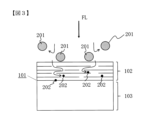
- FIG. 1 is a schematic diagram showing the state of filtration by the porous membrane of the present invention.
- FIG. 2 is a schematic diagram showing a filtration state by a conventional porous membrane.
- FIG. 3 is a schematic diagram showing a filtration state by a conventional porous membrane.
- FIG. 4 is a schematic diagram of the formation process of the porous membrane of the present invention.
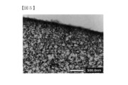
- FIG. 5 is an electron micrograph showing a cross section (part of) of a porous membrane according to one embodiment of the present invention.
- FIG. 6 is an electron micrograph showing a cross section (partial) of a conventional porous membrane.
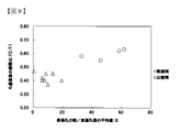
- FIG. 7 is a characteristic diagram showing the relationship between the number of surface pores and the dextran removal rate.
- FIG. 1 is a schematic diagram showing the state of filtration by the porous membrane of the present invention.
- FIG. 2 is a schematic diagram showing a filtration state by a conventional porous membrane.
- FIG. 3 is a schematic diagram showing a filtration state by a conventional
- the undiluted solution refers to the liquid to be filtered before passing through the porous membrane
- the “permeate liquid” refers to the liquid after passing through the porous membrane
- the undiluted filtration solution having a high degree of filtration difficulty refers to a liquid containing a large amount of contaminants that can clog the porous membrane in the undiluted filtration solution.
- Fouling materials are turbidity, fungi, viruses, polysaccharides, proteins, organic compounds and complexes thereof.
- Contamination substances contain coarse components (Stokes diameter: 13 nm or more) to be removed and fine components (molecular weight: 10,000 Da or less) that are preferably permeated by useful substances. many. Fine components should permeate through the porous membrane, but because they are fine, they are likely to be captured by the porous membrane and cause clogging.
- the porous membrane of the present invention exhibits high stain resistance to both coarse components and fine components in the undiluted filtrate.
- staining means that the porous membrane is clogged with coarse components (Stokes diameter: 13 nm or more) and fine components (molecular weight: 10,000 Da or less) contained in the undiluted solution in the filtration process. show. If the porous membrane is clogged with coarse components or fine components, the filtration resistance increases and the amount of liquid that can permeate the porous membrane decreases.
- a fluid such as permeate or compressed air is passed from the direction of the permeate to the direction of the filtrate, that is, in the opposite direction to the filtration.
- Back pressure washing is performed to remove coarse components captured by the porous membrane.
- Backpressure washing can easily remove coarse components that tend to accumulate outside the porous membrane, but it is difficult to remove fine components that tend to accumulate inside the porous membrane.
- the improvement in "fouling resistance" of the present invention makes it difficult for the pores of the porous membrane to become clogged regardless of whether the undiluted solution contains coarse components or fine components. .
- the porous membrane with improved stain resistance of the present invention will be described below.
- the surface portion from the surface to a thickness of 10 ⁇ m is denser than the inside, and the dextran removal rate T is 60 to 95% with a weight average molecular weight of 40,000 Da.
- the number of surface holes in the surface portion is required to be 200/ ⁇ m 2 to 2000/ ⁇ m 2 .
- a surface pore is a pore observed on the surface of the surface portion.
- the fine pores of the surface portion 102 are dense, the coarse dirt components 201 cannot penetrate into the porous membrane and do not clog the surface portion 102 of the porous membrane. It's getting harder.
- the surface portion 102 has a large number of pores, the fine contaminant components 202 enter the inside 103 from the surface portion 102 of the porous membrane in the filtration direction while being dispersed, and the porous membrane becomes difficult to stain.
- the surface portion from the surface to a thickness of 10 ⁇ m is denser than the inside, it prevents coarse contaminants and substances to be removed in the undiluted filtration solution from entering the porous membrane, and exhibits high stain resistance. .
- the fact that the surface part is more dense than the inside can be confirmed by observing the cross section of the porous membrane with a scanning electron microscope (hereinafter referred to as "SEM") at every 10 ⁇ m thick area, and the porosity of the surface part from the surface to the thickness of 10 ⁇ m is , the porosity is lower than the porosity of the inside with a thickness of 10 ⁇ m or more from the surface.
- SEM scanning electron microscope
- the image obtained by observing the cross section of the porous membrane with the SEM is binarized using the free software "ImageJ".
- Percentile in Threshold threshold for binarization
- the area of the pore portion is obtained, and the porosity is calculated by dividing it by the area of the observed porous membrane.
- the porosity of the surface portion may be smaller than that of the inside, but is preferably 55 to 90%, more preferably 63 to 80%.
- the surface is denser than the inside makes it possible to efficiently remove large dirt components and objects to be removed that are retained on the outside of the surface, especially when performing a back pressure washing process in which filtration is performed in the reverse direction during filtration. It can be discharged from the porous membrane in a short period of time, which is preferable.
- coarse contaminants and substances to be removed held on the surface can be efficiently removed from the porous membrane. It can be discharged, which is preferable.
- the inventors made it difficult for coarse components (Stokes diameter: 13 nm or more) to be removed to enter into the porous membrane, and removed coarse components that slightly entered the porous membrane by back pressure washing or the like. It was found that the removal rate of dextran having a weight-average molecular weight of 40,000 Da: T must be 60% or more in order to effectively remove the dextran from the porous membrane. By stipulating the removal rate of dextran with a specific molecular weight, it is difficult for contaminants to enter the surface, and it is possible to efficiently remove contaminants from the porous membrane by back pressure washing, etc., resulting in excellent stain resistance. A porous membrane can be obtained.
- Dextran removal rate T is preferably 68% or more, more preferably 70% or more.
- the dextran removal rate: T is 95% or less, so that fine components (molecular weight: 10,000 Da or less) that are not to be removed but are preferably permeated are not trapped in the porous membrane and are sufficiently permeated. It has been found that it exhibits high stain resistance. Further, when the dextran removal rate: T is 95% or less, the permeation resistance of the porous membrane tends to be small, and a high filtrate volume is exhibited.
- Dextran removal rate: T is more preferably 90% or less, particularly preferably 85% or less.
- Dextran removal rate with a weight average molecular weight of 40,000 Da T of 60 to 95% sufficiently prevents large fouling substances and substances to be removed in the undiluted filtration solution from entering the membrane, resulting in excellent fouling resistance. show gender.
- Dextran removal rate: T is preferably 68-90%, more preferably 70-90%, most preferably 70-85%.
- T is a cross flow linear velocity of 1.0 m/sec to the porous membrane using a dextran aqueous solution prepared so that the commercially available dextran having a weight average molecular weight of 40,000 Da is 1000 ppm and 25 ° C. It can be calculated by the following formula (3) after filtering at a transmembrane pressure difference of 10 kPa.
- T ⁇ (refractive index of undiluted solution) ⁇ (refractive index of permeated liquid) ⁇ /(refractive index of undiluted solution) ⁇ 100 Equation (3)
- the cross-flow linear velocity is a value obtained by dividing the flow rate of the undiluted solution in the direction perpendicular to the filtration direction by the cross-sectional area of the flow channel.
- the transmembrane pressure difference is the difference between the pressure on the filtrate side and the pressure on the permeated liquid side across the porous membrane.
- the fouling components in the undiluted filtration solution can be dispersed within the porous membrane. , showing excellent stain resistance. Furthermore, even if the surface pores are partially clogged by the contaminant components in the undiluted filtrate as the filtration progresses, the number of surface pores is large, so the undiluted filtration solution can pass through the porous membrane in a sufficient number of channels. , easy to show excellent stain resistance. If the number of surface pores is 200/ ⁇ m 2 or more, it is possible to sufficiently secure the flow path until washing such as back pressure washing is performed even if the undiluted filtrate is easily contaminated.
- the filtered water has a high frequency of reaching the pores on the surface of the porous membrane and tends to flow straight into the porous membrane.
- the number of surface pores of the porous membrane is more preferably 290/ ⁇ m 2 to 1500/ ⁇ m 2 , particularly preferably 350/ ⁇ m 2 to 1000/ ⁇ m 2 .
- the number of surface pores of the porous membrane is the number of pores present in the plane when the surface of the porous membrane is observed.
- an image obtained by observing the surface of the porous membrane with an SEM is binarized using free software "ImageJ".
- RenyiEntropy is selected in Threshold (threshold for binarization).
- Threshold threshold for binarization
- the number of holes in the range observed by Analyze Particles is obtained.
- the number of surface pores per unit area [number/ ⁇ m 2 ] 1,000 or more pores are observed, and the number of pores is divided by the total area of the observed region.
- FIG. 7 is a characteristic diagram showing the relationship between the number of surface pores and the dextran removal rate.
- the porous membrane of the prior art is a comparative example in FIG. It tends to be less, and there is a trade-off relationship.
- the porous membrane of the present invention is an example in FIG. 7, indicated by a circle mark, and it can be seen that the number of surface pores is 200/ ⁇ m 2 or more and the dextran removal rate is 60% or more. .
- the porous membrane of the present invention overcomes the trade-offs of the prior art, and has both a large number of surface pores and a high dextran removal rate, thereby exhibiting excellent stain resistance. be able to.
- the surface pore diameter is the diameter of the in-plane pores when observing the surface of the porous membrane.
- an image obtained by observing the surface of the porous membrane with an SEM is binarized using free software "ImageJ".
- RenyiEntropy in Threshold threshold for binarization.
- the area of each pore is obtained, and the diameter calculated assuming each pore to be a circle is taken as the surface pore diameter.
- the average surface pore diameter the pore diameters of 1,000 or more pores are averaged.
- the inventors have found that the small pores prevent coarse contaminant components and objects to be removed from entering the porous membrane, and the large number of pores It was found that a sufficient number of channels for the undiluted filtration to permeate the porous membrane can be ensured, and the fouling components can be dispersed, so that excellent fouling resistance is likely to be exhibited.
- stain resistance it is preferable from the viewpoint of stain resistance to achieve both a good (small) surface pore size and a good (large) number of surface pores.
- Both the number of surface pores and the surface pore diameter satisfy a positive correlation, and both contribute to stain resistance.
- the number of surface pores has a negative correlation with the diameter of the surface pores, it is preferable to use the X value divided by the diameter of the surface pores as an index rather than using only the number of surface pores as an index.
- the porous membrane of the present invention is formed by making the self-diffusion coefficient of the polymer relatively small, that is, making it difficult to move, in the process of forming the porous membrane, thereby preventing excessive phase separation and coarsening. It is easy to overcome the trade-off between the pore size and the number of pores by suppressing the pore size and solidifying in a state where fine pores exist in large numbers.
- X is 30 to 100/ ⁇ m 2 /nm, which is higher than the normal trade-off relationship, it is preferable for exhibiting excellent stain resistance, and 32 to 80/ ⁇ m 2 /nm is more preferable. , 50 to 70/ ⁇ m 2 /nm.
- R is 1.0 to 8.0
- fine dirt components in the undiluted filtrate can permeate the porous membrane without clogging, and the porous membrane has excellent stain resistance. It is easy to show the nature and is preferable.
- the tortuosity is also called tortuosity, and means the degree to which the channel through which the undiluted filtrate passes is tortuous. In other words, the lower the tortuous path ratio, the closer the flow path is to a straight line, and the dirt component passes through the short flow path, so clogging in the porous membrane is less likely to occur.
- FIG. 3 is a schematic diagram showing a filtration state by a conventional porous membrane.
- the tortuous road ratio: R is obtained using the following formula (1).
- R ( ⁇ /2k) 1/2 V/S Expression (1)
- ⁇ porosity
- k permeability coefficient [m 2 ]
- V pore specific volume [m 3 /g]
- S specific surface area [m 2 /g]
- k Permeability coefficient is a coefficient calculated by Equation (2) from Q [cm 3 /sec] of pure water permeation rate: Q [cm 3 /sec] of membrane area: A [m 2 ] at 25 ° C. and pressure: P [Pa] and
- the porosity: ⁇ can be determined by observing the surface region from the surface to a thickness of 10 ⁇ m with an SEM and analyzing the binarized image of the cross section of the porous membrane, as described above.
- the specific surface area: S and the pore specific volume: V can be measured by the BET method using a generally commercially available nitrogen adsorption measuring device.
- the permeability coefficient: k [m 2 ] in the formula (1) of the tortuous path ratio R is 0.5 ⁇ 10 ⁇ 17 m 2 to 5.0 ⁇ 10 ⁇ 17 m 2 . It is preferable from the viewpoint that good characteristics of are obtained stably.
- the surface of the porous membrane is collected with a commercially available freezing microtome and used as the porous membrane sample for nitrogen adsorption measurement.
- the blade can be brought into contact with the porous membrane to cut it.
- the blade is oriented parallel to the surface of the porous membrane.
- the porous membrane is cut once by moving closer to the blade at intervals of 0.5 ⁇ m. Thereafter, by setting the moving distance to 10 ⁇ m and cutting once more, a surface portion having a thickness of 10 to 10.5 ⁇ m can be obtained from the surface.
- the average value of the cross-sectional pore diameter [nm] in the cross section of the outermost surface portion is 1 nm to 99 nm, and the number of cross-sectional pores is 100/
- a cross-sectional hole means a hole observed in the cross section of the outermost surface portion.
- the average value of cross-sectional pore diameters [nm] in the cross section of the outermost surface is as fine as 1 nm to 99 nm, coarse dirt components and substances to be removed in the undiluted filtration solution are captured on the outermost surface of the porous membrane. Easy to prevent intrusion. Furthermore, since the number of cross-sectional holes is as large as 100/ ⁇ m 2 to 1000/ ⁇ m 2 , the holes are formed vertically, horizontally, and in all directions, and the flow paths are easily connected in a straight line. Clogging is less likely to occur when dirt components permeate the porous membrane. In addition, even when some of the pores are clogged, the flow paths for the undiluted filtration solution to permeate the porous membrane can be ensured.
- the surface portion 102 of the porous membrane has a dense structure, has many pores, and the pores extending three-dimensionally are connected vertically and horizontally.
- the pore size is smaller than 0.1 ⁇ m, and the number of pores forms an ultra-dense nano-network structure.
- Fine contaminant components 202 pass through any one of the plurality of connected holes without being captured by the resin portion of the network structure.
- the size of the pores of the porous membrane is adjusted according to the size of the fine components. Since 202 is less likely to be trapped in the mesh, the larger the number of pores, the better, which is preferable from the viewpoint of improving stain resistance and good permeability.
- porous membranes have a large number of pores, that is, they exist densely, the lower the tortuosity, the shorter the shortest distance formed by a number of pores. Since a channel can be secured by another fine pore, the change in the tortuosity ratio corresponding to the shortest distance is small, and the permeability can be easily maintained, which is preferable.
- the nano-network structure of the present invention is characterized in that the pore size is fine and the number of pores is large as compared with general network structures.
- a typical network structure has a large pore size and a small number of pores.
- the network structure shown in the drawings of Patent Document 1 has a pore size of 1 to 2 ⁇ m and the number of pores is 0.1/ ⁇ m 2 or less, and the pore size of the network structure of the example of Patent Document 2 is small. is 300 nm, and the number of pores is about 10/ ⁇ m 2 .
- the polymer resin part forms a network, and each pore in the network is very small as described above, and the pores are numerous and dense.
- FIG. 2 shows a schematic diagram of filtration of a stock solution, which is highly difficult to filter, with such a porous membrane.
- coarse contaminant components 201 are difficult to be blocked by the surface layer 102, enter the porous membrane and stay there, and easily cause clogging. Further, the fine dirt component 202 has a large pore size and is likely to be caught in a network structure with a high tortuosity. Compare with Figure 1. Coarse contaminant components 201 and fine contaminant components 202 contaminate the porous membrane, making it difficult to maintain filtration performance over a long period of time.
- the average cross-sectional pore size is more preferably 1.0 nm to 38 nm, particularly preferably 1.0 to 36 nm.
- the number of cross-sectional pores is more preferably 120 to 800/ ⁇ m 2 , particularly preferably 140 to 600/ ⁇ m 2 .
- the area of each hole is obtained, and the diameter calculated assuming each hole as a circle is taken as the cross-sectional hole diameter.
- the average value of cross-sectional pore diameters the pore diameters of 1,000 or more pores are averaged.
- the number of cross-sectional holes is divided by the total area of the analyzed image to obtain the number of holes per unit area. Similar to the pore diameter, it is calculated by analyzing an image containing 1,000 or more pores.
- the inventors found that even in the cross section of the outermost surface, the cross-sectional pores are small, so that coarse dirt components and substances to be removed in the undiluted filtration solution are prevented from entering the porous membrane.
- the large number of cross-sectional pores ensures a sufficient number of flow paths for the undiluted filtration solution to permeate the porous membrane, and the fouling components can be dispersed, thereby easily exhibiting excellent fouling resistance. Since the cross-sectional pore number and the cross-sectional pore size are correlated and both contribute to the stain resistance, it is preferable to use the Y value, which takes into consideration both, as an index of the stain resistance.
- the porous membrane of the present invention exhibits excellent stain resistance when Y is 3 to 10/ ⁇ m 2 /nm, which is higher than the usual trade-off relationship . /nm, and particularly preferably 5 to 10/ ⁇ m 2 /nm.
- the standard deviation of the cross-sectional pore diameter [nm] is 1.0 nm to 50 nm, so that the load of fouling substances on the porous membrane can be made uniform, and excellent fouling resistance is achieved. is easy to show, which is preferable. More preferably, the standard deviation of the cross-sectional pore size is 1.0 nm to 35 nm.
- the standard deviation of the cross-sectional pore size can be calculated by obtaining the data of each cross-sectional pore size by binarizing and analyzing the TEM image obtained by observing the cross section of the porous membrane as described above.
- the standard deviation of the surface pore diameter [nm] of the surface portion of the porous membrane is 0.5 to 5.0 nm, the load of fouling substances on the porous membrane can be made uniform, resulting in excellent fouling resistance. is easy to show, which is preferable.
- the smaller the standard deviation of the surface pore diameter the smaller the variation in pore diameter.
- the standard deviation of the surface pore diameter can be calculated by obtaining data on each surface pore diameter by binarizing and analyzing the SEM image obtained by observing the surface of the porous membrane as described above.
- the porous membrane of the present invention comprises step (A): dissolving a polymer in a solvent to obtain a polymer solution, and then step (B): solidifying the polymer solution in a non-solvent to form a porous membrane.
- a self-diffusion coefficient [m 2 /sec ] is 0.8 ⁇ 10 ⁇ 11 m 2 /sec to 1.6 ⁇ 10 ⁇ 11 m 2 /sec
- the non-solvent used in step (B) contains 90 to 100% by weight of water
- the non-solvent can be obtained by a production method in which the temperature of is 6°C to 45°C.
- the type of polymer used in step (A) is not particularly limited, but specific examples include polysulfone-based resins, polyethersulfone-based resins, polyvinylidene fluoride-based resins, nylon, cellulose acetate, cellulose acetate propionate, and the like.
- the membrane contains polyvinylidene fluoride resin, which has excellent chemical resistance.
- a polyvinylidene fluoride resin refers to a vinylidene fluoride homopolymer or a vinylidene fluoride copolymer.
- the vinylidene fluoride copolymer refers to a polymer having a vinylidene fluoride residue structure.
- a polymer having a vinylidene fluoride residue structure is typically a copolymer of a vinylidene fluoride monomer and other fluorine-based monomers.
- fluoromonomers examples include vinyl fluoride, ethylene tetrafluoride, propylene hexafluoride, and ethylene trifluoride chloride.
- ethylene or the like other than the fluorine-based monomer may be copolymerized to the extent that the effects of the present invention are not impaired.
- the polyvinylidene fluoride-based resin is more preferably contained in an amount of 50% by weight or more, particularly preferably 60% by weight or more. It is preferable that the weight average molecular weight of the polymer is 5 to 1,000,000 Da because the self-diffusion coefficient described later can be easily controlled within a relatively slow and suitable range. Moreover, you may use polymer
- the solvent preferably contains a good solvent.
- the term "good solvent” refers to a solvent capable of dissolving 5% by weight or more of a polymer even in a low temperature range of 60°C or less.
- Good solvents include, for example, N-methyl-2-pyrrolidone (hereinafter “NMP”), 2-pyrrolidone (hereinafter “2P”), ⁇ -caprolactam (hereinafter “ ⁇ -CL”), dimethylacetamide, dimethyl formamide, methyl ethyl ketone, acetone, tetrahydrofuran, tetramethyl urea, trimethyl phosphate, or a mixed solvent thereof. It is more preferable that the good solvent is contained in the solvent in an amount of 40% by weight or more, particularly preferably 60% by weight or more.
- non-solvents include water, hexane, pentane, benzene, toluene, methanol, ethanol, carbon tetrachloride, o-dichlorobenzene, trichloroethylene, ethylene glycol, diethylene glycol, triethylene glycol, propylene glycol, butylene glycol, pentane.
- the concentration (% by weight) of the polymer in the polymer solution is preferably equal to or higher than the entanglement concentration in order to control the self-diffusion coefficient within a suitable range, more specifically, preferably 10 to 40% by weight. 12 to 30% by weight is more preferred, and 15 to 25% by weight is particularly preferred. It was found that a polymer concentration of 10% by weight or more can make the self-diffusion coefficient relatively slow, and that the porous membrane can be coagulated with a large number of fine pores.
- the polymer concentration is more preferably 12% by weight or more, particularly preferably 15% by weight or more. Further, by setting the concentration of the polymer to 40% by weight or less, the proportion of the polymer in the porous membrane can be reduced, and a sufficient number of pores can be secured.
- the polymer concentration is more preferably 30% by weight or less, particularly preferably 25% by weight or less.
- FIG. 4 is a schematic diagram showing the process of forming a porous membrane in step (B).
- Phase separation progresses in the polymer solution in order from (a) to (f) in FIG. 4, and the portion with a high polymer concentration (the phase 301 containing a large amount of polymer) coarsens.
- the phase 301 containing a large amount of polymer coarsens.
- exchange between the solvent and the non-solvent progresses, and when the concentration of the non-solvent rises above a certain level, the polymer solidifies and the structure of the porous membrane is fixed.
- the phase 302 containing a large amount of solvent becomes the pores of the porous membrane.
- the self-diffusion coefficient of the polymer is set to a relatively low range of 0.8 ⁇ 10 ⁇ 11 m 2 /sec to 1.6.
- the self-diffusion coefficient is 0.8 ⁇ 10 ⁇ 11 m 2 /sec or more, the diffusion coefficient is sufficient for phase separation between the polymer and the solvent, and pores are easily formed.
- Pores are less likely to form when diffusion of the polymer is slow enough to cause phase separation.
- the self-diffusion coefficient is 1.6 ⁇ 10 ⁇ 11 m 2 /sec or less, excessive phase separation and coarsening are suppressed, coalescence of pores is suppressed, and many fine pores are easily formed. . That is, by appropriately controlling the self-diffusion coefficient of the polymer within a relatively low range, a porous membrane having many fine pores can be formed.
- the self-diffusion coefficient is more preferably 0.8 ⁇ 10 ⁇ 11 m 2 /sec to 1.4 ⁇ 10 ⁇ 11 m 2 /sec, more preferably 0.8 ⁇ 10 ⁇ 11 m 2 / sec to 1.1 ⁇ More preferably, it is 10 ⁇ 11 m 2 /sec.
- the non-solvent used for solidification contains 90 to 100% by weight of water, so that solidification is rapid, and the self-diffusion coefficient in the polymer solution affects the speed of phase separation and coarsening. Easy to give. That is, it is easy to obtain the effect of controlling the self-diffusion coefficient in the polymer solution to a relatively low range.
- the temperature of the non-solvent is 6° C. to 45° C., solidification is rapid, and the self-diffusion coefficient in the polymer solution tends to affect the speed of phase separation and coarsening.
- the temperature of the non-solvent is more preferably 10°C to 35°C, more preferably 15°C to 30°C.
- Hydrogen bond donor and hydrogen bond acceptor solvents are not particularly limited, but specific examples include 2P, ⁇ -CL, 1,3-dimethylurea, N-methylacetamide, hydantoin, 2-imidazolidinone, DL - includes pyroglutamic acid and the like.
- the polymer to be dissolved contains a polymer having hydrogen bond donor and/or hydrogen bond acceptor properties, so that the self-diffusion coefficient of the polymer can be easily controlled within an appropriate range, which is preferable.
- the polymer has hydrogen bond donor and/or hydrogen bond acceptor properties, so that it interacts with a solvent having hydrogen bond donor and hydrogen bond acceptor properties through hydrogen bonding, and the self-diffusion coefficient of the polymer is relatively slow. This is because it is easy to control within a suitable range.
- the polymer having hydrogen bond donor and/or hydrogen bond acceptor properties should be contained in the porous membrane in an amount of 10% to 50% by weight. more preferred.
- the number of moles of the hydrogen-bond-donating functional groups contained in the solvent in step (A) above is the number of moles of the hydrogen-bond-donating functional groups contained in the polymer having hydrogen-bond-donating and/or hydrogen-bond-accepting properties.
- the divided value is 1.0 to 12
- the hydrogen bond between the polymer and the solvent is in an appropriate range, and the self-diffusion coefficient of the polymer is relatively slow and easy to control within an appropriate range.
- the numerical value is more preferably 2.0 to 9.0, particularly preferably 5.4 to 8.0.
- the porous membrane of the present invention may further comprise other layers.
- the porous membrane of the present invention is preferably arranged on the surface.
- the above-mentioned other layer is not particularly limited as long as it is a constituent element capable of overlapping with the porous membrane to form a layered structure, but the above-mentioned other layer is preferably a support.
- the term "support” refers to a structure that physically reinforces the porous membrane and has higher breaking strength than the porous membrane.
- a section of the obtained surface portion was measured by the BET method using a commercially available nitrogen adsorption measurement device (manufactured by Microtrack Bell; BELSORP-miniII) to determine the pore specific volume: V [m 3 /g] and the specific surface area S [m 2 /g] was measured.
- the area of each surface pore was obtained, and the diameter calculated on the assumption that each surface pore was a circle was taken as the surface pore diameter.
- the surface pore diameters of 1000 or more pores were averaged.
- the standard deviation was obtained from the data of each surface pore size. The number of surface pores was divided by the total area of the observed region to obtain the number of surface pores per unit area.
- a cross section of the outermost surface of the porous membrane was observed with a TEM (manufactured by JEOL Ltd.; JEM-1400Plus), an image was obtained, and binarized using free software "ImageJ".
- Minimum was selected for Threshold (threshold for binarization).
- Area in Analyze Particles the area of each cross-sectional pore was obtained, and the diameter calculated assuming each cross-sectional pore to be a circle was taken as the cross-sectional pore diameter.
- the cross-sectional pore diameters of 1,000 or more cross-sectional pores are averaged.
- the number of cross-sectional holes per unit area was obtained by dividing the number of cross-sectional holes by the total area of the analyzed region.
- the surface pore diameter is calculated by analyzing an image containing 1,000 or more pores.
- the standard deviation was obtained from the data of each cross-sectional pore size.
- the average value of the cross-sectional pore diameter [nm] in the cross section of the outermost surface portion is 1 nm to 99 nm, and the number of cross-sectional pores is 100/
- a network structure of ⁇ m 2 to 1000/ ⁇ m 2 was determined to have a nano-network structure.
- Self-diffusion coefficients of polymers were determined by all-atom molecular dynamics calculations.
- a polymer solution system was prepared so as to have the polymer concentration (% by weight) actually used.
- one model polymer chain was modeled to have a molecular weight of 800 to 6000 and 1/200 to 1/5 of the weight average molecular weight of the polymer actually used.
- GAFF2 was used as the potential parameter used in the molecular dynamics calculation.
- a constant pressure-temperature ensemble was constructed by controlling the temperature at 25° C. and the pressure at 1 bar.
- the short-range Lennard-Johns interaction was handled by applying a switch function from 1.0 nm and cutting off at 1.2 nm, and the long-range electrostatic interaction was calculated by the Particle Mesh Ewald method.
- the unit cell length was adjusted so as to obtain an average density, and an additional calculation of 11 ns was performed with a constant temperature ensemble.
- the mean square displacement (MSD) of each atom of the polymer was obtained, and the self-diffusion coefficient was calculated from the following formula (4).
- the value obtained by dividing log(MSD) by log(t) was in the range of 0.9 to 1.1 for the range of MSD and t used to calculate D.
- the weighted average value of the self-diffusion coefficient of each polymer based on the weight percentage of the polymer is taken as the self-diffusion coefficient of the polymer in the polymer solution. bottom.
- Example 1 A hollow fiber porous membrane containing a support obtained by the following method was used as the porous membrane. 38% by mass of PVDF (Kureha; KF1300, weight average molecular weight: 350,000 Da) and 62% by mass of ⁇ -butyrolactone were mixed and dissolved at 160° C. to prepare a stock solution of the support membrane.
- This support membrane undiluted solution was discharged from a double-tube nozzle while being accompanied by an aqueous 85 mass % ⁇ -butyrolactone solution as a cavity-forming liquid.
- the discharged support membrane undiluted solution was solidified in a cooling bath containing an 85% by mass ⁇ -butyrolactone aqueous solution at a temperature of 20° C. placed 30 mm below the spinneret to prepare a hollow fiber support having a spherical structure.
- PVDF1 manufactured by Arkema; “Kynar” (registered trademark) 710, weight average molecular weight of 180,000 Da
- cellulose diacetate manufactured by Eastman; CA-398-3
- cellulose triacetate manufactured by Eastman; CA-436-80S
- NMP 68.8% by mass of NMP
- 2P 12% by mass of 2P
- the polymer solution was uniformly applied to the outer surface of the hollow fiber support at 10 m/min (thickness: 50 ⁇ m).
- the support coated with the polymer solution is taken up at 10 m/min, and after 1 second from the coating, it is passed through a coagulation bath of distilled water at 25° C. for 10 seconds so as to be immersed and solidified, resulting in a porous membrane having a three-dimensional network structure. formed.
- Table 1 shows the evaluation results of the obtained porous membrane.
- the surface portion of the porous membrane from the surface to a thickness of 10 ⁇ m was denser than the inside.
- FIG. 5 shows a TEM image of the cross section of the outermost surface of the porous membrane.
- Example 2 A porous membrane was obtained in the same manner as in Example 1, except that 2P in the polymer solution was changed to ⁇ -CL.
- Table 1 shows the evaluation results of the porous membrane.
- the surface portion of the porous membrane from the surface to a thickness of 10 ⁇ m was denser than the inside.
- the resulting porous membrane had a tortuosity R of 4.1, a dextran removal rate of T of 65%, and the number of surface pores: 291/ ⁇ m 2 .
- the number of surface pores was divided by the average surface pore diameter. Value: X was good at 33/ ⁇ m 2 /nm.
- the filtration flux ratio (F2/F1) was 0.58, and the filtration flux could be maintained even after long-term use.
- Example 3 A porous membrane was obtained in the same manner as in Example 1 except that the composition ratio of the polymer solution was changed as shown in Table 1.
- Table 1 shows the evaluation results of the porous membrane.
- the surface portion of the porous membrane from the surface to a thickness of 10 ⁇ m was denser than the inside.
- the tortuosity of the obtained porous membrane R: 5.9, Dextran removal rate: T: 72%, Number of surface pores: 329/ ⁇ m 2 , The number of surface pores was divided by the average surface pore diameter. Value: X was good at 46/ ⁇ m 2 /nm.
- the filtration flux ratio (F2/F1) was 0.55, and the filtration flux could be maintained even after long-term use.
- Example 4 A porous membrane was obtained in the same manner as in Example 1 except that the composition ratio of the polymer solution was changed as shown in Table 1.
- the porous membrane had a nano-network structure.
- Table 1 shows the evaluation results of the porous membrane.
- the surface portion of the porous membrane from the surface to a thickness of 10 ⁇ m was denser than the inside.
- the tortuous path ratio of the obtained porous membrane R: 4.9, dextran removal rate: T: 69%, number of surface pores: 420/ ⁇ m 2 , the number of surface pores was divided by the average surface pore diameter.
- Value: X was good at 58/ ⁇ m 2 /nm.
- the filtration flux ratio (F2/F1) was 0.62, and the filtration flux could be maintained even after long-term use.
- Example 5 (Example 5) (ix) Filterability of the porous membrane was evaluated using the filtration evaluation method for aqueous gelatin solution.
- the porous membrane was used to represent Example 1. When the aqueous gelatin solution was filtered, the removal rate of gelatin was 65% for T gelatin , and the filtration flux was good at 70 L/m 2 /h.
- Table 3 shows the filtration evaluation results of the gelatin solution.
- the tortuous path ratio of the porous membrane used for evaluation: R is 4.9, the dextran removal rate is 72%, the number of surface pores is 444/ ⁇ m 2 , and the number of surface pores is the average value of the surface pore diameter. Value divided by: X was 62/ ⁇ m 2 /nm.
- Example 6 Filterability of the porous membrane was evaluated using the apple juice filtration evaluation method.
- the porous membrane was used to represent Example 1.
- the removal rate of apple juice was 99.9% for T apple
- the filtration flux was 37 L/m 2 /h, which was good.
- Table 4 shows the filtration evaluation results of the apple juice.
- the tortuous path ratio of the porous membrane used for evaluation: R is 4.9
- the dextran removal rate is 72%
- the number of surface pores is 444/ ⁇ m 2
- the number of surface pores is the average value of the surface pore diameter. Value divided by: X was 62/ ⁇ m 2 /nm.
- Comparative example 2 In the film formation of Comparative Example 1, PVDF1 in the polymer solution was changed to PVDF2 (manufactured by Arkema: HSV900, melt viscosity 4700 Pa s), and a porous film was formed in the same manner as in Comparative Example 1 except that the composition ratio was changed. A membrane was obtained. Table 2 shows the evaluation results of the porous membrane. The surface portion of the porous membrane from the surface to a thickness of 10 ⁇ m was denser than the inside, but the number of surface pores and the dextran removal rate: T did not satisfy the conditions. (xi) In the factory wastewater filtration evaluation method, the initial ratio (F2/F1) of the filtration flux was 0.40, and the filtration flux greatly decreased after long-term use.
- FIG. 6 shows a TEM image of the cross section of the outermost surface of the porous membrane.
- Table 2 shows the evaluation results.
- the porous membrane did not have a nano-network structure.
- the surface portion of the porous membrane from the surface to a thickness of 10 ⁇ m was denser than the inside, but the number of surface pores, tortuosity: R, and dextran removal rate: T did not satisfy the conditions.
- xi In the method for evaluating the filtration of industrial wastewater, the amount of permeated liquid was remarkably small, and it was difficult to measure the filtration flux, which was below the lower limit of measurement. It is considered that the filtration flux was extremely low because the number of surface pores was small and the dextran removal rate: T was excessive.
- Comparative Example 5 A porous membrane was obtained in the same manner as in the membrane formation of Comparative Example 3, except that the composition ratio of the polymer solution was changed.
- the composition ratio of 2P was set to 30% by mass.
- Table 2 shows the evaluation results of the porous membrane.
- the surface portion of the porous membrane from the surface to a thickness of 10 ⁇ m was denser than the inside, but the number of surface pores, tortuosity: R, and dextran removal rate: T did not satisfy the conditions.
- the initial ratio (F2/F1) of the filtration flux was 0.45, and the filtration flux greatly decreased after long-term use.
- Example 6 A porous membrane was obtained in the same manner as in Example 1, except that 2P in the polymer solution was changed to ⁇ -butyrolactone. Table 2 shows the evaluation results of the porous membrane. The surface portion of the porous membrane from the surface to a thickness of 10 ⁇ m was denser than the inside, but the average surface pore size, tortuosity: R, and dextran removal rate: T did not satisfy the conditions. (xi) In the factory wastewater filtration evaluation method, the initial ratio (F2/F1) of the filtration flux was 0.40, and the filtration flux greatly decreased after long-term use.
- the polymer solution was uniformly applied to the outer surface of the hollow fiber support at 10 m/min (thickness: 50 ⁇ m).
- the support coated with the polymer solution is taken up at 10 m/min, and after 1 second from the coating, it is passed through a coagulation bath of distilled water at 15° C. for 10 seconds so as to be immersed and solidified, resulting in a porous membrane having a three-dimensional network structure. formed.
- Table 5 shows the evaluation results of the obtained porous membrane.
- the surface portion of the porous membrane from the surface to a thickness of 10 ⁇ m was denser than the inside.
- the polymer solution was uniformly applied to the outer surface of the hollow fiber support at 10 m/min (thickness: 50 ⁇ m).
- the support coated with the polymer solution is taken up at 10 m/min, and after 1 second from coating, it is passed through a coagulation bath of distilled water at 25° C. for 30 seconds to be coagulated, resulting in a porous membrane having a three-dimensional network structure. formed.
- Table 5 shows the evaluation results of the obtained porous membrane.
- the surface portion of the porous membrane from the surface to a thickness of 10 ⁇ m was denser than the inside.
- T Dextran removal rate of the resulting porous membrane: T is 24%, number of surface pores: 2/ ⁇ m 2 , value obtained by dividing the number of surface pores by the average surface pore diameter: X is 0.01/ ⁇ m 2 /nm, and (xi) in the evaluation method for filtration of factory wastewater, the amount of permeated liquid was remarkably small, and it was difficult to measure the filtration flux, which was below the lower limit of measurement. It is considered that the filtration flux was extremely low due to the small number of surface pores and the low dextran removal rate: T.
- the polymer solution was uniformly applied to the outer surface of the hollow fiber support at 10 m/min (thickness: 50 ⁇ m).
- the support coated with the polymer solution is taken up at 10 m/min, and after 1 second from coating, it is passed through a coagulation bath of distilled water at 25° C. for 30 seconds to be coagulated, resulting in a porous membrane having a three-dimensional network structure. formed.
- Table 5 shows the evaluation results of the obtained porous membrane.
- the surface portion of the porous membrane from the surface to a thickness of 10 ⁇ m was denser than the inside.
- FIG. 10 shows the relationship between the self-diffusion coefficient and the initial filtration flux ratio (F2/F1) for the example and the comparative example. From the examples and comparative examples, the initial ratio of the filtration flux was 0.50 or more when the self-diffusion coefficient ranged from 0.8 ⁇ 10 ⁇ 11 m 2 /sec to 1.6 ⁇ 10 ⁇ 11 m 2 /sec. Good filtration performance was maintained even after long-term operation.
Landscapes
- Chemical & Material Sciences (AREA)
- Chemical Kinetics & Catalysis (AREA)
- Dispersion Chemistry (AREA)
- Engineering & Computer Science (AREA)
- Manufacturing & Machinery (AREA)
- Separation Using Semi-Permeable Membranes (AREA)
Priority Applications (6)
| Application Number | Priority Date | Filing Date | Title |
|---|---|---|---|
| US18/692,084 US20240375060A1 (en) | 2021-09-28 | 2022-09-26 | Porous membrane and method for manufacturing porous membrane |
| EP22876095.5A EP4410411A4 (en) | 2021-09-28 | 2022-09-26 | Porous membrane and method for manufacturing porous membrane |
| CN202280059145.1A CN117881468A (zh) | 2021-09-28 | 2022-09-26 | 多孔膜和制造多孔膜的方法 |
| JP2022576815A JP7586198B2 (ja) | 2021-09-28 | 2022-09-26 | 多孔質膜及び多孔質膜の製造方法 |
| KR1020247008581A KR20240087690A (ko) | 2021-09-28 | 2022-09-26 | 다공질막 및 다공질막의 제조 방법 |
| JP2024126513A JP7736137B2 (ja) | 2021-09-28 | 2024-08-02 | 多孔質膜及び多孔質膜を用いた液体のろ過方法 |
Applications Claiming Priority (2)
| Application Number | Priority Date | Filing Date | Title |
|---|---|---|---|
| JP2021-157467 | 2021-09-28 | ||
| JP2021157467 | 2021-09-28 |
Publications (1)
| Publication Number | Publication Date |
|---|---|
| WO2023054228A1 true WO2023054228A1 (ja) | 2023-04-06 |
Family
ID=85782585
Family Applications (1)
| Application Number | Title | Priority Date | Filing Date |
|---|---|---|---|
| PCT/JP2022/035592 Ceased WO2023054228A1 (ja) | 2021-09-28 | 2022-09-26 | 多孔質膜及び多孔質膜の製造方法 |
Country Status (6)
| Country | Link |
|---|---|
| US (1) | US20240375060A1 (https=) |
| EP (1) | EP4410411A4 (https=) |
| JP (2) | JP7586198B2 (https=) |
| KR (1) | KR20240087690A (https=) |
| CN (1) | CN117881468A (https=) |
| WO (1) | WO2023054228A1 (https=) |
Cited By (1)
| Publication number | Priority date | Publication date | Assignee | Title |
|---|---|---|---|---|
| WO2025225556A1 (ja) * | 2024-04-22 | 2025-10-30 | 東レ株式会社 | 複合半透膜およびその製造方法、分離膜エレメントならびに流体分離装置 |
Citations (6)
| Publication number | Priority date | Publication date | Assignee | Title |
|---|---|---|---|---|
| JPH01176407A (ja) * | 1987-12-28 | 1989-07-12 | Daicel Chem Ind Ltd | ポリスルホン製中空糸膜の製造法 |
| JP2006082006A (ja) | 2004-09-16 | 2006-03-30 | Daicel Chem Ind Ltd | フィルタ素材及びその製造方法 |
| JP2010094670A (ja) | 2008-09-19 | 2010-04-30 | Toray Ind Inc | ポリフッ化ビニリデン系複合膜およびその製造方法 |
| WO2016031834A1 (ja) * | 2014-08-25 | 2016-03-03 | 旭化成メディカル株式会社 | 多孔質膜 |
| WO2018182027A1 (ja) * | 2017-03-30 | 2018-10-04 | 東レ株式会社 | 分離膜及び分離膜の製造方法 |
| WO2020262490A1 (ja) * | 2019-06-27 | 2020-12-30 | 東レ株式会社 | 多孔質膜および複合多孔質膜 |
Family Cites Families (6)
| Publication number | Priority date | Publication date | Assignee | Title |
|---|---|---|---|---|
| JP3217842B2 (ja) * | 1992-03-03 | 2001-10-15 | 旭化成株式会社 | 中空糸状高性能精密濾過膜 |
| JP4003982B2 (ja) * | 1995-06-30 | 2007-11-07 | 東レ株式会社 | ポリスルホン系選択透過性分離膜 |
| JP5109263B2 (ja) * | 2005-02-28 | 2012-12-26 | 東レ株式会社 | フッ素樹脂系高分子分離膜およびその製造方法 |
| CN102159305B (zh) * | 2008-09-19 | 2015-08-19 | 东丽株式会社 | 分离膜及其制造方法 |
| JP6105875B2 (ja) | 2012-08-20 | 2017-03-29 | ユニチカ株式会社 | 有機溶剤耐性を有するポリアミド限外濾過膜、及びその製造方法 |
| AU2018342736A1 (en) * | 2017-09-28 | 2020-04-09 | Toray Industries, Inc. | Porous hollow fiber membrane and method for producing same |
-
2022
- 2022-09-26 CN CN202280059145.1A patent/CN117881468A/zh active Pending
- 2022-09-26 JP JP2022576815A patent/JP7586198B2/ja active Active
- 2022-09-26 WO PCT/JP2022/035592 patent/WO2023054228A1/ja not_active Ceased
- 2022-09-26 US US18/692,084 patent/US20240375060A1/en active Pending
- 2022-09-26 KR KR1020247008581A patent/KR20240087690A/ko active Pending
- 2022-09-26 EP EP22876095.5A patent/EP4410411A4/en active Pending
-
2024
- 2024-08-02 JP JP2024126513A patent/JP7736137B2/ja active Active
Patent Citations (6)
| Publication number | Priority date | Publication date | Assignee | Title |
|---|---|---|---|---|
| JPH01176407A (ja) * | 1987-12-28 | 1989-07-12 | Daicel Chem Ind Ltd | ポリスルホン製中空糸膜の製造法 |
| JP2006082006A (ja) | 2004-09-16 | 2006-03-30 | Daicel Chem Ind Ltd | フィルタ素材及びその製造方法 |
| JP2010094670A (ja) | 2008-09-19 | 2010-04-30 | Toray Ind Inc | ポリフッ化ビニリデン系複合膜およびその製造方法 |
| WO2016031834A1 (ja) * | 2014-08-25 | 2016-03-03 | 旭化成メディカル株式会社 | 多孔質膜 |
| WO2018182027A1 (ja) * | 2017-03-30 | 2018-10-04 | 東レ株式会社 | 分離膜及び分離膜の製造方法 |
| WO2020262490A1 (ja) * | 2019-06-27 | 2020-12-30 | 東レ株式会社 | 多孔質膜および複合多孔質膜 |
Non-Patent Citations (8)
| Title |
|---|
| B. R. BROOKSR. E. BRUCCOLERIB. D. OLAFSOND. J. STATESS. SWAMINATHANM. KARPLUS, J. COMPUT. CHEM, vol. 4, 1983, pages 187 |
| H. C. ANDERSEN, J. CHEM. PHYS, vol. 72, 1980, pages 2384 |
| HOOVER, W. G., PHYS. REV. A, vol. 31, 1985, pages 1695 |
| J. WANGR. M. WOLFJ. W. CALDWELLP. A. KOLLMAND. A. CASE, J. COMPUT. CHEM, vol. 25, 2004, pages 1157 |
| KOZENY-CARMAN, JOURNAL OF THE JAPANESE ASSOCIATION FOR PETROLEUM TECHNOLOGY, vol. 75, no. 2, March 2010 (2010-03-01), pages 164 - 176 |
| S. L. MAYOB. D. OLAFSONW. A. GODDARD III, J. PHYS. CHEM, vol. 94, 1990, pages 8897 |
| See also references of EP4410411A4 |
| W. L. JORGENSEND. S. MAXWELLJULIAN TIRADO-RIVES, J. AM. CHEM. SOC., vol. 118, 1996, pages 11225 |
Cited By (2)
| Publication number | Priority date | Publication date | Assignee | Title |
|---|---|---|---|---|
| WO2025225556A1 (ja) * | 2024-04-22 | 2025-10-30 | 東レ株式会社 | 複合半透膜およびその製造方法、分離膜エレメントならびに流体分離装置 |
| JP7835349B1 (ja) * | 2024-04-22 | 2026-03-25 | 東レ株式会社 | 複合半透膜およびその製造方法、分離膜エレメントならびに流体分離装置 |
Also Published As
| Publication number | Publication date |
|---|---|
| CN117881468A (zh) | 2024-04-12 |
| EP4410411A1 (en) | 2024-08-07 |
| JP7736137B2 (ja) | 2025-09-09 |
| EP4410411A4 (en) | 2025-04-30 |
| US20240375060A1 (en) | 2024-11-14 |
| KR20240087690A (ko) | 2024-06-19 |
| JP2024156859A (ja) | 2024-11-06 |
| JP7586198B2 (ja) | 2024-11-19 |
| JPWO2023054228A1 (https=) | 2023-04-06 |
Similar Documents
| Publication | Publication Date | Title |
|---|---|---|
| JP5732719B2 (ja) | 分離膜およびその製造方法 | |
| JP2007185562A (ja) | ポリフッ化ビニリデン系中空糸型微多孔膜およびその製造方法 | |
| JP2010094670A (ja) | ポリフッ化ビニリデン系複合膜およびその製造方法 | |
| WO1997022405A1 (en) | Hollow fiber type filtration membrane | |
| WO2013012024A1 (ja) | 多孔質中空糸膜 | |
| JPWO2019066061A1 (ja) | 多孔質中空糸膜及びその製造方法 | |
| JP7736137B2 (ja) | 多孔質膜及び多孔質膜を用いた液体のろ過方法 | |
| JP5778489B2 (ja) | 親水性多孔膜の製造方法、親水化剤、親水性多孔膜、及び多孔膜の親水化処理方法 | |
| JP2011036848A (ja) | ポリフッ化ビニリデン系樹脂製分離膜およびその製造方法 | |
| JP2012187575A (ja) | 複合膜及びその製造方法 | |
| JP5292890B2 (ja) | 複合中空糸膜 | |
| JPWO2009119373A1 (ja) | 中空糸膜およびその製造方法 | |
| WO2022249839A1 (ja) | 分離膜及びその製造方法 | |
| KR20090034353A (ko) | 불소 수지계 고분자 분리막 및 그의 제조 방법 | |
| JP3317975B2 (ja) | ポリアクリロニトリル系中空糸状濾過膜 | |
| JPH08108053A (ja) | 酢酸セルロース中空糸分離膜およびその製造法 | |
| JP6839766B2 (ja) | 多孔質膜を用いたろ過方法 | |
| TWI403355B (zh) | A fluororesin-based polymer separation membrane and a method for producing the same | |
| JP7552956B1 (ja) | 中空糸膜モジュールおよびろ過運転方法、ろ過装置 | |
| CN117942776A (zh) | 一种除病毒复合膜及其制备工艺 | |
| JP7697531B2 (ja) | 多孔質膜および造水方法 | |
| JPWO2016182015A1 (ja) | 多孔質中空糸膜及びその製造方法 | |
| JP2010075851A (ja) | 多孔質膜およびその製造方法 | |
| JP2004098027A (ja) | 高性能精密濾過膜 | |
| JP2006224051A (ja) | 多孔質膜、多孔質膜エレメント、および膜ろ過装置 |
Legal Events
| Date | Code | Title | Description |
|---|---|---|---|
| WWE | Wipo information: entry into national phase |
Ref document number: 2022576815 Country of ref document: JP |
|
| 121 | Ep: the epo has been informed by wipo that ep was designated in this application |
Ref document number: 22876095 Country of ref document: EP Kind code of ref document: A1 |
|
| DPE2 | Request for preliminary examination filed before expiration of 19th month from priority date (pct application filed from 20040101) | ||
| WWE | Wipo information: entry into national phase |
Ref document number: 202280059145.1 Country of ref document: CN |
|
| WWE | Wipo information: entry into national phase |
Ref document number: 18692084 Country of ref document: US |
|
| NENP | Non-entry into the national phase |
Ref country code: DE |
|
| ENP | Entry into the national phase |
Ref document number: 2022876095 Country of ref document: EP Effective date: 20240429 |