WO2023054228A1 - 多孔質膜及び多孔質膜の製造方法 - Google Patents
多孔質膜及び多孔質膜の製造方法 Download PDFInfo
- Publication number
- WO2023054228A1 WO2023054228A1 PCT/JP2022/035592 JP2022035592W WO2023054228A1 WO 2023054228 A1 WO2023054228 A1 WO 2023054228A1 JP 2022035592 W JP2022035592 W JP 2022035592W WO 2023054228 A1 WO2023054228 A1 WO 2023054228A1
- Authority
- WO
- WIPO (PCT)
- Prior art keywords
- porous membrane
- pores
- polymer
- hydrogen bond
- surface portion
- Prior art date
Links
- 239000012528 membrane Substances 0.000 title claims abstract description 322
- 238000004519 manufacturing process Methods 0.000 title claims description 15
- 238000000034 method Methods 0.000 title description 18
- 239000011148 porous material Substances 0.000 claims abstract description 236
- 238000001914 filtration Methods 0.000 claims abstract description 114
- 229920002307 Dextran Polymers 0.000 claims abstract description 46
- 239000007788 liquid Substances 0.000 claims abstract description 34
- 229920000642 polymer Polymers 0.000 claims description 117
- 239000002904 solvent Substances 0.000 claims description 58
- 239000001257 hydrogen Substances 0.000 claims description 52
- 229910052739 hydrogen Inorganic materials 0.000 claims description 52
- 238000009792 diffusion process Methods 0.000 claims description 39
- XLYOFNOQVPJJNP-UHFFFAOYSA-N water Substances O XLYOFNOQVPJJNP-UHFFFAOYSA-N 0.000 claims description 23
- 230000035699 permeability Effects 0.000 claims description 17
- 125000000524 functional group Chemical group 0.000 claims description 12
- 238000004364 calculation method Methods 0.000 claims description 10
- 238000000329 molecular dynamics simulation Methods 0.000 claims description 8
- 230000005540 biological transmission Effects 0.000 claims description 3
- 239000000356 contaminant Substances 0.000 abstract description 16
- 241000700605 Viruses Species 0.000 abstract description 4
- 238000011109 contamination Methods 0.000 abstract description 4
- 239000000243 solution Substances 0.000 description 90
- 230000004907 flux Effects 0.000 description 45
- 238000011156 evaluation Methods 0.000 description 40
- 230000000052 comparative effect Effects 0.000 description 24
- 239000000126 substance Substances 0.000 description 22
- 108010010803 Gelatin Proteins 0.000 description 18
- 229920000159 gelatin Polymers 0.000 description 18
- 239000008273 gelatin Substances 0.000 description 18
- 235000019322 gelatine Nutrition 0.000 description 18
- 235000011852 gelatine desserts Nutrition 0.000 description 18
- 230000007774 longterm Effects 0.000 description 15
- SECXISVLQFMRJM-UHFFFAOYSA-N N-Methylpyrrolidone Chemical compound CN1CCCC1=O SECXISVLQFMRJM-UHFFFAOYSA-N 0.000 description 14
- 238000010586 diagram Methods 0.000 description 14
- 239000012466 permeate Substances 0.000 description 13
- 235000015197 apple juice Nutrition 0.000 description 11
- 239000000706 filtrate Substances 0.000 description 10
- 238000005191 phase separation Methods 0.000 description 10
- 239000002245 particle Substances 0.000 description 9
- YEJRWHAVMIAJKC-UHFFFAOYSA-N 4-Butyrolactone Chemical compound O=C1CCCO1 YEJRWHAVMIAJKC-UHFFFAOYSA-N 0.000 description 8
- 239000012153 distilled water Substances 0.000 description 8
- 239000007864 aqueous solution Substances 0.000 description 7
- 230000003247 decreasing effect Effects 0.000 description 7
- 239000012510 hollow fiber Substances 0.000 description 7
- 239000000203 mixture Substances 0.000 description 7
- 229920005989 resin Polymers 0.000 description 7
- 239000011347 resin Substances 0.000 description 7
- 238000005406 washing Methods 0.000 description 7
- BQCIDUSAKPWEOX-UHFFFAOYSA-N 1,1-Difluoroethene Chemical compound FC(F)=C BQCIDUSAKPWEOX-UHFFFAOYSA-N 0.000 description 6
- 238000007710 freezing Methods 0.000 description 6
- 230000008014 freezing Effects 0.000 description 6
- 230000008569 process Effects 0.000 description 6
- 239000002351 wastewater Substances 0.000 description 6
- 238000004075 wastewater filtration Methods 0.000 description 6
- 239000002033 PVDF binder Substances 0.000 description 5
- 238000005345 coagulation Methods 0.000 description 5
- 230000015271 coagulation Effects 0.000 description 5
- 230000001276 controlling effect Effects 0.000 description 5
- 229920001577 copolymer Polymers 0.000 description 5
- 239000010410 layer Substances 0.000 description 5
- 229920001223 polyethylene glycol Polymers 0.000 description 5
- 229920002981 polyvinylidene fluoride Polymers 0.000 description 5
- 229920000036 polyvinylpyrrolidone Polymers 0.000 description 5
- 235000013855 polyvinylpyrrolidone Nutrition 0.000 description 5
- OFBQJSOFQDEBGM-UHFFFAOYSA-N Pentane Chemical compound CCCCC OFBQJSOFQDEBGM-UHFFFAOYSA-N 0.000 description 4
- 125000004429 atom Chemical group 0.000 description 4
- 230000015572 biosynthetic process Effects 0.000 description 4
- 239000011248 coating agent Substances 0.000 description 4
- 238000000576 coating method Methods 0.000 description 4
- 238000005520 cutting process Methods 0.000 description 4
- 230000001747 exhibiting effect Effects 0.000 description 4
- 230000033001 locomotion Effects 0.000 description 4
- 238000005259 measurement Methods 0.000 description 4
- ZWEHNKRNPOVVGH-UHFFFAOYSA-N 2-Butanone Chemical compound CCC(C)=O ZWEHNKRNPOVVGH-UHFFFAOYSA-N 0.000 description 3
- CSCPPACGZOOCGX-UHFFFAOYSA-N Acetone Chemical compound CC(C)=O CSCPPACGZOOCGX-UHFFFAOYSA-N 0.000 description 3
- UHOVQNZJYSORNB-UHFFFAOYSA-N Benzene Chemical compound C1=CC=CC=C1 UHOVQNZJYSORNB-UHFFFAOYSA-N 0.000 description 3
- LFQSCWFLJHTTHZ-UHFFFAOYSA-N Ethanol Chemical compound CCO LFQSCWFLJHTTHZ-UHFFFAOYSA-N 0.000 description 3
- OKKJLVBELUTLKV-UHFFFAOYSA-N Methanol Chemical compound OC OKKJLVBELUTLKV-UHFFFAOYSA-N 0.000 description 3
- ZMXDDKWLCZADIW-UHFFFAOYSA-N N,N-Dimethylformamide Chemical compound CN(C)C=O ZMXDDKWLCZADIW-UHFFFAOYSA-N 0.000 description 3
- 239000004695 Polyether sulfone Substances 0.000 description 3
- 239000002202 Polyethylene glycol Substances 0.000 description 3
- DNIAPMSPPWPWGF-UHFFFAOYSA-N Propylene glycol Chemical compound CC(O)CO DNIAPMSPPWPWGF-UHFFFAOYSA-N 0.000 description 3
- 238000003917 TEM image Methods 0.000 description 3
- YXFVVABEGXRONW-UHFFFAOYSA-N Toluene Chemical compound CC1=CC=CC=C1 YXFVVABEGXRONW-UHFFFAOYSA-N 0.000 description 3
- 238000002835 absorbance Methods 0.000 description 3
- 238000009295 crossflow filtration Methods 0.000 description 3
- MTHSVFCYNBDYFN-UHFFFAOYSA-N diethylene glycol Chemical compound OCCOCCO MTHSVFCYNBDYFN-UHFFFAOYSA-N 0.000 description 3
- 239000010842 industrial wastewater Substances 0.000 description 3
- 230000003993 interaction Effects 0.000 description 3
- 239000000178 monomer Substances 0.000 description 3
- VLKZOEOYAKHREP-UHFFFAOYSA-N n-Hexane Chemical compound CCCCCC VLKZOEOYAKHREP-UHFFFAOYSA-N 0.000 description 3
- 229920006393 polyether sulfone Polymers 0.000 description 3
- 239000001267 polyvinylpyrrolidone Substances 0.000 description 3
- 238000007711 solidification Methods 0.000 description 3
- 230000008023 solidification Effects 0.000 description 3
- 239000011550 stock solution Substances 0.000 description 3
- RFFLAFLAYFXFSW-UHFFFAOYSA-N 1,2-dichlorobenzene Chemical compound ClC1=CC=CC=C1Cl RFFLAFLAYFXFSW-UHFFFAOYSA-N 0.000 description 2
- IJGRMHOSHXDMSA-UHFFFAOYSA-N Atomic nitrogen Chemical compound N#N IJGRMHOSHXDMSA-UHFFFAOYSA-N 0.000 description 2
- 238000004438 BET method Methods 0.000 description 2
- 229920001747 Cellulose diacetate Polymers 0.000 description 2
- 229920002284 Cellulose triacetate Polymers 0.000 description 2
- YCKRFDGAMUMZLT-UHFFFAOYSA-N Fluorine atom Chemical compound [F] YCKRFDGAMUMZLT-UHFFFAOYSA-N 0.000 description 2
- 229920002556 Polyethylene Glycol 300 Polymers 0.000 description 2
- WYURNTSHIVDZCO-UHFFFAOYSA-N Tetrahydrofuran Chemical compound C1CCOC1 WYURNTSHIVDZCO-UHFFFAOYSA-N 0.000 description 2
- NNLVGZFZQQXQNW-ADJNRHBOSA-N [(2r,3r,4s,5r,6s)-4,5-diacetyloxy-3-[(2s,3r,4s,5r,6r)-3,4,5-triacetyloxy-6-(acetyloxymethyl)oxan-2-yl]oxy-6-[(2r,3r,4s,5r,6s)-4,5,6-triacetyloxy-2-(acetyloxymethyl)oxan-3-yl]oxyoxan-2-yl]methyl acetate Chemical compound O([C@@H]1O[C@@H]([C@H]([C@H](OC(C)=O)[C@H]1OC(C)=O)O[C@H]1[C@@H]([C@@H](OC(C)=O)[C@H](OC(C)=O)[C@@H](COC(C)=O)O1)OC(C)=O)COC(=O)C)[C@@H]1[C@@H](COC(C)=O)O[C@@H](OC(C)=O)[C@H](OC(C)=O)[C@H]1OC(C)=O NNLVGZFZQQXQNW-ADJNRHBOSA-N 0.000 description 2
- 238000004220 aggregation Methods 0.000 description 2
- 230000002776 aggregation Effects 0.000 description 2
- 239000003795 chemical substances by application Substances 0.000 description 2
- 239000000470 constituent Substances 0.000 description 2
- 230000007423 decrease Effects 0.000 description 2
- 238000006073 displacement reaction Methods 0.000 description 2
- 230000000694 effects Effects 0.000 description 2
- 238000000635 electron micrograph Methods 0.000 description 2
- 230000009881 electrostatic interaction Effects 0.000 description 2
- 238000005516 engineering process Methods 0.000 description 2
- JBKVHLHDHHXQEQ-UHFFFAOYSA-N epsilon-caprolactam Chemical compound O=C1CCCCCN1 JBKVHLHDHHXQEQ-UHFFFAOYSA-N 0.000 description 2
- LYCAIKOWRPUZTN-UHFFFAOYSA-N ethylene glycol Natural products OCCO LYCAIKOWRPUZTN-UHFFFAOYSA-N 0.000 description 2
- 229910052731 fluorine Inorganic materials 0.000 description 2
- 239000011737 fluorine Substances 0.000 description 2
- 125000002887 hydroxy group Chemical group [H]O* 0.000 description 2
- 239000012046 mixed solvent Substances 0.000 description 2
- 238000002429 nitrogen sorption measurement Methods 0.000 description 2
- 238000000746 purification Methods 0.000 description 2
- 238000005070 sampling Methods 0.000 description 2
- 238000010186 staining Methods 0.000 description 2
- 150000005846 sugar alcohols Polymers 0.000 description 2
- 239000002344 surface layer Substances 0.000 description 2
- VZGDMQKNWNREIO-UHFFFAOYSA-N tetrachloromethane Chemical compound ClC(Cl)(Cl)Cl VZGDMQKNWNREIO-UHFFFAOYSA-N 0.000 description 2
- 238000001291 vacuum drying Methods 0.000 description 2
- PUPZLCDOIYMWBV-UHFFFAOYSA-N (+/-)-1,3-Butanediol Chemical compound CC(O)CCO PUPZLCDOIYMWBV-UHFFFAOYSA-N 0.000 description 1
- AVQQQNCBBIEMEU-UHFFFAOYSA-N 1,1,3,3-tetramethylurea Chemical compound CN(C)C(=O)N(C)C AVQQQNCBBIEMEU-UHFFFAOYSA-N 0.000 description 1
- 229940057054 1,3-dimethylurea Drugs 0.000 description 1
- ODHCTXKNWHHXJC-VKHMYHEASA-N 5-oxo-L-proline Chemical compound OC(=O)[C@@H]1CCC(=O)N1 ODHCTXKNWHHXJC-VKHMYHEASA-N 0.000 description 1
- 241000239290 Araneae Species 0.000 description 1
- CHDVXKLFZBWKEN-UHFFFAOYSA-N C=C.F.F.F.Cl Chemical compound C=C.F.F.F.Cl CHDVXKLFZBWKEN-UHFFFAOYSA-N 0.000 description 1
- 229920008347 Cellulose acetate propionate Polymers 0.000 description 1
- VGGSQFUCUMXWEO-UHFFFAOYSA-N Ethene Chemical compound C=C VGGSQFUCUMXWEO-UHFFFAOYSA-N 0.000 description 1
- 239000005977 Ethylene Substances 0.000 description 1
- IAYPIBMASNFSPL-UHFFFAOYSA-N Ethylene oxide Chemical compound C1CO1 IAYPIBMASNFSPL-UHFFFAOYSA-N 0.000 description 1
- PYVHTIWHNXTVPF-UHFFFAOYSA-N F.F.F.F.C=C Chemical compound F.F.F.F.C=C PYVHTIWHNXTVPF-UHFFFAOYSA-N 0.000 description 1
- 241000233866 Fungi Species 0.000 description 1
- 229910004764 HSV900 Inorganic materials 0.000 description 1
- 229920006370 Kynar Polymers 0.000 description 1
- MGJKQDOBUOMPEZ-UHFFFAOYSA-N N,N'-dimethylurea Chemical compound CNC(=O)NC MGJKQDOBUOMPEZ-UHFFFAOYSA-N 0.000 description 1
- FXHOOIRPVKKKFG-UHFFFAOYSA-N N,N-Dimethylacetamide Chemical compound CN(C)C(C)=O FXHOOIRPVKKKFG-UHFFFAOYSA-N 0.000 description 1
- OHLUUHNLEMFGTQ-UHFFFAOYSA-N N-methylacetamide Chemical compound CNC(C)=O OHLUUHNLEMFGTQ-UHFFFAOYSA-N 0.000 description 1
- 239000004677 Nylon Substances 0.000 description 1
- 239000004372 Polyvinyl alcohol Substances 0.000 description 1
- GOOHAUXETOMSMM-UHFFFAOYSA-N Propylene oxide Chemical compound CC1CO1 GOOHAUXETOMSMM-UHFFFAOYSA-N 0.000 description 1
- ODHCTXKNWHHXJC-GSVOUGTGSA-N Pyroglutamic acid Natural products OC(=O)[C@H]1CCC(=O)N1 ODHCTXKNWHHXJC-GSVOUGTGSA-N 0.000 description 1
- 229920006373 Solef Polymers 0.000 description 1
- ODHCTXKNWHHXJC-UHFFFAOYSA-N acide pyroglutamique Natural products OC(=O)C1CCC(=O)N1 ODHCTXKNWHHXJC-UHFFFAOYSA-N 0.000 description 1
- NIXOWILDQLNWCW-UHFFFAOYSA-N acrylic acid group Chemical group C(C=C)(=O)O NIXOWILDQLNWCW-UHFFFAOYSA-N 0.000 description 1
- 125000001931 aliphatic group Chemical group 0.000 description 1
- 150000001338 aliphatic hydrocarbons Chemical class 0.000 description 1
- 125000003545 alkoxy group Chemical group 0.000 description 1
- 125000003277 amino group Chemical group 0.000 description 1
- 150000004945 aromatic hydrocarbons Chemical class 0.000 description 1
- 125000003118 aryl group Chemical group 0.000 description 1
- 239000008280 blood Substances 0.000 description 1
- 210000004369 blood Anatomy 0.000 description 1
- 238000009835 boiling Methods 0.000 description 1
- 125000002915 carbonyl group Chemical group [*:2]C([*:1])=O 0.000 description 1
- 125000003178 carboxy group Chemical group [H]OC(*)=O 0.000 description 1
- 229920002678 cellulose Polymers 0.000 description 1
- 229920002301 cellulose acetate Polymers 0.000 description 1
- 230000008859 change Effects 0.000 description 1
- 150000008280 chlorinated hydrocarbons Chemical class 0.000 description 1
- 238000004581 coalescence Methods 0.000 description 1
- 239000002131 composite material Substances 0.000 description 1
- 150000001875 compounds Chemical class 0.000 description 1
- 238000001816 cooling Methods 0.000 description 1
- 230000002596 correlated effect Effects 0.000 description 1
- 230000000875 corresponding effect Effects 0.000 description 1
- 125000004093 cyano group Chemical group *C#N 0.000 description 1
- 235000014113 dietary fatty acids Nutrition 0.000 description 1
- 150000002009 diols Chemical class 0.000 description 1
- 239000000194 fatty acid Substances 0.000 description 1
- 229930195729 fatty acid Natural products 0.000 description 1
- 239000010419 fine particle Substances 0.000 description 1
- 239000012530 fluid Substances 0.000 description 1
- XUCNUKMRBVNAPB-UHFFFAOYSA-N fluoroethene Chemical compound FC=C XUCNUKMRBVNAPB-UHFFFAOYSA-N 0.000 description 1
- 238000011010 flushing procedure Methods 0.000 description 1
- 235000013305 food Nutrition 0.000 description 1
- 150000004676 glycans Chemical class 0.000 description 1
- HCDGVLDPFQMKDK-UHFFFAOYSA-N hexafluoropropylene Chemical compound FC(F)=C(F)C(F)(F)F HCDGVLDPFQMKDK-UHFFFAOYSA-N 0.000 description 1
- ACCCMOQWYVYDOT-UHFFFAOYSA-N hexane-1,1-diol Chemical compound CCCCCC(O)O ACCCMOQWYVYDOT-UHFFFAOYSA-N 0.000 description 1
- 229920001519 homopolymer Polymers 0.000 description 1
- WJRBRSLFGCUECM-UHFFFAOYSA-N hydantoin Chemical compound O=C1CNC(=O)N1 WJRBRSLFGCUECM-UHFFFAOYSA-N 0.000 description 1
- 229940091173 hydantoin Drugs 0.000 description 1
- 125000004435 hydrogen atom Chemical group [H]* 0.000 description 1
- YAMHXTCMCPHKLN-UHFFFAOYSA-N imidazolidin-2-one Chemical compound O=C1NCCN1 YAMHXTCMCPHKLN-UHFFFAOYSA-N 0.000 description 1
- 230000001771 impaired effect Effects 0.000 description 1
- 230000006872 improvement Effects 0.000 description 1
- 229920002521 macromolecule Polymers 0.000 description 1
- 239000000463 material Substances 0.000 description 1
- 238000000691 measurement method Methods 0.000 description 1
- 125000005395 methacrylic acid group Chemical group 0.000 description 1
- 238000001471 micro-filtration Methods 0.000 description 1
- 125000000896 monocarboxylic acid group Chemical group 0.000 description 1
- 229910052757 nitrogen Inorganic materials 0.000 description 1
- 229920001778 nylon Polymers 0.000 description 1
- 150000002894 organic compounds Chemical class 0.000 description 1
- 230000036961 partial effect Effects 0.000 description 1
- 239000003208 petroleum Substances 0.000 description 1
- 229920003229 poly(methyl methacrylate) Polymers 0.000 description 1
- 229920002492 poly(sulfone) Polymers 0.000 description 1
- 239000002952 polymeric resin Substances 0.000 description 1
- 239000004926 polymethyl methacrylate Substances 0.000 description 1
- 229920001282 polysaccharide Polymers 0.000 description 1
- 239000005017 polysaccharide Substances 0.000 description 1
- 229920002689 polyvinyl acetate Polymers 0.000 description 1
- 239000011118 polyvinyl acetate Substances 0.000 description 1
- 229920002451 polyvinyl alcohol Polymers 0.000 description 1
- 238000002360 preparation method Methods 0.000 description 1
- 108090000623 proteins and genes Proteins 0.000 description 1
- 102000004169 proteins and genes Human genes 0.000 description 1
- HNJBEVLQSNELDL-UHFFFAOYSA-N pyrrolidin-2-one Chemical compound O=C1CCCN1 HNJBEVLQSNELDL-UHFFFAOYSA-N 0.000 description 1
- 230000002829 reductive effect Effects 0.000 description 1
- 230000000717 retained effect Effects 0.000 description 1
- 230000002441 reversible effect Effects 0.000 description 1
- 238000001878 scanning electron micrograph Methods 0.000 description 1
- 229910052709 silver Inorganic materials 0.000 description 1
- 239000004332 silver Substances 0.000 description 1
- 238000001179 sorption measurement Methods 0.000 description 1
- 229920003002 synthetic resin Polymers 0.000 description 1
- 239000013076 target substance Substances 0.000 description 1
- YLQBMQCUIZJEEH-UHFFFAOYSA-N tetrahydrofuran Natural products C=1C=COC=1 YLQBMQCUIZJEEH-UHFFFAOYSA-N 0.000 description 1
- -1 trichloroethylene, ethylene Chemical group 0.000 description 1
- ZIBGPFATKBEMQZ-UHFFFAOYSA-N triethylene glycol Chemical compound OCCOCCOCCO ZIBGPFATKBEMQZ-UHFFFAOYSA-N 0.000 description 1
- WVLBCYQITXONBZ-UHFFFAOYSA-N trimethyl phosphate Chemical compound COP(=O)(OC)OC WVLBCYQITXONBZ-UHFFFAOYSA-N 0.000 description 1
- 238000000108 ultra-filtration Methods 0.000 description 1
- 229920001567 vinyl ester resin Polymers 0.000 description 1
- 238000004065 wastewater treatment Methods 0.000 description 1
Images


Classifications
-
- B—PERFORMING OPERATIONS; TRANSPORTING
- B01—PHYSICAL OR CHEMICAL PROCESSES OR APPARATUS IN GENERAL
- B01D—SEPARATION
- B01D69/00—Semi-permeable membranes for separation processes or apparatus characterised by their form, structure or properties; Manufacturing processes specially adapted therefor
- B01D69/08—Hollow fibre membranes
-
- B—PERFORMING OPERATIONS; TRANSPORTING
- B01—PHYSICAL OR CHEMICAL PROCESSES OR APPARATUS IN GENERAL
- B01D—SEPARATION
- B01D69/00—Semi-permeable membranes for separation processes or apparatus characterised by their form, structure or properties; Manufacturing processes specially adapted therefor
- B01D69/12—Composite membranes; Ultra-thin membranes
-
- B—PERFORMING OPERATIONS; TRANSPORTING
- B01—PHYSICAL OR CHEMICAL PROCESSES OR APPARATUS IN GENERAL
- B01D—SEPARATION
- B01D71/00—Semi-permeable membranes for separation processes or apparatus characterised by the material; Manufacturing processes specially adapted therefor
- B01D71/06—Organic material
- B01D71/08—Polysaccharides
- B01D71/12—Cellulose derivatives
- B01D71/14—Esters of organic acids
- B01D71/16—Cellulose acetate
-
- B—PERFORMING OPERATIONS; TRANSPORTING
- B01—PHYSICAL OR CHEMICAL PROCESSES OR APPARATUS IN GENERAL
- B01D—SEPARATION
- B01D71/00—Semi-permeable membranes for separation processes or apparatus characterised by the material; Manufacturing processes specially adapted therefor
- B01D71/06—Organic material
- B01D71/30—Polyalkenyl halides
- B01D71/32—Polyalkenyl halides containing fluorine atoms
- B01D71/34—Polyvinylidene fluoride
Definitions
- the present invention relates to a porous membrane and a method for producing a porous membrane.
- the fouling resistance of the porous membrane means that the pores of the porous membrane are not clogged with any of the fouling substances or the objects to be removed, both coarse and fine, when the removal is performed with high accuracy. Problems can be alleviated, and the removal efficiency and water permeability of the object to be removed can be stably maintained for a long period of time.
- the present invention provides a porous membrane having excellent stain resistance by removing coarse components on the outer surface of the porous membrane and efficiently permeating fine components through the porous membrane.
- the outer surface is the surface portion of the porous membrane, in other words, the outer surface opposite to the inner side of the surface layer.
- the number of holes per unit area observed in the cross section of the outermost surface portion (hereinafter referred to as cross-sectional holes) in the outermost surface portion with a thickness of 2 ⁇ m from the surface of the surface portion is 100/ ⁇ m 2 to 1000/ 5.
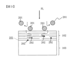
- FIG. 1 is a schematic diagram showing the state of filtration by the porous membrane of the present invention.
- FIG. 2 is a schematic diagram showing a filtration state by a conventional porous membrane.
- FIG. 3 is a schematic diagram showing a filtration state by a conventional porous membrane.
- FIG. 4 is a schematic diagram of the formation process of the porous membrane of the present invention.
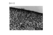
- FIG. 5 is an electron micrograph showing a cross section (part of) of a porous membrane according to one embodiment of the present invention.
- FIG. 6 is an electron micrograph showing a cross section (partial) of a conventional porous membrane.
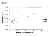
- FIG. 7 is a characteristic diagram showing the relationship between the number of surface pores and the dextran removal rate.
- FIG. 1 is a schematic diagram showing the state of filtration by the porous membrane of the present invention.
- FIG. 2 is a schematic diagram showing a filtration state by a conventional porous membrane.
- FIG. 3 is a schematic diagram showing a filtration state by a conventional
- the undiluted solution refers to the liquid to be filtered before passing through the porous membrane
- the “permeate liquid” refers to the liquid after passing through the porous membrane
- the undiluted filtration solution having a high degree of filtration difficulty refers to a liquid containing a large amount of contaminants that can clog the porous membrane in the undiluted filtration solution.
- Fouling materials are turbidity, fungi, viruses, polysaccharides, proteins, organic compounds and complexes thereof.
- Contamination substances contain coarse components (Stokes diameter: 13 nm or more) to be removed and fine components (molecular weight: 10,000 Da or less) that are preferably permeated by useful substances. many. Fine components should permeate through the porous membrane, but because they are fine, they are likely to be captured by the porous membrane and cause clogging.
- the porous membrane of the present invention exhibits high stain resistance to both coarse components and fine components in the undiluted filtrate.
- staining means that the porous membrane is clogged with coarse components (Stokes diameter: 13 nm or more) and fine components (molecular weight: 10,000 Da or less) contained in the undiluted solution in the filtration process. show. If the porous membrane is clogged with coarse components or fine components, the filtration resistance increases and the amount of liquid that can permeate the porous membrane decreases.
- a fluid such as permeate or compressed air is passed from the direction of the permeate to the direction of the filtrate, that is, in the opposite direction to the filtration.
- Back pressure washing is performed to remove coarse components captured by the porous membrane.
- Backpressure washing can easily remove coarse components that tend to accumulate outside the porous membrane, but it is difficult to remove fine components that tend to accumulate inside the porous membrane.
- the improvement in "fouling resistance" of the present invention makes it difficult for the pores of the porous membrane to become clogged regardless of whether the undiluted solution contains coarse components or fine components. .
- the porous membrane with improved stain resistance of the present invention will be described below.
- the surface portion from the surface to a thickness of 10 ⁇ m is denser than the inside, and the dextran removal rate T is 60 to 95% with a weight average molecular weight of 40,000 Da.
- the number of surface holes in the surface portion is required to be 200/ ⁇ m 2 to 2000/ ⁇ m 2 .
- a surface pore is a pore observed on the surface of the surface portion.
- the fine pores of the surface portion 102 are dense, the coarse dirt components 201 cannot penetrate into the porous membrane and do not clog the surface portion 102 of the porous membrane. It's getting harder.
- the surface portion 102 has a large number of pores, the fine contaminant components 202 enter the inside 103 from the surface portion 102 of the porous membrane in the filtration direction while being dispersed, and the porous membrane becomes difficult to stain.
- the surface portion from the surface to a thickness of 10 ⁇ m is denser than the inside, it prevents coarse contaminants and substances to be removed in the undiluted filtration solution from entering the porous membrane, and exhibits high stain resistance. .
- the fact that the surface part is more dense than the inside can be confirmed by observing the cross section of the porous membrane with a scanning electron microscope (hereinafter referred to as "SEM") at every 10 ⁇ m thick area, and the porosity of the surface part from the surface to the thickness of 10 ⁇ m is , the porosity is lower than the porosity of the inside with a thickness of 10 ⁇ m or more from the surface.
- SEM scanning electron microscope
- the image obtained by observing the cross section of the porous membrane with the SEM is binarized using the free software "ImageJ".
- Percentile in Threshold threshold for binarization
- the area of the pore portion is obtained, and the porosity is calculated by dividing it by the area of the observed porous membrane.
- the porosity of the surface portion may be smaller than that of the inside, but is preferably 55 to 90%, more preferably 63 to 80%.
- the surface is denser than the inside makes it possible to efficiently remove large dirt components and objects to be removed that are retained on the outside of the surface, especially when performing a back pressure washing process in which filtration is performed in the reverse direction during filtration. It can be discharged from the porous membrane in a short period of time, which is preferable.
- coarse contaminants and substances to be removed held on the surface can be efficiently removed from the porous membrane. It can be discharged, which is preferable.
- the inventors made it difficult for coarse components (Stokes diameter: 13 nm or more) to be removed to enter into the porous membrane, and removed coarse components that slightly entered the porous membrane by back pressure washing or the like. It was found that the removal rate of dextran having a weight-average molecular weight of 40,000 Da: T must be 60% or more in order to effectively remove the dextran from the porous membrane. By stipulating the removal rate of dextran with a specific molecular weight, it is difficult for contaminants to enter the surface, and it is possible to efficiently remove contaminants from the porous membrane by back pressure washing, etc., resulting in excellent stain resistance. A porous membrane can be obtained.
- Dextran removal rate T is preferably 68% or more, more preferably 70% or more.
- the dextran removal rate: T is 95% or less, so that fine components (molecular weight: 10,000 Da or less) that are not to be removed but are preferably permeated are not trapped in the porous membrane and are sufficiently permeated. It has been found that it exhibits high stain resistance. Further, when the dextran removal rate: T is 95% or less, the permeation resistance of the porous membrane tends to be small, and a high filtrate volume is exhibited.
- Dextran removal rate: T is more preferably 90% or less, particularly preferably 85% or less.
- Dextran removal rate with a weight average molecular weight of 40,000 Da T of 60 to 95% sufficiently prevents large fouling substances and substances to be removed in the undiluted filtration solution from entering the membrane, resulting in excellent fouling resistance. show gender.
- Dextran removal rate: T is preferably 68-90%, more preferably 70-90%, most preferably 70-85%.
- T is a cross flow linear velocity of 1.0 m/sec to the porous membrane using a dextran aqueous solution prepared so that the commercially available dextran having a weight average molecular weight of 40,000 Da is 1000 ppm and 25 ° C. It can be calculated by the following formula (3) after filtering at a transmembrane pressure difference of 10 kPa.
- T ⁇ (refractive index of undiluted solution) ⁇ (refractive index of permeated liquid) ⁇ /(refractive index of undiluted solution) ⁇ 100 Equation (3)
- the cross-flow linear velocity is a value obtained by dividing the flow rate of the undiluted solution in the direction perpendicular to the filtration direction by the cross-sectional area of the flow channel.
- the transmembrane pressure difference is the difference between the pressure on the filtrate side and the pressure on the permeated liquid side across the porous membrane.
- the fouling components in the undiluted filtration solution can be dispersed within the porous membrane. , showing excellent stain resistance. Furthermore, even if the surface pores are partially clogged by the contaminant components in the undiluted filtrate as the filtration progresses, the number of surface pores is large, so the undiluted filtration solution can pass through the porous membrane in a sufficient number of channels. , easy to show excellent stain resistance. If the number of surface pores is 200/ ⁇ m 2 or more, it is possible to sufficiently secure the flow path until washing such as back pressure washing is performed even if the undiluted filtrate is easily contaminated.
- the filtered water has a high frequency of reaching the pores on the surface of the porous membrane and tends to flow straight into the porous membrane.
- the number of surface pores of the porous membrane is more preferably 290/ ⁇ m 2 to 1500/ ⁇ m 2 , particularly preferably 350/ ⁇ m 2 to 1000/ ⁇ m 2 .
- the number of surface pores of the porous membrane is the number of pores present in the plane when the surface of the porous membrane is observed.
- an image obtained by observing the surface of the porous membrane with an SEM is binarized using free software "ImageJ".
- RenyiEntropy is selected in Threshold (threshold for binarization).
- Threshold threshold for binarization
- the number of holes in the range observed by Analyze Particles is obtained.
- the number of surface pores per unit area [number/ ⁇ m 2 ] 1,000 or more pores are observed, and the number of pores is divided by the total area of the observed region.
- FIG. 7 is a characteristic diagram showing the relationship between the number of surface pores and the dextran removal rate.
- the porous membrane of the prior art is a comparative example in FIG. It tends to be less, and there is a trade-off relationship.
- the porous membrane of the present invention is an example in FIG. 7, indicated by a circle mark, and it can be seen that the number of surface pores is 200/ ⁇ m 2 or more and the dextran removal rate is 60% or more. .
- the porous membrane of the present invention overcomes the trade-offs of the prior art, and has both a large number of surface pores and a high dextran removal rate, thereby exhibiting excellent stain resistance. be able to.
- the surface pore diameter is the diameter of the in-plane pores when observing the surface of the porous membrane.
- an image obtained by observing the surface of the porous membrane with an SEM is binarized using free software "ImageJ".
- RenyiEntropy in Threshold threshold for binarization.
- the area of each pore is obtained, and the diameter calculated assuming each pore to be a circle is taken as the surface pore diameter.
- the average surface pore diameter the pore diameters of 1,000 or more pores are averaged.
- the inventors have found that the small pores prevent coarse contaminant components and objects to be removed from entering the porous membrane, and the large number of pores It was found that a sufficient number of channels for the undiluted filtration to permeate the porous membrane can be ensured, and the fouling components can be dispersed, so that excellent fouling resistance is likely to be exhibited.
- stain resistance it is preferable from the viewpoint of stain resistance to achieve both a good (small) surface pore size and a good (large) number of surface pores.
- Both the number of surface pores and the surface pore diameter satisfy a positive correlation, and both contribute to stain resistance.
- the number of surface pores has a negative correlation with the diameter of the surface pores, it is preferable to use the X value divided by the diameter of the surface pores as an index rather than using only the number of surface pores as an index.
- the porous membrane of the present invention is formed by making the self-diffusion coefficient of the polymer relatively small, that is, making it difficult to move, in the process of forming the porous membrane, thereby preventing excessive phase separation and coarsening. It is easy to overcome the trade-off between the pore size and the number of pores by suppressing the pore size and solidifying in a state where fine pores exist in large numbers.
- X is 30 to 100/ ⁇ m 2 /nm, which is higher than the normal trade-off relationship, it is preferable for exhibiting excellent stain resistance, and 32 to 80/ ⁇ m 2 /nm is more preferable. , 50 to 70/ ⁇ m 2 /nm.
- R is 1.0 to 8.0
- fine dirt components in the undiluted filtrate can permeate the porous membrane without clogging, and the porous membrane has excellent stain resistance. It is easy to show the nature and is preferable.
- the tortuosity is also called tortuosity, and means the degree to which the channel through which the undiluted filtrate passes is tortuous. In other words, the lower the tortuous path ratio, the closer the flow path is to a straight line, and the dirt component passes through the short flow path, so clogging in the porous membrane is less likely to occur.
- FIG. 3 is a schematic diagram showing a filtration state by a conventional porous membrane.
- the tortuous road ratio: R is obtained using the following formula (1).
- R ( ⁇ /2k) 1/2 V/S Expression (1)
- ⁇ porosity
- k permeability coefficient [m 2 ]
- V pore specific volume [m 3 /g]
- S specific surface area [m 2 /g]
- k Permeability coefficient is a coefficient calculated by Equation (2) from Q [cm 3 /sec] of pure water permeation rate: Q [cm 3 /sec] of membrane area: A [m 2 ] at 25 ° C. and pressure: P [Pa] and
- the porosity: ⁇ can be determined by observing the surface region from the surface to a thickness of 10 ⁇ m with an SEM and analyzing the binarized image of the cross section of the porous membrane, as described above.
- the specific surface area: S and the pore specific volume: V can be measured by the BET method using a generally commercially available nitrogen adsorption measuring device.
- the permeability coefficient: k [m 2 ] in the formula (1) of the tortuous path ratio R is 0.5 ⁇ 10 ⁇ 17 m 2 to 5.0 ⁇ 10 ⁇ 17 m 2 . It is preferable from the viewpoint that good characteristics of are obtained stably.
- the surface of the porous membrane is collected with a commercially available freezing microtome and used as the porous membrane sample for nitrogen adsorption measurement.
- the blade can be brought into contact with the porous membrane to cut it.
- the blade is oriented parallel to the surface of the porous membrane.
- the porous membrane is cut once by moving closer to the blade at intervals of 0.5 ⁇ m. Thereafter, by setting the moving distance to 10 ⁇ m and cutting once more, a surface portion having a thickness of 10 to 10.5 ⁇ m can be obtained from the surface.
- the average value of the cross-sectional pore diameter [nm] in the cross section of the outermost surface portion is 1 nm to 99 nm, and the number of cross-sectional pores is 100/
- a cross-sectional hole means a hole observed in the cross section of the outermost surface portion.
- the average value of cross-sectional pore diameters [nm] in the cross section of the outermost surface is as fine as 1 nm to 99 nm, coarse dirt components and substances to be removed in the undiluted filtration solution are captured on the outermost surface of the porous membrane. Easy to prevent intrusion. Furthermore, since the number of cross-sectional holes is as large as 100/ ⁇ m 2 to 1000/ ⁇ m 2 , the holes are formed vertically, horizontally, and in all directions, and the flow paths are easily connected in a straight line. Clogging is less likely to occur when dirt components permeate the porous membrane. In addition, even when some of the pores are clogged, the flow paths for the undiluted filtration solution to permeate the porous membrane can be ensured.
- the surface portion 102 of the porous membrane has a dense structure, has many pores, and the pores extending three-dimensionally are connected vertically and horizontally.
- the pore size is smaller than 0.1 ⁇ m, and the number of pores forms an ultra-dense nano-network structure.
- Fine contaminant components 202 pass through any one of the plurality of connected holes without being captured by the resin portion of the network structure.
- the size of the pores of the porous membrane is adjusted according to the size of the fine components. Since 202 is less likely to be trapped in the mesh, the larger the number of pores, the better, which is preferable from the viewpoint of improving stain resistance and good permeability.
- porous membranes have a large number of pores, that is, they exist densely, the lower the tortuosity, the shorter the shortest distance formed by a number of pores. Since a channel can be secured by another fine pore, the change in the tortuosity ratio corresponding to the shortest distance is small, and the permeability can be easily maintained, which is preferable.
- the nano-network structure of the present invention is characterized in that the pore size is fine and the number of pores is large as compared with general network structures.
- a typical network structure has a large pore size and a small number of pores.
- the network structure shown in the drawings of Patent Document 1 has a pore size of 1 to 2 ⁇ m and the number of pores is 0.1/ ⁇ m 2 or less, and the pore size of the network structure of the example of Patent Document 2 is small. is 300 nm, and the number of pores is about 10/ ⁇ m 2 .
- the polymer resin part forms a network, and each pore in the network is very small as described above, and the pores are numerous and dense.
- FIG. 2 shows a schematic diagram of filtration of a stock solution, which is highly difficult to filter, with such a porous membrane.
- coarse contaminant components 201 are difficult to be blocked by the surface layer 102, enter the porous membrane and stay there, and easily cause clogging. Further, the fine dirt component 202 has a large pore size and is likely to be caught in a network structure with a high tortuosity. Compare with Figure 1. Coarse contaminant components 201 and fine contaminant components 202 contaminate the porous membrane, making it difficult to maintain filtration performance over a long period of time.
- the average cross-sectional pore size is more preferably 1.0 nm to 38 nm, particularly preferably 1.0 to 36 nm.
- the number of cross-sectional pores is more preferably 120 to 800/ ⁇ m 2 , particularly preferably 140 to 600/ ⁇ m 2 .
- the area of each hole is obtained, and the diameter calculated assuming each hole as a circle is taken as the cross-sectional hole diameter.
- the average value of cross-sectional pore diameters the pore diameters of 1,000 or more pores are averaged.
- the number of cross-sectional holes is divided by the total area of the analyzed image to obtain the number of holes per unit area. Similar to the pore diameter, it is calculated by analyzing an image containing 1,000 or more pores.
- the inventors found that even in the cross section of the outermost surface, the cross-sectional pores are small, so that coarse dirt components and substances to be removed in the undiluted filtration solution are prevented from entering the porous membrane.
- the large number of cross-sectional pores ensures a sufficient number of flow paths for the undiluted filtration solution to permeate the porous membrane, and the fouling components can be dispersed, thereby easily exhibiting excellent fouling resistance. Since the cross-sectional pore number and the cross-sectional pore size are correlated and both contribute to the stain resistance, it is preferable to use the Y value, which takes into consideration both, as an index of the stain resistance.
- the porous membrane of the present invention exhibits excellent stain resistance when Y is 3 to 10/ ⁇ m 2 /nm, which is higher than the usual trade-off relationship . /nm, and particularly preferably 5 to 10/ ⁇ m 2 /nm.
- the standard deviation of the cross-sectional pore diameter [nm] is 1.0 nm to 50 nm, so that the load of fouling substances on the porous membrane can be made uniform, and excellent fouling resistance is achieved. is easy to show, which is preferable. More preferably, the standard deviation of the cross-sectional pore size is 1.0 nm to 35 nm.
- the standard deviation of the cross-sectional pore size can be calculated by obtaining the data of each cross-sectional pore size by binarizing and analyzing the TEM image obtained by observing the cross section of the porous membrane as described above.
- the standard deviation of the surface pore diameter [nm] of the surface portion of the porous membrane is 0.5 to 5.0 nm, the load of fouling substances on the porous membrane can be made uniform, resulting in excellent fouling resistance. is easy to show, which is preferable.
- the smaller the standard deviation of the surface pore diameter the smaller the variation in pore diameter.
- the standard deviation of the surface pore diameter can be calculated by obtaining data on each surface pore diameter by binarizing and analyzing the SEM image obtained by observing the surface of the porous membrane as described above.
- the porous membrane of the present invention comprises step (A): dissolving a polymer in a solvent to obtain a polymer solution, and then step (B): solidifying the polymer solution in a non-solvent to form a porous membrane.
- a self-diffusion coefficient [m 2 /sec ] is 0.8 ⁇ 10 ⁇ 11 m 2 /sec to 1.6 ⁇ 10 ⁇ 11 m 2 /sec
- the non-solvent used in step (B) contains 90 to 100% by weight of water
- the non-solvent can be obtained by a production method in which the temperature of is 6°C to 45°C.
- the type of polymer used in step (A) is not particularly limited, but specific examples include polysulfone-based resins, polyethersulfone-based resins, polyvinylidene fluoride-based resins, nylon, cellulose acetate, cellulose acetate propionate, and the like.
- the membrane contains polyvinylidene fluoride resin, which has excellent chemical resistance.
- a polyvinylidene fluoride resin refers to a vinylidene fluoride homopolymer or a vinylidene fluoride copolymer.
- the vinylidene fluoride copolymer refers to a polymer having a vinylidene fluoride residue structure.
- a polymer having a vinylidene fluoride residue structure is typically a copolymer of a vinylidene fluoride monomer and other fluorine-based monomers.
- fluoromonomers examples include vinyl fluoride, ethylene tetrafluoride, propylene hexafluoride, and ethylene trifluoride chloride.
- ethylene or the like other than the fluorine-based monomer may be copolymerized to the extent that the effects of the present invention are not impaired.
- the polyvinylidene fluoride-based resin is more preferably contained in an amount of 50% by weight or more, particularly preferably 60% by weight or more. It is preferable that the weight average molecular weight of the polymer is 5 to 1,000,000 Da because the self-diffusion coefficient described later can be easily controlled within a relatively slow and suitable range. Moreover, you may use polymer
- the solvent preferably contains a good solvent.
- the term "good solvent” refers to a solvent capable of dissolving 5% by weight or more of a polymer even in a low temperature range of 60°C or less.
- Good solvents include, for example, N-methyl-2-pyrrolidone (hereinafter “NMP”), 2-pyrrolidone (hereinafter “2P”), ⁇ -caprolactam (hereinafter “ ⁇ -CL”), dimethylacetamide, dimethyl formamide, methyl ethyl ketone, acetone, tetrahydrofuran, tetramethyl urea, trimethyl phosphate, or a mixed solvent thereof. It is more preferable that the good solvent is contained in the solvent in an amount of 40% by weight or more, particularly preferably 60% by weight or more.
- non-solvents include water, hexane, pentane, benzene, toluene, methanol, ethanol, carbon tetrachloride, o-dichlorobenzene, trichloroethylene, ethylene glycol, diethylene glycol, triethylene glycol, propylene glycol, butylene glycol, pentane.
- the concentration (% by weight) of the polymer in the polymer solution is preferably equal to or higher than the entanglement concentration in order to control the self-diffusion coefficient within a suitable range, more specifically, preferably 10 to 40% by weight. 12 to 30% by weight is more preferred, and 15 to 25% by weight is particularly preferred. It was found that a polymer concentration of 10% by weight or more can make the self-diffusion coefficient relatively slow, and that the porous membrane can be coagulated with a large number of fine pores.
- the polymer concentration is more preferably 12% by weight or more, particularly preferably 15% by weight or more. Further, by setting the concentration of the polymer to 40% by weight or less, the proportion of the polymer in the porous membrane can be reduced, and a sufficient number of pores can be secured.
- the polymer concentration is more preferably 30% by weight or less, particularly preferably 25% by weight or less.
- FIG. 4 is a schematic diagram showing the process of forming a porous membrane in step (B).
- Phase separation progresses in the polymer solution in order from (a) to (f) in FIG. 4, and the portion with a high polymer concentration (the phase 301 containing a large amount of polymer) coarsens.
- the phase 301 containing a large amount of polymer coarsens.
- exchange between the solvent and the non-solvent progresses, and when the concentration of the non-solvent rises above a certain level, the polymer solidifies and the structure of the porous membrane is fixed.
- the phase 302 containing a large amount of solvent becomes the pores of the porous membrane.
- the self-diffusion coefficient of the polymer is set to a relatively low range of 0.8 ⁇ 10 ⁇ 11 m 2 /sec to 1.6.
- the self-diffusion coefficient is 0.8 ⁇ 10 ⁇ 11 m 2 /sec or more, the diffusion coefficient is sufficient for phase separation between the polymer and the solvent, and pores are easily formed.
- Pores are less likely to form when diffusion of the polymer is slow enough to cause phase separation.
- the self-diffusion coefficient is 1.6 ⁇ 10 ⁇ 11 m 2 /sec or less, excessive phase separation and coarsening are suppressed, coalescence of pores is suppressed, and many fine pores are easily formed. . That is, by appropriately controlling the self-diffusion coefficient of the polymer within a relatively low range, a porous membrane having many fine pores can be formed.
- the self-diffusion coefficient is more preferably 0.8 ⁇ 10 ⁇ 11 m 2 /sec to 1.4 ⁇ 10 ⁇ 11 m 2 /sec, more preferably 0.8 ⁇ 10 ⁇ 11 m 2 / sec to 1.1 ⁇ More preferably, it is 10 ⁇ 11 m 2 /sec.
- the non-solvent used for solidification contains 90 to 100% by weight of water, so that solidification is rapid, and the self-diffusion coefficient in the polymer solution affects the speed of phase separation and coarsening. Easy to give. That is, it is easy to obtain the effect of controlling the self-diffusion coefficient in the polymer solution to a relatively low range.
- the temperature of the non-solvent is 6° C. to 45° C., solidification is rapid, and the self-diffusion coefficient in the polymer solution tends to affect the speed of phase separation and coarsening.
- the temperature of the non-solvent is more preferably 10°C to 35°C, more preferably 15°C to 30°C.
- Hydrogen bond donor and hydrogen bond acceptor solvents are not particularly limited, but specific examples include 2P, ⁇ -CL, 1,3-dimethylurea, N-methylacetamide, hydantoin, 2-imidazolidinone, DL - includes pyroglutamic acid and the like.
- the polymer to be dissolved contains a polymer having hydrogen bond donor and/or hydrogen bond acceptor properties, so that the self-diffusion coefficient of the polymer can be easily controlled within an appropriate range, which is preferable.
- the polymer has hydrogen bond donor and/or hydrogen bond acceptor properties, so that it interacts with a solvent having hydrogen bond donor and hydrogen bond acceptor properties through hydrogen bonding, and the self-diffusion coefficient of the polymer is relatively slow. This is because it is easy to control within a suitable range.
- the polymer having hydrogen bond donor and/or hydrogen bond acceptor properties should be contained in the porous membrane in an amount of 10% to 50% by weight. more preferred.
- the number of moles of the hydrogen-bond-donating functional groups contained in the solvent in step (A) above is the number of moles of the hydrogen-bond-donating functional groups contained in the polymer having hydrogen-bond-donating and/or hydrogen-bond-accepting properties.
- the divided value is 1.0 to 12
- the hydrogen bond between the polymer and the solvent is in an appropriate range, and the self-diffusion coefficient of the polymer is relatively slow and easy to control within an appropriate range.
- the numerical value is more preferably 2.0 to 9.0, particularly preferably 5.4 to 8.0.
- the porous membrane of the present invention may further comprise other layers.
- the porous membrane of the present invention is preferably arranged on the surface.
- the above-mentioned other layer is not particularly limited as long as it is a constituent element capable of overlapping with the porous membrane to form a layered structure, but the above-mentioned other layer is preferably a support.
- the term "support” refers to a structure that physically reinforces the porous membrane and has higher breaking strength than the porous membrane.
- a section of the obtained surface portion was measured by the BET method using a commercially available nitrogen adsorption measurement device (manufactured by Microtrack Bell; BELSORP-miniII) to determine the pore specific volume: V [m 3 /g] and the specific surface area S [m 2 /g] was measured.
- the area of each surface pore was obtained, and the diameter calculated on the assumption that each surface pore was a circle was taken as the surface pore diameter.
- the surface pore diameters of 1000 or more pores were averaged.
- the standard deviation was obtained from the data of each surface pore size. The number of surface pores was divided by the total area of the observed region to obtain the number of surface pores per unit area.
- a cross section of the outermost surface of the porous membrane was observed with a TEM (manufactured by JEOL Ltd.; JEM-1400Plus), an image was obtained, and binarized using free software "ImageJ".
- Minimum was selected for Threshold (threshold for binarization).
- Area in Analyze Particles the area of each cross-sectional pore was obtained, and the diameter calculated assuming each cross-sectional pore to be a circle was taken as the cross-sectional pore diameter.
- the cross-sectional pore diameters of 1,000 or more cross-sectional pores are averaged.
- the number of cross-sectional holes per unit area was obtained by dividing the number of cross-sectional holes by the total area of the analyzed region.
- the surface pore diameter is calculated by analyzing an image containing 1,000 or more pores.
- the standard deviation was obtained from the data of each cross-sectional pore size.
- the average value of the cross-sectional pore diameter [nm] in the cross section of the outermost surface portion is 1 nm to 99 nm, and the number of cross-sectional pores is 100/
- a network structure of ⁇ m 2 to 1000/ ⁇ m 2 was determined to have a nano-network structure.
- Self-diffusion coefficients of polymers were determined by all-atom molecular dynamics calculations.
- a polymer solution system was prepared so as to have the polymer concentration (% by weight) actually used.
- one model polymer chain was modeled to have a molecular weight of 800 to 6000 and 1/200 to 1/5 of the weight average molecular weight of the polymer actually used.
- GAFF2 was used as the potential parameter used in the molecular dynamics calculation.
- a constant pressure-temperature ensemble was constructed by controlling the temperature at 25° C. and the pressure at 1 bar.
- the short-range Lennard-Johns interaction was handled by applying a switch function from 1.0 nm and cutting off at 1.2 nm, and the long-range electrostatic interaction was calculated by the Particle Mesh Ewald method.
- the unit cell length was adjusted so as to obtain an average density, and an additional calculation of 11 ns was performed with a constant temperature ensemble.
- the mean square displacement (MSD) of each atom of the polymer was obtained, and the self-diffusion coefficient was calculated from the following formula (4).
- the value obtained by dividing log(MSD) by log(t) was in the range of 0.9 to 1.1 for the range of MSD and t used to calculate D.
- the weighted average value of the self-diffusion coefficient of each polymer based on the weight percentage of the polymer is taken as the self-diffusion coefficient of the polymer in the polymer solution. bottom.
- Example 1 A hollow fiber porous membrane containing a support obtained by the following method was used as the porous membrane. 38% by mass of PVDF (Kureha; KF1300, weight average molecular weight: 350,000 Da) and 62% by mass of ⁇ -butyrolactone were mixed and dissolved at 160° C. to prepare a stock solution of the support membrane.
- This support membrane undiluted solution was discharged from a double-tube nozzle while being accompanied by an aqueous 85 mass % ⁇ -butyrolactone solution as a cavity-forming liquid.
- the discharged support membrane undiluted solution was solidified in a cooling bath containing an 85% by mass ⁇ -butyrolactone aqueous solution at a temperature of 20° C. placed 30 mm below the spinneret to prepare a hollow fiber support having a spherical structure.
- PVDF1 manufactured by Arkema; “Kynar” (registered trademark) 710, weight average molecular weight of 180,000 Da
- cellulose diacetate manufactured by Eastman; CA-398-3
- cellulose triacetate manufactured by Eastman; CA-436-80S
- NMP 68.8% by mass of NMP
- 2P 12% by mass of 2P
- the polymer solution was uniformly applied to the outer surface of the hollow fiber support at 10 m/min (thickness: 50 ⁇ m).
- the support coated with the polymer solution is taken up at 10 m/min, and after 1 second from the coating, it is passed through a coagulation bath of distilled water at 25° C. for 10 seconds so as to be immersed and solidified, resulting in a porous membrane having a three-dimensional network structure. formed.
- Table 1 shows the evaluation results of the obtained porous membrane.
- the surface portion of the porous membrane from the surface to a thickness of 10 ⁇ m was denser than the inside.
- FIG. 5 shows a TEM image of the cross section of the outermost surface of the porous membrane.
- Example 2 A porous membrane was obtained in the same manner as in Example 1, except that 2P in the polymer solution was changed to ⁇ -CL.
- Table 1 shows the evaluation results of the porous membrane.
- the surface portion of the porous membrane from the surface to a thickness of 10 ⁇ m was denser than the inside.
- the resulting porous membrane had a tortuosity R of 4.1, a dextran removal rate of T of 65%, and the number of surface pores: 291/ ⁇ m 2 .
- the number of surface pores was divided by the average surface pore diameter. Value: X was good at 33/ ⁇ m 2 /nm.
- the filtration flux ratio (F2/F1) was 0.58, and the filtration flux could be maintained even after long-term use.
- Example 3 A porous membrane was obtained in the same manner as in Example 1 except that the composition ratio of the polymer solution was changed as shown in Table 1.
- Table 1 shows the evaluation results of the porous membrane.
- the surface portion of the porous membrane from the surface to a thickness of 10 ⁇ m was denser than the inside.
- the tortuosity of the obtained porous membrane R: 5.9, Dextran removal rate: T: 72%, Number of surface pores: 329/ ⁇ m 2 , The number of surface pores was divided by the average surface pore diameter. Value: X was good at 46/ ⁇ m 2 /nm.
- the filtration flux ratio (F2/F1) was 0.55, and the filtration flux could be maintained even after long-term use.
- Example 4 A porous membrane was obtained in the same manner as in Example 1 except that the composition ratio of the polymer solution was changed as shown in Table 1.
- the porous membrane had a nano-network structure.
- Table 1 shows the evaluation results of the porous membrane.
- the surface portion of the porous membrane from the surface to a thickness of 10 ⁇ m was denser than the inside.
- the tortuous path ratio of the obtained porous membrane R: 4.9, dextran removal rate: T: 69%, number of surface pores: 420/ ⁇ m 2 , the number of surface pores was divided by the average surface pore diameter.
- Value: X was good at 58/ ⁇ m 2 /nm.
- the filtration flux ratio (F2/F1) was 0.62, and the filtration flux could be maintained even after long-term use.
- Example 5 (Example 5) (ix) Filterability of the porous membrane was evaluated using the filtration evaluation method for aqueous gelatin solution.
- the porous membrane was used to represent Example 1. When the aqueous gelatin solution was filtered, the removal rate of gelatin was 65% for T gelatin , and the filtration flux was good at 70 L/m 2 /h.
- Table 3 shows the filtration evaluation results of the gelatin solution.
- the tortuous path ratio of the porous membrane used for evaluation: R is 4.9, the dextran removal rate is 72%, the number of surface pores is 444/ ⁇ m 2 , and the number of surface pores is the average value of the surface pore diameter. Value divided by: X was 62/ ⁇ m 2 /nm.
- Example 6 Filterability of the porous membrane was evaluated using the apple juice filtration evaluation method.
- the porous membrane was used to represent Example 1.
- the removal rate of apple juice was 99.9% for T apple
- the filtration flux was 37 L/m 2 /h, which was good.
- Table 4 shows the filtration evaluation results of the apple juice.
- the tortuous path ratio of the porous membrane used for evaluation: R is 4.9
- the dextran removal rate is 72%
- the number of surface pores is 444/ ⁇ m 2
- the number of surface pores is the average value of the surface pore diameter. Value divided by: X was 62/ ⁇ m 2 /nm.
- Comparative example 2 In the film formation of Comparative Example 1, PVDF1 in the polymer solution was changed to PVDF2 (manufactured by Arkema: HSV900, melt viscosity 4700 Pa s), and a porous film was formed in the same manner as in Comparative Example 1 except that the composition ratio was changed. A membrane was obtained. Table 2 shows the evaluation results of the porous membrane. The surface portion of the porous membrane from the surface to a thickness of 10 ⁇ m was denser than the inside, but the number of surface pores and the dextran removal rate: T did not satisfy the conditions. (xi) In the factory wastewater filtration evaluation method, the initial ratio (F2/F1) of the filtration flux was 0.40, and the filtration flux greatly decreased after long-term use.
- FIG. 6 shows a TEM image of the cross section of the outermost surface of the porous membrane.
- Table 2 shows the evaluation results.
- the porous membrane did not have a nano-network structure.
- the surface portion of the porous membrane from the surface to a thickness of 10 ⁇ m was denser than the inside, but the number of surface pores, tortuosity: R, and dextran removal rate: T did not satisfy the conditions.
- xi In the method for evaluating the filtration of industrial wastewater, the amount of permeated liquid was remarkably small, and it was difficult to measure the filtration flux, which was below the lower limit of measurement. It is considered that the filtration flux was extremely low because the number of surface pores was small and the dextran removal rate: T was excessive.
- Comparative Example 5 A porous membrane was obtained in the same manner as in the membrane formation of Comparative Example 3, except that the composition ratio of the polymer solution was changed.
- the composition ratio of 2P was set to 30% by mass.
- Table 2 shows the evaluation results of the porous membrane.
- the surface portion of the porous membrane from the surface to a thickness of 10 ⁇ m was denser than the inside, but the number of surface pores, tortuosity: R, and dextran removal rate: T did not satisfy the conditions.
- the initial ratio (F2/F1) of the filtration flux was 0.45, and the filtration flux greatly decreased after long-term use.
- Example 6 A porous membrane was obtained in the same manner as in Example 1, except that 2P in the polymer solution was changed to ⁇ -butyrolactone. Table 2 shows the evaluation results of the porous membrane. The surface portion of the porous membrane from the surface to a thickness of 10 ⁇ m was denser than the inside, but the average surface pore size, tortuosity: R, and dextran removal rate: T did not satisfy the conditions. (xi) In the factory wastewater filtration evaluation method, the initial ratio (F2/F1) of the filtration flux was 0.40, and the filtration flux greatly decreased after long-term use.
- the polymer solution was uniformly applied to the outer surface of the hollow fiber support at 10 m/min (thickness: 50 ⁇ m).
- the support coated with the polymer solution is taken up at 10 m/min, and after 1 second from the coating, it is passed through a coagulation bath of distilled water at 15° C. for 10 seconds so as to be immersed and solidified, resulting in a porous membrane having a three-dimensional network structure. formed.
- Table 5 shows the evaluation results of the obtained porous membrane.
- the surface portion of the porous membrane from the surface to a thickness of 10 ⁇ m was denser than the inside.
- the polymer solution was uniformly applied to the outer surface of the hollow fiber support at 10 m/min (thickness: 50 ⁇ m).
- the support coated with the polymer solution is taken up at 10 m/min, and after 1 second from coating, it is passed through a coagulation bath of distilled water at 25° C. for 30 seconds to be coagulated, resulting in a porous membrane having a three-dimensional network structure. formed.
- Table 5 shows the evaluation results of the obtained porous membrane.
- the surface portion of the porous membrane from the surface to a thickness of 10 ⁇ m was denser than the inside.
- T Dextran removal rate of the resulting porous membrane: T is 24%, number of surface pores: 2/ ⁇ m 2 , value obtained by dividing the number of surface pores by the average surface pore diameter: X is 0.01/ ⁇ m 2 /nm, and (xi) in the evaluation method for filtration of factory wastewater, the amount of permeated liquid was remarkably small, and it was difficult to measure the filtration flux, which was below the lower limit of measurement. It is considered that the filtration flux was extremely low due to the small number of surface pores and the low dextran removal rate: T.
- the polymer solution was uniformly applied to the outer surface of the hollow fiber support at 10 m/min (thickness: 50 ⁇ m).
- the support coated with the polymer solution is taken up at 10 m/min, and after 1 second from coating, it is passed through a coagulation bath of distilled water at 25° C. for 30 seconds to be coagulated, resulting in a porous membrane having a three-dimensional network structure. formed.
- Table 5 shows the evaluation results of the obtained porous membrane.
- the surface portion of the porous membrane from the surface to a thickness of 10 ⁇ m was denser than the inside.
- FIG. 10 shows the relationship between the self-diffusion coefficient and the initial filtration flux ratio (F2/F1) for the example and the comparative example. From the examples and comparative examples, the initial ratio of the filtration flux was 0.50 or more when the self-diffusion coefficient ranged from 0.8 ⁇ 10 ⁇ 11 m 2 /sec to 1.6 ⁇ 10 ⁇ 11 m 2 /sec. Good filtration performance was maintained even after long-term operation.
Abstract
従来の多孔質膜は、ウイルス等の比較的大きな成分の除去性を向上させるために、比較的大きな孔径の網目構造であった。汚れやすいろ過原液をろ過すると、多孔質膜内に汚れ物質が蓄積しやすく、多孔質膜に目詰まり等が発生し、多孔質膜の汚れが発生しやすかった。そこで、高い耐汚れ性と高精度の除去性を有する多孔質膜を提供することを目的とする。かかる目的を達成するため、少なくとも一方の表面において、表面から厚み10μmまでの表面部が、内部より緻密で、重量平均分子量4万Daのデキストラン除去率:Tが60~95%で、前記表面部の表面において観察される表面孔の単位面積あたりの数が200個/μm2~2000個/μm2である多孔質膜を提供する。
Description
本発明は、多孔質膜及び多孔質膜の製造方法に関する。
近年、精密ろ過膜や限外ろ過膜等の多孔質膜は、浄水又は排水処理等の水処理分野、血液浄化等の医療分野、食品工業分野等、様々な分野で利用されている。最近では、ろ過が難しいとされてきた「汚れやすいろ過原液」に対して、効率よくろ過できる汚れ耐性が高い多孔質膜が求められている。多孔質膜が汚れやすいろ過原液とは、ろ過原液中に含まれる汚れ物質が、従来よりも多いことが特徴である。汚れ物質の中には、除去対象となる粗大な成分(ストークス径:13nm以上)と、除去対象ではなく有用物等で透過することが好ましい微細な成分(分子量:1万Da以下)が含まれていることが多い。
多孔質膜の汚れ耐性とは、高精度な除去を行う場合に、汚れ物質または除去対象物である粗大な成分および微細な成分のいずれに対しても、多孔質膜の空孔に詰まる等の問題を軽減し、除去対象物の除去効率および透水性が長時間安定に維持できることである。
耐汚れ性を示す多孔質膜としては、特許文献1には、巨大孔を有する三次元網目構造とすることで、対象物の高い除去率と、水の高い透過係数を合わせ有する多孔質膜が開示されている。
また特許文献2には、三次元網目構造の孔径を微細化することで、ウイルス等の対象物の除去率を向上させる技術が開示されている。特許文献2に開示の三次元網目構造は、平均直径が0.01μm以上1μm以下で、実質的に5μm以上のマクロボイドを有しない。
しかしながら、特許文献1に記載のような巨大孔を有する三次元網目構造では、平均孔径は大きく、クモの巣状の三次元構造を有するため、粗大な成分は多孔質膜に侵入し多孔質膜を汚す。また、絡み合った微細な糸状体構造の隙間に、微粒子が補足されるので、多孔質膜が目詰まりしやすく、耐汚れ性が十分でなかった。特許文献2に記載の多孔質膜は、ウイルス等の比較的大きな成分を除去対象物とし、除去性を向上させるに留まっており、網目構造は比較的大きな孔径で孔数が少ない。よって、多孔質膜内に汚れ物質が蓄積しやすく、汚れやすいろ過原液に対しては耐汚れ性が犠牲となっていた。
一方で、上述のような汚れやすいろ過原液に対しては、多孔質膜の汚れが著しく起こるため、ろ過が難しい。このような汚れやすいろ過原液に対しても、ろ過を可能とする高い耐汚れ性を有する多孔質膜が求められている。
そこで、本発明は、粗大な成分は多孔質膜の外表面で除去し、微細な成分は効率的に多孔質膜を透過させることで、優れた耐汚れ性を有する多孔質膜を提供することを目的とする。外表面とは、多孔質膜の表面部、言い換えると表面層において、内部と反対側にあたる外側の表面である。
上記課題を解決するため、本発明は、以下の構成からなる多孔質膜を提供する。
1.少なくとも一方の表面において、表面から厚み10μmまでの表面部が、内部より緻密で、重量平均分子量4万Daのデキストラン除去率:Tが60%~95%であり、前記表面部の表面において観察される孔(以下、表面孔とする)の単位面積あたりの数が200個/μm2~2000個/μm2である多孔質膜である。
2.前記表面部の表面孔径[nm]の平均値が5.0nm~12nmである1に記載の多孔質膜である。
3.前記表面孔の単位面積あたりの数[個/μm2]を前記表面孔径[nm]の平均値で除した値:Xが30~100個/μm2/nmである1または2に記載の多孔質膜である。
4.前記表面部の式(1)で示す曲路率:Rが1.0~8.0である1~3のいずれかに記載の多孔質膜である。
R=(ε/2k)1/2・V/S ・・・・・式(1)
ε:空隙率 k:透過係数[m2]
V:細孔比容積[m3/g] S:比表面積[m2/g]
ここで、k:透過係数は、25℃で、圧力:P[Pa]における膜面積:A[m2]の純水透水量:Q[cm3/sec]から式(2)で算出する係数
k=8.76×Q/A/P×10-15 ・・・・・式(2)
5.前記表面部の表面から厚み2μmまでの最表面部に、前記最表面部の断面において観察される孔(以下、断面孔とする)の単位面積あたりの数が100個/μm2~1000個/μm2であり、かつ、断面孔径[nm]の平均値が1nm~99nmであるナノ網目構造を有する1~4のいずれかに記載の多孔質膜である。
6.前記断面孔の単位面積あたりの数[個/μm2]を前記断面孔径[nm]の平均値で除した値:Yが3~10個/μm2/nmである5に記載の多孔質膜である。
7.前記最表面部の前記断面孔径[nm]の標準偏差が1.0nm~50nmである5または6に記載の多孔質膜である。
8.前記表面部の前記表面孔径[nm]の標準偏差が0.5nm~5.0nmである2~7のいずれかに記載の多孔質膜である。
9.前記曲路率:Rにおける前記式(2)で示す透過係数:k[m2]が、0.5×10⁻¹⁷m2~5.0×10⁻¹⁷m2である4~8のいずれかに記載の多孔質膜である。
10.工程(A):高分子を溶媒に溶解して高分子溶液を得る工程と、その後に、工程(B):高分子溶液を非溶媒中で凝固させて多孔質膜を形成する多孔質膜形成工程とを含む多孔質膜の製造方法であって、工程(A)は、高分子溶液中において前記溶解される高分子の全原子分子動力学計算で算出される自己拡散係数[m2/sec]が0.8×10-11m2/sec~1.6×10-11m2/secであり、工程(B)は、前記非溶媒が90~100重量%の水を含み、かつ、前記非溶媒の温度が6℃~45℃である、多孔質膜の製造方法を提供する。
11.前記工程(A)において、前記溶媒は水素結合ドナー性および水素結合アクセプター性を有する分子量500Da以下の水素結合性溶媒を含み、前記溶解される高分子は水素結合ドナー性および/または水素結合アクセプター性を有する高分子を含む、10に記載の多孔質膜の製造方法である。
12.前記工程(A)の前記水素結合性溶媒が含む水素結合アクセプター性官能基のmol数を、水素結合ドナー性および/または水素結合アクセプター性を有する高分子が含む前記水素結合ドナー性官能基のmol数で除した値が、1.0~12である11に記載の多孔質膜の製造方法である。
13.前記工程(A)の前記水素結合性溶媒が含む水素結合ドナー性官能基のmol数を、水素結合ドナー性および/または水素結合アクセプター性を有する高分子が含む前記水素結合アクセプター性官能基のmol数で除した値が、0.5~5.0である11または12に記載の多孔質膜の製造方法である。
14.1~9のいずれかに記載の多孔質膜を用いた液体のろ過方法である。
本発明によれば、粗大な成分は多孔質膜の外表面で除去し、微細な成分は効率的に多孔質膜を透過させることで、優れた耐汚れ性を有する多孔質膜を提供することができる。これにより、汚れやすいろ過原液を高精度にろ過できるとともに、汚れによる詰まりを抑制し長時間の使用においてもろ過流束を維持できる。
以下に、本発明の実施形態について図面を参照しながら詳細に説明するが、本発明はこれらによって何ら限定されるものではない。なお、本明細書において、「質量」と「重量」は同義である。また、「ろ過原液」とは多孔質膜を透過する前のろ過対象液のことであり、「透過液」は多孔質膜を透過した後の液体を指す。また、ろ過難度が高いろ過原液とは、ろ過原液中に多孔質膜に目詰まりし得る汚れ物質が多い液を指す。汚れ物質は、濁質、菌類、ウイルス、多糖類、タンパク質、有機化合物およびそれらの複合体である。汚れ物質の中には、除去対象となる粗大な成分(ストークス径:13nm以上)と、有用物等で透過させることが好ましい微細な成分(分子量:1万Da以下)が含まれていることが多い。微細な成分は多孔質膜を透過すべきものであるが、微細なゆえに、多孔質膜に補足されやすく目詰まりの原因となってしまう。本発明の多孔質膜は、粗大な成分および微細な成分のいずれが多いろ過原液に対しても、高い耐汚れ性を示す。
耐汚れ性に関して、汚れるとは、ろ過工程においてろ過原液中に含まれる粗大な成分(ストークス径:13nm以上)や微細な成分(分子量:1万Da以下)等で多孔質膜が閉塞することを表す。粗大な成分や微細な成分で多孔質膜の閉塞が進むと、ろ過抵抗が上昇し、多孔質膜を透過できる液量が低下する。
一般には、多孔質膜に蓄積した濁質の粗大成分などを細孔から除去するために、透過液方向からろ過原液方向に向けて透過液や圧縮空気などの流体を流し、つまりろ過と逆方向から逆圧洗浄を行って、多孔質膜に補足された粗大成分などを取り除いている。逆圧洗浄では、多孔質膜外部に蓄積しやすい粗大な成分の除去は行いやすいが、多孔質膜内部に蓄積しやすい微細な成分の除去は難しい。本発明の「耐汚れ性」向上は、ろ過原液中に粗大な成分と微細な成分と含まれていても、どちらの成分であっても多孔質膜の細孔が閉塞しにくくするものである。本発明の耐汚れ性を向上した多孔質膜について、以下、説明する。
<多孔質膜について>
本発明の実施形態に係る多孔質膜は、少なくとも一方の表面において、表面から厚み10μmまでの表面部が内部より緻密で、重量平均分子量4万Daのデキストラン除去率:Tが60~95%で、前記表面部の表面孔の数が200個/μm2~2000個/μm2であることを必要とする。表面孔とは、前記表面部の表面において観察される孔である。
本発明の実施形態に係る多孔質膜は、少なくとも一方の表面において、表面から厚み10μmまでの表面部が内部より緻密で、重量平均分子量4万Daのデキストラン除去率:Tが60~95%で、前記表面部の表面孔の数が200個/μm2~2000個/μm2であることを必要とする。表面孔とは、前記表面部の表面において観察される孔である。
図1には、本発明の多孔質膜でろ過難度が高いろ過原液をろ過する際の模式図を示す。図1は多孔質膜の断面の一部を示す概念模式図である。多孔質膜101は表面部102と内部103を含む。表面部102は内部103よりも緻密な構造である。図1中、表面部102に描画した実線は網目構造を模式的に示している。ろ過方向FLは表面部102から内部103に向かう方向である。ろ過原液のろ過対象物には、粗大な汚れ成分201と微細な汚れ成分202が含まれている。粗大な汚れ成分201は表面部102の微細孔が緻密であるために、多孔質膜内に侵入することができず、多孔質膜の表面部102を閉塞することはなく、多孔質膜は汚れにくくなっている。一方、表面部102に多数の孔が開いているため、微細な汚れ成分202は、ろ過方向に多孔質膜の表面部102から内部103に分散して進入し、多孔質膜は汚れにくくなっている。
すなわち、表面から厚み10μmまでの表面部が、内部より緻密であることで、ろ過原液中の粗大な汚れ物質や除去対象物が多孔質膜内に侵入することを防ぎ、高い耐汚れ性を示す。表面部が内部より緻密であることは、多孔質膜の断面を走査型電子顕微鏡(以降、「SEM」)で厚み10μmごとの領域を観察し、表面から厚み10μmまでの表面部の空隙率が、表面から厚み10μm以上の内部の空隙率よりも低いことで確認できる。空隙率を求める場合には、多孔質膜の断面を観察したSEMで得た画像を、フリーソフト「ImageJ」を使って二値化する。二値化する際は、Subtract Backgroundにて1pixelとしてCreate Backgroundした後、Threshold(二値化の閾値)で条件:Persentileを選択する。得られた二値化画像において、Analyze ParticlesでAreaを選択することで、細孔部の面積を求め、観察した多孔質膜の面積で除して空隙率を算出する。表面部の空隙率は、内部より小さければよいが、55~90%であることが好ましく、63~80%であることがさらに好ましい。
表面部が内部より緻密であることは、特に、ろ過の途中で、逆向きにろ過する逆圧洗浄工程を行う場合に、表面部の外側で保持した粗大な汚れ成分や除去対象物を効率的に多孔質膜から排出することができ、好ましい。また、ろ過の途中にろ過方向と垂直な向きに液体を流すクロスフローろ過や、フラッシング工程を行う場合にも、表面部で保持した粗大な汚れ物質や除去対象物を効率的に多孔質膜から排出することができ、好ましい。
発明者らは、除去対象となる粗大な成分(ストークス径:13nm以上)を多孔質膜内へ侵入させにくくし、またわずかに多孔質膜に侵入した粗大な成分を、逆圧洗浄などによって効率的に多孔質膜から排出するために、重量平均分子量4万Daのデキストラン除去率:Tが60%以上を示すことが必要であることを見出した。特定の分子量のデキストランの除去率を規定することで、表面部へ汚れ物質が侵入しにくく、また逆圧洗浄などによって効率的に多孔質膜から汚れ物質を排出可能な、耐汚れ性に優れた多孔質膜を得ることができる。
デキストラン除去率:Tは68%以上であることが好ましく、70%以上であることがさらに好ましい。また、デキストラン除去率:Tは95%以下であることで、除去対象ではなく透過することが好ましい微細な成分(分子量:1万Da以下)を多孔質膜に捕捉することなく、十分に透過して高い耐汚れ性を示すことを見出した。また、デキストラン除去率:Tは95%以下であることで、多孔質膜の透過抵抗が小さくなりやすく、高いろ過液量を示す。デキストラン除去率:Tは90%以下であることがより好ましく、とりわけ85%以下が好ましい。重量平均分子量4万Daのデキストラン除去率:Tが60~95%であることで、ろ過原液中の粗大な汚れ物質や除去対象物が膜内に侵入することを十分に防ぎ、優れた耐汚れ性を示す。デキストラン除去率:Tは、68~90%であることが好ましく、70~90%であるさらに好ましく、70~85%であることが最も好ましい。
デキストラン除去率:Tは、市販の重量平均分子量4万Daのデキストランが1000ppm、25℃となるように調製したデキストラン水溶液を用いて、多孔質膜に対してクロスフロー線速度1.0m/sec、膜間差圧10kPaでろ過し、下記式(3)で算出することができる。
T={(原液の屈折率)-(透過液の屈折率)}/(原液の屈折率)×100 ・・・式(3)
ここで、クロスフロー線速度は、ろ過原液のろ過方向と垂直な方向の流量を、該流れの流路の断面積で除した値である。また、膜間差圧とは、多孔質膜を隔てたろ過原液側の圧力と、透過液側の圧力の差である。
T={(原液の屈折率)-(透過液の屈折率)}/(原液の屈折率)×100 ・・・式(3)
ここで、クロスフロー線速度は、ろ過原液のろ過方向と垂直な方向の流量を、該流れの流路の断面積で除した値である。また、膜間差圧とは、多孔質膜を隔てたろ過原液側の圧力と、透過液側の圧力の差である。
多孔質膜の表面部の表面において観察される表面孔の数が200個/μm2~2000個/μm2であることで、多孔質膜内でろ過原液中の汚れ成分を分散することができ、優れた耐汚れ性を示す。さらに、ろ過の進行とともにろ過原液中の汚れ成分が表面孔を一部閉塞したとしても、表面孔の数が多いので、ろ過原液が多孔質膜を透過する流路の数を十分に確保できるため、優れた耐汚れ性を示しやすい。表面孔の数が200個/μm2以上であれば、汚れやすいろ過原液であっても、逆圧洗浄等の洗浄を行うまでの間の流路を十分に確保することができる。また、ろ過水が多孔質膜表面の孔に到達する頻度が高く、多孔質膜内に真っ直ぐ流れやすい。多孔質膜の表面孔の数は290個/μm2~1500個/μm2であることがさらに好ましく、350個/μm2~1000個/μm2であることが特に好ましい。
多孔質膜の表面孔の数とは、多孔質膜の表面を観察したときに面内に在る孔の数である。多孔質膜の表面孔の数を求める場合には、多孔質膜の表面を観察したSEMで得た画像を、フリーソフト「ImageJ」を使って二値化する。二値化する際は、Subtract Backgroundにて1pixelとしてCreate Backgroundした後、Threshold(二値化の閾値)で条件:RenyiEntropyを選択する。得られた二値化画像において、Analyze Particlesで観察した範囲における孔の数を求める。単位面積あたりの表面孔の数[個/μm2]を求める場合には、千個以上の孔を観察し、その孔の数を観察した領域の全面積で除して求める。
図7は、表面孔の数とデキストラン除去率の関係を示す特性図である。従来技術の多孔質膜は、図7中の比較例:△印で示されているが、表面孔の数が多いとデキストラン除去率が低く、反対にデキストラン除去率が高いと表面孔の数が少ない傾向にあり、トレードオフの関係にある。本発明の多孔質膜は、図7中の実施例:〇印で示されているが、表面孔の数が200個/μm2以上、デキストラン除去率が60%以上で規定されることが分かる。この本発明の多孔質膜は、従来技術のトレードオフを打破しており、表面孔の数が多いことと、デキストラン除去率が高いことを両立しており、これにより優れた耐汚れ性を示すことができる。
多孔質膜の表面部の表面孔径[nm]の平均値が5.0nm~12.0nmであることで、ろ過原液中の粗大な汚れ成分や微細な除去対象物が多孔質膜内に侵入することを防ぎ、高い耐汚れ性を示しやすく、好ましい。表面孔径[nm]の平均値が12.0nm以下であることで、ろ過原液中の除去対象となる粗大な成分(ストークス径:13nm以上)が多孔質膜内に侵入することを防ぎ、高い耐汚れ性を示しやすく、好ましい。表面孔径[nm]の平均値が5.0nm以上であることで、除去対象ではなく透過することが好ましい微細な成分(分子量:1万Da以下)を多孔質膜に捕捉することなく、十分に透過して高い耐汚れ性を示しやすく、好ましい。表面部の表面孔径[nm]の平均値は5.0~9.0nmであることがさらに好ましく、5.0~8.0nmであることが特に好ましい。
表面孔径とは、多孔質膜の表面を観察したときに面内に在る孔の径である。多孔質膜の表面孔径を求める場合には、多孔質膜の表面を観察したSEMで得た画像を、フリーソフト「ImageJ」を使って二値化する。二値化する際は、Subtract Backgroundにて1pixelとしてCreate Backgroundした後、Threshold(二値化の閾値)で条件:RenyiEntropyを選択する。得られた二値化画像において、Analyze ParticlesでAreaを選択することで、各孔の面積を求め、各孔を円と仮定して算出した直径を表面孔径とする。表面孔径の平均値を求める際は、孔千個以上の孔径を平均して求める。
多孔質膜の表面部の表面孔の数(表面孔数と略すこともある)を表面孔径の平均値で除した値:Xが30~100個/μm2/nmであることで、ろ過原液中の粗大な汚れ成分や除去対象物が多孔質膜内に侵入することを防ぎつつ、かつ、ろ過原液が多孔質膜を透過する流路の数を十分に確保できるため、優れた耐汚れ性を示しやすく、好ましい。Xが大きいことは、小さな孔が多いことを意味する。通常、孔径が小さい場合には、多孔質膜の孔を埋めるように、多孔質膜を構成する高分子の割合が多くなりやすく、そのため孔数が少なくなりやすい。その結果、図8の比較例:△に示すように、表面孔径が小さくなると表面孔数も少なくなる関係にあり、表面孔径と表面孔数とはトレードオフの関係にある。
発明者らは、鋭意検討を重ねた結果、孔が小さいことでろ過原液中の粗大な汚れ成分や除去対象物が多孔質膜内に侵入することを防ぎつつ、かつ、孔が多いことで、ろ過原液が多孔質膜を透過する流路の数を十分に確保し、また汚れ成分を分散できるため、優れた耐汚れ性を示しやすいことを見出した。つまり、上述の表面孔径が良好(小さい)ことと、表面孔数が良好(多い)ことを両立することが、耐汚れ性の観点では好ましい。表面孔数と表面孔径がともに良好となる正の相関関係を満たし、いずれもが耐汚れ性に寄与するため、両者を勘案したX値を耐汚れ性の指標とすることが好ましい。また、表面孔数が表面孔径に対して負の相関にあるため、表面孔数のみを指標とするよりも、表面孔径で除したX値を指標にすることが好ましい。
このような表面孔の数が多く、かつ、表面孔径が小さい多孔質膜は従来技術では得られていなかった。図9には、表面孔の数を表面孔径の平均値で除した値:Xとろ過流束の初期比を示す。ろ過流束の初期比:F2/F1が1に近いほど長時間のろ過が良好であるが、本発明の多孔質膜は、実施例と比較例を示したとおり、X=30~100個/μm2/nmを満たすとき、F2/F1が0.50以上の良好なろ過を長時間にわたり維持できることが示されている。
本発明の多孔質膜は、後述するように、多孔質膜の形成過程において、高分子の自己拡散係数を比較的小さくし、つまり動きにくくすることで、過度な相分離および粗大化の進行を抑制し、細孔が微細かつ多量に存在する状態で凝固していることで、孔径と孔数のトレードオフを打破しやすい。Xが通常のトレードオフの関係よりも高い30~100個/μm2/nmであることで、優れた耐汚れ性を示すため好ましく、32~80個/μm2/nmであることが更に好ましく、50~70個/μm2/nmであることが特に好ましい。
曲路率:Rが1.0~8.0であることで、ろ過原液中の微細な汚れ成分が多孔質膜に目詰まりすることなく透過することができ、多孔質膜が優れた耐汚れ性を示しやすく、好ましい。曲路率は、屈曲度とも呼ばれ、ろ過原液が通過する流路が屈曲している度合いを意味する。つまり、曲路率が低いほど、流路は直線に近く、汚れ成分は短い流路を通過するため、多孔質膜内で目詰まりしづらい。反対に、図3に模式的に示すように、曲路率が高いほど、流路が屈曲しており、汚れ成分は長い流路を通過するために、多孔質膜内で目詰まりしやすい。なお、図3は、従来技術の多孔質膜によるろ過状況を示す模式図である。
曲路率:Rは、一般的にKozeny-Carman式に基づき算出され、例えばJournal of the Japanese Association for Petroleum Technology (Vol.75,No.2 (March, 2010) pp.164~176)に記載されている。曲路率:Rは、1.0~6.0であることが好ましく、1.0~5.5であることがさらに好ましい。ここで、曲路率:Rが1.0のときとは、直線上の円筒形状の細孔であることを意味する。
本発明において、曲路率:Rは、下記式(1)を用いて求める。
R=(ε/2k)1/2・V/S ・・・・・式(1)
ε:空隙率 k:透過係数[m2]
V:細孔比容積[m3/g] S:比表面積[m2/g]
ここで、k:透過係数は、25℃で、圧力:P[Pa]における膜面積:A[m2]の純水透水量:Q[cm3/sec]から式(2)で算出する係数とする。
R=(ε/2k)1/2・V/S ・・・・・式(1)
ε:空隙率 k:透過係数[m2]
V:細孔比容積[m3/g] S:比表面積[m2/g]
ここで、k:透過係数は、25℃で、圧力:P[Pa]における膜面積:A[m2]の純水透水量:Q[cm3/sec]から式(2)で算出する係数とする。
k=8.76×Q/A/P×10-15 ・・・・・式(2)
空隙率:εは、上述の通り、多孔質膜の断面をSEMで表面から厚み10μmまでの表面部の領域を観察し、二値化した画像を解析することで求めることができる。比表面積:Sと、細孔比容積:Vは、一般的に市販の窒素吸着測定装置を用いてBET法で測定することができる。また、曲路率:Rの式(1)における透過係数:k[m2]は、0.5×10⁻¹⁷m2~5.0×10⁻¹⁷m2であることが、多孔質膜の良好な特性が安定に得られるという観点から、好ましい。
空隙率:εは、上述の通り、多孔質膜の断面をSEMで表面から厚み10μmまでの表面部の領域を観察し、二値化した画像を解析することで求めることができる。比表面積:Sと、細孔比容積:Vは、一般的に市販の窒素吸着測定装置を用いてBET法で測定することができる。また、曲路率:Rの式(1)における透過係数:k[m2]は、0.5×10⁻¹⁷m2~5.0×10⁻¹⁷m2であることが、多孔質膜の良好な特性が安定に得られるという観点から、好ましい。
窒素吸着測定に供する多孔質膜試料は、多孔質膜の表面部を市販の凍結ミクロトームで採取して用いる。ミクロトームでは多孔質膜を一定の移動距離で動かした後に、刃を多孔質膜に接触させて切断することができる。多孔質膜の表面に並行な向きに刃を設置する。まず、移動距離を0.5μm間隔で刃に近づけて多孔質膜を1回切削する。その後、移動距離を10μmとして、さらに1回切削することで、表面から厚み10~10.5μmの表面部を採取することができる。
透過係数:kは、多孔質膜で純水を全量ろ過して、式(2)に基づいて求める。透過係数:kは0.5×10⁻¹⁷~5.0×10⁻¹⁷であることが好ましく、1.2×10⁻¹⁷~5.0×10⁻¹⁷であることがさらに好ましく、1.5×10⁻¹⁷~5.0×10⁻¹⁷であることが最も好ましい。ここで、膜面積:Aはろ過原液と接する多孔質膜表面の面積を用いる。また、圧力:Pは上述の膜間差圧である。上述の通り、多孔質膜は表面から厚み10μmの表面部が最も緻密であるため、式(2)は表面部の厚み10μmとして算出している。
多孔質膜の表面部の内、表面から厚み2μmまでの最表面部に、最表面部の断面における断面孔径[nm]の平均値が1nm~99nmで、かつ、断面孔の数が100個/μm2~1000個/μm2のナノ網目構造を有していることで、多孔質膜は優れた耐汚れ性を示しやすく、好ましい。なお、断面孔とは、最表面部の断面において観察される孔をいう。最表面部の断面における断面孔径[nm]の平均値が1nm~99nmと微細なため、ろ過原液中の粗大な汚れ成分や除去対象物を多孔質膜の最表面部で捕捉して多孔質膜内に侵入することを防ぎやすい。さらに、断面孔の数が100個/μm2~1000個/μm2と多いため、孔は縦横、四方八方に形成され、流路が直線的につながりやすく、つまり曲路率が低くなり、微細な汚れ成分が多孔質膜を透過する際に目詰まりしづらい。また一部の孔が目詰まりした場合にもろ過原液が多孔質膜を透過する流路を確保できるため、多孔質膜は優れた耐汚れ性を示しやすく好ましい。
つまり、図1を再び参照すると、多孔質膜の表面部102は緻密な構造であり、細孔を数多く備え、3次元に拡がる細孔が縦横につながっている。孔径は0.1μmより小さく、孔の数は超高密度のナノ網目構造となっている。微細な汚れ成分202は、網目構造の樹脂部に補足されることなく、複数につながっているいずれかの孔を通過して透過する。なお、微細な成分を通過させる場合、微細な成分の大きさに合わせて、多孔質膜の細孔の大きさを調整するが、多くの細孔を緻密に形成することで、微細な汚れ成分202は網目に補足されにくくなるので、細孔の数は多いほど良く、耐汚れ性の向上の観点および良好な透過性の観点から、好ましい。さらに、多孔質膜は、細孔が多数つまり緻密に存在するので、曲路率が低いほど、いくつもの細孔で形成される最短距離が短く、たとえ、細孔のいくらかが閉塞したとしても近傍に別の細孔による流路が確保できるので、最短距離に相当する曲路率の変化が小さいという観点から、透過性の維持がしやすく好ましい。
本発明のナノ網目構造は、一般的な網目構造と比べ、孔径が微細で、孔数が多いことが特徴である。一般的な網目構造は、孔径が粗大で孔数が少ない。例えば、特許文献1の図に示されている網目構造は、孔径が1~2μmで孔数は0.1個/μm2以下であり、特許文献2の実施例の網目構造の孔径は小さいもので300nmであり、孔数は十数個/μm2程度である。対して、ナノ網目構造は、高分子の樹脂部が網目を形成し、その網目の各孔が、上述のように、非常に小さく、孔が多数で緻密に存在するものである。
このように、これまで知られてきた一般的な網目構造は、孔径が粗大なため、粗大な汚れ成分201が多孔質膜の内部まで侵入して目詰まりしやすく、また孔数が少ないために流路が直線的につながりにくく、曲路率が高くなり、微細な汚れ成分202が通過する流路の長さが長く、多孔質膜内に捕捉されやすく、目詰まりしやすい。このような多孔質膜でろ過難度の高いろ過原液をろ過した際の模式図を図2に示す。
図2において、粗大な汚れ成分201は表層102で阻止されにくく、多孔質膜に侵入し多孔質膜にとどまってしまい、目詰まりを発生しやすい。また、微細な汚れ成分202は孔径が大きく、曲路率が高い網目構造に引っ掛かりやすく、多孔質膜を透過しにくくなって、多孔質膜に留まってしまう。図1と比較すると。粗大な汚れ成分201および微細な汚れ成分202が多孔質膜を汚してしまい、ろ過能力を長時間にわたり維持しにくくなる。
断面孔径の平均値は1.0nm~38nmであることがさらに好ましく、1.0~36nmであることが特に好ましい。断面孔の数は120~800個/μm2であることがさらに好ましく、140~600個/μm2であることが特に好ましい。
多孔質膜の断面孔径は、以下のように求められる。観察用断面試料は、市販の凍結組織切片作成用包埋剤を用いて包埋した多孔質膜を、凍結ミクロトームを用いて、低温で多孔質膜を厚み100nmで切片を採取し、室温で12時間真空乾燥を行って得る。多孔質膜の最表面部の断面を透過型電子顕微鏡(以降、「TEM」)で観察し、画像を得て、フリーソフト「ImageJ」を使って二値化する。二値化する際は、Threshold(二値化の閾値)で条件:Minimumを選択する。得られた二値化画像において、Analyze ParticlesでAreaを選択することで、各孔の面積を求め、各孔を円と仮定して算出した直径を断面孔径とする。断面孔径の平均値を求める際は、千個以上の細孔の孔径を平均して求める。また、解析した画像の全面積で断面孔の数を除すことで、単位面積あたりの孔の数とする。孔径と同様に孔を千個以上含む画像を解析して算出する。
多孔質膜の最表面部の断面孔の数を断面孔径の平均値で除した値:Yが3~10個/μm2/nmであることで、ろ過原液中の粗大な汚れ成分や除去対象物が多孔質膜内に侵入することを防ぎつつ、かつ、ろ過原液が多孔質膜を透過する流路の数を十分に確保できるため、優れた耐汚れ性を示しやすく、好ましい。Yが大きいことは、小さな孔が多いことを意味する。上述の表面孔に関する説明のとおり、断面孔径が小さい場合には、断面孔数が少なくなりやすく、孔径と孔数はトレードオフの関係にある。発明者らは、鋭意検討を重ねた結果、最表面部の断面においても、断面孔が小さいことでろ過原液中の粗大な汚れ成分や除去対象物が多孔質膜内に侵入することを防ぎつつ、かつ、断面孔が多いことで、ろ過原液が多孔質膜を透過する流路の数を十分に確保し、また汚れ成分を分散できるため、優れた耐汚れ性を示しやすいことを見出した。断面孔数と断面孔径が相関関係にあり、いずれもが耐汚れ性に寄与するため、両者を勘案したY値を耐汚れ性の指標とすることが好ましい。また、断面孔数が断面孔径に対して負の相関にあるため、断面孔数のみを指標とするよりも、断面孔径で除したY値を指標にすることが好ましい。本発明の多孔質膜は、Yが通常のトレードオフの関係よりも高い3~10個/μm2/nmであることで、優れた耐汚れ性を示すため好ましく、4~10個/μm2/nmであることが更に好ましく、5~10個/μm2/nmであることが特に好ましい。
多孔質膜の最表面部において、断面孔径[nm]の標準偏差が1.0nm~50nmであることで、多孔質膜への汚れ物質の負荷を均一にすることができ、優れた耐汚れ性を示しやすく、好ましい。断面孔径の標準偏差は、1.0nm~35nmであることがさらに好ましい。断面孔径の標準偏差は、多孔質膜の断面を観察したTEM画像を上述の通りに二値化して解析することで各断面孔径のデータを得て、標準偏差を算出することができる。
多孔質膜の表面部の表面孔径[nm]の標準偏差が0.5~5.0nmであることで、多孔質膜への汚れ物質の負荷を均一にすることができ、優れた耐汚れ性を示しやすく、好ましい。表面孔径の標準偏差は、小さいほど孔径のばらつきが小さいが、0.5~4.0nmであることがさらに好ましく、0.5~3.0nmであることがさらに好ましい。表面孔径の標準偏差は、多孔質膜の表面を観察したSEM画像を上述の通りに二値化して解析することで各表面孔径のデータを得て、標準偏差を算出することができる。
<多孔質膜の製造方法について>
本発明の多孔質膜は、工程(A):高分子を溶媒に溶解して高分子溶液を得る工程と、その後に、工程(B):高分子溶液を非溶媒中で凝固させて多孔質膜を形成する多孔質膜形成工程とを含み、工程(A)で得られる高分子溶液中において、溶解された高分子の全原子分子動力学計算で算出される自己拡散係数[m2/sec]が0.8×10-11m2/sec~1.6×10-11m2/secで、工程(B)で用いる非溶媒が90~100重量%の水を含み、かつ、非溶媒の温度が6℃~45℃とする製造方法で得ることができる。
本発明の多孔質膜は、工程(A):高分子を溶媒に溶解して高分子溶液を得る工程と、その後に、工程(B):高分子溶液を非溶媒中で凝固させて多孔質膜を形成する多孔質膜形成工程とを含み、工程(A)で得られる高分子溶液中において、溶解された高分子の全原子分子動力学計算で算出される自己拡散係数[m2/sec]が0.8×10-11m2/sec~1.6×10-11m2/secで、工程(B)で用いる非溶媒が90~100重量%の水を含み、かつ、非溶媒の温度が6℃~45℃とする製造方法で得ることができる。
工程(A)で用いられる高分子の種類は特に限定されないが、具体例としては、ポリスルホン系樹脂、ポリエーテルスルホン系樹脂、ポリフッ化ビニリデン系樹脂、ナイロン、セルロースアセテート若しくはセルロースアセテートプロピオネート等のセルロースエステル、脂肪酸ビニルエステル、ポリビニルアルコール、ポリ酢酸ビニル、ポリビニルピロリドン、エチレンオキサイド、プロピレンオキサイド若しくはポリメタクリル酸メチル等のアクリル酸エステル又はメタクリル酸エステルの重合体、或いはこれらの共重合体等が挙げられる。
特に、多孔質膜を長期間ろ過に使用するためには、蓄積した汚れ成分を定期的に薬品洗浄することが好ましく、特に耐薬品性に優れたポリフッ化ビニリデン系樹脂を含むことが好ましい。ポリフッ化ビニリデン系樹脂とは、フッ化ビニリデンの単独重合体又はフッ化ビニリデンの共重合体をいう。ここでフッ化ビニリデンの共重合体とは、フッ化ビニリデン残基構造を有するポリマーをいう。フッ化ビニリデン残基構造を有するポリマーは、典型的には、フッ化ビニリデンモノマーと、それ以外のフッ素系モノマー等との共重合体である。そのようなフッ素系モノマーとしては、例えば、フッ化ビニル、四フッ化エチレン、六フッ化プロピレン又は三フッ化塩化エチレンが挙げられる。上記フッ化ビニリデンの共重合体においては、本発明の効果を損なわない程度に、上記フッ素系モノマー以外のエチレン等が共重合されていても構わない。
ポリフッ化ビニリデン系樹脂は、多孔質膜の重量を100%としたときに、50重量%以上含むことがより好ましく、60重量%以上含むことが特に好ましい。高分子の重量平均分子量は、5~100万Daであることで、後述の自己拡散係数を比較的遅い、適した範囲に制御しやすく、好ましい。また、高分子は複数種を混合して用いてもよい。溶媒は、良溶媒を含むことが好ましい。ここで「良溶媒」とは、60℃以下の低温領域でも高分子を5重量%以上溶解させることができる溶媒をいう。良溶媒としては、例えば、N-メチル-2-ピロリドン(以降、「NMP」)、2-ピロリドン(以降、「2P」)、ε-カプロラクタム(以降、「ε-CL」)、ジメチルアセトアミド、ジメチルホルムアミド、メチルエチルケトン、アセトン、テトラヒドロフラン、テトラメチル尿素もしくはリン酸トリメチル又はそれらの混合溶媒が挙げられる。良溶媒は溶媒の内で40重量%以上含むことがさらに好ましく、60重量%以上含むことが特に好ましい。良溶媒を多く含むことで、高分子溶液中で高分子鎖が拡がり、後述の自己拡散係数を比較的遅い、適した範囲に制御しやすいため、好ましい
ここで、工程(B)の「非溶媒」とは、非溶媒を沸点まで高温にしても、高分子を溶解も膨潤もさせない溶媒をいう。非溶媒としては、例えば、水、ヘキサン、ペンタン、ベンゼン、トルエン、メタノール、エタノール、四塩化炭素、o-ジクロルベンゼン、トリクロルエチレン、エチレングリコール、ジエチレングリコール、トリエチレングリコール、プロピレングリコール、ブチレングリコール、ペンタンジオール、ヘキサンジオール若しくは低分子量のポリエチレングリコール等の脂肪族炭化水素、芳香族炭化水素、脂肪族多価アルコール、芳香族多価アルコール、塩素化炭化水素、又は、その他の塩素化有機液体あるいはそれらの混合溶媒が挙げられる。
ここで、工程(B)の「非溶媒」とは、非溶媒を沸点まで高温にしても、高分子を溶解も膨潤もさせない溶媒をいう。非溶媒としては、例えば、水、ヘキサン、ペンタン、ベンゼン、トルエン、メタノール、エタノール、四塩化炭素、o-ジクロルベンゼン、トリクロルエチレン、エチレングリコール、ジエチレングリコール、トリエチレングリコール、プロピレングリコール、ブチレングリコール、ペンタンジオール、ヘキサンジオール若しくは低分子量のポリエチレングリコール等の脂肪族炭化水素、芳香族炭化水素、脂肪族多価アルコール、芳香族多価アルコール、塩素化炭化水素、又は、その他の塩素化有機液体あるいはそれらの混合溶媒が挙げられる。
高分子溶液における高分子の濃度(重量%)は、自己拡散係数を適した範囲に制御するために、絡み合い濃度以上とすることが好ましく、より具体的には、10~40重量%が好ましく、12~30重量%がさらに好ましく、15~25重量%が特に好ましい。高分子の濃度は10重量%以上が自己拡散係数を比較的遅くすることができ、多孔質膜内の孔が微細かつ多量に存在する状態で凝固できることを見いだした。高分子濃度は12重量%以上がより好ましく、15重量%以上が特に好ましい。また、高分子の濃度は40重量%以下であることで、多孔質膜における高分子の占める割合を低減でき、孔の数を十分に確保することができる。高分子濃度は30重量%以下がより好ましく、25重量%以下が特に好ましい。
工程(B)の高分子溶液を非溶媒中で凝固させて多孔質膜を形成する多孔質膜形成工程は、所謂、非溶媒誘起相分離による多孔質膜の形成工程である。高分子溶液が非溶媒と接触すると、高分子が溶媒中に溶けきれず、高分子を多く含む相と、溶媒を多く含む相に相分離し、各相は周囲の同一相と合一しながら粗大化していく。
図4は、工程(B)の多孔質膜の形成過程を模式図で示したものである。図4(a)から(f)の順に、高分子溶液中で相分離が進み、高分子の濃度が高い箇所(高分子を多く含む相301)が粗大化していく。この相分離および/または粗大化過程において、溶媒と非溶媒の交換が進み、非溶媒の濃度が一定以上高くなると、高分子が凝固し、多孔質膜の構造が固定化される。このとき、溶媒を多く含む相302が多孔質膜の孔となる。
発明者らは、鋭意検討を続けた結果、本発明の多孔質膜の製造において、高分子の自己拡散係数を比較的低い範囲である0.8×10⁻¹¹m2/sec~1.6×10-11m2/secとすることで、過度な相分離および粗大化の進行を抑制し、高分子を多く含む相301および溶媒を多く含む相302がそれぞれ微細かつ多量に存在する状態で凝固できることを見いだした。自己拡散係数が0.8×10-11m2/sec以上であることで、高分子と溶媒が相分離するのに十分な拡散係数を有し、細孔を形成しやすい。相分離しにくいほどに高分子の拡散が遅い場合、細孔は形成されづらい。自己拡散係数が1.6×10-11m2/sec以下であることで、過度な相分離および粗大化の進行を抑制し、細孔の合一を抑制して微細孔を多く形成しやすい。すなわち、高分子の自己拡散係数を適切に、比較的低い範囲で制御することで、微細孔を多く有する多孔質膜を形成することができる。自己拡散係数は0.8×10-11m2/sec~1.4×10-11m2/secであることがさらに好ましく、0.8×10-11m2/sec~1.1×10-11m2/secであることがさらに好ましい。
自己拡散係数は、全原子分子動力学計算によって決定する方法が挙げられる。全原子分子動力学計算は、分子集団系の運動方程式を構成原子のすべてに対し逐一解くことにより、それぞれの原子の軌跡を求める手法である。まず、実際に使用する高分子濃度(重量%)となるように高分子溶液系を作成する。このときモデル高分子鎖1本を、分子量が800~6000であり、かつ実際に使用する高分子の重量平均分子量の1/200~1/5となるようにモデリングする。分子動力学計算で用いるポテンシャルパラメータには、DREIDING [S.L.Mayo,B.D.Olafson,W.A.Goddard III,J.Phys.Chem.94,8897(1990).]、GAFF[J.Wang,R.M.Wolf,J.W.Caldwell,P.A.Kollman,D.A.Case、J.Comput.Chem.25,1157(2004)]、OPLS-AA[W.L.Jorgensen、D.S.Maxwell、Julian Tirado-Rives、J.Am.Chem.Soc.118、11225(1996)]、CHARMM[B.R.Brooks、R.E. Bruccoleri、B.D.Olafson、D.J.States、S.Swaminathan、M.Karplus、J.Comput.Chem.4、187(1983)]など公知のパラメータを用いることができるが、溶液系の凝集状態を表す物理量である密度や凝集エネルギーを再現するパラメータが好ましい。
発明者らが凝集状態の再現性について検討した結果、GAFFまたはOPLS-AAを用いることが特に好ましいことがわかった。またNose-Hoover法[Hoover,W.G.Phys.Rev.A,31,1695(1985).]により温度を25℃に、Andersenの方法[H.C.Andersen,J.Chem.Phys.72,2384(1980)]により圧力を1barに制御することで圧力・温度一定アンサンブルを構成する。このとき、近距離のLennard-Johns相互作用は、1.0nmからスイッチファンクションを適用し、1.2nmでカットオフすることで取り扱い、長距離の静電相互作用はParticle Mesh Ewald法で計算する。圧力・温度一定アンサンブルで、密度が一定になるまで分子動力学計算を実施した後、平均の密度になるようにユニットセル長を調整し、温度一定アンサンブルで11nsの追加計算を行う。10nsの軌跡を用いて、高分子の各原子の平均二乗変位(MSD)を求め、下記式(4)から高分子の自己拡散係数を算出する。このとき、Dの算出に用いるMSDとtの範囲は、log(MSD)をlog(t)で除した値が0.9~1.1の範囲にあることを確認する。複数種の高分子を混合して高分子溶液とする場合、各高分子の自己拡散係数を、高分子の重量%を基に加重平均した値を高分子溶液中の高分子の自己拡散係数とする。
D=MSD/6t ・・・・・式(4)
D:自己拡散係数 t:時間 。
D=MSD/6t ・・・・・式(4)
D:自己拡散係数 t:時間 。
本発明の多孔質膜の製造において、凝固に用いる非溶媒が90~100重量%の水を含むことで、凝固が早く、高分子溶液における自己拡散係数が、相分離および粗大化の速度に影響を与えやすい。つまり、高分子溶液における自己拡散係数を比較的低い範囲に制御する効果を得やすい。また、非溶媒の温度が6℃~45℃であることで、凝固が早く、高分子溶液における自己拡散係数が、相分離および粗大化の速度に影響を与えやすい。非溶媒の温度は10℃~35℃であることがさらに好ましく、15℃~30℃であることがさらに好ましい。
本発明の多孔質膜の製造に関し、上述の工程(A)において、前記溶媒は水素結合ドナー性および水素結合アクセプター性を有する分子量500Da以下の水素結合性溶媒を含み、高分子の自己拡散係数を適切な範囲に制御しやすく、好ましい。水素結合ドナー性を有するとは、正に分極した水素原子を持つことを意味し、具体的には、ヒドロキシ基(OH基)、カルボキシル基(COOH基)、アミノ基(NH基)等を有することを指す。水素結合アクセプター性を有するとは、孤立電子対を持つことを意味し、具体的には、カルボニル基、アルコキシ基、シアノ基等を有することを指す。溶媒が水素結合ドナー性および水素結合アクセプター性であることで、溶媒-溶媒間の水素結合による相互作用が強く、溶媒和した高分子の動きを抑制し、高分子の自己拡散係数を比較的遅い、適した範囲に制御しやすい。水素結合ドナー性および水素結合アクセプター性の溶媒は、特に限定されないが、具体例としては、2P、ε-CL、1,3-ジメチル尿素、N-メチルアセトアミド、ヒダントイン、2-イミダゾリジノン、DL-ピログルタミン酸等が挙げられる。
上述の工程(A)において、溶解される高分子は水素結合ドナー性および/または水素結合アクセプター性を有する高分子を含むことで、高分子の自己拡散係数を適切な範囲に制御しやすく、好ましい。高分子が水素結合ドナー性および/または水素結合アクセプター性であることで、水素結合ドナー性および水素結合アクセプター性を有する溶媒と水素結合によって相互作用し、高分子の自己拡散係数を比較的遅い、適した範囲に制御しやすいためである。水素結合ドナー性および/または水素結合アクセプター性を有する高分子は、多孔質膜の内、10重量%~50重量%含まれることが、高分子の自己拡散係数を適切な範囲に制御する観点からより好ましい。
さらに、上述の工程(A)の溶媒が含む水素結合アクセプター性官能基のmol数を、水素結合ドナー性および/または水素結合アクセプター性を有する高分子が含む水素結合ドナー性官能基のmol数で除した値が、1.0~12であることで、高分子と溶媒の水素結合が適切な範囲となり、高分子の自己拡散係数を比較的遅い、適した範囲に制御しやすい。該数値は2.0~9.0であることがより好ましく、5.4~8.0であることが特に好ましい。
上述の工程(A)の溶媒が含む水素結合ドナー性官能基のmol数を、水素結合ドナー性および/または水素結合アクセプター性を有する高分子が含む水素結合アクセプター性官能基のmol数で除した値が、0.5~5.0であることで、高分子と溶媒の水素結合が適切な範囲となり、高分子の自己拡散係数を比較的遅い、適した範囲に制御しやすい。該数値は1.5~2.3であることがより好ましく、1.8~2.3であることが特に好ましい。
本発明の多孔質膜は、他の層をさらに備えていてもよい。その場合、本発明の多孔質膜が、表面部に配置されていることが好ましい。本発明の多孔質膜が表面部に配置されていることで、ろ過原液に含まれる成分が多孔質膜の内部に侵入しにくく、長期にわたり高い透過性能を維持することができる。上記の他の層は、多孔質膜と重なり層状を形成することが可能な構成要素であれば特に限定はされないが、上記の他の層が、支持体であることが好ましい。ここで「支持体」とは、多孔質膜を物理的に補強するための、多孔質膜よりも破断強力が高い構造体をいう。支持体の破断強力を高めるためには、支持体の破断強度(単位面積あたりの破断強力)は、3MPa以上であることが好ましく、10MPa以上であることがより好ましい。なお他の層と本発明の多孔質膜が層状に配置された複合膜が中空糸状である場合には、支持体の破断強力は300gf以上であることが好ましく、800gf以上であることがより好ましい。
以下に、実施例を挙げて本発明を具体的に説明するが、本発明はこれらによって何ら限定されるものではない。まず、測定方法と評価方法を以下に示す。
(i)空隙率の測定
多孔質膜の表面部を市販の凍結ミクロトームで採取して観察に用いた。ミクロトームでは多孔質膜を一定の移動距離で動かした後に、刃を多孔質膜に接触させて切断することができる。蒸留水中に浸漬した多孔質膜を、凍結ミクロトーム(Leica社製;Jung CM3000)を用いて-20℃で凍結し、多孔質膜の表面に垂直な向きに刃を設置した。まず、移動距離を30μm間隔で刃に近づけて多孔質膜を1回切削して切片を得た。切片は25℃で12時間、真空乾燥した。多孔質膜の断面をSEM(HITACHI製;SU-1510)で、多孔質膜の厚み方向に10μmごとの領域を連続的に観察し、各領域の空隙率を求めた。空隙率を求めるにあたり、多孔質膜の断面を観察したSEMで得た画像を、フリーソフト「ImageJ」を使って二値化した。二値化する際は、Subtract Backgroundにて1pixelとしてCreate Backgroundした後、Threshold(二値化の閾値)で条件:Persentileを選択した。得られた二値化画像において、Analyze ParticlesでAreaを選択することで、細孔部の面積を求め、多孔質膜の観察領域の全面積で除して、百分率として空隙率を算出した。
多孔質膜の表面部を市販の凍結ミクロトームで採取して観察に用いた。ミクロトームでは多孔質膜を一定の移動距離で動かした後に、刃を多孔質膜に接触させて切断することができる。蒸留水中に浸漬した多孔質膜を、凍結ミクロトーム(Leica社製;Jung CM3000)を用いて-20℃で凍結し、多孔質膜の表面に垂直な向きに刃を設置した。まず、移動距離を30μm間隔で刃に近づけて多孔質膜を1回切削して切片を得た。切片は25℃で12時間、真空乾燥した。多孔質膜の断面をSEM(HITACHI製;SU-1510)で、多孔質膜の厚み方向に10μmごとの領域を連続的に観察し、各領域の空隙率を求めた。空隙率を求めるにあたり、多孔質膜の断面を観察したSEMで得た画像を、フリーソフト「ImageJ」を使って二値化した。二値化する際は、Subtract Backgroundにて1pixelとしてCreate Backgroundした後、Threshold(二値化の閾値)で条件:Persentileを選択した。得られた二値化画像において、Analyze ParticlesでAreaを選択することで、細孔部の面積を求め、多孔質膜の観察領域の全面積で除して、百分率として空隙率を算出した。
(ii)透過係数
多孔質膜で25℃の純水を全量ろ過して、式(2)に基づいて透過係数:k[m2]を求めた。ここで、膜面積:A[m2]はろ過原液と接する多孔質膜表面の面積を用いた。また、圧力:P[Pa]は上述の膜間差圧を用いた。ここで、透過係数は多孔質膜の最も緻密な表面部の厚み[m]を加味し、10μmの厚みで算出した値である。
k=8.76×Q/A/P×10-15 ・・・・・式(2) 。
多孔質膜で25℃の純水を全量ろ過して、式(2)に基づいて透過係数:k[m2]を求めた。ここで、膜面積:A[m2]はろ過原液と接する多孔質膜表面の面積を用いた。また、圧力:P[Pa]は上述の膜間差圧を用いた。ここで、透過係数は多孔質膜の最も緻密な表面部の厚み[m]を加味し、10μmの厚みで算出した値である。
k=8.76×Q/A/P×10-15 ・・・・・式(2) 。
(iii)細孔比容積、比表面積の測定
多孔質膜の表面部を市販の凍結ミクロトーム(Leica社製;Jung CM3000)で採取して用いた。蒸留水中に浸漬した多孔質膜を、凍結ミクロトーム(Leica社製;Jung CM3000)を用いて-20℃で凍結し、多孔質膜の表面に平行な向きに刃を設置した。まず、移動距離を0.5μm間隔で刃に近づけて多孔質膜を1回切削した。その後、移動距離を10μmとして、さらに1回切削することで、表面から厚み10~10.5μmの表面部を採取した。得られた表面部の切片を市販の窒素吸着測定装置(マイクロトラックベル社製;BELSORP-miniII)を用いてBET法で細孔比容積:V[m3/g]と、比表面積S[m2/g]を測定した。
多孔質膜の表面部を市販の凍結ミクロトーム(Leica社製;Jung CM3000)で採取して用いた。蒸留水中に浸漬した多孔質膜を、凍結ミクロトーム(Leica社製;Jung CM3000)を用いて-20℃で凍結し、多孔質膜の表面に平行な向きに刃を設置した。まず、移動距離を0.5μm間隔で刃に近づけて多孔質膜を1回切削した。その後、移動距離を10μmとして、さらに1回切削することで、表面から厚み10~10.5μmの表面部を採取した。得られた表面部の切片を市販の窒素吸着測定装置(マイクロトラックベル社製;BELSORP-miniII)を用いてBET法で細孔比容積:V[m3/g]と、比表面積S[m2/g]を測定した。
(iv)曲路率
(i)で求めた空隙率の内、多孔質膜の表面から厚み10μmの領域の値を用いて、(ii)、(iii)で求めた透過係数、細孔比容積、比表面積を式(1)に代入して曲路率:Rを算出した。
R=(ε/2k)1/2・V/S ・・・・・式(1) 。
(i)で求めた空隙率の内、多孔質膜の表面から厚み10μmの領域の値を用いて、(ii)、(iii)で求めた透過係数、細孔比容積、比表面積を式(1)に代入して曲路率:Rを算出した。
R=(ε/2k)1/2・V/S ・・・・・式(1) 。
(v)重量平均分子量4万Daのデキストラン除去率の評価方法
デキストラン(Aldrich社製;重量平均分子量4万Da)を1000ppm蒸留水に混合して、デキストラン水溶液を調製した。調製したデキストラン水溶液を25℃で多孔質膜に膜間差圧10kPaとなるように供給して、クロスフロー線速度1.0m/secでクロスフローろ過し、透過液をサンプリングした。透過液をサンプリングしたタイミングで多孔質膜に供給したデキストラン水溶液(原液)をサンプリングした。透過液と原液の屈折率を測定し、式(3)に基づいて除去率:T(%)を求めた。
T={(原液の屈折率)-(透過液の屈折率)}/(原液の屈折率)×100 ・・・・式(3) 。
デキストラン(Aldrich社製;重量平均分子量4万Da)を1000ppm蒸留水に混合して、デキストラン水溶液を調製した。調製したデキストラン水溶液を25℃で多孔質膜に膜間差圧10kPaとなるように供給して、クロスフロー線速度1.0m/secでクロスフローろ過し、透過液をサンプリングした。透過液をサンプリングしたタイミングで多孔質膜に供給したデキストラン水溶液(原液)をサンプリングした。透過液と原液の屈折率を測定し、式(3)に基づいて除去率:T(%)を求めた。
T={(原液の屈折率)-(透過液の屈折率)}/(原液の屈折率)×100 ・・・・式(3) 。
(vi)表面部の表面構造(孔径、数、標準偏差)
多孔質膜を25℃で12時間、真空乾燥した後、SEM(株式会社日立ハイテクノロジーズ製;S-5500)を用いて、3万~10万倍の倍率で観察した。多孔質膜の表面を観察したSEMで得た画像を、フリーソフト「ImageJ」を使って二値化した。二値化する際は、Subtract Backgroundにて1pixelとしてCreate Backgroundした後、Threshold(二値化の閾値)で条件:RenyiEntropyを選択した。得られた二値化画像において、Analyze ParticlesでAreaを選択することで、各表面孔の面積を求め、各表面孔を円と仮定して算出した直径を表面孔径とした。表面孔径の平均値を求める際は、孔千個以上の表面孔径を平均して求めた。同様に、各表面孔径のデータから標準偏差を求めた。表面孔の数は、観察した領域の全面積で除して、単位面積あたりの表面孔の数とした。
多孔質膜を25℃で12時間、真空乾燥した後、SEM(株式会社日立ハイテクノロジーズ製;S-5500)を用いて、3万~10万倍の倍率で観察した。多孔質膜の表面を観察したSEMで得た画像を、フリーソフト「ImageJ」を使って二値化した。二値化する際は、Subtract Backgroundにて1pixelとしてCreate Backgroundした後、Threshold(二値化の閾値)で条件:RenyiEntropyを選択した。得られた二値化画像において、Analyze ParticlesでAreaを選択することで、各表面孔の面積を求め、各表面孔を円と仮定して算出した直径を表面孔径とした。表面孔径の平均値を求める際は、孔千個以上の表面孔径を平均して求めた。同様に、各表面孔径のデータから標準偏差を求めた。表面孔の数は、観察した領域の全面積で除して、単位面積あたりの表面孔の数とした。
(vii)最表面部の断面構造(ナノ網目構造の有無、孔径、数、標準偏差)
市販の凍結組織切片作成用包埋剤(ティシュー・テック社製;O.C.T.コンパウンド)を用いて包埋した多孔質膜を、クライオウルトラミクロトーム(Leica製;FC7)を用いて、-40℃で多孔質膜を表面と垂直な向きに100nmの厚みの切片を採取し、室温で12時間真空乾燥を行った。多孔質膜の最表面部の断面をTEM(日本電子社製;JEM-1400Plus)で観察し、画像を得て、フリーソフト「ImageJ」を使って二値化した。二値化する際は、Threshold(二値化の閾値)で条件:Minimumを選択した。得られた二値化画像において、Analyze ParticlesでAreaを選択することで、各断面孔の面積を求め、各断面孔を円と仮定して算出した直径を断面孔径とした。
市販の凍結組織切片作成用包埋剤(ティシュー・テック社製;O.C.T.コンパウンド)を用いて包埋した多孔質膜を、クライオウルトラミクロトーム(Leica製;FC7)を用いて、-40℃で多孔質膜を表面と垂直な向きに100nmの厚みの切片を採取し、室温で12時間真空乾燥を行った。多孔質膜の最表面部の断面をTEM(日本電子社製;JEM-1400Plus)で観察し、画像を得て、フリーソフト「ImageJ」を使って二値化した。二値化する際は、Threshold(二値化の閾値)で条件:Minimumを選択した。得られた二値化画像において、Analyze ParticlesでAreaを選択することで、各断面孔の面積を求め、各断面孔を円と仮定して算出した直径を断面孔径とした。
断面孔径の平均値を求める際は、断面孔千個以上の断面孔径を平均して求める。また、解析した領域の全面積で断面孔の数を除すことで、単位面積あたりの断面孔の数とした。このとき、表面孔径と同様に孔千個以上を含む画像を解析して算出する。同様に、各断面孔径のデータから標準偏差を求めた。多孔質膜の表面部の内、表面から厚み2μmまでの最表面部に、最表面部の断面における断面孔径[nm]の平均値が1nm~99nmで、かつ、断面孔の数が100個/μm2~1000個/μm2の網目構造を有していた場合、ナノ網目構造を有すると判定した。
(viii)高分子の自己拡散係数
自己拡散係数は、全原子分子動力学計算によって決定した。実際に使用する高分子濃度(重量%)となるように高分子溶液系を作成した。このときモデル高分子鎖1本を、分子量が800~6000であり、かつ実際に使用する高分子の重量平均分子量の1/200~1/5となるようにモデリングした。分子動力学計算で用いるポテンシャルパラメータには、GAFF2を用いた。温度を25℃に、圧力を1barに制御することで圧力・温度一定アンサンブルを構成した。このとき、近距離のLennard-Johns相互作用は、1.0nmからスイッチファンクションを適用し、1.2nmでカットオフすることで取り扱い、長距離の静電相互作用はParticle Mesh Ewald法で計算した。圧力・温度一定アンサンブルで、密度が一定になるまで分子動力学計算を実施した後、平均の密度になるようにユニットセル長を調整し、温度一定アンサンブルで11nsの追加計算を行った。10nsの軌跡を用いて、高分子の各原子の平均二乗変位(MSD)を求め、下記式(4)から自己拡散係数を算出した。このとき、Dの算出に用いるMSDとtの範囲は、log(MSD)をlog(t)で除した値が0.9~1.1の範囲にあることを確認した。複数種の高分子を混合して高分子溶液とする場合、各高分子の自己拡散係数を、高分子の重量%を基に加重平均した値を高分子溶液中の高分子の自己拡散係数とした。
自己拡散係数は、全原子分子動力学計算によって決定した。実際に使用する高分子濃度(重量%)となるように高分子溶液系を作成した。このときモデル高分子鎖1本を、分子量が800~6000であり、かつ実際に使用する高分子の重量平均分子量の1/200~1/5となるようにモデリングした。分子動力学計算で用いるポテンシャルパラメータには、GAFF2を用いた。温度を25℃に、圧力を1barに制御することで圧力・温度一定アンサンブルを構成した。このとき、近距離のLennard-Johns相互作用は、1.0nmからスイッチファンクションを適用し、1.2nmでカットオフすることで取り扱い、長距離の静電相互作用はParticle Mesh Ewald法で計算した。圧力・温度一定アンサンブルで、密度が一定になるまで分子動力学計算を実施した後、平均の密度になるようにユニットセル長を調整し、温度一定アンサンブルで11nsの追加計算を行った。10nsの軌跡を用いて、高分子の各原子の平均二乗変位(MSD)を求め、下記式(4)から自己拡散係数を算出した。このとき、Dの算出に用いるMSDとtの範囲は、log(MSD)をlog(t)で除した値が0.9~1.1の範囲にあることを確認した。複数種の高分子を混合して高分子溶液とする場合、各高分子の自己拡散係数を、高分子の重量%を基に加重平均した値を高分子溶液中の高分子の自己拡散係数とした。
D=MSD/6t ・・・・・式(4)
D:自己拡散係数 t:時間 。
D:自己拡散係数 t:時間 。
(ix)ゼラチン水溶液のろ過評価方法
ゼラチン(新田ゼラチン社製;ゼラチンシルバー)を1000ppm蒸留水に混合して、ゼラチン水溶液を調製した。調製したゼラチン水溶液を60℃で多孔質膜に膜間差圧120kPaとなるように供給して、クロスフロー線速度1.0m/secでクロスフローろ過し、透過液をサンプリングした。透過液をサンプリングしたタイミングで多孔質膜に供給したゼラチン水溶液(原液)をサンプリングした。透過液と原液の屈折率を測定し、式(5)に基づいて除去率(%):Tゼラチンを求めた。また、透過液量が20L/m2となった際のろ過流束(L/m2/h)を算出した。
Tゼラチン={(原液の292nmの吸光度)-(透過液の292nmの吸光度)}/(原液の292nmの吸光度)×100 ・・・式(5) 。
(x)りんご果汁のろ過評価方法
りんご果汁(有限会社いち粒社製;完熟りんごジュース)を25℃で多孔質膜に膜間差圧100kPaとなるように供給して、全量ろ過し、透過液をサンプリングした。透過液をサンプリングしたタイミングで多孔質膜に供給したりんご果汁(原液)をサンプリングした。透過液と原液の濁度を測定し、式(6)に基づいて除去率(%):Tりんごを求めた。また、透過液量が6L/m2となった際のろ過流束を算出した。
Tりんご={(原液の濁度)-(透過液の濁度)}/(原液の濁度)×100 ・・・式(6) 。
りんご果汁(有限会社いち粒社製;完熟りんごジュース)を25℃で多孔質膜に膜間差圧100kPaとなるように供給して、全量ろ過し、透過液をサンプリングした。透過液をサンプリングしたタイミングで多孔質膜に供給したりんご果汁(原液)をサンプリングした。透過液と原液の濁度を測定し、式(6)に基づいて除去率(%):Tりんごを求めた。また、透過液量が6L/m2となった際のろ過流束を算出した。
Tりんご={(原液の濁度)-(透過液の濁度)}/(原液の濁度)×100 ・・・式(6) 。
(xi)工場廃水のろ過評価方法
化学工場の廃水(TOC;30mg/L、濁度;11NTU)を25℃で多孔質膜に膜間差圧100kPaとなるように供給して全量ろ過し、透過液量を測定した。透過液量が28L/m2となった際に、膜間差圧150kPaとなるように逆ろ過透過量が3L/m2となるまで逆ろ過を実施した。ろ過と逆ろ過を繰り返し行い、ろ過開始直後のろ過流束(F1)と、単位面積あたりの透過液量が400L/m2以上となった後のろ過開始直後のろ過流束(F2)とにおいて、ろ過流束の比(F2/F1)を算出し、ろ過流束の初期比とした。ろ過流束の初期比は1に近いほど初期の特性が維持されており、長時間の使用後も多孔質膜は詰まりにくく、良好なろ過が維持できる目安は0.50以上である。
化学工場の廃水(TOC;30mg/L、濁度;11NTU)を25℃で多孔質膜に膜間差圧100kPaとなるように供給して全量ろ過し、透過液量を測定した。透過液量が28L/m2となった際に、膜間差圧150kPaとなるように逆ろ過透過量が3L/m2となるまで逆ろ過を実施した。ろ過と逆ろ過を繰り返し行い、ろ過開始直後のろ過流束(F1)と、単位面積あたりの透過液量が400L/m2以上となった後のろ過開始直後のろ過流束(F2)とにおいて、ろ過流束の比(F2/F1)を算出し、ろ過流束の初期比とした。ろ過流束の初期比は1に近いほど初期の特性が維持されており、長時間の使用後も多孔質膜は詰まりにくく、良好なろ過が維持できる目安は0.50以上である。
(実施例1)
多孔質膜は以下の製法で得た支持体を含む中空糸多孔質膜を用いた。38質量%のPVDF(クレハ社製;KF1300、重量平均分子量35万Da)と、62質量%のγ-ブチロラクトンを混合し、160℃で溶解して、支持膜原液を調製した。この支持膜原液を、85質量%γ-ブチロラクトン水溶液を中空部形成液体として随伴させながら二重管口金から吐出した。吐出した支持膜原液を、口金の30mm下方に設置した温度20℃の85質量%γ-ブチロラクトン水溶液が入った冷却浴中で凝固させて、球状構造を有する中空糸状の支持体を作製した。
多孔質膜は以下の製法で得た支持体を含む中空糸多孔質膜を用いた。38質量%のPVDF(クレハ社製;KF1300、重量平均分子量35万Da)と、62質量%のγ-ブチロラクトンを混合し、160℃で溶解して、支持膜原液を調製した。この支持膜原液を、85質量%γ-ブチロラクトン水溶液を中空部形成液体として随伴させながら二重管口金から吐出した。吐出した支持膜原液を、口金の30mm下方に設置した温度20℃の85質量%γ-ブチロラクトン水溶液が入った冷却浴中で凝固させて、球状構造を有する中空糸状の支持体を作製した。
12質量%のPVDF1(アルケマ社製;“Kynar”(登録商標)710、重量平均分子量18万Da)、4.8質量%のセルロースジアセテート(イーストマン社製;CA-398-3)、2.4質量%のセルローストリアセテート(イーストマン社製;CA-436-80S)、68.8質量%のNMP、12質量%の2Pを混合して120℃で4時間撹拌し、表1に示す組成比の高分子溶液を調製した。
次いで、上記の中空糸状の支持体の外表面に、高分子溶液を、10m/minで均一に塗布した(厚み50μm)。ポリマー溶液を塗布した支持体を10m/minで引取、塗布から1秒後に、25℃の蒸留水の凝固浴に10秒浸漬するように通過させて凝固させ、三次元網目構造を有する多孔質膜を形成した。得られた多孔質膜の評価結果を表1に示す。多孔質膜は表面から厚み10μmまでの表面部が、内部より緻密であった。多孔質膜の最表面部の断面をTEMで観察した画像を図5に示す。断面孔径と断面孔の数から、ナノ網目構造を有していると判定した。得られた多孔質膜の曲路率:Rは4.9、デキストラン除去率:Tは72%、表面孔の数:444個/μm2、表面孔の数を表面孔径の平均値で除した値:Xは62個/μm2/nmと良好であった。
さらに、(xi)工場廃水のろ過評価方法で、長時間安定性を評価したところ、透過液量が400L/m2後(F2)とろ過開始直後(F1)とのろ過流束の初期比(F2/F1)は0.63であった。長時間の使用後もろ過流束を維持できた。評価結果を表1に示す。
さらに、(xi)工場廃水のろ過評価方法で、長時間安定性を評価したところ、透過液量が400L/m2後(F2)とろ過開始直後(F1)とのろ過流束の初期比(F2/F1)は0.63であった。長時間の使用後もろ過流束を維持できた。評価結果を表1に示す。
(実施例2)
実施例1の製膜において、高分子溶液における2Pをε-CLに変更した以外は、同様に製膜して多孔質膜を得た。多孔質膜の評価結果を表1に示す。多孔質膜は表面から厚み10μmまでの表面部が、内部より緻密であった。得られた多孔質膜の曲路率:Rは4.1、デキストラン除去率:Tは65%、表面孔の数:291個/μm2、表面孔の数を表面孔径の平均値で除した値:Xは33個/μm2/nmと良好であった。(xi)工場廃水のろ過評価方法で、ろ過流束の比(F2/F1)は0.58で、長時間の使用後もろ過流束を維持できた。
実施例1の製膜において、高分子溶液における2Pをε-CLに変更した以外は、同様に製膜して多孔質膜を得た。多孔質膜の評価結果を表1に示す。多孔質膜は表面から厚み10μmまでの表面部が、内部より緻密であった。得られた多孔質膜の曲路率:Rは4.1、デキストラン除去率:Tは65%、表面孔の数:291個/μm2、表面孔の数を表面孔径の平均値で除した値:Xは33個/μm2/nmと良好であった。(xi)工場廃水のろ過評価方法で、ろ過流束の比(F2/F1)は0.58で、長時間の使用後もろ過流束を維持できた。
(実施例3)
実施例1の製膜において、高分子溶液における組成比を表1に記載の通りに変更した以外は、同様に製膜して多孔質膜を得た。多孔質膜の評価結果を表1に示す。多孔質膜は表面から厚み10μmまでの表面部が、内部より緻密であった。得られた多孔質膜の曲路率:Rは5.9、デキストラン除去率:Tは72%、表面孔の数:329個/μm2、表面孔の数を表面孔径の平均値で除した値:Xは46個/μm2/nmと良好であった。(xi)工場廃水のろ過評価方法で、ろ過流束の比(F2/F1)は0.55で、長時間の使用後もろ過流束を維持できた。
実施例1の製膜において、高分子溶液における組成比を表1に記載の通りに変更した以外は、同様に製膜して多孔質膜を得た。多孔質膜の評価結果を表1に示す。多孔質膜は表面から厚み10μmまでの表面部が、内部より緻密であった。得られた多孔質膜の曲路率:Rは5.9、デキストラン除去率:Tは72%、表面孔の数:329個/μm2、表面孔の数を表面孔径の平均値で除した値:Xは46個/μm2/nmと良好であった。(xi)工場廃水のろ過評価方法で、ろ過流束の比(F2/F1)は0.55で、長時間の使用後もろ過流束を維持できた。
(実施例4)
実施例1の製膜において、高分子溶液における組成比を表1に記載の通りに変更した以外は、同様に製膜して多孔質膜を得た。多孔質膜はナノ網目構造を有していた。多孔質膜の評価結果を表1に示す。多孔質膜は表面から厚み10μmまでの表面部が、内部より緻密であった。得られた多孔質膜の曲路率:Rは4.9、デキストラン除去率:Tは69%、表面孔の数:420個/μm2、表面孔の数を表面孔径の平均値で除した値:Xは58個/μm2/nmと良好であった。(xi)工場廃水のろ過評価方法で、ろ過流束の比(F2/F1)は0.62で、長時間の使用後もろ過流束を維持できた。
実施例1の製膜において、高分子溶液における組成比を表1に記載の通りに変更した以外は、同様に製膜して多孔質膜を得た。多孔質膜はナノ網目構造を有していた。多孔質膜の評価結果を表1に示す。多孔質膜は表面から厚み10μmまでの表面部が、内部より緻密であった。得られた多孔質膜の曲路率:Rは4.9、デキストラン除去率:Tは69%、表面孔の数:420個/μm2、表面孔の数を表面孔径の平均値で除した値:Xは58個/μm2/nmと良好であった。(xi)工場廃水のろ過評価方法で、ろ過流束の比(F2/F1)は0.62で、長時間の使用後もろ過流束を維持できた。
(実施例5)
(ix)ゼラチン水溶液のろ過評価方法を用い、多孔質膜のろ過性を評価した。多孔質膜は実施例1を代表して用いた。ゼラチン水溶液のろ過を行ったところ、ゼラチンの除去率:Tゼラチンは65%、ろ過流束は70L/m2/hと良好であった。ゼラチン液のろ過評価結果を表3に示す。なお、評価に用いた多孔質膜の曲路率:Rは4.9、デキストラン除去率:Tは72%、表面孔の数:444個/μm2、表面孔の数を表面孔径の平均値で除した値:Xは62個/μm2/nmであった。
(ix)ゼラチン水溶液のろ過評価方法を用い、多孔質膜のろ過性を評価した。多孔質膜は実施例1を代表して用いた。ゼラチン水溶液のろ過を行ったところ、ゼラチンの除去率:Tゼラチンは65%、ろ過流束は70L/m2/hと良好であった。ゼラチン液のろ過評価結果を表3に示す。なお、評価に用いた多孔質膜の曲路率:Rは4.9、デキストラン除去率:Tは72%、表面孔の数:444個/μm2、表面孔の数を表面孔径の平均値で除した値:Xは62個/μm2/nmであった。
(実施例6)
(x)りんご果汁のろ過評価方法を用い、多孔質膜のろ過性を評価した。多孔質膜は実施例1を代表して用いた。りんご果汁のろ過を行ったところ、りんご果汁の除去率:Tりんごは99.9%、ろ過流束は37L/m2/hと良好であった。りんご果汁液のろ過評価結果を表4に示す。なお、評価に用いた多孔質膜の曲路率:Rは4.9、デキストラン除去率:Tは72%、表面孔の数:444個/μm2、表面孔の数を表面孔径の平均値で除した値:Xは62個/μm2/nmであった。
(x)りんご果汁のろ過評価方法を用い、多孔質膜のろ過性を評価した。多孔質膜は実施例1を代表して用いた。りんご果汁のろ過を行ったところ、りんご果汁の除去率:Tりんごは99.9%、ろ過流束は37L/m2/hと良好であった。りんご果汁液のろ過評価結果を表4に示す。なお、評価に用いた多孔質膜の曲路率:Rは4.9、デキストラン除去率:Tは72%、表面孔の数:444個/μm2、表面孔の数を表面孔径の平均値で除した値:Xは62個/μm2/nmであった。
(比較例1)
実施例1の製膜において、高分子溶液における溶媒を全てNMPとし、組成比を変更した以外は、同様に製膜して多孔質膜を得た。多孔質膜の評価結果を表2に示す。多孔質膜はナノ網目構造を有していなかった。多孔質膜は表面から厚み10μmまでの表面部が、内部より緻密であったが、表面孔の数とデキストラン除去率:Tは条件を満たさなかった。(xi)工場廃水のろ過評価方法で、ろ過流束の初期比(F2/F1)は0.45で、長時間の使用後にろ過流束が半分以下に低下した。
実施例1の製膜において、高分子溶液における溶媒を全てNMPとし、組成比を変更した以外は、同様に製膜して多孔質膜を得た。多孔質膜の評価結果を表2に示す。多孔質膜はナノ網目構造を有していなかった。多孔質膜は表面から厚み10μmまでの表面部が、内部より緻密であったが、表面孔の数とデキストラン除去率:Tは条件を満たさなかった。(xi)工場廃水のろ過評価方法で、ろ過流束の初期比(F2/F1)は0.45で、長時間の使用後にろ過流束が半分以下に低下した。
(比較例2)
比較例1の製膜において、高分子溶液におけるPVDF1をPVDF2(アルケマ社製:HSV900、溶融粘度4700Pa・s)とし、組成比を変更した以外は、比較例1と同様に製膜して多孔質膜を得た。多孔質膜の評価結果を表2に示す。多孔質膜は表面から厚み10μmまでの表面部が、内部より緻密であったが、表面孔の数とデキストラン除去率:Tは条件を満たさなかった。(xi)工場廃水のろ過評価方法で、ろ過流束の初期比(F2/F1)は0.40で、長時間の使用後にろ過流束が大きく低下した。
比較例1の製膜において、高分子溶液におけるPVDF1をPVDF2(アルケマ社製:HSV900、溶融粘度4700Pa・s)とし、組成比を変更した以外は、比較例1と同様に製膜して多孔質膜を得た。多孔質膜の評価結果を表2に示す。多孔質膜は表面から厚み10μmまでの表面部が、内部より緻密であったが、表面孔の数とデキストラン除去率:Tは条件を満たさなかった。(xi)工場廃水のろ過評価方法で、ろ過流束の初期比(F2/F1)は0.40で、長時間の使用後にろ過流束が大きく低下した。
(比較例3)
比較例1の製膜において、高分子溶液におけるPVDF1をPVDF3(ソルベイ社製:Solef9009)とした以外は、比較例1と同様に製膜して多孔質膜を得た。多孔質膜の評価結果を表2に示す。多孔質膜はナノ網目構造を有していなかった。多孔質膜は表面から厚み10μmまでの表面部が、内部より緻密であったが、表面孔の数と曲路率:Rとデキストラン除去率:Tは条件を満たさなかった。(xi)工場廃水のろ過評価方法で、ろ過流束の初期比(F2/F1)は0.40で、長時間の使用後にろ過流束が大きく低下した。
比較例1の製膜において、高分子溶液におけるPVDF1をPVDF3(ソルベイ社製:Solef9009)とした以外は、比較例1と同様に製膜して多孔質膜を得た。多孔質膜の評価結果を表2に示す。多孔質膜はナノ網目構造を有していなかった。多孔質膜は表面から厚み10μmまでの表面部が、内部より緻密であったが、表面孔の数と曲路率:Rとデキストラン除去率:Tは条件を満たさなかった。(xi)工場廃水のろ過評価方法で、ろ過流束の初期比(F2/F1)は0.40で、長時間の使用後にろ過流束が大きく低下した。
(比較例4)
Synder社製:ST膜を比較例4における多孔質膜とした。多孔質膜の最表面部の断面をTEMで観察した画像を図6に示す。評価結果を表2に示す。多孔質膜はナノ網目構造を有していなかった。多孔質膜は表面から厚み10μmまでの表面部が、内部より緻密であったが、表面孔の数と曲路率:Rとデキストラン除去率:Tは条件を満たさなかった。(xi)工場廃水のろ過評価方法では、透過液量が著しく少なく、ろ過流束を測定することが困難で測定下限以下であった。表面孔の数が小さく、またデキストラン除去率:Tが過大なため、ろ過流束が極端に低くなったと考えられる。
Synder社製:ST膜を比較例4における多孔質膜とした。多孔質膜の最表面部の断面をTEMで観察した画像を図6に示す。評価結果を表2に示す。多孔質膜はナノ網目構造を有していなかった。多孔質膜は表面から厚み10μmまでの表面部が、内部より緻密であったが、表面孔の数と曲路率:Rとデキストラン除去率:Tは条件を満たさなかった。(xi)工場廃水のろ過評価方法では、透過液量が著しく少なく、ろ過流束を測定することが困難で測定下限以下であった。表面孔の数が小さく、またデキストラン除去率:Tが過大なため、ろ過流束が極端に低くなったと考えられる。
(比較例5)
比較例3の製膜において、高分子溶液における組成比を変更した以外は、同様に製膜して多孔質膜を得た。2Pの組成比は30質量%とした。多孔質膜の評価結果を表2に示す。多孔質膜は表面から厚み10μmまでの表面部が、内部より緻密であったが、表面孔の数と曲路率:Rとデキストラン除去率:Tは条件を満たさなかった。(xi)工場廃水のろ過評価方法で、ろ過流束の初期比(F2/F1)は0.45で、長時間の使用後にろ過流束が大きく低下した。
比較例3の製膜において、高分子溶液における組成比を変更した以外は、同様に製膜して多孔質膜を得た。2Pの組成比は30質量%とした。多孔質膜の評価結果を表2に示す。多孔質膜は表面から厚み10μmまでの表面部が、内部より緻密であったが、表面孔の数と曲路率:Rとデキストラン除去率:Tは条件を満たさなかった。(xi)工場廃水のろ過評価方法で、ろ過流束の初期比(F2/F1)は0.45で、長時間の使用後にろ過流束が大きく低下した。
(比較例6)
実施例1の製膜において、高分子溶液における2Pをγ-ブチロラクトンに変更した以外は、同様に製膜して多孔質膜を得た。多孔質膜の評価結果を表2に示す。多孔質膜は表面から厚み10μmまでの表面部が、内部より緻密であったが、表面孔径の平均値と曲路率:Rとデキストラン除去率:Tは条件を満たさなかった。(xi)工場廃水のろ過評価方法で、ろ過流束の初期比(F2/F1)は0.40で、長時間の使用後にろ過流束が大きく低下した。
実施例1の製膜において、高分子溶液における2Pをγ-ブチロラクトンに変更した以外は、同様に製膜して多孔質膜を得た。多孔質膜の評価結果を表2に示す。多孔質膜は表面から厚み10μmまでの表面部が、内部より緻密であったが、表面孔径の平均値と曲路率:Rとデキストラン除去率:Tは条件を満たさなかった。(xi)工場廃水のろ過評価方法で、ろ過流束の初期比(F2/F1)は0.40で、長時間の使用後にろ過流束が大きく低下した。
(比較例7) (ix)ゼラチン水溶液のろ過評価方法を用い、多孔質膜のろ過性を評価した。多孔質膜は比較例1を代表して用いた。ゼラチン水溶液のろ過を行ったところ、ゼラチンの除去率:Tゼラチンは63%、ろ過流束は58L/m2/hと低く、十分なろ過ができなかった。なお、評価に用いた多孔質膜の表面孔の数は196個/μm2、曲路率:Rは6.4、デキストラン除去率:Tは55%であった。
(比較例8)
(x)りんご果汁のろ過評価方法を用い、多孔質膜のろ過性を評価した。多孔質膜は比較例4を代表して用いた。りんご果汁のろ過を行ったところ、りんご果汁の除去率:Tりんごは99.9%、ろ過流束は4L/m2/hと、ろ過流束が低く、不良であった。なお、評価に用いた多孔質膜の表面孔の数は観察下限以下、曲路率:Rは66.9、デキストラン除去率:Tは99.9%であった。表面孔の数が小さく、またデキストラン除去率:Tが過大なため、ろ過流束が著しく低くなったと考えられる。
(x)りんご果汁のろ過評価方法を用い、多孔質膜のろ過性を評価した。多孔質膜は比較例4を代表して用いた。りんご果汁のろ過を行ったところ、りんご果汁の除去率:Tりんごは99.9%、ろ過流束は4L/m2/hと、ろ過流束が低く、不良であった。なお、評価に用いた多孔質膜の表面孔の数は観察下限以下、曲路率:Rは66.9、デキストラン除去率:Tは99.9%であった。表面孔の数が小さく、またデキストラン除去率:Tが過大なため、ろ過流束が著しく低くなったと考えられる。
(比較例9)
12質量%のPVDF3(ソルベイ社製:Solef9009)、7質量%のセルローストリアセテート:CTA(株式会社ダイセル製;LT-35)、81質量%のNMPを混合して120℃で4時間撹拌し、高分子溶液を調製した。
12質量%のPVDF3(ソルベイ社製:Solef9009)、7質量%のセルローストリアセテート:CTA(株式会社ダイセル製;LT-35)、81質量%のNMPを混合して120℃で4時間撹拌し、高分子溶液を調製した。
次いで、上記の中空糸状の支持体の外表面に、高分子溶液を、10m/minで均一に塗布した(厚み50μm)。ポリマー溶液を塗布した支持体を10m/minで引取、塗布から1秒後に、15℃の蒸留水の凝固浴に10秒浸漬するように通過させて凝固させ、三次元網目構造を有する多孔質膜を形成した。得られた多孔質膜の評価結果を表5に示す。多孔質膜は表面から厚み10μmまでの表面部が、内部より緻密であった。得られた多孔質膜の曲路率:Rは6.0、デキストラン除去率:Tは71%、表面孔の数:49個/μm2、表面孔の数を表面孔径の平均値で除した値:Xは6個/μm2/nmであり、断面孔径と断面孔の数から、ナノ網目構造を有していないと判定した。(xi)工場廃水のろ過評価方法で、ろ過流束の初期比(F2/F1)は0.42で、長時間の使用後にろ過流束が大きく低下した。
(比較例10)
比較例1の製膜において、凝固浴温度を6℃に変更した以外は、同様に製膜して多孔質膜を得た。多孔質膜の評価結果を表5に示す。多孔質膜は表面から厚み10μmまでの表面部が、内部より緻密であった。得られた多孔質膜の曲路率:Rは13.2、デキストラン除去率:Tは70%、表面孔の数:78個/μm2、表面孔の数を表面孔径の平均値で除した値:Xは10個/μm2/nmであり、(xi)工場廃水のろ過評価方法で、ろ過流束の初期比(F2/F1)は0.37で、長時間の使用後にろ過流束が大きく低下した。
比較例1の製膜において、凝固浴温度を6℃に変更した以外は、同様に製膜して多孔質膜を得た。多孔質膜の評価結果を表5に示す。多孔質膜は表面から厚み10μmまでの表面部が、内部より緻密であった。得られた多孔質膜の曲路率:Rは13.2、デキストラン除去率:Tは70%、表面孔の数:78個/μm2、表面孔の数を表面孔径の平均値で除した値:Xは10個/μm2/nmであり、(xi)工場廃水のろ過評価方法で、ろ過流束の初期比(F2/F1)は0.37で、長時間の使用後にろ過流束が大きく低下した。
(比較例11)
20質量%のポリエーテルスルホン:PES(住化エクセル社製:5900P)、4.1質量%のポリビニルピロリドン:PVP(日本触媒社製;K-30)、4.1質量%のポリエチレングリコール:PEG(和光純薬社製:PEG300)、35.9質量%の2P、35.9質量%のNMPを混合して120℃で4時間撹拌し、高分子溶液を調製した。
20質量%のポリエーテルスルホン:PES(住化エクセル社製:5900P)、4.1質量%のポリビニルピロリドン:PVP(日本触媒社製;K-30)、4.1質量%のポリエチレングリコール:PEG(和光純薬社製:PEG300)、35.9質量%の2P、35.9質量%のNMPを混合して120℃で4時間撹拌し、高分子溶液を調製した。
次いで、上記の中空糸状の支持体の外表面に、高分子溶液を、10m/minで均一に塗布した(厚み50μm)。ポリマー溶液を塗布した支持体を10m/minで引取、塗布から1秒後に、25℃の蒸留水の凝固浴に30秒浸漬するように通過させて凝固させ、三次元網目構造を有する多孔質膜を形成した。得られた多孔質膜の評価結果を表5に示す。多孔質膜は表面から厚み10μmまでの表面部が、内部より緻密であった。得られた多孔質膜のデキストラン除去率:Tは24%、表面孔の数:2個/μm2、表面孔の数を表面孔径の平均値で除した値:Xは0.01個/μm2/nmであり、(xi)工場廃水のろ過評価方法では、透過液量が著しく少なく、ろ過流束を測定することが困難で測定下限以下であった。表面孔の数が小さく、またデキストラン除去率:Tが低いため、ろ過流束が極端に低くなったと考えられる。
(比較例12)
10質量%の二酢酸セルロース:CDA(ダイセル社製:L-70)、4.1質量%のポリビニルピロリドン:PVP(日本触媒社製;K-30)、4.1質量%のポリエチレングリコール:PEG(和光純薬社製:PEG300)、40.9質量%の2P、40.9質量%のNMPを混合して120℃で4時間撹拌し、高分子溶液を調製した。
10質量%の二酢酸セルロース:CDA(ダイセル社製:L-70)、4.1質量%のポリビニルピロリドン:PVP(日本触媒社製;K-30)、4.1質量%のポリエチレングリコール:PEG(和光純薬社製:PEG300)、40.9質量%の2P、40.9質量%のNMPを混合して120℃で4時間撹拌し、高分子溶液を調製した。
次いで、上記の中空糸状の支持体の外表面に、高分子溶液を、10m/minで均一に塗布した(厚み50μm)。ポリマー溶液を塗布した支持体を10m/minで引取、塗布から1秒後に、25℃の蒸留水の凝固浴に30秒浸漬するように通過させて凝固させ、三次元網目構造を有する多孔質膜を形成した。得られた多孔質膜の評価結果を表5に示す。多孔質膜は表面から厚み10μmまでの表面部が、内部より緻密であった。得られた多孔質膜のデキストラン除去率:Tは43%、表面孔の数:9個/μm2、表面孔の数を表面孔径の平均値で除した値:Xは0.4個/μm2/nmであり、(xi)工場廃水のろ過評価方法で、ろ過流束の初期比(F2/F1)は0.47で、長時間の使用後にろ過流束が大きく低下した。
図10に、実施例と比較例について自己拡散係数とろ過流束の初期比(F2/F1)との関係を示す。実施例と比較例から自己拡散係数が0.8×10-11m2/sec~1.6×10-11m2/secの範囲でろ過流束の初期比が0.50以上となり、長時間運転後も良好なろ過性能を維持していた。


101 多孔質膜
102 表面部
103 内部
201 粗大な汚れ成分
202 微細な汚れ成分
300 高分子溶液
301 高分子を多く含む相
302 溶媒を多く含む相
FL ろ過方向
102 表面部
103 内部
201 粗大な汚れ成分
202 微細な汚れ成分
300 高分子溶液
301 高分子を多く含む相
302 溶媒を多く含む相
FL ろ過方向
Claims (14)
- 少なくとも一方の表面において、表面から厚み10μmまでの表面部が内部より緻密で、重量平均分子量4万Daのデキストラン除去率:Tが60%~95%であり、前記表面部の表面において観察される孔(以下、表面孔とする)の単位面積あたりの数が200個/μm2~2000個/μm2である多孔質膜。
- 前記表面部の表面孔径[nm]の平均値が5.0nm~12nmである請求項1に記載の多孔質膜。
- 前記表面孔の単位面積あたりの数[個/μm2]を前記表面孔径[nm]の平均値で除した値:Xが30~100個/μm2/nmである請求項1または2に記載の多孔質膜。
- 前記表面部の式(1)で示す曲路率:Rが1.0~8.0である請求項1~3のいずれかに記載の多孔質膜。
R=(ε/2k)1/2・V/S ・・・・・式(1)
ε:空隙率 k:透過係数[m2]
V:細孔比容積[m3/g] S:比表面積[m2/g]
ここで、k:透過係数は、25℃で、圧力:P[Pa]における膜面積:A[m2]の純水透水量:Q[cm3/sec]から式(2)で算出する係数
k=8.76×Q/A/P×10-15 ・・・・・式(2) - 前記表面部の表面から厚み2μmまでの最表面部に、前記最表面部の断面において観察される孔(以下、断面孔とする)の単位面積あたりの数が100個/μm2~1000個/μm2であり、かつ、断面孔径[nm]の平均値が1nm~99nmであるナノ網目構造を有する請求項1~4のいずれかに記載の多孔質膜。
- 前記断面孔の単位面積あたりの数[個/μm2]を前記断面孔径[nm]の平均値で除した値:Yが3~10個/μm2/nmである請求項5に記載の多孔質膜。
- 前記最表面部の前記断面孔径[nm]の標準偏差が1.0nm~50nmである請求項5または6に記載の多孔質膜。
- 前記表面部の前記表面孔径[nm]の標準偏差が0.5nm~5.0nmである請求項2~7のいずれかに記載の多孔質膜。
- 前記曲路率:Rにおける前記式(2)で示す透過係数:k[m2]が、0.5×10⁻¹⁷m2~5.0×10⁻¹⁷m2である請求項4~8のいずれかに記載の多孔質膜。
- 工程(A):高分子を溶媒に溶解して高分子溶液を得る工程と、その後に、工程(B):高分子溶液を非溶媒中で凝固させて多孔質膜を形成する多孔質膜形成工程とを含む多孔質膜の製造方法であって、
工程(A)は、高分子溶液中において前記溶解される高分子の全原子分子動力学計算で算出される自己拡散係数[m2/sec]が0.8×10-11m2/sec~1.6×10-11m2/secであり、
工程(B)は、前記非溶媒が90~100重量%の水を含み、かつ、前記非溶媒の温度が6℃~45℃である、多孔質膜の製造方法。 - 前記工程(A)において、前記溶媒は水素結合ドナー性および水素結合アクセプター性を有する分子量500Da以下の水素結合性溶媒を含み、前記溶解される高分子は水素結合ドナー性および/または水素結合アクセプター性を有する高分子を含む、請求項10に記載の多孔質膜の製造方法。
- 前記工程(A)の前記水素結合性溶媒が含む水素結合アクセプター性官能基のmol数を、水素結合ドナー性および/または水素結合アクセプター性を有する高分子が含む前記水素結合ドナー性官能基のmol数で除した値が、1.0~12である請求項11に記載の多孔質膜の製造方法。
- 前記工程(A)の前記水素結合性溶媒が含む水素結合ドナー性官能基のmol数を、水素結合ドナー性および/または水素結合アクセプター性を有する高分子が含む前記水素結合アクセプター性官能基のmol数で除した値が、0.5~5.0である請求項11または請求項12に記載の多孔質膜の製造方法。
- 請求項1~9のいずれかに記載の多孔質膜を用いた液体のろ過方法。
Priority Applications (2)
| Application Number | Priority Date | Filing Date | Title |
|---|---|---|---|
| CN202280059145.1A CN117881468A (zh) | 2021-09-28 | 2022-09-26 | 多孔膜和制造多孔膜的方法 |
| JP2022576815A JPWO2023054228A1 (ja) | 2021-09-28 | 2022-09-26 |
Applications Claiming Priority (2)
| Application Number | Priority Date | Filing Date | Title |
|---|---|---|---|
| JP2021-157467 | 2021-09-28 | ||
| JP2021157467 | 2021-09-28 |
Publications (1)
| Publication Number | Publication Date |
|---|---|
| WO2023054228A1 true WO2023054228A1 (ja) | 2023-04-06 |
Family
ID=85782585
Family Applications (1)
| Application Number | Title | Priority Date | Filing Date |
|---|---|---|---|
| PCT/JP2022/035592 WO2023054228A1 (ja) | 2021-09-28 | 2022-09-26 | 多孔質膜及び多孔質膜の製造方法 |
Country Status (3)
| Country | Link |
|---|---|
| JP (1) | JPWO2023054228A1 (ja) |
| CN (1) | CN117881468A (ja) |
| WO (1) | WO2023054228A1 (ja) |
Citations (6)
| Publication number | Priority date | Publication date | Assignee | Title |
|---|---|---|---|---|
| JPH01176407A (ja) * | 1987-12-28 | 1989-07-12 | Daicel Chem Ind Ltd | ポリスルホン製中空糸膜の製造法 |
| JP2006082006A (ja) | 2004-09-16 | 2006-03-30 | Daicel Chem Ind Ltd | フィルタ素材及びその製造方法 |
| JP2010094670A (ja) | 2008-09-19 | 2010-04-30 | Toray Ind Inc | ポリフッ化ビニリデン系複合膜およびその製造方法 |
| WO2016031834A1 (ja) * | 2014-08-25 | 2016-03-03 | 旭化成メディカル株式会社 | 多孔質膜 |
| WO2018182027A1 (ja) * | 2017-03-30 | 2018-10-04 | 東レ株式会社 | 分離膜及び分離膜の製造方法 |
| WO2020262490A1 (ja) * | 2019-06-27 | 2020-12-30 | 東レ株式会社 | 多孔質膜および複合多孔質膜 |
-
2022
- 2022-09-26 JP JP2022576815A patent/JPWO2023054228A1/ja active Pending
- 2022-09-26 WO PCT/JP2022/035592 patent/WO2023054228A1/ja active Search and Examination
- 2022-09-26 CN CN202280059145.1A patent/CN117881468A/zh active Pending
Patent Citations (6)
| Publication number | Priority date | Publication date | Assignee | Title |
|---|---|---|---|---|
| JPH01176407A (ja) * | 1987-12-28 | 1989-07-12 | Daicel Chem Ind Ltd | ポリスルホン製中空糸膜の製造法 |
| JP2006082006A (ja) | 2004-09-16 | 2006-03-30 | Daicel Chem Ind Ltd | フィルタ素材及びその製造方法 |
| JP2010094670A (ja) | 2008-09-19 | 2010-04-30 | Toray Ind Inc | ポリフッ化ビニリデン系複合膜およびその製造方法 |
| WO2016031834A1 (ja) * | 2014-08-25 | 2016-03-03 | 旭化成メディカル株式会社 | 多孔質膜 |
| WO2018182027A1 (ja) * | 2017-03-30 | 2018-10-04 | 東レ株式会社 | 分離膜及び分離膜の製造方法 |
| WO2020262490A1 (ja) * | 2019-06-27 | 2020-12-30 | 東レ株式会社 | 多孔質膜および複合多孔質膜 |
Non-Patent Citations (7)
| Title |
|---|
| B. R. BROOKSR. E. BRUCCOLERIB. D. OLAFSOND. J. STATESS. SWAMINATHANM. KARPLUS, J. COMPUT. CHEM, vol. 4, 1983, pages 187 |
| H. C. ANDERSEN, J. CHEM. PHYS, vol. 72, 1980, pages 2384 |
| HOOVER, W. G., PHYS. REV. A, vol. 31, 1985, pages 1695 |
| J. WANGR. M. WOLFJ. W. CALDWELLP. A. KOLLMAND. A. CASE, J. COMPUT. CHEM, vol. 25, 2004, pages 1157 |
| KOZENY-CARMAN, JOURNAL OF THE JAPANESE ASSOCIATION FOR PETROLEUM TECHNOLOGY, vol. 75, no. 2, March 2010 (2010-03-01), pages 164 - 176 |
| S. L. MAYOB. D. OLAFSONW. A. GODDARD III, J. PHYS. CHEM, vol. 94, 1990, pages 8897 |
| W. L. JORGENSEND. S. MAXWELLJULIAN TIRADO-RIVES, J. AM. CHEM. SOC., vol. 118, 1996, pages 11225 |
Also Published As
| Publication number | Publication date |
|---|---|
| JPWO2023054228A1 (ja) | 2023-04-06 |
| CN117881468A (zh) | 2024-04-12 |
Similar Documents
| Publication | Publication Date | Title |
|---|---|---|
| JP5732719B2 (ja) | 分離膜およびその製造方法 | |
| JP5781140B2 (ja) | 高耐久性pvdf多孔質膜及びその製造方法、並びに、これを用いた洗浄方法及び濾過方法 | |
| US8708161B2 (en) | Polyvinylidene fluoride hollow fiber microporous membrane and process for production of the same | |
| JP2010094670A (ja) | ポリフッ化ビニリデン系複合膜およびその製造方法 | |
| WO1997022405A1 (fr) | Membrane de filtration du type a fibre creuse | |
| CN107073411B (zh) | 微孔聚偏二氟乙烯平膜 | |
| WO2013012024A1 (ja) | 多孔質中空糸膜 | |
| Fu et al. | Effect of membrane preparation method on the outer surface roughness of cellulose acetate butyrate hollow fiber membrane | |
| JPWO2009104705A1 (ja) | 耐ファウリング性に優れる中空糸型限外ろ過膜 | |
| CN111107926A (zh) | 多孔中空丝膜和其制造方法 | |
| JP5292890B2 (ja) | 複合中空糸膜 | |
| JP2012187575A (ja) | 複合膜及びその製造方法 | |
| JP5778489B2 (ja) | 親水性多孔膜の製造方法、親水化剤、親水性多孔膜、及び多孔膜の親水化処理方法 | |
| CN113893703A (zh) | 多孔性中空纤维膜及其制造方法、以及净水方法 | |
| WO2023054228A1 (ja) | 多孔質膜及び多孔質膜の製造方法 | |
| WO2016113964A1 (ja) | 多孔質中空糸膜 | |
| JP5109263B2 (ja) | フッ素樹脂系高分子分離膜およびその製造方法 | |
| JP3386904B2 (ja) | 酢酸セルロース中空糸分離膜およびその製造法 | |
| JP7078348B2 (ja) | 多孔性中空糸膜、多孔性中空糸膜の製造方法、及び浄水方法 | |
| JP6839766B2 (ja) | 多孔質膜を用いたろ過方法 | |
| AU715033B2 (en) | Polyacrylonitrile-based filtration membrane in a hollow fiber state | |
| WO2019045069A1 (ja) | 多孔性中空糸膜、多孔性中空糸膜の製造方法、およびろ過方法 | |
| WO2016182015A1 (ja) | 多孔質中空糸膜及びその製造方法 | |
| JP2688564B2 (ja) | 酢酸セルロース中空糸分離膜 | |
| JP3594946B2 (ja) | 高性能精密濾過膜 |
Legal Events
| Date | Code | Title | Description |
|---|---|---|---|
| WWE | Wipo information: entry into national phase |
Ref document number: 2022576815 Country of ref document: JP |
|
| 121 | Ep: the epo has been informed by wipo that ep was designated in this application |
Ref document number: 22876095 Country of ref document: EP Kind code of ref document: A1 |
|
| DPE2 | Request for preliminary examination filed before expiration of 19th month from priority date (pct application filed from 20040101) | ||
| ENP | Entry into the national phase |
Ref document number: 2022876095 Country of ref document: EP Effective date: 20240429 |