WO2023053818A1 - 車載用アンテナ装置 - Google Patents
車載用アンテナ装置 Download PDFInfo
- Publication number
- WO2023053818A1 WO2023053818A1 PCT/JP2022/032497 JP2022032497W WO2023053818A1 WO 2023053818 A1 WO2023053818 A1 WO 2023053818A1 JP 2022032497 W JP2022032497 W JP 2022032497W WO 2023053818 A1 WO2023053818 A1 WO 2023053818A1
- Authority
- WO
- WIPO (PCT)
- Prior art keywords
- antenna
- cable
- case
- region
- twenty
- Prior art date
- Legal status (The legal status is an assumption and is not a legal conclusion. Google has not performed a legal analysis and makes no representation as to the accuracy of the status listed.)
- Ceased
Links
Images


Classifications
-
- H—ELECTRICITY
- H01—ELECTRIC ELEMENTS
- H01Q—ANTENNAS, i.e. RADIO AERIALS
- H01Q21/00—Antenna arrays or systems
- H01Q21/28—Combinations of substantially independent non-interacting antenna units or systems
-
- H—ELECTRICITY
- H01—ELECTRIC ELEMENTS
- H01Q—ANTENNAS, i.e. RADIO AERIALS
- H01Q1/00—Details of, or arrangements associated with, antennas
- H01Q1/52—Means for reducing coupling between antennas; Means for reducing coupling between an antenna and another structure
- H01Q1/521—Means for reducing coupling between antennas; Means for reducing coupling between an antenna and another structure reducing the coupling between adjacent antennas
-
- H—ELECTRICITY
- H01—ELECTRIC ELEMENTS
- H01Q—ANTENNAS, i.e. RADIO AERIALS
- H01Q1/00—Details of, or arrangements associated with, antennas
- H01Q1/12—Supports; Mounting means
- H01Q1/14—Supports; Mounting means for wire or other non-rigid radiating elements
-
- H—ELECTRICITY
- H01—ELECTRIC ELEMENTS
- H01Q—ANTENNAS, i.e. RADIO AERIALS
- H01Q1/00—Details of, or arrangements associated with, antennas
- H01Q1/27—Adaptation for use in or on movable bodies
- H01Q1/32—Adaptation for use in or on road or rail vehicles
- H01Q1/325—Adaptation for use in or on road or rail vehicles characterised by the location of the antenna on the vehicle
- H01Q1/3291—Adaptation for use in or on road or rail vehicles characterised by the location of the antenna on the vehicle mounted in or on other locations inside the vehicle or vehicle body
-
- H—ELECTRICITY
- H05—ELECTRIC TECHNIQUES NOT OTHERWISE PROVIDED FOR
- H05K—PRINTED CIRCUITS; CASINGS OR CONSTRUCTIONAL DETAILS OF ELECTRIC APPARATUS; MANUFACTURE OF ASSEMBLAGES OF ELECTRICAL COMPONENTS
- H05K7/00—Constructional details common to different types of electric apparatus
-
- H—ELECTRICITY
- H01—ELECTRIC ELEMENTS
- H01Q—ANTENNAS, i.e. RADIO AERIALS
- H01Q1/00—Details of, or arrangements associated with, antennas
- H01Q1/12—Supports; Mounting means
- H01Q1/22—Supports; Mounting means by structural association with other equipment or articles
- H01Q1/24—Supports; Mounting means by structural association with other equipment or articles with receiving set
-
- H—ELECTRICITY
- H01—ELECTRIC ELEMENTS
- H01Q—ANTENNAS, i.e. RADIO AERIALS
- H01Q1/00—Details of, or arrangements associated with, antennas
- H01Q1/27—Adaptation for use in or on movable bodies
- H01Q1/32—Adaptation for use in or on road or rail vehicles
Definitions
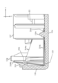
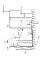
- the first case 11 has a substantially rectangular parallelepiped outer shape. As shown in FIGS. 2 and 3, the first case 11 has an upper surface portion 11a, a first left side surface portion 11b, a first right side surface portion 11c, a first front surface portion 11d, and a first rear surface portion 11e. The first case 11 holds the first antenna 31 , the first substrate 33 and the first cable 35 .
- the first right side surface portion 11 c extends downward in the z direction from the right end of the upper surface portion 11 a and forms the right side surface of the first case 11 .
- a first claw 11n for attaching the twelfth element 312 and the fourteenth element 314 is provided on the inner surface of the first right side surface portion 11c.
- the first mounting guide portion 11g is provided near the center of the first left side surface 11b in the x direction and near the center of the first right side surface 11c in the x direction.
- a first mounting guide portion 11g provided near the first left side surface 11b protrudes downward in the z direction from the first left side surface 11b.
- a first attachment guide portion 11g provided near the first left side portion 11b is fitted with a second attachment guide portion 12g provided near the second left side portion 12b of the second case 12 .
- the first mounting guide portion 11g provided in the vicinity of the first right side portion 11c protrudes downward in the z direction from the first right side portion 11c.
- a first mounting guide portion 11g provided near the first right side surface portion 11c is fitted with a second mounting guide portion 12g provided near the second right side surface portion 12c of the second case 12 .
- the first cable holding portion 11i is provided at a position closer to the first left side portion 11b than the first holding portion receiving area 11j.
- the first cable holding portion 11i and the first holding portion receiving area 11j are configured to be adjacent in the y-direction and positioned at approximately the same height in the z-direction.
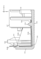
- a first inclined region 11k for temporarily housing the eleventh upper portion 311c of the eleventh element 311 is provided on the front side of the left end portion of the lower surface of the upper surface portion 11a.
- the inclination such that the depression in the z direction becomes larger as it approaches the first left side surface portion 11b (for example, the thickness of the upper surface portion 11a in the z direction becomes thinner). slope) is formed.
- a first inclined region 11k for temporarily accommodating the twelfth upper portion 312c of the twelfth element 312 is provided on the front side of the right end portion of the lower surface of the upper surface portion 11a (see FIG. 3).
- a first claw 11n for insertion into a first claw hole 31b provided in the eleventh side portion 311b of the eleventh element 311 is provided on the front side in the x direction of the first left side surface portion 11b (see FIG. 3).
- a first pawl 11n for insertion into a first pawl hole 31b provided in the thirteenth side portion 313b of the thirteenth element 313 is provided on the rear side in the x direction of the first left side portion 11b.
- a first claw 11n for insertion into a first claw hole 31b provided in the twelfth side portion 312b of the twelfth element 312 is provided on the front side in the x direction of the first right side portion 11c (not shown).
- a first claw 11n for insertion into a first claw hole 31b provided in the fourteenth side portion 314b of the fourteenth element 314 is provided on the rear side in the x direction of the first right side surface portion 11c ( 6 to 9).
- the second mounting guide portion 12g is provided near the center of the second left side surface 12b in the x direction and near the center of the second right side surface 12c in the x direction (see FIGS. 10 to 12).
- a second mounting guide portion 12g provided in the vicinity of the second left side surface 12b protrudes upward in the z direction from the second left side surface 12b.
- a second mounting guide portion 12g provided near the second left side surface portion 12b is fitted with a first mounting guide portion 11g provided near the first left side surface portion 11b of the first case 11 .
- a second mounting guide portion 12g provided near the second right side portion 12c protrudes upward in the z direction from the second right side portion 12c.
- a second mounting guide portion 12g provided near the second right side surface portion 12c is fitted with a first mounting guide portion 11g provided near the first right side surface portion 11c of the first case 11 (see FIG. 4). .
- the second holding portion receiving area 12j has a notch into which the first cable holding portion 11i of the first front surface portion 11d of the first case 11 is fitted.
- a second inclined region 12k for temporarily accommodating the 21st lower portion 321c of the 21st element 321 is provided on the front side of the left end portion of the upper surface of the lower surface portion 12a.
- an inclination such that the depression in the z direction increases as it approaches the second front surface portion 12d (for example, the thickness of the lower surface portion 12a in the z direction is thin). slope) is formed.
- a second inclined region 12k for temporarily accommodating the 22nd lower portion 322c of the 22nd element 322 is provided on the front side of the right end portion of the upper surface of the lower surface portion 12a.
- the base end portion of the eleventh upper portion 311c is connected to the upper end portion of the eleventh side portion 311b and has a surface perpendicular to the z-direction.
- the eleventh top portion 311c extends from the top end of the eleventh side portion 311b in the y-direction and toward the twelfth element 312 .
- the eleventh element 311 is configured such that the tip region (the region away from the first substrate 33) is wider than the base end region (the region near the first substrate 33).
- a first claw hole 31b is provided in the thirteenth side portion 313b.
- a first pin hole 31a is provided in the thirteenth upper portion 313c.
- the 22nd element 322 is attached to the lower surface portion 12a and the second front surface portion 12d of the second case 12 in the following manner.
- a second pin 12m corresponding to the 22nd lower portion 322c is fitted into the second pin hole 32a of the 22nd lower portion 322c.
- a connection region of the 22nd lower portion 322c with the 22nd side portion 322b is pushed downward in the z-direction into the second inclined region 12k corresponding to the 22nd lower portion 322c. Therefore, the 22nd lower portion 322c is temporarily in a tilted state that is not parallel to the xy plane.
- the 22nd element 322 is bent so that the rear end of the 22nd lower portion 322c in the x-direction and the upper end of the 22nd side portion 322b in the z-direction approach each other.
- the angle formed by the 22nd side portion 322b is smaller than the vertical.
- the second claws 12n of the second front surface portion 12d corresponding to the twenty-second side portion 322b are fitted into the second claw holes 32b of the twenty-second side portion 322b. Thereafter, the 22nd side portion 322b is lifted upward in the z direction, and the state in which the connection region of the 22nd lower portion 322c with the 22nd side portion 322b is pushed into the second inclined region 12k is resolved.
- the twenty-third side portion 323b extends in the y-direction and in a direction away from the twenty-fourth element 324 from the distal end portion of the twenty-third arm portion 323a.
- the base end of the 23rd lower portion 323c is connected to the lower end of the 23rd side portion 323b and has a surface perpendicular to the z-direction.
- the twenty-third lower portion 323 c extends from the lower end of the twenty-third side portion 323 b in the x-direction and in a direction approaching the twenty-first element 321 .
- the twenty-third element 323 is configured such that the tip region (the region away from the second substrate 34) is wider than the base end region (the region near the second substrate 34).
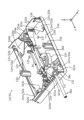
- the first antenna 31 is held by the first case 11 , and the first main body portion 35 a of the first cable 35 is held between the first cable holding portions 11 i of the first case 11 .
- the second antenna 32 is held by the second case 12 , and the second body portion 36 a of the second cable 36 is held between the second cable holding portions 12 i of the second case 12 . Therefore, the vehicle-mounted antenna device can be mounted simply by overlapping the first case 11 to which the first antenna 31 and the first cable 35 are attached and the second case 12 to which the second antenna 32 and the second cable 36 are attached. 1 can be assembled easily.
- the antenna when the antenna is attached to the case, part of the antenna is pushed into the inclined region, and the hook of the case and the element can be easily hooked while canceling the pushed state. Therefore, the antenna can be fixed to the case without using screws, and the influence of screws on electrical performance can be minimized.
Landscapes
- Engineering & Computer Science (AREA)
- Remote Sensing (AREA)
- Microelectronics & Electronic Packaging (AREA)
- Fittings On The Vehicle Exterior For Carrying Loads, And Devices For Holding Or Mounting Articles (AREA)
Priority Applications (2)
| Application Number | Priority Date | Filing Date | Title |
|---|---|---|---|
| US18/692,188 US20240388012A1 (en) | 2021-09-30 | 2022-08-30 | Vehicular antenna device |
| JP2023550475A JPWO2023053818A1 (https=) | 2021-09-30 | 2022-08-30 |
Applications Claiming Priority (2)
| Application Number | Priority Date | Filing Date | Title |
|---|---|---|---|
| JP2021-162413 | 2021-09-30 | ||
| JP2021162413 | 2021-09-30 |
Publications (1)
| Publication Number | Publication Date |
|---|---|
| WO2023053818A1 true WO2023053818A1 (ja) | 2023-04-06 |
Family
ID=84555994
Family Applications (1)
| Application Number | Title | Priority Date | Filing Date |
|---|---|---|---|
| PCT/JP2022/032497 Ceased WO2023053818A1 (ja) | 2021-09-30 | 2022-08-30 | 車載用アンテナ装置 |
Country Status (4)
| Country | Link |
|---|---|
| US (1) | US20240388012A1 (https=) |
| JP (1) | JPWO2023053818A1 (https=) |
| CN (2) | CN115911849A (https=) |
| WO (1) | WO2023053818A1 (https=) |
Cited By (1)
| Publication number | Priority date | Publication date | Assignee | Title |
|---|---|---|---|---|
| US20260005424A1 (en) * | 2024-06-26 | 2026-01-01 | Gopro, Inc. | Antenna system for an electronic device having a metal housing |
Citations (2)
| Publication number | Priority date | Publication date | Assignee | Title |
|---|---|---|---|---|
| JP2008271271A (ja) * | 2007-04-23 | 2008-11-06 | Yokowo Co Ltd | アンテナのケーブル引き出し構造 |
| WO2020027156A1 (ja) * | 2018-07-31 | 2020-02-06 | 株式会社ヨコオ | アンテナ装置 |
Family Cites Families (6)
| Publication number | Priority date | Publication date | Assignee | Title |
|---|---|---|---|---|
| US6191751B1 (en) * | 1998-05-01 | 2001-02-20 | Rangestar Wireless, Inc. | Directional antenna assembly for vehicular use |
| JP2003318623A (ja) * | 2002-02-21 | 2003-11-07 | Toyota Motor Corp | 車両用アンテナ装置 |
| JP5380569B2 (ja) * | 2012-03-30 | 2014-01-08 | 株式会社東芝 | アンテナ装置とこのアンテナ装置を備えた電子機器 |
| US10707553B2 (en) * | 2016-05-06 | 2020-07-07 | GM Global Technology Operations LLC | CPW-fed modified sleeve monopole for GPS, GLONASS, and SDARS bands |
| US10581141B2 (en) * | 2016-10-21 | 2020-03-03 | DISH Technologies L.L.C. | RF antenna arrangement configured to be a part of a lid to an apparatus |
| JP7785078B2 (ja) * | 2021-06-28 | 2025-12-12 | 株式会社ヨコオ | アンテナ装置 |
-
2022
- 2022-08-30 CN CN202211060173.3A patent/CN115911849A/zh active Pending
- 2022-08-30 WO PCT/JP2022/032497 patent/WO2023053818A1/ja not_active Ceased
- 2022-08-30 CN CN202222287095.2U patent/CN218160818U/zh active Active
- 2022-08-30 US US18/692,188 patent/US20240388012A1/en active Pending
- 2022-08-30 JP JP2023550475A patent/JPWO2023053818A1/ja active Pending
Patent Citations (2)
| Publication number | Priority date | Publication date | Assignee | Title |
|---|---|---|---|---|
| JP2008271271A (ja) * | 2007-04-23 | 2008-11-06 | Yokowo Co Ltd | アンテナのケーブル引き出し構造 |
| WO2020027156A1 (ja) * | 2018-07-31 | 2020-02-06 | 株式会社ヨコオ | アンテナ装置 |
Cited By (2)
| Publication number | Priority date | Publication date | Assignee | Title |
|---|---|---|---|---|
| US20260005424A1 (en) * | 2024-06-26 | 2026-01-01 | Gopro, Inc. | Antenna system for an electronic device having a metal housing |
| US12555890B2 (en) * | 2024-06-26 | 2026-02-17 | Gopro, Inc. | Antenna system for an electronic device having a metal housing |
Also Published As
| Publication number | Publication date |
|---|---|
| JPWO2023053818A1 (https=) | 2023-04-06 |
| US20240388012A1 (en) | 2024-11-21 |
| CN115911849A (zh) | 2023-04-04 |
| CN218160818U (zh) | 2022-12-27 |
Similar Documents
| Publication | Publication Date | Title |
|---|---|---|
| EP2749778B1 (en) | Clip | |
| US11437752B2 (en) | Connector | |
| US20230369813A1 (en) | Connection structure | |
| CN112582949B (zh) | 夹持件及线束 | |
| US10122103B2 (en) | Board connector | |
| WO2023053818A1 (ja) | 車載用アンテナ装置 | |
| CN107431313B (zh) | 连接器及屏蔽罩 | |
| CN102365569B (zh) | 光连接器 | |
| JP5585777B2 (ja) | 電気接続箱 | |
| CN113937536B (zh) | 连接器设备 | |
| JP7014424B2 (ja) | コネクタ固定具 | |
| GB2453043A (en) | Arrangement for mounting an ultrasonic sensor to a vehicle bumper | |
| JP5511566B2 (ja) | 表示パネル装置の固定構造 | |
| JP7615782B2 (ja) | プロテクタ | |
| CN111252015A (zh) | 线束 | |
| JP6709682B2 (ja) | アース端子の取付構造、及び、電線収容体 | |
| JP6581820B2 (ja) | 電気接続箱、接続箱本体および保護部材 | |
| CN114746309A (zh) | 连接器保持体及线束 | |
| CN115513860A (zh) | 线束及线束系统 | |
| JP7142330B2 (ja) | コネクタ用カバーおよび車載装置 | |
| JP2018050390A (ja) | バンドクリップ | |
| US20240120691A1 (en) | Connector fixing structure and electrical connection box | |
| CN111845588A (zh) | 安装结构、线束以及支承部件 | |
| JP5156683B2 (ja) | 電流センサの取り付け構造、及びブラケット | |
| JP5948978B2 (ja) | センサ用コネクタ |
Legal Events
| Date | Code | Title | Description |
|---|---|---|---|
| 121 | Ep: the epo has been informed by wipo that ep was designated in this application |
Ref document number: 22875690 Country of ref document: EP Kind code of ref document: A1 |
|
| WWE | Wipo information: entry into national phase |
Ref document number: 2023550475 Country of ref document: JP |
|
| WWE | Wipo information: entry into national phase |
Ref document number: 18692188 Country of ref document: US |
|
| NENP | Non-entry into the national phase |
Ref country code: DE |
|
| 122 | Ep: pct application non-entry in european phase |
Ref document number: 22875690 Country of ref document: EP Kind code of ref document: A1 |