WO2023053582A1 - 二次電池用正極、及びそれを用いた二次電池 - Google Patents
二次電池用正極、及びそれを用いた二次電池 Download PDFInfo
- Publication number
- WO2023053582A1 WO2023053582A1 PCT/JP2022/022947 JP2022022947W WO2023053582A1 WO 2023053582 A1 WO2023053582 A1 WO 2023053582A1 JP 2022022947 W JP2022022947 W JP 2022022947W WO 2023053582 A1 WO2023053582 A1 WO 2023053582A1
- Authority
- WO
- WIPO (PCT)
- Prior art keywords
- positive electrode
- secondary battery
- electrode active
- active materials
- mixture layer
- Prior art date
- Legal status (The legal status is an assumption and is not a legal conclusion. Google has not performed a legal analysis and makes no representation as to the accuracy of the status listed.)
- Ceased
Links
Images

Classifications
-
- H—ELECTRICITY
- H01—ELECTRIC ELEMENTS
- H01M—PROCESSES OR MEANS, e.g. BATTERIES, FOR THE DIRECT CONVERSION OF CHEMICAL ENERGY INTO ELECTRICAL ENERGY
- H01M4/00—Electrodes
- H01M4/02—Electrodes composed of, or comprising, active material
- H01M4/13—Electrodes for accumulators with non-aqueous electrolyte, e.g. for lithium-accumulators; Processes of manufacture thereof
-
- H—ELECTRICITY
- H01—ELECTRIC ELEMENTS
- H01M—PROCESSES OR MEANS, e.g. BATTERIES, FOR THE DIRECT CONVERSION OF CHEMICAL ENERGY INTO ELECTRICAL ENERGY
- H01M4/00—Electrodes
- H01M4/02—Electrodes composed of, or comprising, active material
- H01M4/36—Selection of substances as active materials, active masses, active liquids
- H01M4/362—Composites
- H01M4/364—Composites as mixtures
-
- H—ELECTRICITY
- H01—ELECTRIC ELEMENTS
- H01M—PROCESSES OR MEANS, e.g. BATTERIES, FOR THE DIRECT CONVERSION OF CHEMICAL ENERGY INTO ELECTRICAL ENERGY
- H01M4/00—Electrodes
- H01M4/02—Electrodes composed of, or comprising, active material
- H01M4/13—Electrodes for accumulators with non-aqueous electrolyte, e.g. for lithium-accumulators; Processes of manufacture thereof
- H01M4/131—Electrodes based on mixed oxides or hydroxides, or on mixtures of oxides or hydroxides, e.g. LiCoOx
-
- H—ELECTRICITY
- H01—ELECTRIC ELEMENTS
- H01M—PROCESSES OR MEANS, e.g. BATTERIES, FOR THE DIRECT CONVERSION OF CHEMICAL ENERGY INTO ELECTRICAL ENERGY
- H01M4/00—Electrodes
- H01M4/02—Electrodes composed of, or comprising, active material
- H01M4/36—Selection of substances as active materials, active masses, active liquids
- H01M4/48—Selection of substances as active materials, active masses, active liquids of inorganic oxides or hydroxides
- H01M4/50—Selection of substances as active materials, active masses, active liquids of inorganic oxides or hydroxides of manganese
- H01M4/505—Selection of substances as active materials, active masses, active liquids of inorganic oxides or hydroxides of manganese of mixed oxides or hydroxides containing manganese for inserting or intercalating light metals, e.g. LiMn2O4 or LiMn2OxFy
-
- H—ELECTRICITY
- H01—ELECTRIC ELEMENTS
- H01M—PROCESSES OR MEANS, e.g. BATTERIES, FOR THE DIRECT CONVERSION OF CHEMICAL ENERGY INTO ELECTRICAL ENERGY
- H01M4/00—Electrodes
- H01M4/02—Electrodes composed of, or comprising, active material
- H01M4/36—Selection of substances as active materials, active masses, active liquids
- H01M4/48—Selection of substances as active materials, active masses, active liquids of inorganic oxides or hydroxides
- H01M4/52—Selection of substances as active materials, active masses, active liquids of inorganic oxides or hydroxides of nickel, cobalt or iron
- H01M4/525—Selection of substances as active materials, active masses, active liquids of inorganic oxides or hydroxides of nickel, cobalt or iron of mixed oxides or hydroxides containing iron, cobalt or nickel for inserting or intercalating light metals, e.g. LiNiO2, LiCoO2 or LiCoOxFy
-
- H—ELECTRICITY
- H01—ELECTRIC ELEMENTS
- H01M—PROCESSES OR MEANS, e.g. BATTERIES, FOR THE DIRECT CONVERSION OF CHEMICAL ENERGY INTO ELECTRICAL ENERGY
- H01M4/00—Electrodes
- H01M4/02—Electrodes composed of, or comprising, active material
- H01M4/62—Selection of inactive substances as ingredients for active masses, e.g. binders, fillers
- H01M4/621—Binders
- H01M4/622—Binders being polymers
-
- H—ELECTRICITY
- H01—ELECTRIC ELEMENTS
- H01M—PROCESSES OR MEANS, e.g. BATTERIES, FOR THE DIRECT CONVERSION OF CHEMICAL ENERGY INTO ELECTRICAL ENERGY
- H01M4/00—Electrodes
- H01M4/02—Electrodes composed of, or comprising, active material
- H01M2004/021—Physical characteristics, e.g. porosity, surface area
-
- H—ELECTRICITY
- H01—ELECTRIC ELEMENTS
- H01M—PROCESSES OR MEANS, e.g. BATTERIES, FOR THE DIRECT CONVERSION OF CHEMICAL ENERGY INTO ELECTRICAL ENERGY
- H01M4/00—Electrodes
- H01M4/02—Electrodes composed of, or comprising, active material
- H01M2004/026—Electrodes composed of, or comprising, active material characterised by the polarity
- H01M2004/028—Positive electrodes
-
- Y—GENERAL TAGGING OF NEW TECHNOLOGICAL DEVELOPMENTS; GENERAL TAGGING OF CROSS-SECTIONAL TECHNOLOGIES SPANNING OVER SEVERAL SECTIONS OF THE IPC; TECHNICAL SUBJECTS COVERED BY FORMER USPC CROSS-REFERENCE ART COLLECTIONS [XRACs] AND DIGESTS
- Y02—TECHNOLOGIES OR APPLICATIONS FOR MITIGATION OR ADAPTATION AGAINST CLIMATE CHANGE
- Y02E—REDUCTION OF GREENHOUSE GAS [GHG] EMISSIONS, RELATED TO ENERGY GENERATION, TRANSMISSION OR DISTRIBUTION
- Y02E60/00—Enabling technologies; Technologies with a potential or indirect contribution to GHG emissions mitigation
- Y02E60/10—Energy storage using batteries
Definitions
- the present disclosure relates to a positive electrode for secondary batteries and secondary batteries using the same.
- Electrodes of non-aqueous electrolyte secondary batteries generally have a metal current collector and a mixture layer formed on the surface of the current collector.
- the mixture layer contains, in addition to the active material that is the main component, a conductive agent that forms a conductive path by being interposed between the active materials.
- Patent Literature 1 discloses a technique of including a clay mineral in a negative electrode mixture layer for the purpose of improving the wettability of the electrolytic solution to the negative electrode.
- An object of the present disclosure is to provide a high-density positive electrode capable of suppressing battery resistance, and a secondary battery using the positive electrode.
- a positive electrode for a secondary battery which is one aspect of the present disclosure, includes a positive electrode current collector and a positive electrode mixture layer provided on the surface of the positive electrode current collector, and the positive electrode mixture layer includes n types (n is an integer of 2 or more) and a low-hardness compound having a lower hardness than any of the n types of positive-electrode active materials, and the content of the low-hardness compound in the positive electrode mixture layer is 100 parts by mass. is more than 0.05 parts by mass and less than 1.00 parts by mass with respect to the positive electrode active material.
- a secondary battery according to one aspect of the present disclosure includes the above-described secondary battery positive electrode, a separator, a secondary battery negative electrode facing the secondary battery positive electrode with the separator interposed therebetween, and an electrolyte.
- the positive electrode for secondary batteries according to the present disclosure has a high-density positive electrode mixture layer, and can suppress battery resistance.
- a secondary battery according to the present disclosure has excellent battery characteristics.
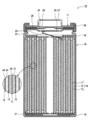
- FIG. 1 is a cross-sectional view of a non-aqueous electrolyte secondary battery that is an example of an embodiment
- FIG. FIG. 5 is a diagram showing the relationship between the packing density of the positive electrode material mixture layer and the elongation of the positive electrode during rolling.
- the positive electrode mixture layer contains two or more types of positive electrode active materials and a low-hardness compound lower in hardness than any of these positive electrode active materials. found that by setting the content of the low-hardness compound in the positive electrode mixture layer within a predetermined range, it is possible to both increase the density of the positive electrode mixture layer and suppress the electrical resistance. Presumably, when the positive electrode is rolled, the existence of the low-hardness compound between the positive electrode active materials facilitates movement of the positive electrode active material, thereby suppressing cracking of the positive electrode active material.
- the positive electrode mixture layer contains n kinds of positive electrode active materials (where n is an integer of 2 or more).
- n is an integer of 2 or more.
- the positive electrode mixture layer contains two or more types of positive electrode active materials having different average particle diameters, the number of contact points between the particles of the positive electrode active material increases, making it more difficult to roll. can be obtained more significantly.
- a cylindrical battery 10 in which a wound electrode body 14 is housed in a bottomed cylindrical outer can 16 will be exemplified, but the outer package is not limited to a cylindrical outer can. (square battery), a coin-shaped exterior can (coin-shaped battery), or an exterior body (laminate battery) composed of a laminate sheet including a metal layer and a resin layer.
- the electrode assembly is not limited to the wound type, and may be a laminated electrode assembly in which a plurality of positive electrodes and a plurality of negative electrodes are alternately laminated with separators interposed therebetween.
- the positive electrode for a secondary battery according to the present disclosure can be applied to an aqueous electrolyte secondary battery using an aqueous electrolyte, but is particularly effective in a nonaqueous electrolyte secondary battery using a nonaqueous electrolyte.
- FIG. 1 is a cross-sectional view of a cylindrical battery 10 that is an example of an embodiment.
- a cylindrical battery 10 includes a wound electrode body 14, a non-aqueous electrolyte, and an outer can 16 containing the electrode body 14 and the non-aqueous electrolyte.
- the electrode body 14 has a positive electrode 11, a negative electrode 12, and a separator 13, and has a wound structure in which the positive electrode 11 and the negative electrode 12 are spirally wound with the separator 13 interposed therebetween.
- the outer can 16 is a bottomed cylindrical metal container that is open on one side in the axial direction.
- the side of the sealing member 17 of the battery will be referred to as the upper side
- the bottom side of the outer can 16 will be referred to as the lower side.
- the non-aqueous electrolyte contains a non-aqueous solvent and an electrolyte salt dissolved in the non-aqueous solvent.
- non-aqueous solvents include esters, ethers, nitriles, amides, and mixed solvents of two or more thereof.
- the non-aqueous solvent may contain a halogen-substituted product obtained by substituting at least part of the hydrogen atoms of these solvents with halogen atoms such as fluorine.
- non-aqueous solvents include ethylene carbonate (EC), ethylmethyl carbonate (EMC), dimethyl carbonate (DMC), mixed solvents thereof, and the like.
- a lithium salt such as LiPF 6 is used as the electrolyte salt.
- the non-aqueous electrolyte is not limited to a liquid electrolyte, and may be a solid electrolyte.
- the positive electrode 11, the negative electrode 12, and the separator 13, which constitute the electrode assembly 14, are all strip-shaped elongated bodies, and are alternately laminated in the radial direction of the electrode assembly 14 by being spirally wound.
- the negative electrode 12 is formed with a size one size larger than that of the positive electrode 11 in order to prevent deposition of lithium. That is, the negative electrode 12 is formed longer than the positive electrode 11 in the longitudinal direction and the width direction (transverse direction).
- the separator 13 is at least one size larger than the positive electrode 11, and two separators 13 are arranged so as to sandwich the positive electrode 11, for example.
- the electrode body 14 has a positive electrode lead 20 connected to the positive electrode 11 by welding or the like, and a negative electrode lead 21 connected to the negative electrode 12 by welding or the like.
- Insulating plates 18 and 19 are arranged above and below the electrode body 14, respectively.
- the positive electrode lead 20 extends through the through hole of the insulating plate 18 toward the sealing member 17
- the negative electrode lead 21 extends through the outside of the insulating plate 19 toward the bottom of the outer can 16 .
- the positive electrode lead 20 is connected to the lower surface of the internal terminal plate 23 of the sealing body 17 by welding or the like, and the cap 27, which is the top plate of the sealing body 17 electrically connected to the internal terminal plate 23, serves as the positive electrode terminal.
- the negative electrode lead 21 is connected to the inner surface of the bottom of the outer can 16 by welding or the like, and the outer can 16 serves as a negative electrode terminal.
- a gasket 28 is provided between the outer can 16 and the sealing body 17 to ensure hermeticity inside the battery.
- the outer can 16 is formed with a grooved portion 22 that supports the sealing member 17 and has a portion of the side surface projecting inward.
- the grooved portion 22 is preferably annularly formed along the circumferential direction of the outer can 16 and supports the sealing member 17 on its upper surface.
- the sealing member 17 is fixed to the upper portion of the outer can 16 by the grooved portion 22 and the open end of the outer can 16 that is crimped to the sealing member 17 .
- the sealing body 17 has a structure in which an internal terminal plate 23, a lower valve body 24, an insulating member 25, an upper valve body 26, and a cap 27 are layered in order from the electrode body 14 side.
- Each member constituting the sealing member 17 has, for example, a disk shape or a ring shape, and each member except for the insulating member 25 is electrically connected to each other.
- the lower valve body 24 and the upper valve body 26 are connected at their central portions, and an insulating member 25 is interposed between their peripheral edge portions.
- the positive electrode 11, the negative electrode 12, and the separator 13 that constitute the electrode body 14, particularly the positive electrode 11, will be described in detail below.
- the positive electrode 11 has a positive electrode current collector 30 and a positive electrode mixture layer 31 provided on the surface of the positive electrode current collector 30 .
- a foil of a metal such as aluminum or an aluminum alloy that is stable in the potential range of the positive electrode 11, a film in which the metal is arranged on the surface layer, or the like can be used.
- the positive electrode mixture layers 31 are preferably provided on both sides of the positive electrode current collector 30 .
- the positive electrode mixture layer 31 contains n types (n is an integer of 2 or more) of positive electrode active materials and a low-hardness compound lower in hardness than any of the n types of positive electrode active materials. This makes it possible to obtain a high-density positive electrode capable of suppressing battery resistance.
- An index for classifying the positive electrode active material into n types is, for example, the average particle size. That is, the average particle size of the n kinds of positive electrode active materials may be two or more kinds.
- the average particle diameter means a volume-based median diameter (D50). D50 means a particle size at which the cumulative frequency is 50% from the smaller particle size in the volume-based particle size distribution, and is also called median diameter.
- the particle size distribution of the positive electrode active material can be measured using a laser diffraction particle size distribution analyzer (eg MT3000II manufactured by Microtrack Bell Co., Ltd.) using water as a dispersion medium.
- the minimum average particle size D min of the n types of positive electrode active materials may be 0.1 ⁇ m to 10 ⁇ m, and the maximum average particle size D max of the n types of positive electrode active materials is at least twice D min . may This improves the packing density of the positive electrode mixture layer.
- the upper limit of Dmax is, for example, 10 times Dmin .
- the positive electrode active material is composed of two types of particles having different average particle diameters, the average particle diameter D min of small particles is 0.1 ⁇ m to 10 ⁇ m, the average particle diameter D max of large particles is 10 ⁇ m to 30 ⁇ m, and 2 ⁇ 2 D max /D min ⁇ 10 can be set.
- At least one of the n kinds of positive electrode active materials may consist of one primary particle or a secondary particle formed by agglomeration of 2 to 5 primary particles. It is preferred that the smaller particles are particles with fewer such agglomerated primary particles.
- the type of positive electrode active material having D min may be particles with less such agglomerated primary particles.
- An index for classifying positive electrode active materials into n types is, for example, the composition. That is, the composition of the n types of positive electrode active materials may be two or more types.
- the positive electrode active material is, for example, a lithium-containing transition metal composite oxide. Elements contained in the lithium-containing transition metal composite oxide include Ni, Co, Mn, Na, K, Mg, Ca, Sr, Ba, Sc, Y, La, Ce, Pr, Nd, Sm, Eu, Gd.
- the lithium-containing transition metal composite oxide preferably contains Ni.
- a preferred example of the lithium-containing transition metal composite oxide has a layered rock salt crystal structure and has the general formula: LiNi x M 1-x O 2 (wherein M is selected from the group consisting of Al, Mn and Co and at least one compound oxide represented by 0.3 ⁇ x ⁇ 1.0).
- Composite oxides with a high Ni content are effective in increasing the capacity of batteries.
- the composition of the composite oxide can be measured using an ICP emission spectrometer (iCAP6300 manufactured by Thermo Fisher Scientific) or the like.
- At least one of the n kinds of positive electrode active materials may contain Mn.
- an NCM-based lithium-containing transition metal composite oxide containing Ni, Co, and Mn is harder than an NCA-based lithium-containing transition metal composite oxide containing Ni, Co, and Al. The effect of the compound is more pronounced.
- the content of the low-hardness compound in the positive electrode mixture layer is more than 0.05 parts by mass and less than 1.00 parts by mass with respect to 100 parts by mass of the positive electrode active material. When the content of the low-hardness compound is 0.05 parts by mass or less, the effect of the low-hardness compound is not exhibited. When the content of the low-hardness compound is 1.00 parts by mass or more, the presence of the low-hardness compound reduces the number of conductive paths and increases the electrical resistance. That is, the electrical resistance can be suppressed by including the low-hardness compound in the positive electrode mixture layer at a predetermined ratio.
- the content of the low hardness compound in the positive electrode mixture layer is preferably 0.06 parts by mass to 0.99 parts by mass, more preferably 0.08 parts by mass to 0.50 parts by mass, with respect to 100 parts by mass of the positive electrode active material. more preferred.
- the Mohs hardness of the low-hardness compound contained in the positive electrode mixture layer 31 is preferably 3 or less. If the Mohs hardness of the low-hardness compound is 3 or less, cracking of the positive electrode active material during rolling can be further suppressed.
- a low hardness compound is, for example, talc.
- Talc has a Mohs hardness of 1 and is the softest mineral among inorganic minerals.
- the composition of talc can be expressed as Mg 3 Si 4 O 10 (OH) 2 .
- the average particle size of the low-hardness compound before being mixed with the positive electrode active material is, for example, 0.1 ⁇ m to 5.0 ⁇ m, preferably 0.3 ⁇ m to 3.0 ⁇ m. Yes, more preferably 0.5 ⁇ m to 2.0 ⁇ m.
- the average particle size of the low hardness compound after being mixed with the positive electrode active material may be smaller than the above value.
- the positive electrode mixture layer 31 may further contain a conductive agent.
- the conductive agent forms a conductive path in the positive electrode mixture layer 31 and suppresses electrical resistance.
- Examples of conductive agents include carbon-based particles such as carbon black (CB), acetylene black (AB), ketjen black, carbon nanotubes (CNT), graphene, and graphite. These may be used alone or in combination of two or more.
- the content of the conductive agent is, for example, 0.1% by mass to 5.0% by mass with respect to 100 parts by mass of the positive electrode active material.
- the positive electrode mixture layer 31 may further contain a binder.
- binders include fluorine resins such as polytetrafluoroethylene (PTFE) and polyvinylidene fluoride (PVdF), polyacrylonitrile (PAN), polyimide, acrylic resins, and polyolefins. These resins may be used in combination with cellulose derivatives such as carboxymethyl cellulose (CMC) or salts thereof, polyethylene oxide (PEO), and the like.
- the content of the binder is, for example, 0.1% by mass to 5.0% by mass with respect to 100 parts by mass of the positive electrode active material.
- the positive electrode 11 is formed, for example, by coating a positive electrode mixture slurry on the positive electrode current collector 30, drying the coating film, and then rolling to form the positive electrode mixture layers 31 on both surfaces of the positive electrode current collector 30. can be made.
- the positive electrode mixture slurry contains, for example, a positive electrode active material, a low hardness compound, a conductive agent, and a binder.
- the dispersion medium for the positive electrode mixture slurry is not particularly limited, but one example is N-methyl-2-pyrrolidone (NMP).
- NMP N-methyl-2-pyrrolidone
- the low-hardness compound may be mixed with the positive electrode active material in a mixer or the like before being mixed with other components. Thereby, the low-hardness compound can be interposed between the positive electrode active materials.
- the positive electrode mixture layer 31 (this embodiment) containing a low-hardness compound can have a higher packing density than a positive electrode mixture layer (reference) that does not contain a low-hardness compound.
- FIG. 2 is a diagram showing the relationship between the filling density of the positive electrode mixture layer 31 and the elongation of the positive electrode 11 during rolling.
- the packing density can be increased without stretching the positive electrode up to a predetermined density.
- the packing density does not become higher than the maximum packing density a, and the positive electrode only extends.
- the packing density is higher than the reference when the packing density becomes difficult to increase even if the linear pressure is increased, and the maximum packing density b is higher than the maximum packing density a.
- the lowest linear pressure at which the maximum packing density is obtained is referred to as the lowest packing linear pressure.
- the negative electrode 12 has a negative electrode current collector 40 and a negative electrode mixture layer 41 provided on the surface of the negative electrode current collector 40 .
- a foil of a metal such as copper that is stable in the potential range of the negative electrode 12, a film having the metal on the surface layer, or the like can be used.
- the negative electrode mixture layers 41 are preferably provided on both sides of the negative electrode current collector 40 .
- a negative electrode mixture slurry is applied onto the negative electrode current collector 40 , the coating film is dried, and then rolled to form the negative electrode mixture layers 41 on both sides of the negative electrode current collector 40 .
- the negative electrode mixture layer 41 contains, for example, a negative electrode active material and a binder.
- the negative electrode active material contained in the negative electrode mixture layer 41 includes, for example, a carbon-based active material that reversibly absorbs and releases lithium ions.
- Suitable carbon-based active materials are graphite such as natural graphite such as flake graphite, massive graphite and earthy graphite, artificial graphite such as massive artificial graphite (MAG) and graphitized mesophase carbon microbeads (MCMB).
- a Si-based active material composed of at least one of Si and a Si-containing compound may be used as the negative electrode active material, or a carbon-based active material and a Si-based active material may be used in combination.
- the binder contained in the negative electrode mixture layer 41 as in the case of the positive electrode 11, fluorine resin, PAN, polyimide, acrylic resin, polyolefin, or the like can be used, but styrene-butadiene rubber (SBR) is also usable. It is preferable to use Moreover, the negative electrode mixture layer 41 preferably further contains CMC or its salt, polyacrylic acid (PAA) or its salt, polyvinyl alcohol (PVA), or the like. Among them, it is preferable to use SBR together with CMC or its salt or PAA or its salt. Note that the negative electrode mixture layer 41 may contain a conductive agent.
- a porous sheet having ion permeability and insulation is used for the separator 13 .
- porous sheets include microporous thin films, woven fabrics, and non-woven fabrics.
- Suitable materials for the separator 13 include polyolefins such as polyethylene, polypropylene, copolymers of ethylene and ⁇ -olefin, and cellulose.
- the separator 13 may have either a single layer structure or a laminated structure.
- a heat-resistant layer containing inorganic particles, a heat-resistant layer made of a highly heat-resistant resin such as aramid resin, polyimide, polyamideimide, or the like may be formed on the surface of the separator 13 .
- Example 1 [Preparation of positive electrode]
- the positive electrode active material a mixture of two types of lithium-containing transition metal composite oxides having average particle sizes of 17 ⁇ m and 5 ⁇ m at a mass ratio of 50:50 was used.
- the two types of lithium-containing transition metal composite oxides had the same composition, and both were NCM-based.
- Talc having an average particle size of 0.6 ⁇ m was used as the low hardness compound.
- a positive electrode active material and talc were mixed at a mass ratio of 100:0.30 using a mixer to obtain a mixture of these.
- acetylene black (AB), and polyvinylidene fluoride (PVDF) were mixed at a solid content mass ratio of 98.4:0.7:0.9, and N-methyl-2-pyrrolidone was used as a dispersion medium. (NMP) was used to prepare a positive electrode mixture slurry.
- the positive electrode mixture slurry is applied to a positive electrode current collector made of aluminum foil, the coating film is dried, and after rolling at the minimum filling line pressure separately measured in advance, the positive electrode is cut into a predetermined electrode size. got
- Ethylene carbonate (EC), ethyl methyl carbonate (EMC) and dimethyl carbonate (DMC) were mixed in a volume ratio of 20:5:75.
- a non-aqueous electrolyte was prepared by dissolving lithium hexafluorophosphate (LiPF 6 ) in the mixed solvent at a concentration of 1.35 mol/liter.
- test cell An electrode body was constructed by arranging the positive electrode and the negative electrode made of lithium metal foil in opposition to each other with a separator interposed therebetween, and the electrode body and the non-aqueous electrolyte were accommodated in an exterior body constructed using an aluminum laminate sheet. After that, the opening of the outer package was sealed to obtain a test cell (non-aqueous electrolyte secondary battery).
- DCIR direct current resistance
- Examples 2 to 4 Comparative Examples 1 to 3> A test cell was produced and evaluated in the same manner as in Example 1, except that the average particle size and amount of talc used in producing the positive electrode were changed as shown in Table 1. Table 1 shows the DCIR evaluation results of Examples 1 to 4 and Comparative Examples 1 to 3. For the minimum filling line pressure, the one measured for each of the examples and the comparative examples was used.
- Example 5 Using talc with an average particle size of 1.0 ⁇ m, the positive electrode active material and talc are mixed at a mass ratio of 100:0.10 using a mixer to obtain a mixture of these, and this mixture, AB, and CNT and PVDF were mixed at a solid content mass ratio of 98.0: 0.7: 0.4: 0.9. A test cell was prepared and evaluated in the same manner as in Example 1. .
- Example 6 Comparative Examples 4 to 6> A test cell was produced and evaluated in the same manner as in Example 1, except that the average particle size and amount of talc used in producing the positive electrode were changed as shown in Table 2.
- Table 2 shows the DCIR evaluation results of Examples 5 and 6 and Comparative Examples 4-6. For the minimum filling line pressure, the one measured for each of the examples and the comparative examples was used.
Landscapes
- Chemical & Material Sciences (AREA)
- Chemical Kinetics & Catalysis (AREA)
- Electrochemistry (AREA)
- General Chemical & Material Sciences (AREA)
- Inorganic Chemistry (AREA)
- Composite Materials (AREA)
- Engineering & Computer Science (AREA)
- Materials Engineering (AREA)
- Battery Electrode And Active Subsutance (AREA)
Priority Applications (4)
| Application Number | Priority Date | Filing Date | Title |
|---|---|---|---|
| CN202280063852.8A CN118043983A (zh) | 2021-09-30 | 2022-06-07 | 二次电池用正极和使用其的二次电池 |
| JP2023551065A JPWO2023053582A1 (https=) | 2021-09-30 | 2022-06-07 | |
| US18/693,312 US20250132310A1 (en) | 2021-09-30 | 2022-06-07 | Positive electrode for secondary battery |
| EP22875461.0A EP4411851A4 (en) | 2021-09-30 | 2022-06-07 | POSITIVE ELECTRODE FOR SECONDARY BATTERY |
Applications Claiming Priority (2)
| Application Number | Priority Date | Filing Date | Title |
|---|---|---|---|
| JP2021-160852 | 2021-09-30 | ||
| JP2021160852 | 2021-09-30 |
Publications (1)
| Publication Number | Publication Date |
|---|---|
| WO2023053582A1 true WO2023053582A1 (ja) | 2023-04-06 |
Family
ID=85782216
Family Applications (1)
| Application Number | Title | Priority Date | Filing Date |
|---|---|---|---|
| PCT/JP2022/022947 Ceased WO2023053582A1 (ja) | 2021-09-30 | 2022-06-07 | 二次電池用正極、及びそれを用いた二次電池 |
Country Status (5)
| Country | Link |
|---|---|
| US (1) | US20250132310A1 (https=) |
| EP (1) | EP4411851A4 (https=) |
| JP (1) | JPWO2023053582A1 (https=) |
| CN (1) | CN118043983A (https=) |
| WO (1) | WO2023053582A1 (https=) |
Citations (5)
| Publication number | Priority date | Publication date | Assignee | Title |
|---|---|---|---|---|
| JP2001266855A (ja) * | 2000-03-23 | 2001-09-28 | Matsushita Battery Industrial Co Ltd | 非水電解質二次電池用電極の製造法および非水電解質二次電池 |
| JP2004134236A (ja) * | 2002-10-10 | 2004-04-30 | Japan Storage Battery Co Ltd | 非水系二次電池 |
| JP2008071757A (ja) | 2006-09-11 | 2008-03-27 | Lg Chem Ltd | 粘土鉱物を含む電極合剤及びこれを用いた電気化学セル |
| JP2008262859A (ja) * | 2007-04-13 | 2008-10-30 | Toyota Central R&D Labs Inc | 非水電解液及びリチウムイオン二次電池 |
| JP2009110942A (ja) * | 2007-10-10 | 2009-05-21 | Hitachi Maxell Ltd | 非水二次電池およびこれを用いた機器 |
Family Cites Families (6)
| Publication number | Priority date | Publication date | Assignee | Title |
|---|---|---|---|---|
| KR100670507B1 (ko) * | 2005-04-28 | 2007-01-16 | 삼성에스디아이 주식회사 | 리튬 이차 전지 |
| JP2017027768A (ja) * | 2015-07-22 | 2017-02-02 | コニカミノルタ株式会社 | スラリー状組成物およびリチウムイオン2次電池の正極の製造方法 |
| CN117457872A (zh) * | 2018-02-07 | 2024-01-26 | 宁德新能源科技有限公司 | 正极活性材料和锂离子电池 |
| KR102453273B1 (ko) * | 2018-05-23 | 2022-10-11 | 주식회사 엘지에너지솔루션 | 리튬 이차전지용 양극재, 이를 포함하는 리튬 이차전지용 양극 및 리튬 이차전지 |
| WO2021126998A1 (en) * | 2019-12-18 | 2021-06-24 | University Of Washington | Solid-state battery cathodes and methods thereof |
| JP7653632B2 (ja) * | 2020-01-31 | 2025-03-31 | パナソニックIpマネジメント株式会社 | 二次電池用正極および二次電池 |
-
2022
- 2022-06-07 JP JP2023551065A patent/JPWO2023053582A1/ja active Pending
- 2022-06-07 US US18/693,312 patent/US20250132310A1/en active Pending
- 2022-06-07 CN CN202280063852.8A patent/CN118043983A/zh active Pending
- 2022-06-07 EP EP22875461.0A patent/EP4411851A4/en active Pending
- 2022-06-07 WO PCT/JP2022/022947 patent/WO2023053582A1/ja not_active Ceased
Patent Citations (5)
| Publication number | Priority date | Publication date | Assignee | Title |
|---|---|---|---|---|
| JP2001266855A (ja) * | 2000-03-23 | 2001-09-28 | Matsushita Battery Industrial Co Ltd | 非水電解質二次電池用電極の製造法および非水電解質二次電池 |
| JP2004134236A (ja) * | 2002-10-10 | 2004-04-30 | Japan Storage Battery Co Ltd | 非水系二次電池 |
| JP2008071757A (ja) | 2006-09-11 | 2008-03-27 | Lg Chem Ltd | 粘土鉱物を含む電極合剤及びこれを用いた電気化学セル |
| JP2008262859A (ja) * | 2007-04-13 | 2008-10-30 | Toyota Central R&D Labs Inc | 非水電解液及びリチウムイオン二次電池 |
| JP2009110942A (ja) * | 2007-10-10 | 2009-05-21 | Hitachi Maxell Ltd | 非水二次電池およびこれを用いた機器 |
Non-Patent Citations (1)
| Title |
|---|
| See also references of EP4411851A4 |
Also Published As
| Publication number | Publication date |
|---|---|
| EP4411851A1 (en) | 2024-08-07 |
| CN118043983A (zh) | 2024-05-14 |
| EP4411851A4 (en) | 2025-11-12 |
| JPWO2023053582A1 (https=) | 2023-04-06 |
| US20250132310A1 (en) | 2025-04-24 |
Similar Documents
| Publication | Publication Date | Title |
|---|---|---|
| JP7804945B2 (ja) | 非水電解質二次電池 | |
| JP7324119B2 (ja) | 非水電解質二次電池用正極活物質、及び非水電解質二次電池 | |
| JP7317526B2 (ja) | 非水電解質二次電池 | |
| CN113614943B (zh) | 二次电池 | |
| WO2022070898A1 (ja) | 非水電解質二次電池用正極活物質および非水電解質二次電池 | |
| WO2023032445A1 (ja) | 非水電解液二次電池 | |
| US11522188B2 (en) | Positive electrode active material for non-aqueous electrolyte secondary battery, and non-aqueous electrolyte secondary battery | |
| WO2024004577A1 (ja) | 非水電解質二次電池用正極活物質および非水電解質二次電池 | |
| JP7324120B2 (ja) | 非水電解質二次電池用正極活物質、及び非水電解質二次電池 | |
| WO2024004578A1 (ja) | 非水電解質二次電池 | |
| JP7664545B2 (ja) | 非水電解質二次電池用正極活物質および非水電解質二次電池 | |
| JP2025028269A (ja) | 非水電解質二次電池用正極活物質、及び非水電解質二次電池 | |
| WO2024070220A1 (ja) | 非水電解質二次電池 | |
| WO2024070259A1 (ja) | 非水電解質二次電池 | |
| WO2024024507A1 (ja) | 非水電解質二次電池用正極及び非水電解質二次電池 | |
| WO2024042897A1 (ja) | 二次電池用負極および非水電解質二次電池 | |
| WO2024042871A1 (ja) | 非水電解質二次電池 | |
| WO2023032558A1 (ja) | 二次電池用負極および二次電池 | |
| WO2023053582A1 (ja) | 二次電池用正極、及びそれを用いた二次電池 | |
| WO2021241027A1 (ja) | 非水電解質二次電池用正極活物質および非水電解質二次電池 | |
| JP7539392B2 (ja) | 非水電解質二次電池用正極活物質、及び非水電解質二次電池 | |
| US20250015267A1 (en) | Nonaqueous electrolyte secondary battery positive electrode and nonaqueous electrolyte secondary battery | |
| WO2025177969A1 (ja) | 非水電解質二次電池用セパレータおよび非水電解質二次電池 | |
| WO2024042998A1 (ja) | 非水電解質二次電池 | |
| WO2023181912A1 (ja) | 非水電解質二次電池用正極および非水電解質二次電池 |
Legal Events
| Date | Code | Title | Description |
|---|---|---|---|
| 121 | Ep: the epo has been informed by wipo that ep was designated in this application |
Ref document number: 22875461 Country of ref document: EP Kind code of ref document: A1 |
|
| WWE | Wipo information: entry into national phase |
Ref document number: 2023551065 Country of ref document: JP |
|
| WWE | Wipo information: entry into national phase |
Ref document number: 18693312 Country of ref document: US |
|
| WWE | Wipo information: entry into national phase |
Ref document number: 202280063852.8 Country of ref document: CN |
|
| NENP | Non-entry into the national phase |
Ref country code: DE |
|
| ENP | Entry into the national phase |
Ref document number: 2022875461 Country of ref document: EP Effective date: 20240430 |
|
| WWP | Wipo information: published in national office |
Ref document number: 18693312 Country of ref document: US |