WO2023042665A1 - 複合基材及びその製造方法 - Google Patents
複合基材及びその製造方法 Download PDFInfo
- Publication number
- WO2023042665A1 WO2023042665A1 PCT/JP2022/032887 JP2022032887W WO2023042665A1 WO 2023042665 A1 WO2023042665 A1 WO 2023042665A1 JP 2022032887 W JP2022032887 W JP 2022032887W WO 2023042665 A1 WO2023042665 A1 WO 2023042665A1
- Authority
- WO
- WIPO (PCT)
- Prior art keywords
- group
- composite substrate
- pores
- catecholamines
- polymerization
- Prior art date
- Legal status (The legal status is an assumption and is not a legal conclusion. Google has not performed a legal analysis and makes no representation as to the accuracy of the status listed.)
- Ceased
Links
Images








Classifications
-
- B—PERFORMING OPERATIONS; TRANSPORTING
- B32—LAYERED PRODUCTS
- B32B—LAYERED PRODUCTS, i.e. PRODUCTS BUILT-UP OF STRATA OF FLAT OR NON-FLAT, e.g. CELLULAR OR HONEYCOMB, FORM
- B32B27/00—Layered products comprising a layer of synthetic resin
- B32B27/30—Layered products comprising a layer of synthetic resin comprising vinyl (co)polymers; comprising acrylic (co)polymers
-
- B—PERFORMING OPERATIONS; TRANSPORTING
- B32—LAYERED PRODUCTS
- B32B—LAYERED PRODUCTS, i.e. PRODUCTS BUILT-UP OF STRATA OF FLAT OR NON-FLAT, e.g. CELLULAR OR HONEYCOMB, FORM
- B32B5/00—Layered products characterised by the non- homogeneity or physical structure, i.e. comprising a fibrous, filamentary, particulate or foam layer; Layered products characterised by having a layer differing constitutionally or physically in different parts
- B32B5/18—Layered products characterised by the non- homogeneity or physical structure, i.e. comprising a fibrous, filamentary, particulate or foam layer; Layered products characterised by having a layer differing constitutionally or physically in different parts characterised by features of a layer of foamed material
-
- C—CHEMISTRY; METALLURGY
- C08—ORGANIC MACROMOLECULAR COMPOUNDS; THEIR PREPARATION OR CHEMICAL WORKING-UP; COMPOSITIONS BASED THEREON
- C08G—MACROMOLECULAR COMPOUNDS OBTAINED OTHERWISE THAN BY REACTIONS ONLY INVOLVING UNSATURATED CARBON-TO-CARBON BONDS
- C08G61/00—Macromolecular compounds obtained by reactions forming a carbon-to-carbon link in the main chain of the macromolecule
-
- C—CHEMISTRY; METALLURGY
- C09—DYES; PAINTS; POLISHES; NATURAL RESINS; ADHESIVES; COMPOSITIONS NOT OTHERWISE PROVIDED FOR; APPLICATIONS OF MATERIALS NOT OTHERWISE PROVIDED FOR
- C09D—COATING COMPOSITIONS, e.g. PAINTS, VARNISHES OR LACQUERS; FILLING PASTES; CHEMICAL PAINT OR INK REMOVERS; INKS; CORRECTING FLUIDS; WOODSTAINS; PASTES OR SOLIDS FOR COLOURING OR PRINTING; USE OF MATERIALS THEREFOR
- C09D201/00—Coating compositions based on unspecified macromolecular compounds
- C09D201/02—Coating compositions based on unspecified macromolecular compounds characterised by the presence of specified groups, e.g. terminal or pendant functional groups
-
- C—CHEMISTRY; METALLURGY
- C09—DYES; PAINTS; POLISHES; NATURAL RESINS; ADHESIVES; COMPOSITIONS NOT OTHERWISE PROVIDED FOR; APPLICATIONS OF MATERIALS NOT OTHERWISE PROVIDED FOR
- C09D—COATING COMPOSITIONS, e.g. PAINTS, VARNISHES OR LACQUERS; FILLING PASTES; CHEMICAL PAINT OR INK REMOVERS; INKS; CORRECTING FLUIDS; WOODSTAINS; PASTES OR SOLIDS FOR COLOURING OR PRINTING; USE OF MATERIALS THEREFOR
- C09D5/00—Coating compositions, e.g. paints, varnishes or lacquers, characterised by their physical nature or the effects produced; Filling pastes
Definitions
- the present invention relates to a composite base material and a manufacturing method thereof.
- Polymer chains can be introduced, for example, by generating radicals on the surface of the base material and polymerizing the monomer group with the radicals. Radicals can be generated, for example, by irradiating the surface of the substrate with energy rays such as ultraviolet rays, electron rays, gamma rays, or plasma.
- Patent Document 1 discloses a method of introducing polymer chains onto the surface of a substrate without using energy rays or plasma. Specifically, Patent Document 1 discloses that a base layer to which a polymerization initiator is fixed is formed on the surface of a base material, and a polymer film is produced by polymerizing a monomer starting from the polymerization initiator. disclosed. In Patent Document 1, the underlying layer is composed of polydopamine, which is an organic material. According to the method of Patent Literature 1, polymer chains can be easily introduced to the surface of the base material regardless of the type of material of the base material.
- an object of the present invention is to provide a new composite substrate in which the surfaces of the pores of the porous substrate are covered with an underlayer containing an organic material.
- the present invention a porous substrate comprising a first organic material; a base layer covering the surface of the pores of the porous substrate and containing a second organic material; with A composite base material is provided, wherein at least one of (a) the underlayer includes a polymerization initiating group, and (b) the underlayer is bound to a polymer chain.
- a method for manufacturing the above composite base material comprising the step (I) of forming the underlayer containing the polymerization initiation group so as to cover the surface of the pores of the porous substrate.
- FIG. 1 is a schematic cross-sectional view of a composite substrate according to one embodiment of the present invention
- FIG. 1 is a schematic cross-sectional view of a composite substrate according to one embodiment of the present invention
- FIG. 4 is a schematic cross-sectional view of a composite base material according to a modified example of the present invention
- FIG. 4 is a schematic cross-sectional view of a composite base material according to a modified example of the present invention
- 1 is a scanning electron microscope (SEM) image of a cross section near the outer surface of the PTFE porous membrane A used in Examples.
- 1 is an SEM image of a cross section near the center in the thickness direction of the PTFE porous membrane A used in Examples.
- SEM scanning electron microscope
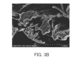
- FIG. 4 is a SEM image of a cross section near the outer surface of the composite substrate of Example 3.
- FIG. 4 is a SEM image of a cross section near the center in the thickness direction of the composite base material of Example 3.
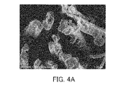
- FIG. 10 is an SEM image of a cross section near the outer surface of the composite substrate of Example 4.
- FIG. 4 is a SEM image of a cross section near the center in the thickness direction of the composite base material of Example 4.
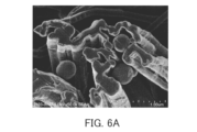
- FIG. 10 is a SEM image of a cross section near the outer surface of the PTFE porous membrane A on which the underlayer of Example 5 was formed.
- FIG. 10 is a SEM image of a cross section near the center in the thickness direction of the PTFE porous membrane A having the underlayer of Example 5 formed thereon.
- FIG. 10 is a SEM image of a cross section near the center in the thickness direction of the PTFE porous membrane A having the underlayer of Example 5 formed thereon.
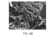
- FIG. 10 is an SEM image of a cross section near the outer surface of the composite substrate of Example 5.
- FIG. 10 is an SEM image of a cross section near the center in the thickness direction of the composite substrate of Example 5.
- FIG. 10 is a graph showing the results of microscopic Raman spectroscopic measurement of the cross section of the PTFE porous membrane A, the cross section of the PTFE porous membrane A having the base layer formed thereon, and the cross section of the composite substrate in Example 5.
- FIG. 1 is an image mapping the peak at 731 cm ⁇ 1 for the cross section of the PTFE porous membrane A used in Example 5, based on the results of microscopic Raman spectroscopy.
- FIG. 1 is an image mapping the peak at 731 cm ⁇ 1 for the cross section of the PTFE porous membrane A used in Example 5, based on the results of microscopic Raman spectroscopy.
- FIG. 10 is an image mapping the peak at 1580 cm ⁇ 1 for the cross section of the PTFE porous membrane A on which the underlayer was formed in Example 5, based on the results of microscopic Raman spectroscopy.
- FIG. 10 is an image mapping the peak at 1580 cm ⁇ 1 for the cross section of the composite substrate of Example 5, based on the results of microscopic Raman spectroscopy.
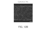
- FIG. 10 is an image mapping the results of time-of-flight secondary ion mass spectrometry (TOF-SIMS) of the cross section of the PTFE porous membrane A on which the underlayer was formed in Example 5.
- TOF-SIMS time-of-flight secondary ion mass spectrometry
- FIG. 10 is an image mapping the results of TOF-SIMS for the cross section of the PTFE porous membrane A on which the underlayer of Example 5 was formed.
- FIG. FIG. 10 is an image mapping the results of TOF-SIMS for the cross section of the PTFE porous membrane A on which the underlayer of Example 5 was formed.
- FIG. FIG. 10 is an image mapping the results of TOF-SIMS for the cross section of the composite substrate of Example 5.
- FIG. 10 is an image mapping the results of TOF-SIMS for the cross section of the composite substrate of Example 5.
- FIG. 10 is an image mapping the results of TOF-SIMS for the cross section of the composite substrate of Example 5.
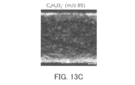
- FIG. 10 is an image mapping the results of TOF-SIMS for the cross section of the composite substrate of Example 5.
- the composite substrate according to the first aspect of the present invention is a porous substrate comprising a first organic material; a base layer covering the surface of the pores of the porous substrate and containing a second organic material; with At least one of (a) the underlying layer includes a polymerization initiation group and (b) the underlying layer is bound to a polymer chain is established.
- the second organic material contains a polymer having structural units derived from catecholamines.
- the polymer contains the polymerization initiation group, and (b1) the polymer is bonded to the polymer chain. At least one of is established.
- the catecholamines are represented by the following formula (1).
- R 1 to R 4 are each independently a hydrogen atom or an optional substituent
- Z is represented by the following formula (2) or (3).
- X - is any anion
- R 5 is a hydrogen atom or an arbitrary substituent.
- the optional substituents in R 1 and R 2 are hydroxyl group, carboxyl group or halogen group.
- Z is represented by the following formula (4).
- R 6 is a divalent hydrocarbon group which may have a substituent
- A is the polymerization initiation group.
- the polymerization initiation group is at least one selected from the group consisting of halogen groups and nitroxide groups. .
- the polymer chain contains a structural unit derived from a radically polymerizable monomer.
- the first organic material contains a hydrophobic resin.
- the first organic material contains a fluororesin.
- the first organic material contains polytetrafluoroethylene.
- the base layer includes a first layer in direct contact with the surface of the hole, a second layer covering the one layer; At least one of (a2) the second layer includes a polymerization initiation group, and (b2) the second layer is bound to a polymer chain is established.
- the method for producing a composite substrate according to the thirteenth aspect of the present invention comprises: A method for manufacturing a composite substrate according to any one of the first to twelfth aspects, comprising: The manufacturing method is The method includes step (I) of forming the underlayer containing the polymerization initiation group so as to cover the surface of the pores of the porous substrate.
- the step (I) includes: step (i) of contacting the surfaces of the pores with a solution containing catecholamines; a step (ii) of allowing the polymerization reaction of the catecholamines to proceed; including.
- the catecholamines contain the polymerization initiation group.
- the step (i) includes a step (ia) of filling a liquid containing water into the hole; a step (ib) of adding the catecholamines to the liquid; including.
- the porous substrate having the pores filled with alcohol is brought into contact with water, thereby The inside of the holes is filled with the liquid.
- ultrasonic treatment is performed in the step (ia).
- the liquid further contains a surfactant.
- the polymerization reaction of the catecholamines is allowed to proceed by adjusting the pH of the solution.
- the production method according to any one of the thirteenth to twentieth aspects includes contacting a group of monomers with the underlayer containing the polymerization initiation group, and Further comprising step (II) of forming said polymer chain by polymerizing groups.
- composite substrates 10A and 10B of this embodiment comprise a porous substrate 1 containing a first organic material and an underlying layer 2 containing a second organic material.
- the underlayer 2 covers the surface 1a of the pores of the porous substrate 1 .
- the underlayer 2 may entirely cover the surface 1a of the hole, or may partially cover the surface 1a of the hole.
- at least one of (a) the underlying layer 2 contains a polymerization initiation group and (b) the underlying layer 2 is bound to the polymer chains 3 is established.
- FIG. 1A shows an example of a composite substrate 10A that satisfies requirement (a).
- FIG. 1B shows an example of a composite substrate 10B that satisfies requirement (b).
- FIGS. 1A and 1B are partially enlarged cross-sectional views of the pores of the porous substrate 1.
- the pore surface 1 a is, in other words, the surface facing the internal pores of the porous substrate 1 .
- the surface defining the outer shape of the porous substrate 1 is sometimes referred to as the outer surface of the porous substrate 1 in order to distinguish it from the surface 1a.
- the underlayer 2 may cover not only the surface 1a of the pores but also the outer surface of the porous substrate 1 .
- Composite substrate 10A does not include, for example, polymer chains 3 bound to underlying layer 2 .
- the first organic material contained in the porous substrate 1 examples include resins such as hydrophobic resins and hydrophilic resins.
- the porous substrate 1 may contain a hydrophobic resin.
- hydrophobic resin means a resin having a water content of 0.1% or less
- hydroophilic resin means a resin having a water content of more than 0.1%.
- moisture content means the ratio of the difference between the weight of the resin when it is wet and the weight of the resin when it is dry to the weight of the resin when it is dry.
- the "weight of the resin when dried” is a value obtained by weighing the resin when the resin is left to stand in an atmosphere of 60°C for 2 hours or more to dry.
- Weight of resin when wet is a value obtained by weighing the above-mentioned dried resin after immersing the resin in water kept at 30°C for 2 hours or longer. The operation of “drying the resin by leaving it in an atmosphere of 60° C. for 2 hours or longer” is performed until the weight of the resin does not change.
- the time for which the resin is allowed to stand is not particularly limited as long as it is 2 hours or more and the weight of the resin does not change, and it may be 2 hours or 3 hours.
- the state in which the weight of the resin does not change is, for example, the weight W t of the resin when the resin is left to stand for a predetermined time (t hours) of 2 hours or more in an atmosphere of 60 ° C.
- Hydrophobic resins include, for example, polytetrafluoroethylene (PTFE), polyvinylidene fluoride (PVDF), ethylene-polytetrafluoroethylene copolymer (ETFE), perfluoroalkoxyalkane (PFA) and other fluorine resins; polyethylene ( PE), polyolefin resins such as polypropylene (PP); polystyrene resins; rubber-based resins;
- the porous substrate 1 preferably contains a fluororesin, particularly PTFE, as the hydrophobic resin.
- hydrophilic resins examples include polyimide resins; polyetherimide resins; polyetheretherketone resins; polyethersulfone resins; polyethylene terephthalate resins; polycarbonate resins; ) (meth)acrylic resins such as methyl acrylate; and polyvinyl alcohol resins such as polyvinyl alcohol (PVA) and ethylene-vinyl alcohol copolymer (EVOH).
- (meth)acrylic acid means acrylic acid and/or methacrylic acid.
- the first organic material may be composed only of a hydrophobic resin, may be composed only of a hydrophilic resin, or may contain both a hydrophobic resin and a hydrophilic resin.
- the porous substrate 1 may contain the first organic material, particularly a fluororesin such as PTFE, as a main component, and preferably consists essentially of the first organic material.
- the term “main component” means a component contained in the porous substrate 1 in the largest amount by weight. "Consisting essentially of” means excluding other ingredients that modify the essential characteristics of the referenced material.
- the porous substrate 1 may contain impurities in addition to the first organic material.
- the porous substrate 1 may further contain an inorganic material such as silicon, glass, metal, metal oxide, or alloy together with the first organic material.
- the shape of the porous substrate 1 includes, for example, a film shape and a particulate shape.
- a specific form of the membranous porous substrate 1 is a film, a woven fabric, a nonwoven fabric, or the like. Fibers comprising woven fabrics, non-woven fabrics, etc. may comprise a core and a shell covering the core.
- the core may be made of a material other than hydrophobic resin (hydrophilic resin, inorganic material, etc.), and the shell may be made of hydrophobic resin.
- a specific example of the porous substrate 1 is a PTFE porous membrane.
- the thickness of the porous substrate 1 is, for example, 1 to 1000 ⁇ m.
- the shape of the pores included in the porous substrate 1 is not particularly limited.
- the porous substrate 1 may have continuous pores formed continuously in a three-dimensional shape, or may have independent pores.
- the porous substrate 1 may have through-holes penetrating through the porous substrate 1 . As an example, the through holes may extend in the thickness direction of the porous substrate 1 .
- the average pore size of the porous substrate 1 is, for example, 0.01 to 100 ⁇ m.
- the average pore diameter of the porous substrate 1 can be measured by a method based on ASTM (American Society for Testing and Materials) F316-86.
- the porosity of the porous substrate 1 is, for example, 10% to 90%.
- the porosity of the porous substrate 1 can be calculated by substituting the weight W (g), volume V (cm 3 ) and true density D (g/cm 3 ) of the porous substrate 1 into the following formula.
- Porosity (%) ⁇ 1-(W/(V D)) ⁇ x 100
- the BET Brunauer-Emmett-Teller specific surface area by nitrogen gas adsorption is not particularly limited, and is, for example, 0.01 to 100 m 2 /g.
- the base layer 2 contains a polymerization initiation group.
- the polymerization initiation group is, for example, at least one selected from the group consisting of halogen groups and nitroxide groups. These polymerization initiating groups are suitable for initiating radical polymerization, especially living radical polymerization.
- a halogen group is for example F, Cl, Br or I, preferably Br.
- the second organic material contained in the underlying layer 2 contains, for example, a polymer P having structural units derived from catecholamines.
- catecholamines means compounds and/or derivatives thereof having a catechol group and an amino group.
- the requirement (a1) that the polymer P contains a polymerization initiation group may be satisfied.
- the polymer P having structural units derived from catecholamines tends to strongly adhere to the surface of the porous substrate 1 regardless of the type of the porous substrate 1 .
- Catecholamines are represented, for example, by the following formula (1).
- R 1 to R 4 are each independently hydrogen atoms or optional substituents.
- Optional substituents for R 1 and R 2 are not particularly limited and are, for example, hydroxyl groups, carboxyl groups or halogen groups.
- the halogen group is preferably a bromo group.
- both R 1 and R 2 may be hydrogen atoms.
- R 1 may be a hydroxyl group and R 2 may be a hydrogen atom.
- R 3 and R 4 are not particularly limited, and are, for example, acyl groups optionally having substituents.
- An acyl group is represented by -COR a .
- R a is, for example, a hydrocarbon group optionally having a substituent.
- the hydrocarbon group may be linear or branched.
- the number of carbon atoms in the hydrocarbon group is not particularly limited, and is, for example, 1-10, preferably 1-5.
- Examples of the hydrocarbon group include methyl group, ethyl group, propyl group and the like, preferably isopropyl group.
- Substituents of the hydrocarbon group include, for example, polymerization initiation groups such as halogen groups.
- R7 is a divalent hydrocarbon group which may have a substituent.
- the divalent hydrocarbon group may be linear or branched.
- the number of carbon atoms in the divalent hydrocarbon group is not particularly limited, and is, for example, 1-10, preferably 1-5.
- the divalent hydrocarbon group includes a methylene group, an ethylene group, a propane-1,3-diyl group, a propane-2,2-diyl group and the like, preferably a propane-2,2-diyl group.
- a divalent hydrocarbon group may not have a substituent.
- R 7 is preferably a propane-2,2-diyl group.
- A is a polymerization initiation group. Examples of the polymerization initiation group include those described above. A is preferably a bromo group.
- R 3 and R 4 are typically hydrogen atoms. However, at least one selected from the group consisting of R 3 and R 4 may be a substituent represented by the above formula (5).
- Z is represented by the following formula (2) or (3).
- X ⁇ is any anion.
- X ⁇ is not particularly limited as long as it forms a salt with a quaternary ammonium cation, and is, for example, a halide ion or a carboxylate ion.
- Halide ions include, for example, fluoride ions, chloride ions, bromide ions, and iodide ions.
- Carboxylate ions include, for example, tartaric acid ions.
- X ⁇ is preferably chloride ion.
- R 5 is a hydrogen atom or any substituent.
- the optional substituent in R 5 is not particularly limited, and examples thereof include an optionally substituted hydrocarbon group or an optionally substituted acyl group.
- the hydrocarbon group may be linear or branched.
- the number of carbon atoms in the hydrocarbon group is not particularly limited, and is, for example, 1-10, preferably 1-5.
- Examples of the hydrocarbon group include methyl group, ethyl group, propyl group and the like, preferably methyl group.
- Substituents of the hydrocarbon group include, for example, polymerization initiation groups such as halogen groups.
- R 5 the acyl group is represented by —COR a .
- R a is, for example, a hydrocarbon group optionally having a substituent. Examples of the hydrocarbon group include those described above.
- Equation (4) is a more detailed representation of Equation (3) above.
- R 6 is a divalent hydrocarbon group which may have a substituent.
- the divalent hydrocarbon group may be linear or branched.
- the number of carbon atoms in the divalent hydrocarbon group is not particularly limited, and is, for example, 1-10, preferably 1-5.
- the divalent hydrocarbon group includes a methylene group, an ethylene group, a propane-1,3-diyl group, a propane-2,2-diyl group and the like, preferably a propane-2,2-diyl group.
- a divalent hydrocarbon group may not have a substituent.
- A is a polymerization initiation group.
- examples of the polymerization initiation group include those described above.
- A is preferably a bromo group.
- Catecholamines may be represented by the following formula (6).
- the catecholamines of formula (6) correspond to compounds of formula (1) in which R 3 and R 4 are hydrogen atoms.
- R 1 , R 2 and Z are the same as in formula (1).
- Specific examples of catecholamines represented by formula (6) include formulas (C1) to (C9) below.
- Formulas (C1) to (C2) represent dopamine derivatives.
- Formulas (C3)-(C5) represent norepinephrine derivatives.
- Formula (C6) represents epinephrine.
- Formula (C7) represents levodopa.
- Formula (C8) represents droxidopa.
- the dopamine hydrochloride of formula (C1) is sometimes referred to herein as DA, and the dopamine derivative of formula (C2) is sometimes referred to as ATRP-DA.
- the norepinephrine hydrochloride of formula (C3) is sometimes referred to as NE, and the norepinephrine derivative of formula (C4) is sometimes referred to as ATRP-NE.
- the catecholamines may be reaction products of the compound represented by the above formula (6) and other compounds.
- Other compounds include, for example, compound F having a polymerization initiation group and a functional group capable of reacting with catecholamines.
- Functional groups capable of reacting with catecholamines are typically acyl halide groups.
- Compound F is represented, for example, by the following formula (7).
- X 1 is a halogen group, preferably a bromo group.
- R 8 is a divalent hydrocarbon group optionally having a substituent. Hydrocarbon groups for R 8 include those described above for R 7 .
- R 8 is preferably a propane-2,2-diyl group.
- A is a polymerization initiation group. Examples of the polymerization initiation group include those described above.
- A is preferably a bromo group.
- a specific example of compound F is 2-bromoisobutyryl bromide (BiBB).
- reaction product of the compound represented by formula (6) and compound F represented by formula (7) is represented by, for example, the following formula (8).
- R 1 and R 2 are the same as in formula (6).
- R 11 is a hydrogen atom, a substituent contained in Z in formula (6), or a group represented by the general formula —C( ⁇ O)—R 8 —A.
- Catecholamines are not limited to those represented by formula (1).
- the catecholamines may be methyldopa represented by the following formula (D1).
- the above-mentioned catecholamines may be used singly or in combination of two or more.
- the catecholamines preferably contain at least one selected from the group consisting of dopamine derivatives and norepinephrine derivatives, and more preferably contain at least one of the compounds represented by formulas (C1) to (C4).
- Catecholamines can form a polymer P, for example, by self-oxidative polymerization in the presence of oxygen atoms.
- catecholamines represented by formula (1) undergo a polymerization reaction represented by the following reaction formula (S1).
- reaction formula (S1) the indole derivative represented by formula (E1) is an intermediate of the polymerization reaction.
- Reaction Formula (S1) a polymer P having structural units (p1) derived from catecholamines is formed. That is, the polymer P may contain the following structural unit (p1).
- R 1 to R 4 are the same as in formula (1).
- R12 is a hydrogen atom or a substituent corresponding to R5 .
- a polymer P containing a polymerization initiation group can be produced by using catecholamines containing a polymerization initiation group.
- the polymerization reaction proceeds at the 4-position and 7-position of the indole ring.
- R 2 is a hydrogen atom in the indole derivative (E1)
- the polymerization reaction may proceed even at the 2-position of the indole ring in the structural unit (p1). At this time, the polymer P has a three-dimensional crosslinked structure.
- the polymer P may contain structural units derived from catecholamines as a main component, and preferably consists essentially of structural units derived from catecholamines.
- the underlayer 2 may contain the polymer P as a main component, and preferably consists essentially of the polymer P only. However, the underlying layer 2 may contain impurities in addition to the polymer P.
- the thickness of the underlying layer 2 is not particularly limited, and is, for example, 1 to 200 nm.
- the method for manufacturing the composite substrate 10A includes a step (I) of forming an underlayer 2 containing a polymerization initiation group so as to cover the pore surfaces 1a of the porous substrate 1 .
- the step (I) includes, for example, a step (i) of bringing a solution S containing catecholamines into contact with the surface 1a of the pores of the porous substrate 1, and a step (ii) of allowing the polymerization reaction of the catecholamines to proceed. .
- the step (i) includes a step (ia) of filling the inside of the pores of the porous substrate 1 with a liquid L containing water, and a step (ib) of adding catecholamines to the liquid L.
- the porous substrate 1 and alcohol are brought into contact before step (ia).
- the porous substrate 1 is immersed in alcohol.
- Alcohols are preferably lower alcohols such as methanol and ethanol.
- the alcohol permeates into the pores of the porous substrate 1, thereby filling the pores with the alcohol.
- the inside of the holes is filled with alcohol.
- Ultrasonic treatment may be performed while the porous substrate 1 and alcohol are in contact with each other. By performing ultrasonic treatment, the alcohol can easily penetrate into the pores of the porous substrate 1 .
- step (ia) the porous substrate 1 whose pores are filled with alcohol is brought into contact with water.
- the water is mixed with the alcohol while permeating into the pores of the porous substrate 1 .
- the liquid L containing water is formed inside the hole, and the inside of the hole can be filled with the liquid L.
- the liquid L is, for example, a mixed liquid of alcohol and water.
- the content of water in liquid L is not particularly limited, and is, for example, 50 vol % to 70 vol %.
- ultrasonic treatment may be performed while the porous substrate 1 is in contact with water. Water can easily penetrate into the pores of the porous substrate 1 by performing the ultrasonic treatment. Conditions for ultrasonic treatment are not particularly limited. Sonication may be performed, for example, for one hour or longer.
- a surfactant may be added together with water to the porous substrate 1 whose pores are filled with alcohol. Surfactants allow water to more easily penetrate into the pores of the porous substrate 1 .
- the liquid L formed by this operation further contains a surfactant.
- the surfactant is not particularly limited, and for example, a fluorosurfactant can be used.
- the method of filling the inside of the pores of the porous substrate 1 with the liquid L is not limited to the method described above. As long as the inside of the pores of the porous substrate 1 can be filled with the liquid L, it is not always necessary to prepare the porous substrate 1 in which the inside of the pores is filled with alcohol before step (ia).
- the pores of the porous substrate 1 are filled with the liquid L by bringing the liquid L containing the surfactant into contact with the porous substrate and then performing ultrasonic treatment. do.
- the liquid L may be alcohol-free and may be a mixture of water and a surfactant.
- catecholamines are added to liquid L in step (ib). Thereby, the catecholamines are dissolved in the liquid L to form a solution S.
- the catecholamines represented by the formula (8) can be synthesized by reacting the compound represented by the formula (6) with the compound F represented by the formula (7). .
- This reaction can be carried out, for example, using triethylamine in an organic solvent such as N,N-dimethylformamide (DMF).
- DMF N,N-dimethylformamide
- This reaction liquid may be added to the liquid L described above. Even in this case, the solution S is formed by mixing the reaction liquid and the liquid L. Since the liquid L is filled inside the pores of the porous substrate 1, the solution S obtained by adding catecholamines to the liquid L contacts the surface 1a of the pores.
- the catecholamines contain, for example, a polymerization initiation group.
- a polymer P containing a polymerization initiation group can be produced by the polymerization reaction of step (ii).
- catecholamines containing no polymerization initiation group may be added to the liquid L together with catecholamines containing a polymerization initiation group.
- the molar ratio of catecholamines containing a polymerization initiating group to catecholamines not containing a polymerization initiating group is not particularly limited, and is, for example, 2:8 to 8:2.
- step (ii) the polymerization reaction of catecholamines is allowed to proceed.
- the polymerization reaction of the catecholamines proceeds while the catecholamines contained in the solution S are in contact with the surface 1a of the pores.
- a polymer P containing a polymerization initiation group is formed on the surface 1a of the pores, and the underlying layer 2 is obtained.
- the polymerization reaction of the catecholamines proceeds on the outer surface of the porous substrate 1, so that the base layer 2 may be formed on the outer surface as well.
- the composite substrate 10A can be obtained by forming the underlayer 2 containing the polymerization initiation group on the surface 1a of the holes.
- the polymerization reaction of catecholamines can be advanced by adjusting the pH of solution S.
- the pH of the solution S can be adjusted with a buffer containing trishydroxymethylaminomethane (Tris), for example.
- the buffer may be Tris-HCl buffer (TRIS-HCl).
- a buffer may be added to liquid L before performing step (ib). In this case, when the catecholamines are added to the liquid L containing the buffer in step (ib), the pH of the resulting solution S tends to be adjusted appropriately.
- the polymerization reaction of catecholamines can be performed at room temperature (23° C.), for example.
- the porous substrate 1 contains the first organic material, even if the porous substrate 1 and the liquid L (or the solution S) containing water are simply brought into contact, the liquid L The inside of the pores of the porous substrate 1 is hardly filled.
- the porous substrate 1 contains a hydrophobic resin, it is difficult to fill the liquid L inside the pores of the porous substrate 1 . According to the studies of the present inventors, even if the method disclosed in Patent Document 1 is applied to the porous substrate as it is, the underlying layer cannot be formed inside the pores of the porous substrate.
- composite base material 10B that satisfies the requirement (b) will be described.
- underlayer 2 is bonded to polymer chains 3 .
- the composite substrate 10B is the same as the composite substrate 10A. Therefore, elements common to the composite substrate 10A described above and the composite substrate 10B of the present embodiment are denoted by the same reference numerals, and description thereof may be omitted. That is, the descriptions of the respective embodiments below can be applied to each other as long as they are not technically inconsistent. Furthermore, each embodiment may be combined with each other unless it is technically inconsistent.
- the polymer chain 3 can be produced, for example, by a polymerization reaction of a group of monomers starting from a polymerization initiation group contained in the underlayer 2 of the composite substrate 10A, specifically the polymer P.
- the requirement (b1) that the polymer P is bound to the polymer chain 3 may be satisfied.
- the underlayer 2, especially the polymer P may not contain a polymerization initiation group.
- the polymer chains 3 are, for example, attached to the surface 2a of the underlayer 2 and extend in the thickness direction of the underlayer 2 .
- the polymer chains 3 are present inside the pores of the porous substrate 1 .
- the underlayer 2 also covers the outer surface of the porous substrate 1 , some of the polymer chains 3 may exist on the outer surface of the porous substrate 1 .
- the group of monomers for forming the polymer chain 3 includes, for example, radically polymerizable monomers.
- the polymer chain 3 contains structural units derived from radically polymerizable monomers.
- radically polymerizable monomers include (meth)acrylic esters, (meth)acrylic acid, (meth)acrylamides, styrene derivatives, olefins, halogenated olefins, vinyl esters, vinyl alcohols and nitriles.
- R 13 is a hydrogen atom or a methyl group.
- R 14 is a hydrocarbon group optionally having a substituent.
- the number of carbon atoms in the hydrocarbon group is not particularly limited, and is, for example, 1-20, preferably 1-15.
- the hydrocarbon group may be linear or branched.
- a substituent of the hydrocarbon group may contain a heteroatom such as a nitrogen atom, an oxygen atom, or a halogen atom.
- Substituents for the hydrocarbon group include, for example, a hydroxyl group, an amino group, an alkoxy group, and a halogen group.
- R 14 may be represented by the following formula (10). —(R 15 —O) n —H (10)
- R 15 is an alkylene group having 1 to 8 carbon atoms, preferably an ethylene group. In formula (10), when multiple R 15 are present, the multiple R 15 may be the same or different. In formula (10), n is an integer of 1 or greater. The upper limit of n is not particularly limited, and is 200, for example.
- R 14 may be a fluorine-containing hydrocarbon group.
- the fluorine-containing hydrocarbon group may be branched, but preferably linear.
- a fluorine-containing hydrocarbon group may be represented, for example, by the following formula (11). -R16 -Rf (11)
- R 16 is an alkylene group having 1 to 8 carbon atoms, preferably an ethylene group.
- Rf is a perfluoroalkyl group having 1 to 12 carbon atoms. In Rf, the number of carbon atoms in the perfluoroalkyl group is preferably 1 to 6, more preferably 1 to 4, from the viewpoint of environmental regulations regarding fluorine compounds.
- R 14 in formula (9) include a polyethylene glycol group, a 1H,1H,2H,2H-heptadecafluoro-n-decyl group, and a 1H,1H,2H,2H-tridecafluoro-n-octyl group. , methyl group, ethyl group, butyl group, t-butyl group, hexyl group, 2-ethylhexyl group, octyl group, 2-hydroxyethyl group, 2-[2-(2-methoxyethoxy)ethoxy]ethyl group, dimethylamino An ethyl group etc. are mentioned.
- Examples of (meth)acrylamide include (meth)acrylamide, N-isopropyl(meth)acrylamide, dimethylaminopropyl(meth)acrylamide, (meth)acrylamidopropyltrimethylammonium chloride, and (meth)acrylamido-2-methylpropanesulfonic acid. etc.
- styrene derivatives include styrene, ⁇ -methylstyrene, vinylbenzyl chloride, butoxystyrene, vinylaniline, sodium styrenesulfonate, vinylbenzoic acid, vinylpyridine, dimethylaminomethylstyrene, vinylbenzyltrimethylammonium chloride, and the like.
- olefins examples include ethylene, propylene, butadiene, butene, and isoprene.
- halogenated olefins include, for example, vinyl chloride, vinylidene chloride, tetrafluoroethylene, and the like.
- vinyl esters examples include vinyl acetate and vinyl propionate.
- Vinyl alcohols include, for example, saponified vinyl esters described above.
- Nitriles include, for example, (meth)acrylonitrile.
- the monomer group may contain one or more of the above monomers.
- the monomer group contains, for example, a radically polymerizable monomer as a main component, and preferably consists essentially of a radically polymerizable monomer.
- the thickness of this layer is not particularly limited, and is, for example, 10 nm to 10 mm, may be 1 mm or less, may be 100 nm or less, or may be 50 nm or less.
- the molecular weight of polymer chain 3 can be easily controlled. For example, it is possible to suppress variations in molecular weight among the plurality of polymer chains 3 .
- the molecular weight distribution (ratio of weight-average molecular weight to number-average molecular weight) of the plurality of polymer chains 3 is not particularly limited, and is, for example, 1.5 or less.
- the molecular weight per polymer chain 3 is not particularly limited, and is, for example, 500 to 500,000.
- the resulting polymer chain 3 has a polyethylene glycol group.
- the hydrophilicity of the porous substrate 1 tends to be greatly improved.
- the properties that can be imparted to the porous substrate 1 are not limited to hydrophilicity. According to this embodiment, various properties can be imparted to the porous substrate 1 according to the type of the polymer chains 3 .
- the method for producing the composite base material 10B includes, for example, contacting a group of monomers with the underlayer 2 containing the polymerization initiation group in the composite base material 10A described above, and polymerizing the monomer group by the polymerization initiation group, thereby forming the polymer chain 3.
- the step (II) of forming is included.
- the polymerization of the monomer group by the polymerization initiation group is, for example, radical polymerization, preferably living radical polymerization.
- Living radical polymerization includes atom transfer radical polymerization (ATRP), nitroxide mediated radical polymerization (NMP) and the like, preferably ATRP.
- ATRP atom transfer radical polymerization
- NMP nitroxide mediated radical polymerization
- the polymerization initiation group is preferably a halogen group.
- NMP the polymerization initiation group is preferably a nitroxide group.
- the polymerization of the monomer group by the polymerization initiating group can be performed in detail by the following method.
- a solution B containing a group of monomers is prepared.
- solution B may contain a transition metal complex as a catalyst.
- a transition metal complex contains a transition metal and a ligand.
- transition metals include metals of Groups 7 to 11 of the periodic table, preferably ruthenium, copper, iron, nickel, rhodium, palladium, rhenium and the like, and particularly preferably copper.
- ligands include 1,1,4,7,10,10-hexamethyltriethylenetetramine, tris[2-(dimethylamino)ethyl]amine, N,N,N',N'',N ''-Pentamethyldiethylenetriamine, triphenylphosphine, tributylphosphine, chlorine, bromine, iodine, indene, fluorene, 2,2'-bipyridine, 4,4'-diheptyl-2,2'-bipyridine, 1,10-phenanthroline , and Spartein.
- a transition metal complex can be prepared in solution B by adding the ligand and the compound containing the transition metal to solution B separately.
- the solution B may further contain a polymerization initiator.
- the polymerization initiator is not particularly limited as long as it is a compound having the polymerization initiation group described above, and is, for example, 2-bromo-N-hexyl-2-methylpropanamide.
- polymerization of the monomer group proceeds also with the polymerization initiator.
- the molecular weight (number-average molecular weight and weight-average molecular weight) and molecular weight distribution of the polymer obtained by growing the monomer group from the polymerization initiator are comparable to those of polymer chain 3 . Therefore, the molecular weight and molecular weight distribution of the polymer obtained from the polymerization initiator may be measured, and the obtained values may be regarded as the molecular weight and molecular weight distribution of the polymer chain 3 .
- Solution B may or may not further contain a solvent.
- the solvent can be appropriately selected depending on the composition of the monomer group, polymerization conditions, etc. Examples include water; alcohols such as isopropanol and 1,1,1,3,3,3-hexafluoro-2-propanol; ethers such as; ketones such as acetone.
- the ratio of the weight of the monomer group to the total weight of the solvent and the weight of the monomer group is not particularly limited, and is, for example, 10 wt % to 100 wt %.
- the composite base material 10A is immersed in the solution B.
- the solution B penetrates into the pores of the porous substrate 1 and the monomer group contained in the solution B comes into contact with the underlying layer 2 .
- freezing and degassing may be performed while the porous substrate 1 is immersed in the solution B.
- the monomer group can be polymerized by the polymerization initiation groups contained in the underlayer 2 .
- the heating temperature of solution B can be appropriately adjusted according to the composition of solution B, and is, for example, 30°C to 120°C.
- the heating time of solution B is not particularly limited, and is, for example, 0.5 to 48 hours.
- Polymerization of the monomer group is preferably carried out in an inert gas atmosphere such as nitrogen gas.
- radicals are generated by irradiating the surface of a base material with energy rays or plasma, and the radicals are used to polymerize a monomer group.
- the radicals are generated only in the irradiated portions, and radicals are hardly generated inside the porous substrate. Therefore, in order to generate radicals on the surfaces of the pores inside the porous substrate, energy rays having relatively high energy, such as electron beams and gamma rays, are used.
- the polymer chains 3 can be introduced into the surface 1a of the pores of the porous substrate 1 without using energy rays having high energy. can be done.
- the material of the porous base material 1 is hardly restricted.
- the polymer chains 3 can be easily introduced into the pore surfaces 1a of the porous substrate 1.
- the underlayer 2 most of the surface 1a of the pores of the porous substrate 1 is suppressed from directly contacting the monomer group. 1 and swelling of the porous substrate 1 can be suppressed. Thereby, a change in the structure of the porous substrate 1 can be suppressed.
- the production method of the present embodiment is suitable for controlling the properties by introducing the polymer chains 3 to the surface 1a of the pores of the porous substrate 1 while suppressing changes in the structure of the porous substrate 1 itself. .
- Penetration of the monomer may also change the structure of the porous substrate, eg, the shape of the pores.
- Polymerization of the monomer that permeates the porous substrate may result in insufficient introduction of polymer chains to the surface of the porous substrate. Since the manufacturing method of the present embodiment uses the underlying layer 2, these problems are less likely to occur.
- the base layer 2 contains the second organic material.
- the underlayer 2 tends to have relatively high durability against acids and bases, compared to, for example, underlayers made of inorganic materials. Therefore, the composite base material 10B provided with this base layer 2 may be used in a wide range of applications.
- TEM transmission electron microscope
- SEM-EDX scanning electron microscope-energy dispersive X-ray spectroscopy
- TOF-SIMS time-of-flight secondary ion mass spectrometry
- XPS X-ray photoelectron spectroscopy
- the base layer 2 may be composed of multiple layers. As shown in FIGS. 2A and 2B, in composite substrates 11A and 11B according to modifications, the base layer 2 has a first layer 5 and a second layer 6 .
- the first layer 5 is in direct contact with the pore surfaces 1 a of the porous substrate 1 .
- the second layer 6 covers the first layer 5 and is in direct contact with the first layer 5, for example.
- at least one of (a2) the second layer 6 includes a polymerization initiation group and (b2) the second layer 6 is bound to the polymer chain 3 is established.
- FIG. 2A shows an example of a composite substrate 11A that satisfies requirement (a2).
- FIG. 2B shows an example of a composite substrate 11B that satisfies requirement (b2).
- the first layer 5 has, for example, the same composition as the base layer 2 of the composite substrate 10A described above, except that it does not contain a polymerization initiation group.
- the first layer 5 is formed by the same method as the method for producing the base layer 2 of the composite base material 10A described above, except that only catecholamines containing no polymerization initiation group are added to the liquid L in the above step (ib). can be made.
- catecholamines containing no polymerization initiation group include the compound (DA) represented by the formula (C1) and the compound (NE) represented by the formula (C3).
- the first layer 5 tends to have better formability than the underlayer 2 of the composite substrate 10A. Therefore, the first layer 5 can easily cover the entire surface 1a of the pores of the porous substrate 1 .
- the second layer 6 of the composite base material 11A has, for example, the same composition as the underlying layer 2 of the composite base material 10A described above. That is, the second layer 6 may contain a polymer P containing a polymerization initiation group. The composition of the second layer 6 may be the same as or different from that of the first layer 5 except that it contains a polymerization initiation group.
- the second layer 6 can be produced by the same method as the method for producing the base layer 2 of the composite substrate 10A described above. In this embodiment, the second layer 6 tends to be easily formed over the first layer 5 because the compositions of the first layer 5 and the second layer 6 are relatively similar.
- the polymer chain 3 of the composite base material 11B can be produced, for example, by a polymerization reaction of a monomer group starting from the polymerization initiation group contained in the second layer 6 of the composite base material 11A, specifically the polymer P.
- the polymer P contained in the second layer 6 may bond with the polymer chains 3 .
- the second layer 6, particularly the polymer P contained in the second layer 6, may not contain a polymerization initiation group.
- ATRP-DA compound represented by formula (C2) was synthesized by the method described in Polymer, 2011, Vol. 52, p. 2141-2149.
- a PTFE porous membrane A (average pore size: 3.0 ⁇ m, porosity: 85%, thickness: 70 ⁇ m) was prepared as a porous substrate.
- the PTFE porous membrane A was immersed in methanol and subjected to ultrasonic treatment for 10 minutes, thereby filling the inside of the pores of the PTFE porous membrane A with methanol.
- distilled water was slowly added to the PTFE porous membrane A.
- the inside of the pores of the PTFE porous membrane A was filled with the aqueous methanol solution (liquid L).
- aqueous methanol solution liquid L
- Tris-HCl buffer solution Tris-HCl
- the concentration of Tris-HCl in the aqueous methanol solution was adjusted to 10 mM.
- dopamine hydrochloride (DA, manufactured by Tokyo Chemical Industry Co., Ltd.) and ATRP-DA were added in a molar ratio of 5:5 to an aqueous methanol solution, and a polymerization reaction was carried out at room temperature (23° C.) for 24 hours.
- Example 1 By the polymerization reaction of DA and ATRP-DA, an underlayer containing a polymerization initiation group (Br) was formed on the outer surface of the PTFE porous membrane A and the surfaces of the pores. Thus, a composite base material of Example 1 was obtained. The formation of the underlayer on the surface of the pores of the PTFE porous membrane A was confirmed by analyzing the cross section of the composite substrate by TEM, SEM-EDX, TOF-SIMS and XPS.
- Example 2 A composite substrate of Example 2 was obtained by the same method as in Example 1, except that DA and ATRP-DA were added to the aqueous methanol solution at a molar ratio of 2:8. As in Example 1, in the composite base material of Example 2, a base layer containing a polymerization initiation group was formed on the outer surface of the PTFE porous membrane A and the surfaces of the pores.
- Example 3 A composite substrate of Example 3 was obtained by the same method as in Example 1, except that DA and ATRP-NE were added to the aqueous methanol solution at a molar ratio of 5:5. As in Example 1, in the composite substrate of Example 3, a base layer containing a polymerization initiation group was formed on the outer surface of the PTFE porous membrane A and the surfaces of the pores.
- Example 4 A composite substrate of Example 4 was obtained by the same method as in Example 1, except that NE and ATRP-DA were added to the aqueous methanol solution at a molar ratio of 5:5. As in Example 1, in the composite base material of Example 4, a base layer containing a polymerization initiation group was formed on the outer surface of the PTFE porous membrane A and the surfaces of the pores.
- the concentration of Tris-HCl in the aqueous methanol solution was adjusted to 10 mM.
- DA was added to the aqueous methanol solution, and a polymerization reaction was carried out at room temperature (23° C.) for 24 hours.
- a polydopamine layer (first layer) was formed on the outer surface of the PTFE porous membrane A and the surface of the pores by the polymerization reaction of DA.
- DA and ATRP-NE were added to an aqueous methanol solution at a molar ratio of 2:8, and a polymerization reaction was carried out at room temperature (23° C.) for 24 hours.
- a second layer containing polymerization initiation groups (Br) was formed on the first layer by the polymerization reaction of DA and ATRP-NE.
- an underlying layer having a laminated structure of the first layer and the second layer was produced.
- a porous film with a base layer formed thereon, a monomer group, a polymerization initiator, a compound containing a transition metal, a ligand, and a solvent were added to the polymerization tube.
- the monomer group consisted of polyethylene glycol methacrylate (PEGMA). 2-bromo-N-hexyl-2-methylpropanamide was used as a polymerization initiator.
- CuCl was used as the compound containing a transition metal.
- N,N,N',N'',N''-pentamethyldiethylenetriamine (PMDETA) was used as a ligand.
- Anisole (PhOMe) was used as a solvent.
- the molar ratio of monomer group, polymerization initiator, compound containing transition metal and ligand was 50/1/1/1.
- the ratio of the weight of the monomer group to the sum of the weight of the solvent and the weight of the monomer group was 50 wt%.
- the inside of the polymerization tube was freeze-degassed three times, and then filled with nitrogen gas.
- the monomer group was then polymerized by heating the polymerization tube to 60°C.
- air was injected into the reaction solution for bubbling.
- the porous membrane was taken out from the inside of the polymerization tube and washed three times with a washing liquid. Acetone was used as the cleaning liquid.
- the composite substrate of Example 5 was obtained by drying the porous membrane in a drying oven at 60° C. for 1 hour.
- Example 6 A composite substrate of Example 6 was obtained by the same method as in Example 5, except that NE and ATRP-DA were used in a molar ratio of 2:8 to form the second layer. As in Example 5, in the composite substrate of Example 6, a base layer bound to polymer chains was formed on the surface of the pores of the PTFE porous membrane A.
- Example 5 was prepared by the same method as in Example 5, except that NE was used to prepare the first layer, and NE and ATRP-NE were used in a molar ratio of 2:8 to prepare the second layer. 7 composite substrates were obtained. As in Example 5, in the composite substrate of Example 7, a base layer bound to polymer chains was formed on the surface of the pores of the PTFE porous membrane A.
- Example 8 First, a fluorosurfactant (Surflon S242, manufactured by AGC Seimi Chemical Co., Ltd.) was added to water to prepare an aqueous solution (liquid L) with a concentration of 0.1% by weight. Porous PTFE membrane A was immersed in liquid L, subjected to ultrasonic treatment for 60 minutes, and allowed to stand for 120 minutes. Next, TRIS-HCl was added to Liquid L. At this time, the concentration of Tris-HCl in liquid L was adjusted to 10 mM. Next, DA and ATRP-DA were added to liquid L at a molar ratio of 5:5, and a polymerization reaction was carried out at room temperature (23° C.) for 24 hours.
- a fluorosurfactant Sudflon S242, manufactured by AGC Seimi Chemical Co., Ltd.
- Example 8 By the polymerization reaction of DA and ATRP-DA, an underlayer containing a polymerization initiation group (Br) was formed on the outer surface of the PTFE porous membrane A and the surfaces of the pores. Thus, a composite base material of Example 8 was obtained.
- TRIS-HCl was diluted with distilled water so that the concentration of Tris-HCl was 10 mM.
- DA and ATRP-DA were added to the resulting solution at a molar ratio of 5:5.
- the PTFE porous membrane A was immersed in this solution, and the polymerization reaction of DA and ATRP-DA was carried out at room temperature (23° C.) for 24 hours.
- the PTFE porous membrane A was washed with water and dried.
- the outer surface and cross section of this PTFE porous membrane A were observed with a transmission electron microscope.
- an underlayer containing a polymerization initiation group (Br) was formed on the outer surface of the PTFE porous membrane A, but no underlayer was formed on the surfaces of the pores.
- TRIS-HCl was diluted with a mixed liquid of methanol and distilled water.
- an underlayer containing a polymerization initiation group (Br) was formed on the outer surface of the PTFE porous membrane A, but no underlayer was formed on the surfaces of the pores.
- Comparative Example 4 Polymerization of DA and ATRP-DA by the same method as in Comparative Example 1, except that a fluorosurfactant was added to a solution of TRIS-HCl diluted with distilled water to a concentration of 0.1% by weight. reacted. As a result, an underlayer containing a polymerization initiation group (Br) was formed on the outer surface of the PTFE porous membrane A, but no underlayer was formed on the surfaces of the pores.
- a fluorosurfactant was added to a solution of TRIS-HCl diluted with distilled water to a concentration of 0.1% by weight.
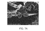
- 3A to 7B show the PTFE porous membrane A used in the example, the composite base material of Example 3, the composite base material of Example 4, and the PTFE porous membrane formed with the base layer of Example 5.
- 4 shows the results of observing the cross section near the outer surface and the cross section near the center in the thickness direction of A and the composite substrate of Example 5 with a scanning electron microscope (SEM).
- SEM scanning electron microscope
- Example 5 microscopic Raman spectroscopic measurement was performed on the cross section of the PTFE porous membrane A used, the cross section of the PTFE porous membrane A having the underlying layer formed thereon, and the cross section of the composite substrate. The results are shown in FIG. As can be seen from FIG. 8, from the cross section of the PTFE porous membrane A on which the underlayer was formed and the cross section of the composite base material, almost no peaks derived from PTFE were observed, and peaks around 1410 cm -1 and 1580 cm -1 were characteristic. peak was confirmed.
- FIG. 9 is an image mapping the peak at 731 cm ⁇ 1 for the cross section of the PTFE porous membrane A used in Example 5, based on the results of microscopic Raman spectroscopy.
- the peak at 731 cm -1 originates from the CF bond. It can be seen from FIG. 9 that the PTFE porous membrane A is untreated.
- FIG. 10 is an image mapping the peak at 1580 cm ⁇ 1 for the cross section of the PTFE porous membrane A on which the underlayer of Example 5 was formed, based on the results of microscopic Raman spectroscopy.
- FIG. 11 is an image mapping the peak at 1580 cm ⁇ 1 for the cross section of the composite substrate of Example 5, based on the results of microscopic Raman spectroscopy.
- the peak at 1580 cm ⁇ 1 originates from polymers formed from catecholamines. From FIGS. 10 and 11, it can be seen that the underlying layer is uniformly formed on the surfaces of the pores of the PTFE porous membrane A.
- Time-of-flight secondary ion mass spectrometry was performed on the cross section of the PTFE porous membrane A on which the underlayer of Example 5 was formed and the cross section of the composite substrate of Example 5. Images mapping the TOF-SIMS results are shown in FIGS. 12A-13C. As can be seen from FIGS. 12A and 12B, ion species (CN ⁇ and C 5 N ⁇ ) derived from the polymer formed from catecholamines were detected from the cross section of the PTFE porous membrane A on which the underlayer was formed. As can be seen from FIG.
- ion species (Br ⁇ ) derived from the polymerization initiation groups contained in the underlayer were also detected from the cross section of the PTFE porous membrane A on which the underlayer was formed. From FIGS. 12A to 12C, it can be confirmed that the underlayer is introduced into the inside of the PTFE porous membrane A relatively uniformly.
- ionic species CN ⁇ and C 5 N ⁇ ) derived from polymers formed from catecholamines were detected from the cross section of the composite substrate.
- ion species C 4 H 5 O 2 ⁇ ) derived from polymer chains introduced into the underlying layer were also detected from the cross section of the composite substrate. From FIGS. 13A to 13C, it can be confirmed that the underlayer and polymer chains are introduced into the PTFE porous membrane A relatively uniformly.
- the composite substrate of the present invention can be used in various applications such as sound-permeable membranes, gas-permeable membranes, separation membranes, ion-exchange membranes, diaphragms, catalysts, liquid absorbers, medical materials, etc., depending on its function.
Landscapes
- Chemical & Material Sciences (AREA)
- Organic Chemistry (AREA)
- Life Sciences & Earth Sciences (AREA)
- Engineering & Computer Science (AREA)
- Materials Engineering (AREA)
- Wood Science & Technology (AREA)
- Health & Medical Sciences (AREA)
- Chemical Kinetics & Catalysis (AREA)
- Medicinal Chemistry (AREA)
- Polymers & Plastics (AREA)
- Laminated Bodies (AREA)
Priority Applications (1)
| Application Number | Priority Date | Filing Date | Title |
|---|---|---|---|
| JP2023548397A JPWO2023042665A1 (https=) | 2021-09-15 | 2022-08-31 |
Applications Claiming Priority (2)
| Application Number | Priority Date | Filing Date | Title |
|---|---|---|---|
| JP2021150526 | 2021-09-15 | ||
| JP2021-150526 | 2021-09-15 |
Publications (1)
| Publication Number | Publication Date |
|---|---|
| WO2023042665A1 true WO2023042665A1 (ja) | 2023-03-23 |
Family
ID=85602178
Family Applications (1)
| Application Number | Title | Priority Date | Filing Date |
|---|---|---|---|
| PCT/JP2022/032887 Ceased WO2023042665A1 (ja) | 2021-09-15 | 2022-08-31 | 複合基材及びその製造方法 |
Country Status (2)
| Country | Link |
|---|---|
| JP (1) | JPWO2023042665A1 (https=) |
| WO (1) | WO2023042665A1 (https=) |
Citations (7)
| Publication number | Priority date | Publication date | Assignee | Title |
|---|---|---|---|---|
| JP2009046529A (ja) * | 2007-08-14 | 2009-03-05 | Nitto Denko Corp | 表面に親水性ポリマーを有するフッ素樹脂成形体およびその製造方法 |
| WO2014185361A1 (ja) * | 2013-05-13 | 2014-11-20 | 独立行政法人科学技術振興機構 | 新規複合材料およびそれを用いるポリマー被覆材前駆体 |
| JP2016508776A (ja) * | 2013-02-04 | 2016-03-24 | ダブリュ.エル.ゴア アンド アソシエイツ,インコーポレイティドW.L. Gore & Associates, Incorporated | 基板用コーティング |
| JP2016513545A (ja) * | 2013-03-14 | 2016-05-16 | ダブリュ.エル.ゴア アンド アソシエイツ,インコーポレイティドW.L. Gore & Associates, Incorporated | 表面のコーティング |
| US20170210872A1 (en) * | 2014-07-22 | 2017-07-27 | Universite De Strasbourg | Method for modifying the surface properties of elastomer cellular foams |
| JP2018173306A (ja) * | 2017-03-31 | 2018-11-08 | 日立化成株式会社 | 分離材及びカラム |
| WO2020202320A1 (ja) * | 2019-03-29 | 2020-10-08 | 株式会社メニコン | コンタクトレンズ消毒用過酸化水素の分解触媒およびその製造方法 |
-
2022
- 2022-08-31 WO PCT/JP2022/032887 patent/WO2023042665A1/ja not_active Ceased
- 2022-08-31 JP JP2023548397A patent/JPWO2023042665A1/ja active Pending
Patent Citations (7)
| Publication number | Priority date | Publication date | Assignee | Title |
|---|---|---|---|---|
| JP2009046529A (ja) * | 2007-08-14 | 2009-03-05 | Nitto Denko Corp | 表面に親水性ポリマーを有するフッ素樹脂成形体およびその製造方法 |
| JP2016508776A (ja) * | 2013-02-04 | 2016-03-24 | ダブリュ.エル.ゴア アンド アソシエイツ,インコーポレイティドW.L. Gore & Associates, Incorporated | 基板用コーティング |
| JP2016513545A (ja) * | 2013-03-14 | 2016-05-16 | ダブリュ.エル.ゴア アンド アソシエイツ,インコーポレイティドW.L. Gore & Associates, Incorporated | 表面のコーティング |
| WO2014185361A1 (ja) * | 2013-05-13 | 2014-11-20 | 独立行政法人科学技術振興機構 | 新規複合材料およびそれを用いるポリマー被覆材前駆体 |
| US20170210872A1 (en) * | 2014-07-22 | 2017-07-27 | Universite De Strasbourg | Method for modifying the surface properties of elastomer cellular foams |
| JP2018173306A (ja) * | 2017-03-31 | 2018-11-08 | 日立化成株式会社 | 分離材及びカラム |
| WO2020202320A1 (ja) * | 2019-03-29 | 2020-10-08 | 株式会社メニコン | コンタクトレンズ消毒用過酸化水素の分解触媒およびその製造方法 |
Also Published As
| Publication number | Publication date |
|---|---|
| JPWO2023042665A1 (https=) | 2023-03-23 |
Similar Documents
| Publication | Publication Date | Title |
|---|---|---|
| CN107683273B (zh) | 用于分离烷烃和烯烃的薄膜复合膜 | |
| CN111801359A (zh) | 含氟聚合物的制造方法 | |
| KR20030090779A (ko) | 중합체 전해질 막 | |
| CN114651018A (zh) | 含氟聚合物的制造方法、聚四氟乙烯的制造方法、全氟弹性体的制造方法和组合物 | |
| WO2015125597A1 (ja) | 硬化性組成物および高分子硬化物 | |
| TWI724171B (zh) | Dn 凝膠膜的製造方法及酸性氣體分離膜的製造方法 | |
| BR112020005935B1 (pt) | Copolímeros de olefinas halogenadas e comonômeros halogenados, método para produzir o mesmo, artigo, aglutinante de eletrodo de bateria, bateria, produto polimérico, artigo de fabricação e uso | |
| CN109642085A (zh) | 高分子材料 | |
| JP2013189595A (ja) | グラフト鎖を有する高分子電解質膜およびその製造方法 | |
| CN102149451A (zh) | 复合半透膜及其制造方法 | |
| TWI324614B (en) | Polymer grafted support polymers | |
| WO2023042665A1 (ja) | 複合基材及びその製造方法 | |
| WO2023042666A1 (ja) | 複合基材及びその製造方法 | |
| US20210197129A1 (en) | Method Of Producing A Polymeric Membrane | |
| JP7303227B2 (ja) | 孔の表面が改質された多孔質基材の製造方法及び孔の表面が改質された多孔質基材 | |
| CN106459317B (zh) | 丙烯酸系聚合物、其制造方法及含有该丙烯酸系聚合物的增塑溶胶组合物 | |
| JP2011038089A (ja) | イオン伝導体、重合性化合物、マクロ開始剤 | |
| JP2009035640A (ja) | 抗菌性フィルム | |
| JP5421688B2 (ja) | 固体酸触媒 | |
| JP5297971B2 (ja) | 揮発性有機化合物の分離膜及び揮発性有機化合物の分離除去方法 | |
| JP2007009163A (ja) | 含フッ素スチレン誘導体及びその重合体 | |
| JPWO2004078811A1 (ja) | 重合反応用溶媒および重合体製造方法 | |
| US11530283B2 (en) | Laminate | |
| KR102590260B1 (ko) | 내화학성 플루오린화 다중블록 중합체 구조체, 제조 방법 및 사용 | |
| JP6434759B2 (ja) | 気体分離膜及び気体分離膜の製造方法 |
Legal Events
| Date | Code | Title | Description |
|---|---|---|---|
| 121 | Ep: the epo has been informed by wipo that ep was designated in this application |
Ref document number: 22869812 Country of ref document: EP Kind code of ref document: A1 |
|
| WWE | Wipo information: entry into national phase |
Ref document number: 2023548397 Country of ref document: JP |
|
| NENP | Non-entry into the national phase |
Ref country code: DE |
|
| 122 | Ep: pct application non-entry in european phase |
Ref document number: 22869812 Country of ref document: EP Kind code of ref document: A1 |