WO2023042665A1 - Composite base material and manufacturing method thereof - Google Patents
Composite base material and manufacturing method thereof Download PDFInfo
- Publication number
- WO2023042665A1 WO2023042665A1 PCT/JP2022/032887 JP2022032887W WO2023042665A1 WO 2023042665 A1 WO2023042665 A1 WO 2023042665A1 JP 2022032887 W JP2022032887 W JP 2022032887W WO 2023042665 A1 WO2023042665 A1 WO 2023042665A1
- Authority
- WO
- WIPO (PCT)
- Prior art keywords
- group
- composite substrate
- pores
- catecholamines
- polymerization
- Prior art date
Links
- 239000002131 composite material Substances 0.000 title claims abstract description 121
- 239000000463 material Substances 0.000 title claims abstract description 56
- 238000004519 manufacturing process Methods 0.000 title claims description 39
- 238000006116 polymerization reaction Methods 0.000 claims abstract description 118
- 229920000642 polymer Polymers 0.000 claims abstract description 90
- 239000011148 porous material Substances 0.000 claims abstract description 88
- 230000000977 initiatory effect Effects 0.000 claims abstract description 78
- 239000011368 organic material Substances 0.000 claims abstract description 33
- 239000000758 substrate Substances 0.000 claims description 203
- 229920001343 polytetrafluoroethylene Polymers 0.000 claims description 66
- 239000004810 polytetrafluoroethylene Substances 0.000 claims description 66
- 150000003943 catecholamines Chemical class 0.000 claims description 61
- 239000000178 monomer Substances 0.000 claims description 49
- 229920005989 resin Polymers 0.000 claims description 48
- 239000011347 resin Substances 0.000 claims description 48
- 239000007788 liquid Substances 0.000 claims description 45
- XLYOFNOQVPJJNP-UHFFFAOYSA-N water Substances O XLYOFNOQVPJJNP-UHFFFAOYSA-N 0.000 claims description 44
- 125000001424 substituent group Chemical group 0.000 claims description 30
- -1 nitroxide groups Chemical group 0.000 claims description 29
- 238000000034 method Methods 0.000 claims description 23
- LFQSCWFLJHTTHZ-UHFFFAOYSA-N Ethanol Chemical compound CCO LFQSCWFLJHTTHZ-UHFFFAOYSA-N 0.000 claims description 17
- 125000004435 hydrogen atom Chemical group [H]* 0.000 claims description 15
- 238000009210 therapy by ultrasound Methods 0.000 claims description 15
- 125000005843 halogen group Chemical group 0.000 claims description 14
- 230000002209 hydrophobic effect Effects 0.000 claims description 13
- 239000004094 surface-active agent Substances 0.000 claims description 8
- 238000011049 filling Methods 0.000 claims description 7
- 230000000379 polymerizing effect Effects 0.000 claims description 6
- 125000002887 hydroxy group Chemical group [H]O* 0.000 claims description 5
- 150000001450 anions Chemical class 0.000 claims description 3
- 125000003178 carboxy group Chemical group [H]OC(*)=O 0.000 claims description 3
- 125000001183 hydrocarbyl group Chemical group 0.000 claims 1
- 239000011248 coating agent Substances 0.000 abstract 1
- 238000000576 coating method Methods 0.000 abstract 1
- OKKJLVBELUTLKV-UHFFFAOYSA-N Methanol Chemical compound OC OKKJLVBELUTLKV-UHFFFAOYSA-N 0.000 description 93
- 239000012528 membrane Substances 0.000 description 66
- 239000000243 solution Substances 0.000 description 51
- 150000002430 hydrocarbons Chemical group 0.000 description 33
- 150000001875 compounds Chemical class 0.000 description 24
- 239000012153 distilled water Substances 0.000 description 18
- 238000005011 time of flight secondary ion mass spectroscopy Methods 0.000 description 14
- 238000002042 time-of-flight secondary ion mass spectrometry Methods 0.000 description 14
- 238000013507 mapping Methods 0.000 description 13
- 239000000203 mixture Substances 0.000 description 13
- YMWUJEATGCHHMB-UHFFFAOYSA-N Dichloromethane Chemical compound ClCCl YMWUJEATGCHHMB-UHFFFAOYSA-N 0.000 description 12
- 238000006243 chemical reaction Methods 0.000 description 11
- 239000003505 polymerization initiator Substances 0.000 description 11
- 125000004432 carbon atom Chemical group C* 0.000 description 9
- VLKZOEOYAKHREP-UHFFFAOYSA-N n-Hexane Chemical compound CCCCCC VLKZOEOYAKHREP-UHFFFAOYSA-N 0.000 description 9
- 150000003254 radicals Chemical class 0.000 description 9
- 238000001878 scanning electron micrograph Methods 0.000 description 9
- 229910052723 transition metal Inorganic materials 0.000 description 9
- 150000003624 transition metals Chemical class 0.000 description 9
- 238000001069 Raman spectroscopy Methods 0.000 description 8
- 230000000052 comparative effect Effects 0.000 description 8
- 239000002904 solvent Substances 0.000 description 8
- QKNYBSVHEMOAJP-UHFFFAOYSA-N 2-amino-2-(hydroxymethyl)propane-1,3-diol;hydron;chloride Chemical compound Cl.OCC(N)(CO)CO QKNYBSVHEMOAJP-UHFFFAOYSA-N 0.000 description 7
- XEKOWRVHYACXOJ-UHFFFAOYSA-N Ethyl acetate Chemical compound CCOC(C)=O XEKOWRVHYACXOJ-UHFFFAOYSA-N 0.000 description 6
- 239000002202 Polyethylene glycol Substances 0.000 description 6
- WYURNTSHIVDZCO-UHFFFAOYSA-N Tetrahydrofuran Chemical compound C1CCOC1 WYURNTSHIVDZCO-UHFFFAOYSA-N 0.000 description 6
- RAXXELZNTBOGNW-UHFFFAOYSA-N imidazole Natural products C1=CNC=N1 RAXXELZNTBOGNW-UHFFFAOYSA-N 0.000 description 6
- 239000003446 ligand Substances 0.000 description 6
- 229920001223 polyethylene glycol Polymers 0.000 description 6
- 238000010526 radical polymerization reaction Methods 0.000 description 6
- CERQOIWHTDAKMF-UHFFFAOYSA-N Methacrylic acid Chemical compound CC(=C)C(O)=O CERQOIWHTDAKMF-UHFFFAOYSA-N 0.000 description 5
- ZMXDDKWLCZADIW-UHFFFAOYSA-N N,N-Dimethylformamide Chemical compound CN(C)C=O ZMXDDKWLCZADIW-UHFFFAOYSA-N 0.000 description 5
- 238000010560 atom transfer radical polymerization reaction Methods 0.000 description 5
- 125000001246 bromo group Chemical group Br* 0.000 description 5
- 239000000872 buffer Substances 0.000 description 5
- 229910052731 fluorine Inorganic materials 0.000 description 5
- 125000003827 glycol group Chemical group 0.000 description 5
- 125000002496 methyl group Chemical group [H]C([H])([H])* 0.000 description 5
- 239000000126 substance Substances 0.000 description 5
- NAWXUBYGYWOOIX-SFHVURJKSA-N (2s)-2-[[4-[2-(2,4-diaminoquinazolin-6-yl)ethyl]benzoyl]amino]-4-methylidenepentanedioic acid Chemical compound C1=CC2=NC(N)=NC(N)=C2C=C1CCC1=CC=C(C(=O)N[C@@H](CC(=C)C(O)=O)C(O)=O)C=C1 NAWXUBYGYWOOIX-SFHVURJKSA-N 0.000 description 4
- YOCIJWAHRAJQFT-UHFFFAOYSA-N 2-bromo-2-methylpropanoyl bromide Chemical compound CC(C)(Br)C(Br)=O YOCIJWAHRAJQFT-UHFFFAOYSA-N 0.000 description 4
- CSCPPACGZOOCGX-UHFFFAOYSA-N Acetone Chemical compound CC(C)=O CSCPPACGZOOCGX-UHFFFAOYSA-N 0.000 description 4
- HRPVXLWXLXDGHG-UHFFFAOYSA-N Acrylamide Chemical compound NC(=O)C=C HRPVXLWXLXDGHG-UHFFFAOYSA-N 0.000 description 4
- YCKRFDGAMUMZLT-UHFFFAOYSA-N Fluorine atom Chemical compound [F] YCKRFDGAMUMZLT-UHFFFAOYSA-N 0.000 description 4
- 238000004833 X-ray photoelectron spectroscopy Methods 0.000 description 4
- 125000002252 acyl group Chemical group 0.000 description 4
- 150000001336 alkenes Chemical class 0.000 description 4
- 239000012298 atmosphere Substances 0.000 description 4
- 238000009826 distribution Methods 0.000 description 4
- 125000001495 ethyl group Chemical group [H]C([H])([H])C([H])([H])* 0.000 description 4
- 125000000816 ethylene group Chemical group [H]C([H])([*:1])C([H])([H])[*:2] 0.000 description 4
- 239000011737 fluorine Substances 0.000 description 4
- 238000010438 heat treatment Methods 0.000 description 4
- IJGRMHOSHXDMSA-UHFFFAOYSA-N Atomic nitrogen Chemical compound N#N IJGRMHOSHXDMSA-UHFFFAOYSA-N 0.000 description 3
- VEXZGXHMUGYJMC-UHFFFAOYSA-M Chloride anion Chemical compound [Cl-] VEXZGXHMUGYJMC-UHFFFAOYSA-M 0.000 description 3
- XEEYBQQBJWHFJM-UHFFFAOYSA-N Iron Chemical compound [Fe] XEEYBQQBJWHFJM-UHFFFAOYSA-N 0.000 description 3
- 239000004372 Polyvinyl alcohol Substances 0.000 description 3
- ZMANZCXQSJIPKH-UHFFFAOYSA-N Triethylamine Chemical compound CCN(CC)CC ZMANZCXQSJIPKH-UHFFFAOYSA-N 0.000 description 3
- 150000001298 alcohols Chemical class 0.000 description 3
- 230000005540 biological transmission Effects 0.000 description 3
- 230000015572 biosynthetic process Effects 0.000 description 3
- DCFKHNIGBAHNSS-UHFFFAOYSA-N chloro(triethyl)silane Chemical compound CC[Si](Cl)(CC)CC DCFKHNIGBAHNSS-UHFFFAOYSA-N 0.000 description 3
- 238000007796 conventional method Methods 0.000 description 3
- 229910001873 dinitrogen Inorganic materials 0.000 description 3
- VYFYYTLLBUKUHU-UHFFFAOYSA-N dopamine Chemical class NCCC1=CC=C(O)C(O)=C1 VYFYYTLLBUKUHU-UHFFFAOYSA-N 0.000 description 3
- 238000001035 drying Methods 0.000 description 3
- 150000002475 indoles Chemical class 0.000 description 3
- 229910010272 inorganic material Inorganic materials 0.000 description 3
- 239000011147 inorganic material Substances 0.000 description 3
- 150000002500 ions Chemical class 0.000 description 3
- 238000012705 nitroxide-mediated radical polymerization Methods 0.000 description 3
- 150000002871 norepinephrines Chemical class 0.000 description 3
- UKODFQOELJFMII-UHFFFAOYSA-N pentamethyldiethylenetriamine Chemical compound CN(C)CCN(C)CCN(C)C UKODFQOELJFMII-UHFFFAOYSA-N 0.000 description 3
- 239000012466 permeate Substances 0.000 description 3
- 229920001690 polydopamine Polymers 0.000 description 3
- 229920002451 polyvinyl alcohol Polymers 0.000 description 3
- 238000000550 scanning electron microscopy energy dispersive X-ray spectroscopy Methods 0.000 description 3
- YLQBMQCUIZJEEH-UHFFFAOYSA-N tetrahydrofuran Natural products C=1C=COC=1 YLQBMQCUIZJEEH-UHFFFAOYSA-N 0.000 description 3
- 229920001567 vinyl ester resin Chemical class 0.000 description 3
- 125000000391 vinyl group Chemical class [H]C([*])=C([H])[H] 0.000 description 3
- YBYIRNPNPLQARY-UHFFFAOYSA-N 1H-indene Chemical compound C1=CC=C2CC=CC2=C1 YBYIRNPNPLQARY-UHFFFAOYSA-N 0.000 description 2
- NIXOWILDQLNWCW-UHFFFAOYSA-N 2-Propenoic acid Natural products OC(=O)C=C NIXOWILDQLNWCW-UHFFFAOYSA-N 0.000 description 2
- MKYLYILBGJSJRA-UHFFFAOYSA-N 2-bromo-N-hexyl-2-methylpropanamide Chemical compound CCCCCCNC(=O)C(C)(C)Br MKYLYILBGJSJRA-UHFFFAOYSA-N 0.000 description 2
- RYGMFSIKBFXOCR-UHFFFAOYSA-N Copper Chemical compound [Cu] RYGMFSIKBFXOCR-UHFFFAOYSA-N 0.000 description 2
- CTENFNNZBMHDDG-UHFFFAOYSA-N Dopamine hydrochloride Chemical compound Cl.NCCC1=CC=C(O)C(O)=C1 CTENFNNZBMHDDG-UHFFFAOYSA-N 0.000 description 2
- 229920000219 Ethylene vinyl alcohol Polymers 0.000 description 2
- RRHGJUQNOFWUDK-UHFFFAOYSA-N Isoprene Chemical compound CC(=C)C=C RRHGJUQNOFWUDK-UHFFFAOYSA-N 0.000 description 2
- KFZMGEQAYNKOFK-UHFFFAOYSA-N Isopropanol Chemical compound CC(C)O KFZMGEQAYNKOFK-UHFFFAOYSA-N 0.000 description 2
- BAPJBEWLBFYGME-UHFFFAOYSA-N Methyl acrylate Chemical compound COC(=O)C=C BAPJBEWLBFYGME-UHFFFAOYSA-N 0.000 description 2
- PXHVJJICTQNCMI-UHFFFAOYSA-N Nickel Chemical compound [Ni] PXHVJJICTQNCMI-UHFFFAOYSA-N 0.000 description 2
- 239000002033 PVDF binder Substances 0.000 description 2
- KDLHZDBZIXYQEI-UHFFFAOYSA-N Palladium Chemical compound [Pd] KDLHZDBZIXYQEI-UHFFFAOYSA-N 0.000 description 2
- 239000004813 Perfluoroalkoxy alkane Substances 0.000 description 2
- 239000004698 Polyethylene Substances 0.000 description 2
- 239000004743 Polypropylene Substances 0.000 description 2
- PPBRXRYQALVLMV-UHFFFAOYSA-N Styrene Chemical compound C=CC1=CC=CC=C1 PPBRXRYQALVLMV-UHFFFAOYSA-N 0.000 description 2
- 125000002947 alkylene group Chemical group 0.000 description 2
- 125000003277 amino group Chemical group 0.000 description 2
- RDOXTESZEPMUJZ-UHFFFAOYSA-N anisole Chemical compound COC1=CC=CC=C1 RDOXTESZEPMUJZ-UHFFFAOYSA-N 0.000 description 2
- 239000007864 aqueous solution Substances 0.000 description 2
- 229910052794 bromium Inorganic materials 0.000 description 2
- 239000003054 catalyst Substances 0.000 description 2
- 239000012295 chemical reaction liquid Substances 0.000 description 2
- 239000007795 chemical reaction product Substances 0.000 description 2
- 229910052801 chlorine Inorganic materials 0.000 description 2
- 239000000460 chlorine Substances 0.000 description 2
- 229910052802 copper Inorganic materials 0.000 description 2
- 239000010949 copper Substances 0.000 description 2
- 229960001149 dopamine hydrochloride Drugs 0.000 description 2
- 125000000524 functional group Chemical group 0.000 description 2
- 239000012535 impurity Substances 0.000 description 2
- 125000001041 indolyl group Chemical group 0.000 description 2
- 230000001678 irradiating effect Effects 0.000 description 2
- 125000001449 isopropyl group Chemical group [H]C([H])([H])C([H])(*)C([H])([H])[H] 0.000 description 2
- 238000005259 measurement Methods 0.000 description 2
- 229910052751 metal Inorganic materials 0.000 description 2
- 239000002184 metal Substances 0.000 description 2
- 125000001570 methylene group Chemical group [H]C([H])([*:1])[*:2] 0.000 description 2
- 238000002156 mixing Methods 0.000 description 2
- 150000002825 nitriles Chemical class 0.000 description 2
- 239000004745 nonwoven fabric Substances 0.000 description 2
- 239000012074 organic phase Substances 0.000 description 2
- 125000004430 oxygen atom Chemical group O* 0.000 description 2
- 229920011301 perfluoro alkoxyl alkane Polymers 0.000 description 2
- 125000005010 perfluoroalkyl group Chemical group 0.000 description 2
- 229920001155 polypropylene Polymers 0.000 description 2
- 229920002981 polyvinylidene fluoride Polymers 0.000 description 2
- 125000001436 propyl group Chemical group [H]C([*])([H])C([H])([H])C([H])([H])[H] 0.000 description 2
- 238000001226 reprecipitation Methods 0.000 description 2
- 238000010898 silica gel chromatography Methods 0.000 description 2
- 238000003756 stirring Methods 0.000 description 2
- 150000003440 styrenes Chemical class 0.000 description 2
- 238000003786 synthesis reaction Methods 0.000 description 2
- 125000003258 trimethylene group Chemical group [H]C([H])([*:2])C([H])([H])C([H])([H])[*:1] 0.000 description 2
- RIOQSEWOXXDEQQ-UHFFFAOYSA-N triphenylphosphine Chemical compound C1=CC=CC=C1P(C=1C=CC=CC=1)C1=CC=CC=C1 RIOQSEWOXXDEQQ-UHFFFAOYSA-N 0.000 description 2
- LENZDBCJOHFCAS-UHFFFAOYSA-N tris Chemical compound OCC(N)(CO)CO LENZDBCJOHFCAS-UHFFFAOYSA-N 0.000 description 2
- 229920002554 vinyl polymer Polymers 0.000 description 2
- 238000005303 weighing Methods 0.000 description 2
- 239000002759 woven fabric Substances 0.000 description 2
- SLRCCWJSBJZJBV-LXTVHRRPSA-N (-)-Spartein Natural products C1N2CCCC[C@@H]2[C@H]2CN3CCCC[C@@H]3[C@H]1C2 SLRCCWJSBJZJBV-LXTVHRRPSA-N 0.000 description 1
- YKFCISHFRZHKHY-NGQGLHOPSA-N (2s)-2-amino-3-(3,4-dihydroxyphenyl)-2-methylpropanoic acid;trihydrate Chemical compound O.O.O.OC(=O)[C@](N)(C)CC1=CC=C(O)C(O)=C1.OC(=O)[C@](N)(C)CC1=CC=C(O)C(O)=C1 YKFCISHFRZHKHY-NGQGLHOPSA-N 0.000 description 1
- QXWYKJLNLSIPIN-YUMQZZPRSA-N (2s,3s)-2-azaniumyl-3-(3,4-dihydroxyphenyl)-3-hydroxypropanoate Chemical compound [O-]C(=O)[C@@H]([NH3+])[C@@H](O)C1=CC=C(O)C(O)=C1 QXWYKJLNLSIPIN-YUMQZZPRSA-N 0.000 description 1
- UCTWMZQNUQWSLP-VIFPVBQESA-N (R)-adrenaline Chemical compound CNC[C@H](O)C1=CC=C(O)C(O)=C1 UCTWMZQNUQWSLP-VIFPVBQESA-N 0.000 description 1
- 229930182837 (R)-adrenaline Natural products 0.000 description 1
- BYEAHWXPCBROCE-UHFFFAOYSA-N 1,1,1,3,3,3-hexafluoropropan-2-ol Chemical compound FC(F)(F)C(O)C(F)(F)F BYEAHWXPCBROCE-UHFFFAOYSA-N 0.000 description 1
- XQBHAZDVLGNSOJ-UHFFFAOYSA-N 1-(4-ethenylphenyl)-n,n-dimethylmethanamine Chemical compound CN(C)CC1=CC=C(C=C)C=C1 XQBHAZDVLGNSOJ-UHFFFAOYSA-N 0.000 description 1
- VXNZUUAINFGPBY-UHFFFAOYSA-N 1-Butene Chemical compound CCC=C VXNZUUAINFGPBY-UHFFFAOYSA-N 0.000 description 1
- SLBOQBILGNEPEB-UHFFFAOYSA-N 1-chloroprop-2-enylbenzene Chemical compound C=CC(Cl)C1=CC=CC=C1 SLBOQBILGNEPEB-UHFFFAOYSA-N 0.000 description 1
- SMZOUWXMTYCWNB-UHFFFAOYSA-N 2-(2-methoxy-5-methylphenyl)ethanamine Chemical compound COC1=CC=C(C)C=C1CCN SMZOUWXMTYCWNB-UHFFFAOYSA-N 0.000 description 1
- OEPOKWHJYJXUGD-UHFFFAOYSA-N 2-(3-phenylmethoxyphenyl)-1,3-thiazole-4-carbaldehyde Chemical compound O=CC1=CSC(C=2C=C(OCC=3C=CC=CC=3)C=CC=2)=N1 OEPOKWHJYJXUGD-UHFFFAOYSA-N 0.000 description 1
- HXLLCROMVONRRO-UHFFFAOYSA-N 2-butoxyethenylbenzene Chemical compound CCCCOC=CC1=CC=CC=C1 HXLLCROMVONRRO-UHFFFAOYSA-N 0.000 description 1
- XUDBVJCTLZTSDC-UHFFFAOYSA-N 2-ethenylbenzoic acid Chemical compound OC(=O)C1=CC=CC=C1C=C XUDBVJCTLZTSDC-UHFFFAOYSA-N 0.000 description 1
- 125000000954 2-hydroxyethyl group Chemical group [H]C([*])([H])C([H])([H])O[H] 0.000 description 1
- QENRKQYUEGJNNZ-UHFFFAOYSA-N 2-methyl-1-(prop-2-enoylamino)propane-1-sulfonic acid Chemical compound CC(C)C(S(O)(=O)=O)NC(=O)C=C QENRKQYUEGJNNZ-UHFFFAOYSA-N 0.000 description 1
- KGIGUEBEKRSTEW-UHFFFAOYSA-N 2-vinylpyridine Chemical compound C=CC1=CC=CC=N1 KGIGUEBEKRSTEW-UHFFFAOYSA-N 0.000 description 1
- FQTFHMSZCSUVEU-UHFFFAOYSA-N 4-(2-amino-1-hydroxyethyl)benzene-1,2-diol;hydron;chloride Chemical compound Cl.NCC(O)C1=CC=C(O)C(O)=C1 FQTFHMSZCSUVEU-UHFFFAOYSA-N 0.000 description 1
- FQTFHMSZCSUVEU-QRPNPIFTSA-N 4-[(1r)-2-amino-1-hydroxyethyl]benzene-1,2-diol;hydrochloride Chemical compound Cl.NC[C@H](O)C1=CC=C(O)C(O)=C1 FQTFHMSZCSUVEU-QRPNPIFTSA-N 0.000 description 1
- KOYDOSLEMQLNJW-UHFFFAOYSA-N 4-heptyl-2-(4-heptylpyridin-2-yl)pyridine Chemical compound CCCCCCCC1=CC=NC(C=2N=CC=C(CCCCCCC)C=2)=C1 KOYDOSLEMQLNJW-UHFFFAOYSA-N 0.000 description 1
- 239000004925 Acrylic resin Substances 0.000 description 1
- 229920000178 Acrylic resin Polymers 0.000 description 1
- NLHHRLWOUZZQLW-UHFFFAOYSA-N Acrylonitrile Chemical compound C=CC#N NLHHRLWOUZZQLW-UHFFFAOYSA-N 0.000 description 1
- ROFVEXUMMXZLPA-UHFFFAOYSA-N Bipyridyl Chemical compound N1=CC=CC=C1C1=CC=CC=N1 ROFVEXUMMXZLPA-UHFFFAOYSA-N 0.000 description 1
- CPELXLSAUQHCOX-UHFFFAOYSA-M Bromide Chemical compound [Br-] CPELXLSAUQHCOX-UHFFFAOYSA-M 0.000 description 1
- WKBOTKDWSSQWDR-UHFFFAOYSA-N Bromine atom Chemical compound [Br] WKBOTKDWSSQWDR-UHFFFAOYSA-N 0.000 description 1
- ZAMOUSCENKQFHK-UHFFFAOYSA-N Chlorine atom Chemical compound [Cl] ZAMOUSCENKQFHK-UHFFFAOYSA-N 0.000 description 1
- 229910021591 Copper(I) chloride Inorganic materials 0.000 description 1
- VEXZGXHMUGYJMC-UHFFFAOYSA-N Hydrochloric acid Chemical compound Cl VEXZGXHMUGYJMC-UHFFFAOYSA-N 0.000 description 1
- WOBHKFSMXKNTIM-UHFFFAOYSA-N Hydroxyethyl methacrylate Chemical compound CC(=C)C(=O)OCCO WOBHKFSMXKNTIM-UHFFFAOYSA-N 0.000 description 1
- WTDRDQBEARUVNC-LURJTMIESA-N L-DOPA Chemical compound OC(=O)[C@@H](N)CC1=CC=C(O)C(O)=C1 WTDRDQBEARUVNC-LURJTMIESA-N 0.000 description 1
- WTDRDQBEARUVNC-UHFFFAOYSA-N L-Dopa Natural products OC(=O)C(N)CC1=CC=C(O)C(O)=C1 WTDRDQBEARUVNC-UHFFFAOYSA-N 0.000 description 1
- 239000004696 Poly ether ether ketone Substances 0.000 description 1
- 239000004695 Polyether sulfone Substances 0.000 description 1
- 239000004697 Polyetherimide Substances 0.000 description 1
- KJTLSVCANCCWHF-UHFFFAOYSA-N Ruthenium Chemical compound [Ru] KJTLSVCANCCWHF-UHFFFAOYSA-N 0.000 description 1
- FAPWRFPIFSIZLT-UHFFFAOYSA-M Sodium chloride Chemical class [Na+].[Cl-] FAPWRFPIFSIZLT-UHFFFAOYSA-M 0.000 description 1
- FEWJPZIEWOKRBE-UHFFFAOYSA-N Tartaric acid Natural products [H+].[H+].[O-]C(=O)C(O)C(O)C([O-])=O FEWJPZIEWOKRBE-UHFFFAOYSA-N 0.000 description 1
- 239000007983 Tris buffer Substances 0.000 description 1
- XTXRWKRVRITETP-UHFFFAOYSA-N Vinyl acetate Chemical compound CC(=O)OC=C XTXRWKRVRITETP-UHFFFAOYSA-N 0.000 description 1
- BZHJMEDXRYGGRV-UHFFFAOYSA-N Vinyl chloride Chemical compound ClC=C BZHJMEDXRYGGRV-UHFFFAOYSA-N 0.000 description 1
- DGEZNRSVGBDHLK-UHFFFAOYSA-N [1,10]phenanthroline Chemical compound C1=CN=C2C3=NC=CC=C3C=CC2=C1 DGEZNRSVGBDHLK-UHFFFAOYSA-N 0.000 description 1
- 239000006096 absorbing agent Substances 0.000 description 1
- 239000002253 acid Substances 0.000 description 1
- 150000007513 acids Chemical class 0.000 description 1
- 150000003926 acrylamides Chemical class 0.000 description 1
- 125000000777 acyl halide group Chemical group 0.000 description 1
- 125000003545 alkoxy group Chemical group 0.000 description 1
- 239000000956 alloy Substances 0.000 description 1
- XYLMUPLGERFSHI-UHFFFAOYSA-N alpha-Methylstyrene Chemical compound CC(=C)C1=CC=CC=C1 XYLMUPLGERFSHI-UHFFFAOYSA-N 0.000 description 1
- SLRCCWJSBJZJBV-UHFFFAOYSA-N alpha-isosparteine Natural products C1N2CCCCC2C2CN3CCCCC3C1C2 SLRCCWJSBJZJBV-UHFFFAOYSA-N 0.000 description 1
- XFOZBWSTIQRFQW-UHFFFAOYSA-M benzyl-dimethyl-prop-2-enylazanium;chloride Chemical compound [Cl-].C=CC[N+](C)(C)CC1=CC=CC=C1 XFOZBWSTIQRFQW-UHFFFAOYSA-M 0.000 description 1
- GDTBXPJZTBHREO-UHFFFAOYSA-N bromine Substances BrBr GDTBXPJZTBHREO-UHFFFAOYSA-N 0.000 description 1
- 230000005587 bubbling Effects 0.000 description 1
- 239000007853 buffer solution Substances 0.000 description 1
- IAQRGUVFOMOMEM-UHFFFAOYSA-N butene Natural products CC=CC IAQRGUVFOMOMEM-UHFFFAOYSA-N 0.000 description 1
- 125000000484 butyl group Chemical group [H]C([*])([H])C([H])([H])C([H])([H])C([H])([H])[H] 0.000 description 1
- YCIMNLLNPGFGHC-UHFFFAOYSA-N catechol Chemical group OC1=CC=CC=C1O YCIMNLLNPGFGHC-UHFFFAOYSA-N 0.000 description 1
- 229940083181 centrally acting adntiadrenergic agent methyldopa Drugs 0.000 description 1
- 238000004140 cleaning Methods 0.000 description 1
- OXBLHERUFWYNTN-UHFFFAOYSA-M copper(I) chloride Chemical compound [Cu]Cl OXBLHERUFWYNTN-UHFFFAOYSA-M 0.000 description 1
- 238000007872 degassing Methods 0.000 description 1
- 230000006866 deterioration Effects 0.000 description 1
- 125000002147 dimethylamino group Chemical group [H]C([H])([H])N(*)C([H])([H])[H] 0.000 description 1
- 229960001104 droxidopa Drugs 0.000 description 1
- 229920001971 elastomer Polymers 0.000 description 1
- 238000010894 electron beam technology Methods 0.000 description 1
- 238000002149 energy-dispersive X-ray emission spectroscopy Methods 0.000 description 1
- 230000007613 environmental effect Effects 0.000 description 1
- 229960005139 epinephrine Drugs 0.000 description 1
- UIWXSTHGICQLQT-UHFFFAOYSA-N ethenyl propanoate Chemical compound CCC(=O)OC=C UIWXSTHGICQLQT-UHFFFAOYSA-N 0.000 description 1
- 150000002170 ethers Chemical class 0.000 description 1
- 239000004715 ethylene vinyl alcohol Substances 0.000 description 1
- 238000000605 extraction Methods 0.000 description 1
- 239000000835 fiber Substances 0.000 description 1
- 239000000706 filtrate Substances 0.000 description 1
- RMBPEFMHABBEKP-UHFFFAOYSA-N fluorene Chemical compound C1=CC=C2C3=C[CH]C=CC3=CC2=C1 RMBPEFMHABBEKP-UHFFFAOYSA-N 0.000 description 1
- 150000002222 fluorine compounds Chemical class 0.000 description 1
- 230000008014 freezing Effects 0.000 description 1
- 238000007710 freezing Methods 0.000 description 1
- 239000011521 glass Substances 0.000 description 1
- 125000005842 heteroatom Chemical group 0.000 description 1
- 125000004051 hexyl group Chemical group [H]C([H])([H])C([H])([H])C([H])([H])C([H])([H])C([H])([H])C([H])([H])* 0.000 description 1
- 239000011261 inert gas Substances 0.000 description 1
- 239000004615 ingredient Substances 0.000 description 1
- PNDPGZBMCMUPRI-UHFFFAOYSA-N iodine Chemical compound II PNDPGZBMCMUPRI-UHFFFAOYSA-N 0.000 description 1
- 229910052740 iodine Inorganic materials 0.000 description 1
- 239000003014 ion exchange membrane Substances 0.000 description 1
- 229910052742 iron Inorganic materials 0.000 description 1
- 150000002576 ketones Chemical class 0.000 description 1
- 229960004502 levodopa Drugs 0.000 description 1
- 239000012567 medical material Substances 0.000 description 1
- 229910001092 metal group alloy Inorganic materials 0.000 description 1
- 229910044991 metal oxide Inorganic materials 0.000 description 1
- 150000004706 metal oxides Chemical class 0.000 description 1
- 150000002739 metals Chemical class 0.000 description 1
- UZKWTJUDCOPSNM-UHFFFAOYSA-N methoxybenzene Substances CCCCOC=C UZKWTJUDCOPSNM-UHFFFAOYSA-N 0.000 description 1
- 239000012046 mixed solvent Substances 0.000 description 1
- 238000012986 modification Methods 0.000 description 1
- 230000004048 modification Effects 0.000 description 1
- VMGSQCIDWAUGLQ-UHFFFAOYSA-N n',n'-bis[2-(dimethylamino)ethyl]-n,n-dimethylethane-1,2-diamine Chemical compound CN(C)CCN(CCN(C)C)CCN(C)C VMGSQCIDWAUGLQ-UHFFFAOYSA-N 0.000 description 1
- DWFKOMDBEKIATP-UHFFFAOYSA-N n'-[2-[2-(dimethylamino)ethyl-methylamino]ethyl]-n,n,n'-trimethylethane-1,2-diamine Chemical compound CN(C)CCN(C)CCN(C)CCN(C)C DWFKOMDBEKIATP-UHFFFAOYSA-N 0.000 description 1
- PZUGJLOCXUNFLM-UHFFFAOYSA-N n-ethenylaniline Chemical compound C=CNC1=CC=CC=C1 PZUGJLOCXUNFLM-UHFFFAOYSA-N 0.000 description 1
- 229910052759 nickel Inorganic materials 0.000 description 1
- 229910052757 nitrogen Inorganic materials 0.000 description 1
- 239000012299 nitrogen atmosphere Substances 0.000 description 1
- 125000004433 nitrogen atom Chemical group N* 0.000 description 1
- NIHNNTQXNPWCJQ-UHFFFAOYSA-N o-biphenylenemethane Natural products C1=CC=C2CC3=CC=CC=C3C2=C1 NIHNNTQXNPWCJQ-UHFFFAOYSA-N 0.000 description 1
- 125000002347 octyl group Chemical group [H]C([*])([H])C([H])([H])C([H])([H])C([H])([H])C([H])([H])C([H])([H])C([H])([H])C([H])([H])[H] 0.000 description 1
- 239000003921 oil Substances 0.000 description 1
- 239000003960 organic solvent Substances 0.000 description 1
- 229910052763 palladium Inorganic materials 0.000 description 1
- 230000000149 penetrating effect Effects 0.000 description 1
- 230000035515 penetration Effects 0.000 description 1
- 230000000737 periodic effect Effects 0.000 description 1
- 229920005668 polycarbonate resin Polymers 0.000 description 1
- 239000004431 polycarbonate resin Substances 0.000 description 1
- 229920006393 polyether sulfone Polymers 0.000 description 1
- 229920002530 polyetherether ketone Polymers 0.000 description 1
- 229920001601 polyetherimide Polymers 0.000 description 1
- 229920000573 polyethylene Polymers 0.000 description 1
- 229920000139 polyethylene terephthalate Polymers 0.000 description 1
- 239000005020 polyethylene terephthalate Substances 0.000 description 1
- 229920001721 polyimide Polymers 0.000 description 1
- 239000009719 polyimide resin Substances 0.000 description 1
- 229920006254 polymer film Polymers 0.000 description 1
- 229920005672 polyolefin resin Polymers 0.000 description 1
- 229920005990 polystyrene resin Polymers 0.000 description 1
- 239000000047 product Substances 0.000 description 1
- 125000001453 quaternary ammonium group Chemical group 0.000 description 1
- 229910052702 rhenium Inorganic materials 0.000 description 1
- WUAPFZMCVAUBPE-UHFFFAOYSA-N rhenium atom Chemical compound [Re] WUAPFZMCVAUBPE-UHFFFAOYSA-N 0.000 description 1
- 229910052703 rhodium Inorganic materials 0.000 description 1
- 239000010948 rhodium Substances 0.000 description 1
- MHOVAHRLVXNVSD-UHFFFAOYSA-N rhodium atom Chemical compound [Rh] MHOVAHRLVXNVSD-UHFFFAOYSA-N 0.000 description 1
- 229910052707 ruthenium Inorganic materials 0.000 description 1
- 150000003839 salts Chemical class 0.000 description 1
- 238000000926 separation method Methods 0.000 description 1
- 239000010703 silicon Substances 0.000 description 1
- 229910052710 silicon Inorganic materials 0.000 description 1
- MNCGMVDMOKPCSQ-UHFFFAOYSA-M sodium;2-phenylethenesulfonate Chemical compound [Na+].[O-]S(=O)(=O)C=CC1=CC=CC=C1 MNCGMVDMOKPCSQ-UHFFFAOYSA-M 0.000 description 1
- 239000007787 solid Substances 0.000 description 1
- 238000000527 sonication Methods 0.000 description 1
- 238000001179 sorption measurement Methods 0.000 description 1
- SLRCCWJSBJZJBV-AJNGGQMLSA-N sparteine Chemical compound C1N2CCCC[C@H]2[C@@H]2CN3CCCC[C@H]3[C@H]1C2 SLRCCWJSBJZJBV-AJNGGQMLSA-N 0.000 description 1
- 229960001945 sparteine Drugs 0.000 description 1
- 230000008961 swelling Effects 0.000 description 1
- 235000002906 tartaric acid Nutrition 0.000 description 1
- 239000011975 tartaric acid Substances 0.000 description 1
- 125000000999 tert-butyl group Chemical group [H]C([H])([H])C(*)(C([H])([H])[H])C([H])([H])[H] 0.000 description 1
- 238000012360 testing method Methods 0.000 description 1
- BFKJFAAPBSQJPD-UHFFFAOYSA-N tetrafluoroethene Chemical group FC(F)=C(F)F BFKJFAAPBSQJPD-UHFFFAOYSA-N 0.000 description 1
- TUQOTMZNTHZOKS-UHFFFAOYSA-N tributylphosphine Chemical compound CCCCP(CCCC)CCCC TUQOTMZNTHZOKS-UHFFFAOYSA-N 0.000 description 1
- 238000005406 washing Methods 0.000 description 1
Images


Classifications
-
- B—PERFORMING OPERATIONS; TRANSPORTING
- B32—LAYERED PRODUCTS
- B32B—LAYERED PRODUCTS, i.e. PRODUCTS BUILT-UP OF STRATA OF FLAT OR NON-FLAT, e.g. CELLULAR OR HONEYCOMB, FORM
- B32B27/00—Layered products comprising a layer of synthetic resin
- B32B27/30—Layered products comprising a layer of synthetic resin comprising vinyl (co)polymers; comprising acrylic (co)polymers
-
- B—PERFORMING OPERATIONS; TRANSPORTING
- B32—LAYERED PRODUCTS
- B32B—LAYERED PRODUCTS, i.e. PRODUCTS BUILT-UP OF STRATA OF FLAT OR NON-FLAT, e.g. CELLULAR OR HONEYCOMB, FORM
- B32B5/00—Layered products characterised by the non- homogeneity or physical structure, i.e. comprising a fibrous, filamentary, particulate or foam layer; Layered products characterised by having a layer differing constitutionally or physically in different parts
- B32B5/18—Layered products characterised by the non- homogeneity or physical structure, i.e. comprising a fibrous, filamentary, particulate or foam layer; Layered products characterised by having a layer differing constitutionally or physically in different parts characterised by features of a layer of foamed material
-
- C—CHEMISTRY; METALLURGY
- C08—ORGANIC MACROMOLECULAR COMPOUNDS; THEIR PREPARATION OR CHEMICAL WORKING-UP; COMPOSITIONS BASED THEREON
- C08G—MACROMOLECULAR COMPOUNDS OBTAINED OTHERWISE THAN BY REACTIONS ONLY INVOLVING UNSATURATED CARBON-TO-CARBON BONDS
- C08G61/00—Macromolecular compounds obtained by reactions forming a carbon-to-carbon link in the main chain of the macromolecule
-
- C—CHEMISTRY; METALLURGY
- C09—DYES; PAINTS; POLISHES; NATURAL RESINS; ADHESIVES; COMPOSITIONS NOT OTHERWISE PROVIDED FOR; APPLICATIONS OF MATERIALS NOT OTHERWISE PROVIDED FOR
- C09D—COATING COMPOSITIONS, e.g. PAINTS, VARNISHES OR LACQUERS; FILLING PASTES; CHEMICAL PAINT OR INK REMOVERS; INKS; CORRECTING FLUIDS; WOODSTAINS; PASTES OR SOLIDS FOR COLOURING OR PRINTING; USE OF MATERIALS THEREFOR
- C09D201/00—Coating compositions based on unspecified macromolecular compounds
- C09D201/02—Coating compositions based on unspecified macromolecular compounds characterised by the presence of specified groups, e.g. terminal or pendant functional groups
-
- C—CHEMISTRY; METALLURGY
- C09—DYES; PAINTS; POLISHES; NATURAL RESINS; ADHESIVES; COMPOSITIONS NOT OTHERWISE PROVIDED FOR; APPLICATIONS OF MATERIALS NOT OTHERWISE PROVIDED FOR
- C09D—COATING COMPOSITIONS, e.g. PAINTS, VARNISHES OR LACQUERS; FILLING PASTES; CHEMICAL PAINT OR INK REMOVERS; INKS; CORRECTING FLUIDS; WOODSTAINS; PASTES OR SOLIDS FOR COLOURING OR PRINTING; USE OF MATERIALS THEREFOR
- C09D5/00—Coating compositions, e.g. paints, varnishes or lacquers, characterised by their physical nature or the effects produced; Filling pastes
Definitions
- the present invention relates to a composite base material and a manufacturing method thereof.
- Polymer chains can be introduced, for example, by generating radicals on the surface of the base material and polymerizing the monomer group with the radicals. Radicals can be generated, for example, by irradiating the surface of the substrate with energy rays such as ultraviolet rays, electron rays, gamma rays, or plasma.
- Patent Document 1 discloses a method of introducing polymer chains onto the surface of a substrate without using energy rays or plasma. Specifically, Patent Document 1 discloses that a base layer to which a polymerization initiator is fixed is formed on the surface of a base material, and a polymer film is produced by polymerizing a monomer starting from the polymerization initiator. disclosed. In Patent Document 1, the underlying layer is composed of polydopamine, which is an organic material. According to the method of Patent Literature 1, polymer chains can be easily introduced to the surface of the base material regardless of the type of material of the base material.
- an object of the present invention is to provide a new composite substrate in which the surfaces of the pores of the porous substrate are covered with an underlayer containing an organic material.
- the present invention a porous substrate comprising a first organic material; a base layer covering the surface of the pores of the porous substrate and containing a second organic material; with A composite base material is provided, wherein at least one of (a) the underlayer includes a polymerization initiating group, and (b) the underlayer is bound to a polymer chain.
- a method for manufacturing the above composite base material comprising the step (I) of forming the underlayer containing the polymerization initiation group so as to cover the surface of the pores of the porous substrate.
- FIG. 1 is a schematic cross-sectional view of a composite substrate according to one embodiment of the present invention
- FIG. 1 is a schematic cross-sectional view of a composite substrate according to one embodiment of the present invention
- FIG. 4 is a schematic cross-sectional view of a composite base material according to a modified example of the present invention
- FIG. 4 is a schematic cross-sectional view of a composite base material according to a modified example of the present invention
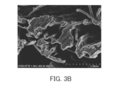
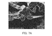
- 1 is a scanning electron microscope (SEM) image of a cross section near the outer surface of the PTFE porous membrane A used in Examples.
- 1 is an SEM image of a cross section near the center in the thickness direction of the PTFE porous membrane A used in Examples.
- SEM scanning electron microscope
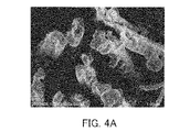
- FIG. 4 is a SEM image of a cross section near the outer surface of the composite substrate of Example 3.
- FIG. 4 is a SEM image of a cross section near the center in the thickness direction of the composite base material of Example 3.
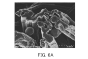
- FIG. 10 is an SEM image of a cross section near the outer surface of the composite substrate of Example 4.
- FIG. 4 is a SEM image of a cross section near the center in the thickness direction of the composite base material of Example 4.
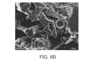
- FIG. 10 is a SEM image of a cross section near the outer surface of the PTFE porous membrane A on which the underlayer of Example 5 was formed.
- FIG. 10 is a SEM image of a cross section near the center in the thickness direction of the PTFE porous membrane A having the underlayer of Example 5 formed thereon.
- FIG. 10 is a SEM image of a cross section near the center in the thickness direction of the PTFE porous membrane A having the underlayer of Example 5 formed thereon.
- FIG. 10 is an SEM image of a cross section near the outer surface of the composite substrate of Example 5.
- FIG. 10 is an SEM image of a cross section near the center in the thickness direction of the composite substrate of Example 5.
- FIG. 10 is a graph showing the results of microscopic Raman spectroscopic measurement of the cross section of the PTFE porous membrane A, the cross section of the PTFE porous membrane A having the base layer formed thereon, and the cross section of the composite substrate in Example 5.
- FIG. 1 is an image mapping the peak at 731 cm ⁇ 1 for the cross section of the PTFE porous membrane A used in Example 5, based on the results of microscopic Raman spectroscopy.
- FIG. 1 is an image mapping the peak at 731 cm ⁇ 1 for the cross section of the PTFE porous membrane A used in Example 5, based on the results of microscopic Raman spectroscopy.
- FIG. 10 is an image mapping the peak at 1580 cm ⁇ 1 for the cross section of the PTFE porous membrane A on which the underlayer was formed in Example 5, based on the results of microscopic Raman spectroscopy.
- FIG. 10 is an image mapping the peak at 1580 cm ⁇ 1 for the cross section of the composite substrate of Example 5, based on the results of microscopic Raman spectroscopy.
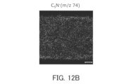
- FIG. 10 is an image mapping the results of time-of-flight secondary ion mass spectrometry (TOF-SIMS) of the cross section of the PTFE porous membrane A on which the underlayer was formed in Example 5.
- TOF-SIMS time-of-flight secondary ion mass spectrometry
- FIG. 10 is an image mapping the results of TOF-SIMS for the cross section of the PTFE porous membrane A on which the underlayer of Example 5 was formed.
- FIG. FIG. 10 is an image mapping the results of TOF-SIMS for the cross section of the PTFE porous membrane A on which the underlayer of Example 5 was formed.
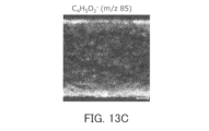
- FIG. FIG. 10 is an image mapping the results of TOF-SIMS for the cross section of the composite substrate of Example 5.
- FIG. 10 is an image mapping the results of TOF-SIMS for the cross section of the composite substrate of Example 5.
- FIG. 10 is an image mapping the results of TOF-SIMS for the cross section of the composite substrate of Example 5.
- FIG. 10 is an image mapping the results of TOF-SIMS for the cross section of the composite substrate of Example 5.
- the composite substrate according to the first aspect of the present invention is a porous substrate comprising a first organic material; a base layer covering the surface of the pores of the porous substrate and containing a second organic material; with At least one of (a) the underlying layer includes a polymerization initiation group and (b) the underlying layer is bound to a polymer chain is established.
- the second organic material contains a polymer having structural units derived from catecholamines.
- the polymer contains the polymerization initiation group, and (b1) the polymer is bonded to the polymer chain. At least one of is established.
- the catecholamines are represented by the following formula (1).
- R 1 to R 4 are each independently a hydrogen atom or an optional substituent
- Z is represented by the following formula (2) or (3).
- X - is any anion
- R 5 is a hydrogen atom or an arbitrary substituent.
- the optional substituents in R 1 and R 2 are hydroxyl group, carboxyl group or halogen group.
- Z is represented by the following formula (4).
- R 6 is a divalent hydrocarbon group which may have a substituent
- A is the polymerization initiation group.
- the polymerization initiation group is at least one selected from the group consisting of halogen groups and nitroxide groups. .
- the polymer chain contains a structural unit derived from a radically polymerizable monomer.
- the first organic material contains a hydrophobic resin.
- the first organic material contains a fluororesin.
- the first organic material contains polytetrafluoroethylene.
- the base layer includes a first layer in direct contact with the surface of the hole, a second layer covering the one layer; At least one of (a2) the second layer includes a polymerization initiation group, and (b2) the second layer is bound to a polymer chain is established.
- the method for producing a composite substrate according to the thirteenth aspect of the present invention comprises: A method for manufacturing a composite substrate according to any one of the first to twelfth aspects, comprising: The manufacturing method is The method includes step (I) of forming the underlayer containing the polymerization initiation group so as to cover the surface of the pores of the porous substrate.
- the step (I) includes: step (i) of contacting the surfaces of the pores with a solution containing catecholamines; a step (ii) of allowing the polymerization reaction of the catecholamines to proceed; including.
- the catecholamines contain the polymerization initiation group.
- the step (i) includes a step (ia) of filling a liquid containing water into the hole; a step (ib) of adding the catecholamines to the liquid; including.
- the porous substrate having the pores filled with alcohol is brought into contact with water, thereby The inside of the holes is filled with the liquid.
- ultrasonic treatment is performed in the step (ia).
- the liquid further contains a surfactant.
- the polymerization reaction of the catecholamines is allowed to proceed by adjusting the pH of the solution.
- the production method according to any one of the thirteenth to twentieth aspects includes contacting a group of monomers with the underlayer containing the polymerization initiation group, and Further comprising step (II) of forming said polymer chain by polymerizing groups.
- composite substrates 10A and 10B of this embodiment comprise a porous substrate 1 containing a first organic material and an underlying layer 2 containing a second organic material.
- the underlayer 2 covers the surface 1a of the pores of the porous substrate 1 .
- the underlayer 2 may entirely cover the surface 1a of the hole, or may partially cover the surface 1a of the hole.
- at least one of (a) the underlying layer 2 contains a polymerization initiation group and (b) the underlying layer 2 is bound to the polymer chains 3 is established.
- FIG. 1A shows an example of a composite substrate 10A that satisfies requirement (a).
- FIG. 1B shows an example of a composite substrate 10B that satisfies requirement (b).
- FIGS. 1A and 1B are partially enlarged cross-sectional views of the pores of the porous substrate 1.
- the pore surface 1 a is, in other words, the surface facing the internal pores of the porous substrate 1 .
- the surface defining the outer shape of the porous substrate 1 is sometimes referred to as the outer surface of the porous substrate 1 in order to distinguish it from the surface 1a.
- the underlayer 2 may cover not only the surface 1a of the pores but also the outer surface of the porous substrate 1 .
- Composite substrate 10A does not include, for example, polymer chains 3 bound to underlying layer 2 .
- the first organic material contained in the porous substrate 1 examples include resins such as hydrophobic resins and hydrophilic resins.
- the porous substrate 1 may contain a hydrophobic resin.
- hydrophobic resin means a resin having a water content of 0.1% or less
- hydroophilic resin means a resin having a water content of more than 0.1%.
- moisture content means the ratio of the difference between the weight of the resin when it is wet and the weight of the resin when it is dry to the weight of the resin when it is dry.
- the "weight of the resin when dried” is a value obtained by weighing the resin when the resin is left to stand in an atmosphere of 60°C for 2 hours or more to dry.
- Weight of resin when wet is a value obtained by weighing the above-mentioned dried resin after immersing the resin in water kept at 30°C for 2 hours or longer. The operation of “drying the resin by leaving it in an atmosphere of 60° C. for 2 hours or longer” is performed until the weight of the resin does not change.
- the time for which the resin is allowed to stand is not particularly limited as long as it is 2 hours or more and the weight of the resin does not change, and it may be 2 hours or 3 hours.
- the state in which the weight of the resin does not change is, for example, the weight W t of the resin when the resin is left to stand for a predetermined time (t hours) of 2 hours or more in an atmosphere of 60 ° C.
- Hydrophobic resins include, for example, polytetrafluoroethylene (PTFE), polyvinylidene fluoride (PVDF), ethylene-polytetrafluoroethylene copolymer (ETFE), perfluoroalkoxyalkane (PFA) and other fluorine resins; polyethylene ( PE), polyolefin resins such as polypropylene (PP); polystyrene resins; rubber-based resins;
- the porous substrate 1 preferably contains a fluororesin, particularly PTFE, as the hydrophobic resin.
- hydrophilic resins examples include polyimide resins; polyetherimide resins; polyetheretherketone resins; polyethersulfone resins; polyethylene terephthalate resins; polycarbonate resins; ) (meth)acrylic resins such as methyl acrylate; and polyvinyl alcohol resins such as polyvinyl alcohol (PVA) and ethylene-vinyl alcohol copolymer (EVOH).
- (meth)acrylic acid means acrylic acid and/or methacrylic acid.
- the first organic material may be composed only of a hydrophobic resin, may be composed only of a hydrophilic resin, or may contain both a hydrophobic resin and a hydrophilic resin.
- the porous substrate 1 may contain the first organic material, particularly a fluororesin such as PTFE, as a main component, and preferably consists essentially of the first organic material.
- the term “main component” means a component contained in the porous substrate 1 in the largest amount by weight. "Consisting essentially of” means excluding other ingredients that modify the essential characteristics of the referenced material.
- the porous substrate 1 may contain impurities in addition to the first organic material.
- the porous substrate 1 may further contain an inorganic material such as silicon, glass, metal, metal oxide, or alloy together with the first organic material.
- the shape of the porous substrate 1 includes, for example, a film shape and a particulate shape.
- a specific form of the membranous porous substrate 1 is a film, a woven fabric, a nonwoven fabric, or the like. Fibers comprising woven fabrics, non-woven fabrics, etc. may comprise a core and a shell covering the core.
- the core may be made of a material other than hydrophobic resin (hydrophilic resin, inorganic material, etc.), and the shell may be made of hydrophobic resin.
- a specific example of the porous substrate 1 is a PTFE porous membrane.
- the thickness of the porous substrate 1 is, for example, 1 to 1000 ⁇ m.
- the shape of the pores included in the porous substrate 1 is not particularly limited.
- the porous substrate 1 may have continuous pores formed continuously in a three-dimensional shape, or may have independent pores.
- the porous substrate 1 may have through-holes penetrating through the porous substrate 1 . As an example, the through holes may extend in the thickness direction of the porous substrate 1 .
- the average pore size of the porous substrate 1 is, for example, 0.01 to 100 ⁇ m.
- the average pore diameter of the porous substrate 1 can be measured by a method based on ASTM (American Society for Testing and Materials) F316-86.
- the porosity of the porous substrate 1 is, for example, 10% to 90%.
- the porosity of the porous substrate 1 can be calculated by substituting the weight W (g), volume V (cm 3 ) and true density D (g/cm 3 ) of the porous substrate 1 into the following formula.
- Porosity (%) ⁇ 1-(W/(V D)) ⁇ x 100
- the BET Brunauer-Emmett-Teller specific surface area by nitrogen gas adsorption is not particularly limited, and is, for example, 0.01 to 100 m 2 /g.
- the base layer 2 contains a polymerization initiation group.
- the polymerization initiation group is, for example, at least one selected from the group consisting of halogen groups and nitroxide groups. These polymerization initiating groups are suitable for initiating radical polymerization, especially living radical polymerization.
- a halogen group is for example F, Cl, Br or I, preferably Br.
- the second organic material contained in the underlying layer 2 contains, for example, a polymer P having structural units derived from catecholamines.
- catecholamines means compounds and/or derivatives thereof having a catechol group and an amino group.
- the requirement (a1) that the polymer P contains a polymerization initiation group may be satisfied.
- the polymer P having structural units derived from catecholamines tends to strongly adhere to the surface of the porous substrate 1 regardless of the type of the porous substrate 1 .
- Catecholamines are represented, for example, by the following formula (1).
- R 1 to R 4 are each independently hydrogen atoms or optional substituents.
- Optional substituents for R 1 and R 2 are not particularly limited and are, for example, hydroxyl groups, carboxyl groups or halogen groups.
- the halogen group is preferably a bromo group.
- both R 1 and R 2 may be hydrogen atoms.
- R 1 may be a hydroxyl group and R 2 may be a hydrogen atom.
- R 3 and R 4 are not particularly limited, and are, for example, acyl groups optionally having substituents.
- An acyl group is represented by -COR a .
- R a is, for example, a hydrocarbon group optionally having a substituent.
- the hydrocarbon group may be linear or branched.
- the number of carbon atoms in the hydrocarbon group is not particularly limited, and is, for example, 1-10, preferably 1-5.
- Examples of the hydrocarbon group include methyl group, ethyl group, propyl group and the like, preferably isopropyl group.
- Substituents of the hydrocarbon group include, for example, polymerization initiation groups such as halogen groups.
- R7 is a divalent hydrocarbon group which may have a substituent.
- the divalent hydrocarbon group may be linear or branched.
- the number of carbon atoms in the divalent hydrocarbon group is not particularly limited, and is, for example, 1-10, preferably 1-5.
- the divalent hydrocarbon group includes a methylene group, an ethylene group, a propane-1,3-diyl group, a propane-2,2-diyl group and the like, preferably a propane-2,2-diyl group.
- a divalent hydrocarbon group may not have a substituent.
- R 7 is preferably a propane-2,2-diyl group.
- A is a polymerization initiation group. Examples of the polymerization initiation group include those described above. A is preferably a bromo group.
- R 3 and R 4 are typically hydrogen atoms. However, at least one selected from the group consisting of R 3 and R 4 may be a substituent represented by the above formula (5).
- Z is represented by the following formula (2) or (3).
- X ⁇ is any anion.
- X ⁇ is not particularly limited as long as it forms a salt with a quaternary ammonium cation, and is, for example, a halide ion or a carboxylate ion.
- Halide ions include, for example, fluoride ions, chloride ions, bromide ions, and iodide ions.
- Carboxylate ions include, for example, tartaric acid ions.
- X ⁇ is preferably chloride ion.
- R 5 is a hydrogen atom or any substituent.
- the optional substituent in R 5 is not particularly limited, and examples thereof include an optionally substituted hydrocarbon group or an optionally substituted acyl group.
- the hydrocarbon group may be linear or branched.
- the number of carbon atoms in the hydrocarbon group is not particularly limited, and is, for example, 1-10, preferably 1-5.
- Examples of the hydrocarbon group include methyl group, ethyl group, propyl group and the like, preferably methyl group.
- Substituents of the hydrocarbon group include, for example, polymerization initiation groups such as halogen groups.
- R 5 the acyl group is represented by —COR a .
- R a is, for example, a hydrocarbon group optionally having a substituent. Examples of the hydrocarbon group include those described above.
- Equation (4) is a more detailed representation of Equation (3) above.
- R 6 is a divalent hydrocarbon group which may have a substituent.
- the divalent hydrocarbon group may be linear or branched.
- the number of carbon atoms in the divalent hydrocarbon group is not particularly limited, and is, for example, 1-10, preferably 1-5.
- the divalent hydrocarbon group includes a methylene group, an ethylene group, a propane-1,3-diyl group, a propane-2,2-diyl group and the like, preferably a propane-2,2-diyl group.
- a divalent hydrocarbon group may not have a substituent.
- A is a polymerization initiation group.
- examples of the polymerization initiation group include those described above.
- A is preferably a bromo group.
- Catecholamines may be represented by the following formula (6).
- the catecholamines of formula (6) correspond to compounds of formula (1) in which R 3 and R 4 are hydrogen atoms.
- R 1 , R 2 and Z are the same as in formula (1).
- Specific examples of catecholamines represented by formula (6) include formulas (C1) to (C9) below.
- Formulas (C1) to (C2) represent dopamine derivatives.
- Formulas (C3)-(C5) represent norepinephrine derivatives.
- Formula (C6) represents epinephrine.
- Formula (C7) represents levodopa.
- Formula (C8) represents droxidopa.
- the dopamine hydrochloride of formula (C1) is sometimes referred to herein as DA, and the dopamine derivative of formula (C2) is sometimes referred to as ATRP-DA.
- the norepinephrine hydrochloride of formula (C3) is sometimes referred to as NE, and the norepinephrine derivative of formula (C4) is sometimes referred to as ATRP-NE.
- the catecholamines may be reaction products of the compound represented by the above formula (6) and other compounds.
- Other compounds include, for example, compound F having a polymerization initiation group and a functional group capable of reacting with catecholamines.
- Functional groups capable of reacting with catecholamines are typically acyl halide groups.
- Compound F is represented, for example, by the following formula (7).
- X 1 is a halogen group, preferably a bromo group.
- R 8 is a divalent hydrocarbon group optionally having a substituent. Hydrocarbon groups for R 8 include those described above for R 7 .
- R 8 is preferably a propane-2,2-diyl group.
- A is a polymerization initiation group. Examples of the polymerization initiation group include those described above.
- A is preferably a bromo group.
- a specific example of compound F is 2-bromoisobutyryl bromide (BiBB).
- reaction product of the compound represented by formula (6) and compound F represented by formula (7) is represented by, for example, the following formula (8).
- R 1 and R 2 are the same as in formula (6).
- R 11 is a hydrogen atom, a substituent contained in Z in formula (6), or a group represented by the general formula —C( ⁇ O)—R 8 —A.
- Catecholamines are not limited to those represented by formula (1).
- the catecholamines may be methyldopa represented by the following formula (D1).
- the above-mentioned catecholamines may be used singly or in combination of two or more.
- the catecholamines preferably contain at least one selected from the group consisting of dopamine derivatives and norepinephrine derivatives, and more preferably contain at least one of the compounds represented by formulas (C1) to (C4).
- Catecholamines can form a polymer P, for example, by self-oxidative polymerization in the presence of oxygen atoms.
- catecholamines represented by formula (1) undergo a polymerization reaction represented by the following reaction formula (S1).
- reaction formula (S1) the indole derivative represented by formula (E1) is an intermediate of the polymerization reaction.
- Reaction Formula (S1) a polymer P having structural units (p1) derived from catecholamines is formed. That is, the polymer P may contain the following structural unit (p1).
- R 1 to R 4 are the same as in formula (1).
- R12 is a hydrogen atom or a substituent corresponding to R5 .
- a polymer P containing a polymerization initiation group can be produced by using catecholamines containing a polymerization initiation group.
- the polymerization reaction proceeds at the 4-position and 7-position of the indole ring.
- R 2 is a hydrogen atom in the indole derivative (E1)
- the polymerization reaction may proceed even at the 2-position of the indole ring in the structural unit (p1). At this time, the polymer P has a three-dimensional crosslinked structure.
- the polymer P may contain structural units derived from catecholamines as a main component, and preferably consists essentially of structural units derived from catecholamines.
- the underlayer 2 may contain the polymer P as a main component, and preferably consists essentially of the polymer P only. However, the underlying layer 2 may contain impurities in addition to the polymer P.
- the thickness of the underlying layer 2 is not particularly limited, and is, for example, 1 to 200 nm.
- the method for manufacturing the composite substrate 10A includes a step (I) of forming an underlayer 2 containing a polymerization initiation group so as to cover the pore surfaces 1a of the porous substrate 1 .
- the step (I) includes, for example, a step (i) of bringing a solution S containing catecholamines into contact with the surface 1a of the pores of the porous substrate 1, and a step (ii) of allowing the polymerization reaction of the catecholamines to proceed. .
- the step (i) includes a step (ia) of filling the inside of the pores of the porous substrate 1 with a liquid L containing water, and a step (ib) of adding catecholamines to the liquid L.
- the porous substrate 1 and alcohol are brought into contact before step (ia).
- the porous substrate 1 is immersed in alcohol.
- Alcohols are preferably lower alcohols such as methanol and ethanol.
- the alcohol permeates into the pores of the porous substrate 1, thereby filling the pores with the alcohol.
- the inside of the holes is filled with alcohol.
- Ultrasonic treatment may be performed while the porous substrate 1 and alcohol are in contact with each other. By performing ultrasonic treatment, the alcohol can easily penetrate into the pores of the porous substrate 1 .
- step (ia) the porous substrate 1 whose pores are filled with alcohol is brought into contact with water.
- the water is mixed with the alcohol while permeating into the pores of the porous substrate 1 .
- the liquid L containing water is formed inside the hole, and the inside of the hole can be filled with the liquid L.
- the liquid L is, for example, a mixed liquid of alcohol and water.
- the content of water in liquid L is not particularly limited, and is, for example, 50 vol % to 70 vol %.
- ultrasonic treatment may be performed while the porous substrate 1 is in contact with water. Water can easily penetrate into the pores of the porous substrate 1 by performing the ultrasonic treatment. Conditions for ultrasonic treatment are not particularly limited. Sonication may be performed, for example, for one hour or longer.
- a surfactant may be added together with water to the porous substrate 1 whose pores are filled with alcohol. Surfactants allow water to more easily penetrate into the pores of the porous substrate 1 .
- the liquid L formed by this operation further contains a surfactant.
- the surfactant is not particularly limited, and for example, a fluorosurfactant can be used.
- the method of filling the inside of the pores of the porous substrate 1 with the liquid L is not limited to the method described above. As long as the inside of the pores of the porous substrate 1 can be filled with the liquid L, it is not always necessary to prepare the porous substrate 1 in which the inside of the pores is filled with alcohol before step (ia).
- the pores of the porous substrate 1 are filled with the liquid L by bringing the liquid L containing the surfactant into contact with the porous substrate and then performing ultrasonic treatment. do.
- the liquid L may be alcohol-free and may be a mixture of water and a surfactant.
- catecholamines are added to liquid L in step (ib). Thereby, the catecholamines are dissolved in the liquid L to form a solution S.
- the catecholamines represented by the formula (8) can be synthesized by reacting the compound represented by the formula (6) with the compound F represented by the formula (7). .
- This reaction can be carried out, for example, using triethylamine in an organic solvent such as N,N-dimethylformamide (DMF).
- DMF N,N-dimethylformamide
- This reaction liquid may be added to the liquid L described above. Even in this case, the solution S is formed by mixing the reaction liquid and the liquid L. Since the liquid L is filled inside the pores of the porous substrate 1, the solution S obtained by adding catecholamines to the liquid L contacts the surface 1a of the pores.
- the catecholamines contain, for example, a polymerization initiation group.
- a polymer P containing a polymerization initiation group can be produced by the polymerization reaction of step (ii).
- catecholamines containing no polymerization initiation group may be added to the liquid L together with catecholamines containing a polymerization initiation group.
- the molar ratio of catecholamines containing a polymerization initiating group to catecholamines not containing a polymerization initiating group is not particularly limited, and is, for example, 2:8 to 8:2.
- step (ii) the polymerization reaction of catecholamines is allowed to proceed.
- the polymerization reaction of the catecholamines proceeds while the catecholamines contained in the solution S are in contact with the surface 1a of the pores.
- a polymer P containing a polymerization initiation group is formed on the surface 1a of the pores, and the underlying layer 2 is obtained.
- the polymerization reaction of the catecholamines proceeds on the outer surface of the porous substrate 1, so that the base layer 2 may be formed on the outer surface as well.
- the composite substrate 10A can be obtained by forming the underlayer 2 containing the polymerization initiation group on the surface 1a of the holes.
- the polymerization reaction of catecholamines can be advanced by adjusting the pH of solution S.
- the pH of the solution S can be adjusted with a buffer containing trishydroxymethylaminomethane (Tris), for example.
- the buffer may be Tris-HCl buffer (TRIS-HCl).
- a buffer may be added to liquid L before performing step (ib). In this case, when the catecholamines are added to the liquid L containing the buffer in step (ib), the pH of the resulting solution S tends to be adjusted appropriately.
- the polymerization reaction of catecholamines can be performed at room temperature (23° C.), for example.
- the porous substrate 1 contains the first organic material, even if the porous substrate 1 and the liquid L (or the solution S) containing water are simply brought into contact, the liquid L The inside of the pores of the porous substrate 1 is hardly filled.
- the porous substrate 1 contains a hydrophobic resin, it is difficult to fill the liquid L inside the pores of the porous substrate 1 . According to the studies of the present inventors, even if the method disclosed in Patent Document 1 is applied to the porous substrate as it is, the underlying layer cannot be formed inside the pores of the porous substrate.
- composite base material 10B that satisfies the requirement (b) will be described.
- underlayer 2 is bonded to polymer chains 3 .
- the composite substrate 10B is the same as the composite substrate 10A. Therefore, elements common to the composite substrate 10A described above and the composite substrate 10B of the present embodiment are denoted by the same reference numerals, and description thereof may be omitted. That is, the descriptions of the respective embodiments below can be applied to each other as long as they are not technically inconsistent. Furthermore, each embodiment may be combined with each other unless it is technically inconsistent.
- the polymer chain 3 can be produced, for example, by a polymerization reaction of a group of monomers starting from a polymerization initiation group contained in the underlayer 2 of the composite substrate 10A, specifically the polymer P.
- the requirement (b1) that the polymer P is bound to the polymer chain 3 may be satisfied.
- the underlayer 2, especially the polymer P may not contain a polymerization initiation group.
- the polymer chains 3 are, for example, attached to the surface 2a of the underlayer 2 and extend in the thickness direction of the underlayer 2 .
- the polymer chains 3 are present inside the pores of the porous substrate 1 .
- the underlayer 2 also covers the outer surface of the porous substrate 1 , some of the polymer chains 3 may exist on the outer surface of the porous substrate 1 .
- the group of monomers for forming the polymer chain 3 includes, for example, radically polymerizable monomers.
- the polymer chain 3 contains structural units derived from radically polymerizable monomers.
- radically polymerizable monomers include (meth)acrylic esters, (meth)acrylic acid, (meth)acrylamides, styrene derivatives, olefins, halogenated olefins, vinyl esters, vinyl alcohols and nitriles.
- R 13 is a hydrogen atom or a methyl group.
- R 14 is a hydrocarbon group optionally having a substituent.
- the number of carbon atoms in the hydrocarbon group is not particularly limited, and is, for example, 1-20, preferably 1-15.
- the hydrocarbon group may be linear or branched.
- a substituent of the hydrocarbon group may contain a heteroatom such as a nitrogen atom, an oxygen atom, or a halogen atom.
- Substituents for the hydrocarbon group include, for example, a hydroxyl group, an amino group, an alkoxy group, and a halogen group.
- R 14 may be represented by the following formula (10). —(R 15 —O) n —H (10)
- R 15 is an alkylene group having 1 to 8 carbon atoms, preferably an ethylene group. In formula (10), when multiple R 15 are present, the multiple R 15 may be the same or different. In formula (10), n is an integer of 1 or greater. The upper limit of n is not particularly limited, and is 200, for example.
- R 14 may be a fluorine-containing hydrocarbon group.
- the fluorine-containing hydrocarbon group may be branched, but preferably linear.
- a fluorine-containing hydrocarbon group may be represented, for example, by the following formula (11). -R16 -Rf (11)
- R 16 is an alkylene group having 1 to 8 carbon atoms, preferably an ethylene group.
- Rf is a perfluoroalkyl group having 1 to 12 carbon atoms. In Rf, the number of carbon atoms in the perfluoroalkyl group is preferably 1 to 6, more preferably 1 to 4, from the viewpoint of environmental regulations regarding fluorine compounds.
- R 14 in formula (9) include a polyethylene glycol group, a 1H,1H,2H,2H-heptadecafluoro-n-decyl group, and a 1H,1H,2H,2H-tridecafluoro-n-octyl group. , methyl group, ethyl group, butyl group, t-butyl group, hexyl group, 2-ethylhexyl group, octyl group, 2-hydroxyethyl group, 2-[2-(2-methoxyethoxy)ethoxy]ethyl group, dimethylamino An ethyl group etc. are mentioned.
- Examples of (meth)acrylamide include (meth)acrylamide, N-isopropyl(meth)acrylamide, dimethylaminopropyl(meth)acrylamide, (meth)acrylamidopropyltrimethylammonium chloride, and (meth)acrylamido-2-methylpropanesulfonic acid. etc.
- styrene derivatives include styrene, ⁇ -methylstyrene, vinylbenzyl chloride, butoxystyrene, vinylaniline, sodium styrenesulfonate, vinylbenzoic acid, vinylpyridine, dimethylaminomethylstyrene, vinylbenzyltrimethylammonium chloride, and the like.
- olefins examples include ethylene, propylene, butadiene, butene, and isoprene.
- halogenated olefins include, for example, vinyl chloride, vinylidene chloride, tetrafluoroethylene, and the like.
- vinyl esters examples include vinyl acetate and vinyl propionate.
- Vinyl alcohols include, for example, saponified vinyl esters described above.
- Nitriles include, for example, (meth)acrylonitrile.
- the monomer group may contain one or more of the above monomers.
- the monomer group contains, for example, a radically polymerizable monomer as a main component, and preferably consists essentially of a radically polymerizable monomer.
- the thickness of this layer is not particularly limited, and is, for example, 10 nm to 10 mm, may be 1 mm or less, may be 100 nm or less, or may be 50 nm or less.
- the molecular weight of polymer chain 3 can be easily controlled. For example, it is possible to suppress variations in molecular weight among the plurality of polymer chains 3 .
- the molecular weight distribution (ratio of weight-average molecular weight to number-average molecular weight) of the plurality of polymer chains 3 is not particularly limited, and is, for example, 1.5 or less.
- the molecular weight per polymer chain 3 is not particularly limited, and is, for example, 500 to 500,000.
- the resulting polymer chain 3 has a polyethylene glycol group.
- the hydrophilicity of the porous substrate 1 tends to be greatly improved.
- the properties that can be imparted to the porous substrate 1 are not limited to hydrophilicity. According to this embodiment, various properties can be imparted to the porous substrate 1 according to the type of the polymer chains 3 .
- the method for producing the composite base material 10B includes, for example, contacting a group of monomers with the underlayer 2 containing the polymerization initiation group in the composite base material 10A described above, and polymerizing the monomer group by the polymerization initiation group, thereby forming the polymer chain 3.
- the step (II) of forming is included.
- the polymerization of the monomer group by the polymerization initiation group is, for example, radical polymerization, preferably living radical polymerization.
- Living radical polymerization includes atom transfer radical polymerization (ATRP), nitroxide mediated radical polymerization (NMP) and the like, preferably ATRP.
- ATRP atom transfer radical polymerization
- NMP nitroxide mediated radical polymerization
- the polymerization initiation group is preferably a halogen group.
- NMP the polymerization initiation group is preferably a nitroxide group.
- the polymerization of the monomer group by the polymerization initiating group can be performed in detail by the following method.
- a solution B containing a group of monomers is prepared.
- solution B may contain a transition metal complex as a catalyst.
- a transition metal complex contains a transition metal and a ligand.
- transition metals include metals of Groups 7 to 11 of the periodic table, preferably ruthenium, copper, iron, nickel, rhodium, palladium, rhenium and the like, and particularly preferably copper.
- ligands include 1,1,4,7,10,10-hexamethyltriethylenetetramine, tris[2-(dimethylamino)ethyl]amine, N,N,N',N'',N ''-Pentamethyldiethylenetriamine, triphenylphosphine, tributylphosphine, chlorine, bromine, iodine, indene, fluorene, 2,2'-bipyridine, 4,4'-diheptyl-2,2'-bipyridine, 1,10-phenanthroline , and Spartein.
- a transition metal complex can be prepared in solution B by adding the ligand and the compound containing the transition metal to solution B separately.
- the solution B may further contain a polymerization initiator.
- the polymerization initiator is not particularly limited as long as it is a compound having the polymerization initiation group described above, and is, for example, 2-bromo-N-hexyl-2-methylpropanamide.
- polymerization of the monomer group proceeds also with the polymerization initiator.
- the molecular weight (number-average molecular weight and weight-average molecular weight) and molecular weight distribution of the polymer obtained by growing the monomer group from the polymerization initiator are comparable to those of polymer chain 3 . Therefore, the molecular weight and molecular weight distribution of the polymer obtained from the polymerization initiator may be measured, and the obtained values may be regarded as the molecular weight and molecular weight distribution of the polymer chain 3 .
- Solution B may or may not further contain a solvent.
- the solvent can be appropriately selected depending on the composition of the monomer group, polymerization conditions, etc. Examples include water; alcohols such as isopropanol and 1,1,1,3,3,3-hexafluoro-2-propanol; ethers such as; ketones such as acetone.
- the ratio of the weight of the monomer group to the total weight of the solvent and the weight of the monomer group is not particularly limited, and is, for example, 10 wt % to 100 wt %.
- the composite base material 10A is immersed in the solution B.
- the solution B penetrates into the pores of the porous substrate 1 and the monomer group contained in the solution B comes into contact with the underlying layer 2 .
- freezing and degassing may be performed while the porous substrate 1 is immersed in the solution B.
- the monomer group can be polymerized by the polymerization initiation groups contained in the underlayer 2 .
- the heating temperature of solution B can be appropriately adjusted according to the composition of solution B, and is, for example, 30°C to 120°C.
- the heating time of solution B is not particularly limited, and is, for example, 0.5 to 48 hours.
- Polymerization of the monomer group is preferably carried out in an inert gas atmosphere such as nitrogen gas.
- radicals are generated by irradiating the surface of a base material with energy rays or plasma, and the radicals are used to polymerize a monomer group.
- the radicals are generated only in the irradiated portions, and radicals are hardly generated inside the porous substrate. Therefore, in order to generate radicals on the surfaces of the pores inside the porous substrate, energy rays having relatively high energy, such as electron beams and gamma rays, are used.
- the polymer chains 3 can be introduced into the surface 1a of the pores of the porous substrate 1 without using energy rays having high energy. can be done.
- the material of the porous base material 1 is hardly restricted.
- the polymer chains 3 can be easily introduced into the pore surfaces 1a of the porous substrate 1.
- the underlayer 2 most of the surface 1a of the pores of the porous substrate 1 is suppressed from directly contacting the monomer group. 1 and swelling of the porous substrate 1 can be suppressed. Thereby, a change in the structure of the porous substrate 1 can be suppressed.
- the production method of the present embodiment is suitable for controlling the properties by introducing the polymer chains 3 to the surface 1a of the pores of the porous substrate 1 while suppressing changes in the structure of the porous substrate 1 itself. .
- Penetration of the monomer may also change the structure of the porous substrate, eg, the shape of the pores.
- Polymerization of the monomer that permeates the porous substrate may result in insufficient introduction of polymer chains to the surface of the porous substrate. Since the manufacturing method of the present embodiment uses the underlying layer 2, these problems are less likely to occur.
- the base layer 2 contains the second organic material.
- the underlayer 2 tends to have relatively high durability against acids and bases, compared to, for example, underlayers made of inorganic materials. Therefore, the composite base material 10B provided with this base layer 2 may be used in a wide range of applications.
- TEM transmission electron microscope
- SEM-EDX scanning electron microscope-energy dispersive X-ray spectroscopy
- TOF-SIMS time-of-flight secondary ion mass spectrometry
- XPS X-ray photoelectron spectroscopy
- the base layer 2 may be composed of multiple layers. As shown in FIGS. 2A and 2B, in composite substrates 11A and 11B according to modifications, the base layer 2 has a first layer 5 and a second layer 6 .
- the first layer 5 is in direct contact with the pore surfaces 1 a of the porous substrate 1 .
- the second layer 6 covers the first layer 5 and is in direct contact with the first layer 5, for example.
- at least one of (a2) the second layer 6 includes a polymerization initiation group and (b2) the second layer 6 is bound to the polymer chain 3 is established.
- FIG. 2A shows an example of a composite substrate 11A that satisfies requirement (a2).
- FIG. 2B shows an example of a composite substrate 11B that satisfies requirement (b2).
- the first layer 5 has, for example, the same composition as the base layer 2 of the composite substrate 10A described above, except that it does not contain a polymerization initiation group.
- the first layer 5 is formed by the same method as the method for producing the base layer 2 of the composite base material 10A described above, except that only catecholamines containing no polymerization initiation group are added to the liquid L in the above step (ib). can be made.
- catecholamines containing no polymerization initiation group include the compound (DA) represented by the formula (C1) and the compound (NE) represented by the formula (C3).
- the first layer 5 tends to have better formability than the underlayer 2 of the composite substrate 10A. Therefore, the first layer 5 can easily cover the entire surface 1a of the pores of the porous substrate 1 .
- the second layer 6 of the composite base material 11A has, for example, the same composition as the underlying layer 2 of the composite base material 10A described above. That is, the second layer 6 may contain a polymer P containing a polymerization initiation group. The composition of the second layer 6 may be the same as or different from that of the first layer 5 except that it contains a polymerization initiation group.
- the second layer 6 can be produced by the same method as the method for producing the base layer 2 of the composite substrate 10A described above. In this embodiment, the second layer 6 tends to be easily formed over the first layer 5 because the compositions of the first layer 5 and the second layer 6 are relatively similar.
- the polymer chain 3 of the composite base material 11B can be produced, for example, by a polymerization reaction of a monomer group starting from the polymerization initiation group contained in the second layer 6 of the composite base material 11A, specifically the polymer P.
- the polymer P contained in the second layer 6 may bond with the polymer chains 3 .
- the second layer 6, particularly the polymer P contained in the second layer 6, may not contain a polymerization initiation group.
- ATRP-DA compound represented by formula (C2) was synthesized by the method described in Polymer, 2011, Vol. 52, p. 2141-2149.
- a PTFE porous membrane A (average pore size: 3.0 ⁇ m, porosity: 85%, thickness: 70 ⁇ m) was prepared as a porous substrate.
- the PTFE porous membrane A was immersed in methanol and subjected to ultrasonic treatment for 10 minutes, thereby filling the inside of the pores of the PTFE porous membrane A with methanol.
- distilled water was slowly added to the PTFE porous membrane A.
- the inside of the pores of the PTFE porous membrane A was filled with the aqueous methanol solution (liquid L).
- aqueous methanol solution liquid L
- Tris-HCl buffer solution Tris-HCl
- the concentration of Tris-HCl in the aqueous methanol solution was adjusted to 10 mM.
- dopamine hydrochloride (DA, manufactured by Tokyo Chemical Industry Co., Ltd.) and ATRP-DA were added in a molar ratio of 5:5 to an aqueous methanol solution, and a polymerization reaction was carried out at room temperature (23° C.) for 24 hours.
- Example 1 By the polymerization reaction of DA and ATRP-DA, an underlayer containing a polymerization initiation group (Br) was formed on the outer surface of the PTFE porous membrane A and the surfaces of the pores. Thus, a composite base material of Example 1 was obtained. The formation of the underlayer on the surface of the pores of the PTFE porous membrane A was confirmed by analyzing the cross section of the composite substrate by TEM, SEM-EDX, TOF-SIMS and XPS.
- Example 2 A composite substrate of Example 2 was obtained by the same method as in Example 1, except that DA and ATRP-DA were added to the aqueous methanol solution at a molar ratio of 2:8. As in Example 1, in the composite base material of Example 2, a base layer containing a polymerization initiation group was formed on the outer surface of the PTFE porous membrane A and the surfaces of the pores.
- Example 3 A composite substrate of Example 3 was obtained by the same method as in Example 1, except that DA and ATRP-NE were added to the aqueous methanol solution at a molar ratio of 5:5. As in Example 1, in the composite substrate of Example 3, a base layer containing a polymerization initiation group was formed on the outer surface of the PTFE porous membrane A and the surfaces of the pores.
- Example 4 A composite substrate of Example 4 was obtained by the same method as in Example 1, except that NE and ATRP-DA were added to the aqueous methanol solution at a molar ratio of 5:5. As in Example 1, in the composite base material of Example 4, a base layer containing a polymerization initiation group was formed on the outer surface of the PTFE porous membrane A and the surfaces of the pores.
- the concentration of Tris-HCl in the aqueous methanol solution was adjusted to 10 mM.
- DA was added to the aqueous methanol solution, and a polymerization reaction was carried out at room temperature (23° C.) for 24 hours.
- a polydopamine layer (first layer) was formed on the outer surface of the PTFE porous membrane A and the surface of the pores by the polymerization reaction of DA.
- DA and ATRP-NE were added to an aqueous methanol solution at a molar ratio of 2:8, and a polymerization reaction was carried out at room temperature (23° C.) for 24 hours.
- a second layer containing polymerization initiation groups (Br) was formed on the first layer by the polymerization reaction of DA and ATRP-NE.
- an underlying layer having a laminated structure of the first layer and the second layer was produced.
- a porous film with a base layer formed thereon, a monomer group, a polymerization initiator, a compound containing a transition metal, a ligand, and a solvent were added to the polymerization tube.
- the monomer group consisted of polyethylene glycol methacrylate (PEGMA). 2-bromo-N-hexyl-2-methylpropanamide was used as a polymerization initiator.
- CuCl was used as the compound containing a transition metal.
- N,N,N',N'',N''-pentamethyldiethylenetriamine (PMDETA) was used as a ligand.
- Anisole (PhOMe) was used as a solvent.
- the molar ratio of monomer group, polymerization initiator, compound containing transition metal and ligand was 50/1/1/1.
- the ratio of the weight of the monomer group to the sum of the weight of the solvent and the weight of the monomer group was 50 wt%.
- the inside of the polymerization tube was freeze-degassed three times, and then filled with nitrogen gas.
- the monomer group was then polymerized by heating the polymerization tube to 60°C.
- air was injected into the reaction solution for bubbling.
- the porous membrane was taken out from the inside of the polymerization tube and washed three times with a washing liquid. Acetone was used as the cleaning liquid.
- the composite substrate of Example 5 was obtained by drying the porous membrane in a drying oven at 60° C. for 1 hour.
- Example 6 A composite substrate of Example 6 was obtained by the same method as in Example 5, except that NE and ATRP-DA were used in a molar ratio of 2:8 to form the second layer. As in Example 5, in the composite substrate of Example 6, a base layer bound to polymer chains was formed on the surface of the pores of the PTFE porous membrane A.
- Example 5 was prepared by the same method as in Example 5, except that NE was used to prepare the first layer, and NE and ATRP-NE were used in a molar ratio of 2:8 to prepare the second layer. 7 composite substrates were obtained. As in Example 5, in the composite substrate of Example 7, a base layer bound to polymer chains was formed on the surface of the pores of the PTFE porous membrane A.
- Example 8 First, a fluorosurfactant (Surflon S242, manufactured by AGC Seimi Chemical Co., Ltd.) was added to water to prepare an aqueous solution (liquid L) with a concentration of 0.1% by weight. Porous PTFE membrane A was immersed in liquid L, subjected to ultrasonic treatment for 60 minutes, and allowed to stand for 120 minutes. Next, TRIS-HCl was added to Liquid L. At this time, the concentration of Tris-HCl in liquid L was adjusted to 10 mM. Next, DA and ATRP-DA were added to liquid L at a molar ratio of 5:5, and a polymerization reaction was carried out at room temperature (23° C.) for 24 hours.
- a fluorosurfactant Sudflon S242, manufactured by AGC Seimi Chemical Co., Ltd.
- Example 8 By the polymerization reaction of DA and ATRP-DA, an underlayer containing a polymerization initiation group (Br) was formed on the outer surface of the PTFE porous membrane A and the surfaces of the pores. Thus, a composite base material of Example 8 was obtained.
- TRIS-HCl was diluted with distilled water so that the concentration of Tris-HCl was 10 mM.
- DA and ATRP-DA were added to the resulting solution at a molar ratio of 5:5.
- the PTFE porous membrane A was immersed in this solution, and the polymerization reaction of DA and ATRP-DA was carried out at room temperature (23° C.) for 24 hours.
- the PTFE porous membrane A was washed with water and dried.
- the outer surface and cross section of this PTFE porous membrane A were observed with a transmission electron microscope.
- an underlayer containing a polymerization initiation group (Br) was formed on the outer surface of the PTFE porous membrane A, but no underlayer was formed on the surfaces of the pores.
- TRIS-HCl was diluted with a mixed liquid of methanol and distilled water.
- an underlayer containing a polymerization initiation group (Br) was formed on the outer surface of the PTFE porous membrane A, but no underlayer was formed on the surfaces of the pores.
- Comparative Example 4 Polymerization of DA and ATRP-DA by the same method as in Comparative Example 1, except that a fluorosurfactant was added to a solution of TRIS-HCl diluted with distilled water to a concentration of 0.1% by weight. reacted. As a result, an underlayer containing a polymerization initiation group (Br) was formed on the outer surface of the PTFE porous membrane A, but no underlayer was formed on the surfaces of the pores.
- a fluorosurfactant was added to a solution of TRIS-HCl diluted with distilled water to a concentration of 0.1% by weight.
- 3A to 7B show the PTFE porous membrane A used in the example, the composite base material of Example 3, the composite base material of Example 4, and the PTFE porous membrane formed with the base layer of Example 5.
- 4 shows the results of observing the cross section near the outer surface and the cross section near the center in the thickness direction of A and the composite substrate of Example 5 with a scanning electron microscope (SEM).
- SEM scanning electron microscope
- Example 5 microscopic Raman spectroscopic measurement was performed on the cross section of the PTFE porous membrane A used, the cross section of the PTFE porous membrane A having the underlying layer formed thereon, and the cross section of the composite substrate. The results are shown in FIG. As can be seen from FIG. 8, from the cross section of the PTFE porous membrane A on which the underlayer was formed and the cross section of the composite base material, almost no peaks derived from PTFE were observed, and peaks around 1410 cm -1 and 1580 cm -1 were characteristic. peak was confirmed.
- FIG. 9 is an image mapping the peak at 731 cm ⁇ 1 for the cross section of the PTFE porous membrane A used in Example 5, based on the results of microscopic Raman spectroscopy.
- the peak at 731 cm -1 originates from the CF bond. It can be seen from FIG. 9 that the PTFE porous membrane A is untreated.
- FIG. 10 is an image mapping the peak at 1580 cm ⁇ 1 for the cross section of the PTFE porous membrane A on which the underlayer of Example 5 was formed, based on the results of microscopic Raman spectroscopy.
- FIG. 11 is an image mapping the peak at 1580 cm ⁇ 1 for the cross section of the composite substrate of Example 5, based on the results of microscopic Raman spectroscopy.
- the peak at 1580 cm ⁇ 1 originates from polymers formed from catecholamines. From FIGS. 10 and 11, it can be seen that the underlying layer is uniformly formed on the surfaces of the pores of the PTFE porous membrane A.
- Time-of-flight secondary ion mass spectrometry was performed on the cross section of the PTFE porous membrane A on which the underlayer of Example 5 was formed and the cross section of the composite substrate of Example 5. Images mapping the TOF-SIMS results are shown in FIGS. 12A-13C. As can be seen from FIGS. 12A and 12B, ion species (CN ⁇ and C 5 N ⁇ ) derived from the polymer formed from catecholamines were detected from the cross section of the PTFE porous membrane A on which the underlayer was formed. As can be seen from FIG.
- ion species (Br ⁇ ) derived from the polymerization initiation groups contained in the underlayer were also detected from the cross section of the PTFE porous membrane A on which the underlayer was formed. From FIGS. 12A to 12C, it can be confirmed that the underlayer is introduced into the inside of the PTFE porous membrane A relatively uniformly.
- ionic species CN ⁇ and C 5 N ⁇ ) derived from polymers formed from catecholamines were detected from the cross section of the composite substrate.
- ion species C 4 H 5 O 2 ⁇ ) derived from polymer chains introduced into the underlying layer were also detected from the cross section of the composite substrate. From FIGS. 13A to 13C, it can be confirmed that the underlayer and polymer chains are introduced into the PTFE porous membrane A relatively uniformly.
- the composite substrate of the present invention can be used in various applications such as sound-permeable membranes, gas-permeable membranes, separation membranes, ion-exchange membranes, diaphragms, catalysts, liquid absorbers, medical materials, etc., depending on its function.
Abstract
The present invention provides a new composite base material in which a pore surface of a porous base material is coated with an underlying layer containing an organic material. The composite base material of the present invention is provided with a porous base material containing a first organic material, and an underlying layer coating a pore surface of the porous base material and containing a second organic material. In the composite base material, at least one of (a) the underlying layer contains a polymerization initiating group and (b) the underlying layer is bound to a polymer chain is established.
Description
本発明は、複合基材及びその製造方法に関する。
The present invention relates to a composite base material and a manufacturing method thereof.
基材の表面にポリマー鎖を導入することによって、基材の機能を向上できる、又は、基材に新たな機能を付与できることが知られている。ポリマー鎖の導入は、例えば、基材の表面上にラジカルを発生させ、当該ラジカルによりモノマー群を重合させることによって行うことができる。ラジカルは、例えば、基材の表面に対して、紫外線、電子線、ガンマ線などのエネルギー線やプラズマを照射することによって発生させることができる。
It is known that by introducing polymer chains onto the surface of the base material, the function of the base material can be improved or new functions can be imparted to the base material. Polymer chains can be introduced, for example, by generating radicals on the surface of the base material and polymerizing the monomer group with the radicals. Radicals can be generated, for example, by irradiating the surface of the substrate with energy rays such as ultraviolet rays, electron rays, gamma rays, or plasma.
特許文献1には、エネルギー線やプラズマを利用せずに、基材の表面にポリマー鎖を導入する方法が開示されている。詳細には、特許文献1は、重合開始剤が固定された下地層を基材の表面に形成すること、及び、当該重合開始剤を起点としてモノマーを重合させて高分子膜を作製することを開示している。特許文献1において、下地層は、有機材料であるポリドーパミンで構成されている。特許文献1の方法によれば、基材の材料の種類を問わずに、基材の表面にポリマー鎖を容易に導入できる。
Patent Document 1 discloses a method of introducing polymer chains onto the surface of a substrate without using energy rays or plasma. Specifically, Patent Document 1 discloses that a base layer to which a polymerization initiator is fixed is formed on the surface of a base material, and a polymer film is produced by polymerizing a monomer starting from the polymerization initiator. disclosed. In Patent Document 1, the underlying layer is composed of polydopamine, which is an organic material. According to the method of Patent Literature 1, polymer chains can be easily introduced to the surface of the base material regardless of the type of material of the base material.
しかし、従来の方法では、多孔質基材、特に有機材料を含む多孔質基材、を用いた場合、多孔質基材の孔の表面上に、有機材料を含む下地層を形成することが難しい。
However, in conventional methods, when a porous substrate, particularly a porous substrate containing an organic material, is used, it is difficult to form an underlayer containing an organic material on the surface of the pores of the porous substrate. .
そこで本発明は、有機材料を含む下地層によって多孔質基材の孔の表面が被覆された新たな複合基材を提供することを目的とする。
Accordingly, an object of the present invention is to provide a new composite substrate in which the surfaces of the pores of the porous substrate are covered with an underlayer containing an organic material.
本発明は、
第1有機材料を含む多孔質基材と、
前記多孔質基材の孔の表面を被覆し、かつ、第2有機材料を含む下地層と、
を備え、
(a)前記下地層が重合開始基を含む、及び、(b)前記下地層がポリマー鎖と結合している、の少なくとも1つが成立する、複合基材を提供する。 The present invention
a porous substrate comprising a first organic material;
a base layer covering the surface of the pores of the porous substrate and containing a second organic material;
with
A composite base material is provided, wherein at least one of (a) the underlayer includes a polymerization initiating group, and (b) the underlayer is bound to a polymer chain.
さらに本発明は、その別の側面から、
上記の複合基材の製造方法であって、
前記製造方法は、
前記多孔質基材の前記孔の前記表面が被覆されるように、前記重合開始基を含む前記下地層を形成する工程(I)を含む、複合基材の製造方法を提供する。 Furthermore, from another aspect of the present invention,
A method for manufacturing the above composite base material,
The manufacturing method is
Provided is a method for producing a composite substrate, comprising the step (I) of forming the underlayer containing the polymerization initiation group so as to cover the surface of the pores of the porous substrate.
本発明によれば、有機材料を含む下地層によって多孔質基材の孔の表面が被覆された新たな複合基材を提供できる。
According to the present invention, it is possible to provide a new composite substrate in which the surfaces of the pores of the porous substrate are covered with an underlying layer containing an organic material.
本発明の第1態様にかかる複合基材は、
第1有機材料を含む多孔質基材と、
前記多孔質基材の孔の表面を被覆し、かつ、第2有機材料を含む下地層と、
を備え、
(a)前記下地層が重合開始基を含む、及び、(b)前記下地層がポリマー鎖と結合している、の少なくとも1つが成立する。 The composite substrate according to the first aspect of the present invention is
a porous substrate comprising a first organic material;
a base layer covering the surface of the pores of the porous substrate and containing a second organic material;
with
At least one of (a) the underlying layer includes a polymerization initiation group and (b) the underlying layer is bound to a polymer chain is established.
本発明の第2態様において、例えば、第1態様にかかる複合基材では、前記第2有機材料は、カテコールアミン類に由来する構成単位を有するポリマーを含む。
In the second aspect of the present invention, for example, in the composite substrate according to the first aspect, the second organic material contains a polymer having structural units derived from catecholamines.
本発明の第3態様において、例えば、第2態様にかかる複合基材では、(a1)前記ポリマーが前記重合開始基を含む、及び、(b1)前記ポリマーが前記ポリマー鎖と結合している、の少なくとも1つが成立する。
In the third aspect of the present invention, for example, in the composite substrate according to the second aspect, (a1) the polymer contains the polymerization initiation group, and (b1) the polymer is bonded to the polymer chain. At least one of is established.
本発明の第4態様において、例えば、第2又は第3態様にかかる複合基材では、前記カテコールアミン類は、下記式(1)で表される。

前記式(1)において、R1~R4は、互いに独立して、水素原子又は任意の置換基であり、
Zは、下記式(2)又は(3)で表される。

前記式(2)において、X-は、任意のアニオンであり、
前記式(3)において、R5は、水素原子又は任意の置換基である。 In the fourth aspect of the present invention, for example, in the composite base material according to the second or third aspect, the catecholamines are represented by the following formula (1).
In the above formula (1), R 1 to R 4 are each independently a hydrogen atom or an optional substituent,
Z is represented by the following formula (2) or (3).
In the formula (2), X - is any anion,
In formula (3) above, R 5 is a hydrogen atom or an arbitrary substituent.
Zは、下記式(2)又は(3)で表される。
前記式(3)において、R5は、水素原子又は任意の置換基である。 In the fourth aspect of the present invention, for example, in the composite base material according to the second or third aspect, the catecholamines are represented by the following formula (1).
Z is represented by the following formula (2) or (3).
In formula (3) above, R 5 is a hydrogen atom or an arbitrary substituent.
本発明の第5態様において、例えば、第4態様にかかる複合基材では、前記R1及び前記R2において、前記任意の置換基は、ヒドロキシル基、カルボキシル基又はハロゲン基である。
In the fifth aspect of the present invention, for example, in the composite substrate according to the fourth aspect, the optional substituents in R 1 and R 2 are hydroxyl group, carboxyl group or halogen group.
本発明の第6態様において、例えば、第4又は第5態様にかかる複合基材では、前記Zは、下記式(4)で表される。

前記式(4)において、R6は、置換基を有していてもよい2価の炭化水素基であり、
Aは、前記重合開始基である。 In the sixth aspect of the present invention, for example, in the composite base material according to the fourth or fifth aspect, Z is represented by the following formula (4).
In the formula (4), R 6 is a divalent hydrocarbon group which may have a substituent,
A is the polymerization initiation group.
Aは、前記重合開始基である。 In the sixth aspect of the present invention, for example, in the composite base material according to the fourth or fifth aspect, Z is represented by the following formula (4).
A is the polymerization initiation group.
本発明の第7態様において、例えば、第1~第6態様のいずれか1つにかかる複合基材では、前記重合開始基は、ハロゲン基及びニトロキシド基からなる群より選ばれる少なくとも1つである。
In the seventh aspect of the present invention, for example, in the composite substrate according to any one of the first to sixth aspects, the polymerization initiation group is at least one selected from the group consisting of halogen groups and nitroxide groups. .
本発明の第8態様において、例えば、第1~第7態様のいずれか1つにかかる複合基材では、前記ポリマー鎖は、ラジカル重合性モノマーに由来する構成単位を含む。
In the eighth aspect of the present invention, for example, in the composite base material according to any one of the first to seventh aspects, the polymer chain contains a structural unit derived from a radically polymerizable monomer.
本発明の第9態様において、例えば、第1~第8態様のいずれか1つにかかる複合基材では、前記第1有機材料は、疎水性樹脂を含む。
In the ninth aspect of the present invention, for example, in the composite substrate according to any one of the first to eighth aspects, the first organic material contains a hydrophobic resin.
本発明の第10態様において、例えば、第1~第9態様のいずれか1つにかかる複合基材では、前記第1有機材料は、フッ素樹脂を含む。
In the tenth aspect of the present invention, for example, in the composite base material according to any one of the first to ninth aspects, the first organic material contains a fluororesin.
本発明の第11態様において、例えば、第1~第10態様のいずれか1つにかかる複合基材では、前記第1有機材料は、ポリテトラフルオロエチレンを含む。
In the eleventh aspect of the present invention, for example, in the composite substrate according to any one of the first to tenth aspects, the first organic material contains polytetrafluoroethylene.
本発明の第12態様において、例えば、第1~第11態様のいずれか1つにかかる複合基材では、前記下地層は、前記孔の前記表面に直接接している第1層と、前記第1層を被覆する第2層とを有し、
(a2)前記第2層が重合開始基を含む、及び、(b2)前記第2層がポリマー鎖と結合している、の少なくとも1つが成立する。 In the twelfth aspect of the present invention, for example, in the composite substrate according to any one of the first to eleventh aspects, the base layer includes a first layer in direct contact with the surface of the hole, a second layer covering the one layer;
At least one of (a2) the second layer includes a polymerization initiation group, and (b2) the second layer is bound to a polymer chain is established.
本発明の第13態様にかかる複合基材の製造方法は、
第1~第12態様のいずれか1つにかかる複合基材の製造方法であって、
前記製造方法は、
前記多孔質基材の前記孔の前記表面が被覆されるように、前記重合開始基を含む前記下地層を形成する工程(I)を含む。 The method for producing a composite substrate according to the thirteenth aspect of the present invention comprises:
A method for manufacturing a composite substrate according to any one of the first to twelfth aspects, comprising:
The manufacturing method is
The method includes step (I) of forming the underlayer containing the polymerization initiation group so as to cover the surface of the pores of the porous substrate.
本発明の第14態様において、例えば、第13態様にかかる製造方法では、前記工程(I)は、
カテコールアミン類を含む溶液を前記孔の前記表面に接触させる工程(i)と、
前記カテコールアミン類の重合反応を進行させる工程(ii)と、
を含む。 In the fourteenth aspect of the present invention, for example, in the manufacturing method according to the thirteenth aspect, the step (I) includes:
step (i) of contacting the surfaces of the pores with a solution containing catecholamines;
a step (ii) of allowing the polymerization reaction of the catecholamines to proceed;
including.
本発明の第15態様において、例えば、第14態様にかかる製造方法では、前記カテコールアミン類が前記重合開始基を含む。
In the fifteenth aspect of the present invention, for example, in the production method according to the fourteenth aspect, the catecholamines contain the polymerization initiation group.
本発明の第16態様において、例えば、第14又は第15態様にかかる製造方法では、前記工程(i)は、
前記孔の内部に、水を含む液体を充填する工程(ia)と、
前記液体に前記カテコールアミン類を添加する工程(ib)と、
を含む。 In the sixteenth aspect of the present invention, for example, in the manufacturing method according to the fourteenth or fifteenth aspect, the step (i) includes
a step (ia) of filling a liquid containing water into the hole;
a step (ib) of adding the catecholamines to the liquid;
including.
本発明の第17態様において、例えば、第16態様にかかる製造方法では、前記工程(ia)において、前記孔の内部がアルコールで満たされた前記多孔質基材を水と接触させることによって、前記孔の内部に前記液体を充填する。
In the seventeenth aspect of the present invention, for example, in the production method according to the sixteenth aspect, in the step (ia), the porous substrate having the pores filled with alcohol is brought into contact with water, thereby The inside of the holes is filled with the liquid.
本発明の第18態様において、例えば、第16又は第17態様にかかる製造方法では、前記工程(ia)において、超音波処理を行う。
In the eighteenth aspect of the present invention, for example, in the manufacturing method according to the sixteenth or seventeenth aspect, ultrasonic treatment is performed in the step (ia).
本発明の第19態様において、例えば、第16~第18態様のいずれか1つにかかる製造方法では、前記液体は、界面活性剤をさらに含む。
In the 19th aspect of the present invention, for example, in the manufacturing method according to any one of the 16th to 18th aspects, the liquid further contains a surfactant.
本発明の第20態様において、例えば、第14~第19態様のいずれか1つにかかる製造方法では、前記溶液のpHを調整することによって、前記カテコールアミン類の前記重合反応を進行させる。
In the twentieth aspect of the present invention, for example, in the production method according to any one of the fourteenth to nineteenth aspects, the polymerization reaction of the catecholamines is allowed to proceed by adjusting the pH of the solution.
本発明の第21態様において、例えば、第13~第20態様のいずれか1つにかかる製造方法は、前記重合開始基を含む前記下地層にモノマー群を接触させ、前記重合開始基により前記モノマー群を重合させることによって、前記ポリマー鎖を形成する工程(II)をさらに含む。
In the twenty-first aspect of the present invention, for example, the production method according to any one of the thirteenth to twentieth aspects includes contacting a group of monomers with the underlayer containing the polymerization initiation group, and Further comprising step (II) of forming said polymer chain by polymerizing groups.
以下、本発明の詳細を説明するが、以下の説明は、本発明を特定の実施形態に制限する趣旨ではない。
Although the details of the present invention will be described below, the following description is not intended to limit the present invention to specific embodiments.
(複合基材の実施形態)
図1A及び1Bに示すとおり、本実施形態の複合基材10A及び10Bは、第1有機材料を含む多孔質基材1と、第2有機材料を含む下地層2とを備える。下地層2は、多孔質基材1の孔の表面1aを被覆している。下地層2は、孔の表面1aを全体的に被覆していてもよく、孔の表面1aを部分的に被覆していてもよい。さらに、本実施形態において、(a)下地層2が重合開始基を含む、及び、(b)下地層2がポリマー鎖3と結合している、の少なくとも1つが成立する。図1Aは、要件(a)を満たす複合基材10Aの一例を示している。図1Bは、要件(b)を満たす複合基材10Bの一例を示している。 (Embodiment of Composite Substrate)
As shown in FIGS. 1A and 1B, composite substrates 10A and 10B of this embodiment comprise a porous substrate 1 containing a first organic material and an underlying layer 2 containing a second organic material. The underlayer 2 covers the surface 1a of the pores of the porous substrate 1 . The underlayer 2 may entirely cover the surface 1a of the hole, or may partially cover the surface 1a of the hole. Furthermore, in the present embodiment, at least one of (a) the underlying layer 2 contains a polymerization initiation group and (b) the underlying layer 2 is bound to the polymer chains 3 is established. FIG. 1A shows an example of a composite substrate 10A that satisfies requirement (a). FIG. 1B shows an example of a composite substrate 10B that satisfies requirement (b).
図1A及び1Bに示すとおり、本実施形態の複合基材10A及び10Bは、第1有機材料を含む多孔質基材1と、第2有機材料を含む下地層2とを備える。下地層2は、多孔質基材1の孔の表面1aを被覆している。下地層2は、孔の表面1aを全体的に被覆していてもよく、孔の表面1aを部分的に被覆していてもよい。さらに、本実施形態において、(a)下地層2が重合開始基を含む、及び、(b)下地層2がポリマー鎖3と結合している、の少なくとも1つが成立する。図1Aは、要件(a)を満たす複合基材10Aの一例を示している。図1Bは、要件(b)を満たす複合基材10Bの一例を示している。 (Embodiment of Composite Substrate)
As shown in FIGS. 1A and 1B,
図1A及び1Bは、多孔質基材1の孔の部分拡大断面図である。図1A及び1Bでは、単純化のために孔の表面1aの断面を直線により示しているが、表面1aの形状はこれに限られない。孔の表面1aは、言い換えると、多孔質基材1の内部の孔に面する表面である。なお、本明細書では、表面1aと区別するために、多孔質基材1の外形を規定する表面を多孔質基材1の外表面と呼ぶことがある。下地層2は、孔の表面1aだけでなく、多孔質基材1の外表面を被覆していてもよい。
1A and 1B are partially enlarged cross-sectional views of the pores of the porous substrate 1. FIG. In FIGS. 1A and 1B, the cross section of the surface 1a of the hole is shown by a straight line for simplification, but the shape of the surface 1a is not limited to this. The pore surface 1 a is, in other words, the surface facing the internal pores of the porous substrate 1 . In this specification, the surface defining the outer shape of the porous substrate 1 is sometimes referred to as the outer surface of the porous substrate 1 in order to distinguish it from the surface 1a. The underlayer 2 may cover not only the surface 1a of the pores but also the outer surface of the porous substrate 1 .
<要件(a)を満たす複合基材>
以下では、まず、要件(a)を満たす複合基材10Aについて説明する。複合基材10Aは、例えば、下地層2と結合しているポリマー鎖3を含まない。 <Composite base material satisfying requirement (a)>
Below, 10 A of composite base materials which satisfy|fill requirement (a) are demonstrated first.Composite substrate 10A does not include, for example, polymer chains 3 bound to underlying layer 2 .
以下では、まず、要件(a)を満たす複合基材10Aについて説明する。複合基材10Aは、例えば、下地層2と結合しているポリマー鎖3を含まない。 <Composite base material satisfying requirement (a)>
Below, 10 A of composite base materials which satisfy|fill requirement (a) are demonstrated first.
[多孔質基材]
多孔質基材1に含まれる第1有機材料としては、例えば、疎水性樹脂、親水性樹脂などの樹脂が挙げられる。一例として、多孔質基材1は、疎水性樹脂を含んでいてもよい。本明細書において、「疎水性樹脂」とは、含水率が0.1%以下である樹脂を意味し、「親水性樹脂」とは、含水率が0.1%を上回る樹脂を意味する。ここで、「含水率」は、乾燥時の樹脂の重量に対する、含水時の樹脂の重量と乾燥時の樹脂の重量との差の比率を意味する。「乾燥時の樹脂の重量」は、樹脂を60℃の雰囲気下に2時間以上静置して乾燥させた時点で樹脂を秤量した値である。「含水時の樹脂の重量」は、上記の乾燥時の樹脂を30℃に保温した水中に浸漬させた状態を2時間以上維持した後に、この樹脂を秤量した値である。「樹脂を60℃の雰囲気下に2時間以上静置して乾燥させる」操作は、樹脂の重量変化が生じない状態となるまで行う。樹脂を静置する時間は、2時間以上であり、かつ樹脂の重量変化が生じない状態になる限り特に限定されず、2時間であってもよく、3時間であってもよい。「樹脂の重量変化が生じない状態」とは、例えば、樹脂を60℃の雰囲気下に2時間以上の所定の時間(t時間)静置して乾燥させた場合の樹脂の重量Wtと、さらに30分間(t+0.5時間)静置して乾燥させた場合の樹脂の重量Wt+0.5との差が、重量Wtの±0.5%の範囲内にあることを意味する。「樹脂を30℃に保温した水中に浸漬させた状態を2時間以上維持する」操作は、上記と同様の判断基準で、樹脂の重量変化が生じない状態となるまで行う。 [Porous substrate]
Examples of the first organic material contained in theporous substrate 1 include resins such as hydrophobic resins and hydrophilic resins. As an example, the porous substrate 1 may contain a hydrophobic resin. As used herein, "hydrophobic resin" means a resin having a water content of 0.1% or less, and "hydrophilic resin" means a resin having a water content of more than 0.1%. Here, the "moisture content" means the ratio of the difference between the weight of the resin when it is wet and the weight of the resin when it is dry to the weight of the resin when it is dry. The "weight of the resin when dried" is a value obtained by weighing the resin when the resin is left to stand in an atmosphere of 60°C for 2 hours or more to dry. "Weight of resin when wet" is a value obtained by weighing the above-mentioned dried resin after immersing the resin in water kept at 30°C for 2 hours or longer. The operation of "drying the resin by leaving it in an atmosphere of 60° C. for 2 hours or longer" is performed until the weight of the resin does not change. The time for which the resin is allowed to stand is not particularly limited as long as it is 2 hours or more and the weight of the resin does not change, and it may be 2 hours or 3 hours. "The state in which the weight of the resin does not change" is, for example, the weight W t of the resin when the resin is left to stand for a predetermined time (t hours) of 2 hours or more in an atmosphere of 60 ° C. and dried, It means that the difference from the weight Wt+0.5 of the resin when left to stand for 30 minutes (t+0.5 hours) to dry is within the range of ±0.5% of the weight Wt . The operation of "keeping the resin immersed in water kept at 30° C. for 2 hours or more" is performed according to the same criteria as above until the weight of the resin does not change.
多孔質基材1に含まれる第1有機材料としては、例えば、疎水性樹脂、親水性樹脂などの樹脂が挙げられる。一例として、多孔質基材1は、疎水性樹脂を含んでいてもよい。本明細書において、「疎水性樹脂」とは、含水率が0.1%以下である樹脂を意味し、「親水性樹脂」とは、含水率が0.1%を上回る樹脂を意味する。ここで、「含水率」は、乾燥時の樹脂の重量に対する、含水時の樹脂の重量と乾燥時の樹脂の重量との差の比率を意味する。「乾燥時の樹脂の重量」は、樹脂を60℃の雰囲気下に2時間以上静置して乾燥させた時点で樹脂を秤量した値である。「含水時の樹脂の重量」は、上記の乾燥時の樹脂を30℃に保温した水中に浸漬させた状態を2時間以上維持した後に、この樹脂を秤量した値である。「樹脂を60℃の雰囲気下に2時間以上静置して乾燥させる」操作は、樹脂の重量変化が生じない状態となるまで行う。樹脂を静置する時間は、2時間以上であり、かつ樹脂の重量変化が生じない状態になる限り特に限定されず、2時間であってもよく、3時間であってもよい。「樹脂の重量変化が生じない状態」とは、例えば、樹脂を60℃の雰囲気下に2時間以上の所定の時間(t時間)静置して乾燥させた場合の樹脂の重量Wtと、さらに30分間(t+0.5時間)静置して乾燥させた場合の樹脂の重量Wt+0.5との差が、重量Wtの±0.5%の範囲内にあることを意味する。「樹脂を30℃に保温した水中に浸漬させた状態を2時間以上維持する」操作は、上記と同様の判断基準で、樹脂の重量変化が生じない状態となるまで行う。 [Porous substrate]
Examples of the first organic material contained in the
疎水性樹脂としては、例えば、ポリテトラフルオロエチレン(PTFE)、ポリフッ化ビニリデン(PVDF)、エチレン-ポリテトラフルオロエチレン共重合体(ETFE)、パーフルオロアルコキシアルカン(PFA)などのフッ素樹脂;ポリエチレン(PE)、ポリプロピレン(PP)などのポリオレフィン樹脂;ポリスチレン樹脂;ゴム系樹脂などが挙げられる。多孔質基材1は、好ましくは、疎水性樹脂として、フッ素樹脂、特にPTFE、を含む。
Hydrophobic resins include, for example, polytetrafluoroethylene (PTFE), polyvinylidene fluoride (PVDF), ethylene-polytetrafluoroethylene copolymer (ETFE), perfluoroalkoxyalkane (PFA) and other fluorine resins; polyethylene ( PE), polyolefin resins such as polypropylene (PP); polystyrene resins; rubber-based resins; The porous substrate 1 preferably contains a fluororesin, particularly PTFE, as the hydrophobic resin.
親水性樹脂としては、例えば、ポリイミド樹脂;ポリエーテルイミド樹脂;ポリエーテルエーテルケトン樹脂;ポリエーテルサルホン樹脂;ポリエチレンテレフタレート樹脂;ポリカーボネート樹脂;ナイロンなどのポリアミド樹脂;セルロース樹脂;エポキシ樹脂;ポリ(メタ)アクリル酸メチルなどの(メタ)アクリル樹脂;ポリビニルアルコール(PVA)、エチレン-ビニルアルコール共重合体(EVOH)などのポリビニルアルコール樹脂などが挙げられる。なお、本明細書において、(メタ)アクリル酸は、アクリル酸及び/又はメタクリル酸を意味する。
Examples of hydrophilic resins include polyimide resins; polyetherimide resins; polyetheretherketone resins; polyethersulfone resins; polyethylene terephthalate resins; polycarbonate resins; ) (meth)acrylic resins such as methyl acrylate; and polyvinyl alcohol resins such as polyvinyl alcohol (PVA) and ethylene-vinyl alcohol copolymer (EVOH). In addition, in this specification, (meth)acrylic acid means acrylic acid and/or methacrylic acid.
第1有機材料は、疎水性樹脂のみから構成されていてもよく、親水性樹脂のみから構成されていてもよく、疎水性樹脂及び親水性樹脂の両方を含んでいてもよい。
The first organic material may be composed only of a hydrophobic resin, may be composed only of a hydrophilic resin, or may contain both a hydrophobic resin and a hydrophilic resin.
多孔質基材1は、第1有機材料、特にPTFEなどのフッ素樹脂、を主成分として含んでいてもよく、好ましくは実質的に第1有機材料のみからなる。本明細書において、「主成分」とは、多孔質基材1に重量比で最も多く含まれる成分を意味する。「実質的に~からなる」は、言及された材料の本質的特徴を変更する他の成分を排除することを意味する。ただし、多孔質基材1は、第1有機材料の他に不純物を含んでいてもよい。多孔質基材1は、第1有機材料とともに、シリコン、ガラス、金属、金属酸化物、合金などの無機材料をさらに含んでいてもよい。
The porous substrate 1 may contain the first organic material, particularly a fluororesin such as PTFE, as a main component, and preferably consists essentially of the first organic material. As used herein, the term “main component” means a component contained in the porous substrate 1 in the largest amount by weight. "Consisting essentially of" means excluding other ingredients that modify the essential characteristics of the referenced material. However, the porous substrate 1 may contain impurities in addition to the first organic material. The porous substrate 1 may further contain an inorganic material such as silicon, glass, metal, metal oxide, or alloy together with the first organic material.
多孔質基材1の形状としては、例えば、膜状、粒子状などが挙げられる。膜状の多孔質基材1の具体的な形態は、フィルム、織布、不織布などである。織布、不織布などを構成する繊維は、コアと、当該コアを被覆しているシェルとを備えていてもよい。一例として、コアが、疎水性樹脂以外の他の材料(親水性樹脂、無機材料など)で構成され、かつ、シェルが疎水性樹脂で構成されていてもよい。多孔質基材1の具体例としては、PTFE多孔質膜が挙げられる。
The shape of the porous substrate 1 includes, for example, a film shape and a particulate shape. A specific form of the membranous porous substrate 1 is a film, a woven fabric, a nonwoven fabric, or the like. Fibers comprising woven fabrics, non-woven fabrics, etc. may comprise a core and a shell covering the core. As an example, the core may be made of a material other than hydrophobic resin (hydrophilic resin, inorganic material, etc.), and the shell may be made of hydrophobic resin. A specific example of the porous substrate 1 is a PTFE porous membrane.
多孔質基材1が膜状である場合、多孔質基材1の厚さは、例えば、1~1000μmである。多孔質基材1に含まれる孔の形状は、特に限定されない。多孔質基材1は、三次元状に連続して形成されている連続孔を有していてもよく、独立孔を有していてもよい。多孔質基材1は、多孔質基材1を貫通する貫通孔を有していてもよい。一例として、貫通孔は、多孔質基材1の厚さ方向に延びていてもよい。
When the porous substrate 1 is in the form of a film, the thickness of the porous substrate 1 is, for example, 1 to 1000 μm. The shape of the pores included in the porous substrate 1 is not particularly limited. The porous substrate 1 may have continuous pores formed continuously in a three-dimensional shape, or may have independent pores. The porous substrate 1 may have through-holes penetrating through the porous substrate 1 . As an example, the through holes may extend in the thickness direction of the porous substrate 1 .
多孔質基材1の平均孔径は、例えば、0.01~100μmである。多孔質基材1の平均孔径は、ASTM(米国試験材料協会)F316-86に準拠した方法によって測定することができる。
The average pore size of the porous substrate 1 is, for example, 0.01 to 100 μm. The average pore diameter of the porous substrate 1 can be measured by a method based on ASTM (American Society for Testing and Materials) F316-86.
多孔質基材1の気孔率は、例えば、10%~90%である。多孔質基材1の気孔率は、多孔質基材1の重量W(g)、体積V(cm3)及び真密度D(g/cm3)を下記式に代入することによって算出できる。
気孔率(%)={1-(W/(V・D))}×100 The porosity of theporous substrate 1 is, for example, 10% to 90%. The porosity of the porous substrate 1 can be calculated by substituting the weight W (g), volume V (cm 3 ) and true density D (g/cm 3 ) of the porous substrate 1 into the following formula.
Porosity (%) = {1-(W/(V D))} x 100
気孔率(%)={1-(W/(V・D))}×100 The porosity of the
Porosity (%) = {1-(W/(V D))} x 100
多孔質基材1において、窒素ガス吸着によるBET(Brunauer-Emmett-Teller)比表面積は、特に限定されず、例えば、0.01~100m2/gである。
In the porous substrate 1, the BET (Brunauer-Emmett-Teller) specific surface area by nitrogen gas adsorption is not particularly limited, and is, for example, 0.01 to 100 m 2 /g.
[下地層]
上述のとおり、要件(a)を満たす複合基材10Aにおいて、下地層2は、重合開始基を含む。重合開始基は、例えば、ハロゲン基及びニトロキシド基からなる群より選ばれる少なくとも1つである。これらの重合開始基は、ラジカル重合、特にリビングラジカル重合、を開始させることに適している。ハロゲン基は、例えば、F、Cl、Br又はIであり、好ましくはBrである。 [Underlayer]
As described above, in thecomposite substrate 10A that satisfies the requirement (a), the base layer 2 contains a polymerization initiation group. The polymerization initiation group is, for example, at least one selected from the group consisting of halogen groups and nitroxide groups. These polymerization initiating groups are suitable for initiating radical polymerization, especially living radical polymerization. A halogen group is for example F, Cl, Br or I, preferably Br.
上述のとおり、要件(a)を満たす複合基材10Aにおいて、下地層2は、重合開始基を含む。重合開始基は、例えば、ハロゲン基及びニトロキシド基からなる群より選ばれる少なくとも1つである。これらの重合開始基は、ラジカル重合、特にリビングラジカル重合、を開始させることに適している。ハロゲン基は、例えば、F、Cl、Br又はIであり、好ましくはBrである。 [Underlayer]
As described above, in the
下地層2に含まれる第2有機材料は、例えば、カテコールアミン類に由来する構成単位を有するポリマーPを含む。本明細書において、「カテコールアミン類」は、カテコール基とアミノ基とを有する化合物及び/又はその誘導体を意味する。本実施形態において、(a1)ポリマーPが重合開始基を含む、の要件が成立していてもよい。カテコールアミン類に由来する構成単位を有するポリマーPは、多孔質基材1の種類を問わず、多孔質基材1の表面に強く接着する傾向がある。
The second organic material contained in the underlying layer 2 contains, for example, a polymer P having structural units derived from catecholamines. As used herein, "catecholamines" means compounds and/or derivatives thereof having a catechol group and an amino group. In the present embodiment, the requirement (a1) that the polymer P contains a polymerization initiation group may be satisfied. The polymer P having structural units derived from catecholamines tends to strongly adhere to the surface of the porous substrate 1 regardless of the type of the porous substrate 1 .
カテコールアミン類は、例えば、下記式(1)で表される。

Catecholamines are represented, for example, by the following formula (1).
式(1)において、R1~R4は、互いに独立して、水素原子又は任意の置換基である。R1及びR2において、任意の置換基は、特に限定されず、例えば、ヒドロキシル基、カルボキシル基又はハロゲン基である。R1及びR2において、ハロゲン基は、ブロモ基であることが好ましい。一例として、R1及びR2の両方が水素原子であってもよい。R1がヒドロキシル基であり、かつ、R2が水素原子であってもよい。
In formula (1), R 1 to R 4 are each independently hydrogen atoms or optional substituents. Optional substituents for R 1 and R 2 are not particularly limited and are, for example, hydroxyl groups, carboxyl groups or halogen groups. In R 1 and R 2 , the halogen group is preferably a bromo group. As an example, both R 1 and R 2 may be hydrogen atoms. R 1 may be a hydroxyl group and R 2 may be a hydrogen atom.
R3及びR4において、任意の置換基は、特に限定されず、例えば、置換基を有していてもよいアシル基である。アシル基は、-CORaで表される。Raは、例えば、置換基を有していてもよい炭化水素基である。炭化水素基は、直鎖状、分岐鎖状のいずれであってもよい。炭化水素基の炭素数は、特に限定されず、例えば1~10であり、好ましくは1~5である。炭化水素基としては、メチル基、エチル基、プロピル基などが挙げられ、好ましくはイソプロピル基である。炭化水素基の置換基としては、例えば、ハロゲン基などの重合開始基が挙げられる。
The optional substituents for R 3 and R 4 are not particularly limited, and are, for example, acyl groups optionally having substituents. An acyl group is represented by -COR a . R a is, for example, a hydrocarbon group optionally having a substituent. The hydrocarbon group may be linear or branched. The number of carbon atoms in the hydrocarbon group is not particularly limited, and is, for example, 1-10, preferably 1-5. Examples of the hydrocarbon group include methyl group, ethyl group, propyl group and the like, preferably isopropyl group. Substituents of the hydrocarbon group include, for example, polymerization initiation groups such as halogen groups.
R3及びR4において、任意の置換基は、下記式(5)で表されてもよい。

Any substituents in R 3 and R 4 may be represented by the following formula (5).
式(5)において、R7は、置換基を有していてもよい2価の炭化水素基である。R7において、2価の炭化水素基は、直鎖状、分岐鎖状のいずれであってもよい。2価の炭化水素基の炭素数は、特に限定されず、例えば1~10であり、好ましくは1~5である。2価の炭化水素基としては、メチレン基、エチレン基、プロパン-1,3-ジイル基、プロパン-2,2-ジイル基などが挙げられ、好ましくはプロパン-2,2-ジイル基である。2価の炭化水素基は、置換基を有していなくてもよい。R7は、好ましくはプロパン-2,2-ジイル基である。式(5)において、Aは、重合開始基である。重合開始基としては、上述のものが挙げられる。Aは、好ましくはブロモ基である。
In formula (5), R7 is a divalent hydrocarbon group which may have a substituent. In R 7 , the divalent hydrocarbon group may be linear or branched. The number of carbon atoms in the divalent hydrocarbon group is not particularly limited, and is, for example, 1-10, preferably 1-5. The divalent hydrocarbon group includes a methylene group, an ethylene group, a propane-1,3-diyl group, a propane-2,2-diyl group and the like, preferably a propane-2,2-diyl group. A divalent hydrocarbon group may not have a substituent. R 7 is preferably a propane-2,2-diyl group. In formula (5), A is a polymerization initiation group. Examples of the polymerization initiation group include those described above. A is preferably a bromo group.
R3及びR4は、典型的には水素原子である。ただし、R3及びR4からなる群より選ばれる少なくとも1つが上記の式(5)で表される置換基であってもよい。
R 3 and R 4 are typically hydrogen atoms. However, at least one selected from the group consisting of R 3 and R 4 may be a substituent represented by the above formula (5).
式(1)において、Zは、下記式(2)又は(3)で表される。

In formula (1), Z is represented by the following formula (2) or (3).
式(2)において、X-は、任意のアニオンである。X-は、4級アンモニウムカチオンと塩を形成するものであれば、特に限定されず、例えば、ハロゲン化物イオン又はカルボン酸イオンである。ハロゲン化物イオンとしては、例えば、フッ化物イオン、塩化物イオン、臭化物イオン、ヨウ化物イオンなどが挙げられる。カルボン酸イオンとしては、例えば、酒石酸イオンが挙げられる。X-は、好ましくは塩化物イオンである。
In formula (2), X − is any anion. X − is not particularly limited as long as it forms a salt with a quaternary ammonium cation, and is, for example, a halide ion or a carboxylate ion. Halide ions include, for example, fluoride ions, chloride ions, bromide ions, and iodide ions. Carboxylate ions include, for example, tartaric acid ions. X − is preferably chloride ion.
式(3)において、R5は、水素原子又は任意の置換基である。R5において、任意の置換基は、特に限定されず、例えば、置換基を有していてもよい炭化水素基、又は、置換基を有していてもよいアシル基である。R5において、炭化水素基は、直鎖状、分岐鎖状のいずれであってもよい。炭化水素基の炭素数は、特に限定されず、例えば1~10であり、好ましくは1~5である。炭化水素基としては、メチル基、エチル基、プロピル基などが挙げられ、好ましくはメチル基である。炭化水素基の置換基としては、例えば、ハロゲン基などの重合開始基が挙げられる。
In formula (3), R 5 is a hydrogen atom or any substituent. The optional substituent in R 5 is not particularly limited, and examples thereof include an optionally substituted hydrocarbon group or an optionally substituted acyl group. In R 5 , the hydrocarbon group may be linear or branched. The number of carbon atoms in the hydrocarbon group is not particularly limited, and is, for example, 1-10, preferably 1-5. Examples of the hydrocarbon group include methyl group, ethyl group, propyl group and the like, preferably methyl group. Substituents of the hydrocarbon group include, for example, polymerization initiation groups such as halogen groups.
R5において、アシル基は、-CORaで表される。Raは、例えば、置換基を有していてもよい炭化水素基である。この炭化水素基としては、上述のものが挙げられる。
In R 5 , the acyl group is represented by —COR a . R a is, for example, a hydrocarbon group optionally having a substituent. Examples of the hydrocarbon group include those described above.
式(1)のZは、下記式(4)で表されてもよい。式(4)は、上記の式(3)をより詳細に示したものである。

Z in formula (1) may be represented by the following formula (4). Equation (4) is a more detailed representation of Equation (3) above.
式(4)において、R6は、置換基を有していてもよい2価の炭化水素基である。R6において、2価の炭化水素基は、直鎖状、分岐鎖状のいずれであってもよい。2価の炭化水素基の炭素数は、特に限定されず、例えば1~10であり、好ましくは1~5である。2価の炭化水素基としては、メチレン基、エチレン基、プロパン-1,3-ジイル基、プロパン-2,2-ジイル基などが挙げられ、好ましくはプロパン-2,2-ジイル基である。2価の炭化水素基は、置換基を有していなくてもよい。
In formula (4), R 6 is a divalent hydrocarbon group which may have a substituent. In R 6 , the divalent hydrocarbon group may be linear or branched. The number of carbon atoms in the divalent hydrocarbon group is not particularly limited, and is, for example, 1-10, preferably 1-5. The divalent hydrocarbon group includes a methylene group, an ethylene group, a propane-1,3-diyl group, a propane-2,2-diyl group and the like, preferably a propane-2,2-diyl group. A divalent hydrocarbon group may not have a substituent.
式(4)において、Aは、重合開始基である。重合開始基としては、上述のものが挙げられる。Aは、好ましくはブロモ基である。
In formula (4), A is a polymerization initiation group. Examples of the polymerization initiation group include those described above. A is preferably a bromo group.
カテコールアミン類は、下記式(6)で表されてもよい。

Catecholamines may be represented by the following formula (6).
式(6)のカテコールアミン類は、式(1)において、R3及びR4が水素原子である化合物に相当する。式(6)において、R1、R2及びZは、式(1)と同じである。式(6)で表されるカテコールアミン類の具体例としては、下記式(C1)~(C9)が挙げられる。

The catecholamines of formula (6) correspond to compounds of formula (1) in which R 3 and R 4 are hydrogen atoms. In formula (6), R 1 , R 2 and Z are the same as in formula (1). Specific examples of catecholamines represented by formula (6) include formulas (C1) to (C9) below.
式(C1)~(C2)は、ドーパミン誘導体を表している。式(C3)~(C5)は、ノルエピネフリン誘導体を表している。式(C6)は、エピネフリンを表している。式(C7)は、レボドパを表している。式(C8)は、ドロキシドパを表している。本明細書では、式(C1)のドーパミン塩酸塩をDAと呼び、式(C2)のドーパミン誘導体をATRP-DAと呼ぶことがある。さらに、式(C3)のノルエピネフリン塩酸塩をNEと呼び、式(C4)のノルエピネフリン誘導体をATRP-NEと呼ぶことがある。
Formulas (C1) to (C2) represent dopamine derivatives. Formulas (C3)-(C5) represent norepinephrine derivatives. Formula (C6) represents epinephrine. Formula (C7) represents levodopa. Formula (C8) represents droxidopa. The dopamine hydrochloride of formula (C1) is sometimes referred to herein as DA, and the dopamine derivative of formula (C2) is sometimes referred to as ATRP-DA. Further, the norepinephrine hydrochloride of formula (C3) is sometimes referred to as NE, and the norepinephrine derivative of formula (C4) is sometimes referred to as ATRP-NE.
カテコールアミン類は、上記の式(6)で表される化合物と、他の化合物との反応物であってもよい。他の化合物としては、例えば、重合開始基と、カテコールアミン類と反応可能な官能基とを有する化合物Fが挙げられる。カテコールアミン類と反応可能な官能基は、典型的には、ハロゲン化アシル基である。化合物Fは、例えば、下記式(7)で表される。

The catecholamines may be reaction products of the compound represented by the above formula (6) and other compounds. Other compounds include, for example, compound F having a polymerization initiation group and a functional group capable of reacting with catecholamines. Functional groups capable of reacting with catecholamines are typically acyl halide groups. Compound F is represented, for example, by the following formula (7).
式(7)において、X1は、ハロゲン基であり、好ましくはブロモ基である。R8は、置換基を有していてもよい2価の炭化水素基である。R8の炭化水素基としては、R7について上述したものが挙げられる。R8は、好ましくはプロパン-2,2-ジイル基である。式(7)において、Aは、重合開始基である。重合開始基としては、上述のものが挙げられる。Aは、好ましくはブロモ基である。化合物Fの具体例は、2-ブロモイソブチリルブロミド(BiBB)である。
In formula (7), X 1 is a halogen group, preferably a bromo group. R 8 is a divalent hydrocarbon group optionally having a substituent. Hydrocarbon groups for R 8 include those described above for R 7 . R 8 is preferably a propane-2,2-diyl group. In formula (7), A is a polymerization initiation group. Examples of the polymerization initiation group include those described above. A is preferably a bromo group. A specific example of compound F is 2-bromoisobutyryl bromide (BiBB).
式(6)で表される化合物と、式(7)で表される化合物Fとの反応物は、例えば、下記式(8)で表される。

The reaction product of the compound represented by formula (6) and compound F represented by formula (7) is represented by, for example, the following formula (8).
式(8)において、R1及びR2は、式(6)と同じである。R9及びR10は、互いに独立して、水素原子、又は一般式-C(=O)-R8-Aで表される基である。R11は、水素原子、式(6)のZに含まれる置換基、又は一般式-C(=O)-R8-Aで表される基である。R9~R11からなる群より選ばれる少なくとも1つは、一般式-C(=O)-R8-Aで表される基である。一般式-C(=O)-R8-Aで表される基は、式(7)の化合物Fに由来している。
In formula (8), R 1 and R 2 are the same as in formula (6). R 9 and R 10 are each independently a hydrogen atom or a group represented by the general formula -C(=O)-R 8 -A. R 11 is a hydrogen atom, a substituent contained in Z in formula (6), or a group represented by the general formula —C(═O)—R 8 —A. At least one selected from the group consisting of R 9 to R 11 is a group represented by the general formula -C(=O)-R 8 -A. The group represented by the general formula --C(=O)--R 8 --A is derived from compound F of formula (7).
カテコールアミン類は、式(1)で表されるものに限定されない。例えば、カテコールアミン類は、下記式(D1)で表されるメチルドパであってもよい。

Catecholamines are not limited to those represented by formula (1). For example, the catecholamines may be methyldopa represented by the following formula (D1).
カテコールアミン類は、上述のものを1種単独で用いてもよく、2種以上を組み合わせて用いてもよい。カテコールアミン類は、ドーパミン誘導体及びノルエピネフリン誘導体からなる群より選ばれる少なくとも1つを含むことが好ましく、式(C1)~(C4)で表される化合物のうちの少なくとも1つを含むことがより好ましい。
The above-mentioned catecholamines may be used singly or in combination of two or more. The catecholamines preferably contain at least one selected from the group consisting of dopamine derivatives and norepinephrine derivatives, and more preferably contain at least one of the compounds represented by formulas (C1) to (C4).
カテコールアミン類は、例えば、酸素原子の存在下で自己酸化重合することによってポリマーPを形成することができる。一例として、式(1)で表されるカテコールアミン類では、以下の反応式(S1)に示す重合反応が進行する。反応式(S1)において、式(E1)で表されるインドール誘導体は、重合反応の中間体である。反応式(S1)では、カテコールアミン類に由来する構成単位(p1)を有するポリマーPが形成される。すなわち、ポリマーPは、下記の構成単位(p1)を含んでいてもよい。

Catecholamines can form a polymer P, for example, by self-oxidative polymerization in the presence of oxygen atoms. As an example, catecholamines represented by formula (1) undergo a polymerization reaction represented by the following reaction formula (S1). In reaction formula (S1), the indole derivative represented by formula (E1) is an intermediate of the polymerization reaction. In Reaction Formula (S1), a polymer P having structural units (p1) derived from catecholamines is formed. That is, the polymer P may contain the following structural unit (p1).
式(E1)のインドール誘導体及び構成単位(p1)において、R1~R4は、式(1)と同じである。R12は、水素原子又はR5に対応する置換基である。反応式(S1)からわかるとおり、重合開始基を含むカテコールアミン類を用いることによって、重合開始基を含むポリマーPを作製することができる。なお、構成単位(p1)では、インドール環の4位の位置及び7位の位置において、重合反応が進行している。ただし、インドール誘導体(E1)において、R2が水素原子である場合、構成単位(p1)では、インドール環の2位の位置でも重合反応が進行することがある。このとき、ポリマーPは、三次元的な架橋構造を有する。
In the indole derivative and structural unit (p1) of formula (E1), R 1 to R 4 are the same as in formula (1). R12 is a hydrogen atom or a substituent corresponding to R5 . As can be seen from the reaction formula (S1), a polymer P containing a polymerization initiation group can be produced by using catecholamines containing a polymerization initiation group. In addition, in the structural unit (p1), the polymerization reaction proceeds at the 4-position and 7-position of the indole ring. However, when R 2 is a hydrogen atom in the indole derivative (E1), the polymerization reaction may proceed even at the 2-position of the indole ring in the structural unit (p1). At this time, the polymer P has a three-dimensional crosslinked structure.
ポリマーPは、カテコールアミン類に由来する構成単位を主成分として含んでいてもよく、好ましくは実質的にカテコールアミン類に由来する構成単位のみからなる。
The polymer P may contain structural units derived from catecholamines as a main component, and preferably consists essentially of structural units derived from catecholamines.
下地層2は、ポリマーPを主成分として含んでいてもよく、好ましくは実質的にポリマーPのみからなる。ただし、下地層2は、ポリマーPの他に不純物を含んでいてもよい。
The underlayer 2 may contain the polymer P as a main component, and preferably consists essentially of the polymer P only. However, the underlying layer 2 may contain impurities in addition to the polymer P.
下地層2の厚さは、特に限定されず、例えば1~200nmである。
The thickness of the underlying layer 2 is not particularly limited, and is, for example, 1 to 200 nm.
[複合基材の製造方法]
複合基材10Aの製造方法は、多孔質基材1の孔の表面1aが被覆されるように、重合開始基を含む下地層2を形成する工程(I)を含む。工程(I)は、例えば、カテコールアミン類を含む溶液Sを、多孔質基材1の孔の表面1aに接触させる工程(i)と、カテコールアミン類の重合反応を進行させる工程(ii)とを含む。 [Method for producing composite substrate]
The method for manufacturing thecomposite substrate 10A includes a step (I) of forming an underlayer 2 containing a polymerization initiation group so as to cover the pore surfaces 1a of the porous substrate 1 . The step (I) includes, for example, a step (i) of bringing a solution S containing catecholamines into contact with the surface 1a of the pores of the porous substrate 1, and a step (ii) of allowing the polymerization reaction of the catecholamines to proceed. .
複合基材10Aの製造方法は、多孔質基材1の孔の表面1aが被覆されるように、重合開始基を含む下地層2を形成する工程(I)を含む。工程(I)は、例えば、カテコールアミン類を含む溶液Sを、多孔質基材1の孔の表面1aに接触させる工程(i)と、カテコールアミン類の重合反応を進行させる工程(ii)とを含む。 [Method for producing composite substrate]
The method for manufacturing the
さらに、工程(i)は、多孔質基材1の孔の内部に、水を含む液体Lを充填する工程(ia)と、液体Lにカテコールアミン類を添加する工程(ib)と、を含む。本発明の好ましい一形態では、工程(ia)の前に、まず、多孔質基材1とアルコールとを接触させる。詳細には、多孔質基材1をアルコールに浸漬させる。アルコールは、好ましくは、メタノール、エタノールなどの低級アルコールである。多孔質基材1とアルコールとを接触させると、アルコールが多孔質基材1の孔の内部に浸み込むことによって、孔の内部にアルコールが充填される。これにより、孔の内部がアルコールで満たされる。多孔質基材1とアルコールとを接触させた状態で超音波処理を行ってもよい。超音波処理を行うことによって、アルコールが多孔質基材1の孔の内部に容易に浸み込むことができる。
Furthermore, the step (i) includes a step (ia) of filling the inside of the pores of the porous substrate 1 with a liquid L containing water, and a step (ib) of adding catecholamines to the liquid L. In a preferred embodiment of the present invention, first, the porous substrate 1 and alcohol are brought into contact before step (ia). Specifically, the porous substrate 1 is immersed in alcohol. Alcohols are preferably lower alcohols such as methanol and ethanol. When the porous substrate 1 and alcohol are brought into contact with each other, the alcohol permeates into the pores of the porous substrate 1, thereby filling the pores with the alcohol. As a result, the inside of the holes is filled with alcohol. Ultrasonic treatment may be performed while the porous substrate 1 and alcohol are in contact with each other. By performing ultrasonic treatment, the alcohol can easily penetrate into the pores of the porous substrate 1 .
次に、工程(ia)において、孔の内部にアルコールが充填された多孔質基材1を水と接触させる。このとき、水は、多孔質基材1の孔の内部に浸み込みつつ、アルコールと混合される。これにより、孔の内部において、水を含む液体Lが形成され、孔の内部を液体Lで充填することができる。本実施形態において、液体Lは、例えば、アルコールと水との混合液体である。液体Lにおける水の含有率は、特に限定されず、例えば、50vol%~70vol%である。
Next, in step (ia), the porous substrate 1 whose pores are filled with alcohol is brought into contact with water. At this time, the water is mixed with the alcohol while permeating into the pores of the porous substrate 1 . As a result, the liquid L containing water is formed inside the hole, and the inside of the hole can be filled with the liquid L. In this embodiment, the liquid L is, for example, a mixed liquid of alcohol and water. The content of water in liquid L is not particularly limited, and is, for example, 50 vol % to 70 vol %.
工程(ia)では、多孔質基材1を水と接触させた状態で超音波処理を行ってもよい。超音波処理を行うことによって、水が多孔質基材1の孔の内部に容易に浸み込むことができる。超音波処理の条件は、特に限定されない。超音波処理は、例えば、1時間以上行ってもよい。
In step (ia), ultrasonic treatment may be performed while the porous substrate 1 is in contact with water. Water can easily penetrate into the pores of the porous substrate 1 by performing the ultrasonic treatment. Conditions for ultrasonic treatment are not particularly limited. Sonication may be performed, for example, for one hour or longer.
工程(ia)において、孔の内部にアルコールが充填された多孔質基材1に対して、水とともに界面活性剤を加えてもよい。界面活性剤によれば、水が多孔質基材1の孔の内部により容易に浸み込むことができる。この操作によって形成された液体Lは、界面活性剤をさらに含んでいる。界面活性剤としては、特に限定されず、例えばフッ素系界面活性剤を用いることができる。
In step (ia), a surfactant may be added together with water to the porous substrate 1 whose pores are filled with alcohol. Surfactants allow water to more easily penetrate into the pores of the porous substrate 1 . The liquid L formed by this operation further contains a surfactant. The surfactant is not particularly limited, and for example, a fluorosurfactant can be used.
多孔質基材1の孔の内部に液体Lを充填する方法は、上述の方法に限定されない。多孔質基材1の孔の内部に液体Lを充填できる限り、工程(ia)の前に、孔の内部がアルコールで満たされた多孔質基材1を準備しておく必要は必ずしもない。本発明の別の好ましい一形態では、界面活性剤を含む液体Lを多孔質基材と接触させて、さらに超音波処理を行うことによって、多孔質基材1の孔の内部に液体Lを充填する。この実施形態において、液体Lは、アルコールを含んでいなくてもよく、水と界面活性剤との混合物であってもよい。
The method of filling the inside of the pores of the porous substrate 1 with the liquid L is not limited to the method described above. As long as the inside of the pores of the porous substrate 1 can be filled with the liquid L, it is not always necessary to prepare the porous substrate 1 in which the inside of the pores is filled with alcohol before step (ia). In another preferred embodiment of the present invention, the pores of the porous substrate 1 are filled with the liquid L by bringing the liquid L containing the surfactant into contact with the porous substrate and then performing ultrasonic treatment. do. In this embodiment, the liquid L may be alcohol-free and may be a mixture of water and a surfactant.
次に、工程(ib)において、液体Lにカテコールアミン類を添加する。これにより、カテコールアミン類が液体Lに溶解し、溶液Sが形成される。なお、上述のとおり、式(6)で表される化合物と、式(7)で表される化合物Fとを反応させることによって、式(8)で表されるカテコールアミン類を合成することができる。この反応は、例えば、N,N-ジメチルホルムアミド(DMF)などの有機溶媒中で、トリエチルアミンを用いて行うことができる。この反応によれば、式(8)で表されるカテコールアミン類を含む反応液が得られる。上記の液体Lには、この反応液を添加してもよい。この場合であっても、反応液と液体Lとが混合されることによって、溶液Sが形成される。液体Lが多孔質基材1の孔の内部に充填されているため、液体Lにカテコールアミン類を添加することによって得られた溶液Sは、孔の表面1aに接触する。
Next, catecholamines are added to liquid L in step (ib). Thereby, the catecholamines are dissolved in the liquid L to form a solution S. As described above, the catecholamines represented by the formula (8) can be synthesized by reacting the compound represented by the formula (6) with the compound F represented by the formula (7). . This reaction can be carried out, for example, using triethylamine in an organic solvent such as N,N-dimethylformamide (DMF). According to this reaction, a reaction solution containing catecholamines represented by formula (8) is obtained. This reaction liquid may be added to the liquid L described above. Even in this case, the solution S is formed by mixing the reaction liquid and the liquid L. Since the liquid L is filled inside the pores of the porous substrate 1, the solution S obtained by adding catecholamines to the liquid L contacts the surface 1a of the pores.
本実施形態の製造方法では、カテコールアミン類は、例えば、重合開始基を含む。このとき、工程(ii)の重合反応によって、重合開始基を含むポリマーPを作製することができる。ただし、工程(ib)において、重合開始基を含むカテコールアミン類とともに、重合開始基を含まないカテコールアミン類を液体Lに添加してもよい。重合開始基を含まないカテコールアミン類を混合させることによって、下地層2の厚さを容易に調整できる傾向がある。重合開始基を含むカテコールアミン類と、重合開始基を含まないカテコールアミン類とのモル比は、特に限定されず、例えば、2:8~8:2である。
In the production method of this embodiment, the catecholamines contain, for example, a polymerization initiation group. At this time, a polymer P containing a polymerization initiation group can be produced by the polymerization reaction of step (ii). However, in step (ib), catecholamines containing no polymerization initiation group may be added to the liquid L together with catecholamines containing a polymerization initiation group. By mixing catecholamines containing no polymerization initiation group, the thickness of the underlayer 2 tends to be easily adjusted. The molar ratio of catecholamines containing a polymerization initiating group to catecholamines not containing a polymerization initiating group is not particularly limited, and is, for example, 2:8 to 8:2.
次に、工程(ii)において、カテコールアミン類の重合反応を進行させる。本実施形態では、溶液Sに含まれるカテコールアミン類が孔の表面1aに接触した状態でカテコールアミン類の重合反応が進行する。これにより、孔の表面1aの上に、重合開始基を含むポリマーPが形成され、下地層2が得られる。このとき、カテコールアミン類の重合反応が多孔質基材1の外表面の上で進行することによって、当該外表面の上にも下地層2が形成されてもよい。孔の表面1aの上に、重合開始基を含む下地層2が形成されることによって、複合基材10Aを得ることができる。
Next, in step (ii), the polymerization reaction of catecholamines is allowed to proceed. In this embodiment, the polymerization reaction of the catecholamines proceeds while the catecholamines contained in the solution S are in contact with the surface 1a of the pores. As a result, a polymer P containing a polymerization initiation group is formed on the surface 1a of the pores, and the underlying layer 2 is obtained. At this time, the polymerization reaction of the catecholamines proceeds on the outer surface of the porous substrate 1, so that the base layer 2 may be formed on the outer surface as well. The composite substrate 10A can be obtained by forming the underlayer 2 containing the polymerization initiation group on the surface 1a of the holes.
カテコールアミン類の重合反応は、溶液SのpHを調整することによって進行させることができる。例えば、溶液SのpHを8以上、好ましくは8~9、に調整することによって、カテコールアミン類の重合反応を進行させることができる。溶液SのpHの調整は、例えば、トリスヒドロキシメチルアミノメタン(トリス)などを含む緩衝液によって行うことができる。緩衝液は、トリス塩酸緩衝液(TRIS-HCl)であってもよい。緩衝液は、工程(ib)を行う前に、液体Lに添加してもよい。この場合、工程(ib)で、緩衝液を含む液体Lにカテコールアミン類が添加されたときに、得られた溶液SのpHが適切に調整されている傾向がある。カテコールアミン類の重合反応は、例えば、室温(23℃)で行うことができる。
The polymerization reaction of catecholamines can be advanced by adjusting the pH of solution S. For example, by adjusting the pH of the solution S to 8 or more, preferably 8 to 9, the polymerization reaction of catecholamines can be advanced. The pH of the solution S can be adjusted with a buffer containing trishydroxymethylaminomethane (Tris), for example. The buffer may be Tris-HCl buffer (TRIS-HCl). A buffer may be added to liquid L before performing step (ib). In this case, when the catecholamines are added to the liquid L containing the buffer in step (ib), the pH of the resulting solution S tends to be adjusted appropriately. The polymerization reaction of catecholamines can be performed at room temperature (23° C.), for example.
なお、本実施形態では、多孔質基材1が第1有機材料を含むため、多孔質基材1と水を含む液体L(又は溶液S)とを単に接触させても、当該液体Lは、多孔質基材1の孔の内部にほとんど充填されない。特に、多孔質基材1が疎水性樹脂を含む場合、多孔質基材1の孔の内部に液体Lを充填することは難しい。本発明者らの検討によれば、仮に特許文献1に開示された方法を多孔質基材にそのまま適用しても、多孔質基材の孔の内部に下地層を形成することはできない。
In this embodiment, since the porous substrate 1 contains the first organic material, even if the porous substrate 1 and the liquid L (or the solution S) containing water are simply brought into contact, the liquid L The inside of the pores of the porous substrate 1 is hardly filled. In particular, when the porous substrate 1 contains a hydrophobic resin, it is difficult to fill the liquid L inside the pores of the porous substrate 1 . According to the studies of the present inventors, even if the method disclosed in Patent Document 1 is applied to the porous substrate as it is, the underlying layer cannot be formed inside the pores of the porous substrate.
<要件(b)を満たす複合基材>
次に、要件(b)を満たす複合基材10Bについて説明する。複合基材10Bでは、下地層2がポリマー鎖3と結合している。このことを除き、複合基材10Bは、複合基材10Aと同じである。したがって、上述の複合基材10Aと本実施形態の複合基材10Bとで共通する要素には同じ参照符号を付し、それらの説明を省略することがある。すなわち、以下の各実施形態に関する説明は、技術的に矛盾しない限り、相互に適用されうる。さらに、技術的に矛盾しない限り、各実施形態は、相互に組み合わされてもよい。 <Composite base material satisfying requirement (b)>
Next, thecomposite base material 10B that satisfies the requirement (b) will be described. In composite base material 10B, underlayer 2 is bonded to polymer chains 3 . Except for this, the composite substrate 10B is the same as the composite substrate 10A. Therefore, elements common to the composite substrate 10A described above and the composite substrate 10B of the present embodiment are denoted by the same reference numerals, and description thereof may be omitted. That is, the descriptions of the respective embodiments below can be applied to each other as long as they are not technically inconsistent. Furthermore, each embodiment may be combined with each other unless it is technically inconsistent.
次に、要件(b)を満たす複合基材10Bについて説明する。複合基材10Bでは、下地層2がポリマー鎖3と結合している。このことを除き、複合基材10Bは、複合基材10Aと同じである。したがって、上述の複合基材10Aと本実施形態の複合基材10Bとで共通する要素には同じ参照符号を付し、それらの説明を省略することがある。すなわち、以下の各実施形態に関する説明は、技術的に矛盾しない限り、相互に適用されうる。さらに、技術的に矛盾しない限り、各実施形態は、相互に組み合わされてもよい。 <Composite base material satisfying requirement (b)>
Next, the
ポリマー鎖3は、例えば、複合基材10Aの下地層2、詳細にはポリマーP、に含まれる重合開始基を起点としたモノマー群の重合反応によって作製することができる。本実施形態において、(b1)ポリマーPがポリマー鎖3と結合している、の要件が成立していてもよい。複合基材10Bにおいて、下地層2、特にポリマーP、は、重合開始基を含んでいなくてもよい。
The polymer chain 3 can be produced, for example, by a polymerization reaction of a group of monomers starting from a polymerization initiation group contained in the underlayer 2 of the composite substrate 10A, specifically the polymer P. In the present embodiment, the requirement (b1) that the polymer P is bound to the polymer chain 3 may be satisfied. In the composite base material 10B, the underlayer 2, especially the polymer P, may not contain a polymerization initiation group.
[ポリマー鎖]
図1Bに示すとおり、ポリマー鎖3は、例えば、下地層2の表面2aに結合しており、下地層2の厚さ方向に延びている。ポリマー鎖3は、多孔質基材1の孔の内部に存在する。ただし、下地層2が多孔質基材1の外表面も被覆している場合、一部のポリマー鎖3は、多孔質基材1の外表面に存在していてもよい。 [Polymer chain]
As shown in FIG. 1B, thepolymer chains 3 are, for example, attached to the surface 2a of the underlayer 2 and extend in the thickness direction of the underlayer 2 . The polymer chains 3 are present inside the pores of the porous substrate 1 . However, when the underlayer 2 also covers the outer surface of the porous substrate 1 , some of the polymer chains 3 may exist on the outer surface of the porous substrate 1 .
図1Bに示すとおり、ポリマー鎖3は、例えば、下地層2の表面2aに結合しており、下地層2の厚さ方向に延びている。ポリマー鎖3は、多孔質基材1の孔の内部に存在する。ただし、下地層2が多孔質基材1の外表面も被覆している場合、一部のポリマー鎖3は、多孔質基材1の外表面に存在していてもよい。 [Polymer chain]
As shown in FIG. 1B, the
ポリマー鎖3を形成するためのモノマー群は、例えば、ラジカル重合性モノマーを含む。言い換えると、ポリマー鎖3は、ラジカル重合性モノマーに由来する構成単位を含む。ラジカル重合性モノマーとしては、例えば、(メタ)アクリル酸エステル、(メタ)アクリル酸、(メタ)アクリルアミド、スチレン誘導体、オレフィン、ハロゲン化オレフィン、ビニルエステル、ビニルアルコール及びニトリルが挙げられる。
The group of monomers for forming the polymer chain 3 includes, for example, radically polymerizable monomers. In other words, the polymer chain 3 contains structural units derived from radically polymerizable monomers. Examples of radically polymerizable monomers include (meth)acrylic esters, (meth)acrylic acid, (meth)acrylamides, styrene derivatives, olefins, halogenated olefins, vinyl esters, vinyl alcohols and nitriles.
(メタ)アクリル酸エステルは、例えば、下記式(9)で表される。

(Meth)acrylic acid ester is represented, for example, by the following formula (9).
式(9)において、R13は、水素原子又はメチル基である。R14は、置換基を有していてもよい炭化水素基である。R14において、炭化水素基の炭素数は、特に限定されず、例えば1~20であり、好ましくは1~15である。炭化水素基は、直鎖状であってもよく、分岐鎖状であってもよい。炭化水素基の置換基は、窒素原子、酸素原子、ハロゲン原子などのヘテロ原子を含んでいてもよい。炭化水素基の置換基としては、例えば、ヒドロキシル基、アミノ基、アルコキシ基、ハロゲン基などが挙げられる。
In formula (9), R 13 is a hydrogen atom or a methyl group. R 14 is a hydrocarbon group optionally having a substituent. In R 14 , the number of carbon atoms in the hydrocarbon group is not particularly limited, and is, for example, 1-20, preferably 1-15. The hydrocarbon group may be linear or branched. A substituent of the hydrocarbon group may contain a heteroatom such as a nitrogen atom, an oxygen atom, or a halogen atom. Substituents for the hydrocarbon group include, for example, a hydroxyl group, an amino group, an alkoxy group, and a halogen group.
一例として、R14は、下記式(10)により表されてもよい。
-(R15-O)n-H (10) As an example, R 14 may be represented by the following formula (10).
—(R 15 —O) n —H (10)
-(R15-O)n-H (10) As an example, R 14 may be represented by the following formula (10).
—(R 15 —O) n —H (10)
式(10)において、R15は、炭素数1~8のアルキレン基であり、好ましくはエチレン基である。式(10)において、複数のR15が存在する場合、複数のR15は、互いに同じであってもよく、異なっていてもよい。式(10)において、nは、1以上の整数である。nの上限値は、特に限定されず、例えば200である。
In formula (10), R 15 is an alkylene group having 1 to 8 carbon atoms, preferably an ethylene group. In formula (10), when multiple R 15 are present, the multiple R 15 may be the same or different. In formula (10), n is an integer of 1 or greater. The upper limit of n is not particularly limited, and is 200, for example.
R14は、フッ素含有炭化水素基であってもよい。フッ素含有炭化水素基は、分岐鎖状であってもよいが、直鎖状であることが好ましい。フッ素含有炭化水素基は、例えば、下記式(11)により表されてもよい。
-R16-Rf (11) R 14 may be a fluorine-containing hydrocarbon group. The fluorine-containing hydrocarbon group may be branched, but preferably linear. A fluorine-containing hydrocarbon group may be represented, for example, by the following formula (11).
-R16 -Rf (11)
-R16-Rf (11) R 14 may be a fluorine-containing hydrocarbon group. The fluorine-containing hydrocarbon group may be branched, but preferably linear. A fluorine-containing hydrocarbon group may be represented, for example, by the following formula (11).
-R16 -Rf (11)
式(11)において、R16は、炭素数1~8のアルキレン基であり、好ましくはエチレン基である。Rfは、炭素数1~12のパーフルオロアルキル基である。Rfにおいて、パーフルオロアルキル基の炭素数は、フッ素化合物に関する環境規制の観点から、好ましくは1~6であり、より好ましくは1~4である。
In formula (11), R 16 is an alkylene group having 1 to 8 carbon atoms, preferably an ethylene group. Rf is a perfluoroalkyl group having 1 to 12 carbon atoms. In Rf, the number of carbon atoms in the perfluoroalkyl group is preferably 1 to 6, more preferably 1 to 4, from the viewpoint of environmental regulations regarding fluorine compounds.
式(9)のR14の具体例としては、ポリエチレングリコール基、1H,1H,2H,2H-ヘプタデカフルオロ-n-デシル基、1H,1H,2H,2H-トリデカフルオロ-n-オクチル基、メチル基、エチル基、ブチル基、t-ブチル基、ヘキシル基、2-エチルヘキシル基、オクチル基、2-ヒドロキシエチル基、2-[2-(2-メトキシエトキシ)エトキシ]エチル基、ジメチルアミノエチル基などが挙げられる。
Specific examples of R 14 in formula (9) include a polyethylene glycol group, a 1H,1H,2H,2H-heptadecafluoro-n-decyl group, and a 1H,1H,2H,2H-tridecafluoro-n-octyl group. , methyl group, ethyl group, butyl group, t-butyl group, hexyl group, 2-ethylhexyl group, octyl group, 2-hydroxyethyl group, 2-[2-(2-methoxyethoxy)ethoxy]ethyl group, dimethylamino An ethyl group etc. are mentioned.
(メタ)アクリルアミドとしては、例えば、(メタ)アクリルアミド、N-イソプロピル(メタ)アクリルアミド、ジメチルアミノプロピル(メタ)アクリルアミド、(メタ)アクリルアミドプロピルトリメチルアンモニウムクロライド、(メタ)アクリルアミド-2-メチルプロパンスルホン酸などが挙げられる。
Examples of (meth)acrylamide include (meth)acrylamide, N-isopropyl(meth)acrylamide, dimethylaminopropyl(meth)acrylamide, (meth)acrylamidopropyltrimethylammonium chloride, and (meth)acrylamido-2-methylpropanesulfonic acid. etc.
スチレン誘導体としては、例えば、スチレン、α-メチルスチレン、ビニルベンジルクロライド、ブトキシスチレン、ビニルアニリン、スチレンスルホン酸ナトリウム、ビニル安息香酸、ビニルピリジン、ジメチルアミノメチルスチレン、ビニルベンジルトリメチルアンモニウムクロライドなどが挙げられる。
Examples of styrene derivatives include styrene, α-methylstyrene, vinylbenzyl chloride, butoxystyrene, vinylaniline, sodium styrenesulfonate, vinylbenzoic acid, vinylpyridine, dimethylaminomethylstyrene, vinylbenzyltrimethylammonium chloride, and the like. .
オレフィンとしては、例えば、エチレン、プロピレン、ブタジエン、ブテン、イソプレンなどが挙げられる。ハロゲン化オレフィンとしては、例えば、塩化ビニル、塩化ビニリデン、テトラフルオロエチレンなどが挙げられる。
Examples of olefins include ethylene, propylene, butadiene, butene, and isoprene. Halogenated olefins include, for example, vinyl chloride, vinylidene chloride, tetrafluoroethylene, and the like.
ビニルエステルとしては、例えば、酢酸ビニル、プロピオン酸ビニルなどが挙げられる。ビニルアルコールとしては、例えば、上述したビニルエステルのけん化物などが挙げられる。
Examples of vinyl esters include vinyl acetate and vinyl propionate. Vinyl alcohols include, for example, saponified vinyl esters described above.
ニトリルとしては、例えば、(メタ)アクリロニトリルなどが挙げられる。
Nitriles include, for example, (meth)acrylonitrile.
モノマー群は、上述したモノマーを1種又は2種以上含んでいてもよい。モノマー群は、例えば、ラジカル重合性モノマーを主成分として含み、好ましくは、実質的にラジカル重合性モノマーからなる。
The monomer group may contain one or more of the above monomers. The monomer group contains, for example, a radically polymerizable monomer as a main component, and preferably consists essentially of a radically polymerizable monomer.
多孔質基材1の表面に対するポリマー鎖3の密度が高い場合、透過型電子顕微鏡などによって、複数のポリマー鎖3を層として観察することができる。この層の厚さは、特に限定されず、例えば10nm~10mmであり、1mm以下であってもよく、100nm以下であってもよく、50nm以下であってもよい。
When the density of the polymer chains 3 with respect to the surface of the porous substrate 1 is high, a plurality of polymer chains 3 can be observed as layers using a transmission electron microscope or the like. The thickness of this layer is not particularly limited, and is, for example, 10 nm to 10 mm, may be 1 mm or less, may be 100 nm or less, or may be 50 nm or less.
例えば、リビングラジカル重合によってモノマー群を重合した場合、ポリマー鎖3の分子量を容易に制御できる。例えば、複数のポリマー鎖3における分子量のばらつきを抑制することができる。複数のポリマー鎖3における分子量分布(数平均分子量に対する重量平均分子量の比)は、特に限定されず、例えば1.5以下である。ポリマー鎖3の1本当たりの分子量は、特に限定されず、例えば、500~500,000である。
For example, when a monomer group is polymerized by living radical polymerization, the molecular weight of polymer chain 3 can be easily controlled. For example, it is possible to suppress variations in molecular weight among the plurality of polymer chains 3 . The molecular weight distribution (ratio of weight-average molecular weight to number-average molecular weight) of the plurality of polymer chains 3 is not particularly limited, and is, for example, 1.5 or less. The molecular weight per polymer chain 3 is not particularly limited, and is, for example, 500 to 500,000.
モノマー群がポリエチレングリコール基を有する(メタ)アクリル酸エステルを含む場合、得られたポリマー鎖3は、ポリエチレングリコール基を有する。ポリエチレングリコール基を有するポリマー鎖3によって、多孔質基材1の孔の表面1aが被覆されている場合、多孔質基材1の親水性が大きく向上する傾向がある。このように、本実施形態では、ポリエチレングリコール基を含むポリマー鎖3を多孔質基材1の孔の表面1aに導入することによって、多孔質基材1に親水性を付与できる傾向がある。ただし、本実施形態において、多孔質基材1に付与できる特性は、親水性に限定されない。本実施形態によれば、ポリマー鎖3の種類に応じて、様々な特性を多孔質基材1に付与することができる。
When the monomer group contains a (meth)acrylic acid ester having a polyethylene glycol group, the resulting polymer chain 3 has a polyethylene glycol group. When the surface 1a of the pores of the porous substrate 1 is coated with the polymer chains 3 having polyethylene glycol groups, the hydrophilicity of the porous substrate 1 tends to be greatly improved. Thus, in the present embodiment, by introducing the polymer chains 3 containing polyethylene glycol groups to the surface 1a of the pores of the porous substrate 1, the porous substrate 1 tends to be hydrophilic. However, in the present embodiment, the properties that can be imparted to the porous substrate 1 are not limited to hydrophilicity. According to this embodiment, various properties can be imparted to the porous substrate 1 according to the type of the polymer chains 3 .
[複合基材の製造方法]
複合基材10Bの製造方法は、例えば、上記の複合基材10Aにおける重合開始基を含む下地層2にモノマー群を接触させ、当該重合開始基によりモノマー群を重合させることによって、ポリマー鎖3を形成する工程(II)を含む。 [Method for producing composite substrate]
The method for producing thecomposite base material 10B includes, for example, contacting a group of monomers with the underlayer 2 containing the polymerization initiation group in the composite base material 10A described above, and polymerizing the monomer group by the polymerization initiation group, thereby forming the polymer chain 3. The step (II) of forming is included.
複合基材10Bの製造方法は、例えば、上記の複合基材10Aにおける重合開始基を含む下地層2にモノマー群を接触させ、当該重合開始基によりモノマー群を重合させることによって、ポリマー鎖3を形成する工程(II)を含む。 [Method for producing composite substrate]
The method for producing the
重合開始基によるモノマー群の重合は、例えば、ラジカル重合であり、好ましくはリビングラジカル重合である。リビングラジカル重合としては、原子移動ラジカル重合(ATRP)、ニトロキシド介在ラジカル重合(NMP)などが挙げられ、好ましくはATRPである。ATRPを行う場合、重合開始基は、ハロゲン基であることが好ましい。NMPを行う場合、重合開始基は、ニトロキシド基であることが好ましい。
The polymerization of the monomer group by the polymerization initiation group is, for example, radical polymerization, preferably living radical polymerization. Living radical polymerization includes atom transfer radical polymerization (ATRP), nitroxide mediated radical polymerization (NMP) and the like, preferably ATRP. When performing ATRP, the polymerization initiation group is preferably a halogen group. When performing NMP, the polymerization initiation group is preferably a nitroxide group.
重合開始基によるモノマー群の重合は、詳細には、次の方法によって行うことができる。まず、モノマー群を含む溶液Bを調製する。ATRPによってモノマー群を重合する場合、溶液Bは、触媒として遷移金属錯体を含んでいてもよい。
The polymerization of the monomer group by the polymerization initiating group can be performed in detail by the following method. First, a solution B containing a group of monomers is prepared. When polymerizing the monomer group by ATRP, solution B may contain a transition metal complex as a catalyst.
遷移金属錯体は、遷移金属及び配位子を含む。遷移金属としては、例えば、周期表第7族~第11族の金属が挙げられ、好ましくはルテニウム、銅、鉄、ニッケル、ロジウム、パラジウム、レニウムなどであり、特に好ましくは銅である。配位子としては、例えば、1,1,4,7,10,10-ヘキサメチルトリエチレンテトラミン、トリス[2-(ジメチルアミノ)エチル]アミン、N,N,N’,N’’,N’’-ペンタメチルジエチレントリアミン、トリフェニルホスフィン、トリブチルホスフィン、塩素、臭素、ヨウ素、インデン、フルオレン、2,2’-ビピリジン、4,4’-ジヘプチル-2,2’-ビピリジン、1,10-フェナントロリン、スパルテインなどが挙げられる。遷移金属錯体は、配位子と遷移金属を含む化合物とを個別に溶液Bに添加することによって、溶液B中で調製することができる。
A transition metal complex contains a transition metal and a ligand. Examples of transition metals include metals of Groups 7 to 11 of the periodic table, preferably ruthenium, copper, iron, nickel, rhodium, palladium, rhenium and the like, and particularly preferably copper. Examples of ligands include 1,1,4,7,10,10-hexamethyltriethylenetetramine, tris[2-(dimethylamino)ethyl]amine, N,N,N',N'',N ''-Pentamethyldiethylenetriamine, triphenylphosphine, tributylphosphine, chlorine, bromine, iodine, indene, fluorene, 2,2'-bipyridine, 4,4'-diheptyl-2,2'-bipyridine, 1,10-phenanthroline , and Spartein. A transition metal complex can be prepared in solution B by adding the ligand and the compound containing the transition metal to solution B separately.
溶液Bは、重合開始剤をさらに含んでいてもよい。重合開始剤は、上述した重合開始基を有する化合物であれば、特に限定されず、例えば、2-ブロモ-N-ヘキシル-2-メチルプロパンアミドである。溶液Bが重合開始剤を含む場合、重合開始剤によってもモノマー群の重合が進行する。重合開始剤からモノマー群が成長することによって得られたポリマーの分子量(数平均分子量及び重量平均分子量)及び分子量分布は、ポリマー鎖3と同程度である。そのため、重合開始剤から得られたポリマーについて分子量及び分子量分布を測定し、得られた値をポリマー鎖3の分子量及び分子量分布とみなしてもよい。
The solution B may further contain a polymerization initiator. The polymerization initiator is not particularly limited as long as it is a compound having the polymerization initiation group described above, and is, for example, 2-bromo-N-hexyl-2-methylpropanamide. When the solution B contains a polymerization initiator, polymerization of the monomer group proceeds also with the polymerization initiator. The molecular weight (number-average molecular weight and weight-average molecular weight) and molecular weight distribution of the polymer obtained by growing the monomer group from the polymerization initiator are comparable to those of polymer chain 3 . Therefore, the molecular weight and molecular weight distribution of the polymer obtained from the polymerization initiator may be measured, and the obtained values may be regarded as the molecular weight and molecular weight distribution of the polymer chain 3 .
溶液Bは、溶媒をさらに含んでいてもよく、含んでいなくてもよい。溶媒は、モノマー群の組成、重合条件などに応じて適宜選択することができ、例えば、水;イソプロパノール、1,1,1,3,3,3-ヘキサフルオロ-2-プロパノールなどのアルコール;アニソールなどのエーテル;アセトンなどのケトンが挙げられる。溶媒の重量とモノマー群の重量との合計値に対するモノマー群の重量の比率は、特に限定されず、例えば10wt%~100wt%である。
Solution B may or may not further contain a solvent. The solvent can be appropriately selected depending on the composition of the monomer group, polymerization conditions, etc. Examples include water; alcohols such as isopropanol and 1,1,1,3,3,3-hexafluoro-2-propanol; ethers such as; ketones such as acetone. The ratio of the weight of the monomer group to the total weight of the solvent and the weight of the monomer group is not particularly limited, and is, for example, 10 wt % to 100 wt %.
次に、溶液B中に複合基材10Aを浸漬させる。これにより、多孔質基材1の孔の内部に溶液Bが浸入し、溶液Bに含まれるモノマー群が下地層2と接触する。このとき、溶液B中に多孔質基材1を浸漬させた状態で凍結脱気を行ってもよい。次に、溶液Bを加熱することによって、下地層2に含まれる重合開始基によりモノマー群を重合させることができる。溶液Bの加熱温度は、溶液Bの組成に応じて適宜調節でき、例えば30℃~120℃である。溶液Bの加熱時間は、特に限定されず、例えば0.5~48時間である。モノマー群の重合は、窒素ガスなどの不活性ガスの雰囲気下で行うことが好ましい。
Next, the composite base material 10A is immersed in the solution B. As a result, the solution B penetrates into the pores of the porous substrate 1 and the monomer group contained in the solution B comes into contact with the underlying layer 2 . At this time, freezing and degassing may be performed while the porous substrate 1 is immersed in the solution B. Next, by heating the solution B, the monomer group can be polymerized by the polymerization initiation groups contained in the underlayer 2 . The heating temperature of solution B can be appropriately adjusted according to the composition of solution B, and is, for example, 30°C to 120°C. The heating time of solution B is not particularly limited, and is, for example, 0.5 to 48 hours. Polymerization of the monomer group is preferably carried out in an inert gas atmosphere such as nitrogen gas.
上述のとおり、従来では、基材の表面に対して、エネルギー線やプラズマを照射することによってラジカルを発生させ、当該ラジカルによりモノマー群を重合させる方法が知られている。しかし、多孔質基材の表面に対して、プラズマ又は紫外線を照射した場合、これらが照射された部分のみにラジカルが発生し、多孔質基材の内部にはラジカルがほとんど発生しない。そのため、多孔質基材の内部における孔の表面上にラジカルを発生させるためには、電子線、ガンマ線などの比較的大きいエネルギーを有するエネルギー線が利用される。ただし、高分子化合物を含む多孔質基材に対して、大きいエネルギーを有するエネルギー線を照射した場合、高分子化合物によっては、その主鎖が切断され、多孔質基材の構造の変化によりその機械的強度が大幅に低下する。
As described above, conventionally, a method is known in which radicals are generated by irradiating the surface of a base material with energy rays or plasma, and the radicals are used to polymerize a monomer group. However, when the surface of the porous substrate is irradiated with plasma or ultraviolet rays, radicals are generated only in the irradiated portions, and radicals are hardly generated inside the porous substrate. Therefore, in order to generate radicals on the surfaces of the pores inside the porous substrate, energy rays having relatively high energy, such as electron beams and gamma rays, are used. However, when a porous substrate containing a polymer compound is irradiated with an energy beam having a large energy, depending on the polymer compound, the main chain is cut, and the structure of the porous substrate changes, resulting in mechanical failure. strength is greatly reduced.
本実施形態の製造方法によれば、下地層2を予め形成することによって、大きいエネルギーを有するエネルギー線などを用いることなく、多孔質基材1の孔の表面1aにポリマー鎖3を導入することができる。本実施形態の製造方法では、下地層2を用いるため、多孔質基材1の材料がほとんど制限されない。例えば、従来の方法によって、疎水性樹脂、特にPTFE、を含む多孔質基材の表面にポリマー鎖を導入することは難しい。しかし、本実施形態の製造方法によれば、多孔質基材1がPTFEを含む場合であっても、多孔質基材1の孔の表面1aにポリマー鎖3を容易に導入することができる。
According to the manufacturing method of the present embodiment, by forming the base layer 2 in advance, the polymer chains 3 can be introduced into the surface 1a of the pores of the porous substrate 1 without using energy rays having high energy. can be done. In the manufacturing method of the present embodiment, since the base layer 2 is used, the material of the porous base material 1 is hardly restricted. For example, it is difficult to introduce polymer chains onto the surface of porous substrates containing hydrophobic resins, especially PTFE, by conventional methods. However, according to the production method of the present embodiment, even when the porous substrate 1 contains PTFE, the polymer chains 3 can be easily introduced into the pore surfaces 1a of the porous substrate 1.
さらに、下地層2によれば、多孔質基材1の孔の表面1aの大部分がモノマー群に直接接触することが抑制されるため、モノマー群に含まれるモノマーの一部が多孔質基材1に浸透し、多孔質基材1を膨潤させることを抑制できる。これにより、多孔質基材1の構造の変化を抑制できる。本実施形態の製造方法は、多孔質基材1自体の構造の変化を抑制しつつ、多孔質基材1の孔の表面1aにポリマー鎖3を導入して特性を制御することに適している。
Furthermore, according to the underlayer 2, most of the surface 1a of the pores of the porous substrate 1 is suppressed from directly contacting the monomer group. 1 and swelling of the porous substrate 1 can be suppressed. Thereby, a change in the structure of the porous substrate 1 can be suppressed. The production method of the present embodiment is suitable for controlling the properties by introducing the polymer chains 3 to the surface 1a of the pores of the porous substrate 1 while suppressing changes in the structure of the porous substrate 1 itself. .
なお、エネルギー線やプラズマを利用する従来の方法によってポリマー鎖を導入するためには、多孔質基材をモノマー群に直接接触させる必要がある。多孔質基材の孔の表面の大部分がモノマー群に直接接触していると、モノマー群に含まれるモノマーの一部が多孔質基材に浸透し、多孔質基材が膨潤する傾向がある。この場合、多孔質基材について、機械的強度、化学耐久性などの特性が低下する。モノマーの浸透による多孔質基材の特性の低下は、多孔質基材の孔径が小さい(例えば孔径がナノメートルオーダーである)場合に特に顕著である。モノマーの浸透によって、多孔質基材の構造、例えば孔の形状、が変化することもある。多孔質基材に浸透したモノマーが重合すると、多孔質基材の表面にポリマー鎖が十分に導入されない可能性もある。本実施形態の製造方法では、下地層2を用いるため、これらの問題が生じにくい。
In addition, in order to introduce polymer chains by conventional methods using energy rays or plasma, it is necessary to bring the porous substrate into direct contact with the monomer group. When most of the surface of the pores of the porous substrate is in direct contact with the monomer group, some of the monomers contained in the monomer group tend to permeate the porous substrate and swell the porous substrate. . In this case, the properties of the porous substrate, such as mechanical strength and chemical durability, are degraded. The deterioration of the properties of the porous substrate due to the permeation of the monomer is particularly remarkable when the pore size of the porous substrate is small (for example, the pore size is on the order of nanometers). Penetration of the monomer may also change the structure of the porous substrate, eg, the shape of the pores. Polymerization of the monomer that permeates the porous substrate may result in insufficient introduction of polymer chains to the surface of the porous substrate. Since the manufacturing method of the present embodiment uses the underlying layer 2, these problems are less likely to occur.
<複合基材の特性>
複合基材10A及び10Bにおいて、下地層2は、第2有機材料を含んでいる。この下地層2は、例えば無機材料で構成された下地層と比べて、酸や塩基に対する耐久性が比較的高い傾向がある。そのため、この下地層2を備えた複合基材10Bは、幅広い用途に利用できる可能性がある。 <Characteristics of composite substrate>
In the composite substrates 10A and 10B, the base layer 2 contains the second organic material. The underlayer 2 tends to have relatively high durability against acids and bases, compared to, for example, underlayers made of inorganic materials. Therefore, the composite base material 10B provided with this base layer 2 may be used in a wide range of applications.
複合基材10A及び10Bにおいて、下地層2は、第2有機材料を含んでいる。この下地層2は、例えば無機材料で構成された下地層と比べて、酸や塩基に対する耐久性が比較的高い傾向がある。そのため、この下地層2を備えた複合基材10Bは、幅広い用途に利用できる可能性がある。 <Characteristics of composite substrate>
In the
なお、複合基材10A及び10Bが下地層2を備えていることは、複合基材10A又は10Bの断面について、透過型電子顕微鏡(TEM)、走査型電子顕微鏡-エネルギー分散型X線分光法(SEM-EDX)、飛行時間型二次イオン質量分析法(TOF-SIMS)、X線光電子分光法(XPS)などによる分析を行うことによって確認することができる。
In addition, the fact that the composite substrates 10A and 10B are provided with the underlayer 2 can be confirmed by transmission electron microscope (TEM), scanning electron microscope-energy dispersive X-ray spectroscopy ( SEM-EDX), time-of-flight secondary ion mass spectrometry (TOF-SIMS), X-ray photoelectron spectroscopy (XPS), or the like.
(複合基材の変形例)
複合基材10A及び10Bにおいて、下地層2は、複数の層から構成されていてもよい。図2A及び2Bに示すとおり、変形例にかかる複合基材11A及び11Bにおいて、下地層2は、第1層5及び第2層6を有する。第1層5は、多孔質基材1の孔の表面1aに直接接している。第2層6は、第1層5を被覆しており、例えば第1層5に直接接している。本実施形態において、例えば、(a2)第2層6が重合開始基を含む、及び、(b2)第2層6がポリマー鎖3と結合している、の少なくとも1つが成立する。図2Aは、要件(a2)を満たす複合基材11Aの一例を示している。図2Bは、要件(b2)を満たす複合基材11Bの一例を示している。 (Modified example of composite base material)
In the composite substrates 10A and 10B, the base layer 2 may be composed of multiple layers. As shown in FIGS. 2A and 2B, in composite substrates 11A and 11B according to modifications, the base layer 2 has a first layer 5 and a second layer 6 . The first layer 5 is in direct contact with the pore surfaces 1 a of the porous substrate 1 . The second layer 6 covers the first layer 5 and is in direct contact with the first layer 5, for example. In this embodiment, for example, at least one of (a2) the second layer 6 includes a polymerization initiation group and (b2) the second layer 6 is bound to the polymer chain 3 is established. FIG. 2A shows an example of a composite substrate 11A that satisfies requirement (a2). FIG. 2B shows an example of a composite substrate 11B that satisfies requirement (b2).
複合基材10A及び10Bにおいて、下地層2は、複数の層から構成されていてもよい。図2A及び2Bに示すとおり、変形例にかかる複合基材11A及び11Bにおいて、下地層2は、第1層5及び第2層6を有する。第1層5は、多孔質基材1の孔の表面1aに直接接している。第2層6は、第1層5を被覆しており、例えば第1層5に直接接している。本実施形態において、例えば、(a2)第2層6が重合開始基を含む、及び、(b2)第2層6がポリマー鎖3と結合している、の少なくとも1つが成立する。図2Aは、要件(a2)を満たす複合基材11Aの一例を示している。図2Bは、要件(b2)を満たす複合基材11Bの一例を示している。 (Modified example of composite base material)
In the
第1層5は、例えば、重合開始基を含まないことを除き、上述した複合基材10Aの下地層2と同じ組成を有する。第1層5は、上記の工程(ib)において、重合開始基を含まないカテコールアミン類のみを液体Lに添加することを除き、上述した複合基材10Aの下地層2の作製方法と同じ方法によって作製できる。重合開始基を含まないカテコールアミン類としては、上述の式(C1)で表される化合物(DA)や式(C3)で表される化合物(NE)などが挙げられる。第1層5は、複合基材10Aの下地層2に比べて、成形性に優れている傾向がある。そのため、第1層5によって、多孔質基材1の孔の表面1aの全体を容易に被覆することができる。
The first layer 5 has, for example, the same composition as the base layer 2 of the composite substrate 10A described above, except that it does not contain a polymerization initiation group. The first layer 5 is formed by the same method as the method for producing the base layer 2 of the composite base material 10A described above, except that only catecholamines containing no polymerization initiation group are added to the liquid L in the above step (ib). can be made. Examples of catecholamines containing no polymerization initiation group include the compound (DA) represented by the formula (C1) and the compound (NE) represented by the formula (C3). The first layer 5 tends to have better formability than the underlayer 2 of the composite substrate 10A. Therefore, the first layer 5 can easily cover the entire surface 1a of the pores of the porous substrate 1 .
複合基材11Aの第2層6は、例えば、上述した複合基材10Aの下地層2と同じ組成を有する。すなわち、第2層6は、重合開始基を含むポリマーPを含んでいてもよい。第2層6の組成は、重合開始基を含むことを除き、第1層5と同じであってもよく、異なっていてもよい。この第2層6は、上述した複合基材10Aの下地層2の作製方法と同じ方法によって作製できる。本実施形態において、第1層5及び第2層6の組成が比較的類似しているため、第2層6は、第1層5の上に容易に形成できる傾向がある。
The second layer 6 of the composite base material 11A has, for example, the same composition as the underlying layer 2 of the composite base material 10A described above. That is, the second layer 6 may contain a polymer P containing a polymerization initiation group. The composition of the second layer 6 may be the same as or different from that of the first layer 5 except that it contains a polymerization initiation group. The second layer 6 can be produced by the same method as the method for producing the base layer 2 of the composite substrate 10A described above. In this embodiment, the second layer 6 tends to be easily formed over the first layer 5 because the compositions of the first layer 5 and the second layer 6 are relatively similar.
複合基材11Bのポリマー鎖3は、例えば、複合基材11Aの第2層6、詳細にはポリマーP、に含まれる重合開始基を起点としたモノマー群の重合反応によって作製することができる。本実施形態において、第2層6に含まれるポリマーPがポリマー鎖3と結合していてもよい。複合基材11Bにおいて、第2層6、特に第2層6に含まれるポリマーP、は、重合開始基を含んでいなくてもよい。
The polymer chain 3 of the composite base material 11B can be produced, for example, by a polymerization reaction of a monomer group starting from the polymerization initiation group contained in the second layer 6 of the composite base material 11A, specifically the polymer P. In this embodiment, the polymer P contained in the second layer 6 may bond with the polymer chains 3 . In the composite substrate 11B, the second layer 6, particularly the polymer P contained in the second layer 6, may not contain a polymerization initiation group.
以下、実施例により、本発明をさらに詳細に説明する。本発明は、以下に示す実施例に限定されない。
The present invention will be described in more detail below with reference to examples. The invention is not limited to the examples shown below.
[ATRP-NEの合成]
まず、窒素雰囲気下で、DL-ノルエピネフリン塩酸塩(NE、アルドリッチ社製)512mg(2.5mmol)、イミダゾール613mg(9.0mmol)、及びジクロロメタン(超脱水、富士フイルム和光純薬社製)10mLを混合した。次に、この混合物に、クロロトリエチルシラン(TESCl、東京化成工業社製)1.5mL(9.0mmol)を滴下し、室温で4時間攪拌した。次に、氷浴を行いながら、2-ブロモイソブチリルブロミド(BiBB、東京化成工業社製)0.35mL(2.75mmol)をゆっくりと混合物に滴下した。次に、氷浴中で30分攪拌した後、室温でさらに12時間攪拌した。このとき、混合物を氷浴から取り出した時点から、30分毎に、イミダゾール567mg(6.6mmol)をジクロロメタン(超脱水)1.4mLに溶かした溶液を0.2mLずつ混合物に加えた。反応が終了した後に、得られた反応溶液をろ過した。ろ液の溶媒を留去し、さらに、シリカゲルカラムクロマトグラフィーにより精製することによって、無色透明のオイル状であるATRP-NE-TESを1.19g得た(収率72%)。なお、シリカゲルカラムクロマトグラフィーでは、展開溶媒として、ヘキサン及び酢酸エチルの混合溶媒(ヘキサン:酢酸エチル=19:1(v/v))を用いた。

[Synthesis of ATRP-NE]
First, under a nitrogen atmosphere, 512 mg (2.5 mmol) of DL-norepinephrine hydrochloride (NE, manufactured by Aldrich), 613 mg (9.0 mmol) of imidazole, and 10 mL of dichloromethane (superdehydrated, manufactured by FUJIFILM Wako Pure Chemical Industries, Ltd.) were added. Mixed. Next, 1.5 mL (9.0 mmol) of chlorotriethylsilane (TESCl, manufactured by Tokyo Chemical Industry Co., Ltd.) was added dropwise to this mixture, and the mixture was stirred at room temperature for 4 hours. Next, 0.35 mL (2.75 mmol) of 2-bromoisobutyryl bromide (BiBB, manufactured by Tokyo Chemical Industry Co., Ltd.) was slowly added dropwise to the mixture while performing an ice bath. Next, after stirring in an ice bath for 30 minutes, the mixture was further stirred at room temperature for 12 hours. At this time, 0.2 mL of a solution obtained by dissolving 567 mg (6.6 mmol) of imidazole in 1.4 mL of dichloromethane (superdehydrated) was added to the mixture every 30 minutes from the time the mixture was taken out of the ice bath. After the reaction was completed, the resulting reaction solution was filtered. The solvent in the filtrate was distilled off, and the residue was purified by silica gel column chromatography to obtain 1.19 g of ATRP-NE-TES as a colorless, transparent oil (yield: 72%). In silica gel column chromatography, a mixed solvent of hexane and ethyl acetate (hexane:ethyl acetate=19:1 (v/v)) was used as a developing solvent.
まず、窒素雰囲気下で、DL-ノルエピネフリン塩酸塩(NE、アルドリッチ社製)512mg(2.5mmol)、イミダゾール613mg(9.0mmol)、及びジクロロメタン(超脱水、富士フイルム和光純薬社製)10mLを混合した。次に、この混合物に、クロロトリエチルシラン(TESCl、東京化成工業社製)1.5mL(9.0mmol)を滴下し、室温で4時間攪拌した。次に、氷浴を行いながら、2-ブロモイソブチリルブロミド(BiBB、東京化成工業社製)0.35mL(2.75mmol)をゆっくりと混合物に滴下した。次に、氷浴中で30分攪拌した後、室温でさらに12時間攪拌した。このとき、混合物を氷浴から取り出した時点から、30分毎に、イミダゾール567mg(6.6mmol)をジクロロメタン(超脱水)1.4mLに溶かした溶液を0.2mLずつ混合物に加えた。反応が終了した後に、得られた反応溶液をろ過した。ろ液の溶媒を留去し、さらに、シリカゲルカラムクロマトグラフィーにより精製することによって、無色透明のオイル状であるATRP-NE-TESを1.19g得た(収率72%)。なお、シリカゲルカラムクロマトグラフィーでは、展開溶媒として、ヘキサン及び酢酸エチルの混合溶媒(ヘキサン:酢酸エチル=19:1(v/v))を用いた。
First, under a nitrogen atmosphere, 512 mg (2.5 mmol) of DL-norepinephrine hydrochloride (NE, manufactured by Aldrich), 613 mg (9.0 mmol) of imidazole, and 10 mL of dichloromethane (superdehydrated, manufactured by FUJIFILM Wako Pure Chemical Industries, Ltd.) were added. Mixed. Next, 1.5 mL (9.0 mmol) of chlorotriethylsilane (TESCl, manufactured by Tokyo Chemical Industry Co., Ltd.) was added dropwise to this mixture, and the mixture was stirred at room temperature for 4 hours. Next, 0.35 mL (2.75 mmol) of 2-bromoisobutyryl bromide (BiBB, manufactured by Tokyo Chemical Industry Co., Ltd.) was slowly added dropwise to the mixture while performing an ice bath. Next, after stirring in an ice bath for 30 minutes, the mixture was further stirred at room temperature for 12 hours. At this time, 0.2 mL of a solution obtained by dissolving 567 mg (6.6 mmol) of imidazole in 1.4 mL of dichloromethane (superdehydrated) was added to the mixture every 30 minutes from the time the mixture was taken out of the ice bath. After the reaction was completed, the resulting reaction solution was filtered. The solvent in the filtrate was distilled off, and the residue was purified by silica gel column chromatography to obtain 1.19 g of ATRP-NE-TES as a colorless, transparent oil (yield: 72%). In silica gel column chromatography, a mixed solvent of hexane and ethyl acetate (hexane:ethyl acetate=19:1 (v/v)) was used as a developing solvent.
次に、得られたATRP-NE-TES596mg(0.90mmol)をテトラヒドロフラン(THF)8mLに溶解させた。次に、得られた溶液に、2MのHCl水溶液2mLを加え、室温で攪拌した。30分攪拌した後、10mLのジクロロメタンによる抽出操作を3回行った。得られた有機相について、30mLの蒸留水による洗浄操作を3回行い、さらに、30mLの飽和食塩水による洗浄操作を1回行った。次に、有機相に含まれるジクロロメタンを減圧留去し、再沈殿処理により精製することによって、白色固体である目的のATRP-NEを180mg得た(収率63%)。なお、再沈殿処理では、THF及びヘキサンを用いた。

Next, 596 mg (0.90 mmol) of the resulting ATRP-NE-TES was dissolved in 8 mL of tetrahydrofuran (THF). Next, 2 mL of 2M HCl aqueous solution was added to the resulting solution and stirred at room temperature. After stirring for 30 minutes, extraction with 10 mL of dichloromethane was performed three times. The obtained organic phase was washed three times with 30 mL of distilled water, and further washed once with 30 mL of saturated saline. Next, the dichloromethane contained in the organic phase was distilled off under reduced pressure, and the product was purified by reprecipitation to obtain 180 mg of the target ATRP-NE as a white solid (yield 63%). Note that THF and hexane were used in the reprecipitation treatment.
[ATRP-DAの合成]
ATRP-DA(式(C2)で表される化合物)は、Polymer, 2011, Vol. 52, p. 2141-2149.に記載された方法によって合成した。 [Synthesis of ATRP-DA]
ATRP-DA (compound represented by formula (C2)) was synthesized by the method described in Polymer, 2011, Vol. 52, p. 2141-2149.
ATRP-DA(式(C2)で表される化合物)は、Polymer, 2011, Vol. 52, p. 2141-2149.に記載された方法によって合成した。 [Synthesis of ATRP-DA]
ATRP-DA (compound represented by formula (C2)) was synthesized by the method described in Polymer, 2011, Vol. 52, p. 2141-2149.
(実施例1)
まず、多孔質基材として、PTFE多孔質膜A(平均孔径3.0μm、気孔率85%、厚さ70μm)を準備した。PTFE多孔質膜Aをメタノール中に浸漬し、10分間超音波処理を行うことによって、PTFE多孔質膜Aの孔の内部をメタノールで満たした。次に、PTFE多孔質膜Aに蒸留水をゆっくりと加えた。このとき、メタノール及び蒸留水の体積比は、メタノール:蒸留水=2:3であった。PTFE多孔質膜Aに蒸留水を加えた状態で超音波処理を2時間行った。これにより、PTFE多孔質膜Aの孔の内部がメタノール水溶液(液体L)で満たされた。次に、1.0Mのトリス塩酸緩衝液(TRIS-HCl)をメタノール水溶液に添加した。このとき、メタノール水溶液におけるトリス塩酸の濃度を10mMに調整した。次に、ドーパミン塩酸塩(DA、東京化成工業社製)とATRP-DAとを5:5のmol比でメタノール水溶液に加え、室温(23℃)で24時間、重合反応を行った。DA及びATRP-DAの重合反応によって、PTFE多孔質膜Aの外表面及び孔の表面の上に、重合開始基(Br)を含む下地層が形成された。これにより、実施例1の複合基材を得た。なお、PTFE多孔質膜Aの孔の表面上に下地層が形成されたことは、複合基材の断面について、TEM、SEM-EDX、TOF-SIMS及びXPSによる分析を行うことによって確認した。 (Example 1)
First, a PTFE porous membrane A (average pore size: 3.0 μm, porosity: 85%, thickness: 70 μm) was prepared as a porous substrate. The PTFE porous membrane A was immersed in methanol and subjected to ultrasonic treatment for 10 minutes, thereby filling the inside of the pores of the PTFE porous membrane A with methanol. Next, distilled water was slowly added to the PTFE porous membrane A. At this time, the volume ratio of methanol and distilled water was methanol:distilled water=2:3. Ultrasonic treatment was performed for 2 hours in a state in which distilled water was added to the PTFE porous membrane A. As a result, the inside of the pores of the PTFE porous membrane A was filled with the aqueous methanol solution (liquid L). Next, 1.0 M Tris-HCl buffer solution (TRIS-HCl) was added to the aqueous methanol solution. At this time, the concentration of Tris-HCl in the aqueous methanol solution was adjusted to 10 mM. Next, dopamine hydrochloride (DA, manufactured by Tokyo Chemical Industry Co., Ltd.) and ATRP-DA were added in a molar ratio of 5:5 to an aqueous methanol solution, and a polymerization reaction was carried out at room temperature (23° C.) for 24 hours. By the polymerization reaction of DA and ATRP-DA, an underlayer containing a polymerization initiation group (Br) was formed on the outer surface of the PTFE porous membrane A and the surfaces of the pores. Thus, a composite base material of Example 1 was obtained. The formation of the underlayer on the surface of the pores of the PTFE porous membrane A was confirmed by analyzing the cross section of the composite substrate by TEM, SEM-EDX, TOF-SIMS and XPS.
(実施例2)
DAとATRP-DAとを2:8のmol比でメタノール水溶液に加えたことを除き、実施例1と同じ方法によって、実施例2の複合基材を得た。実施例1と同様に、実施例2の複合基材では、PTFE多孔質膜Aの外表面及び孔の表面の上に、重合開始基を含む下地層が形成されていた。 (Example 2)
A composite substrate of Example 2 was obtained by the same method as in Example 1, except that DA and ATRP-DA were added to the aqueous methanol solution at a molar ratio of 2:8. As in Example 1, in the composite base material of Example 2, a base layer containing a polymerization initiation group was formed on the outer surface of the PTFE porous membrane A and the surfaces of the pores.
(実施例3)
DAとATRP-NEとを5:5のmol比でメタノール水溶液に加えたことを除き、実施例1と同じ方法によって、実施例3の複合基材を得た。実施例1と同様に、実施例3の複合基材では、PTFE多孔質膜Aの外表面及び孔の表面の上に、重合開始基を含む下地層が形成されていた。 (Example 3)
A composite substrate of Example 3 was obtained by the same method as in Example 1, except that DA and ATRP-NE were added to the aqueous methanol solution at a molar ratio of 5:5. As in Example 1, in the composite substrate of Example 3, a base layer containing a polymerization initiation group was formed on the outer surface of the PTFE porous membrane A and the surfaces of the pores.
(実施例4)
NEとATRP-DAとを5:5のmol比でメタノール水溶液に加えたことを除き、実施例1と同じ方法によって、実施例4の複合基材を得た。実施例1と同様に、実施例4の複合基材では、PTFE多孔質膜Aの外表面及び孔の表面の上に、重合開始基を含む下地層が形成されていた。 (Example 4)
A composite substrate of Example 4 was obtained by the same method as in Example 1, except that NE and ATRP-DA were added to the aqueous methanol solution at a molar ratio of 5:5. As in Example 1, in the composite base material of Example 4, a base layer containing a polymerization initiation group was formed on the outer surface of the PTFE porous membrane A and the surfaces of the pores.
(実施例5)
まず、PTFE多孔質膜Aをメタノール中に浸漬し、10分間超音波処理を行うことによって、PTFE多孔質膜Aの孔の内部をメタノールで満たした。次に、PTFE多孔質膜Aに蒸留水をゆっくりと加えた。このとき、メタノール及び蒸留水の体積比は、メタノール:蒸留水=2:3であった。PTFE多孔質膜Aに蒸留水を加えた状態で超音波処理を2時間行った。これにより、PTFE多孔質膜Aの孔の内部がメタノール水溶液で満たされた。次に、TRIS-HClをメタノール水溶液に添加した。このとき、メタノール水溶液におけるトリス塩酸の濃度を10mMに調整した。次に、DAをメタノール水溶液に加え、室温(23℃)で24時間、重合反応を行った。DAの重合反応によって、PTFE多孔質膜Aの外表面及び孔の表面の上に、ポリドーパミン層(第1層)が形成された。 (Example 5)
First, the PTFE porous membrane A was immersed in methanol and subjected to ultrasonic treatment for 10 minutes, thereby filling the inside of the pores of the PTFE porous membrane A with methanol. Next, distilled water was slowly added to the PTFE porous membrane A. At this time, the volume ratio of methanol and distilled water was methanol:distilled water=2:3. Ultrasonic treatment was performed for 2 hours in a state in which distilled water was added to the PTFE porous membrane A. As a result, the inside of the pores of the PTFE porous membrane A was filled with the aqueous methanol solution. Next, TRIS-HCl was added to the aqueous methanol solution. At this time, the concentration of Tris-HCl in the aqueous methanol solution was adjusted to 10 mM. Next, DA was added to the aqueous methanol solution, and a polymerization reaction was carried out at room temperature (23° C.) for 24 hours. A polydopamine layer (first layer) was formed on the outer surface of the PTFE porous membrane A and the surface of the pores by the polymerization reaction of DA.
次に、ポリドーパミン層が形成された多孔質膜をメタノール中に浸漬し、10分間超音波処理を行うことによって、多孔質膜の孔の内部をメタノールで満たした。次に、多孔質膜に蒸留水をゆっくりと加えた。このとき、メタノール及び蒸留水の体積比は、メタノール:蒸留水=2:3であった。多孔質膜に蒸留水を加えた状態で超音波処理を2時間行った。これにより、多孔質膜の孔の内部がメタノール水溶液で満たされた。次に、TRIS-HClをメタノール水溶液に添加した。このとき、メタノール水溶液におけるトリス塩酸の濃度を10mMに調整した。次に、DAとATRP-NEとを2:8のmol比でメタノール水溶液に加え、室温(23℃)で24時間、重合反応を行った。DA及びATRP-NEの重合反応によって、第1層の上に、重合開始基(Br)を含む第2層が形成された。これにより、第1層及び第2層の積層構造を有する下地層を作製した。
Next, the porous membrane with the polydopamine layer formed thereon was immersed in methanol and subjected to ultrasonic treatment for 10 minutes to fill the pores of the porous membrane with methanol. Distilled water was then slowly added to the porous membrane. At this time, the volume ratio of methanol and distilled water was methanol:distilled water=2:3. Ultrasonic treatment was performed for 2 hours while distilled water was added to the porous membrane. As a result, the inside of the pores of the porous membrane was filled with the aqueous methanol solution. Next, TRIS-HCl was added to the aqueous methanol solution. At this time, the concentration of Tris-HCl in the aqueous methanol solution was adjusted to 10 mM. Next, DA and ATRP-NE were added to an aqueous methanol solution at a molar ratio of 2:8, and a polymerization reaction was carried out at room temperature (23° C.) for 24 hours. A second layer containing polymerization initiation groups (Br) was formed on the first layer by the polymerization reaction of DA and ATRP-NE. Thus, an underlying layer having a laminated structure of the first layer and the second layer was produced.
重合管に、下地層が形成された多孔質膜、モノマー群、重合開始剤、遷移金属を含む化合物、配位子及び溶媒を投入した。モノマー群は、ポリエチレングリコールメタクリレート(PEGMA)で構成されていた。重合開始剤としては、2-ブロモ-N-ヘキシル-2-メチルプロパンアミドを用いた。遷移金属を含む化合物としては、CuClを用いた。配位子としては、N,N,N’,N’’,N’’-ペンタメチルジエチレントリアミン(PMDETA)を用いた。溶媒としては、アニソール(PhOMe)を用いた。モノマー群、重合開始剤、遷移金属を含む化合物及び配位子のモル比は、50/1/1/1であった。溶媒の重量とモノマー群の重量との合計値に対するモノマー群の重量の比率は、50wt%であった。
A porous film with a base layer formed thereon, a monomer group, a polymerization initiator, a compound containing a transition metal, a ligand, and a solvent were added to the polymerization tube. The monomer group consisted of polyethylene glycol methacrylate (PEGMA). 2-bromo-N-hexyl-2-methylpropanamide was used as a polymerization initiator. CuCl was used as the compound containing a transition metal. N,N,N',N'',N''-pentamethyldiethylenetriamine (PMDETA) was used as a ligand. Anisole (PhOMe) was used as a solvent. The molar ratio of monomer group, polymerization initiator, compound containing transition metal and ligand was 50/1/1/1. The ratio of the weight of the monomer group to the sum of the weight of the solvent and the weight of the monomer group was 50 wt%.
次に、重合管内について、凍結脱気を3回行った後に、窒素ガスを封入した。次に、重合管を60℃まで加熱することによって、モノマー群を重合させた。重合終了後に、反応溶液に空気を注入し、バブリングを行った。これにより、反応溶液中のラジカルを消失させた。重合管内から多孔質膜を取り出し、洗浄液で3回洗浄した。洗浄液としては、アセトンを用いた。この多孔質膜を60℃の乾燥オーブン中で1時間乾燥させることによって、実施例5の複合基材を得た。実施例5の複合基材の断面について、TEM、SEM-EDX、TOF-SIMS及びXPSによる分析を行うことによって、PTFE多孔質膜Aの孔の表面上に、ポリマー鎖と結合している下地層が形成されたことを確認した。
Next, the inside of the polymerization tube was freeze-degassed three times, and then filled with nitrogen gas. The monomer group was then polymerized by heating the polymerization tube to 60°C. After the polymerization was completed, air was injected into the reaction solution for bubbling. As a result, the radicals in the reaction solution disappeared. The porous membrane was taken out from the inside of the polymerization tube and washed three times with a washing liquid. Acetone was used as the cleaning liquid. The composite substrate of Example 5 was obtained by drying the porous membrane in a drying oven at 60° C. for 1 hour. By analyzing the cross section of the composite substrate of Example 5 by TEM, SEM-EDX, TOF-SIMS and XPS, it was found that the underlayer bound to the polymer chains on the surface of the pores of the PTFE porous membrane A was confirmed to be formed.
(実施例6)
NEとATRP-DAとを2:8のmol比で用いて第2層を作製したことを除き、実施例5と同じ方法によって、実施例6の複合基材を得た。実施例5と同様に、実施例6の複合基材では、PTFE多孔質膜Aの孔の表面の上に、ポリマー鎖と結合している下地層が形成されていた。 (Example 6)
A composite substrate of Example 6 was obtained by the same method as in Example 5, except that NE and ATRP-DA were used in a molar ratio of 2:8 to form the second layer. As in Example 5, in the composite substrate of Example 6, a base layer bound to polymer chains was formed on the surface of the pores of the PTFE porous membrane A.
(実施例7)
NEを用いて第1層を作製したこと、及び、NEとATRP-NEとを2:8のmol比で用いて第2層を作製したことを除き、実施例5と同じ方法によって、実施例7の複合基材を得た。実施例5と同様に、実施例7の複合基材では、PTFE多孔質膜Aの孔の表面の上に、ポリマー鎖と結合している下地層が形成されていた。 (Example 7)
Example 5 was prepared by the same method as in Example 5, except that NE was used to prepare the first layer, and NE and ATRP-NE were used in a molar ratio of 2:8 to prepare the second layer. 7 composite substrates were obtained. As in Example 5, in the composite substrate of Example 7, a base layer bound to polymer chains was formed on the surface of the pores of the PTFE porous membrane A.
(実施例8)
まず、フッ素系界面活性剤(サーフロン S242、AGCセイミケミカル社製)を水に添加して、0.1重量%の濃度の水溶液(液体L)を作製した。PTFE多孔質膜Aを液体L中に浸漬し、60分間超音波処理を行い、120分間そのまま放置する操作を3回繰り返すことによってPTFE多孔質膜Aの孔の内部を液体Lで満たした。次に、TRIS-HClを液体Lに添加した。このとき、液体Lにおけるトリス塩酸の濃度を10mMに調整した。次に、DAとATRP-DAとを5:5のmol比で液体Lに加え、室温(23℃)で24時間、重合反応を行った。DA及びATRP-DAの重合反応によって、PTFE多孔質膜Aの外表面及び孔の表面の上に、重合開始基(Br)を含む下地層が形成された。これにより、実施例8の複合基材を得た。 (Example 8)
First, a fluorosurfactant (Surflon S242, manufactured by AGC Seimi Chemical Co., Ltd.) was added to water to prepare an aqueous solution (liquid L) with a concentration of 0.1% by weight. Porous PTFE membrane A was immersed in liquid L, subjected to ultrasonic treatment for 60 minutes, and allowed to stand for 120 minutes. Next, TRIS-HCl was added to Liquid L. At this time, the concentration of Tris-HCl in liquid L was adjusted to 10 mM. Next, DA and ATRP-DA were added to liquid L at a molar ratio of 5:5, and a polymerization reaction was carried out at room temperature (23° C.) for 24 hours. By the polymerization reaction of DA and ATRP-DA, an underlayer containing a polymerization initiation group (Br) was formed on the outer surface of the PTFE porous membrane A and the surfaces of the pores. Thus, a composite base material of Example 8 was obtained.
(比較例1)
トリス塩酸の濃度が10mMになるように、TRIS-HClを蒸留水で希釈した。得られた溶液に、DAとATRP-DAとを5:5のmol比で加えた。この溶液に、PTFE多孔質膜Aを浸漬し、室温(23℃)で24時間、DA及びATRP-DAの重合反応を行った。次に、PTFE多孔質膜Aを水で洗浄し、乾燥させた。このPTFE多孔質膜Aの外表面及び断面を透過型電子顕微鏡で観察した。その結果、PTFE多孔質膜Aの外表面には重合開始基(Br)を含む下地層が形成されていた一方、孔の表面には、下地層が形成されていなかった。 (Comparative example 1)
TRIS-HCl was diluted with distilled water so that the concentration of Tris-HCl was 10 mM. DA and ATRP-DA were added to the resulting solution at a molar ratio of 5:5. The PTFE porous membrane A was immersed in this solution, and the polymerization reaction of DA and ATRP-DA was carried out at room temperature (23° C.) for 24 hours. Next, the PTFE porous membrane A was washed with water and dried. The outer surface and cross section of this PTFE porous membrane A were observed with a transmission electron microscope. As a result, an underlayer containing a polymerization initiation group (Br) was formed on the outer surface of the PTFE porous membrane A, but no underlayer was formed on the surfaces of the pores.
(比較例2)
TRIS-HClをメタノール及び蒸留水の混合液体で希釈したことを除き、比較例1と同じ方法によって、DA及びATRP-DAの重合反応を行った。混合液体において、メタノール及び蒸留水の体積比は、メタノール:蒸留水=2:3であった。その結果、PTFE多孔質膜Aの外表面には重合開始基(Br)を含む下地層が形成されていた一方、孔の表面には、下地層が形成されていなかった。 (Comparative example 2)
Polymerization reactions of DA and ATRP-DA were carried out in the same manner as in Comparative Example 1, except that TRIS-HCl was diluted with a mixed liquid of methanol and distilled water. In the mixed liquid, the volume ratio of methanol and distilled water was methanol:distilled water=2:3. As a result, an underlayer containing a polymerization initiation group (Br) was formed on the outer surface of the PTFE porous membrane A, but no underlayer was formed on the surfaces of the pores.
(比較例3)
DAとATRP-DAとを2:8のmol比で加えたことを除き、比較例2と同じ方法によって、DA及びATRP-DAの重合反応を行った。その結果、PTFE多孔質膜Aの外表面には重合開始基(Br)を含む下地層が形成されていた一方、孔の表面には、下地層が形成されていなかった。 (Comparative Example 3)
DA and ATRP-DA were polymerized in the same manner as in Comparative Example 2, except that DA and ATRP-DA were added at a molar ratio of 2:8. As a result, an underlayer containing a polymerization initiation group (Br) was formed on the outer surface of the PTFE porous membrane A, but no underlayer was formed on the surfaces of the pores.
(比較例4)
TRIS-HClを蒸留水で希釈した溶液に、フッ素系界面活性剤を0.1重量%の濃度となるように加えたことを除き、比較例1と同じ方法によって、DA及びATRP-DAの重合反応を行った。その結果、PTFE多孔質膜Aの外表面には重合開始基(Br)を含む下地層が形成されていた一方、孔の表面には、下地層が形成されていなかった。 (Comparative Example 4)
Polymerization of DA and ATRP-DA by the same method as in Comparative Example 1, except that a fluorosurfactant was added to a solution of TRIS-HCl diluted with distilled water to a concentration of 0.1% by weight. reacted. As a result, an underlayer containing a polymerization initiation group (Br) was formed on the outer surface of the PTFE porous membrane A, but no underlayer was formed on the surfaces of the pores.

上述のとおり、実施例1~4及び8において、多孔質基材の孔の表面の上に、重合開始基を含む下地層が形成された複合基材を作製した。実施例5~7では、下地層に含まれる重合開始基を利用してポリマー鎖を導入できることを確認した。なお、比較例1~4の方法では、多孔質基材の孔の表面に下地層を形成することができなかった。
As described above, in Examples 1 to 4 and 8, composite substrates were produced in which a base layer containing a polymerization initiating group was formed on the surface of the pores of the porous substrate. In Examples 5 to 7, it was confirmed that polymer chains could be introduced using the polymerization initiation groups contained in the underlayer. Incidentally, in the methods of Comparative Examples 1 to 4, it was not possible to form an underlayer on the surface of the pores of the porous substrate.
なお、図3A~図7Bは、実施例で用いたPTFE多孔質膜A、実施例3の複合基材、実施例4の複合基材、実施例5の下地層が形成されたPTFE多孔質膜A、及び実施例5の複合基材について、外表面付近の断面や厚さ方向における中心付近の断面を走査電子顕微鏡(SEM)で観察した結果を示している。図3A~図7Bの画像からわかるとおり、実施例3~5において、下地層は、PTFE多孔質膜Aの内部において、孔の表面を均一に被覆していた。
3A to 7B show the PTFE porous membrane A used in the example, the composite base material of Example 3, the composite base material of Example 4, and the PTFE porous membrane formed with the base layer of Example 5. 4 shows the results of observing the cross section near the outer surface and the cross section near the center in the thickness direction of A and the composite substrate of Example 5 with a scanning electron microscope (SEM). As can be seen from the images of FIGS. 3A to 7B, in Examples 3 to 5, the underlayer uniformly covered the surfaces of the pores inside the PTFE porous membrane A.
実施例5では、用いたPTFE多孔質膜Aの断面、下地層が形成されたPTFE多孔質膜Aの断面、及び複合基材の断面について、顕微ラマン分光測定を行った。その結果を図8に示す。図8からわかるとおり、下地層が形成されたPTFE多孔質膜Aの断面、及び複合基材の断面からは、PTFEに由来するピークがほとんど確認されず、1410cm-1や1580cm-1付近に特徴的なピークが確認された。
In Example 5, microscopic Raman spectroscopic measurement was performed on the cross section of the PTFE porous membrane A used, the cross section of the PTFE porous membrane A having the underlying layer formed thereon, and the cross section of the composite substrate. The results are shown in FIG. As can be seen from FIG. 8, from the cross section of the PTFE porous membrane A on which the underlayer was formed and the cross section of the composite base material, almost no peaks derived from PTFE were observed, and peaks around 1410 cm -1 and 1580 cm -1 were characteristic. peak was confirmed.
図9は、顕微ラマン分光測定の結果に基づいて、実施例5で用いたPTFE多孔質膜Aの断面について、731cm-1のピークをマッピングした画像である。731cm-1のピークは、C-F結合に由来している。図9からは、PTFE多孔質膜Aが未処理であることがわかる。図10は、顕微ラマン分光測定の結果に基づいて、実施例5の下地層が形成されたPTFE多孔質膜Aの断面について、1580cm-1のピークをマッピングした画像である。同様に、図11は、顕微ラマン分光測定の結果に基づいて、実施例5の複合基材の断面について、1580cm-1のピークをマッピングした画像である。1580cm-1のピークは、カテコールアミン類から形成されたポリマーに由来する。図10及び11からは、PTFE多孔質膜Aの孔の表面に対して、下地層が均一に形成されていることがわかる。
FIG. 9 is an image mapping the peak at 731 cm −1 for the cross section of the PTFE porous membrane A used in Example 5, based on the results of microscopic Raman spectroscopy. The peak at 731 cm -1 originates from the CF bond. It can be seen from FIG. 9 that the PTFE porous membrane A is untreated. FIG. 10 is an image mapping the peak at 1580 cm −1 for the cross section of the PTFE porous membrane A on which the underlayer of Example 5 was formed, based on the results of microscopic Raman spectroscopy. Similarly, FIG. 11 is an image mapping the peak at 1580 cm −1 for the cross section of the composite substrate of Example 5, based on the results of microscopic Raman spectroscopy. The peak at 1580 cm −1 originates from polymers formed from catecholamines. From FIGS. 10 and 11, it can be seen that the underlying layer is uniformly formed on the surfaces of the pores of the PTFE porous membrane A. FIG.
実施例5の下地層が形成されたPTFE多孔質膜Aの断面、及び実施例5の複合基材の断面については、飛行時間型二次イオン質量分析(TOF-SIMS)を行った。TOF-SIMSの結果をマッピングした画像を図12A~13Cに示す。図12A及び12Bからわかるとおり、下地層が形成されたPTFE多孔質膜Aの断面からは、カテコールアミン類から形成されたポリマーに由来するイオン種(CN-及びC5N-)が検出された。図12Cからわかるとおり、下地層が形成されたPTFE多孔質膜Aの断面からは、下地層に含まれる重合開始基に由来するイオン種(Br-)も検出された。図12A~12Cからは、下地層がPTFE多孔質膜Aの内部に比較的均一に導入されていることが確認できる。
Time-of-flight secondary ion mass spectrometry (TOF-SIMS) was performed on the cross section of the PTFE porous membrane A on which the underlayer of Example 5 was formed and the cross section of the composite substrate of Example 5. Images mapping the TOF-SIMS results are shown in FIGS. 12A-13C. As can be seen from FIGS. 12A and 12B, ion species (CN − and C 5 N − ) derived from the polymer formed from catecholamines were detected from the cross section of the PTFE porous membrane A on which the underlayer was formed. As can be seen from FIG. 12C, ion species (Br − ) derived from the polymerization initiation groups contained in the underlayer were also detected from the cross section of the PTFE porous membrane A on which the underlayer was formed. From FIGS. 12A to 12C, it can be confirmed that the underlayer is introduced into the inside of the PTFE porous membrane A relatively uniformly.
図13A及び13Bからわかるとおり、複合基材の断面からは、カテコールアミン類から形成されたポリマーに由来するイオン種(CN-及びC5N-)が検出された。図13Cからわかるとおり、複合基材の断面からは、下地層に導入されたポリマー鎖に由来するイオン種(C4H5O2
-)も検出された。図13A~13Cからは、下地層及びポリマー鎖がPTFE多孔質膜Aの内部に比較的均一に導入されていることが確認できる。
As can be seen from FIGS. 13A and 13B, ionic species (CN − and C 5 N − ) derived from polymers formed from catecholamines were detected from the cross section of the composite substrate. As can be seen from FIG. 13C, ion species (C 4 H 5 O 2 − ) derived from polymer chains introduced into the underlying layer were also detected from the cross section of the composite substrate. From FIGS. 13A to 13C, it can be confirmed that the underlayer and polymer chains are introduced into the PTFE porous membrane A relatively uniformly.
本発明の複合基材は、その機能に応じて、通音膜、通気膜、分離膜、イオン交換膜、隔膜、触媒、液体吸収体、医療材料などの様々な用途に使用できる。
The composite substrate of the present invention can be used in various applications such as sound-permeable membranes, gas-permeable membranes, separation membranes, ion-exchange membranes, diaphragms, catalysts, liquid absorbers, medical materials, etc., depending on its function.
The composite substrate of the present invention can be used in various applications such as sound-permeable membranes, gas-permeable membranes, separation membranes, ion-exchange membranes, diaphragms, catalysts, liquid absorbers, medical materials, etc., depending on its function.
Claims (21)
- 第1有機材料を含む多孔質基材と、
前記多孔質基材の孔の表面を被覆し、かつ、第2有機材料を含む下地層と、
を備え、
(a)前記下地層が重合開始基を含む、及び、(b)前記下地層がポリマー鎖と結合している、の少なくとも1つが成立する、複合基材。 a porous substrate comprising a first organic material;
a base layer covering the surface of the pores of the porous substrate and containing a second organic material;
with
A composite substrate wherein at least one of (a) the underlying layer includes a polymerization initiating group, and (b) the underlying layer is bound to a polymer chain. - 前記第2有機材料は、カテコールアミン類に由来する構成単位を有するポリマーを含む、請求項1に記載の複合基材。 The composite substrate according to claim 1, wherein the second organic material contains a polymer having structural units derived from catecholamines.
- (a1)前記ポリマーが前記重合開始基を含む、及び、(b1)前記ポリマーが前記ポリマー鎖と結合している、の少なくとも1つが成立する、請求項2に記載の複合基材。 The composite substrate according to claim 2, wherein at least one of (a1) the polymer includes the polymerization initiation group, and (b1) the polymer is bonded to the polymer chain.
- 前記カテコールアミン類は、下記式(1)で表される、請求項2に記載の複合基材。

Zは、下記式(2)又は(3)で表される。

前記式(3)において、R5は、水素原子又は任意の置換基である。 The composite substrate according to claim 2, wherein the catecholamines are represented by the following formula (1).
Z is represented by the following formula (2) or (3).
In formula (3) above, R 5 is a hydrogen atom or an arbitrary substituent. - 前記R1及び前記R2において、前記任意の置換基は、ヒドロキシル基、カルボキシル基又はハロゲン基である、請求項4に記載の複合基材。 5. The composite substrate according to claim 4, wherein the optional substituents in R1 and R2 are a hydroxyl group, a carboxyl group, or a halogen group.
- 前記Zは、下記式(4)で表される、請求項4に記載の複合基材。

Aは、前記重合開始基である。 The composite substrate according to claim 4, wherein Z is represented by the following formula (4).
A is the polymerization initiation group. - 前記重合開始基は、ハロゲン基及びニトロキシド基からなる群より選ばれる少なくとも1つである、請求項1に記載の複合基材。 The composite substrate according to claim 1, wherein the polymerization initiation group is at least one selected from the group consisting of halogen groups and nitroxide groups.
- 前記ポリマー鎖は、ラジカル重合性モノマーに由来する構成単位を含む、請求項1に記載の複合基材。 The composite base material according to claim 1, wherein the polymer chain contains a structural unit derived from a radically polymerizable monomer.
- 前記第1有機材料は、疎水性樹脂を含む、請求項1に記載の複合基材。 The composite substrate according to claim 1, wherein the first organic material contains a hydrophobic resin.
- 前記第1有機材料は、フッ素樹脂を含む、請求項1に記載の複合基材。 The composite substrate according to claim 1, wherein the first organic material contains a fluororesin.
- 前記第1有機材料は、ポリテトラフルオロエチレンを含む、請求項1に記載の複合基材。 The composite substrate according to claim 1, wherein the first organic material contains polytetrafluoroethylene.
- 前記下地層は、前記孔の前記表面に直接接している第1層と、前記第1層を被覆する第2層とを有し、
(a2)前記第2層が重合開始基を含む、及び、(b2)前記第2層がポリマー鎖と結合している、の少なくとも1つが成立する、請求項1に記載の複合基材。 The underlying layer has a first layer in direct contact with the surface of the hole and a second layer covering the first layer,
2. The composite substrate of claim 1, wherein at least one of (a2) the second layer comprises polymerization initiating groups; and (b2) the second layer is bound to polymer chains. - 請求項1~12のいずれか1項に記載の複合基材の製造方法であって、
前記製造方法は、
前記多孔質基材の前記孔の前記表面が被覆されるように、前記重合開始基を含む前記下地層を形成する工程(I)を含む、複合基材の製造方法。 A method for producing a composite substrate according to any one of claims 1 to 12,
The manufacturing method is
A method for producing a composite substrate, comprising the step (I) of forming the underlayer containing the polymerization initiation group so as to cover the surface of the pores of the porous substrate. - 前記工程(I)は、
カテコールアミン類を含む溶液を前記孔の前記表面に接触させる工程(i)と、
前記カテコールアミン類の重合反応を進行させる工程(ii)と、
を含む、請求項13に記載の製造方法。 The step (I) is
step (i) of contacting the surfaces of the pores with a solution containing catecholamines;
a step (ii) of allowing the polymerization reaction of the catecholamines to proceed;
14. The manufacturing method of claim 13, comprising: - 前記カテコールアミン類が前記重合開始基を含む、請求項14に記載の製造方法。 The production method according to claim 14, wherein the catecholamines contain the polymerization initiation group.
- 前記工程(i)は、
前記孔の内部に、水を含む液体を充填する工程(ia)と、
前記液体に前記カテコールアミン類を添加する工程(ib)と、
を含む、請求項14に記載の製造方法。 The step (i) is
a step (ia) of filling a liquid containing water into the hole;
a step (ib) of adding the catecholamines to the liquid;
15. The manufacturing method of claim 14, comprising: - 前記工程(ia)において、前記孔の内部がアルコールで満たされた前記多孔質基材を水と接触させることによって、前記孔の内部に前記液体を充填する、請求項16に記載の製造方法。 17. The manufacturing method according to claim 16, wherein in the step (ia), the pores are filled with the liquid by bringing the porous substrate in which the pores are filled with alcohol into contact with water.
- 前記工程(ia)において、超音波処理を行う、請求項16に記載の製造方法。 The manufacturing method according to claim 16, wherein ultrasonic treatment is performed in the step (ia).
- 前記液体は、界面活性剤をさらに含む、請求項16に記載の製造方法。 The manufacturing method according to claim 16, wherein the liquid further contains a surfactant.
- 前記溶液のpHを調整することによって、前記カテコールアミン類の前記重合反応を進行させる、請求項14に記載の製造方法。 The production method according to claim 14, wherein the polymerization reaction of the catecholamines is allowed to proceed by adjusting the pH of the solution.
- 前記重合開始基を含む前記下地層にモノマー群を接触させ、前記重合開始基により前記モノマー群を重合させることによって、前記ポリマー鎖を形成する工程(II)をさらに含む、請求項13に記載の製造方法。 14. The method according to claim 13, further comprising step (II) of forming the polymer chain by contacting a group of monomers with the underlayer containing the polymerization initiation group and polymerizing the group of monomers with the polymerization initiation group. Production method.
Applications Claiming Priority (2)
| Application Number | Priority Date | Filing Date | Title |
|---|---|---|---|
| JP2021-150526 | 2021-09-15 | ||
| JP2021150526 | 2021-09-15 |
Publications (1)
| Publication Number | Publication Date |
|---|---|
| WO2023042665A1 true WO2023042665A1 (en) | 2023-03-23 |
Family
ID=85602178
Family Applications (1)
| Application Number | Title | Priority Date | Filing Date |
|---|---|---|---|
| PCT/JP2022/032887 WO2023042665A1 (en) | 2021-09-15 | 2022-08-31 | Composite base material and manufacturing method thereof |
Country Status (1)
| Country | Link |
|---|---|
| WO (1) | WO2023042665A1 (en) |
Citations (7)
| Publication number | Priority date | Publication date | Assignee | Title |
|---|---|---|---|---|
| JP2009046529A (en) * | 2007-08-14 | 2009-03-05 | Nitto Denko Corp | Fluororesin molded body having hydrophilic polymer on surface and method for producing the same |
| WO2014185361A1 (en) * | 2013-05-13 | 2014-11-20 | 独立行政法人科学技術振興機構 | Novel composite material, and polymer coating material precursor produced using same |
| JP2016508776A (en) * | 2013-02-04 | 2016-03-24 | ダブリュ.エル.ゴア アンド アソシエイツ,インコーポレイティドW.L. Gore & Associates, Incorporated | Substrate coating |
| JP2016513545A (en) * | 2013-03-14 | 2016-05-16 | ダブリュ.エル.ゴア アンド アソシエイツ,インコーポレイティドW.L. Gore & Associates, Incorporated | Surface coating |
| US20170210872A1 (en) * | 2014-07-22 | 2017-07-27 | Universite De Strasbourg | Method for modifying the surface properties of elastomer cellular foams |
| JP2018173306A (en) * | 2017-03-31 | 2018-11-08 | 日立化成株式会社 | Separation material and column |
| WO2020202320A1 (en) * | 2019-03-29 | 2020-10-08 | 株式会社メニコン | Decomposition catalyst for hydrogen peroxide for disinfecting contact lenses, and method for manufacturing decomposition catalyst |
-
2022
- 2022-08-31 WO PCT/JP2022/032887 patent/WO2023042665A1/en active Application Filing
Patent Citations (7)
| Publication number | Priority date | Publication date | Assignee | Title |
|---|---|---|---|---|
| JP2009046529A (en) * | 2007-08-14 | 2009-03-05 | Nitto Denko Corp | Fluororesin molded body having hydrophilic polymer on surface and method for producing the same |
| JP2016508776A (en) * | 2013-02-04 | 2016-03-24 | ダブリュ.エル.ゴア アンド アソシエイツ,インコーポレイティドW.L. Gore & Associates, Incorporated | Substrate coating |
| JP2016513545A (en) * | 2013-03-14 | 2016-05-16 | ダブリュ.エル.ゴア アンド アソシエイツ,インコーポレイティドW.L. Gore & Associates, Incorporated | Surface coating |
| WO2014185361A1 (en) * | 2013-05-13 | 2014-11-20 | 独立行政法人科学技術振興機構 | Novel composite material, and polymer coating material precursor produced using same |
| US20170210872A1 (en) * | 2014-07-22 | 2017-07-27 | Universite De Strasbourg | Method for modifying the surface properties of elastomer cellular foams |
| JP2018173306A (en) * | 2017-03-31 | 2018-11-08 | 日立化成株式会社 | Separation material and column |
| WO2020202320A1 (en) * | 2019-03-29 | 2020-10-08 | 株式会社メニコン | Decomposition catalyst for hydrogen peroxide for disinfecting contact lenses, and method for manufacturing decomposition catalyst |
Similar Documents
| Publication | Publication Date | Title |
|---|---|---|
| Ameduri | From vinylidene fluoride (VDF) to the applications of VDF-containing polymers and copolymers: recent developments and future trends | |
| JP5431478B2 (en) | Functionalized thin film polyamide film | |
| CN107683273B (en) | Thin film composite membrane for separating alkane and alkene | |
| WO2015125597A1 (en) | Curable composition and cured polymer product | |
| KR20030090779A (en) | Polymer electrolyte membrane | |
| TWI724171B (en) | Method for producing dn gel membrane | |
| BR112020005935B1 (en) | COPOLYMERS OF HALOGENATED OLEFINS AND HALOGENATED COMMONOMERS, METHOD FOR PRODUCING THE SAME, ARTICLE, BATTERY ELECTRODE BINDER, BATTERY, POLYMERIC PRODUCT, ARTICLE OF MANUFACTURING AND USE | |
| WO2013136762A1 (en) | Polymer electrolyte membrane having graft chain, and production method therefor | |
| WO2023042665A1 (en) | Composite base material and manufacturing method thereof | |
| JP2004171994A (en) | Manufacturing method of hybrid material using porous membrane as base material | |
| WO2023042666A1 (en) | Composite base material and method for producing same | |
| JP2015213871A (en) | Permeable membrane, production method of permeable membrane and separation method of salt | |
| JP5653079B2 (en) | Method for producing cation exchange membrane | |
| TWI324614B (en) | Polymer grafted support polymers | |
| JP7303227B2 (en) | Method for producing porous substrate with modified pore surface and porous substrate with modified pore surface | |
| JP4905980B2 (en) | Antibacterial film | |
| US20210197129A1 (en) | Method Of Producing A Polymeric Membrane | |
| JP2007009163A (en) | Fluorine-containing styrene derivative and polymer thereof | |
| KR20220062313A (en) | Selective lyophobic surface modification of substrates | |
| JP2011038089A (en) | Ion conductor, polymerizable compound, and macro initiator | |
| JP4692752B2 (en) | Solvent for polymerization reaction and method for producing polymer | |
| JP2007161857A (en) | Method for modifying substrate surface | |
| JP5421688B2 (en) | Solid acid catalyst | |
| JP2006083342A (en) | Method for producing perfluorocarbon polymer bearing sulfonic acid type functional group and method for producing ion exchanging membrane | |
| JP3650056B2 (en) | Super water-repellent organic / inorganic composite film |
Legal Events
| Date | Code | Title | Description |
|---|---|---|---|
| 121 | Ep: the epo has been informed by wipo that ep was designated in this application |
Ref document number: 22869812 Country of ref document: EP Kind code of ref document: A1 |
|
| WWE | Wipo information: entry into national phase |
Ref document number: 2023548397 Country of ref document: JP |