WO2023027122A1 - セラミックス板の製造方法、セラミックス板、複合シート、及び積層基板 - Google Patents
セラミックス板の製造方法、セラミックス板、複合シート、及び積層基板 Download PDFInfo
- Publication number
- WO2023027122A1 WO2023027122A1 PCT/JP2022/031927 JP2022031927W WO2023027122A1 WO 2023027122 A1 WO2023027122 A1 WO 2023027122A1 JP 2022031927 W JP2022031927 W JP 2022031927W WO 2023027122 A1 WO2023027122 A1 WO 2023027122A1
- Authority
- WO
- WIPO (PCT)
- Prior art keywords
- plate
- ceramic plate
- boron nitride
- composite sheet
- resin
- Prior art date
- Legal status (The legal status is an assumption and is not a legal conclusion. Google has not performed a legal analysis and makes no representation as to the accuracy of the status listed.)
- Ceased
Links
Images


Classifications
-
- C—CHEMISTRY; METALLURGY
- C04—CEMENTS; CONCRETE; ARTIFICIAL STONE; CERAMICS; REFRACTORIES
- C04B—LIME, MAGNESIA; SLAG; CEMENTS; COMPOSITIONS THEREOF, e.g. MORTARS, CONCRETE OR LIKE BUILDING MATERIALS; ARTIFICIAL STONE; CERAMICS; REFRACTORIES; TREATMENT OF NATURAL STONE
- C04B35/00—Shaped ceramic products characterised by their composition; Ceramics compositions; Processing powders of inorganic compounds preparatory to the manufacturing of ceramic products
- C04B35/515—Shaped ceramic products characterised by their composition; Ceramics compositions; Processing powders of inorganic compounds preparatory to the manufacturing of ceramic products based on non-oxide ceramics
- C04B35/58—Shaped ceramic products characterised by their composition; Ceramics compositions; Processing powders of inorganic compounds preparatory to the manufacturing of ceramic products based on non-oxide ceramics based on borides, nitrides, i.e. nitrides, oxynitrides, carbonitrides or oxycarbonitrides or silicides
- C04B35/583—Shaped ceramic products characterised by their composition; Ceramics compositions; Processing powders of inorganic compounds preparatory to the manufacturing of ceramic products based on non-oxide ceramics based on borides, nitrides, i.e. nitrides, oxynitrides, carbonitrides or oxycarbonitrides or silicides based on boron nitride
-
- C—CHEMISTRY; METALLURGY
- C04—CEMENTS; CONCRETE; ARTIFICIAL STONE; CERAMICS; REFRACTORIES
- C04B—LIME, MAGNESIA; SLAG; CEMENTS; COMPOSITIONS THEREOF, e.g. MORTARS, CONCRETE OR LIKE BUILDING MATERIALS; ARTIFICIAL STONE; CERAMICS; REFRACTORIES; TREATMENT OF NATURAL STONE
- C04B41/00—After-treatment of mortars, concrete, artificial stone or ceramics; Treatment of natural stone
- C04B41/53—After-treatment of mortars, concrete, artificial stone or ceramics; Treatment of natural stone involving the removal of at least part of the materials of the treated article, e.g. etching, drying of hardened concrete
-
- C—CHEMISTRY; METALLURGY
- C04—CEMENTS; CONCRETE; ARTIFICIAL STONE; CERAMICS; REFRACTORIES
- C04B—LIME, MAGNESIA; SLAG; CEMENTS; COMPOSITIONS THEREOF, e.g. MORTARS, CONCRETE OR LIKE BUILDING MATERIALS; ARTIFICIAL STONE; CERAMICS; REFRACTORIES; TREATMENT OF NATURAL STONE
- C04B41/00—After-treatment of mortars, concrete, artificial stone or ceramics; Treatment of natural stone
- C04B41/80—After-treatment of mortars, concrete, artificial stone or ceramics; Treatment of natural stone of only ceramics
- C04B41/81—Coating or impregnation
- C04B41/82—Coating or impregnation with organic materials
- C04B41/83—Macromolecular compounds
-
- H—ELECTRICITY
- H05—ELECTRIC TECHNIQUES NOT OTHERWISE PROVIDED FOR
- H05K—PRINTED CIRCUITS; CASINGS OR CONSTRUCTIONAL DETAILS OF ELECTRIC APPARATUS; MANUFACTURE OF ASSEMBLAGES OF ELECTRICAL COMPONENTS
- H05K1/00—Printed circuits
- H05K1/02—Details
- H05K1/03—Use of materials for the substrate
- H05K1/05—Insulated conductive substrates, e.g. insulated metal substrate
-
- H—ELECTRICITY
- H10—SEMICONDUCTOR DEVICES; ELECTRIC SOLID-STATE DEVICES NOT OTHERWISE PROVIDED FOR
- H10W—GENERIC PACKAGES, INTERCONNECTIONS, CONNECTORS OR OTHER CONSTRUCTIONAL DETAILS OF DEVICES COVERED BY CLASS H10
- H10W40/00—Arrangements for thermal protection or thermal control
- H10W40/10—Arrangements for heating
-
- H—ELECTRICITY
- H10—SEMICONDUCTOR DEVICES; ELECTRIC SOLID-STATE DEVICES NOT OTHERWISE PROVIDED FOR
- H10W—GENERIC PACKAGES, INTERCONNECTIONS, CONNECTORS OR OTHER CONSTRUCTIONAL DETAILS OF DEVICES COVERED BY CLASS H10
- H10W40/00—Arrangements for thermal protection or thermal control
- H10W40/20—Arrangements for cooling
- H10W40/25—Arrangements for cooling characterised by their materials
Definitions
- the present disclosure relates to a method for manufacturing a ceramic plate, a ceramic plate, a composite sheet, and a laminated substrate.
- Components such as power devices, transistors, thyristors, and CPUs are required to efficiently dissipate the heat generated during use.
- a composite sheet composed of a resin and a ceramic such as boron nitride is used as a heat dissipation member for such an insulating layer and thermal interface material.
- a composite sheet in which a porous ceramic plate (for example, a boron nitride sintered plate) is impregnated with a resin is being studied (for example, see Patent Document 1).
- a porous ceramic plate for example, a boron nitride sintered plate
- a resin-impregnated boron nitride sintered body in which the primary particles constituting the boron nitride sintered body are brought into direct contact with the circuit board to reduce the thermal resistance of the laminate and improve heat dissipation. is also being studied (see Patent Document 2, for example).
- a ceramic plate is generally manufactured by sintering a block-shaped molded body containing boron nitride and a sintering aid to obtain a sintered body, which is then cut into a predetermined thickness.
- a method of directly preparing a ceramic plate by forming a thin compact containing boron nitride and a sintering aid and firing it has been adopted.
- the pores of the ceramic plate have a large pore diameter. Therefore, it is conceivable to increase the content of the sintering aid contained in the sheet-shaped compact. According to the studies of the present inventors, when a plurality of sheet-shaped compacts are stacked and fired in a state where the content of the sintering aid is large, the resulting ceramic plates tend to adhere to each other. It has been found that the ceramic plate may be damaged during the peeling process.
- a release layer with low crystallinity and low strength is formed by providing a coating film of a slurry containing boron nitride between the sheet-shaped molded bodies and baking it. Attempts have been made to form it between ceramic plates to facilitate peeling. However, when a composite sheet is prepared by impregnating a ceramic plate obtained by such a method with a resin, the resulting composite sheet may not exhibit sufficient adhesion to an adherend.
- the present disclosure provides the following [1] to [9].
- the removing step is a step of polishing the thickness of the boron nitride-containing layer or more from the release layer side of the fired plate to reduce the height.
- a method for manufacturing a ceramic plate [5] Composed of a sintered body containing primary particles of boron nitride, A ceramic plate having a polished surface.
- the ceramic plate according to [5] which has a median pore size of 1.5 to 4.0 ⁇ m.
- the ceramic plate according to [5] or [6] which has a thickness of less than 2.0 mm.
- a laminated substrate comprising the composite sheet according to [8] and a metal layer provided on the composite sheet.
- the release layer formed by firing has a scaly shape. It has been found that the primary particles of boron nitride tend to be oriented parallel to the main surface of the ceramic plate, which is one of the factors that reduce adhesion. The present disclosure is made based on this finding.
- One aspect of the present disclosure is a fired plate by firing a sheet having a molded plate containing boron nitride and a sintering aid, and a boron nitride-containing layer provided on at least part of the main surface of the molded plate and a removing step of removing at least part of the release layer derived from the boron nitride-containing layer of the fired plate.
- the method for producing a ceramic plate includes a removing step of removing a part of the release layer after preparing the fired plate by the firing step, thereby reducing the release layer that may reduce the adhesion to the adherend.
- a ceramic plate can be prepared. Therefore, a composite sheet with a resin prepared using the obtained ceramic plate can exhibit excellent adhesion to adherends.
- the above-described method for manufacturing a ceramic plate further includes a step of stacking a plurality of the sheets to obtain a laminate, and the firing step is a step of firing the laminate to obtain a plurality of the fired plates. It's okay. Since the method for manufacturing a ceramic plate according to the present disclosure has a step of removing at least part of the release layer, even when the sheets are laminated and fired, the decrease in adhesiveness is suppressed Ceramics A board can be manufactured and productivity can be improved more.
- the removing step may be a step of polishing the fired plate from the release layer side. By performing the removal step by polishing, the intended thickness can be removed more reliably.
- the removal step may be a step of polishing a thickness of the boron nitride-containing layer or more from the release layer side of the fired plate to reduce the height.
- One aspect of the present disclosure provides a ceramic plate composed of a sintered body containing primary particles of boron nitride and having a polished surface.
- the ceramic plate By having a polished surface, the ceramic plate can exhibit excellent adhesiveness by removing surface portions that may reduce adhesiveness.
- the median pore diameter may be 1.5-4.0 ⁇ m.
- the thickness of the ceramic plate may be less than 2.0 mm.
- One aspect of the present disclosure provides a composite sheet comprising a nitride sintered plate having pores and a resin filled in the pores, wherein the nitride sintered plate is the ceramic plate described above. do.
- the composite sheet is composed of the ceramic plate described above, it can exhibit excellent adhesiveness when adhered to an adherend (for example, a metal sheet, etc.).
- One aspect of the present disclosure provides a laminated substrate comprising the composite sheet described above and a metal layer provided on the composite sheet.
- the laminated substrate includes the above-described composite sheet, it can exhibit excellent performance, for example, in terms of heat cycle characteristics.
- the present disclosure it is possible to provide a ceramic plate excellent in adhesiveness to adherends and capable of preparing a composite sheet with a resin, and a method for manufacturing the same. According to the present disclosure, it is also possible to provide a composite sheet having the ceramic plate described above and having excellent adhesion to an adherend.
- FIG. 1 is a schematic diagram for explaining an example of a method for manufacturing a ceramic plate.
- FIG. 2 is a perspective view showing an example of a ceramic plate.
- FIG. 3 is a schematic cross-sectional view showing an example of a laminated substrate.
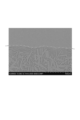
- FIG. 4 is a SEM image of the cross section of the ceramic plate in the example.
- FIG. 5 is a SEM image of a cross section of a ceramic plate in Comparative Example.
- each component in the composition means the total amount of the multiple substances present in the composition unless otherwise specified when there are multiple substances corresponding to each component in the composition. .
- One embodiment of the method for producing a ceramic plate includes firing a sheet having a molded plate containing boron nitride and a sintering aid, and a boron nitride-containing layer provided on at least part of the main surface of the molded plate. and a removing step of removing at least part of the release layer derived from the boron nitride-containing layer of the fired plate.
- FIG. 1 is a schematic diagram for explaining an example of a method for manufacturing a ceramic plate.
- FIG. 1(a) shows a step of preparing a sheet 10 having a molded plate 2 and boron nitride-containing layers 3 provided on both main surfaces of the molded plate 2 and firing it (firing step). be.
- FIG. 1(b) is a step (removal step) of removing at least part of the surface layers of both main surfaces of the fired plate 20 obtained by the firing step.
- the fired plate 20 includes a sintered body 4 (nitride sintered body) obtained by firing the molded plate 2, and the boron nitride-containing material provided on both main surfaces of the sintered body 4. and a release layer 5 obtained by firing the layer 3 .
- FIG. 1(a) shows a step of preparing a sheet 10 having a molded plate 2 and boron nitride-containing layers 3 provided on both main surfaces of the molded plate 2 and firing it (firing step). be.
- FIG. 1(c) shows a ceramic plate 100 obtained by removing the release layer 5 by the removal step described above.
- FIG. 1 shows an example in which the boron nitride-containing layer 3 is provided on both main surfaces of the molded plate 2, it may be formed on one main surface.
- FIG. 1 shows an example in which the release layer 5 is completely removed, it may be partially removed.
- the molded plate used in the firing process may be prepared by, for example, the following method. That is, it may be formed by forming a raw material powder containing boron nitride and a sintering aid into a plate shape.
- the raw material powder may further contain, for example, boron carbonitride, etc., in addition to the boron nitride and the sintering aid.
- the boron nitride may be amorphous boron nitride or hexagonal boron nitride.
- amorphous boron nitride powder having an average particle size of 0.5 to 10.0 ⁇ m or hexagonal boron nitride powder having an average particle size of 3.0 to 40.0 ⁇ m can be used.
- sintering aids include alkali metal carbonates such as lithium carbonate and sodium carbonate, calcium carbonate, and boric acid.
- a molded plate can be prepared by molding the raw material powder into a plate shape.
- the molding may be carried out by uniaxial pressing, cold isostatic pressing (CIP), or doctor blade.
- the molding method is not particularly limited, and press molding may be performed using a mold to form a molded plate.
- the molding pressure may be, for example, 5-350 MPa.
- the thickness of the shaped plate may be, for example, less than 2.0 mm.
- the content of the sintering aid may be adjusted.
- the lower limit of the content of the sintering aid is, for example, 12% by mass or more, 13% by mass or more, 14% by mass or more, 15% by mass or more, 16% by mass or more, or 17% by mass, based on the total amount of the molded plate. Above, 20% by mass or more, or 23% by mass or more.
- the content of the sintering aid is within the above range, when a plurality of molded plates are directly laminated, the sintered bodies after sintering may adhere to each other, but the present disclosure In the method for manufacturing a ceramic plate according to No. 1, since the release layer is provided, adhesion between the sintered bodies can be suppressed.
- the upper limit of the content of the sintering aid is, for example, 35% by mass or less, 32% by mass or less, 30% by mass or less, 27% by mass or less, or 25% by mass or less, based on the total amount of the molded plate. good.
- the density of the sintered body can be kept within an appropriate range, and high thermal conductivity can be ensured.
- the content of the sintering aid may be adjusted within the above range, and may be, for example, 12 to 35% by weight, 15 to 27% by weight, or 15 to 25% by weight, based on the total amount of the molded plate. .
- FIG. 1(a) shows an example in which the boron nitride-containing layer 3 is uniformly provided on both main surfaces of the molding plate 2, but it is formed only on one main surface. may have been Further, in the process described later, it is sufficient that the sintered bodies 4 can be separated from each other as the release layer 5, and the boron nitride-containing layer 3 is provided not on the entire surface of the main surface of the molding plate 2 but partially. may be Further, a boron nitride-containing layer 3 may be further provided on the side surface of the molded plate 2 .
- the boron nitride-containing layer 3 may be uniformly provided on at least one major surface of the molded plate 2 for ease of preparation of the sheet.
- the boron nitride-containing layer may be provided, for example, by preparing a slurry containing boron nitride and depositing the slurry on the main surface of the molding plate.
- the method of attaching the slurry to the molded plate is not particularly limited, and may be, for example, a method of coating the slurry or a method of immersing the molded plate in the slurry.
- the slurry can be prepared by dispersing boron nitride in a mixture of terpineol, a high-boiling organic solvent such as toluene, and an organic paste that functions as a binder for the BN powder.
- the organic sizing agent include cellulose-based sizing agents such as methyl cellulose and ethyl cellulose, and acrylic resins such as polyisobutyl methacrylate.
- the boron nitride for forming the slurry may be amorphous boron nitride or hexagonal boron nitride. From the point of view, it is desirable to contain amorphous boron nitride with low crystallinity and to consist only of amorphous boron nitride.
- the slurry preferably does not contain sintering aids.
- the sheet is fired to obtain a fired board.
- the lower limit of the firing temperature in the firing step may be, for example, 1600° C. or higher, 1650° C. or higher, 1700° C. or higher, or 1800° C. or higher.
- the upper limit of the firing temperature in the firing step may be, for example, 2200° C. or less, 2100° C. or less, or 2000° C. or less.
- the firing temperature may be adjusted within the ranges mentioned above, and may be, for example, 1600-2200°C, 1700-2100°C, or 1800-2100°C. Firing times may be, for example, 1-30 hours, 2-20 hours, 3-15 hours, or 4-10 hours.
- the firing process may be performed under an inert gas atmosphere such as nitrogen, helium, and argon.
- a batch type furnace or a continuous type furnace can be used.
- Batch type furnaces include, for example, muffle furnaces, tubular furnaces, atmosphere furnaces, and the like.
- continuous furnaces include rotary kilns, screw conveyor furnaces, tunnel furnaces, belt furnaces, pusher furnaces, and large continuous furnaces.
- a sintered board can be obtained.
- the removing step is a step of removing at least part of the release layer that constitutes the fired plate prepared as described above.
- FIG. 1(c) shows an example assuming that the release layer 5 is completely removed, but from the above point of view, the release layer 5 may be partially removed.
- the surface layer of the release layer 5 on the side opposite to the sintered body 4 side may be removed to reduce the height (reduce the thickness), and the release layer 5 is removed in a pattern. You may divide into a location and a location to maintain.
- the means for removing the release layer 5 in the removing step may be, for example, polishing.
- polishing for example, sandpaper, a grinder, and the like can be used.
- the removing step may be a step of polishing the fired plate from the release layer side.
- the removing step may be a step of polishing the fired plate 20 from the release layer 5 side by a thickness equal to or greater than the thickness of the boron nitride-containing layer 3 to reduce the height.
- the explanation is given on the assumption that one sheet is fired, but the above-described method for manufacturing the ceramic plate further includes a step of stacking a plurality of the sheets to obtain a laminate, and the firing step is the same as the above. It may be a step of sintering the laminate to obtain a plurality of the sintered plates.
- a plurality of molded plates forming a laminate are laminated with boron nitride-containing layers interposed therebetween.
- FIG. 2 is a perspective view showing an example of a ceramic plate.
- the ceramic plate 100 has a pair of main surfaces 100a and 100b, at least one of which is a polished surface.
- One embodiment of the ceramic plate is composed of a sintered body containing primary particles of boron nitride and has a polished surface. At least one principal surface of the ceramic plate may be a polished surface, but both principal surfaces are preferably polished surfaces.
- the main surface of the ceramic plate is preferably not a cut surface (for example, a cut surface with a wire saw).
- the ceramic plate can be manufactured, for example, by the method for manufacturing a ceramic plate described above.
- the polished surface is a surface having polishing marks, which are fine grooves formed by polishing.
- the maximum value of the groove depth of the groove group varies depending on the polishing conditions, it may be, for example, 20 ⁇ m or less, or 10 ⁇ m or less.
- the depth of the grooves can be determined by measurement with an optical microscope. In the case of adopting the polishing condition to obtain a polished surface with high smoothness, polishing marks can be confirmed with a microscope. Further, polishing may be performed until the polished surface becomes a mirror surface. Since a mirror surface cannot be obtained without polishing, the fact that the main surface of the ceramic plate is a mirror surface means that the main surface of the ceramic plate is a polished surface.
- a mirror surface in this specification means a surface having an arithmetic mean roughness Ra of 0.00 described in JIS B 0601: 1994 "Product Geometric Characteristic Specifications (GPS) - Surface Texture: Contour Method - Terms, Definitions and Surface Texture Parameters". It means less than 2 ⁇ m.
- the arithmetic mean roughness Ra can be measured by a line contact type measuring instrument.
- the line-contact type measuring instrument for example, Mitutoyo Corporation's "Surface Roughness Measuring Instrument Surftest SJ-301" (product name) can be used.
- the pore diameter of the ceramic plate may be adjusted from the viewpoint of maintaining the mechanical strength of the ceramic plate itself and improving the filling property of the resin.
- the lower limit of the median pore size of the ceramic plate may be, for example, 1.5 ⁇ m or more, 1.8 ⁇ m or more, or 2.0 ⁇ m or more.
- the upper limit of the median pore diameter of the ceramic plate may be, for example, 4.0 ⁇ m or less, 3.5 ⁇ m or less, or 3.0 ⁇ m or less.
- the upper limit of the median pore diameter is within the above range, it is possible to suppress deterioration of the mechanical strength of the ceramic plate and to make the ceramic plate excellent in handleability.
- the upper limit of the median pore diameter is within the above range, when a composite sheet with a resin is prepared, the contact area between the ceramic particles constituting the ceramic plate can be improved, and the thermal conductivity can be increased. can.
- the median pore size of the ceramic plate may be adjusted within the range described above, and may be, for example, 1.5-4.0 ⁇ m, 1.8-3.0 ⁇ m, or 2.0-3.0 ⁇ m.
- the median pore diameter of the ceramic plate can be measured by the following procedure. First, using a mercury porosimeter, the pore size distribution is obtained when the ceramic plate is pressurized while increasing the pressure from 0.0042 MPa to 206.8 MPa. Next, when the horizontal axis is the pore diameter and the vertical axis is the cumulative pore volume, the pore diameter when the cumulative pore volume reaches 50% of the total pore volume is the median pore diameter.
- the mercury porosimeter for example, "Autopore IV9500" (trade name) manufactured by Shimadzu Corporation can be used.
- the porosity of the ceramic plate that is, the ratio of the pore volume (V1) in the ceramic plate may be, for example, 30 to 65% by volume, or 40 to 60% by volume. If the porosity is too large, the strength of the ceramic plate tends to decrease. On the other hand, if the porosity is too small, the amount of resin that exudes when the composite sheet is adhered to the adherend tends to be small.
- the porosity of the ceramic plate is obtained by calculating the bulk density [B (kg/m 3 )] from the volume and mass of the ceramic plate, and calculating the bulk density and the theoretical density [A (kg/m 3 )] of the nitride. , can be obtained by the following formula (1).
- the theoretical density A of boron nitride is 2280 kg/m 3 .
- Porosity (% by volume) [1-(B/A)] x 100 (1)
- the thickness of the ceramic plate may be, for example, less than 2.0 mm, less than 1.8 mm, or less than 1.6 mm.
- a ceramic plate having such a thickness for example, it becomes easier to fill the pores of the ceramic plate with a resin, and a composite sheet having an excellent resin filling rate can be more easily prepared. can.
- the thickness of the ceramic plate may be, for example, 0.1 mm or more, or 0.2 mm or more.
- the thickness of the ceramic plate may be adjusted within the range described above, and may be, for example, 0.1 mm or more and less than 2.0 mm, or 0.2 mm or more and less than 1.6 mm.
- the thickness of the ceramic plate means a value measured along the direction perpendicular to the main surfaces 100a and 100b. If the thickness of the ceramic plate is not constant, the thickness is measured at 10 arbitrary locations, and the arithmetic mean value is taken as the thickness of the ceramic plate.
- the ceramic plate described above can be suitably used, for example, for manufacturing a composite sheet prepared by impregnating and semi-curing a resin composition.
- One embodiment of the composite sheet comprises a nitride sintered plate having pores and a resin filling the pores.
- the nitride sintered plate in the composite sheet is the ceramic plate described above.
- the resin includes, for example, a semi-cured product (B stage) of a resin composition containing a main agent and a curing agent.
- the semi-cured product is obtained by partially progressing the curing reaction of the resin composition.
- the semi-cured product can be further cured by a subsequent curing treatment.
- the resin may contain a cured product (C stage) of the resin composition.
- the resin composition may be a thermosetting resin composition.
- the semi-cured product may contain monomers such as a main agent and a curing agent in addition to the resin as a resin component. It can be confirmed by, for example, a differential scanning calorimeter that the resin contained in the composite sheet is a semi-cured product (B stage) before becoming a cured product (C stage).
- the lower limit of the curing rate of the resin contained in the composite sheet may be, for example, 10% or more, 15% or more, 20% or more, 25% or more, or 30% or more.
- the upper limit of the curing rate of the resin may be, for example, 55% or less, 50% or less, or 45% or less.
- the resin melts moderately during adhesion to the adherend, and the resin spreads over the adhesion interface, thereby exhibiting better adhesiveness.
- the curing rate of the resin contained in the composite sheet may be adjusted within the range described above, and may be, for example, 10-55%, 25-50%, or 30-50%.
- the resin filling rate may be adjusted from the viewpoint of further increasing the adhesiveness of the composite sheet, and may be, for example, 90% by volume or more, 92% by volume or more, 94% by volume or more, or 96% by volume or more.
- the upper limit of the resin filling rate is not particularly limited, but may be, for example, 100% by mass or less, or 98% by volume or less.
- the resin filling rate may be adjusted within the range described above, and may be, for example, 90 to 100% by volume, or 94 to 100% by volume.
- Resins include, for example, epoxy resins, silicone resins, cyanate resins, silicone rubbers, acrylic resins, phenolic resins, melamine resins, urea resins, bismaleimide resins, unsaturated polyesters, fluororesins, polyimides, polyamideimides, polyetherimides, poly Butylene terephthalate, polyethylene terephthalate, polyphenylene ether, polyphenylene sulfide, wholly aromatic polyester, polysulfone, liquid crystal polymer, polyethersulfone, polycarbonate, maleimide resin, maleimide-modified resin, ABS (acrylonitrile-butadiene-styrene) resin, AAS (acrylonitrile-acrylic rubber/styrene) resin, AES (acrylonitrile/ethylene/propylene/diene rubber-styrene) resin, polyglycolic acid resin, polyphthalamide, and polyacetal.
- epoxy resins silicone resins, cyanate resins,
- FIG. 3 is a cross-sectional view of an example of a laminated substrate cut in the thickness direction.
- Laminated substrate 300 includes composite sheet 200 , metal layer 30 adhered to main surface 200 a of composite sheet 200 , and metal layer 40 adhered to main surface 200 b of composite sheet 200 .
- the metal layers 30 and 40 are not particularly limited as long as they are made of metal.
- the metal layer may be, for example, a metal plate or a metal foil.
- the metal layers 30 and 40 may also have patterns such as circuits, for example.
- Materials for the metal layers 30 and 40 include, for example, aluminum and copper.
- the thickness of the metal layers 30, 40 may be, independently of each other, for example 0.035 mm or more or 10 mm or less. The material, thickness, presence/absence of patterns, etc. of the metal layers 30 and 40 may be the same or different.
- the laminated substrate 300 may have a resin layer between the composite sheet 200 and the metal layers 30 and 40 within the scope of the present disclosure.
- This resin layer may be formed by curing the resin exuded from the composite sheet 200 .
- the composite sheet 200 and the metal layers 30 and 40 in the laminated substrate 300 are sufficiently firmly adhered by the exuded resin, and thus have excellent adhesiveness. Since such a laminated substrate is thin and has excellent adhesion and heat dissipation properties, it can be suitably used as a heat dissipation member for semiconductor devices and the like.
- Example 1 100 parts by mass of orthoboric acid manufactured by Shin Nippon Denko Co., Ltd. and 35 parts by mass of acetylene black (trade name: HS100) manufactured by Denka Co., Ltd. were mixed using a Henschel mixer. The obtained mixture was filled in a graphite crucible and heated at 2200° C. for 5 hours in an argon atmosphere in an arc furnace to obtain massive boron carbide (B 4 C). The resulting mass was coarsely pulverized with a jaw crusher to obtain coarse powder. This coarse powder was further pulverized by a ball mill having silicon carbide balls ( ⁇ 10 mm) to obtain pulverized powder.
- HS100 acetylene black
- the prepared pulverized powder was filled in a crucible made of boron nitride. After that, using a resistance heating furnace, heating was performed for 10 hours under conditions of 2000° C. and 0.85 MPa in a nitrogen gas atmosphere. Thus, a fired product containing boron carbonitride (B 4 CN 4 ) and boron nitride (BN) was obtained.
- a sintering aid was prepared by blending powdered boric acid and calcium carbonate. In preparation, 50.0 parts by mass of calcium carbonate was blended with 100 parts by mass of boric acid. At this time, the atomic ratio of boron to calcium was 17.5 atomic % of calcium to 100 atomic % of boron. In this way, 20 parts by mass of the sintering aid was added to 100 parts by mass of the fired product, and mixed using a Henschel mixer to prepare powdery raw material powder.
- Three molded plates were prepared by the same operation. The content of sintering aid in each molded plate was 16.6% by weight.
- amorphous boron nitride manufactured by Denka Co., Ltd., trade name: GP
- a release agent slurry consisting of a mixture of 60 parts by weight of terpineol, 30 parts by weight of toluene, and 10 parts by weight of polyisobutyl methacrylate. Dispersed to prepare a slurry.
- the resulting slurry was used to form a coating film (boron nitride-containing layer) having a thickness of 0.03 mm on one main surface of the molded plate by a doctor blade method.
- the molded plates provided with the coating film were laminated with each other with the coating film interposed therebetween to obtain a laminate.
- the obtained laminate was placed in a boron nitride container and introduced into a batch-type high-frequency furnace. In a batch-type high-frequency furnace, it was heated for 5 hours under the conditions of atmospheric pressure, nitrogen flow rate of 5 L/min, and 2000° C. (firing step). After that, a laminate in which the boron nitride sintered plates (sintered bodies) and the release layers were alternately laminated was taken out from the boron nitride container. The boron nitride sintered plate constituting the laminate was peeled off using a thickness gauge leaf to obtain three fired plates with a release layer remaining on the surface layer. The thickness of the fired plate was 0.39 mm.
- Both main surfaces of the fired plate were polished with sandpaper by 0.05 mm from the surface layer to remove the release layer remaining on the surface layer (removal step).
- a ceramic plate which is a sintered body of boron nitride, was obtained.
- the thickness of the obtained ceramic plate was 0.29 mm.
- a cross-sectional SEM image of the ceramic plate is shown in FIG. As shown in FIG. 4, in the vicinity of the surface layer of the ceramic plate (the position indicated by the dotted line in FIG. 4), the primary particles of boron nitride that are oriented in a direction parallel to the main surface of the ceramic plate are removed. I was able to confirm that.
- groove groups were formed by polishing.
- the maximum depth of the grooves in the groove group was 10 ⁇ m.
- the polishing was performed so that the arithmetic mean roughness Ra was within the range of 1.0 to 2.0 ⁇ m.
- Example 1 A sintered plate was prepared in the same manner as in Example 1 before the polishing step. This sintered plate was used as a ceramic plate of Comparative Example 1. The thickness of the ceramic plate was 0.40 mm. A cross-sectional SEM image of the ceramic plate is shown in FIG. As shown in FIG. 5, in the vicinity of the surface layer of the ceramic plate (the position indicated by the dotted line in FIG. 5), it was confirmed that the primary particles of boron nitride were oriented in a direction parallel to the main surface of the ceramic plate.
- a resin composition having a curing rate of 13% was dropped onto the main surface of a ceramic plate heated to 160° C. while maintaining the temperature. Under atmospheric pressure, the resin composition dropped on the main surface of the ceramic plate is spread using a silicone rubber spatula, and while spreading the resin composition over the entire main surface, the pores of the ceramic plate are impregnated with the resin. A composition-impregnated body was obtained.
- the resin composition-impregnated body was heated at 160°C for 5 minutes under atmospheric pressure to semi-cure the resin composition.
- the curing rate of the resin composition contained in the semi-cured product was determined by measurement using a differential scanning calorimeter.
- the curing rate of the impregnated resin composition was 45%.
- the bulk density of the boron nitride sintered plate and composite sheet conforms to JIS Z 8807:2012 "Method for measuring density and specific gravity by geometric measurement", and the length of each side of the boron nitride sintered plate or composite sheet (measured with a vernier caliper) and the mass of the boron nitride sintered plate or composite sheet measured with an electronic balance (see JIS Z 8807:2012, item 9).
- the theoretical density of the composite sheet was determined by the following formula (4).
- Theoretical density of composite sheet bulk density of boron nitride sintered plate + true density of resin x (1 - bulk density of boron nitride sintered plate / true density of boron nitride) ... (4)
- the true density of the boron nitride sintered plate and resin is measured using a dry automatic densitometer in accordance with JIS Z 8807:2012 "Method for measuring density and specific gravity by gas replacement method". (See formulas (14) to (17) in item 11 of JIS Z 8807:2012).
- the present disclosure it is possible to provide a ceramic plate excellent in adhesiveness to adherends and capable of preparing a composite sheet with a resin, and a method for manufacturing the same. According to the present disclosure, it is also possible to provide a composite sheet having the ceramic plate described above and having excellent adhesion to an adherend.
Landscapes
- Chemical & Material Sciences (AREA)
- Engineering & Computer Science (AREA)
- Ceramic Engineering (AREA)
- Materials Engineering (AREA)
- Structural Engineering (AREA)
- Organic Chemistry (AREA)
- Manufacturing & Machinery (AREA)
- Microelectronics & Electronic Packaging (AREA)
- Cooling Or The Like Of Semiconductors Or Solid State Devices (AREA)
- Laminated Bodies (AREA)
Priority Applications (1)
| Application Number | Priority Date | Filing Date | Title |
|---|---|---|---|
| JP2023514411A JP7319482B2 (ja) | 2021-08-26 | 2022-08-24 | セラミックス板の製造方法、セラミックス板、複合シート、及び積層基板 |
Applications Claiming Priority (2)
| Application Number | Priority Date | Filing Date | Title |
|---|---|---|---|
| JP2021-138221 | 2021-08-26 | ||
| JP2021138221 | 2021-08-26 |
Publications (1)
| Publication Number | Publication Date |
|---|---|
| WO2023027122A1 true WO2023027122A1 (ja) | 2023-03-02 |
Family
ID=85322880
Family Applications (1)
| Application Number | Title | Priority Date | Filing Date |
|---|---|---|---|
| PCT/JP2022/031927 Ceased WO2023027122A1 (ja) | 2021-08-26 | 2022-08-24 | セラミックス板の製造方法、セラミックス板、複合シート、及び積層基板 |
Country Status (2)
| Country | Link |
|---|---|
| JP (1) | JP7319482B2 (https=) |
| WO (1) | WO2023027122A1 (https=) |
Citations (7)
| Publication number | Priority date | Publication date | Assignee | Title |
|---|---|---|---|---|
| JPS5433510A (en) * | 1977-07-01 | 1979-03-12 | Gen Electric | Cubic boronnnitride compressed body and method of making same |
| JPH02164775A (ja) * | 1988-12-19 | 1990-06-25 | Denki Kagaku Kogyo Kk | 立方晶窒化ほう素焼結体の製造方法 |
| JPH09278526A (ja) * | 1996-04-10 | 1997-10-28 | Denki Kagaku Kogyo Kk | セラミックス焼成用セッター |
| JP2002275571A (ja) * | 2001-03-13 | 2002-09-25 | Toshiba Tungaloy Co Ltd | cBN基焼結体およびその被覆工具 |
| JP2011178598A (ja) * | 2010-03-01 | 2011-09-15 | Hitachi Metals Ltd | 窒化珪素基板の製造方法および窒化珪素基板 |
| WO2013054852A1 (ja) * | 2011-10-11 | 2013-04-18 | 日立金属株式会社 | 窒化珪素基板および窒化珪素基板の製造方法 |
| WO2020203692A1 (ja) * | 2019-03-29 | 2020-10-08 | デンカ株式会社 | 複合体 |
Family Cites Families (1)
| Publication number | Priority date | Publication date | Assignee | Title |
|---|---|---|---|---|
| JP6256158B2 (ja) * | 2014-03-31 | 2018-01-10 | 三菱ケミカル株式会社 | 放熱シートおよび放熱シート製造方法、放熱シート用スラリー、並びにパワーデバイス装置 |
-
2022
- 2022-08-24 WO PCT/JP2022/031927 patent/WO2023027122A1/ja not_active Ceased
- 2022-08-24 JP JP2023514411A patent/JP7319482B2/ja active Active
Patent Citations (7)
| Publication number | Priority date | Publication date | Assignee | Title |
|---|---|---|---|---|
| JPS5433510A (en) * | 1977-07-01 | 1979-03-12 | Gen Electric | Cubic boronnnitride compressed body and method of making same |
| JPH02164775A (ja) * | 1988-12-19 | 1990-06-25 | Denki Kagaku Kogyo Kk | 立方晶窒化ほう素焼結体の製造方法 |
| JPH09278526A (ja) * | 1996-04-10 | 1997-10-28 | Denki Kagaku Kogyo Kk | セラミックス焼成用セッター |
| JP2002275571A (ja) * | 2001-03-13 | 2002-09-25 | Toshiba Tungaloy Co Ltd | cBN基焼結体およびその被覆工具 |
| JP2011178598A (ja) * | 2010-03-01 | 2011-09-15 | Hitachi Metals Ltd | 窒化珪素基板の製造方法および窒化珪素基板 |
| WO2013054852A1 (ja) * | 2011-10-11 | 2013-04-18 | 日立金属株式会社 | 窒化珪素基板および窒化珪素基板の製造方法 |
| WO2020203692A1 (ja) * | 2019-03-29 | 2020-10-08 | デンカ株式会社 | 複合体 |
Non-Patent Citations (1)
| Title |
|---|
| "Handbook of the latest technologies for smartphones and touch panel materials", 28 June 2013, TECHNICAL INFORMATION INSTITUTE, JP, ISBN: 978-4-86104-484-7, article NOBORU FUJIMOTO PLANNING AND EDITING: "Section 7 Boron Nitride Filler and Heat Dissipating Sheet", pages: 461 - 468, XP009543911 * |
Also Published As
| Publication number | Publication date |
|---|---|
| JPWO2023027122A1 (https=) | 2023-03-02 |
| JP7319482B2 (ja) | 2023-08-01 |
Similar Documents
| Publication | Publication Date | Title |
|---|---|---|
| JP4013386B2 (ja) | 半導体製造用保持体およびその製造方法 | |
| JPWO2017158993A1 (ja) | アルミニウム−ダイヤモンド系複合体及び放熱部品 | |
| WO2017065139A1 (ja) | アルミニウム-ダイヤモンド系複合体及びその製造方法 | |
| JP7566883B2 (ja) | 窒化ホウ素焼結体、複合体及びこれらの製造方法、並びに放熱部材 | |
| JP7550869B2 (ja) | 複合体及びその製造方法、並びに、積層体及びその製造方法 | |
| JP7217391B1 (ja) | 複合体及びその製造方法、並びに、積層体及びその製造方法 | |
| JP7319482B2 (ja) | セラミックス板の製造方法、セラミックス板、複合シート、及び積層基板 | |
| JP7598925B2 (ja) | 窒化ホウ素焼結体、複合体及びこれらの製造方法、並びに放熱部材 | |
| CN115515915A (zh) | 复合体及层叠体 | |
| JP7165844B2 (ja) | 複合シート及びその製造方法、並びに、積層体及びその製造方法 | |
| JP7196367B2 (ja) | 複合シート及びその製造方法、積層体及びその製造方法、並びに、パワーデバイス | |
| JP7374391B1 (ja) | 複合シート、及び積層体 | |
| JP7148758B1 (ja) | 複合シート及びその製造方法、並びに、積層体及びその製造方法 | |
| US20230271888A1 (en) | Composite and production method for composite | |
| JP2025100156A (ja) | 樹脂充填板の製造方法、及び、樹脂充填板 | |
| WO2021200967A1 (ja) | 複合体、及び放熱部材 | |
| CN116261782A (zh) | 复合片材及其制造方法、以及层叠体及其制造方法 | |
| WO2023054031A1 (ja) | 積層部品、及びその製造方法、並びに、積層体、及びその製造方法 | |
| CN115335348B (zh) | 氮化硼烧结体、复合体及它们的制造方法、以及散热构件 | |
| CN116034017A (zh) | 复合片材、层叠体及对复合片材的粘接性进行推定的评价方法 | |
| WO2021200719A1 (ja) | 窒化ホウ素焼結体、複合体及びこれらの製造方法、並びに放熱部材 | |
| WO2024048206A1 (ja) | 積層体、及び積層体の製造方法、並びに、積層基板、及び積層基板の製造方法 | |
| JP2024033151A (ja) | 複合基板の製造方法、及び、複合基板 | |
| CN116134005A (zh) | 对复合体的粘接可靠性及散热性能进行评价的方法以及复合体 | |
| WO2023027123A1 (ja) | 複合シート、及び複合シートの製造方法、並びに、積層基板 |
Legal Events
| Date | Code | Title | Description |
|---|---|---|---|
| ENP | Entry into the national phase |
Ref document number: 2023514411 Country of ref document: JP Kind code of ref document: A |
|
| 121 | Ep: the epo has been informed by wipo that ep was designated in this application |
Ref document number: 22861410 Country of ref document: EP Kind code of ref document: A1 |
|
| NENP | Non-entry into the national phase |
Ref country code: DE |
|
| 122 | Ep: pct application non-entry in european phase |
Ref document number: 22861410 Country of ref document: EP Kind code of ref document: A1 |