WO2023021922A1 - 抵抗スポット溶接継手およびその抵抗スポット溶接方法 - Google Patents
抵抗スポット溶接継手およびその抵抗スポット溶接方法 Download PDFInfo
- Publication number
- WO2023021922A1 WO2023021922A1 PCT/JP2022/028412 JP2022028412W WO2023021922A1 WO 2023021922 A1 WO2023021922 A1 WO 2023021922A1 JP 2022028412 W JP2022028412 W JP 2022028412W WO 2023021922 A1 WO2023021922 A1 WO 2023021922A1
- Authority
- WO
- WIPO (PCT)
- Prior art keywords
- nugget
- less
- resistance spot
- hardness
- spot welded
- Prior art date
- Legal status (The legal status is an assumption and is not a legal conclusion. Google has not performed a legal analysis and makes no representation as to the accuracy of the status listed.)
- Ceased
Links
Images


Classifications
-
- C—CHEMISTRY; METALLURGY
- C22—METALLURGY; FERROUS OR NON-FERROUS ALLOYS; TREATMENT OF ALLOYS OR NON-FERROUS METALS
- C22C—ALLOYS
- C22C38/00—Ferrous alloys, e.g. steel alloys
-
- B—PERFORMING OPERATIONS; TRANSPORTING
- B23—MACHINE TOOLS; METAL-WORKING NOT OTHERWISE PROVIDED FOR
- B23K—SOLDERING OR UNSOLDERING; WELDING; CLADDING OR PLATING BY SOLDERING OR WELDING; CUTTING BY APPLYING HEAT LOCALLY, e.g. FLAME CUTTING; WORKING BY LASER BEAM
- B23K11/00—Resistance welding; Severing by resistance heating
- B23K11/10—Spot welding; Stitch welding
- B23K11/11—Spot welding
- B23K11/115—Spot welding by means of two electrodes placed opposite one another on both sides of the welded parts
-
- B—PERFORMING OPERATIONS; TRANSPORTING
- B23—MACHINE TOOLS; METAL-WORKING NOT OTHERWISE PROVIDED FOR
- B23K—SOLDERING OR UNSOLDERING; WELDING; CLADDING OR PLATING BY SOLDERING OR WELDING; CUTTING BY APPLYING HEAT LOCALLY, e.g. FLAME CUTTING; WORKING BY LASER BEAM
- B23K11/00—Resistance welding; Severing by resistance heating
- B23K11/10—Spot welding; Stitch welding
- B23K11/11—Spot welding
-
- B—PERFORMING OPERATIONS; TRANSPORTING
- B23—MACHINE TOOLS; METAL-WORKING NOT OTHERWISE PROVIDED FOR
- B23K—SOLDERING OR UNSOLDERING; WELDING; CLADDING OR PLATING BY SOLDERING OR WELDING; CUTTING BY APPLYING HEAT LOCALLY, e.g. FLAME CUTTING; WORKING BY LASER BEAM
- B23K11/00—Resistance welding; Severing by resistance heating
- B23K11/16—Resistance welding; Severing by resistance heating taking account of the properties of the material to be welded
-
- B—PERFORMING OPERATIONS; TRANSPORTING
- B23—MACHINE TOOLS; METAL-WORKING NOT OTHERWISE PROVIDED FOR
- B23K—SOLDERING OR UNSOLDERING; WELDING; CLADDING OR PLATING BY SOLDERING OR WELDING; CUTTING BY APPLYING HEAT LOCALLY, e.g. FLAME CUTTING; WORKING BY LASER BEAM
- B23K11/00—Resistance welding; Severing by resistance heating
- B23K11/24—Electric supply or control circuits therefor
-
- C—CHEMISTRY; METALLURGY
- C22—METALLURGY; FERROUS OR NON-FERROUS ALLOYS; TREATMENT OF ALLOYS OR NON-FERROUS METALS
- C22C—ALLOYS
- C22C38/00—Ferrous alloys, e.g. steel alloys
- C22C38/001—Ferrous alloys, e.g. steel alloys containing N
-
- C—CHEMISTRY; METALLURGY
- C22—METALLURGY; FERROUS OR NON-FERROUS ALLOYS; TREATMENT OF ALLOYS OR NON-FERROUS METALS
- C22C—ALLOYS
- C22C38/00—Ferrous alloys, e.g. steel alloys
- C22C38/002—Ferrous alloys, e.g. steel alloys containing In, Mg, or other elements not provided for in one single group C22C38/001 - C22C38/60
-
- C—CHEMISTRY; METALLURGY
- C22—METALLURGY; FERROUS OR NON-FERROUS ALLOYS; TREATMENT OF ALLOYS OR NON-FERROUS METALS
- C22C—ALLOYS
- C22C38/00—Ferrous alloys, e.g. steel alloys
- C22C38/02—Ferrous alloys, e.g. steel alloys containing silicon
-
- C—CHEMISTRY; METALLURGY
- C22—METALLURGY; FERROUS OR NON-FERROUS ALLOYS; TREATMENT OF ALLOYS OR NON-FERROUS METALS
- C22C—ALLOYS
- C22C38/00—Ferrous alloys, e.g. steel alloys
- C22C38/04—Ferrous alloys, e.g. steel alloys containing manganese
-
- C—CHEMISTRY; METALLURGY
- C22—METALLURGY; FERROUS OR NON-FERROUS ALLOYS; TREATMENT OF ALLOYS OR NON-FERROUS METALS
- C22C—ALLOYS
- C22C38/00—Ferrous alloys, e.g. steel alloys
- C22C38/06—Ferrous alloys, e.g. steel alloys containing aluminium
-
- C—CHEMISTRY; METALLURGY
- C22—METALLURGY; FERROUS OR NON-FERROUS ALLOYS; TREATMENT OF ALLOYS OR NON-FERROUS METALS
- C22C—ALLOYS
- C22C38/00—Ferrous alloys, e.g. steel alloys
- C22C38/08—Ferrous alloys, e.g. steel alloys containing nickel
-
- C—CHEMISTRY; METALLURGY
- C22—METALLURGY; FERROUS OR NON-FERROUS ALLOYS; TREATMENT OF ALLOYS OR NON-FERROUS METALS
- C22C—ALLOYS
- C22C38/00—Ferrous alloys, e.g. steel alloys
- C22C38/12—Ferrous alloys, e.g. steel alloys containing tungsten, tantalum, molybdenum, vanadium, or niobium
-
- C—CHEMISTRY; METALLURGY
- C22—METALLURGY; FERROUS OR NON-FERROUS ALLOYS; TREATMENT OF ALLOYS OR NON-FERROUS METALS
- C22C—ALLOYS
- C22C38/00—Ferrous alloys, e.g. steel alloys
- C22C38/14—Ferrous alloys, e.g. steel alloys containing titanium or zirconium
-
- C—CHEMISTRY; METALLURGY
- C22—METALLURGY; FERROUS OR NON-FERROUS ALLOYS; TREATMENT OF ALLOYS OR NON-FERROUS METALS
- C22C—ALLOYS
- C22C38/00—Ferrous alloys, e.g. steel alloys
- C22C38/16—Ferrous alloys, e.g. steel alloys containing copper
-
- C—CHEMISTRY; METALLURGY
- C22—METALLURGY; FERROUS OR NON-FERROUS ALLOYS; TREATMENT OF ALLOYS OR NON-FERROUS METALS
- C22C—ALLOYS
- C22C38/00—Ferrous alloys, e.g. steel alloys
- C22C38/18—Ferrous alloys, e.g. steel alloys containing chromium
- C22C38/40—Ferrous alloys, e.g. steel alloys containing chromium with nickel
- C22C38/58—Ferrous alloys, e.g. steel alloys containing chromium with nickel with more than 1.5% by weight of manganese
Definitions
- the present invention relates to a resistance spot welded joint and its resistance spot welding method.
- the joint strength of resistance spot welds joined by resistance spot welding is divided into the tensile strength in the shear direction (TSS) and the tensile strength in the peeling direction (CTS). tension strength).
- TSS in resistance spot welds tends to increase with the tensile strength of the base metal
- CTS is said to decrease when the tensile strength of the base metal is 780 MPa or more.
- the failure morphology of the resistance spot weld (weld) changes from ductile plug failure in the base metal or heat affected zone (HAZ) around the resistance spot weld to brittleness in the nugget. transition to interfacial rupture or partial plug rupture.
- the cause of the decrease in CTS is, for example, brittle fracture caused by hardening of the nugget edge after quenching. Therefore, in order to solve such problems, various post-energization methods have been studied in which current is again supplied after the main current has been supplied.
- Patent Documents 1 to 3 US Pat. No. 5,400,003 defines a weld where the nugget ends are tempered. Specifically, in the nugget outer layer region, the microstructure consists of a dendrite structure with an average arm spacing of 12 ⁇ m or less, and the average grain size of carbides contained in the microstructure is 5 nm to 100 nm. It discloses that the number density of carbides is 2 ⁇ 10 6 pieces/mm 2 or more.
- the melt-solidified zone (nugget) and the heat-affected zone in the joint where the resistance-welded steel plate having a specific chemical composition is resistance-welded have a structure in which tempered martensite or tempered bainite is the main phase. is disclosed.
- Patent Document 3 discloses a resistance spot welded joint that defines the hardness of the outside of the nugget and the structure inside the nugget.
- the resistance spot welded part of this resistance spot welded joint is provided that the structure in the nugget is an equiaxed martensite structure and that a softened region having a lower hardness than the base material exists outside the nugget.
- Japanese Patent No. 5043236 Japanese Patent No. 5182855 Japanese Patent No. 5895430
- Patent Document 1 specifies that the microstructure of the nugget outer layer region is composed of a dendrite structure with an average arm spacing of 12 ⁇ m or less. However, this average arm spacing is not an indicator of the degree of tempering.
- Patent Document 1 specifies that the average grain size of carbides contained in the microstructure is 5 nm to 100 nm, but since the average grain size of these carbides is small, the degree of tempering is small.
- the hardness of the nugget edge is reduced the most to avoid stress concentration on the nugget edge, and the nugget edge is locally tempered to improve the toughness of the nugget edge. I am letting That is, in the present invention, local strong tempering is applied to the nugget edge, and it is clear that the degree of tempering is different from that in Patent Document 1 also from the average grain size of the carbide as described later. be.
- Patent Document 2 When the technique of Patent Document 2 is applied to welding using a steel plate (high-strength steel plate) having the chemical composition of the present invention described later, after the nugget is generated, the martensite structure at the end of the nugget is tempered martensite. A tempering process is required. That is, the present invention and Patent Document 2 have different technical ideas.
- Patent Document 3 only defines the hardness of the outside of the nugget and the structure inside the nugget, and does not give any consideration to controlling the hardness inside the nugget.
- the present invention has been made in view of the above problems, and has a resistance spot welded joint in which a plurality of steel plates including at least one high-strength steel plate are resistance spot welded to improve joint strength. and its object is to provide a resistance spot welding method.
- the present invention uses a plate assembly containing at least one high-strength steel plate, a cross tensile strength (CTS) reduction mechanism in resistance spot welding, and a method for improving cross tensile strength (CTS). have been diligently examined.
- CTS cross tensile strength
- the CTS decreases as the strength of the steel sheet increases.
- the fracture morphology for low CTS ranges from ductile plug rupture in the base metal or heat affected zone (HAZ) around the resistance spot weld to interfacial or partial plug rupture in the nugget to brittle, Transition. This makes it difficult to ensure CTS with high-strength steel sheets.
- the causes of interface breakage are (a) embrittlement of the nugget edge due to the formation of a hardened structure due to rapid cooling after nugget formation, (b) stress concentration at the nugget edge due to hardening, and (c) nugget The nugget edge cracks due to the low toughness of the edge. In order to prevent this brittle fracture, it is necessary that the structure of the nugget edge has sufficient toughness and that the stress concentration on the nugget edge is alleviated.
- the hardness (Vickers hardness) in a predetermined region of the nugget end (region indicated by "L” in FIG. It softens most compared to the hardness in the region of the nugget interior and heat affected zone, excluding certain regions of the nugget edge. This improves the toughness of the nugget edge.
- the term "heat-affected zone” refers to a region in which hardness continuously changes compared to the hardness of the base material.
- the nugget edge has sufficient toughness, stress concentration on the nugget edge is alleviated when cracks enter the nugget edge from the HAZ. Therefore, even if a crack penetrates into the HAZ or the edge of the nugget, the crack hardly penetrates into the nugget because of the high toughness of the edge of the nugget. As a result, it has become possible to set the rupture mode to plug rupture or partial plug rupture slightly inside the nugget. In addition, it was clarified that the strength of the CTS is improved by leaving the plug.
- the high-strength steel plate is mass%, C: 0.05 to 0.6%, Si: 0.1 to 2.0%, Mn: 1.5 to 4.0%, and P: 0.10% or less, with the balance containing Fe and unavoidable impurities,
- the two points on the boundary of the nugget that intersect the overlapping surface of the steel plate are defined as the first end and the second end, and the length of the line segment X connecting the first end and the second end is D (mm) and the positions on the line segment X toward the center of the nugget from the first end and the second end are points a and b,
- Each distance L (mm) from the first end to the point a and from the second end to the point b has the relationship of formula (1) with respect to the length D (mm) of the line segment X
- a method of resistance spot welding a resistance spot welded joint comprising: 800 ⁇ tc (2) 1.1 ⁇ I m ⁇ I t ⁇ 2.0 ⁇ I m (3) 100 ⁇ t t ⁇ 200 (4) I tm ⁇ I t (5) 300 ⁇ ttm ⁇ 3500 (6)
- the present invention it is possible to improve the toughness of the nugget edge in the resistance spot welded portion of a resistance spot welded joint in which a plurality of steel plates including high-strength steel plates are welded. As a result, the joint strength of the resistance spot-welded joint can be improved, thereby producing a significant industrial effect.
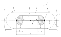
- FIG. 1 is a cross-sectional view schematically showing the periphery of a resistance spot welded portion of a resistance spot welded joint according to one embodiment of the present invention.
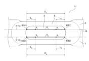
- FIG. 2 is a cross-sectional view schematically showing the periphery of a resistance spot welded portion of a resistance spot welded joint according to one embodiment of the present invention.
- FIG. 3 is a cross-sectional view schematically showing the periphery of a resistance spot welded portion of a resistance spot welded joint according to one embodiment of the present invention.
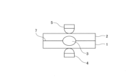
- FIG. 4 is a cross-sectional view illustrating an example of the resistance spot welding method of the present invention.
- FIG. 5 is a schematic diagram for explaining the method of measuring the hardness of the nugget edge in the present invention.
- FIG. 5 is a schematic diagram for explaining the method of measuring the hardness of the nugget edge in the present invention.
- FIG. 6 is a schematic diagram illustrating a method for measuring the average number density of carbides at the edge of a nugget in the present invention.
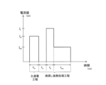
- FIG. 7 is a diagram illustrating an example of an energization pattern of the resistance spot welding method of the present invention.
- FIGS. 1-3 show, as an example, cross-sectional views in the plate thickness direction of a resistance spot welded portion and its surroundings in a resistance spot welded joint of the present invention.
- FIG. 1 shows the case where the number of steel plates to be overlapped is two
- FIG. 2 shows the case where the number of steel plates to be overlapped is two and there is a gap between the steel plates
- the present invention is a resistance spot welded joint having a resistance spot welded portion in which a plurality of superimposed steel plates are resistance spot welded.
- the steel sheets to be superimposed include at least one high-strength steel sheet to be described later.
- the number of steel plates mentioned above is not particularly limited, and may be two or more. Although the upper limit of the number of steel sheets described above is not particularly specified, it is preferable to set the number to four or less.
- FIG. 1 shows a resistance spot-welded joint 11 in which two steel plates are superimposed and welded, and a high-strength steel plate is used for the steel plate 1 placed on the lower side and/or the steel plate 2 placed on the upper side.
- a high-strength steel plate is used for the steel plate 2 on the upper side.
- the high-strength steel sheet may have a plating layer as described later, the illustration of the plating layer on the surface of the steel sheet is omitted in FIG.
- the steel sheet mating surfaces (lapped surfaces) 7 of the steel sheets 1 and 2 are formed with resistance spot welds, which will be described below.
- the resistance spot weld (hereinafter referred to as the “weld”) of the resistance spot weld joint 11 includes a nugget 3 and a heat affected zone (HAZ) 6 formed to surround the nugget 3. and
- the nugget 3 is a fusion zone that is formed in a circular (elliptical) shape when the welded zone is viewed from the steel plate surface side.
- the structure and properties in the region of the edge of the nugget 3 are defined as follows. 1 to 3 show cross sections in the plate thickness direction passing through the center of the nugget 3 when the welded portion is viewed from the steel plate surface side.
- two points on the boundary of the nugget 3 that intersect with the overlapping surfaces 7 of the steel plates 1 and 2 are defined as a first end 8 and a second end 9 .
- D (mm) be the length of a line segment X connecting the first end portion 8 and the second end portion 9 .
- the positions on the line segment X toward the center of the nugget 3 are points a and b, and the point a from the first end 8 and the point a from the second end 9
- each distance to b be L (mm).
- the region in the nugget 3 (the hatched region in FIG.
- the hardness (Vickers hardness) of the nugget's most softened region 31 in at least one lap surface 7 is 90% or less of the hardness of the HAZ 6, and the structure of the nugget's most softened region 31 is tempered martensite. and the average number density of carbides having a grain size of 100 nm or more in the nugget's most softened region 31 is 10 or more per 5 ⁇ m 2 of plate cross section.
- the hardness of the nugget most softened region 31 is the lowest softened region even when compared with the hardness of the region in the nugget 3 excluding the nugget most softened region 31 .
- the nugget's most softened region 31 exists on each of the stacked surfaces 71 and 72.
- the nugget 3 located in the middle of the gap and intersecting the straight line Y parallel to the overlapping surface 7 are defined as a first end 8 and a second end 9 .
- the nugget softened region (not shown) on the overlapping surface 71 and/or the nugget softening region (not shown) on the overlapping surface 72 have the following structure and properties: The effects of the present invention can be obtained.
- the "hardness of the nugget's most softened region 31" refers to the Vickers hardness of the nugget's most softened region 31 measured according to JISZ2244 (2020). Specifically, according to the measurement method described in the examples below, at a position 0.2 mm above the overlapping surface 7 of the steel plate in the plate thickness direction, and on a straight line parallel to the overlapping surface 7 (Fig. 5 ) are measured at intervals of 0.2 mm. The measurement area is from the nugget center to the outer edge of HAZ6. The lowest hardness value (most softened value) within this measurement area and within the area of the nugget's most softened area 31 is defined as "the hardness of the nugget's most softened area 31" (see FIG. 5).
- the above “hardness of HAZ6” refers to the average value of Vickers hardness measured in accordance with JISZ2244 (2020) in the region within HAZ6. Specifically, according to the measurement method described in the examples below, at a position 0.2 mm above the overlapping surface 7 of the steel plate in the plate thickness direction, and on a straight line parallel to the overlapping surface 7 (Fig. 5 ) are measured at intervals of 0.2 mm. The measurement area is from the nugget center to the outer edge of HAZ6. In this measurement area, the average value of the hardness in the range from the boundary between the HAZ 6 and the nugget 3 to the outer edge of the HAZ 6 is defined as "HAZ 6 hardness" (see FIG. 5).
- the above-mentioned "hardness of the region in the nugget 3 excluding the nugget most softened region 31" is the nugget Refers to the hardness within 3.
- This hardness can also be measured according to JISZ2244 (2020), similar to the method described above. Specifically, at a position 0.2 mm above the overlapping surface 7 of the steel plate in the plate thickness direction and on a straight line parallel to the overlapping surface 7 (on the straight line Y shown in FIG. 5), 0.2 mm Measured at intervals of The measurement area is from the nugget center to the outer edge of HAZ6.
- the hardness of this nugget most softened region 31 is set to 90% or less of the hardness of the HAZ6. It is preferably 87% or less, more preferably 85% or less, still more preferably 80% or less.
- the lower limit of the hardness of the nugget most softened region 31 is not particularly defined. The nugget's most softened region 31 is tempered the most, and even when the structure of this region 31 is entirely tempered martensite, the target hardness can be obtained.
- the hardness of the nugget most softened region 31 is preferably 55% or more, more preferably 60% or more, and still more preferably 70% or more of the hardness of the HAZ6.
- the hardness of the nugget's most softened region 31 is the lowest softened region even compared to the hardness of the regions within the nugget 3 excluding the nugget's most softened region 31 .
- the toughness of the nugget edge is improved, and the crack propagates through the nugget edge during CTS loading.
- the CTS is improved by causing plug breakage or partial plug breakage of 70% or more of the plug portion.
- the hardness of the nugget's most softened region 31 is preferably 55% or more, more preferably 60% or more, relative to the hardness of the region in the nugget 3 excluding the nugget's most softened region 31. % or more, and even more preferably 75% or more.
- the hardness ratio is preferably 90% or less, more preferably 85% or less.
- the hardness of the nugget's most softened region 31, nugget 3, and HAZ 6 can be measured by the method described in Examples below. The example shown in FIG.
- the measurement is performed at a position 0.2 mm above the overlapping surface of the steel plates. That is, for example, when a high-strength steel plate is used for the steel plate 1 on the lower side, the measurement is performed at "a position 0.2 mm below the overlapping surface".
- the tempered martensite of the nugget softest region 31 should be 50% or more in terms of area ratio with respect to the entire nugget softest region 31 . More preferably, the area ratio is 55% or more, more preferably 60% or more, and even more preferably 65% or more.
- the upper limit of tempered martensite in the nugget's most softened region 31 is not particularly defined. This is because, as described above, even when the structure of the nugget's most softened region 31 is composed of tempered martensite with an area ratio of 100%, the effect of improving toughness and alleviating stress concentration at the nugget edge can be expected.
- the area ratio of tempered martensite in the nugget's most softened region 31 is preferably 100% or less, more preferably 98% or less, and still more preferably 95% or less.
- the residual structure other than the tempered martensite in the nugget's most softened region 31 becomes martensite and/or ferrite.
- the area ratio of a structure other than tempered martensite is large, it becomes difficult to achieve the effect of improving the toughness of the nugget edge and alleviating stress concentration.
- the total area ratio of the remaining structures is preferably 50% or less, more preferably 45% or less, even more preferably 40% or less, and 30% or less. is even more preferred.
- the structure of the nugget's most softened region 31 can be measured by the method described in Examples below.
- the average number density of carbides having a grain size of 100 nm or more in the nugget's most softened region 31 is 10 or more per 5 ⁇ m 2 of plate cross section.
- the grain size of the carbide is set to 100 nm or more is to confirm that coarse carbide is generated as a result of sufficient progress of tempering.
- the particle size of the carbide is preferably 500 nm or less.
- the average number density is set to 10 or more per 5 ⁇ m 2 of plate cross section.
- the average number density is more preferably 15 or more per 5 ⁇ m 2 of plate cross section, more preferably 30 or more per 5 ⁇ m 2 of plate cross section, still more preferably 50 or more per 5 ⁇ m 2 of plate cross section. Note that the upper limit of the average number density is not particularly defined.
- the average number density is preferably 450 or less per 5 ⁇ m 2 of the plate cross section, more preferably 400 or less per 5 ⁇ m 2 of the plate cross section, and more preferably 400 or less per 5 ⁇ m 2 of the plate cross section. More preferably 250 or less, and even more preferably 150 or less per 5 ⁇ m 2 of plate cross section.
- the nugget's most softened region 31 is subdivided into a grid, and observation is started from the position indicated by "1" in FIG. Observation is continued while moving the observation position until satisfies the above average number density.
- the above effects can be obtained.
- the particle size of carbides and the average number density of carbides can be measured by the methods described in Examples described later.
- C 0.05-0.6% C is an element that contributes to strengthening of steel. If the C content is less than 0.05%, the strength of the steel becomes low, and it is extremely difficult to produce a steel sheet with a tensile strength of 780 MPa or more. On the other hand, when the C content exceeds 0.6%, although the strength of the steel sheet increases, the amount of hard martensite becomes excessive and microvoids increase. Furthermore, the nugget and its surrounding HAZ are excessively hardened and embrittled, making it difficult to improve the CTS. Therefore, the C content should be 0.05 to 0.6%. The C content is more preferably 0.10% or more. The C content is more preferably 0.50% or less, still more preferably 0.45% or less.
- Si 0.1-2.0%
- Si content 0.1% or more, it effectively acts to strengthen the steel.
- Si since Si is a ferrite former element, it works predominantly for the generation of ferrite at the nugget edge.
- the Si content should be 0.1 to 2.0%.
- the Si content is more preferably 0.2% or more and more preferably 1.8% or less.
- Mn 1.5-4.0%
- the Mn content is less than 1.5%, a high joint strength can be obtained without long-term cooling as in the present invention.
- the Mn content should be 1.5 to 4.0%.
- the Mn content is more preferably 2.0% or more.
- the Mn content is more preferably 3.7% or less, still more preferably 3.5% or less, even more preferably 3.2% or less, and even more preferably 2.9% or less. .
- P 0.10% or less
- P is an unavoidable impurity, but if the P content exceeds 0.10%, strong segregation appears at the nugget edge of the weld, making it difficult to improve joint strength. Therefore, the P content is set to 0.10% or less.
- the P content is preferably 0.05% or less, more preferably 0.02% or less.
- the lower limit of the P content is not particularly limited. However, excessive reduction causes an increase in cost, so the P content is preferably 0.005% or more.
- the high-strength steel sheet used in the present invention contains each of the above elements, and the balance is Fe and unavoidable impurities.
- the above composition is the basic composition of the high-strength steel sheet.
- one or more elements selected from Al, B, Ca, Cr, Cu, Ni, Mo, Ti, V, and Nb may be added as necessary.
- the following components of Al, B, Ca, Cr, Cu, Ni, Mo, Ti, V, and Nb can be contained as necessary, so these components may be 0%.
- Al 2.0% or less
- Al is an element capable of controlling the structure for refining austenite grains, but if added in a large amount, the toughness deteriorates. Therefore, when Al is contained, the Al content is preferably 2.0% or less.
- the Al content is more preferably 0.10% or less, still more preferably 0.08% or less, and even more preferably 0.07% or less.
- the Al content is more preferably 0.005% or more, more preferably 0.010% or more.
- B 0.005% or less
- B is an element that can improve hardenability and strengthen steel. Therefore, when B is contained, the B content is preferably 0.0005% or more. More preferably, it is 0.0007% or more. However, even if a large amount of B is added, the above effect saturates.
- the B content is more preferably 0.0010% or less.
- Ca 0.005% or less Ca is an element that can contribute to improving the workability of steel. However, if a large amount of Ca is added, the toughness deteriorates. Therefore, when Ca is contained, the Ca content is set to 0.005% or less. The Ca content is more preferably 0.004% or less. The Ca content is preferably 0.001% or more.
- Cr 1.0% or less Cr is an element that can improve strength by improving hardenability. However, if the Cr content exceeds 1.0% and is excessive, the toughness of the HAZ may deteriorate. Therefore, when Cr is contained, the Cr content is set to 1.0% or less. The Cr content is more preferably 0.8% or less. The Cr content is preferably 0.01% or more.
- Cu, Ni, and Mo are elements that can contribute to improving the strength of steel. However, Cu, Ni, and Mo degrade toughness when added in large amounts. Therefore, when these elements are contained, the Cu content is 0.8% or less, the Ni content is 1.0% or less, and the Mo content is 1.0% or less.
- the Cu content is more preferably 0.6% or less.
- the Cu content is preferably 0.005% or more, more preferably 0.006% or more.
- the Ni content is more preferably 0.8% or less.
- the Ni content is preferably 0.01% or more.
- Mo content is more preferably 0.8% or less.
- the Mo content is preferably 0.005% or more, more preferably 0.006% or more.
- Ti 0.20% or less
- Ti is an element that can improve hardenability and strengthen steel. However, when Ti is added in a large amount, it forms carbides, and its precipitation hardening significantly deteriorates the toughness. Therefore, when Ti is contained, the Ti content should be 0.20% or less. The Ti content is more preferably 0.15% or less. The Ti content is preferably 0.003% or more, more preferably 0.004% or more.
- V 0.50% or less
- V is an element capable of strengthening the steel by controlling the structure through precipitation hardening.
- the V content is preferably 0.50% or less.
- the V content is more preferably 0.3% or less.
- the V content is preferably 0.005% or more, more preferably 0.02% or more.
- Nb 0.080% or less Nb improves cross tensile strength and delayed fracture resistance after resistance welding by forming fine carbonitrides. In order to obtain the effect, it is necessary to contain 0.005% or more of Nb. On the other hand, when a large amount of Nb is added, not only does the elongation remarkably decrease, but also the toughness remarkably deteriorates. For this reason, when Nb is contained, the Nb content is made 0.080% or less. The Nb content is more preferably 0.070% or less, still more preferably 0.060% or less. The Nb content is preferably 0.005% or more, more preferably 0.006% or more.
- S 0.005% or less
- S is an element that segregates at grain boundaries and embrittles steel. S is an element that is inevitably included. Furthermore, S reduces the local deformability of sulfides and steel sheets. Therefore, the S content is preferably 0.005% or less.
- the S content is more preferably 0.004% or less, more preferably 0.003% or less.
- the lower limit of the S content is not particularly limited. However, excessive reduction causes an increase in cost, so the S content is preferably 0.001% or more.
- N 0.010% or less
- N is an element that deteriorates the aging resistance of steel.
- N is an element that is inevitably included. Therefore, when N is contained, the N content is preferably 0.010% or less.
- the N content is more preferably 0.008% or less.
- the N content is preferably 0.001% or more.
- O oxygen
- oxygen is an element that deteriorates the cleanliness and toughness of steel by forming nonmetallic inclusions. Therefore, when O is contained, the O content is preferably 0.03% or less. More preferably, the O content is 0.02% or less. Also, the O content is preferably 0.005% or more.
- the high-strength steel sheet having the chemical composition described above preferably has a tensile strength of 780 MPa or more.
- the tensile strength of the high-strength steel sheet is more preferably 1180 MPa or more.
- the CTS may decrease.
- the hardness of the nugget edge is set to the softest hardness in the weld zone, so that the vicinity of the nugget edge has toughness. becomes. As a result, brittle breakage of the nugget end can be prevented. Thereby, the welded part can suppress the decrease in CTS. It should be noted that even a high-strength steel sheet having a tensile strength of less than 780 MPa naturally obtains the above effects.
- the high-strength steel sheet of the present invention can obtain the above effects even if it is a steel sheet (galvanized steel sheet) having a galvanized layer on the steel sheet surface after being subjected to galvanizing treatment.
- a zinc plating layer refers to a plating layer containing zinc as a main component.
- the plating layer containing zinc as a main component includes, for example, a hot-dip galvanizing layer, an electrogalvanizing layer, a Zn--Al plating layer, a Zn--Ni layer, and the like.
- the high-strength steel sheet of the present invention may be an alloyed galvanized steel sheet having an alloyed galvanized layer on the surface of the base material by performing an alloying treatment after performing the above-described galvanizing treatment.
- the steel sheets to be superimposed in the present invention may be a plurality of steel sheets of the same type, or a plurality of steel sheets of different types.
- a steel sheet having a galvanized layer on its surface galvanized steel sheet
- a steel sheet having no galvanized layer on its surface cold-rolled steel sheet
- the thickness of the steel sheet is preferably 0.4 mm to 2.2 mm, for example.
- Resistance spot welding method Next, one embodiment of the resistance spot welding method for manufacturing the resistance spot welded joint of the present invention having the welded portion described above will be described.
- a plate assembly For example, as shown in Fig. 4, two steel plates 1 and 2 are superimposed to form a plate assembly. Then, the pair of welding electrodes 4 and 5 arranged on the lower side and the upper side of the plate set sandwich the plate set, and while applying pressure, the welding conditions are controlled to a predetermined value, and current is applied. As a result, the above-described welded portion can be formed by joining the plates that form the overlapping surfaces 7 of the steel plates (see FIG. 1).
- the main energizing process and the post-tempering heat treatment process are included as the process of energizing the steel sheets 1 and 2 that are sandwiched between the welding electrodes 4 and 5.
- Each step of the present invention will be described in detail below.
- FIG. 7 shows an example of the energization pattern of the present invention.
- the main energization process is performed, and then the post-tempering heat treatment process is performed in which the cooling process, the temperature rising process and the holding process are performed in this order.
- the main energizing step is a step of melting the overlapping surfaces 7 of the steel plates 1 and 2 to form a nugget 3 of a required size (see FIG. 4).
- a nugget is formed by energizing at a current value I m (kA).
- the nugget diameter (mm) used for resistance spot welding (welding) of automotive steel plates is generally 3.0 ⁇ t to 6.0 ⁇ t (t (mm) is the plate thickness). In the present invention, this numerical range is defined as the "target nugget diameter".
- the energizing conditions and pressurizing conditions for forming the nugget 3 are not particularly limited as long as the nugget 3 having the target nugget diameter is obtained.
- the "t” in the above “having a thickness of t (mm)” refers to the thickness of the steel sheet having the smallest thickness among the steel sheets used in the assembly.
- the energizing conditions and pressurizing conditions in the main energizing process are as follows. is preferably controlled to
- the current value I m (kA) in the main energizing step is preferably 3.0 kA to 8.0 kA. If the current value Im is too small, the target nugget diameter cannot be stably obtained. On the other hand, if the current value I m is too large, the nugget diameter may become too large, or the degree of melting of the steel plate may increase, and the melted welds may protrude from the gap between the plates, resulting in a smaller nugget diameter. may become. For this reason, the current value I m is set to 3.0 kA to 8.0 kA.
- the current value Im is more preferably 3.5 kA or more, more preferably 4.0 kA or more.
- the current value I m is more preferably 7.5 kA or less, more preferably 7.0 kA or less.
- the energization time t m (ms) of the main energization step is preferably 120 ms to 400 ms. This is the time for stably forming the nugget 3 having the target nugget diameter, similarly to the current value Im . If the energization time t m is less than 120 ms, there is a concern that nuggets are less likely to form. On the other hand, when the energization time t m exceeds 400 ms, there are concerns that the nugget diameter to be formed may become larger than the target nugget diameter, and workability may be reduced.
- the energization time t m is preferably 200 ms or longer. The energization time is preferably 350 ms or less. However, if the required nugget diameter is obtained, the energization time t m can be set shorter or longer than the above numerical range.
- the pressurizing force is preferably 2.0 kN to 7.0 kN. If the applied pressure is too large, the energized diameter will expand, making it difficult to secure the nugget diameter. On the other hand, if the applied pressure is too small, the energization diameter becomes small, and expulsion tends to occur. For this reason, the pressure is set to 2.0 kN to 7.0 kN.
- the applied pressure is more preferably 3.0 kN or more, and more preferably 6.5 kN or less.
- the applied force may be limited by the equipment capabilities used. The pressure can be set low or high relative to the above numerical range as long as the pressure is such that the required nugget diameter can be obtained.
- the post-tempering heat treatment step is a post-heat treatment step for tempering the nugget end portion of the nugget 3 formed in the main current-applying step to improve toughness.
- the nugget edge structure is tempered martensite by tempering, and the nugget edge (that is, the nugget most softened region 31) is effectively tempered so that the hardness becomes the most softened portion. is.
- the weld zone is subjected to a cooling process, a heating process and a holding process in this order.
- the cooling time t c (ms) is set to 800 ms or longer.
- the cooling time tc is preferably 850 ms or longer, more preferably 900 ms or longer, and still more preferably 1000 ms or longer.
- the upper limit of the cooling time t c (ms) in the cooling process is not particularly limited. Since the steel sheet targeted by the present invention is a steel sheet for automobiles, a long welding time results in a decrease in welding efficiency. Therefore, the cooling time t c (ms) is preferably 2200 (ms) or less, more preferably 2000 (ms) or less.
- the cooling process is followed by the heating process.
- energization post-energization
- appropriate temperature range refers to a tempering temperature range in which the hardness of the nugget end portion (specifically, the nugget's most softened region 31 shown in FIG. 1, etc.) becomes the most softened portion.
- the welding portion is energized at the current value I t (kA) shown in Equation (3) for the energization time t t (ms) shown in Equation (4).
- I t (kA) shown in Equation (3)
- t t (ms) shown in Equation (4).
- 100 ⁇ t t ⁇ 200 (4) Normally, even if the current value of the energization (post-energization) after the main energization step is set constant and the energization is performed, the temperature of the nugget end rises as the energization time of the post-energization increases. Therefore, tempering in the target temperature range is temporary.
- the temperature of the nugget end is shortened to the above-mentioned appropriate temperature, that is, the temperature of Ac 1 point or more.
- a rapid temperature rise in time is of particular importance.
- the structure of the nugget end portion becomes tempered martensite, and can be effectively tempered. If the current value I t in this process is too low, the effect of tempering is reduced. On the other hand, if the current value I t in this process is too high, it will exceed the Ac 3 point, and the structure of the nugget end portion cannot be tempered martensite.
- the current value I t (kA) in the temperature rising process satisfies the relationship of 1.1 ⁇ I m ⁇ I t ⁇ 2.0 ⁇ I m .
- the current value I t is preferably (1.12 ⁇ I m )(kA) or more, more preferably (1.14 ⁇ I m )(kA) or more.
- the current value I t in the temperature rising process exceeds (2.0 ⁇ I m ) (kA)
- the current value I t is preferably (1.7 ⁇ I m ) (kA) or less, more preferably (1.5 ⁇ I m ) (kA) or less.
- the heating process raises the temperature rapidly in a short period of time, so the energization time t t (ms) in the heating process is set to 100 ⁇ tt ⁇ 200.
- the energization time tt is preferably 120 ms or longer, more preferably 140 ms or longer.
- the energization time tt is preferably 180 ms or less, more preferably 160 ms or less.
- the welding portion is energized at the current value I tm (kA) shown in Equation (5) for the energization time t tm (ms) shown in Equation (6).
- the current value I tm (kA) in the holding process should be less than the current value I t (kA) in the heating process. . If the current value I tm in the holding process is equal to or higher than the current value I t (kA) in the temperature rising process, the temperature of the nugget edge may again reach the Ac 1 point or higher.
- the current value I tm is preferably (0.90 ⁇ I t ) (kA) or less, more preferably (0.85 ⁇ I t ) (kA) or less, still more preferably (0.80 ⁇ I t ). (kA) or less.
- the lower limit of the current value I tm (kA) in the holding process is not particularly limited. In order to increase the average number of carbides, an appropriate current value is required to maintain the temperature during the heating process. For that purpose, the average number cannot be increased even if the current value is too low or too high. From the viewpoint of promoting tempering by the holding process, the current value I tm (kA) is preferably (0.10 ⁇ It) (kA) or more, more preferably (0.35 ⁇ It ) (kA) or more. , more preferably (0.40 ⁇ I t )(kA) or more, more preferably (0.50 ⁇ I t )(kA) or more.
- the energization time t tm (ms) in the holding process is set to 300 ms or more and less than 3500 ms.
- the heating process requires a high current value to raise the temperature, but the holding process is a process for tempering the nugget edge, and the energization time ttm may be long.
- the energization time t tm is set to less than 3500 ms. More preferably, it is 2000 ms.
- the energization time t tm is set to 300 ms or longer.
- the energization time t tm is preferably 350 ms or longer, more preferably 400 ms or longer.
- the nugget edge has the above structure and the toughness of the nugget edge is improved. That is, the welded joint obtained by this welding method can suppress interfacial rupture by obtaining a ductile fracture surface, and can be a plug rupture or a partial plug rupture in which most of the plug remains. Thereby, the joint strength (CTS) of the obtained welded joint can be improved. Therefore, a steel sheet containing a relatively large amount of C as the chemical composition of the steel sheet, specifically a high-strength steel sheet having a tensile strength of 780 MPa or more and a C content of 0.05 to 0.6% by mass as described above. Even when the set is welded, the joint strength (CTS) can be further improved.
- CTS joint strength
- steel plates (steel plate A to steel plate K) with a tensile strength of 780 MPa to 1470 MPa and a plate thickness of 0.8 to 1.4 mm shown in Tables 1 and 2 were used.
- the size of the test piece was 150 mm long side and 50 mm short side.
- Table 1 shows the chemical compositions of steel sheets A to K.
- "-" in Table 1 indicates that the element is not intentionally added, and includes not only the case of not containing the element (0%) but also the case of unavoidably containing the element.
- the "GA steel sheet” shown in Table 2 represents the galvannealed steel sheet described above.
- test pieces were stacked as shown in Table 2 to form a board assembly.
- Table 2 the "stacking position of steel sheets” is counted as “first sheet” and “second sheet” in order from the lower steel sheet.
- resistance spot welding was performed under the welding conditions shown in Table 3, a nugget 3 of a required size was formed between the plates, and a resistance spot welded joint was produced.
- Some board sets were made by stacking three steel plates. "-" in Table 3 indicates that the process was not carried out.
- a plurality of steel plates (in the example shown in FIG. 4, the lower steel plate 1 and the upper steel plate 2) are superimposed on each other, and the servo mounted on the C gun Resistance spot welding was performed using a resistance welding machine with a DC power source and a motor pressurization type.
- the pressurizing force during energization was constant, and was 3.5 kN here.
- the welding electrode 4 on the lower side and the welding electrode 5 on the upper side with respect to the plate set each had a tip diameter of 6 mm and a tip curvature radius of 40 mm, and used chromium-copper DR type electrodes.
- Welding was performed by controlling the applied force with the lower welding electrode 4 and the upper welding electrode 5 and using a DC power source.
- the nugget diameter (mm) was formed to be 5.5 ⁇ t (mm) or less when the plate thickness was t (mm). As described above, the above "t" is the thickness of the thinnest steel sheet.
- a cross tension test was performed by the method described below to evaluate the CTS.
- the structure of the nugget edge, the hardness of the nugget and HAZ, the grain size of the carbide at the nugget edge, and the average number density of the carbide were measured by the methods described below.
- the hardness of the nugget and HAZ was measured as follows. The prepared resistance spot welded joint is cut at a position passing through the center of the nugget formed in a circular shape to obtain a test piece, and the test piece is ultrasonically cleaned and then resin-filled. Etching was performed using a picric acid solution to prepare the sample. The HAZ hardness was measured using a Vickers hardness tester according to JISZ2244. A load of 300 gf was applied for 15 seconds.
- the Vickers hardness is a straight line (straight line Y) at a position 0.2 mm above the overlapping surface 7 of the steel plate in the plate thickness direction and parallel to the overlapping surface 7.
- the top was measured at intervals of 0.2 mm.
- the measurement area was from the center of the nugget to the outer edge of the HAZ.
- the Vickers hardness was measured on the steel plate side with the higher strength.
- the Vickers hardness was measured with the upper steel plate as described above.
- the tensile strengths of the two steel plates are different, such as in the plate set d and the plate set e, the Vickers hardness was measured on the side of the steel plate exhibiting the highest tensile strength.
- the measurement was similarly performed at a position 0.2 mm below the overlapping surface 7 of the steel plates in the plate thickness direction.
- the Vickers hardness was measured.
- the intersection of the overlapped surface 7 and the boundary of the nugget is defined as the first end and the second end, and the line segment X connecting the first end and the second end is positioned at 2
- the points be points a and b
- the regions in the nugget where the distances L (mm) from the first end to the point a and from the second end to the point b satisfy the above formula (1) are the nugget most softened regions 31.
- the lowest hardness value (most softened value) was defined as "the hardness of the nugget's most softened area 31".
- the average value of the hardness in the range from the boundary between the HAZ 6 and the nugget 3 to the outer edge of the HAZ 6 in this measurement area was defined as the "hardness of the HAZ 6".
- the average hardness in the range from the center of the nugget 3 to the point a shown in FIG. The hardness of the region within the nugget 3 excluding the most softened region 31”.
- the obtained hardnesses are shown in Table 3, respectively.
- Hardness ratio in Table 3 shows the ratio of the hardness of the nugget's softest region 31 to the hardness of HAZ6.
- the judgment result as to whether or not the hardness ratio satisfies 90% or more is shown.
- the sign “O” indicates a case of passing (90% or more), and the sign “X” indicates a case of failing (less than 90%).
- the average number density (pieces/5 ⁇ m 2 ) of cementite having a particle size of 100 nm or more was observed using a TEM (transmission electron microscope) at a magnification of 10,000 times, and the number density per 5 ⁇ m 2 plate cross section at five locations was obtained. rice field.
- the average value of the obtained values was defined as the average number density per 5 ⁇ m 2 of the plate cross section of carbides having a particle size of 100 nm or more.
- the average number density is shown in Table 4. If the particle size of the carbide becomes large, there is a possibility that it is a precipitate other than the carbide generated by tempering, so the particle size of the carbide is set to 500 nm or less.
- FIG. 6 shows the order of the above observations.
- the carbides may satisfy the above average number density (pieces/5 ⁇ m 2 ) even at one point within the range of distance L (that is, within the nugget's most softened region 31).
- the nugget most softened region 31 is subdivided into a grid pattern, observation is started from the position indicated as "1", and the observation result satisfies the above average number density (that is, pass Observation was continued while moving the observation position until In the first observation, the average number density was observed at a position separated by (0.02 ⁇ D) mm from the position of point 1 toward the center of the nugget.
- the structure in the nugget becomes a homogeneous structure. Therefore, it is possible to obtain the average number density of carbides in the nugget's most softened region by observing with the method described with reference to FIG.
- the sample was prepared such that the nugget's most softened region 31 shown in FIG. 1 was the observation surface.
- SEM scanning electron microscope
- the area ratio of each structure was measured by the point count method (according to ASTM E562-83 (1988)).
- Table 4 shows the area ratio of each tissue obtained.
- TM for structure indicates tempered martensite
- M indicates martensite
- F indicates ferrite.
- resistance spot welded joints in which a plurality of steel plates, including at least one high strength steel plate, are resistance spot welded have excellent shear tensile strength. It was a welded joint. On the other hand, a good welded joint could not be obtained in the comparative example.
- Reference Signs List 1 2, 10 steel plate 3 nugget 31 nugget most softened region 4, 5 welding electrode 6 heat affected zone 7 steel plate mating surface 8 first end 9 second end 11 resistance spot welded joint
Landscapes
- Chemical & Material Sciences (AREA)
- Engineering & Computer Science (AREA)
- Mechanical Engineering (AREA)
- Materials Engineering (AREA)
- Metallurgy (AREA)
- Organic Chemistry (AREA)
- Resistance Welding (AREA)
- General Engineering & Computer Science (AREA)
- Heat Treatment Of Sheet Steel (AREA)
Priority Applications (6)
| Application Number | Priority Date | Filing Date | Title |
|---|---|---|---|
| EP22858244.1A EP4353393A4 (en) | 2021-08-19 | 2022-07-21 | RESISTANCE SPOT WELDING JOINT AND RESISTANCE SPOT WELDING PROCESS THEREFOR |
| KR1020247004481A KR20240026245A (ko) | 2021-08-19 | 2022-07-21 | 저항 스폿 용접 이음 및 그 저항 스폿 용접 방법 |
| CN202280055420.2A CN117897251A (zh) | 2021-08-19 | 2022-07-21 | 电阻点焊接头及其电阻点焊方法 |
| JP2022566088A JP7473009B2 (ja) | 2021-08-19 | 2022-07-21 | 抵抗スポット溶接継手およびその抵抗スポット溶接方法 |
| MX2024001885A MX2024001885A (es) | 2021-08-19 | 2022-07-21 | Junta soldada por puntos por resistencia y metodo de soldadura por puntos por resistencia de la misma. |
| US18/682,746 US20240352959A1 (en) | 2021-08-19 | 2022-07-21 | Resistance spot welded joint and resistance spot welding method therefor |
Applications Claiming Priority (2)
| Application Number | Priority Date | Filing Date | Title |
|---|---|---|---|
| JP2021-134058 | 2021-08-19 | ||
| JP2021134058 | 2021-08-19 |
Publications (1)
| Publication Number | Publication Date |
|---|---|
| WO2023021922A1 true WO2023021922A1 (ja) | 2023-02-23 |
Family
ID=85240589
Family Applications (1)
| Application Number | Title | Priority Date | Filing Date |
|---|---|---|---|
| PCT/JP2022/028412 Ceased WO2023021922A1 (ja) | 2021-08-19 | 2022-07-21 | 抵抗スポット溶接継手およびその抵抗スポット溶接方法 |
Country Status (7)
| Country | Link |
|---|---|
| US (1) | US20240352959A1 (https=) |
| EP (1) | EP4353393A4 (https=) |
| JP (1) | JP7473009B2 (https=) |
| KR (1) | KR20240026245A (https=) |
| CN (1) | CN117897251A (https=) |
| MX (1) | MX2024001885A (https=) |
| WO (1) | WO2023021922A1 (https=) |
Families Citing this family (1)
| Publication number | Priority date | Publication date | Assignee | Title |
|---|---|---|---|---|
| JP7809240B1 (ja) * | 2025-07-17 | 2026-01-30 | 日本製鉄株式会社 | スポット溶接継手の製造方法 |
Citations (8)
| Publication number | Priority date | Publication date | Assignee | Title |
|---|---|---|---|---|
| JP5043236B2 (ja) | 2009-08-31 | 2012-10-10 | 新日本製鐵株式会社 | スポット溶接継手およびスポット溶接方法 |
| JP5182855B2 (ja) | 2007-11-28 | 2013-04-17 | 日産自動車株式会社 | 抵抗溶接鋼板 |
| JP2013128945A (ja) * | 2011-12-21 | 2013-07-04 | Jfe Steel Corp | 抵抗スポット溶接方法 |
| JP5895430B2 (ja) | 2011-10-04 | 2016-03-30 | Jfeスチール株式会社 | 高強度薄鋼板の抵抗スポット溶接継手および抵抗スポット溶接方法 |
| WO2018038045A1 (ja) * | 2016-08-22 | 2018-03-01 | Jfeスチール株式会社 | 抵抗溶接部を有する自動車用部材 |
| JP2020069525A (ja) * | 2018-11-02 | 2020-05-07 | 日本製鉄株式会社 | 抵抗スポット溶接継手の製造方法 |
| JP2020082104A (ja) * | 2018-11-19 | 2020-06-04 | 株式会社神戸製鋼所 | 接合構造体及び接合構造体の製造方法 |
| WO2020240961A1 (ja) * | 2019-05-28 | 2020-12-03 | Jfeスチール株式会社 | 抵抗スポット溶接部および抵抗スポット溶接方法、並びに抵抗スポット溶接継手および抵抗スポット溶接継手の製造方法 |
Family Cites Families (3)
| Publication number | Priority date | Publication date | Assignee | Title |
|---|---|---|---|---|
| JPS5043236Y1 (https=) | 1970-09-04 | 1975-12-10 | ||
| JPH05182855A (ja) | 1991-12-27 | 1993-07-23 | Toshiba Lighting & Technol Corp | チョークコイルの製造方法 |
| JP6879345B2 (ja) * | 2018-09-07 | 2021-06-02 | Jfeスチール株式会社 | 抵抗スポット溶接方法、抵抗スポット溶接継手の製造方法 |
-
2022
- 2022-07-21 CN CN202280055420.2A patent/CN117897251A/zh active Pending
- 2022-07-21 WO PCT/JP2022/028412 patent/WO2023021922A1/ja not_active Ceased
- 2022-07-21 US US18/682,746 patent/US20240352959A1/en active Pending
- 2022-07-21 MX MX2024001885A patent/MX2024001885A/es unknown
- 2022-07-21 KR KR1020247004481A patent/KR20240026245A/ko active Pending
- 2022-07-21 JP JP2022566088A patent/JP7473009B2/ja active Active
- 2022-07-21 EP EP22858244.1A patent/EP4353393A4/en active Pending
Patent Citations (8)
| Publication number | Priority date | Publication date | Assignee | Title |
|---|---|---|---|---|
| JP5182855B2 (ja) | 2007-11-28 | 2013-04-17 | 日産自動車株式会社 | 抵抗溶接鋼板 |
| JP5043236B2 (ja) | 2009-08-31 | 2012-10-10 | 新日本製鐵株式会社 | スポット溶接継手およびスポット溶接方法 |
| JP5895430B2 (ja) | 2011-10-04 | 2016-03-30 | Jfeスチール株式会社 | 高強度薄鋼板の抵抗スポット溶接継手および抵抗スポット溶接方法 |
| JP2013128945A (ja) * | 2011-12-21 | 2013-07-04 | Jfe Steel Corp | 抵抗スポット溶接方法 |
| WO2018038045A1 (ja) * | 2016-08-22 | 2018-03-01 | Jfeスチール株式会社 | 抵抗溶接部を有する自動車用部材 |
| JP2020069525A (ja) * | 2018-11-02 | 2020-05-07 | 日本製鉄株式会社 | 抵抗スポット溶接継手の製造方法 |
| JP2020082104A (ja) * | 2018-11-19 | 2020-06-04 | 株式会社神戸製鋼所 | 接合構造体及び接合構造体の製造方法 |
| WO2020240961A1 (ja) * | 2019-05-28 | 2020-12-03 | Jfeスチール株式会社 | 抵抗スポット溶接部および抵抗スポット溶接方法、並びに抵抗スポット溶接継手および抵抗スポット溶接継手の製造方法 |
Non-Patent Citations (1)
| Title |
|---|
| See also references of EP4353393A4 |
Also Published As
| Publication number | Publication date |
|---|---|
| US20240352959A1 (en) | 2024-10-24 |
| JP7473009B2 (ja) | 2024-04-23 |
| JPWO2023021922A1 (https=) | 2023-02-23 |
| CN117897251A (zh) | 2024-04-16 |
| KR20240026245A (ko) | 2024-02-27 |
| MX2024001885A (es) | 2024-02-29 |
| EP4353393A4 (en) | 2025-01-22 |
| EP4353393A1 (en) | 2024-04-17 |
Similar Documents
| Publication | Publication Date | Title |
|---|---|---|
| JP6447752B2 (ja) | 抵抗溶接部を有する自動車用部材 | |
| JP6777270B1 (ja) | 抵抗スポット溶接部および抵抗スポット溶接方法、並びに抵抗スポット溶接継手および抵抗スポット溶接継手の製造方法 | |
| JP7276614B2 (ja) | 自動車用部材およびその抵抗スポット溶接方法 | |
| KR102948516B1 (ko) | 저항 스폿 용접 이음매 및 그 저항 스폿 용접 방법 | |
| JP7468825B1 (ja) | 抵抗スポット溶接継手の製造方法 | |
| WO2020240961A1 (ja) | 抵抗スポット溶接部および抵抗スポット溶接方法、並びに抵抗スポット溶接継手および抵抗スポット溶接継手の製造方法 | |
| JP7332065B1 (ja) | 抵抗スポット溶接継手およびその抵抗スポット溶接方法 | |
| JP6036438B2 (ja) | 高強度抵抗溶接継手およびその製造方法 | |
| JP7473861B1 (ja) | 抵抗スポット溶接方法 | |
| WO2024127866A1 (ja) | 抵抗スポット溶接継手およびその抵抗スポット溶接方法 | |
| JP7473009B2 (ja) | 抵抗スポット溶接継手およびその抵抗スポット溶接方法 | |
| JP7480929B1 (ja) | 抵抗スポット溶接継手およびその抵抗スポット溶接方法 | |
| WO2022107580A1 (ja) | スポット溶接用めっき鋼板、接合部材、及び自動車用部材、並びに接合部材の製造方法 | |
| JP7831612B2 (ja) | プロジェクション溶接継手及びその製造方法 | |
| JP7831611B2 (ja) | プロジェクション溶接継手及びその製造方法 | |
| JP7347716B1 (ja) | 抵抗スポット溶接継手および抵抗スポット溶接方法 | |
| JP7560006B1 (ja) | プロジェクション溶接継手及びその製造方法 | |
| WO2024111224A1 (ja) | 抵抗スポット溶接方法 | |
| WO2024127865A1 (ja) | 抵抗スポット溶接継手の製造方法 | |
| WO2024225344A1 (ja) | プロジェクション溶接継手及びその製造方法 |
Legal Events
| Date | Code | Title | Description |
|---|---|---|---|
| ENP | Entry into the national phase |
Ref document number: 2022566088 Country of ref document: JP Kind code of ref document: A |
|
| 121 | Ep: the epo has been informed by wipo that ep was designated in this application |
Ref document number: 22858244 Country of ref document: EP Kind code of ref document: A1 |
|
| WWE | Wipo information: entry into national phase |
Ref document number: 202417001872 Country of ref document: IN |
|
| WWE | Wipo information: entry into national phase |
Ref document number: 2022858244 Country of ref document: EP |
|
| ENP | Entry into the national phase |
Ref document number: 20247004481 Country of ref document: KR Kind code of ref document: A |
|
| WWE | Wipo information: entry into national phase |
Ref document number: 1020247004481 Country of ref document: KR |
|
| WWE | Wipo information: entry into national phase |
Ref document number: 202280055420.2 Country of ref document: CN Ref document number: 2401000797 Country of ref document: TH |
|
| ENP | Entry into the national phase |
Ref document number: 2022858244 Country of ref document: EP Effective date: 20240113 |
|
| WWE | Wipo information: entry into national phase |
Ref document number: 18682746 Country of ref document: US |
|
| NENP | Non-entry into the national phase |
Ref country code: DE |