WO2023021922A1 - Resistance spot welding joint and resistance spot welding method therefor - Google Patents
Resistance spot welding joint and resistance spot welding method therefor Download PDFInfo
- Publication number
- WO2023021922A1 WO2023021922A1 PCT/JP2022/028412 JP2022028412W WO2023021922A1 WO 2023021922 A1 WO2023021922 A1 WO 2023021922A1 JP 2022028412 W JP2022028412 W JP 2022028412W WO 2023021922 A1 WO2023021922 A1 WO 2023021922A1
- Authority
- WO
- WIPO (PCT)
- Prior art keywords
- nugget
- less
- resistance spot
- hardness
- spot welded
- Prior art date
Links
- 238000000034 method Methods 0.000 title claims abstract description 90
- 238000003466 welding Methods 0.000 title claims abstract description 51
- 229910000831 Steel Inorganic materials 0.000 claims abstract description 158
- 239000010959 steel Substances 0.000 claims abstract description 158
- 229910000734 martensite Inorganic materials 0.000 claims abstract description 35
- 150000001247 metal acetylides Chemical class 0.000 claims abstract description 23
- 239000000203 mixture Substances 0.000 claims abstract description 13
- 239000012535 impurity Substances 0.000 claims abstract description 5
- 229910052698 phosphorus Inorganic materials 0.000 claims abstract description 3
- 230000008569 process Effects 0.000 claims description 59
- 238000005496 tempering Methods 0.000 claims description 30
- 238000001816 cooling Methods 0.000 claims description 22
- 238000010438 heat treatment Methods 0.000 claims description 22
- 230000000630 rising effect Effects 0.000 claims description 10
- 238000007747 plating Methods 0.000 claims description 9
- 239000000126 substance Substances 0.000 claims description 8
- 238000003825 pressing Methods 0.000 claims description 4
- 239000002245 particle Substances 0.000 abstract description 9
- 230000008520 organization Effects 0.000 abstract 1
- 235000019589 hardness Nutrition 0.000 description 79
- 230000000694 effects Effects 0.000 description 15
- 238000005259 measurement Methods 0.000 description 14
- 235000013339 cereals Nutrition 0.000 description 13
- 239000010949 copper Substances 0.000 description 9
- 229910001566 austenite Inorganic materials 0.000 description 7
- 230000007423 decrease Effects 0.000 description 7
- 230000035882 stress Effects 0.000 description 7
- 229910001335 Galvanized steel Inorganic materials 0.000 description 5
- 239000008397 galvanized steel Substances 0.000 description 5
- 239000000463 material Substances 0.000 description 5
- 229910052750 molybdenum Inorganic materials 0.000 description 5
- 229910052759 nickel Inorganic materials 0.000 description 5
- 239000010953 base metal Substances 0.000 description 4
- 229910052802 copper Inorganic materials 0.000 description 4
- 238000011156 evaluation Methods 0.000 description 4
- 229910000859 α-Fe Inorganic materials 0.000 description 4
- HCHKCACWOHOZIP-UHFFFAOYSA-N Zinc Chemical compound [Zn] HCHKCACWOHOZIP-UHFFFAOYSA-N 0.000 description 3
- 229910001567 cementite Inorganic materials 0.000 description 3
- 239000010960 cold rolled steel Substances 0.000 description 3
- 230000000052 comparative effect Effects 0.000 description 3
- 238000010586 diagram Methods 0.000 description 3
- 238000005246 galvanizing Methods 0.000 description 3
- KSOKAHYVTMZFBJ-UHFFFAOYSA-N iron;methane Chemical compound C.[Fe].[Fe].[Fe] KSOKAHYVTMZFBJ-UHFFFAOYSA-N 0.000 description 3
- 230000009467 reduction Effects 0.000 description 3
- 230000009466 transformation Effects 0.000 description 3
- 229910052725 zinc Inorganic materials 0.000 description 3
- 239000011701 zinc Substances 0.000 description 3
- 229910052782 aluminium Inorganic materials 0.000 description 2
- 230000005540 biological transmission Effects 0.000 description 2
- 230000015572 biosynthetic process Effects 0.000 description 2
- 229910052796 boron Inorganic materials 0.000 description 2
- 229910052791 calcium Inorganic materials 0.000 description 2
- 229910052804 chromium Inorganic materials 0.000 description 2
- 230000003111 delayed effect Effects 0.000 description 2
- 210000001787 dendrite Anatomy 0.000 description 2
- 238000005530 etching Methods 0.000 description 2
- 238000004519 manufacturing process Methods 0.000 description 2
- 230000013011 mating Effects 0.000 description 2
- 238000000691 measurement method Methods 0.000 description 2
- 238000002844 melting Methods 0.000 description 2
- 230000008018 melting Effects 0.000 description 2
- 229910052758 niobium Inorganic materials 0.000 description 2
- 239000002244 precipitate Substances 0.000 description 2
- 238000004881 precipitation hardening Methods 0.000 description 2
- 239000011347 resin Substances 0.000 description 2
- 229920005989 resin Polymers 0.000 description 2
- 238000005728 strengthening Methods 0.000 description 2
- 229910052719 titanium Inorganic materials 0.000 description 2
- 230000007704 transition Effects 0.000 description 2
- 229910052720 vanadium Inorganic materials 0.000 description 2
- 240000007594 Oryza sativa Species 0.000 description 1
- 235000007164 Oryza sativa Nutrition 0.000 description 1
- 230000002411 adverse Effects 0.000 description 1
- 230000032683 aging Effects 0.000 description 1
- 238000005275 alloying Methods 0.000 description 1
- QVGXLLKOCUKJST-UHFFFAOYSA-N atomic oxygen Chemical compound [O] QVGXLLKOCUKJST-UHFFFAOYSA-N 0.000 description 1
- 229910001563 bainite Inorganic materials 0.000 description 1
- ZTXONRUJVYXVTJ-UHFFFAOYSA-N chromium copper Chemical compound [Cr][Cu][Cr] ZTXONRUJVYXVTJ-UHFFFAOYSA-N 0.000 description 1
- 230000003749 cleanliness Effects 0.000 description 1
- 238000005336 cracking Methods 0.000 description 1
- 238000005520 cutting process Methods 0.000 description 1
- 230000006866 deterioration Effects 0.000 description 1
- 230000001747 exhibiting effect Effects 0.000 description 1
- 239000000446 fuel Substances 0.000 description 1
- 230000004927 fusion Effects 0.000 description 1
- 238000005304 joining Methods 0.000 description 1
- 230000007774 longterm Effects 0.000 description 1
- 230000007246 mechanism Effects 0.000 description 1
- 229910052757 nitrogen Inorganic materials 0.000 description 1
- 229910052760 oxygen Inorganic materials 0.000 description 1
- 239000001301 oxygen Substances 0.000 description 1
- OXNIZHLAWKMVMX-UHFFFAOYSA-N picric acid Chemical compound OC1=C([N+]([O-])=O)C=C([N+]([O-])=O)C=C1[N+]([O-])=O OXNIZHLAWKMVMX-UHFFFAOYSA-N 0.000 description 1
- 238000005498 polishing Methods 0.000 description 1
- 230000001737 promoting effect Effects 0.000 description 1
- 238000010791 quenching Methods 0.000 description 1
- 230000000171 quenching effect Effects 0.000 description 1
- 238000007670 refining Methods 0.000 description 1
- 235000009566 rice Nutrition 0.000 description 1
- 238000005204 segregation Methods 0.000 description 1
- 229910052717 sulfur Inorganic materials 0.000 description 1
- 150000003568 thioethers Chemical class 0.000 description 1
- 239000013585 weight reducing agent Substances 0.000 description 1
Images


Classifications
-
- B—PERFORMING OPERATIONS; TRANSPORTING
- B23—MACHINE TOOLS; METAL-WORKING NOT OTHERWISE PROVIDED FOR
- B23K—SOLDERING OR UNSOLDERING; WELDING; CLADDING OR PLATING BY SOLDERING OR WELDING; CUTTING BY APPLYING HEAT LOCALLY, e.g. FLAME CUTTING; WORKING BY LASER BEAM
- B23K11/00—Resistance welding; Severing by resistance heating
- B23K11/10—Spot welding; Stitch welding
- B23K11/11—Spot welding
- B23K11/115—Spot welding by means of two electrodes placed opposite one another on both sides of the welded parts
-
- B—PERFORMING OPERATIONS; TRANSPORTING
- B23—MACHINE TOOLS; METAL-WORKING NOT OTHERWISE PROVIDED FOR
- B23K—SOLDERING OR UNSOLDERING; WELDING; CLADDING OR PLATING BY SOLDERING OR WELDING; CUTTING BY APPLYING HEAT LOCALLY, e.g. FLAME CUTTING; WORKING BY LASER BEAM
- B23K11/00—Resistance welding; Severing by resistance heating
- B23K11/10—Spot welding; Stitch welding
- B23K11/11—Spot welding
-
- B—PERFORMING OPERATIONS; TRANSPORTING
- B23—MACHINE TOOLS; METAL-WORKING NOT OTHERWISE PROVIDED FOR
- B23K—SOLDERING OR UNSOLDERING; WELDING; CLADDING OR PLATING BY SOLDERING OR WELDING; CUTTING BY APPLYING HEAT LOCALLY, e.g. FLAME CUTTING; WORKING BY LASER BEAM
- B23K11/00—Resistance welding; Severing by resistance heating
- B23K11/16—Resistance welding; Severing by resistance heating taking account of the properties of the material to be welded
-
- B—PERFORMING OPERATIONS; TRANSPORTING
- B23—MACHINE TOOLS; METAL-WORKING NOT OTHERWISE PROVIDED FOR
- B23K—SOLDERING OR UNSOLDERING; WELDING; CLADDING OR PLATING BY SOLDERING OR WELDING; CUTTING BY APPLYING HEAT LOCALLY, e.g. FLAME CUTTING; WORKING BY LASER BEAM
- B23K11/00—Resistance welding; Severing by resistance heating
- B23K11/24—Electric supply or control circuits therefor
-
- C—CHEMISTRY; METALLURGY
- C22—METALLURGY; FERROUS OR NON-FERROUS ALLOYS; TREATMENT OF ALLOYS OR NON-FERROUS METALS
- C22C—ALLOYS
- C22C38/00—Ferrous alloys, e.g. steel alloys
-
- C—CHEMISTRY; METALLURGY
- C22—METALLURGY; FERROUS OR NON-FERROUS ALLOYS; TREATMENT OF ALLOYS OR NON-FERROUS METALS
- C22C—ALLOYS
- C22C38/00—Ferrous alloys, e.g. steel alloys
- C22C38/04—Ferrous alloys, e.g. steel alloys containing manganese
-
- C—CHEMISTRY; METALLURGY
- C22—METALLURGY; FERROUS OR NON-FERROUS ALLOYS; TREATMENT OF ALLOYS OR NON-FERROUS METALS
- C22C—ALLOYS
- C22C38/00—Ferrous alloys, e.g. steel alloys
- C22C38/18—Ferrous alloys, e.g. steel alloys containing chromium
- C22C38/40—Ferrous alloys, e.g. steel alloys containing chromium with nickel
- C22C38/58—Ferrous alloys, e.g. steel alloys containing chromium with nickel with more than 1.5% by weight of manganese
Definitions
- the present invention relates to a resistance spot welded joint and its resistance spot welding method.
- the joint strength of resistance spot welds joined by resistance spot welding is divided into the tensile strength in the shear direction (TSS) and the tensile strength in the peeling direction (CTS). tension strength).
- TSS in resistance spot welds tends to increase with the tensile strength of the base metal
- CTS is said to decrease when the tensile strength of the base metal is 780 MPa or more.
- the failure morphology of the resistance spot weld (weld) changes from ductile plug failure in the base metal or heat affected zone (HAZ) around the resistance spot weld to brittleness in the nugget. transition to interfacial rupture or partial plug rupture.
- the cause of the decrease in CTS is, for example, brittle fracture caused by hardening of the nugget edge after quenching. Therefore, in order to solve such problems, various post-energization methods have been studied in which current is again supplied after the main current has been supplied.
- Patent Documents 1 to 3 US Pat. No. 5,400,003 defines a weld where the nugget ends are tempered. Specifically, in the nugget outer layer region, the microstructure consists of a dendrite structure with an average arm spacing of 12 ⁇ m or less, and the average grain size of carbides contained in the microstructure is 5 nm to 100 nm. It discloses that the number density of carbides is 2 ⁇ 10 6 pieces/mm 2 or more.
- the melt-solidified zone (nugget) and the heat-affected zone in the joint where the resistance-welded steel plate having a specific chemical composition is resistance-welded have a structure in which tempered martensite or tempered bainite is the main phase. is disclosed.
- Patent Document 3 discloses a resistance spot welded joint that defines the hardness of the outside of the nugget and the structure inside the nugget.
- the resistance spot welded part of this resistance spot welded joint is provided that the structure in the nugget is an equiaxed martensite structure and that a softened region having a lower hardness than the base material exists outside the nugget.
- Japanese Patent No. 5043236 Japanese Patent No. 5182855 Japanese Patent No. 5895430
- Patent Document 1 specifies that the microstructure of the nugget outer layer region is composed of a dendrite structure with an average arm spacing of 12 ⁇ m or less. However, this average arm spacing is not an indicator of the degree of tempering.
- Patent Document 1 specifies that the average grain size of carbides contained in the microstructure is 5 nm to 100 nm, but since the average grain size of these carbides is small, the degree of tempering is small.
- the hardness of the nugget edge is reduced the most to avoid stress concentration on the nugget edge, and the nugget edge is locally tempered to improve the toughness of the nugget edge. I am letting That is, in the present invention, local strong tempering is applied to the nugget edge, and it is clear that the degree of tempering is different from that in Patent Document 1 also from the average grain size of the carbide as described later. be.
- Patent Document 2 When the technique of Patent Document 2 is applied to welding using a steel plate (high-strength steel plate) having the chemical composition of the present invention described later, after the nugget is generated, the martensite structure at the end of the nugget is tempered martensite. A tempering process is required. That is, the present invention and Patent Document 2 have different technical ideas.
- Patent Document 3 only defines the hardness of the outside of the nugget and the structure inside the nugget, and does not give any consideration to controlling the hardness inside the nugget.
- the present invention has been made in view of the above problems, and has a resistance spot welded joint in which a plurality of steel plates including at least one high-strength steel plate are resistance spot welded to improve joint strength. and its object is to provide a resistance spot welding method.
- the present invention uses a plate assembly containing at least one high-strength steel plate, a cross tensile strength (CTS) reduction mechanism in resistance spot welding, and a method for improving cross tensile strength (CTS). have been diligently examined.
- CTS cross tensile strength
- the CTS decreases as the strength of the steel sheet increases.
- the fracture morphology for low CTS ranges from ductile plug rupture in the base metal or heat affected zone (HAZ) around the resistance spot weld to interfacial or partial plug rupture in the nugget to brittle, Transition. This makes it difficult to ensure CTS with high-strength steel sheets.
- the causes of interface breakage are (a) embrittlement of the nugget edge due to the formation of a hardened structure due to rapid cooling after nugget formation, (b) stress concentration at the nugget edge due to hardening, and (c) nugget The nugget edge cracks due to the low toughness of the edge. In order to prevent this brittle fracture, it is necessary that the structure of the nugget edge has sufficient toughness and that the stress concentration on the nugget edge is alleviated.
- the hardness (Vickers hardness) in a predetermined region of the nugget end (region indicated by "L” in FIG. It softens most compared to the hardness in the region of the nugget interior and heat affected zone, excluding certain regions of the nugget edge. This improves the toughness of the nugget edge.
- the term "heat-affected zone” refers to a region in which hardness continuously changes compared to the hardness of the base material.
- the nugget edge has sufficient toughness, stress concentration on the nugget edge is alleviated when cracks enter the nugget edge from the HAZ. Therefore, even if a crack penetrates into the HAZ or the edge of the nugget, the crack hardly penetrates into the nugget because of the high toughness of the edge of the nugget. As a result, it has become possible to set the rupture mode to plug rupture or partial plug rupture slightly inside the nugget. In addition, it was clarified that the strength of the CTS is improved by leaving the plug.
- the high-strength steel plate is mass%, C: 0.05 to 0.6%, Si: 0.1 to 2.0%, Mn: 1.5 to 4.0%, and P: 0.10% or less, with the balance containing Fe and unavoidable impurities,
- the two points on the boundary of the nugget that intersect the overlapping surface of the steel plate are defined as the first end and the second end, and the length of the line segment X connecting the first end and the second end is D (mm) and the positions on the line segment X toward the center of the nugget from the first end and the second end are points a and b,
- Each distance L (mm) from the first end to the point a and from the second end to the point b has the relationship of formula (1) with respect to the length D (mm) of the line segment X
- a method of resistance spot welding a resistance spot welded joint comprising: 800 ⁇ tc (2) 1.1 ⁇ I m ⁇ I t ⁇ 2.0 ⁇ I m (3) 100 ⁇ t t ⁇ 200 (4) I tm ⁇ I t (5) 300 ⁇ ttm ⁇ 3500 (6)
- the present invention it is possible to improve the toughness of the nugget edge in the resistance spot welded portion of a resistance spot welded joint in which a plurality of steel plates including high-strength steel plates are welded. As a result, the joint strength of the resistance spot-welded joint can be improved, thereby producing a significant industrial effect.
- FIG. 1 is a cross-sectional view schematically showing the periphery of a resistance spot welded portion of a resistance spot welded joint according to one embodiment of the present invention.
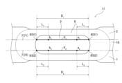
- FIG. 2 is a cross-sectional view schematically showing the periphery of a resistance spot welded portion of a resistance spot welded joint according to one embodiment of the present invention.
- FIG. 3 is a cross-sectional view schematically showing the periphery of a resistance spot welded portion of a resistance spot welded joint according to one embodiment of the present invention.
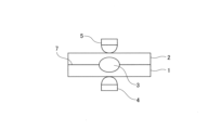
- FIG. 4 is a cross-sectional view illustrating an example of the resistance spot welding method of the present invention.
- FIG. 5 is a schematic diagram for explaining the method of measuring the hardness of the nugget edge in the present invention.
- FIG. 5 is a schematic diagram for explaining the method of measuring the hardness of the nugget edge in the present invention.
- FIG. 6 is a schematic diagram illustrating a method for measuring the average number density of carbides at the edge of a nugget in the present invention.
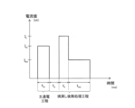
- FIG. 7 is a diagram illustrating an example of an energization pattern of the resistance spot welding method of the present invention.
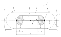
- FIGS. 1-3 show, as an example, cross-sectional views in the plate thickness direction of a resistance spot welded portion and its surroundings in a resistance spot welded joint of the present invention.
- FIG. 1 shows the case where the number of steel plates to be overlapped is two
- FIG. 2 shows the case where the number of steel plates to be overlapped is two and there is a gap between the steel plates
- the present invention is a resistance spot welded joint having a resistance spot welded portion in which a plurality of superimposed steel plates are resistance spot welded.
- the steel sheets to be superimposed include at least one high-strength steel sheet to be described later.
- the number of steel plates mentioned above is not particularly limited, and may be two or more. Although the upper limit of the number of steel sheets described above is not particularly specified, it is preferable to set the number to four or less.
- FIG. 1 shows a resistance spot-welded joint 11 in which two steel plates are superimposed and welded, and a high-strength steel plate is used for the steel plate 1 placed on the lower side and/or the steel plate 2 placed on the upper side.
- a high-strength steel plate is used for the steel plate 2 on the upper side.
- the high-strength steel sheet may have a plating layer as described later, the illustration of the plating layer on the surface of the steel sheet is omitted in FIG.
- the steel sheet mating surfaces (lapped surfaces) 7 of the steel sheets 1 and 2 are formed with resistance spot welds, which will be described below.
- the resistance spot weld (hereinafter referred to as the “weld”) of the resistance spot weld joint 11 includes a nugget 3 and a heat affected zone (HAZ) 6 formed to surround the nugget 3. and
- the nugget 3 is a fusion zone that is formed in a circular (elliptical) shape when the welded zone is viewed from the steel plate surface side.
- the structure and properties in the region of the edge of the nugget 3 are defined as follows. 1 to 3 show cross sections in the plate thickness direction passing through the center of the nugget 3 when the welded portion is viewed from the steel plate surface side.
- two points on the boundary of the nugget 3 that intersect with the overlapping surfaces 7 of the steel plates 1 and 2 are defined as a first end 8 and a second end 9 .
- D (mm) be the length of a line segment X connecting the first end portion 8 and the second end portion 9 .
- the positions on the line segment X toward the center of the nugget 3 are points a and b, and the point a from the first end 8 and the point a from the second end 9
- each distance to b be L (mm).
- the region in the nugget 3 (the hatched region in FIG.
- the hardness (Vickers hardness) of the nugget's most softened region 31 in at least one lap surface 7 is 90% or less of the hardness of the HAZ 6, and the structure of the nugget's most softened region 31 is tempered martensite. and the average number density of carbides having a grain size of 100 nm or more in the nugget's most softened region 31 is 10 or more per 5 ⁇ m 2 of plate cross section.
- the hardness of the nugget most softened region 31 is the lowest softened region even when compared with the hardness of the region in the nugget 3 excluding the nugget most softened region 31 .
- the nugget's most softened region 31 exists on each of the stacked surfaces 71 and 72.
- the nugget 3 located in the middle of the gap and intersecting the straight line Y parallel to the overlapping surface 7 are defined as a first end 8 and a second end 9 .
- the nugget softened region (not shown) on the overlapping surface 71 and/or the nugget softening region (not shown) on the overlapping surface 72 have the following structure and properties: The effects of the present invention can be obtained.
- the "hardness of the nugget's most softened region 31" refers to the Vickers hardness of the nugget's most softened region 31 measured according to JISZ2244 (2020). Specifically, according to the measurement method described in the examples below, at a position 0.2 mm above the overlapping surface 7 of the steel plate in the plate thickness direction, and on a straight line parallel to the overlapping surface 7 (Fig. 5 ) are measured at intervals of 0.2 mm. The measurement area is from the nugget center to the outer edge of HAZ6. The lowest hardness value (most softened value) within this measurement area and within the area of the nugget's most softened area 31 is defined as "the hardness of the nugget's most softened area 31" (see FIG. 5).
- the above “hardness of HAZ6” refers to the average value of Vickers hardness measured in accordance with JISZ2244 (2020) in the region within HAZ6. Specifically, according to the measurement method described in the examples below, at a position 0.2 mm above the overlapping surface 7 of the steel plate in the plate thickness direction, and on a straight line parallel to the overlapping surface 7 (Fig. 5 ) are measured at intervals of 0.2 mm. The measurement area is from the nugget center to the outer edge of HAZ6. In this measurement area, the average value of the hardness in the range from the boundary between the HAZ 6 and the nugget 3 to the outer edge of the HAZ 6 is defined as "HAZ 6 hardness" (see FIG. 5).
- the above-mentioned "hardness of the region in the nugget 3 excluding the nugget most softened region 31" is the nugget Refers to the hardness within 3.
- This hardness can also be measured according to JISZ2244 (2020), similar to the method described above. Specifically, at a position 0.2 mm above the overlapping surface 7 of the steel plate in the plate thickness direction and on a straight line parallel to the overlapping surface 7 (on the straight line Y shown in FIG. 5), 0.2 mm Measured at intervals of The measurement area is from the nugget center to the outer edge of HAZ6.
- the hardness of this nugget most softened region 31 is set to 90% or less of the hardness of the HAZ6. It is preferably 87% or less, more preferably 85% or less, still more preferably 80% or less.
- the lower limit of the hardness of the nugget most softened region 31 is not particularly defined. The nugget's most softened region 31 is tempered the most, and even when the structure of this region 31 is entirely tempered martensite, the target hardness can be obtained.
- the hardness of the nugget most softened region 31 is preferably 55% or more, more preferably 60% or more, and still more preferably 70% or more of the hardness of the HAZ6.
- the hardness of the nugget's most softened region 31 is the lowest softened region even compared to the hardness of the regions within the nugget 3 excluding the nugget's most softened region 31 .
- the toughness of the nugget edge is improved, and the crack propagates through the nugget edge during CTS loading.
- the CTS is improved by causing plug breakage or partial plug breakage of 70% or more of the plug portion.
- the hardness of the nugget's most softened region 31 is preferably 55% or more, more preferably 60% or more, relative to the hardness of the region in the nugget 3 excluding the nugget's most softened region 31. % or more, and even more preferably 75% or more.
- the hardness ratio is preferably 90% or less, more preferably 85% or less.
- the hardness of the nugget's most softened region 31, nugget 3, and HAZ 6 can be measured by the method described in Examples below. The example shown in FIG.
- the measurement is performed at a position 0.2 mm above the overlapping surface of the steel plates. That is, for example, when a high-strength steel plate is used for the steel plate 1 on the lower side, the measurement is performed at "a position 0.2 mm below the overlapping surface".
- the tempered martensite of the nugget softest region 31 should be 50% or more in terms of area ratio with respect to the entire nugget softest region 31 . More preferably, the area ratio is 55% or more, more preferably 60% or more, and even more preferably 65% or more.
- the upper limit of tempered martensite in the nugget's most softened region 31 is not particularly defined. This is because, as described above, even when the structure of the nugget's most softened region 31 is composed of tempered martensite with an area ratio of 100%, the effect of improving toughness and alleviating stress concentration at the nugget edge can be expected.
- the area ratio of tempered martensite in the nugget's most softened region 31 is preferably 100% or less, more preferably 98% or less, and still more preferably 95% or less.
- the residual structure other than the tempered martensite in the nugget's most softened region 31 becomes martensite and/or ferrite.
- the area ratio of a structure other than tempered martensite is large, it becomes difficult to achieve the effect of improving the toughness of the nugget edge and alleviating stress concentration.
- the total area ratio of the remaining structures is preferably 50% or less, more preferably 45% or less, even more preferably 40% or less, and 30% or less. is even more preferred.
- the structure of the nugget's most softened region 31 can be measured by the method described in Examples below.
- the average number density of carbides having a grain size of 100 nm or more in the nugget's most softened region 31 is 10 or more per 5 ⁇ m 2 of plate cross section.
- the grain size of the carbide is set to 100 nm or more is to confirm that coarse carbide is generated as a result of sufficient progress of tempering.
- the particle size of the carbide is preferably 500 nm or less.
- the average number density is set to 10 or more per 5 ⁇ m 2 of plate cross section.
- the average number density is more preferably 15 or more per 5 ⁇ m 2 of plate cross section, more preferably 30 or more per 5 ⁇ m 2 of plate cross section, still more preferably 50 or more per 5 ⁇ m 2 of plate cross section. Note that the upper limit of the average number density is not particularly defined.
- the average number density is preferably 450 or less per 5 ⁇ m 2 of the plate cross section, more preferably 400 or less per 5 ⁇ m 2 of the plate cross section, and more preferably 400 or less per 5 ⁇ m 2 of the plate cross section. More preferably 250 or less, and even more preferably 150 or less per 5 ⁇ m 2 of plate cross section.
- the nugget's most softened region 31 is subdivided into a grid, and observation is started from the position indicated by "1" in FIG. Observation is continued while moving the observation position until satisfies the above average number density.
- the above effects can be obtained.
- the particle size of carbides and the average number density of carbides can be measured by the methods described in Examples described later.
- C 0.05-0.6% C is an element that contributes to strengthening of steel. If the C content is less than 0.05%, the strength of the steel becomes low, and it is extremely difficult to produce a steel sheet with a tensile strength of 780 MPa or more. On the other hand, when the C content exceeds 0.6%, although the strength of the steel sheet increases, the amount of hard martensite becomes excessive and microvoids increase. Furthermore, the nugget and its surrounding HAZ are excessively hardened and embrittled, making it difficult to improve the CTS. Therefore, the C content should be 0.05 to 0.6%. The C content is more preferably 0.10% or more. The C content is more preferably 0.50% or less, still more preferably 0.45% or less.
- Si 0.1-2.0%
- Si content 0.1% or more, it effectively acts to strengthen the steel.
- Si since Si is a ferrite former element, it works predominantly for the generation of ferrite at the nugget edge.
- the Si content should be 0.1 to 2.0%.
- the Si content is more preferably 0.2% or more and more preferably 1.8% or less.
- Mn 1.5-4.0%
- the Mn content is less than 1.5%, a high joint strength can be obtained without long-term cooling as in the present invention.
- the Mn content should be 1.5 to 4.0%.
- the Mn content is more preferably 2.0% or more.
- the Mn content is more preferably 3.7% or less, still more preferably 3.5% or less, even more preferably 3.2% or less, and even more preferably 2.9% or less. .
- P 0.10% or less
- P is an unavoidable impurity, but if the P content exceeds 0.10%, strong segregation appears at the nugget edge of the weld, making it difficult to improve joint strength. Therefore, the P content is set to 0.10% or less.
- the P content is preferably 0.05% or less, more preferably 0.02% or less.
- the lower limit of the P content is not particularly limited. However, excessive reduction causes an increase in cost, so the P content is preferably 0.005% or more.
- the high-strength steel sheet used in the present invention contains each of the above elements, and the balance is Fe and unavoidable impurities.
- the above composition is the basic composition of the high-strength steel sheet.
- one or more elements selected from Al, B, Ca, Cr, Cu, Ni, Mo, Ti, V, and Nb may be added as necessary.
- the following components of Al, B, Ca, Cr, Cu, Ni, Mo, Ti, V, and Nb can be contained as necessary, so these components may be 0%.
- Al 2.0% or less
- Al is an element capable of controlling the structure for refining austenite grains, but if added in a large amount, the toughness deteriorates. Therefore, when Al is contained, the Al content is preferably 2.0% or less.
- the Al content is more preferably 0.10% or less, still more preferably 0.08% or less, and even more preferably 0.07% or less.
- the Al content is more preferably 0.005% or more, more preferably 0.010% or more.
- B 0.005% or less
- B is an element that can improve hardenability and strengthen steel. Therefore, when B is contained, the B content is preferably 0.0005% or more. More preferably, it is 0.0007% or more. However, even if a large amount of B is added, the above effect saturates.
- the B content is more preferably 0.0010% or less.
- Ca 0.005% or less Ca is an element that can contribute to improving the workability of steel. However, if a large amount of Ca is added, the toughness deteriorates. Therefore, when Ca is contained, the Ca content is set to 0.005% or less. The Ca content is more preferably 0.004% or less. The Ca content is preferably 0.001% or more.
- Cr 1.0% or less Cr is an element that can improve strength by improving hardenability. However, if the Cr content exceeds 1.0% and is excessive, the toughness of the HAZ may deteriorate. Therefore, when Cr is contained, the Cr content is set to 1.0% or less. The Cr content is more preferably 0.8% or less. The Cr content is preferably 0.01% or more.
- Cu, Ni, and Mo are elements that can contribute to improving the strength of steel. However, Cu, Ni, and Mo degrade toughness when added in large amounts. Therefore, when these elements are contained, the Cu content is 0.8% or less, the Ni content is 1.0% or less, and the Mo content is 1.0% or less.
- the Cu content is more preferably 0.6% or less.
- the Cu content is preferably 0.005% or more, more preferably 0.006% or more.
- the Ni content is more preferably 0.8% or less.
- the Ni content is preferably 0.01% or more.
- Mo content is more preferably 0.8% or less.
- the Mo content is preferably 0.005% or more, more preferably 0.006% or more.
- Ti 0.20% or less
- Ti is an element that can improve hardenability and strengthen steel. However, when Ti is added in a large amount, it forms carbides, and its precipitation hardening significantly deteriorates the toughness. Therefore, when Ti is contained, the Ti content should be 0.20% or less. The Ti content is more preferably 0.15% or less. The Ti content is preferably 0.003% or more, more preferably 0.004% or more.
- V 0.50% or less
- V is an element capable of strengthening the steel by controlling the structure through precipitation hardening.
- the V content is preferably 0.50% or less.
- the V content is more preferably 0.3% or less.
- the V content is preferably 0.005% or more, more preferably 0.02% or more.
- Nb 0.080% or less Nb improves cross tensile strength and delayed fracture resistance after resistance welding by forming fine carbonitrides. In order to obtain the effect, it is necessary to contain 0.005% or more of Nb. On the other hand, when a large amount of Nb is added, not only does the elongation remarkably decrease, but also the toughness remarkably deteriorates. For this reason, when Nb is contained, the Nb content is made 0.080% or less. The Nb content is more preferably 0.070% or less, still more preferably 0.060% or less. The Nb content is preferably 0.005% or more, more preferably 0.006% or more.
- S 0.005% or less
- S is an element that segregates at grain boundaries and embrittles steel. S is an element that is inevitably included. Furthermore, S reduces the local deformability of sulfides and steel sheets. Therefore, the S content is preferably 0.005% or less.
- the S content is more preferably 0.004% or less, more preferably 0.003% or less.
- the lower limit of the S content is not particularly limited. However, excessive reduction causes an increase in cost, so the S content is preferably 0.001% or more.
- N 0.010% or less
- N is an element that deteriorates the aging resistance of steel.
- N is an element that is inevitably included. Therefore, when N is contained, the N content is preferably 0.010% or less.
- the N content is more preferably 0.008% or less.
- the N content is preferably 0.001% or more.
- O oxygen
- oxygen is an element that deteriorates the cleanliness and toughness of steel by forming nonmetallic inclusions. Therefore, when O is contained, the O content is preferably 0.03% or less. More preferably, the O content is 0.02% or less. Also, the O content is preferably 0.005% or more.
- the high-strength steel sheet having the chemical composition described above preferably has a tensile strength of 780 MPa or more.
- the tensile strength of the high-strength steel sheet is more preferably 1180 MPa or more.
- the CTS may decrease.
- the hardness of the nugget edge is set to the softest hardness in the weld zone, so that the vicinity of the nugget edge has toughness. becomes. As a result, brittle breakage of the nugget end can be prevented. Thereby, the welded part can suppress the decrease in CTS. It should be noted that even a high-strength steel sheet having a tensile strength of less than 780 MPa naturally obtains the above effects.
- the high-strength steel sheet of the present invention can obtain the above effects even if it is a steel sheet (galvanized steel sheet) having a galvanized layer on the steel sheet surface after being subjected to galvanizing treatment.
- a zinc plating layer refers to a plating layer containing zinc as a main component.
- the plating layer containing zinc as a main component includes, for example, a hot-dip galvanizing layer, an electrogalvanizing layer, a Zn--Al plating layer, a Zn--Ni layer, and the like.
- the high-strength steel sheet of the present invention may be an alloyed galvanized steel sheet having an alloyed galvanized layer on the surface of the base material by performing an alloying treatment after performing the above-described galvanizing treatment.
- the steel sheets to be superimposed in the present invention may be a plurality of steel sheets of the same type, or a plurality of steel sheets of different types.
- a steel sheet having a galvanized layer on its surface galvanized steel sheet
- a steel sheet having no galvanized layer on its surface cold-rolled steel sheet
- the thickness of the steel sheet is preferably 0.4 mm to 2.2 mm, for example.
- Resistance spot welding method Next, one embodiment of the resistance spot welding method for manufacturing the resistance spot welded joint of the present invention having the welded portion described above will be described.
- a plate assembly For example, as shown in Fig. 4, two steel plates 1 and 2 are superimposed to form a plate assembly. Then, the pair of welding electrodes 4 and 5 arranged on the lower side and the upper side of the plate set sandwich the plate set, and while applying pressure, the welding conditions are controlled to a predetermined value, and current is applied. As a result, the above-described welded portion can be formed by joining the plates that form the overlapping surfaces 7 of the steel plates (see FIG. 1).
- the main energizing process and the post-tempering heat treatment process are included as the process of energizing the steel sheets 1 and 2 that are sandwiched between the welding electrodes 4 and 5.
- Each step of the present invention will be described in detail below.
- FIG. 7 shows an example of the energization pattern of the present invention.
- the main energization process is performed, and then the post-tempering heat treatment process is performed in which the cooling process, the temperature rising process and the holding process are performed in this order.
- the main energizing step is a step of melting the overlapping surfaces 7 of the steel plates 1 and 2 to form a nugget 3 of a required size (see FIG. 4).
- a nugget is formed by energizing at a current value I m (kA).
- the nugget diameter (mm) used for resistance spot welding (welding) of automotive steel plates is generally 3.0 ⁇ t to 6.0 ⁇ t (t (mm) is the plate thickness). In the present invention, this numerical range is defined as the "target nugget diameter".
- the energizing conditions and pressurizing conditions for forming the nugget 3 are not particularly limited as long as the nugget 3 having the target nugget diameter is obtained.
- the "t” in the above “having a thickness of t (mm)” refers to the thickness of the steel sheet having the smallest thickness among the steel sheets used in the assembly.
- the energizing conditions and pressurizing conditions in the main energizing process are as follows. is preferably controlled to
- the current value I m (kA) in the main energizing step is preferably 3.0 kA to 8.0 kA. If the current value Im is too small, the target nugget diameter cannot be stably obtained. On the other hand, if the current value I m is too large, the nugget diameter may become too large, or the degree of melting of the steel plate may increase, and the melted welds may protrude from the gap between the plates, resulting in a smaller nugget diameter. may become. For this reason, the current value I m is set to 3.0 kA to 8.0 kA.
- the current value Im is more preferably 3.5 kA or more, more preferably 4.0 kA or more.
- the current value I m is more preferably 7.5 kA or less, more preferably 7.0 kA or less.
- the energization time t m (ms) of the main energization step is preferably 120 ms to 400 ms. This is the time for stably forming the nugget 3 having the target nugget diameter, similarly to the current value Im . If the energization time t m is less than 120 ms, there is a concern that nuggets are less likely to form. On the other hand, when the energization time t m exceeds 400 ms, there are concerns that the nugget diameter to be formed may become larger than the target nugget diameter, and workability may be reduced.
- the energization time t m is preferably 200 ms or longer. The energization time is preferably 350 ms or less. However, if the required nugget diameter is obtained, the energization time t m can be set shorter or longer than the above numerical range.
- the pressurizing force is preferably 2.0 kN to 7.0 kN. If the applied pressure is too large, the energized diameter will expand, making it difficult to secure the nugget diameter. On the other hand, if the applied pressure is too small, the energization diameter becomes small, and expulsion tends to occur. For this reason, the pressure is set to 2.0 kN to 7.0 kN.
- the applied pressure is more preferably 3.0 kN or more, and more preferably 6.5 kN or less.
- the applied force may be limited by the equipment capabilities used. The pressure can be set low or high relative to the above numerical range as long as the pressure is such that the required nugget diameter can be obtained.
- the post-tempering heat treatment step is a post-heat treatment step for tempering the nugget end portion of the nugget 3 formed in the main current-applying step to improve toughness.
- the nugget edge structure is tempered martensite by tempering, and the nugget edge (that is, the nugget most softened region 31) is effectively tempered so that the hardness becomes the most softened portion. is.
- the weld zone is subjected to a cooling process, a heating process and a holding process in this order.
- the cooling time t c (ms) is set to 800 ms or longer.
- the cooling time tc is preferably 850 ms or longer, more preferably 900 ms or longer, and still more preferably 1000 ms or longer.
- the upper limit of the cooling time t c (ms) in the cooling process is not particularly limited. Since the steel sheet targeted by the present invention is a steel sheet for automobiles, a long welding time results in a decrease in welding efficiency. Therefore, the cooling time t c (ms) is preferably 2200 (ms) or less, more preferably 2000 (ms) or less.
- the cooling process is followed by the heating process.
- energization post-energization
- appropriate temperature range refers to a tempering temperature range in which the hardness of the nugget end portion (specifically, the nugget's most softened region 31 shown in FIG. 1, etc.) becomes the most softened portion.
- the welding portion is energized at the current value I t (kA) shown in Equation (3) for the energization time t t (ms) shown in Equation (4).
- I t (kA) shown in Equation (3)
- t t (ms) shown in Equation (4).
- 100 ⁇ t t ⁇ 200 (4) Normally, even if the current value of the energization (post-energization) after the main energization step is set constant and the energization is performed, the temperature of the nugget end rises as the energization time of the post-energization increases. Therefore, tempering in the target temperature range is temporary.
- the temperature of the nugget end is shortened to the above-mentioned appropriate temperature, that is, the temperature of Ac 1 point or more.
- a rapid temperature rise in time is of particular importance.
- the structure of the nugget end portion becomes tempered martensite, and can be effectively tempered. If the current value I t in this process is too low, the effect of tempering is reduced. On the other hand, if the current value I t in this process is too high, it will exceed the Ac 3 point, and the structure of the nugget end portion cannot be tempered martensite.
- the current value I t (kA) in the temperature rising process satisfies the relationship of 1.1 ⁇ I m ⁇ I t ⁇ 2.0 ⁇ I m .
- the current value I t is preferably (1.12 ⁇ I m )(kA) or more, more preferably (1.14 ⁇ I m )(kA) or more.
- the current value I t in the temperature rising process exceeds (2.0 ⁇ I m ) (kA)
- the current value I t is preferably (1.7 ⁇ I m ) (kA) or less, more preferably (1.5 ⁇ I m ) (kA) or less.
- the heating process raises the temperature rapidly in a short period of time, so the energization time t t (ms) in the heating process is set to 100 ⁇ tt ⁇ 200.
- the energization time tt is preferably 120 ms or longer, more preferably 140 ms or longer.
- the energization time tt is preferably 180 ms or less, more preferably 160 ms or less.
- the welding portion is energized at the current value I tm (kA) shown in Equation (5) for the energization time t tm (ms) shown in Equation (6).
- the current value I tm (kA) in the holding process should be less than the current value I t (kA) in the heating process. . If the current value I tm in the holding process is equal to or higher than the current value I t (kA) in the temperature rising process, the temperature of the nugget edge may again reach the Ac 1 point or higher.
- the current value I tm is preferably (0.90 ⁇ I t ) (kA) or less, more preferably (0.85 ⁇ I t ) (kA) or less, still more preferably (0.80 ⁇ I t ). (kA) or less.
- the lower limit of the current value I tm (kA) in the holding process is not particularly limited. In order to increase the average number of carbides, an appropriate current value is required to maintain the temperature during the heating process. For that purpose, the average number cannot be increased even if the current value is too low or too high. From the viewpoint of promoting tempering by the holding process, the current value I tm (kA) is preferably (0.10 ⁇ It) (kA) or more, more preferably (0.35 ⁇ It ) (kA) or more. , more preferably (0.40 ⁇ I t )(kA) or more, more preferably (0.50 ⁇ I t )(kA) or more.
- the energization time t tm (ms) in the holding process is set to 300 ms or more and less than 3500 ms.
- the heating process requires a high current value to raise the temperature, but the holding process is a process for tempering the nugget edge, and the energization time ttm may be long.
- the energization time t tm is set to less than 3500 ms. More preferably, it is 2000 ms.
- the energization time t tm is set to 300 ms or longer.
- the energization time t tm is preferably 350 ms or longer, more preferably 400 ms or longer.
- the nugget edge has the above structure and the toughness of the nugget edge is improved. That is, the welded joint obtained by this welding method can suppress interfacial rupture by obtaining a ductile fracture surface, and can be a plug rupture or a partial plug rupture in which most of the plug remains. Thereby, the joint strength (CTS) of the obtained welded joint can be improved. Therefore, a steel sheet containing a relatively large amount of C as the chemical composition of the steel sheet, specifically a high-strength steel sheet having a tensile strength of 780 MPa or more and a C content of 0.05 to 0.6% by mass as described above. Even when the set is welded, the joint strength (CTS) can be further improved.
- CTS joint strength
- steel plates (steel plate A to steel plate K) with a tensile strength of 780 MPa to 1470 MPa and a plate thickness of 0.8 to 1.4 mm shown in Tables 1 and 2 were used.
- the size of the test piece was 150 mm long side and 50 mm short side.
- Table 1 shows the chemical compositions of steel sheets A to K.
- "-" in Table 1 indicates that the element is not intentionally added, and includes not only the case of not containing the element (0%) but also the case of unavoidably containing the element.
- the "GA steel sheet” shown in Table 2 represents the galvannealed steel sheet described above.
- test pieces were stacked as shown in Table 2 to form a board assembly.
- Table 2 the "stacking position of steel sheets” is counted as “first sheet” and “second sheet” in order from the lower steel sheet.
- resistance spot welding was performed under the welding conditions shown in Table 3, a nugget 3 of a required size was formed between the plates, and a resistance spot welded joint was produced.
- Some board sets were made by stacking three steel plates. "-" in Table 3 indicates that the process was not carried out.
- a plurality of steel plates (in the example shown in FIG. 4, the lower steel plate 1 and the upper steel plate 2) are superimposed on each other, and the servo mounted on the C gun Resistance spot welding was performed using a resistance welding machine with a DC power source and a motor pressurization type.
- the pressurizing force during energization was constant, and was 3.5 kN here.
- the welding electrode 4 on the lower side and the welding electrode 5 on the upper side with respect to the plate set each had a tip diameter of 6 mm and a tip curvature radius of 40 mm, and used chromium-copper DR type electrodes.
- Welding was performed by controlling the applied force with the lower welding electrode 4 and the upper welding electrode 5 and using a DC power source.
- the nugget diameter (mm) was formed to be 5.5 ⁇ t (mm) or less when the plate thickness was t (mm). As described above, the above "t" is the thickness of the thinnest steel sheet.
- a cross tension test was performed by the method described below to evaluate the CTS.
- the structure of the nugget edge, the hardness of the nugget and HAZ, the grain size of the carbide at the nugget edge, and the average number density of the carbide were measured by the methods described below.
- the hardness of the nugget and HAZ was measured as follows. The prepared resistance spot welded joint is cut at a position passing through the center of the nugget formed in a circular shape to obtain a test piece, and the test piece is ultrasonically cleaned and then resin-filled. Etching was performed using a picric acid solution to prepare the sample. The HAZ hardness was measured using a Vickers hardness tester according to JISZ2244. A load of 300 gf was applied for 15 seconds.
- the Vickers hardness is a straight line (straight line Y) at a position 0.2 mm above the overlapping surface 7 of the steel plate in the plate thickness direction and parallel to the overlapping surface 7.
- the top was measured at intervals of 0.2 mm.
- the measurement area was from the center of the nugget to the outer edge of the HAZ.
- the Vickers hardness was measured on the steel plate side with the higher strength.
- the Vickers hardness was measured with the upper steel plate as described above.
- the tensile strengths of the two steel plates are different, such as in the plate set d and the plate set e, the Vickers hardness was measured on the side of the steel plate exhibiting the highest tensile strength.
- the measurement was similarly performed at a position 0.2 mm below the overlapping surface 7 of the steel plates in the plate thickness direction.
- the Vickers hardness was measured.
- the intersection of the overlapped surface 7 and the boundary of the nugget is defined as the first end and the second end, and the line segment X connecting the first end and the second end is positioned at 2
- the points be points a and b
- the regions in the nugget where the distances L (mm) from the first end to the point a and from the second end to the point b satisfy the above formula (1) are the nugget most softened regions 31.
- the lowest hardness value (most softened value) was defined as "the hardness of the nugget's most softened area 31".
- the average value of the hardness in the range from the boundary between the HAZ 6 and the nugget 3 to the outer edge of the HAZ 6 in this measurement area was defined as the "hardness of the HAZ 6".
- the average hardness in the range from the center of the nugget 3 to the point a shown in FIG. The hardness of the region within the nugget 3 excluding the most softened region 31”.
- the obtained hardnesses are shown in Table 3, respectively.
- Hardness ratio in Table 3 shows the ratio of the hardness of the nugget's softest region 31 to the hardness of HAZ6.
- the judgment result as to whether or not the hardness ratio satisfies 90% or more is shown.
- the sign “O” indicates a case of passing (90% or more), and the sign “X” indicates a case of failing (less than 90%).
- the average number density (pieces/5 ⁇ m 2 ) of cementite having a particle size of 100 nm or more was observed using a TEM (transmission electron microscope) at a magnification of 10,000 times, and the number density per 5 ⁇ m 2 plate cross section at five locations was obtained. rice field.
- the average value of the obtained values was defined as the average number density per 5 ⁇ m 2 of the plate cross section of carbides having a particle size of 100 nm or more.
- the average number density is shown in Table 4. If the particle size of the carbide becomes large, there is a possibility that it is a precipitate other than the carbide generated by tempering, so the particle size of the carbide is set to 500 nm or less.
- FIG. 6 shows the order of the above observations.
- the carbides may satisfy the above average number density (pieces/5 ⁇ m 2 ) even at one point within the range of distance L (that is, within the nugget's most softened region 31).
- the nugget most softened region 31 is subdivided into a grid pattern, observation is started from the position indicated as "1", and the observation result satisfies the above average number density (that is, pass Observation was continued while moving the observation position until In the first observation, the average number density was observed at a position separated by (0.02 ⁇ D) mm from the position of point 1 toward the center of the nugget.
- the structure in the nugget becomes a homogeneous structure. Therefore, it is possible to obtain the average number density of carbides in the nugget's most softened region by observing with the method described with reference to FIG.
- the sample was prepared such that the nugget's most softened region 31 shown in FIG. 1 was the observation surface.
- SEM scanning electron microscope
- the area ratio of each structure was measured by the point count method (according to ASTM E562-83 (1988)).
- Table 4 shows the area ratio of each tissue obtained.
- TM for structure indicates tempered martensite
- M indicates martensite
- F indicates ferrite.
- resistance spot welded joints in which a plurality of steel plates, including at least one high strength steel plate, are resistance spot welded have excellent shear tensile strength. It was a welded joint. On the other hand, a good welded joint could not be obtained in the comparative example.
- Reference Signs List 1 2, 10 steel plate 3 nugget 31 nugget most softened region 4, 5 welding electrode 6 heat affected zone 7 steel plate mating surface 8 first end 9 second end 11 resistance spot welded joint
Abstract
Description
特許文献1では、ナゲット端部が焼戻しされた溶接部を規定している。具体的に、特許文献1には、ナゲット外層域では、ミクロ組織が、アーム間隔の平均値が12μm以下のデンドライト組織からなり、ミクロ組織に含まれる炭化物の平均粒径が5nm~100nmであり、炭化物の個数密度が2×10⁶個/mm2以上であることを開示している。 Techniques for solving the above problems include, for example,
US Pat. No. 5,400,003 defines a weld where the nugget ends are tempered. Specifically, in
これに対し、後述する本発明では、ナゲット端部において最も硬さを低下させることによってナゲット端部への応力集中を回避し、更にナゲット端部の局所的な焼戻しによってナゲット端部の靭性を向上させている。すなわち、本発明は、ナゲット端部に対して局所的に焼戻しを強く与えるものであり、後述のように炭化物の平均粒形の大きさからも焼戻しの程度が特許文献1と異なることは明らかである。
In contrast, in the present invention, which will be described later, the hardness of the nugget edge is reduced the most to avoid stress concentration on the nugget edge, and the nugget edge is locally tempered to improve the toughness of the nugget edge. I am letting That is, in the present invention, local strong tempering is applied to the nugget edge, and it is clear that the degree of tempering is different from that in
[1] 少なくとも1枚の高強度鋼板を含む2枚以上の鋼板が抵抗スポット溶接された抵抗スポット溶接部を有する抵抗スポット溶接継手であって、
前記高強度鋼板が、質量%で、
C:0.05~0.6%、
Si:0.1~2.0%、
Mn:1.5~4.0%、および
P:0.10%以下
を含有し、残部がFeおよび不可避的不純物を含有する成分組成を有し、
前記鋼板の重ね面と交わるナゲットの境界上の2点を第1端部および第2端部とし、前記第1端部および前記第2端部を結ぶ線分Xの長さをD(mm)とし、前記第1端部および前記第2端部から、前記ナゲットの中心へ向けた前記線分X上の位置を点aおよび点bとし、
前記第1端部から前記点aまでおよび前記第2端部から前記点bまでの各距離L(mm)が、前記線分Xの長さD(mm)に対して式(1)の関係を満たす前記ナゲット内の領域をナゲット最軟化領域とするとき、
少なくとも1つの前記重ね面における、前記ナゲット最軟化領域の硬さが、前記ナゲットを囲む様に形成された熱影響部の硬さに対して90%以下であり、
かつ、前記ナゲット最軟化領域の組織が、焼戻しマルテンサイトを有し、
かつ、前記ナゲット最軟化領域における、粒径が100nm以上の炭化物の平均個数密度が、板断面5μm2当たり10個以上である、抵抗スポット溶接継手。
0<L≦0.10×D ・・・(1)
ただし、前記重ね面において前記鋼板間の隙間がある場合には、前記隙間の中間に位置し前記重ね面に平行な直線Yと交わる前記ナゲットの境界上の2点を前記第1端部および前記第2端部とする。
[2] 前記高強度鋼板の前記成分組成が、さらに、質量%で、
Cu:0.8%以下、
Ni:1.0%以下、
Mo:1.0%以下、
Cr:1.0%以下、
Nb:0.080%以下、
V:0.50%以下、
Ti:0.20%以下、
B:0.005%以下、
Al:2.0%以下、および
Ca:0.005%以下
から選択される1種または2種以上を含有する、[1]に記載の抵抗スポット溶接継手。
[3] 前記高強度鋼板は鋼板表面にめっき層を有する、[1]または[2]に記載の抵抗スポット溶接継手。
[4] [1]~[3]のいずれか1つに記載の抵抗スポット溶接継手の抵抗スポット溶接方法であって、
少なくとも1枚の前記高強度鋼板を含む2枚以上の鋼板を重ね合わせた板組を、1対の溶接電極で挟持し、加圧しながら通電して前記抵抗スポット溶接部を形成するに際し、
前記通電として、
電流値Im(kA)で通電してナゲットを形成する主通電工程と、
式(2)に示す冷却時間tc(ms)を設ける冷却過程と、
次いで、式(3)に示す電流値It(kA)で、式(4)に示す通電時間tt(ms)の間、前記抵抗スポット溶接部を通電する昇温過程と、
次いで、式(5)に示す電流値Itm(kA)で、式(6)に示す通電時間ttm(ms)の間、前記抵抗スポット溶接部を通電する保持過程とを行う、焼戻し後熱処理工程と
を有する、抵抗スポット溶接継手の抵抗スポット溶接方法。
800≦tc ・・・(2)
1.1×Im ≦ It ≦ 2.0×Im ・・・(3)
100 < tt ≦ 200 ・・・(4)
Itm < It ・・・(5)
300 ≦ ttm < 3500 ・・・(6) The present invention is based on the above findings, and has the following gist.
[1] A resistance spot welded joint having a resistance spot weld in which two or more steel plates including at least one high-strength steel plate are resistance spot welded,
The high-strength steel plate is mass%,
C: 0.05 to 0.6%,
Si: 0.1 to 2.0%,
Mn: 1.5 to 4.0%, and P: 0.10% or less, with the balance containing Fe and unavoidable impurities,
The two points on the boundary of the nugget that intersect the overlapping surface of the steel plate are defined as the first end and the second end, and the length of the line segment X connecting the first end and the second end is D (mm) and the positions on the line segment X toward the center of the nugget from the first end and the second end are points a and b,
Each distance L (mm) from the first end to the point a and from the second end to the point b has the relationship of formula (1) with respect to the length D (mm) of the line segment X When the area in the nugget that satisfies
The hardness of the nugget's most softened region in at least one of the overlapping surfaces is 90% or less of the hardness of the heat-affected zone formed to surround the nugget,
and the structure of the nugget's most softened region has tempered martensite,
The resistance spot welded joint, wherein the average number density of carbides having a grain size of 100 nm or more in the nugget's most softened region is 10 or more per 5 μm 2 of plate cross section.
0<L≦0.10×D (1)
However, if there is a gap between the steel plates in the overlapping surface, two points on the boundary of the nugget located in the middle of the gap and intersecting a straight line Y parallel to the overlapping surface are the first end and the Let it be the second end.
[2] The chemical composition of the high-strength steel sheet further, in mass%,
Cu: 0.8% or less,
Ni: 1.0% or less,
Mo: 1.0% or less,
Cr: 1.0% or less,
Nb: 0.080% or less,
V: 0.50% or less,
Ti: 0.20% or less,
B: 0.005% or less,
The resistance spot welded joint according to [1], containing one or more selected from Al: 2.0% or less and Ca: 0.005% or less.
[3] The resistance spot welded joint according to [1] or [2], wherein the high-strength steel sheet has a plating layer on the surface of the steel sheet.
[4] A resistance spot welding method for a resistance spot welded joint according to any one of [1] to [3],
When forming the resistance spot welds by sandwiching a plate set in which two or more steel plates including at least one of the high-strength steel plates are superimposed with a pair of welding electrodes and applying current while applying pressure,
As the energization,
a main energizing step of forming a nugget by energizing at a current value Im (kA);
A cooling process in which the cooling time t c (ms) shown in Equation (2) is provided;
Next, a temperature rising process in which the resistance spot weld is energized at the current value I t (kA) shown in Equation (3) for the energization time t t (ms) shown in Equation (4);
Next, a post-tempering heat treatment is performed in which the resistance spot weld is energized at the current value I tm (kA) shown in Equation (5) for the energization time t tm (ms) shown in Equation (6). A method of resistance spot welding a resistance spot welded joint, comprising:
800≦ tc (2)
1.1×I m ≤ I t ≤ 2.0×I m (3)
100 < t t ≤ 200 (4)
I tm < I t (5)
300≦ ttm <3500 (6)
まず、図1~図3を参照して、本発明の抵抗スポット溶接継手を説明する。図1~図3には、一例として、本発明の抵抗スポット溶接継手における抵抗スポット溶接部およびその周辺の板厚方向断面図を示す。図1は重ね合わせる鋼板の枚数が2枚の場合であり、図2は重ね合わせる鋼板の枚数が2枚で、かつ鋼板間に板隙がある場合であり、図3は重ね合わせる鋼板の枚数が3枚の場合である。 [Resistance spot welding joint]
First, the resistance spot welded joint of the present invention will be described with reference to FIGS. 1-3. 1 to 3 show, as an example, cross-sectional views in the plate thickness direction of a resistance spot welded portion and its surroundings in a resistance spot welded joint of the present invention. FIG. 1 shows the case where the number of steel plates to be overlapped is two, FIG. 2 shows the case where the number of steel plates to be overlapped is two and there is a gap between the steel plates, and FIG. This is the case of three sheets.
本発明の抵抗スポット溶接継手11における、抵抗スポット溶接部について詳細に説明する。図1に示すように、抵抗スポット溶接継手11の抵抗スポット溶接部(以下、「溶接部」と称する)は、ナゲット3と、該ナゲット3を囲むように形成された熱影響部(HAZ)6とを有する。ナゲット3は、溶接部を鋼板表面側から上面視したときに、円状(楕円形)に形成される溶融部である。本発明では、ナゲット3の端部の領域における組織および特性を次のように規定する。
なお、図1~図3には、溶接部を鋼板表面側から上面視したときの、ナゲット3の中心を通る板厚方向断面を示す。 [Resistance spot weld]
The resistance spot welded portion in the resistance spot welded joint 11 of the present invention will be described in detail. As shown in FIG. 1, the resistance spot weld (hereinafter referred to as the “weld”) of the resistance spot weld joint 11 includes a
1 to 3 show cross sections in the plate thickness direction passing through the center of the
0<L≦0.10×D ・・・(1)
ここで、式(1)におけるDは、上記の線分Xの長さを示す。 As shown in FIG. 1 , two points on the boundary of the
0<L≦0.10×D (1)
Here, D in Formula (1) indicates the length of the line segment X described above.
上記ナゲット最軟化領域31の硬さは、該ナゲット最軟化領域31を除くナゲット3内の領域の硬さと比べても、最も低い軟化域となる。 The hardness (Vickers hardness) of the nugget's most
The hardness of the nugget most
図3に示す例では、重ね面71におけるナゲット最軟化領域(図示せず)および/または重ね面72におけるナゲット最軟化領域(図示せず)が、以下の組織および特性を有していれば、本発明の効果を得ることができる。 As shown in FIG. 3, when three or
In the example shown in FIG. 3, if the nugget softened region (not shown) on the overlapping
最初に、本発明における各硬さについて説明する。
上記の「ナゲット最軟化領域31の硬さ」とは、ナゲット最軟化領域31における、JISZ2244(2020年)に準拠して測定したビッカース硬さを指す。具体的には、後述の実施例に記載する測定方法のとおり、鋼板の重ね面7から板厚方向に0.2mm上方の位置で、かつ、該重ね面7と平行となる直線上(図5に示す、直線Y上)を、0.2mmの間隔で計測する。測定領域は、ナゲット中心からHAZ6の外縁までとする。この測定領域内で、かつ、ナゲット最軟化領域31の領域内において、最も低い硬さとなる値(最軟化値)を「ナゲット最軟化領域31の硬さ」とする(図5を参照)。 [Hardness of nugget most softened region 31: 90% or less of hardness of HAZ6]
First, each hardness in the present invention will be explained.
The "hardness of the nugget's most
上記したナゲット最軟化領域31の硬さの下限は、特に規定しない。ナゲット最軟化領域31が最も焼戻され、該領域31の組織が全て焼戻しマルテンサイトとなった場合でも目的とする硬さを得られる。そのため、ナゲット最軟化領域31の硬さは、HAZ6の硬さに対して、好ましくは55%以上とし、より好ましくは60%以上とし、さらに好ましくは70%以上とする。
上述のように、ナゲット最軟化領域31の硬さは、該ナゲット最軟化領域31を除くナゲット3内の領域の硬さと比べても、最も低い軟化域となる。これにより、ナゲット端部の靭性が向上し、CTS負荷時のき裂の進展経路がナゲット端部を通過する破断となる。その結果、プラグ破断、あるいは、プラグ部が7割以上の部分プラグ破断となることで、CTSが向上する。ナゲット最軟化領域31の硬さは、該ナゲット最軟化領域31を除くナゲット3内の領域の硬さに対して、55%以上とすることが好ましく、60%以上とすることがより好ましく、70%以上とすることがさらに好ましく、75%以上とすることがさらに一層好ましい。なお、この硬さの比は、90%以下とすることが好ましく、85%以下とすることがより好ましい。
なお、本発明において、ナゲット最軟化領域31、ナゲット3、HAZ6の硬さは、後述する実施例に記載の方法で、測定することができる。
図5に示す例は鋼板2側に高強度鋼板を用いた場合であり、この場合には上述のように「鋼板の重ね面から0.2mm上方の位置」で計測する。すなわち、例えば下側の鋼板1に高強度鋼板を用いた場合には「重ね面から0.2mm下方の位置」で計測することになる。 When the hardness of the nugget's most
The lower limit of the hardness of the nugget most
As described above, the hardness of the nugget's most
In the present invention, the hardness of the nugget's most
The example shown in FIG. 5 is a case where a high-strength steel plate is used on the
ナゲット最軟化領域31の硬さが上記した硬さの比を満たすためには、この領域31における組織が焼戻しマルテンサイト組織を有するように制御する必要がある。これにより、ナゲット端部の靭性を向上させることができ、ナゲット端部の応力集中を緩和することができる。このような作用効果を得る観点から、ナゲット最軟化領域31の焼戻しマルテンサイトは、ナゲット最軟化領域31全体に対する面積率で50%以上とする。より好ましくは面積率で55%以上とし、さらに好ましくは面積率で60%以上とし、さらに一層好ましくは面積率で65%以上とする。なお、ナゲット最軟化領域31の焼戻しマルテンサイトの上限は特に規定しない。上述のように、ナゲット最軟化領域31の組織が面積率で100%の焼戻しマルテンサイトからなる場合であっても、靭性向上およびナゲット端部の応力集中緩和の効果は見込めるためである。ナゲット最軟化領域31の焼戻しマルテンサイトは、面積率で、好ましくは100%以下とし、より好ましくは98%以下とし、さらに好ましくは95%以下とする。 [Structure of nugget's most softened region 31]
In order for the hardness of the nugget's most
なお、本発明において、ナゲット最軟化領域31の組織は、後述する実施例に記載の方法で、測定することができる。 The residual structure other than the tempered martensite in the nugget's most
In the present invention, the structure of the nugget's most
ナゲット最軟化領域31における粒径が100nm以上の炭化物の平均個数密度は、板断面5μm2当たり10個以上である。 [Carbides in the nugget's most softened region 31]
The average number density of carbides having a grain size of 100 nm or more in the nugget's most
なお、後述の実施例において図6を用いて説明するように、ナゲット最軟化領域31を碁盤の目状に細分化し、図6中の「1」と示した位置から観察を開始し、観察結果が上記平均個数密度を満足するまで、観察位置を移動させながら観察を続ける。本発明では、ナゲット最軟化領域31内における、5μm角の視野の少なくとも1か所で上記炭化物の平均個数密度を満たしていれば、上述の作用効果が得られる。 Further, in the most
In addition, as will be described with reference to FIG. 6 in Examples described later, the nugget's most
本発明の抵抗スポット溶接継手における、高強度鋼板の母材の成分組成の限定理由について説明する。なお、以下の説明において、成分組成の「%」表示は、特に断らない限り「質量%」を指すものとする。 [High strength steel plate]
The reason for limiting the chemical composition of the base material of the high-strength steel plate in the resistance spot welded joint of the present invention will be described. In the following description, "%" in component composition indicates "% by mass" unless otherwise specified.
Cは鋼の強化に寄与する元素である。C含有量が0.05%未満では、鋼の強度が低くなり、引張強度780MPa以上の鋼板を製作することは極めて困難である。一方、C含有量が0.6%を超えると、鋼板の強度は高くなるものの、硬質なマルテンサイト量が過大となり、マイクロボイドが増加する。更にナゲットとその周辺のHAZが過度に硬化し、脆化も進むため、CTSを向上させることは困難である。そのため、C含有量は0.05~0.6%とする。C含有量は、より好ましくは0.10%以上である。C含有量は、より好ましくは0.50%以下であり、さらに好ましくは0.45%以下である。 C: 0.05-0.6%
C is an element that contributes to strengthening of steel. If the C content is less than 0.05%, the strength of the steel becomes low, and it is extremely difficult to produce a steel sheet with a tensile strength of 780 MPa or more. On the other hand, when the C content exceeds 0.6%, although the strength of the steel sheet increases, the amount of hard martensite becomes excessive and microvoids increase. Furthermore, the nugget and its surrounding HAZ are excessively hardened and embrittled, making it difficult to improve the CTS. Therefore, the C content should be 0.05 to 0.6%. The C content is more preferably 0.10% or more. The C content is more preferably 0.50% or less, still more preferably 0.45% or less.
Si含有量が0.1%以上であると、鋼の強化に有効に作用する。また、Siはフェライトフォーマー元素であることから、ナゲット端部のフェライトの生成に優位に働く。一方、Si含有量が2.0%を超えると、鋼は強化されるものの、靱性に悪影響を与えることがある。そのため、Si含有量は0.1~2.0%とする。Si含有量は、より好ましくは0.2%以上であり、より好ましくは1.8%以下である。 Si: 0.1-2.0%
When the Si content is 0.1% or more, it effectively acts to strengthen the steel. In addition, since Si is a ferrite former element, it works predominantly for the generation of ferrite at the nugget edge. On the other hand, when the Si content exceeds 2.0%, although the steel is strengthened, toughness may be adversely affected. Therefore, the Si content should be 0.1 to 2.0%. The Si content is more preferably 0.2% or more and more preferably 1.8% or less.
Mn含有量が1.5%未満であると、本発明のように長時間の冷却を与えずとも、高い継手強度を得ることができる。一方、Mn含有量が4.0%を超えると、溶接部の脆化あるいは脆化に伴う割れが顕著に現れるため、継手強度を向上させることは困難である。そのため、Mn含有量は1.5~4.0%とする。Mn含有量は、より好ましくは2.0%以上である。Mn含有量は、より好ましくは3.7%以下であり、さらに好ましくは3.5%以下であり、さらに一層好ましくは3.2%以下であり、さらに一層好ましくは2.9%以下である。 Mn: 1.5-4.0%
When the Mn content is less than 1.5%, a high joint strength can be obtained without long-term cooling as in the present invention. On the other hand, if the Mn content exceeds 4.0%, embrittlement of the welded portion or cracking due to the embrittlement will remarkably appear, making it difficult to improve the joint strength. Therefore, the Mn content should be 1.5 to 4.0%. The Mn content is more preferably 2.0% or more. The Mn content is more preferably 3.7% or less, still more preferably 3.5% or less, even more preferably 3.2% or less, and even more preferably 2.9% or less. .
Pは不可避的不純物であるが、P含有量が0.10%を超えると、溶接部のナゲット端に強偏析が現れるため継手強度を向上させることは困難である。そのため、P含有量は0.10%以下とする。P含有量は、好ましくは0.05%以下であり、より好ましくは0.02%以下である。なお、P含有量の下限は特に限定されない。ただし、過度の低減はコストの増加を招くので、P含有量は0.005%以上とすることが好ましい。 P: 0.10% or less P is an unavoidable impurity, but if the P content exceeds 0.10%, strong segregation appears at the nugget edge of the weld, making it difficult to improve joint strength. Therefore, the P content is set to 0.10% or less. The P content is preferably 0.05% or less, more preferably 0.02% or less. In addition, the lower limit of the P content is not particularly limited. However, excessive reduction causes an increase in cost, so the P content is preferably 0.005% or more.
Alは、オーステナイト細粒化のため組織制御をすることができる元素であるが、多量に添加すると靭性が劣化する。このため、Alを含有する場合、Al含有量は2.0%以下とすることが好ましい。Al含有量は、より好ましくは0.10%以下とし、さらに好ましくは0.08%以下とし、さらに一層好ましくは0.07%以下とする。Al含有量は、より好ましくは0.005%以上とし、さらに好ましくは0.010%以上とする。 Al: 2.0% or less Al is an element capable of controlling the structure for refining austenite grains, but if added in a large amount, the toughness deteriorates. Therefore, when Al is contained, the Al content is preferably 2.0% or less. The Al content is more preferably 0.10% or less, still more preferably 0.08% or less, and even more preferably 0.07% or less. The Al content is more preferably 0.005% or more, more preferably 0.010% or more.
Bは、焼入れ性を改善して鋼を強化することができる元素である。このため、Bを含有する場合、B含有量は0.0005%以上とすることが好ましい。より好ましくは0.0007%以上とする。しかし、Bを多量に添加しても、上記効果は飽和することから、Bを含有する場合、B含有量は0.005%以下とする。B含有量は、より好ましくは0.0010%以下とする。 B: 0.005% or less B is an element that can improve hardenability and strengthen steel. Therefore, when B is contained, the B content is preferably 0.0005% or more. More preferably, it is 0.0007% or more. However, even if a large amount of B is added, the above effect saturates. The B content is more preferably 0.0010% or less.
Caは、鋼の加工性向上に寄与することができる元素である。しかし、Caを多量に添加すると靭性が劣化する。このため、Caを含有する場合、Ca含有量は0.005%以下とする。Ca含有量は、より好ましくは0.004%以下とする。Ca含有量は、好ましくは0.001%以上とする。 Ca: 0.005% or less Ca is an element that can contribute to improving the workability of steel. However, if a large amount of Ca is added, the toughness deteriorates. Therefore, when Ca is contained, the Ca content is set to 0.005% or less. The Ca content is more preferably 0.004% or less. The Ca content is preferably 0.001% or more.
Crは、焼入れ性の向上により強度を向上させることができる元素である。しかし、Crは1.0%を超えて過剰に含有すると、HAZの靱性が劣化する恐れがある。このため、Crを含有する場合、Cr含有量は1.0%以下とする。Cr含有量は、より好ましくは0.8%以下とする。Cr含有量は、好ましくは0.01%以上とする。 Cr: 1.0% or less Cr is an element that can improve strength by improving hardenability. However, if the Cr content exceeds 1.0% and is excessive, the toughness of the HAZ may deteriorate. Therefore, when Cr is contained, the Cr content is set to 1.0% or less. The Cr content is more preferably 0.8% or less. The Cr content is preferably 0.01% or more.
Cu、Ni、Moは、鋼の強度向上に寄与することができる元素である。しかし、Cu、Ni、Moは、多量に添加すると靭性が劣化する。このため、これらの元素を含有する場合、それぞれ、Cu含有量は0.8%以下とし、Ni含有量は1.0%以下とし、Mo含有量は1.0%以下とする。Cu含有量は、より好ましくは0.6%以下とする。Cu含有量は、好ましくは0.005%以上とし、より好ましくは0.006%以上とする。Ni含有量は、より好ましくは0.8%以下とする。Ni含有量は、好ましくは0.01%以上とする。Mo含有量は、より好ましくは0.8%以下とする。Mo含有量は、好ましくは0.005%以上とし、より好ましくは0.006%以上とする。 Cu: 0.8% or less, Ni: 1.0% or less, Mo: 1.0% or less Cu, Ni, and Mo are elements that can contribute to improving the strength of steel. However, Cu, Ni, and Mo degrade toughness when added in large amounts. Therefore, when these elements are contained, the Cu content is 0.8% or less, the Ni content is 1.0% or less, and the Mo content is 1.0% or less. The Cu content is more preferably 0.6% or less. The Cu content is preferably 0.005% or more, more preferably 0.006% or more. The Ni content is more preferably 0.8% or less. The Ni content is preferably 0.01% or more. Mo content is more preferably 0.8% or less. The Mo content is preferably 0.005% or more, more preferably 0.006% or more.
Tiは、焼入れ性を改善して鋼を強化することができる元素である。しかし、Tiは、多量に添加すると炭化物を形成し、その析出硬化によって靭性が著しく劣化する。このため、Tiを含有する場合、Ti含有量は0.20%以下とする。Ti含有量は、より好ましくは0.15%以下とする。Ti含有量は、好ましくは0.003%以上とし、より好ましくは0.004%以上とする。 Ti: 0.20% or less Ti is an element that can improve hardenability and strengthen steel. However, when Ti is added in a large amount, it forms carbides, and its precipitation hardening significantly deteriorates the toughness. Therefore, when Ti is contained, the Ti content should be 0.20% or less. The Ti content is more preferably 0.15% or less. The Ti content is preferably 0.003% or more, more preferably 0.004% or more.
Vは、析出硬化により組織制御をして鋼を強化することができる元素である。しかし、Vは、多量に添加するとHAZ靱性の劣化につながる。このため、Vを含有する場合、V含有量は0.50%以下とすることが好ましい。V含有量は、より好ましくは0.3%以下とする。V含有量は、好ましくは0.005%以上とし、より好ましくは0.02%以上とする。 V: 0.50% or less V is an element capable of strengthening the steel by controlling the structure through precipitation hardening. However, when V is added in a large amount, it leads to deterioration of HAZ toughness. Therefore, when V is contained, the V content is preferably 0.50% or less. The V content is more preferably 0.3% or less. The V content is preferably 0.005% or more, more preferably 0.02% or more.
Nbは、微細な炭窒化物を形成することで抵抗溶接後の十字引張強度および耐遅れ破壊特性を向上させる。その効果を得るためには、Nbの含有量を0.005%以上含有させることが必要である。一方、多量にNbを添加すると、伸びが著しく低下するだけでなく、靭性を著しく損ねる。このことから、Nbを含有する場合、Nb含有量は0.080%以下とする。Nb含有量は、より好ましくは0.070%以下であり、さらに好ましくは0.060%以下である。Nb含有量は、好ましくは0.005%以上であり、より好ましくは0.006%以上である。 Nb: 0.080% or less Nb improves cross tensile strength and delayed fracture resistance after resistance welding by forming fine carbonitrides. In order to obtain the effect, it is necessary to contain 0.005% or more of Nb. On the other hand, when a large amount of Nb is added, not only does the elongation remarkably decrease, but also the toughness remarkably deteriorates. For this reason, when Nb is contained, the Nb content is made 0.080% or less. The Nb content is more preferably 0.070% or less, still more preferably 0.060% or less. The Nb content is preferably 0.005% or more, more preferably 0.006% or more.
Sは、粒界に偏析して鋼を脆化させる元素である。Sは、不可避的に含まれる元素である。さらに、Sは、硫化物と鋼板の局部変形能を低下させる。そのため、S含有量は0.005%以下とすることが好ましい。S含有量は、より好ましくは0.004%以下とし、さらに好ましくは0.003%以下とする。なお、S含有量の下限は特に限定されない。ただし、過度の低減はコストの増加を招くので、S含有量は0.001%以上とすることが好ましい。 S: 0.005% or less S is an element that segregates at grain boundaries and embrittles steel. S is an element that is inevitably included. Furthermore, S reduces the local deformability of sulfides and steel sheets. Therefore, the S content is preferably 0.005% or less. The S content is more preferably 0.004% or less, more preferably 0.003% or less. In addition, the lower limit of the S content is not particularly limited. However, excessive reduction causes an increase in cost, so the S content is preferably 0.001% or more.
Nは、鋼の耐時効性を劣化させる元素である。Nは、不可避的に含まれる元素である。そのため、Nを含有する場合、N含有量は0.010%以下とすることが好ましい。N含有量は、より好ましくは0.008%以下とする。N含有量は、好ましくは0.001%以上とする。 N: 0.010% or less N is an element that deteriorates the aging resistance of steel. N is an element that is inevitably included. Therefore, when N is contained, the N content is preferably 0.010% or less. The N content is more preferably 0.008% or less. The N content is preferably 0.001% or more.
O(酸素)は非金属介在物を生成することにより、鋼の清浄度、靭性を劣化させる元素である。そのため、Oを含有する場合、O含有量は0.03%以下とすることが好ましい。O含有量は0.02%以下とすることがより好ましい。また、O含有量は0.005%以上とすることが好ましい。 O: 0.03% or less O (oxygen) is an element that deteriorates the cleanliness and toughness of steel by forming nonmetallic inclusions. Therefore, when O is contained, the O content is preferably 0.03% or less. More preferably, the O content is 0.02% or less. Also, the O content is preferably 0.005% or more.
本発明の高強度鋼板は、亜鉛めっき処理を施して、鋼板表面に亜鉛めっき層を有する鋼板(亜鉛めっき鋼板)であっても、上記の効果を得ることができる。亜鉛めっき層とは、亜鉛を主成分とするめっき層を指す。亜鉛を主成分とするめっき層には、例えば、溶融亜鉛めっき層、電気亜鉛めっき層、Zn-Alめっき層およびZn-Ni層等が含まれる。また、本発明の高強度鋼板は、上記の亜鉛めっき処理を施した後に合金化処理を施して、母材表面に合金化亜鉛めっき層を有する合金化亜鉛めっき鋼板であってもよい。 [Types of plating for high-strength steel sheets]
The high-strength steel sheet of the present invention can obtain the above effects even if it is a steel sheet (galvanized steel sheet) having a galvanized layer on the steel sheet surface after being subjected to galvanizing treatment. A zinc plating layer refers to a plating layer containing zinc as a main component. The plating layer containing zinc as a main component includes, for example, a hot-dip galvanizing layer, an electrogalvanizing layer, a Zn--Al plating layer, a Zn--Ni layer, and the like. Further, the high-strength steel sheet of the present invention may be an alloyed galvanized steel sheet having an alloyed galvanized layer on the surface of the base material by performing an alloying treatment after performing the above-described galvanizing treatment.
次に、上記した溶接部を有する本発明の抵抗スポット溶接継手を製造するための抵抗スポット溶接方法の一実施形態について説明する。 [Resistance spot welding method]
Next, one embodiment of the resistance spot welding method for manufacturing the resistance spot welded joint of the present invention having the welded portion described above will be described.
<主通電工程>
主通電工程とは、鋼板1、2の重ね面7を溶融して必要サイズのナゲット3を形成する工程である(図4を参照)。主通電工程では、電流値Im(kA)で通電してナゲットを形成する。 FIG. 7 shows an example of the energization pattern of the present invention. As in the example shown in FIG. 7, the main energization process is performed, and then the post-tempering heat treatment process is performed in which the cooling process, the temperature rising process and the holding process are performed in this order.
<Main energizing process>
The main energizing step is a step of melting the overlapping
焼戻し後熱処理工程とは、主通電工程で形成されたナゲット3におけるナゲット端部を焼戻し、靱性を向上させるための後熱処理の工程である。具体的には、焼戻しによってナゲット端部の組織を焼戻しマルテンサイトとし、さらにナゲット端部(すなわち、上記ナゲット最軟化領域31)の硬さが最軟化部となるように、効果的に焼き戻す工程である。焼戻し後熱処理工程では、主通電工程後、溶接部に対して冷却過程、昇温過程および保持過程をこの順に施す。ナゲット端部の靭性を向上させる効果を得るためには、焼戻し後熱処理工程における各過程の溶接条件を次のように制御することが重要である。 <Heat treatment process after tempering>
The post-tempering heat treatment step is a post-heat treatment step for tempering the nugget end portion of the
まず、主通電工程後、ナゲット端部がマルテンサイト変態を生じる温度まで下げる冷却を行う(冷却過程)。この冷却過程では、後述の焼戻しの効果を十分に得るために、式(2)に示す冷却時間tc(ms)の間、無通電状態を保持することで溶接部を冷却する。
800 ≦ tc ・・・(2)
冷却過程の冷却時間tc(ms)が800ms未満の場合、マルテンサイト変態が十分に起こらず、マルテンサイトが現出しないことによってオーステナイトが残存したままの組織となる。これにより、後続の過程(昇温過程、保持過程)を行っても、そのままオーステナイトが残存し、最終的にはマルテンサイト組織となる。その結果、ナゲット端部は脆化した組織となるため、CTSが向上しない。したがって、冷却時間tc(ms)は800ms以上とする。冷却時間tcは、好ましくは850ms以上とし、より好ましくは900ms以上とし、さらに好ましくは1000ms以上とする。 [Cooling process]
First, after the main energization step, cooling is performed to lower the nugget end portion to a temperature at which martensite transformation occurs (cooling step). In this cooling process, the weld zone is cooled by keeping the non-energized state for the cooling time t c (ms) shown in Equation (2) in order to sufficiently obtain the effect of tempering, which will be described later.
800≦ tc (2)
If the cooling time t c (ms) in the cooling process is less than 800 ms, the martensitic transformation does not occur sufficiently and martensite does not appear, resulting in a structure in which austenite remains. As a result, the austenite remains as it is even after the subsequent processes (heating process, holding process) are performed, and eventually becomes a martensite structure. As a result, the nugget ends have an embrittled structure, and the CTS is not improved. Therefore, the cooling time t c (ms) is set to 800 ms or longer. The cooling time tc is preferably 850 ms or longer, more preferably 900 ms or longer, and still more preferably 1000 ms or longer.
冷却過程に続いて、昇温過程を行う。昇温過程では、前の過程での冷却によってマルテンサイトとなった組織を焼戻すために、適切な温度域に昇温する通電(後通電)を行う。上記の「適切な温度域」とは、ナゲット端部(具体的には、図1などに示すナゲット最軟化領域31)の硬さが最軟化部となるための焼戻し温度域を指す。 [Temperature rising process]
The cooling process is followed by the heating process. In the heating process, in order to temper the structure that has turned into martensite due to the cooling in the previous process, energization (post-energization) is performed to raise the temperature to an appropriate temperature range. The above-mentioned "appropriate temperature range" refers to a tempering temperature range in which the hardness of the nugget end portion (specifically, the nugget's most
1.1×Im ≦ It ≦ 2.0×Im ・・・(3)
100 < tt ≦ 200 ・・・(4)
通常、主通電工程後の通電(後通電)の電流値を一定に設定して通電を行っても、後通電の通電時間が長くなるにつれてナゲット端部の温度が上昇する。そのため、目標とする温度域での焼戻しは一時的なものとなる。 Specifically, in the temperature rising process, the welding portion is energized at the current value I t (kA) shown in Equation (3) for the energization time t t (ms) shown in Equation (4).
1.1×I m ≤ I t ≤ 2.0×I m (3)
100 < t t ≤ 200 (4)
Normally, even if the current value of the energization (post-energization) after the main energization step is set constant and the energization is performed, the temperature of the nugget end rises as the energization time of the post-energization increases. Therefore, tempering in the target temperature range is temporary.
また、この過程での通電時間ttが長すぎるとAc3点を超える可能性が高くなり、さらには散りが発生してしまい、規定のナゲット径を得られない可能性が高くなる。また、施工性も低下することから、適切な通電時間ttを規定する必要がある。 Therefore, in the present invention, by increasing the current of the initial energization after the main energization step (that is, the energization of the temperature rising process), the temperature of the nugget end is shortened to the above-mentioned appropriate temperature, that is, the temperature of Ac 1 point or more. A rapid temperature rise in time is of particular importance. As a result, the structure of the nugget end portion becomes tempered martensite, and can be effectively tempered. If the current value I t in this process is too low, the effect of tempering is reduced. On the other hand, if the current value I t in this process is too high, it will exceed the Ac 3 point, and the structure of the nugget end portion cannot be tempered martensite.
Also, if the energization time tt in this process is too long, there is a high possibility that the Ac 3 point will be exceeded, and moreover, expulsion will occur, increasing the possibility that the specified nugget diameter cannot be obtained. In addition, since workability is also lowered, it is necessary to specify an appropriate energization time tt .
昇温過程に続いて、保持過程を行う。ナゲット端部は、上述の昇温過程での昇温によって焼戻しマルテンサイト組織となるが、この昇温過程のみでは焼戻し時間が短いために一部オーステナイトが残存する。そのため、保持過程を設けることによって通電(後通電)することでナゲット端部を十分に焼戻し、該オーステナイトを焼戻しマルテンサイトとする。 [Holding process]
Following the heating process, a holding process is performed. The end of the nugget becomes a tempered martensitic structure due to the temperature increase in the temperature increase process described above, but a part of the austenite remains in this temperature increase process alone because the tempering time is short. Therefore, by providing a holding process and energizing (post-energizing), the nugget end portion is sufficiently tempered, and the austenite is changed to tempered martensite.
Itm < It ・・・(5)
300 ≦ ttm < 3500 ・・・(6)
ナゲット端部の焼戻しをより効果的に行うために適切な温度制御を行う観点から、保持過程の電流値Itm(kA)は昇温過程の電流値It(kA)未満とする必要がある。保持過程の電流値Itmが昇温過程の電流値It(kA)以上となる場合には、ナゲット端部の温度が再度Ac1点以上の温度となる可能性がある。その結果、ナゲット端部がマルテンサイト組織となり、ナゲット端部の靭性が低くなる懸念がある。電流値Itmは、好ましくは(0.90×It)(kA)以下とし、より好ましくは(0.85×It)(kA)以下とし、さらに好ましくは(0.80×It)(kA)以下とする。 Specifically, in the holding process, the welding portion is energized at the current value I tm (kA) shown in Equation (5) for the energization time t tm (ms) shown in Equation (6).
I tm < I t (5)
300≦ ttm <3500 (6)
From the viewpoint of appropriate temperature control for more effective tempering of the nugget edge, the current value I tm (kA) in the holding process should be less than the current value I t (kA) in the heating process. . If the current value I tm in the holding process is equal to or higher than the current value I t (kA) in the temperature rising process, the temperature of the nugget edge may again reach the Ac 1 point or higher. As a result, the nugget edge becomes a martensite structure, and there is a concern that the toughness of the nugget edge is lowered. The current value I tm is preferably (0.90×I t ) (kA) or less, more preferably (0.85×I t ) (kA) or less, still more preferably (0.80×I t ). (kA) or less.
一方、ナゲット端部の焼戻しを十分に行うためにはAc1点以下の温度で、ナゲット端部が焼戻される必要がある。また、通電時間が短いとマルテンサイトが十分に焼戻されず、保持過程でオーステナイトとなり、最終的にはマルテンサイトとなってしまう。このような理由から、通電時間ttmは300ms以上とする。通電時間ttmは、好ましくは350ms以上とし、より好ましくは400ms以上とする。 Also, the energization time t tm (ms) in the holding process is set to 300 ms or more and less than 3500 ms. The heating process requires a high current value to raise the temperature, but the holding process is a process for tempering the nugget edge, and the energization time ttm may be long. However, from the viewpoint of enforcement efficiency, the energization time t tm is set to less than 3500 ms. More preferably, it is 2000 ms.
On the other hand, in order to sufficiently temper the nugget edge, it is necessary to temper the nugget edge at a temperature of Ac 1 point or less. In addition, if the energization time is short, the martensite is not sufficiently tempered, and becomes austenite during the holding process, and finally becomes martensite. For this reason, the energization time t tm is set to 300 ms or longer. The energization time t tm is preferably 350 ms or longer, more preferably 400 ms or longer.
CTSの評価は、十字引張試験に基づき行った。作製した抵抗スポット溶接継手を用いて、JISZ3137に規定の方法で十字引張試験を行い、CTS(十字引張力)を測定した。測定値がJIS A級(3.4kN)以上であったものに対して表4中の「CTS判定」の欄に記号「○」を付し、JIS A級未満であったものに対して表4中の「CTS判定」の欄に記号「×」を付した。なお、本実施例では、記号「○」の場合を良好と評価し、記号「×」の場合を劣ると評価した。測定結果は表4に示した。 [Evaluation of CTS]
Evaluation of CTS was performed based on a cross tension test. Using the produced resistance spot-welded joint, a cross tension test was performed according to the method specified in JISZ3137, and the CTS (cross tension force) was measured. If the measured value was JIS A grade (3.4 kN) or higher, a symbol "○" was attached to the "CTS judgment" column in Table 4, and if it was less than JIS A grade The column of "CTS judgment" in 4 is marked with a symbol "x". In this example, the case of the symbol "O" was evaluated as good, and the case of the symbol "x" was evaluated as inferior. The measurement results are shown in Table 4.
ナゲットおよびHAZの硬さの測定は、次のように行った。
作製した抵抗スポット溶接継手を円状に形成されたナゲットの中心を通る位置で切断して試験片とし、該試験片を超音波洗浄した後に樹脂埋めを行ったサンプルの板厚断面を研磨し、ピクリン酸溶液を用いてエッチングを行い、サンプルを準備した。HAZの硬さはビッカース硬度計により、JISZ2244に規定の方法で測定した。測定荷重は、300gfの圧子にて15秒負荷する条件で行った。 [Evaluation of hardness]
The hardness of the nugget and HAZ was measured as follows.
The prepared resistance spot welded joint is cut at a position passing through the center of the nugget formed in a circular shape to obtain a test piece, and the test piece is ultrasonically cleaned and then resin-filled. Etching was performed using a picric acid solution to prepare the sample. The HAZ hardness was measured using a Vickers hardness tester according to JISZ2244. A load of 300 gf was applied for 15 seconds.
具体的には、図5に示すように、ビッカース硬さは、鋼板の重ね面7から板厚方向に0.2mm上方の位置で、かつ、該重ね面7と平行となる直線(直線Y)上を、0.2mmの間隔で計測した。測定領域は、ナゲット中心からHAZの外縁までとした。
なお、上側の鋼板と下側の鋼板とで引張強度が異なる場合、ビッカース硬さは、高強度となる鋼板側で計測するものとした。
すなわち、例えば、表2に示す板組aや板組b等のように、2枚の鋼板の引張強度が同一の場合には、上述のように上側の鋼板でビッカース硬さの計測を行った。
また例えば、板組dや板組eのように、2枚の鋼板の引張強度が異なる場合には、最も高い引張強度を示す鋼板側でビッカース硬さの計測を行った。これらの例では、計測対象が下側の鋼板となるため、鋼板の重ね面7から板厚方向に0.2mm下方の位置で、同様に計測した。
また例えば、板組kや板組lのように、本発明の高強度鋼板と比較鋼とを重ね合わせた板組の場合には、高強度鋼板である下側の鋼板側で同様にビッカース硬さの計測を行った。
なお、図1に示すように、重ね面7とナゲットの境界との交点を第1端部および第2端部とし、第1端部および第2端部を結ぶ線分X上に位置する2点を点a、点bとし、第1端部から点aまでおよび第2端部から点bまでの各距離L(mm)が上記式(1)を満たすナゲット内の領域がナゲット最軟化領域31とした。 By the same method as described above, the "hardness of the nugget's softest region", the "hardness of the HAZ" and the "hardness inside the nugget excluding the nugget's softest region" shown in Table 3 were measured.
Specifically, as shown in FIG. 5, the Vickers hardness is a straight line (straight line Y) at a position 0.2 mm above the overlapping
In addition, when the tensile strength differs between the upper steel plate and the lower steel plate, the Vickers hardness was measured on the steel plate side with the higher strength.
That is, for example, when the tensile strength of the two steel plates is the same as in the plate set a and the plate set b shown in Table 2, the Vickers hardness was measured with the upper steel plate as described above. .
For example, when the tensile strengths of the two steel plates are different, such as in the plate set d and the plate set e, the Vickers hardness was measured on the side of the steel plate exhibiting the highest tensile strength. In these examples, since the object to be measured is the lower steel plate, the measurement was similarly performed at a position 0.2 mm below the overlapping
Further, for example, in the case of a plate set in which the high-strength steel plate of the present invention and the comparative steel are superimposed, such as plate set k and plate set l, the Vickers hardness was measured.
In addition, as shown in FIG. 1, the intersection of the overlapped
図1に示すように、ナゲット最軟化領域31の鋼板組織を観察した。これは、得られた抵抗スポット溶接部材から該領域31を切り出し、その板厚断面を研磨後、3%ナイタールで腐食し、TEM(透過型電子顕微鏡)を用いて10000倍の倍率で観察した。さらに、Image-Proを用いて、下限を0.005μmとして、セメンタイトの円相当直径を算出することで、セメンタイトの粒径を求めた。
粒径が100nm以上のセメンタイトの平均個数密度(個/5μm2)は、TEM(透過型電子顕微鏡)を用いて10000倍の倍率で観察し、5箇所の板断面5μm2当たりの個数密度を求めた。得られた値の平均値を、粒径が100nm以上の炭化物の板断面5μm2当たりの平均個数密度とした。該平均個数密度を、表4に示した。なお、炭化物の粒径が大きくなると焼戻しで発生する炭化物以外の析出物である可能性があるため、炭化物の粒径は500nm以下とした。 [Particle size and average number density of carbides in the nugget's most softened region]
As shown in FIG. 1, the steel sheet structure of the nugget's most
The average number density (pieces/5 μm 2 ) of cementite having a particle size of 100 nm or more was observed using a TEM (transmission electron microscope) at a magnification of 10,000 times, and the number density per 5 μm 2 plate cross section at five locations was obtained. rice field. The average value of the obtained values was defined as the average number density per 5 μm 2 of the plate cross section of carbides having a particle size of 100 nm or more. The average number density is shown in Table 4. If the particle size of the carbide becomes large, there is a possibility that it is a precipitate other than the carbide generated by tempering, so the particle size of the carbide is set to 500 nm or less.
ここで、上記の「D」とは、図1に示す線分Xの長さ(mm)であり、その値を表4に示した。
なお、ナゲット内の組織は、板厚方向に対してナゲットの上端から下端までを観察した場合にほぼ均質な組織となる。すなわち、上述の板組a、b、d、e、kおよびlのように、引張強度が同一あるいは異なる高強度鋼板同士の板組や、高強度鋼板と比較鋼との板組であっても、ナゲット内の組織は均質な組織となる。そのため、図6を用いて説明した方法で観察することで、ナゲット最軟化領域における炭化物の平均個数密度を求めることができる。 FIG. 6 shows the order of the above observations. As shown in FIG. 6, the carbides may satisfy the above average number density (pieces/5 μm 2 ) even at one point within the range of distance L (that is, within the nugget's most softened region 31). For example, as shown in FIG. 6, the nugget most
Here, the above "D" is the length (mm) of the line segment X shown in FIG.
The structure in the nugget is substantially homogeneous when observed from the top end to the bottom end of the nugget in the plate thickness direction. That is, even in a combination of high-strength steel sheets with the same or different tensile strengths, or a combination of a high-strength steel sheet and a comparative steel, such as the above-described combination a, b, d, e, k, and l, , the structure in the nugget becomes a homogeneous structure. Therefore, it is possible to obtain the average number density of carbides in the nugget's most softened region by observing with the method described with reference to FIG.
ナゲット端部の組織の観察は、次のように行った。作製した抵抗スポット溶接継手を、楕円状に形成されたナゲットの中心を通る位置で切断して試験片とし、該試験片を超音波洗浄した後に樹脂埋めを行ったサンプルの板厚断面を研磨し、ナイタール溶液を用いてエッチングを行い、サンプルを準備した。 [Organizational evaluation]
Observation of the structure of the nugget edge was performed as follows. The prepared resistance spot welded joint was cut at a position passing through the center of an elliptical nugget to obtain a test piece, and the test piece was ultrasonically cleaned and then resin-filled. , etching was performed using a nital solution to prepare a sample.
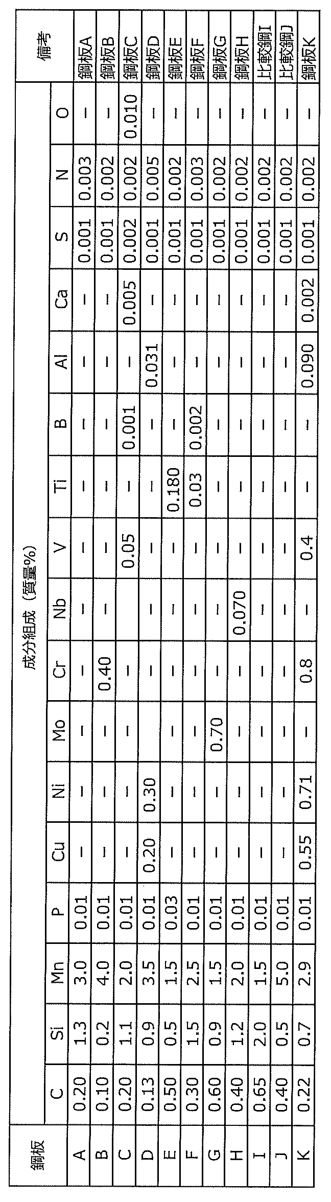
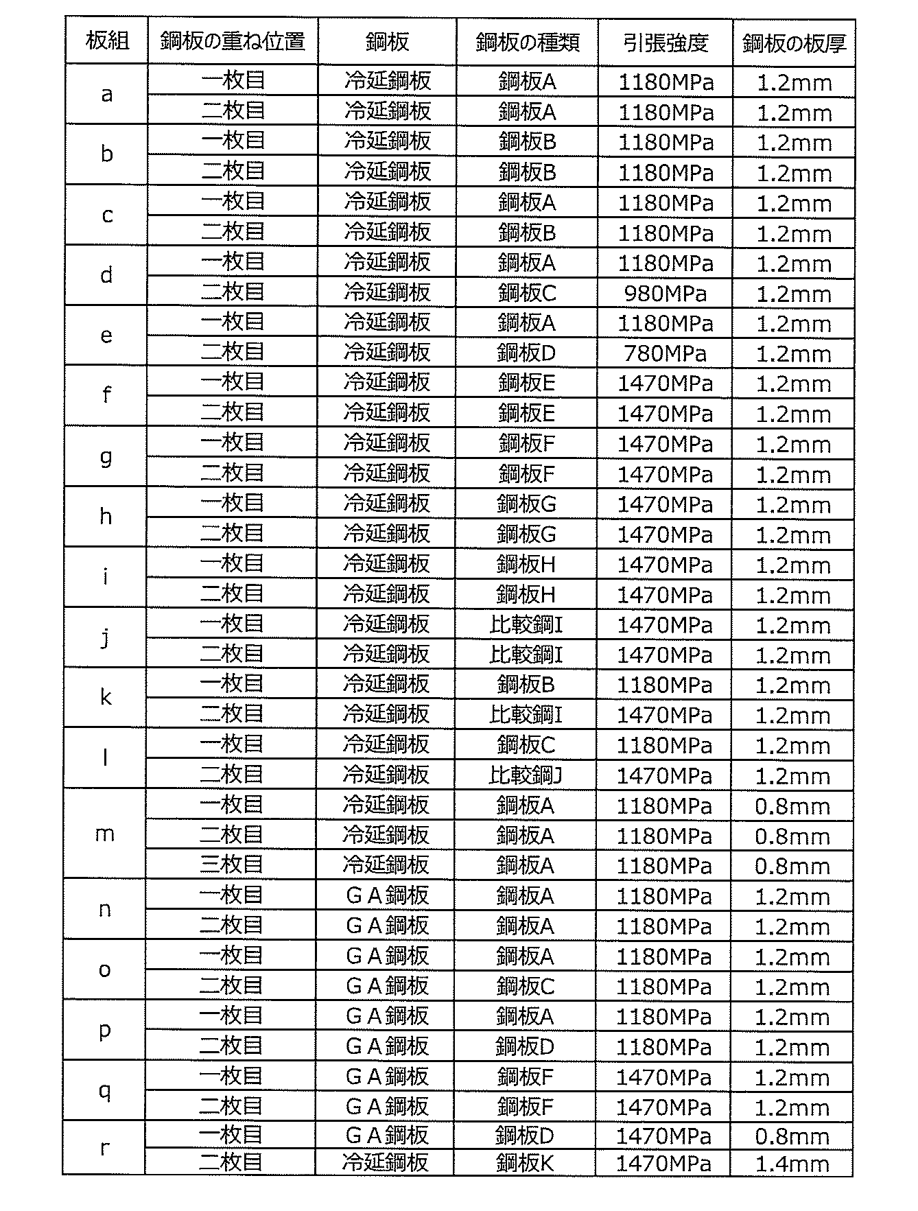
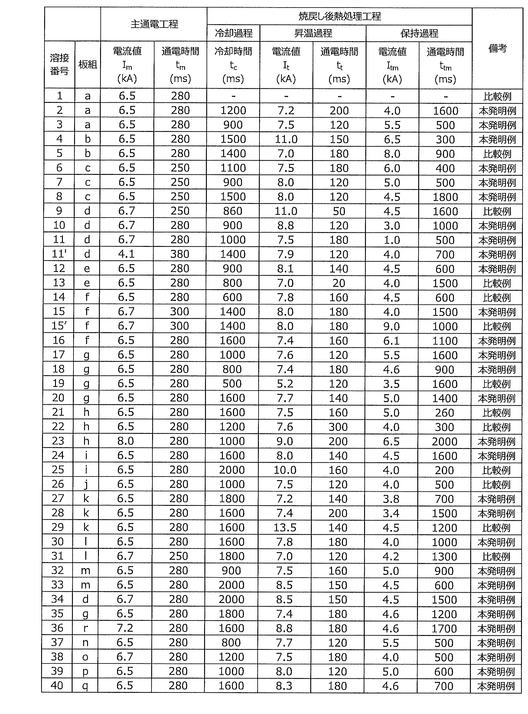
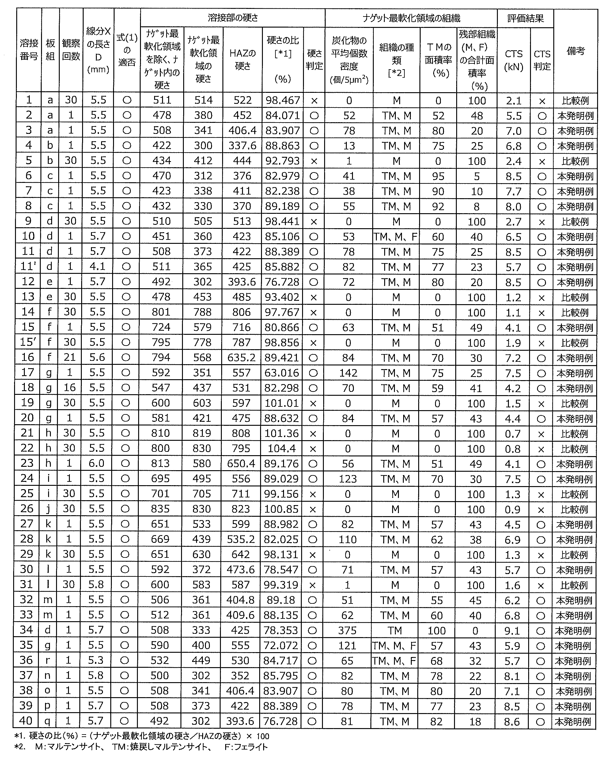
3 ナゲット
31 ナゲット最軟化領域
4、5 溶接電極
6 熱影響部
7 鋼板合わせ面
8 第1端部
9 第2端部
11 抵抗スポット溶接継手
Claims (4)
- 少なくとも1枚の高強度鋼板を含む2枚以上の鋼板が抵抗スポット溶接された抵抗スポット溶接部を有する抵抗スポット溶接継手であって、
前記高強度鋼板が、質量%で、
C:0.05~0.6%、
Si:0.1~2.0%、
Mn:1.5~4.0%、および
P:0.10%以下
を含有し、残部がFeおよび不可避的不純物を含有する成分組成を有し、
前記鋼板の重ね面と交わるナゲットの境界上の2点を第1端部および第2端部とし、前記第1端部および前記第2端部を結ぶ線分Xの長さをD(mm)とし、前記第1端部および前記第2端部から、前記ナゲットの中心へ向けた前記線分X上の位置を点aおよび点bとし、
前記第1端部から前記点aまでおよび前記第2端部から前記点bまでの各距離L(mm)が、前記線分Xの長さD(mm)に対して式(1)の関係を満たす前記ナゲット内の領域をナゲット最軟化領域とするとき、
少なくとも1つの前記重ね面における、前記ナゲット最軟化領域の硬さが、前記ナゲットを囲む様に形成された熱影響部の硬さに対して90%以下であり、
かつ、前記ナゲット最軟化領域の組織が、焼戻しマルテンサイトを有し、
かつ、前記ナゲット最軟化領域における、粒径が100nm以上の炭化物の平均個数密度が、板断面5μm2当たり10個以上である、抵抗スポット溶接継手。
0<L≦0.10×D ・・・(1)
ただし、前記重ね面において前記鋼板間の隙間がある場合には、前記隙間の中間に位置し前記重ね面に平行な直線Yと交わる前記ナゲットの境界上の2点を前記第1端部および前記第2端部とする。 A resistance spot welded joint having a resistance spot weld in which two or more steel plates including at least one high strength steel plate are resistance spot welded, the joint comprising:
The high-strength steel plate is mass%,
C: 0.05 to 0.6%,
Si: 0.1 to 2.0%,
Mn: 1.5 to 4.0%, and P: 0.10% or less, with the balance containing Fe and unavoidable impurities,
The two points on the boundary of the nugget that intersect the overlapping surface of the steel plate are defined as the first end and the second end, and the length of the line segment X connecting the first end and the second end is D (mm) and the positions on the line segment X toward the center of the nugget from the first end and the second end are points a and b,
Each distance L (mm) from the first end to the point a and from the second end to the point b has the relationship of formula (1) with respect to the length D (mm) of the line segment X When the area in the nugget that satisfies
The hardness of the nugget's most softened region in at least one of the overlapping surfaces is 90% or less of the hardness of the heat-affected zone formed to surround the nugget,
and the structure of the nugget's most softened region has tempered martensite,
The resistance spot welded joint, wherein the average number density of carbides having a grain size of 100 nm or more in the nugget's most softened region is 10 or more per 5 μm 2 of plate cross section.
0<L≦0.10×D (1)
However, if there is a gap between the steel plates in the overlapping surface, two points on the boundary of the nugget located in the middle of the gap and intersecting a straight line Y parallel to the overlapping surface are the first end and the Let it be the second end. - 前記高強度鋼板の前記成分組成が、さらに、質量%で、
Cu:0.8%以下、
Ni:1.0%以下、
Mo:1.0%以下、
Cr:1.0%以下、
Nb:0.080%以下、
V:0.50%以下、
Ti:0.20%以下、
B:0.005%以下、
Al:2.0%以下、および
Ca:0.005%以下
から選択される1種または2種以上を含有する、請求項1に記載の抵抗スポット溶接継手。 The chemical composition of the high-strength steel sheet is further, in mass%,
Cu: 0.8% or less,
Ni: 1.0% or less,
Mo: 1.0% or less,
Cr: 1.0% or less,
Nb: 0.080% or less,
V: 0.50% or less,
Ti: 0.20% or less,
B: 0.005% or less,
The resistance spot welded joint according to claim 1, containing one or more selected from Al: 2.0% or less and Ca: 0.005% or less. - 前記高強度鋼板は鋼板表面にめっき層を有する、請求項1または2に記載の抵抗スポット溶接継手。 The resistance spot welded joint according to claim 1 or 2, wherein the high-strength steel sheet has a plating layer on the surface of the steel sheet.
- 請求項1~3のいずれか1項に記載の抵抗スポット溶接継手の抵抗スポット溶接方法であって、
少なくとも1枚の前記高強度鋼板を含む2枚以上の鋼板を重ね合わせた板組を、1対の溶接電極で挟持し、加圧しながら通電して前記抵抗スポット溶接部を形成するに際し、
前記通電として、
電流値Im(kA)で通電してナゲットを形成する主通電工程と、
式(2)に示す冷却時間tc(ms)を設ける冷却過程と、
次いで、式(3)に示す電流値It(kA)で、式(4)に示す通電時間tt(ms)の間、前記抵抗スポット溶接部を通電する昇温過程と、
次いで、式(5)に示す電流値Itm(kA)で、式(6)に示す通電時間ttm(ms)の間、前記抵抗スポット溶接部を通電する保持過程とを行う、焼戻し後熱処理工程と
を有する、抵抗スポット溶接継手の抵抗スポット溶接方法。
800≦tc ・・・(2)
1.1×Im ≦ It ≦ 2.0×Im ・・・(3)
100 < tt ≦ 200 ・・・(4)
Itm < It ・・・(5)
300 ≦ ttm < 3500 ・・・(6) A resistance spot welding method for a resistance spot welded joint according to any one of claims 1 to 3,
When forming the resistance spot welds by sandwiching a plate set in which two or more steel plates including at least one of the high-strength steel plates are superimposed with a pair of welding electrodes and applying current while applying pressure,
As the energization,
a main energizing step of forming a nugget by energizing at a current value Im (kA);
A cooling process in which the cooling time t c (ms) shown in Equation (2) is provided;
Next, a temperature rising process in which the resistance spot weld is energized at the current value I t (kA) shown in Equation (3) for the energization time t t (ms) shown in Equation (4);
Next, a post-tempering heat treatment is performed in which the resistance spot weld is energized at the current value I tm (kA) shown in Equation (5) for the energization time t tm (ms) shown in Equation (6). A method of resistance spot welding a resistance spot welded joint, comprising:
800≦ tc (2)
1.1×I m ≤ I t ≤ 2.0×I m (3)
100 < t t ≤ 200 (4)
I tm < I t (5)
300≦ ttm <3500 (6)
Priority Applications (4)
| Application Number | Priority Date | Filing Date | Title |
|---|---|---|---|
| KR1020247004481A KR20240026245A (en) | 2021-08-19 | 2022-07-21 | Resistance spot welded joint and its resistance spot welding method |
| CN202280055420.2A CN117897251A (en) | 2021-08-19 | 2022-07-21 | Resistance spot welding joint and resistance spot welding method thereof |
| EP22858244.1A EP4353393A1 (en) | 2021-08-19 | 2022-07-21 | Resistance spot welding joint and resistance spot welding method therefor |
| JP2022566088A JP7473009B2 (en) | 2021-08-19 | 2022-07-21 | Resistance spot welded joint and resistance spot welding method thereof |
Applications Claiming Priority (2)
| Application Number | Priority Date | Filing Date | Title |
|---|---|---|---|
| JP2021-134058 | 2021-08-19 | ||
| JP2021134058 | 2021-08-19 |
Publications (1)
| Publication Number | Publication Date |
|---|---|
| WO2023021922A1 true WO2023021922A1 (en) | 2023-02-23 |
Family
ID=85240589
Family Applications (1)
| Application Number | Title | Priority Date | Filing Date |
|---|---|---|---|
| PCT/JP2022/028412 WO2023021922A1 (en) | 2021-08-19 | 2022-07-21 | Resistance spot welding joint and resistance spot welding method therefor |
Country Status (5)
| Country | Link |
|---|---|
| EP (1) | EP4353393A1 (en) |
| JP (1) | JP7473009B2 (en) |
| KR (1) | KR20240026245A (en) |
| CN (1) | CN117897251A (en) |
| WO (1) | WO2023021922A1 (en) |
Citations (8)
| Publication number | Priority date | Publication date | Assignee | Title |
|---|---|---|---|---|
| JP5043236B2 (en) | 2009-08-31 | 2012-10-10 | 新日本製鐵株式会社 | Spot welding joint and spot welding method |
| JP5182855B2 (en) | 2007-11-28 | 2013-04-17 | 日産自動車株式会社 | Resistance welded steel sheet |
| JP2013128945A (en) * | 2011-12-21 | 2013-07-04 | Jfe Steel Corp | Resistance spot welding method |
| JP5895430B2 (en) | 2011-10-04 | 2016-03-30 | Jfeスチール株式会社 | Resistance spot welding joint and resistance spot welding method of high strength thin steel sheet |
| WO2018038045A1 (en) * | 2016-08-22 | 2018-03-01 | Jfeスチール株式会社 | Automobile member having resistance weld |
| JP2020069525A (en) * | 2018-11-02 | 2020-05-07 | 日本製鉄株式会社 | Method for manufacturing resistance spot welding joint |
| JP2020082104A (en) * | 2018-11-19 | 2020-06-04 | 株式会社神戸製鋼所 | Joint structure and joint structure manufacturing method |
| WO2020240961A1 (en) * | 2019-05-28 | 2020-12-03 | Jfeスチール株式会社 | Resistance spot welding unit and resistance spot welding method, and resistance spot welded joint and method for manufacturing resistance spot welded joint |
Family Cites Families (2)
| Publication number | Priority date | Publication date | Assignee | Title |
|---|---|---|---|---|
| JPS5043236Y1 (en) | 1970-09-04 | 1975-12-10 | ||
| JPH05182855A (en) | 1991-12-27 | 1993-07-23 | Toshiba Lighting & Technol Corp | Manufacture of choke coil |
-
2022
- 2022-07-21 EP EP22858244.1A patent/EP4353393A1/en active Pending
- 2022-07-21 JP JP2022566088A patent/JP7473009B2/en active Active
- 2022-07-21 WO PCT/JP2022/028412 patent/WO2023021922A1/en active Application Filing
- 2022-07-21 KR KR1020247004481A patent/KR20240026245A/en unknown
- 2022-07-21 CN CN202280055420.2A patent/CN117897251A/en active Pending
Patent Citations (8)
| Publication number | Priority date | Publication date | Assignee | Title |
|---|---|---|---|---|
| JP5182855B2 (en) | 2007-11-28 | 2013-04-17 | 日産自動車株式会社 | Resistance welded steel sheet |
| JP5043236B2 (en) | 2009-08-31 | 2012-10-10 | 新日本製鐵株式会社 | Spot welding joint and spot welding method |
| JP5895430B2 (en) | 2011-10-04 | 2016-03-30 | Jfeスチール株式会社 | Resistance spot welding joint and resistance spot welding method of high strength thin steel sheet |
| JP2013128945A (en) * | 2011-12-21 | 2013-07-04 | Jfe Steel Corp | Resistance spot welding method |
| WO2018038045A1 (en) * | 2016-08-22 | 2018-03-01 | Jfeスチール株式会社 | Automobile member having resistance weld |
| JP2020069525A (en) * | 2018-11-02 | 2020-05-07 | 日本製鉄株式会社 | Method for manufacturing resistance spot welding joint |
| JP2020082104A (en) * | 2018-11-19 | 2020-06-04 | 株式会社神戸製鋼所 | Joint structure and joint structure manufacturing method |
| WO2020240961A1 (en) * | 2019-05-28 | 2020-12-03 | Jfeスチール株式会社 | Resistance spot welding unit and resistance spot welding method, and resistance spot welded joint and method for manufacturing resistance spot welded joint |
Also Published As
| Publication number | Publication date |
|---|---|
| JP7473009B2 (en) | 2024-04-23 |
| KR20240026245A (en) | 2024-02-27 |
| JPWO2023021922A1 (en) | 2023-02-23 |
| CN117897251A (en) | 2024-04-16 |
| EP4353393A1 (en) | 2024-04-17 |
Similar Documents
| Publication | Publication Date | Title |
|---|---|---|
| KR101805284B1 (en) | Spot welded joint and spot welding method | |
| JP6447752B2 (en) | Automotive parts having resistance welds | |
| JP5142068B2 (en) | High strength steel plate for resistance spot welding and joining method thereof | |
| WO2013161937A1 (en) | Spot-welding joint | |
| WO2020240961A1 (en) | Resistance spot welding unit and resistance spot welding method, and resistance spot welded joint and method for manufacturing resistance spot welded joint | |
| JP6036438B2 (en) | High strength resistance welded joint and manufacturing method thereof | |
| JP7276614B2 (en) | Automobile member and its resistance spot welding method | |
| WO2023021922A1 (en) | Resistance spot welding joint and resistance spot welding method therefor | |
| JP5008173B2 (en) | High strength steel plate for resistance welding and joining method thereof | |
| JP2021154390A (en) | Resistance-spot welding method and joint manufacturing method | |
| WO2023063097A1 (en) | Resistance spot welding joint and resistance spot welding method for same | |
| JP7332065B1 (en) | Resistance spot welding joint and resistance spot welding method thereof | |
| JP7473861B1 (en) | Resistance Spot Welding Method | |
| JP7347716B1 (en) | Resistance spot welding joints and resistance spot welding methods | |
| JP5008172B2 (en) | High strength steel plate for resistance welding and joining method thereof | |
| JP7468825B1 (en) | Method for manufacturing resistance spot welded joints | |
| JP6777270B1 (en) | Resistance spot welds and resistance spot welds, and resistance spot weld joints and resistance spot weld joint manufacturing methods | |
| KR20240051267A (en) | Resistance spot welding seam and its resistance spot welding method | |
| WO2022107580A1 (en) | Plated steel sheet for spot welding use, joining member, automotive member, and method for manufacturing joining member | |
| JP7327676B2 (en) | Resistance spot welding member and its resistance spot welding method | |
| WO2023080076A1 (en) | Resistance spot welded member, and resistance spot welding method for same | |
| KR20240051268A (en) | Resistance spot welding seam and its resistance spot welding method |
Legal Events
| Date | Code | Title | Description |
|---|---|---|---|
| ENP | Entry into the national phase |
Ref document number: 2022566088 Country of ref document: JP Kind code of ref document: A |
|
| 121 | Ep: the epo has been informed by wipo that ep was designated in this application |
Ref document number: 22858244 Country of ref document: EP Kind code of ref document: A1 |
|
| WWE | Wipo information: entry into national phase |
Ref document number: 2022858244 Country of ref document: EP |
|
| ENP | Entry into the national phase |
Ref document number: 20247004481 Country of ref document: KR Kind code of ref document: A |
|
| WWE | Wipo information: entry into national phase |
Ref document number: 1020247004481 Country of ref document: KR |
|
| WWE | Wipo information: entry into national phase |
Ref document number: 2401000797 Country of ref document: TH |
|
| ENP | Entry into the national phase |
Ref document number: 2022858244 Country of ref document: EP Effective date: 20240113 |
|
| NENP | Non-entry into the national phase |
Ref country code: DE |