WO2023007924A1 - 電子部品収容システム - Google Patents
電子部品収容システム Download PDFInfo
- Publication number
- WO2023007924A1 WO2023007924A1 PCT/JP2022/021113 JP2022021113W WO2023007924A1 WO 2023007924 A1 WO2023007924 A1 WO 2023007924A1 JP 2022021113 W JP2022021113 W JP 2022021113W WO 2023007924 A1 WO2023007924 A1 WO 2023007924A1
- Authority
- WO
- WIPO (PCT)
- Prior art keywords
- rfid tag
- electronic component
- information
- input
- information related
- Prior art date
Links
- 238000004519 manufacturing process Methods 0.000 claims description 35
- 101100456831 Caenorhabditis elegans sams-5 gene Proteins 0.000 description 44
- 238000000034 method Methods 0.000 description 11
- 230000032258 transport Effects 0.000 description 9
- 239000011347 resin Substances 0.000 description 7
- 229920005989 resin Polymers 0.000 description 7
- 238000007689 inspection Methods 0.000 description 4
- 230000004308 accommodation Effects 0.000 description 3
- 239000000463 material Substances 0.000 description 3
- 239000000853 adhesive Substances 0.000 description 2
- 230000001070 adhesive effect Effects 0.000 description 2
- 239000004065 semiconductor Substances 0.000 description 2
- 239000003990 capacitor Substances 0.000 description 1
- 239000003985 ceramic capacitor Substances 0.000 description 1
- 238000010586 diagram Methods 0.000 description 1
- 230000000694 effects Effects 0.000 description 1
- 230000002452 interceptive effect Effects 0.000 description 1
- 238000012986 modification Methods 0.000 description 1
- 230000004048 modification Effects 0.000 description 1
- 238000004806 packaging method and process Methods 0.000 description 1
- 238000012858 packaging process Methods 0.000 description 1
Images


Classifications
-
- G—PHYSICS
- G06—COMPUTING; CALCULATING OR COUNTING
- G06K—GRAPHICAL DATA READING; PRESENTATION OF DATA; RECORD CARRIERS; HANDLING RECORD CARRIERS
- G06K17/00—Methods or arrangements for effecting co-operative working between equipments covered by two or more of main groups G06K1/00 - G06K15/00, e.g. automatic card files incorporating conveying and reading operations
- G06K17/0022—Methods or arrangements for effecting co-operative working between equipments covered by two or more of main groups G06K1/00 - G06K15/00, e.g. automatic card files incorporating conveying and reading operations arrangements or provisions for transferring data to distant stations, e.g. from a sensing device
- G06K17/0029—Methods or arrangements for effecting co-operative working between equipments covered by two or more of main groups G06K1/00 - G06K15/00, e.g. automatic card files incorporating conveying and reading operations arrangements or provisions for transferring data to distant stations, e.g. from a sensing device the arrangement being specially adapted for wireless interrogation of grouped or bundled articles tagged with wireless record carriers
-
- B—PERFORMING OPERATIONS; TRANSPORTING
- B65—CONVEYING; PACKING; STORING; HANDLING THIN OR FILAMENTARY MATERIAL
- B65G—TRANSPORT OR STORAGE DEVICES, e.g. CONVEYORS FOR LOADING OR TIPPING, SHOP CONVEYOR SYSTEMS OR PNEUMATIC TUBE CONVEYORS
- B65G1/00—Storing articles, individually or in orderly arrangement, in warehouses or magazines
- B65G1/02—Storage devices
- B65G1/04—Storage devices mechanical
- B65G1/137—Storage devices mechanical with arrangements or automatic control means for selecting which articles are to be removed
- B65G1/1371—Storage devices mechanical with arrangements or automatic control means for selecting which articles are to be removed with data records
-
- G—PHYSICS
- G06—COMPUTING; CALCULATING OR COUNTING
- G06K—GRAPHICAL DATA READING; PRESENTATION OF DATA; RECORD CARRIERS; HANDLING RECORD CARRIERS
- G06K19/00—Record carriers for use with machines and with at least a part designed to carry digital markings
- G06K19/06—Record carriers for use with machines and with at least a part designed to carry digital markings characterised by the kind of the digital marking, e.g. shape, nature, code
- G06K19/067—Record carriers with conductive marks, printed circuits or semiconductor circuit elements, e.g. credit or identity cards also with resonating or responding marks without active components
- G06K19/07—Record carriers with conductive marks, printed circuits or semiconductor circuit elements, e.g. credit or identity cards also with resonating or responding marks without active components with integrated circuit chips
- G06K19/0723—Record carriers with conductive marks, printed circuits or semiconductor circuit elements, e.g. credit or identity cards also with resonating or responding marks without active components with integrated circuit chips the record carrier comprising an arrangement for non-contact communication, e.g. wireless communication circuits on transponder cards, non-contact smart cards or RFIDs
-
- G—PHYSICS
- G06—COMPUTING; CALCULATING OR COUNTING
- G06K—GRAPHICAL DATA READING; PRESENTATION OF DATA; RECORD CARRIERS; HANDLING RECORD CARRIERS
- G06K19/00—Record carriers for use with machines and with at least a part designed to carry digital markings
- G06K19/06—Record carriers for use with machines and with at least a part designed to carry digital markings characterised by the kind of the digital marking, e.g. shape, nature, code
- G06K19/067—Record carriers with conductive marks, printed circuits or semiconductor circuit elements, e.g. credit or identity cards also with resonating or responding marks without active components
- G06K19/07—Record carriers with conductive marks, printed circuits or semiconductor circuit elements, e.g. credit or identity cards also with resonating or responding marks without active components with integrated circuit chips
- G06K19/077—Constructional details, e.g. mounting of circuits in the carrier
- G06K19/07749—Constructional details, e.g. mounting of circuits in the carrier the record carrier being capable of non-contact communication, e.g. constructional details of the antenna of a non-contact smart card
- G06K19/07773—Antenna details
-
- G—PHYSICS
- G06—COMPUTING; CALCULATING OR COUNTING
- G06K—GRAPHICAL DATA READING; PRESENTATION OF DATA; RECORD CARRIERS; HANDLING RECORD CARRIERS
- G06K7/00—Methods or arrangements for sensing record carriers, e.g. for reading patterns
- G06K7/10—Methods or arrangements for sensing record carriers, e.g. for reading patterns by electromagnetic radiation, e.g. optical sensing; by corpuscular radiation
- G06K7/10009—Methods or arrangements for sensing record carriers, e.g. for reading patterns by electromagnetic radiation, e.g. optical sensing; by corpuscular radiation sensing by radiation using wavelengths larger than 0.1 mm, e.g. radio-waves or microwaves
- G06K7/10297—Methods or arrangements for sensing record carriers, e.g. for reading patterns by electromagnetic radiation, e.g. optical sensing; by corpuscular radiation sensing by radiation using wavelengths larger than 0.1 mm, e.g. radio-waves or microwaves arrangements for handling protocols designed for non-contact record carriers such as RFIDs NFCs, e.g. ISO/IEC 14443 and 18092
-
- G—PHYSICS
- G06—COMPUTING; CALCULATING OR COUNTING
- G06K—GRAPHICAL DATA READING; PRESENTATION OF DATA; RECORD CARRIERS; HANDLING RECORD CARRIERS
- G06K7/00—Methods or arrangements for sensing record carriers, e.g. for reading patterns
- G06K7/10—Methods or arrangements for sensing record carriers, e.g. for reading patterns by electromagnetic radiation, e.g. optical sensing; by corpuscular radiation
- G06K7/10009—Methods or arrangements for sensing record carriers, e.g. for reading patterns by electromagnetic radiation, e.g. optical sensing; by corpuscular radiation sensing by radiation using wavelengths larger than 0.1 mm, e.g. radio-waves or microwaves
- G06K7/10366—Methods or arrangements for sensing record carriers, e.g. for reading patterns by electromagnetic radiation, e.g. optical sensing; by corpuscular radiation sensing by radiation using wavelengths larger than 0.1 mm, e.g. radio-waves or microwaves the interrogation device being adapted for miscellaneous applications
-
- H—ELECTRICITY
- H05—ELECTRIC TECHNIQUES NOT OTHERWISE PROVIDED FOR
- H05K—PRINTED CIRCUITS; CASINGS OR CONSTRUCTIONAL DETAILS OF ELECTRIC APPARATUS; MANUFACTURE OF ASSEMBLAGES OF ELECTRICAL COMPONENTS
- H05K13/00—Apparatus or processes specially adapted for manufacturing or adjusting assemblages of electric components
- H05K13/0084—Containers and magazines for components, e.g. tube-like magazines
-
- H—ELECTRICITY
- H05—ELECTRIC TECHNIQUES NOT OTHERWISE PROVIDED FOR
- H05K—PRINTED CIRCUITS; CASINGS OR CONSTRUCTIONAL DETAILS OF ELECTRIC APPARATUS; MANUFACTURE OF ASSEMBLAGES OF ELECTRICAL COMPONENTS
- H05K13/00—Apparatus or processes specially adapted for manufacturing or adjusting assemblages of electric components
- H05K13/02—Feeding of components
-
- H—ELECTRICITY
- H05—ELECTRIC TECHNIQUES NOT OTHERWISE PROVIDED FOR
- H05K—PRINTED CIRCUITS; CASINGS OR CONSTRUCTIONAL DETAILS OF ELECTRIC APPARATUS; MANUFACTURE OF ASSEMBLAGES OF ELECTRICAL COMPONENTS
- H05K13/00—Apparatus or processes specially adapted for manufacturing or adjusting assemblages of electric components
- H05K13/08—Monitoring manufacture of assemblages
- H05K13/087—Equipment tracking or labelling, e.g. tracking of nozzles, feeders or mounting heads
-
- B—PERFORMING OPERATIONS; TRANSPORTING
- B65—CONVEYING; PACKING; STORING; HANDLING THIN OR FILAMENTARY MATERIAL
- B65G—TRANSPORT OR STORAGE DEVICES, e.g. CONVEYORS FOR LOADING OR TIPPING, SHOP CONVEYOR SYSTEMS OR PNEUMATIC TUBE CONVEYORS
- B65G2201/00—Indexing codes relating to handling devices, e.g. conveyors, characterised by the type of product or load being conveyed or handled
- B65G2201/02—Articles
- B65G2201/0235—Containers
-
- G—PHYSICS
- G06—COMPUTING; CALCULATING OR COUNTING
- G06K—GRAPHICAL DATA READING; PRESENTATION OF DATA; RECORD CARRIERS; HANDLING RECORD CARRIERS
- G06K17/00—Methods or arrangements for effecting co-operative working between equipments covered by two or more of main groups G06K1/00 - G06K15/00, e.g. automatic card files incorporating conveying and reading operations
-
- H—ELECTRICITY
- H04—ELECTRIC COMMUNICATION TECHNIQUE
- H04B—TRANSMISSION
- H04B1/00—Details of transmission systems, not covered by a single one of groups H04B3/00 - H04B13/00; Details of transmission systems not characterised by the medium used for transmission
- H04B1/59—Responders; Transponders
-
- Y—GENERAL TAGGING OF NEW TECHNOLOGICAL DEVELOPMENTS; GENERAL TAGGING OF CROSS-SECTIONAL TECHNOLOGIES SPANNING OVER SEVERAL SECTIONS OF THE IPC; TECHNICAL SUBJECTS COVERED BY FORMER USPC CROSS-REFERENCE ART COLLECTIONS [XRACs] AND DIGESTS
- Y02—TECHNOLOGIES OR APPLICATIONS FOR MITIGATION OR ADAPTATION AGAINST CLIMATE CHANGE
- Y02P—CLIMATE CHANGE MITIGATION TECHNOLOGIES IN THE PRODUCTION OR PROCESSING OF GOODS
- Y02P90/00—Enabling technologies with a potential contribution to greenhouse gas [GHG] emissions mitigation
- Y02P90/30—Computing systems specially adapted for manufacturing
Definitions
- the present invention relates to an electronic component housing system.
- a parts manufacturer that manufactures small electronic parts such as semiconductor chips and capacitor chips stores a plurality of manufactured electronic parts in one container, transports and stores them in the factory, and sets the container together. Shipment to the manufacturer is carried out.
- the form of the container there are a carrier tape in which electronic components are individually held and wound around a reel, a magazine in which electronic components are arranged and stored, and a bulk in which electronic components are stored in a loose state, that is, in a bulk state.
- a case, bagging method, and the like are known (see, for example, Patent Document 1).
- a technique used by a wireless tag system that attaches an RFID tag to an individual to be managed and reads the ID information preset on the RFID tag (for example, patent Reference 2).
- Patent Literatures 1 and 2 do not mention collective management of a large number of electronic components housed in a plurality of cases, and there is room for improvement.
- the electronic component storage system of the present invention includes: a first storage case containing an electronic component and having a first RFID tag to which information related to the electronic component is input; and a plurality of the first storage cases. and a second containing case having a second RFID tag into which information related to the electronic component is entered.
- an electronic component housing system that can manage a large number of electronic components housed in a plurality of cases collectively without time and effort.
- FIG. 1 is a perspective view showing an electronic component and a bulk case according to an embodiment
- FIG. 1 is a perspective view schematically showing an electronic component housing system according to an embodiment
- FIG. 1 is a plan view schematically showing the configuration of a first RFID tag according to an embodiment
- FIG. 4 is a flowchart showing an example of an electronic component management process at a component manufacturer using the electronic component storage system according to the embodiment
- It is a block diagram which shows the hardware structure for managing the electronic components which the said components maker has.
- It is a perspective view which shows an example of the system which reads an RFID tag in the said components maker.
- FIG. 10 is a perspective view showing an example of a method of reading RFID tags of bulk cases picked from a storage location at the parts manufacturer.
- FIG. 10 is a perspective view showing a case of reading RFID tags of a plurality of bulk cases loaded on a pallet at the time of shipment in the management process
- FIG. 11 is a perspective view showing another method of reading RFID tags at the time of shipment in the
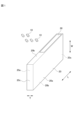
- FIG. 1 schematically shows a bulk case 20 as a first housing case and electronic components 10 housed in the bulk case 20 .
- a plurality of electronic components 10 are directly accommodated in the bulk case 20 .
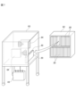
- FIG. 2 schematically shows an electronic component housing system according to the embodiment.
- the electronic component housing system according to the embodiment includes a bulk case 20 housing a plurality of electronic components 10 and an exterior box 81 as a second housing case housing a plurality of bulk cases 20 housing a plurality of electronic components 10. , an outer box for transportation 82 as a third housing case in which a plurality of outer boxes 81 are housed, and a pallet 83 as a fourth housing case in which a plurality of outer boxes for transportation 82 are housed.
- a plurality of bulk cases 20 are housed in an outer box 81, a plurality of outer boxes 81 housing a plurality of bulk cases 20 are housed in a single transport outer box 82, and a plurality of outer boxes 81 housing a plurality of outer boxes 81 are housed.
- An outer box 82 for transportation is stored in a state of being loaded on one pallet 83 .
- the electronic component 10 is a small rectangular parallelepiped electronic component with a length in the longitudinal direction of 1.2 mm or less, such as a multilayer ceramic capacitor or an inductor.
- the bulk case 20 is a thin rectangular parallelepiped box made of a rigid body such as resin.
- L indicates the length direction of the bulk case 20
- W indicates the width direction
- T indicates the thickness direction.
- the bulk case 20 has a pair of main surfaces 20a facing each other in the thickness (T) direction, a pair of first end faces 20b facing each other in the width (W) direction, and a pair of main surfaces 20b facing each other in the length (L) direction. and a second end face 20c.
- the bulk case 20 accommodates the bulk electronic components 10 in units of, for example, hundreds to tens of thousands. For example, a plurality of electronic components 10 are accommodated in the bulk case 20 through an openable and closable opening provided in one second end face 20c.
- the bulk case 20 includes a first RFID tag 30 having a planar shape.
- the first RFID tag 30 consists of an elongated adhesive seal.
- the first RFID tag 30 is attached to one end side of one first end surface 20 b of the bulk case 20 . That is, the first RFID tag 30 is arranged to face the first end surface 20b.
- the first RFID tag 30 includes a rectangular resin sheet 30a as a base material, an RFID chip 30b made of a semiconductor integrated circuit, and an external device for communication. , and a passive transponder having a plurality of antennas 30c.
- the RFID chip 30b and antenna 30c are attached to the sheet 30a.
- the first RFID tag 30 may be of a type in which the RFID chip 30b and the antenna 30c are embedded in the sheet 30a. Moreover, the type provided with a power supply part may be used.
- the RFID chip 30b includes a CPU, memory, communication circuit, and the like.
- the first RFID tag 30 can be rewritable (RO: Read Only), rewritable once (WORM: Wright Once Read Many), or rewritable (R/W: Read and Wright). can be used.
- RO Read Only
- WORM Wright Once Read Many
- R/W Read and Wright
- the first RFID tag 30 has a unique number.
- Information related to the electronic component 10 is input to the first RFID tag 30 .
- the information related to the electronic component 10 includes, for example, at least one of information related to the bulk case 20, production information including information related to the performance of the electronic component 10, and unique number information associated with the production information.
- the exterior box 81 accommodates a plurality of bulk cases 20.
- the exterior box 81 is a rectangular parallelepiped box made of a material having appropriate rigidity such as resin or cardboard.
- the exterior box 81 has a bottom plate portion 81a, four side plate portions 81b, and a top plate portion 81c.
- a plurality of bulk cases 20 are accommodated in the exterior box 81 by opening the top plate portion 81c that can be opened and closed.
- the plurality of bulk cases 20 are arranged such that the main surfaces 20a are aligned with each other and the width (W) direction is along the vertical direction, and the first RFID tag 30 arranged on the upper side is on the one direction side (the far side in FIG. 2).
- the first RFID tag 30 is arranged near the outer surface of the top plate portion 81c of the exterior box 81 .
- the first RFID tag 30 may be exposed to the outside.
- the exterior box 81 includes a second RFID tag 31 having a planar shape.
- the second RFID tag 31 is composed of a rectangular adhesive seal.
- the second RFID tag 31 has the same configuration as the first RFID tag 30 described above. That is, the second RFID tag 31 is a passive transponder in which an RFID chip and an antenna are provided on a base sheet made of resin.
- the second RFID tag 31 is attached to the upper portion of one side plate portion 81 b of the exterior box 81 on one side in the horizontal direction. That is, the second RFID tag 31 is arranged so as to face the surface of the side plate portion 81b.
- the plurality of bulk cases 20 are arranged such that the first RFID tag 30 is arranged on the opposite side of the second RFID tag 31 and the first RFID tag 30 and the second RFID tag 31 are appropriately spaced apart. preferably housed in the exterior box 81. Thereby, the second RFID tag 31 is arranged at a position not facing the first RFID tag 30 .
- the first RFID tag 30 and the second RFID tag 31 are preferably separated by at least 10 mm or more. Thereby, interference between the first RFID tag 30 and the second RFID tag 31 is suppressed.
- the second RFID tag 31 may be protected by covering the surface of the second RFID tag 31 with a seal.
- Information related to the electronic component 10 is input to the second RFID tag 31 .
- the information related to the electronic component 10 input to the second RFID tag 31 includes, for example, information related to the first RFID tag 30 and information related to the performance of the electronic component 10 input to the first RFID tag 30. At least one of production information and unique number information associated with the production information is included.
- the number of bulk cases 20 contained in the outer box 81 may be input to the second RFID tag 31 .
- the outer box 81 indicates which bulk case 20 is arranged and accommodated at which position in the outer box 81. location information may also be input to the second RFID tag 31 .
- the transport outer box 82 accommodates a plurality of outer boxes 81 in a two-tiered state.
- the transporting outer box 82 is a rectangular parallelepiped box made of a material having appropriate rigidity, such as resin or corrugated cardboard.
- the transportation outer box 82 has a bottom plate portion 81a, four side plate portions 81b, and a top plate portion 81c.
- a plurality of outer boxes 81 are accommodated in the outer box 82 for transportation by opening the top plate portion 81c that can be opened and closed.
- a plurality of exterior boxes 81 are accommodated in the transportation outer box 82 so that the second RFID tag 31 is arranged biased toward one direction (front side in FIG. 2).
- the second RFID tag 31 is arranged near the outer surface of the side plate portion 82b of the outer box 82 for transportation.
- the second RFID tag 31 may be exposed to the outside.
- the transportation outer box 82 includes a third RFID tag 32 having a planar shape.
- the third RFID tag 32 has the same configuration as the first RFID tag 30 and the second RFID tag 31 described above. That is, the third RFID tag 32 is a passive transponder in which an RFID chip and an antenna are provided on a base sheet made of resin.
- the third RFID tag 32 is affixed to the top of one side plate portion 82b of the transporting outer box 82 on the one end side. That is, the third RFID tag 32 is arranged so as to face the surface of the side plate portion 82b.
- the third RFID tag 32 is arranged at a position not facing the second RFID tag 31 and the first RFID tag 30 in order to suppress interference with the second RFID tag 31 and the first RFID tag 30. preferably.
- the third RFID tag 32 is preferably separated from the second RFID tag 31 by at least 10 mm.
- the third RFID tag 32 may be protected by covering the surface of the third RFID tag 32 with a seal.
- Information related to the electronic component 10 is input to the third RFID tag 32 .
- the information related to the electronic component 10 input to the third RFID tag 32 includes, for example, information about the first RFID tag 30, information about the second RFID tag 31, and information input to the first RFID tag 30. At least one of production information including information on the performance of the electronic component 10 and unique number information associated with the production information is included.
- the pallet 83 is a plate-shaped stand that is transported by a forklift 65, which will be described later.
- the pallet 83 is loaded with a plurality of transporting outer boxes 82 stacked in multiple stages on its upper surface 83a.
- a plurality of outer boxes for transportation 82 are loaded on a pallet 83 so that the third RFID tag 32 is biased toward one side (front side in FIG. 2).
- the third RFID tag 32 is preferably loaded on the pallet 83 so as to be exposed to the outside.
- the pallet 83 includes a fourth RFID tag 33 having a planar shape.
- the fourth RFID tag 33 has the same configuration as the first RFID tag 30, the second RFID tag 31 and the third RFID tag 32 described above. That is, the fourth RFID tag 33 is a passive transponder in which an RFID chip and an antenna are provided on a base resin sheet.
- a fourth RFID tag 33 is arranged at one end of one side 83 b of the pallet 83 . That is, the fourth RFID tag 33 is arranged so as to face the surface of the one side surface 83b.
- the fourth RFID tag 33 is placed between the third RFID tag 32 and the second RFID tag 31 . and the first RFID tag 30.
- the fourth RFID tag 33 is preferably separated from the third RFID tag 32 by at least 10 mm. The fourth RFID tag 33 may be protected by covering the surface of the fourth RFID tag 33 with a seal.
- Information related to the electronic component 10 is input to the fourth RFID tag 33 .
- the information related to the electronic component 10 input to the fourth RFID tag 33 includes information related to the first RFID tag 30, information related to the second RFID tag 31, information related to the third RFID tag 32, information related to the first RFID tag At least one of production information including performance information about the electronic component 10 input to the tag 30 and unique number information associated with the production information is included.
- FIG. 4 shows an example of the process up to the shipment of the manufactured electronic component 10 at the component manufacturer G that manufactures the electronic component 10 .
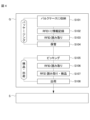
- FIG. 5 shows a hardware configuration for managing the electronic components 10 provided by the component manufacturer G. As shown in FIG.
- the parts manufacturer G has a writer unit 40 capable of writing information on the part manufacturer G side to the first RFID tag 30 provided in the bulk case 20, and the first RFID tag 30 provided in the bulk case 20. and a database server 44.
- the writer section 40 and the reader section 42 may be a reader/writer section in which both are integrated.
- the writer unit 40 includes a plurality of RFID writers 41 capable of writing information contactlessly. Each of the plurality of RFID writers 41 is arranged at a predetermined location in the parts manufacturer G's factory. The RFID writer 41 inputs the information read from the database server 44 by writing it to the first RFID tag 30 in a contactless manner.
- the reader unit 42 includes a plurality of RFID readers 43 capable of reading information contactlessly. Each of the plurality of RFID readers 43 is arranged at a predetermined location in the parts manufacturer G's factory. Information read by the RFID reader 43 is input to the database server 44 .
- the component manufacturer G performs packaging, inspection, and shipping processes for the electronic component 10 .
- a parts manufacturer G stores a large number of electronic parts 10 manufactured in a factory in a bulk case 20, transports and stores them, and ships them to a user S.
- the user S performs a process such as incorporating the received electronic component 10 into an electronic device set, for example.
- Electronic device sets include information terminal devices such as smartphones and tablets, and components such as electronic circuit boards that constitute such devices.
- a plurality of manufactured electronic components 10 are housed in a bulk case 20 (step S101).
- Information about the housed electronic components 10 is input to the first RFID tag 30 of the bulk case 20 housing the plurality of electronic components 10 by the predetermined RFID writer 41 (step S102).
- the information on the electronic component 10 in the embodiment includes the lot number of the electronic component 10, the quantity of the electronic component 10 housed in the bulk case 20, production information including information on the performance of the electronic component 10, electronic component 10 inspection number, bulk case 20 unique number, and so on.
- the information input to the first RFID tag 30 of one bulk case 20 is read by a predetermined RFID reader 43 .
- the unique number of the bulk case 20 is read (step S103).
- the information entered in the first RFID tag 30 is associated with the individual bulk case 20 and stored in the database server 44 .
- the bulk case 20 is picked from the storage location (step S105), and then the information recorded on the first RFID tag 30 is read (step S106).
- the bulk case 20 is picked from a storage location 62 such as a storage shelf and placed on a cart 63 for transportation. It is read by RFID reader 43 via sensor 64 .
- the RFID reader 43 is installed at an appropriate location on the cart 63 . Thereby, the fact that the bulk case 20 is to be shipped is input to the database server 44 .
- the information recorded in the first RFID tag 30 is read through the sensor 64 close to the bulk case 20 in this way. do it.
- the first RFID tag 30 of each bulk case 20 is read by the RFID reader 43, and the bulk case 20 is inspected (step S107).
- a predetermined number of the inspected bulk cases 20 are housed in one outer box 81, the plurality of outer boxes 81 are housed in one transport outer box 82, and a plurality of The transport outer box 82 is loaded on the pallet 83 and shipped to the user S (step S108).
- the pallet 83 is transported to a transportation means such as a truck by a forklift 65 as shown in FIG. 8 and loaded.
- a transportation means such as a truck by a forklift 65 as shown in FIG. 8 and loaded.
- the RFID reader 43 reads the fourth RFID tag 33 via the sensor 64 arranged at the gate 66 .
- the fourth RFID tag 33 By reading the fourth RFID tag 33, information input to each of the plurality of third RFID tags 32 input to the fourth RFID tag 33 is read. In other words, the information input to each of the second RFID tag 31 and the first RFID tag 30 is read. By arranging the fourth RFID tag 33 at a position not facing the third RFID tag 32, the RFID reader 43 can read only the fourth RFID tag 33 without interfering with the third RFID tag 32. .
- Information about the bulk case 20 and the electronic components 10 housed in the bulk case 20 includes, for example, the lot number of the electronic components 10, the quantity of the electronic components 10 housed in the bulk case 20, and the electronic components 10, as described above. production information including information on the performance of the electronic component 10, the inspection number of the electronic component 10, the unique number of the bulk case 20, and the like.
- the fourth RFID tag 33 by reading the fourth RFID tag 33 at the time of shipment, information is sequentially obtained from the third RFID tag 32, the second RFID tag 31, and the first RFID tag 30, and finally the electronic component 10 is obtained. and information about the bulk case 20.
- the fourth RFID tag 33 and reading the third RFID tag 32 of the outer shipping box 82 the information input to the first RFID tag 30 and the second RFID tag 31 is read, Management may be performed based on that information.
- the information input to the first RFID tag 30 is read, and the information may be managed based on In either case, since the information to be read is the information of the first RFID tag 30, it is the same information.
- FIG. 9 shows an example of a form of reading the second RFID tag 31 of the exterior box 81.
- the RFID reader 43 reads the second RFID tag 31 through the sensor 64 provided in the gate 68 while the outer box 81 being conveyed by the conveyor 67 is conveyed in the tunnel-shaped gate 68. there is Thereby, the first RFID tags 30 of the plurality of bulk cases 20 of the outer box 81 can be read.
- the plurality of outer transport boxes 82 are loaded on the pallet 83.
- Information about the electronic component 10 and the bulk case 20 is input to each of the second RFID tag 31, the third RFID tag 32, and the fourth RFID tag 33 at each timing.
- information is input to the fourth RFID tag 33 by loading a plurality of outer boxes 82 for transportation on the pallet 83.
- information is input to all the second RFID tags 31 and the third RFID tags 32. good too.
- information can be input to all of the second RFID tags 31 and the third RFID tags 32 by one information input operation, which greatly saves time and effort.
- information about the electronic component 10 and the bulk case 20 is input to all of the second RFID tag 31, the third RFID tag 32, and the fourth RFID tag 33. Only the unique number associated with the bulk case 20 may be entered in the tag 31 , the third RFID tag 32 and the fourth RFID tag 33 . In that case, when the second RFID tag 31, the third RFID tag 32 and the fourth RFID tag 33 are read, information on the electronic component 10 and the bulk case 20 is obtained based on the unique number of the first RFID tag 30. It may be made readable.
- the database server 44 all the information about the electronic parts 10 and the bulk case 20 is input to the database server 44 and stored, and only the unique numbers associated with the information are sent to the first RFID tag 30 and the second RFID tag 31. , the third RFID tag 32 and the fourth RFID tag 33 can also be written. In this case, when the predetermined RFID reader 43 reads any one of the first RFID tag 30, the second RFID tag 31, the third RFID tag 32 and the fourth RFID tag 33, the database server 44 is accessed. , reads the information stored in the database server 44 associated with the unique number.
- the electronic component accommodation system includes a bulk case 20 as a first accommodation case that accommodates the electronic component 10 and has a first RFID tag 30 to which information related to the electronic component 10 is input, and a bulk case 20 and an outer box 81 as a second housing case having a second RFID tag 31 into which information related to the electronic component 10 is input.
- the information related to the electronic component 10 input to the first RFID tag 30 includes information related to the bulk case 20, production information including information related to the performance of the electronic component 10, and production information. unique number information associated with the .
- the information related to the electronic component 10 input to the second RFID tag 31 includes the information related to the first RFID tag 30 and the electronic component input to the first RFID tag 30 . It is preferable to include at least one of production information including information on the performance of the part 10 and unique number information associated with the production information.
- the first RFID tag 30 is arranged to face the first end surface 20b of the bulk case 20, and the bulk case 20 has the first RFID tag 30 as an exterior.
- the second RFID tag 31 is arranged near the outer surface of the box 81 or is arranged inside the exterior box 81 so as to be exposed to the outside, and the second RFID tag 31 is arranged at a position not facing the first RFID tag 30. preferably.
- the communication distance when reading from and writing to the first RFID tag 30 can be shortened as much as possible, and interference between RFID tags is less likely to occur, so stable communication can be performed.
- the electronic component storage system by reading the second RFID tag 31 with the reader unit 42 as a reading unit, information input to the first RFID tag 30 and information related to the electronic component 10 is preferably read.
- a plurality of outer boxes 81 are accommodated, and an outer transport box 82 as a third storage case having a third RFID tag 32 into which information related to the electronic component 10 is input. is preferably further provided.
- the information related to the electronic component 10 input to the third RFID tag 32 includes information related to the first RFID tag 30, information related to the second RFID tag 31, information related to the first It is preferable that at least one of production information including information about the performance of the electronic component 10 input to the RFID tag 30 and unique number information associated with the production information is included.
- the third RFID tag 32 information on the first RFID tag 30, information on the second RFID tag 31, and information on the performance of the electronic component 10 input to the first RFID tag 30 can be obtained. At least one of the production information included and the unique number information associated with the production information can be managed for each outer shipping box 82 .
- the second RFID tag 31 is arranged so as to face the surface of the side plate portion 81b of the outer box 81, and the outer box 81 has the second RFID tag 31
- the third RFID tag 32 is arranged in the vicinity of the outer surface of the outer shipping box 82 or in the outer shipping box 82 so as to be exposed to the outside. It is preferable that it is arranged at a position not facing any of the two RFID tags 31 .
- the communication distance when reading from and writing to the second RFID tag 31 can be shortened as much as possible, and interference between RFID tags is less likely to occur, so stable communication can be performed.
- the electronic component storage system by reading the third RFID tag 32 with the reader unit 42, information input to the first RFID tag 30, information input to the second RFID tag 31, and preferably read information related to the electronic component 10 .
- a pallet 83 as a fourth storage case containing a plurality of outer boxes for transportation 82 and having a fourth RFID tag 33 into which information related to the electronic component 10 is input is provided. Further, it is preferable to have.
- the information related to the electronic component 10 input to the fourth RFID tag 33 includes information related to the first RFID tag 30, information related to the second RFID tag 31, information related to the third information on the first RFID tag 32, production information including performance information on the electronic component 10 input to the first RFID tag 30, and unique number information associated with the production information.
- At least one of production information including information on the performance of the electronic component 10 that is stored in the pallet 83 and unique number information associated with the production information can be managed for each pallet 83 .
- the third RFID tag 32 is arranged so as to face the surface of the side plate portion 82b of the outer transporting box 82, and the outer transporting box 82
- the RFID tag 32 is placed near the outer surface of the pallet 83 or is placed on the pallet 83 so as to be exposed to the outside. It is preferable that it is arranged at a position facing neither the tag 31 nor the third RFID tag 32 .
- the communication distance when reading from and writing to the third RFID tag 32 can be shortened as much as possible, and interference between RFID tags is less likely to occur, so stable communication can be performed.
- the electronic component storage system by reading the fourth RFID tag 33 with the reader unit 42, information input to the first RFID tag 30, information input to the second RFID tag 31, Preferably, the information entered into the third RFID tag 32 and information associated with the electronic component 10 is read.
Landscapes
- Engineering & Computer Science (AREA)
- Physics & Mathematics (AREA)
- Microelectronics & Electronic Packaging (AREA)
- Theoretical Computer Science (AREA)
- Computer Networks & Wireless Communication (AREA)
- General Physics & Mathematics (AREA)
- Toxicology (AREA)
- Health & Medical Sciences (AREA)
- Manufacturing & Machinery (AREA)
- Computer Hardware Design (AREA)
- Electromagnetism (AREA)
- General Health & Medical Sciences (AREA)
- Artificial Intelligence (AREA)
- Computer Vision & Pattern Recognition (AREA)
- Mechanical Engineering (AREA)
- General Engineering & Computer Science (AREA)
- Computer Security & Cryptography (AREA)
- Signal Processing (AREA)
- Operations Research (AREA)
- Supply And Installment Of Electrical Components (AREA)
- General Factory Administration (AREA)
Abstract
Description
図1は、第1の収容ケースとしてのバルクケース20、及びバルクケース20に収容される電子部品10を概略的に示している。バルクケース20には、複数の電子部品10が直接収容される。
以下、図4を参照して、部品メーカーG及びセットメーカーSでの電子部品10の流れを説明する。
実施形態に係る電子部品収容システムは、電子部品10が収容され、電子部品10に関連する情報が入力される第1のRFIDタグ30を有する第1の収容ケースとしてのバルクケース20と、バルクケース20が複数収容され、電子部品10に関連する情報が入力される第2のRFIDタグ31を有する第2の収容ケースとしての外装箱81と、を備える。
20 バルクケース(第1の収容ケース)
30 第1のRFIDタグ
31 第2のRFIDタグ
32 第3のRFIDタグ
33 第4のRFIDタグ
42 リーダー部(読み取り部)
81 外装箱(第2の収容ケース)
82 運搬用外箱(第3の収容ケース)
83 パレット(第4の収容ケース)
Claims (13)
- 電子部品が収容され、前記電子部品に関連する情報が入力される第1のRFIDタグを有する第1の収容ケースと、
前記第1の収容ケースが複数収容され、前記電子部品に関連する情報が入力される第2のRFIDタグを有する第2の収容ケースと、を備える電子部品収容システム。 - 前記第1のRFIDタグに入力される前記電子部品に関連する情報は、前記第1の収容ケースに関する情報、前記電子部品の性能に関する情報を含む生産情報、前記生産情報と関連付けられる固有番号情報、のうちの少なくとも1つを含む、請求項1に記載の電子部品収容システム。
- 前記第2のRFIDタグに入力される前記電子部品に関連する情報は、前記第1のRFIDタグに関する情報、前記第1のRFIDタグに入力される前記電子部品の性能に関する情報を含む生産情報、前記生産情報と関連付けられる固有番号情報、のうちの少なくとも1つを含む、請求項1または2に記載の電子部品収容システム。
- 前記第1のRFIDタグは、前記第1の収容ケースが備えるいずれかの面に対向するように配置されており、
前記第1の収容ケースは、前記第1のRFIDタグが前記第2の収容ケースの外表面近傍に配置されるか、もしくは外部に露出するように前記第2の収容ケース内に配置されており、
前記第2のRFIDタグは、前記第1のRFIDタグに対向しない位置に配置されている、請求項1~3のいずれか1項に記載の電子部品収容システム。 - 前記第2のRFIDタグを読み取り部で読み取ることで、前記第1のRFIDタグに入力される情報、及び前記電子部品に関連する情報を読み取る、請求項1~4のいずれか1項に記載の電子部品収容システム。
- 前記第2の収容ケースが複数収容され、前記電子部品に関連する情報が入力される第3のRFIDタグを有する第3の収容ケースをさらに備える、請求項1~5のいずれか1項に記載の電子部品収容システム。
- 前記第3のRFIDタグに入力される前記電子部品に関連する情報は、前記第1のRFIDタグに関する情報、前記第2のRFIDタグに関する情報、前記第1のRFIDタグに入力される前記電子部品の性能に関する情報を含む生産情報、前記生産情報と関連付けられる固有番号情報、のうちの少なくとも1つを含む、請求項6に記載の電子部品収容システム。
- 前記第2のRFIDタグは、前記第2の収容ケースが備えるいずれかの面に対向するように配置されており、
前記第2の収容ケースは、前記第2のRFIDタグが前記第3の収容ケースの外表面近傍に配置されるか、もしくは外部に露出するように前記第3の収容ケース内に配置されており、
前記第3のRFIDタグは、前記第1のRFIDタグ及び前記第2のRFIDタグのいずれにも対向しない位置に配置されている、請求項6または7に記載の電子部品収容システム。 - 前記第3のRFIDタグを読み取り部で読み取ることで、前記第1のRFIDタグに入力される情報、前記第2のRFIDタグに入力される情報、及び前記電子部品に関連する情報を読み取る、請求項6~8のいずれか1項に記載の電子部品収容システム。
- 前記第3の収容ケースが複数収容され、前記電子部品に関連する情報が入力される第4のRFIDタグを有する第4の収容ケースをさらに備える、請求項6~9のいずれか1項に記載の電子部品収容システム。
- 前記第4のRFIDタグに入力される前記電子部品に関連する情報は、前記第1のRFIDタグに関する情報、前記第2のRFIDタグに関する情報、前記第3のRFIDタグに関する情報、前記第1のRFIDタグに入力される前記電子部品に関する性能情報を含む生産情報、前記生産情報と関連付けられる固有番号情報、のうちの少なくとも1つを含む、請求項10に記載の電子部品収容システム。
- 前記第3のRFIDタグは、前記第3の収容ケースが備えるいずれかの面に対向する位置に配置されており、
前記第3の収容ケースは、前記第3のRFIDタグが前記第4の収容ケースの外表面近傍に配置されるか、もしくは外部に露出するように前記第4の収容ケース内に配置されており、
前記第4のRFIDタグは、前記第1のRFIDタグ、前記第2のRFIDタグ及び前記第3のRFIDタグのいずれにも対向しない位置に配置されている、請求項10または11に記載の電子部品収容システム。 - 前記第4のRFIDタグを読み取り部で読み取ることで、前記第1のRFIDタグに入力される情報、前記第2のRFIDタグに入力される情報、前記第3のRFIDタグに入力される情報、及び前記電子部品に関連する情報を読み取る、請求項10~12のいずれか1項に記載の電子部品収容システム。
Priority Applications (4)
| Application Number | Priority Date | Filing Date | Title |
|---|---|---|---|
| JP2023538298A JPWO2023007924A1 (ja) | 2021-07-29 | 2022-05-23 | |
| CN202280046367.XA CN117580786A (zh) | 2021-07-29 | 2022-05-23 | 电子部件容纳系统 |
| KR1020247002072A KR20240023153A (ko) | 2021-07-29 | 2022-05-23 | 전자부품 수용 시스템 |
| US18/423,964 US20240164079A1 (en) | 2021-07-29 | 2024-01-26 | Electronic component accommodation system |
Applications Claiming Priority (2)
| Application Number | Priority Date | Filing Date | Title |
|---|---|---|---|
| JP2021-124486 | 2021-07-29 | ||
| JP2021124486 | 2021-07-29 |
Related Child Applications (1)
| Application Number | Title | Priority Date | Filing Date |
|---|---|---|---|
| US18/423,964 Continuation US20240164079A1 (en) | 2021-07-29 | 2024-01-26 | Electronic component accommodation system |
Publications (1)
| Publication Number | Publication Date |
|---|---|
| WO2023007924A1 true WO2023007924A1 (ja) | 2023-02-02 |
Family
ID=85086506
Family Applications (1)
| Application Number | Title | Priority Date | Filing Date |
|---|---|---|---|
| PCT/JP2022/021113 WO2023007924A1 (ja) | 2021-07-29 | 2022-05-23 | 電子部品収容システム |
Country Status (5)
| Country | Link |
|---|---|
| US (1) | US20240164079A1 (ja) |
| JP (1) | JPWO2023007924A1 (ja) |
| KR (1) | KR20240023153A (ja) |
| CN (1) | CN117580786A (ja) |
| WO (1) | WO2023007924A1 (ja) |
Citations (7)
| Publication number | Priority date | Publication date | Assignee | Title |
|---|---|---|---|---|
| JP2005032899A (ja) * | 2003-07-10 | 2005-02-03 | Fuji Mach Mfg Co Ltd | 部品供給テープ接続部材,接続部材供給装置,電子回路部品供給システム,電子回路部品装着システム,部品情報付与方法および電子回路部品供給方法 |
| JP2005101576A (ja) * | 2003-08-26 | 2005-04-14 | Matsushita Electric Ind Co Ltd | 部品照合方法 |
| WO2005115290A1 (ja) * | 2004-05-25 | 2005-12-08 | Livedo Corporation | おむつ製品、供給情報管理システム、使用情報管理システムおよびおむつ製品管理システム |
| JP2006027773A (ja) * | 2004-07-13 | 2006-02-02 | Ntn Corp | Icタグ利用検品システム |
| WO2007125710A1 (ja) * | 2006-04-28 | 2007-11-08 | Kazunori Fujisawa | 物流用容器及び梱包容器 |
| JP2009295618A (ja) * | 2008-06-02 | 2009-12-17 | Taiyo Yuden Co Ltd | バルクフィーダ用の部品補充システム |
| JP2022040553A (ja) * | 2020-08-31 | 2022-03-11 | パナソニックIpマネジメント株式会社 | フィーダ、収容体、及び、実装システム |
Family Cites Families (2)
| Publication number | Priority date | Publication date | Assignee | Title |
|---|---|---|---|---|
| JP2002358494A (ja) | 2001-06-01 | 2002-12-13 | Hitachi Kokusai Electric Inc | 移動体識別用無線タグ |
| JP4134947B2 (ja) | 2004-05-17 | 2008-08-20 | 株式会社村田製作所 | 電子部品の出荷方法 |
-
2022
- 2022-05-23 CN CN202280046367.XA patent/CN117580786A/zh active Pending
- 2022-05-23 KR KR1020247002072A patent/KR20240023153A/ko unknown
- 2022-05-23 JP JP2023538298A patent/JPWO2023007924A1/ja active Pending
- 2022-05-23 WO PCT/JP2022/021113 patent/WO2023007924A1/ja active Application Filing
-
2024
- 2024-01-26 US US18/423,964 patent/US20240164079A1/en active Pending
Patent Citations (7)
| Publication number | Priority date | Publication date | Assignee | Title |
|---|---|---|---|---|
| JP2005032899A (ja) * | 2003-07-10 | 2005-02-03 | Fuji Mach Mfg Co Ltd | 部品供給テープ接続部材,接続部材供給装置,電子回路部品供給システム,電子回路部品装着システム,部品情報付与方法および電子回路部品供給方法 |
| JP2005101576A (ja) * | 2003-08-26 | 2005-04-14 | Matsushita Electric Ind Co Ltd | 部品照合方法 |
| WO2005115290A1 (ja) * | 2004-05-25 | 2005-12-08 | Livedo Corporation | おむつ製品、供給情報管理システム、使用情報管理システムおよびおむつ製品管理システム |
| JP2006027773A (ja) * | 2004-07-13 | 2006-02-02 | Ntn Corp | Icタグ利用検品システム |
| WO2007125710A1 (ja) * | 2006-04-28 | 2007-11-08 | Kazunori Fujisawa | 物流用容器及び梱包容器 |
| JP2009295618A (ja) * | 2008-06-02 | 2009-12-17 | Taiyo Yuden Co Ltd | バルクフィーダ用の部品補充システム |
| JP2022040553A (ja) * | 2020-08-31 | 2022-03-11 | パナソニックIpマネジメント株式会社 | フィーダ、収容体、及び、実装システム |
Also Published As
| Publication number | Publication date |
|---|---|
| JPWO2023007924A1 (ja) | 2023-02-02 |
| US20240164079A1 (en) | 2024-05-16 |
| CN117580786A (zh) | 2024-02-20 |
| KR20240023153A (ko) | 2024-02-20 |
Similar Documents
| Publication | Publication Date | Title |
|---|---|---|
| JP4742546B2 (ja) | 物品搬送資材 | |
| EP1635290B1 (en) | Physical distribution management apparatus, physical distribution management pallet and physical distribution management system | |
| JP2006076644A5 (ja) | ||
| KR101156580B1 (ko) | 자동 물류처리 시스템 및 방법 | |
| CN111556847B (zh) | 保管装置以及保管方法 | |
| JP4552574B2 (ja) | 物品搬送資材、及び物流管理システム | |
| US20240086673A1 (en) | Electronic component management method, and housing body for electronic components | |
| JP6045165B2 (ja) | 物品の物流方法 | |
| WO2023007924A1 (ja) | 電子部品収容システム | |
| JP2006240868A (ja) | 製品物流管理システム | |
| TWI701207B (zh) | 智慧棧板 | |
| JP5061495B2 (ja) | 検品装置 | |
| WO2022244438A1 (ja) | 電子部品の管理方法 | |
| WO2023074159A1 (ja) | 電子部品の管理方法 | |
| JP6217139B2 (ja) | 基板収納用梱包体及び基板収納用梱包体の管理方法 | |
| JP5360809B2 (ja) | 運搬用容器 | |
| TWI784429B (zh) | 晶粒儲料器、儲存晶粒載體的方法以及半導體晶粒製造系統 | |
| WO2024095749A1 (ja) | 電子部品収納体及び電子部品収納体梱包体 | |
| US20240128105A1 (en) | Cover for module tray and module tray for semiconductor device including the same | |
| WO2024090266A1 (ja) | 電子部品収納体及び電子部品収納体梱包体 | |
| KR20220086845A (ko) | 스마트 물류관리 시스템 | |
| JPWO2007125710A1 (ja) | 物流用容器及び梱包容器 | |
| CA2321009A1 (en) | Automated manufacturing control system | |
| CA2326301A1 (en) | Automated manufacturing control system | |
| JP2006027774A (ja) | 梱包重量管理システム |
Legal Events
| Date | Code | Title | Description |
|---|---|---|---|
| 121 | Ep: the epo has been informed by wipo that ep was designated in this application |
Ref document number: 22849003 Country of ref document: EP Kind code of ref document: A1 |
|
| WWE | Wipo information: entry into national phase |
Ref document number: 202280046367.X Country of ref document: CN |
|
| WWE | Wipo information: entry into national phase |
Ref document number: 2023538298 Country of ref document: JP |
|
| ENP | Entry into the national phase |
Ref document number: 20247002072 Country of ref document: KR Kind code of ref document: A |
|
| WWE | Wipo information: entry into national phase |
Ref document number: 1020247002072 Country of ref document: KR |
|
| NENP | Non-entry into the national phase |
Ref country code: DE |
|
| 122 | Ep: pct application non-entry in european phase |
Ref document number: 22849003 Country of ref document: EP Kind code of ref document: A1 |