WO2023007541A1 - ワイピング装置及び圧延設備 - Google Patents
ワイピング装置及び圧延設備 Download PDFInfo
- Publication number
- WO2023007541A1 WO2023007541A1 PCT/JP2021/027515 JP2021027515W WO2023007541A1 WO 2023007541 A1 WO2023007541 A1 WO 2023007541A1 JP 2021027515 W JP2021027515 W JP 2021027515W WO 2023007541 A1 WO2023007541 A1 WO 2023007541A1
- Authority
- WO
- WIPO (PCT)
- Prior art keywords
- strip
- wiping member
- wiping
- width direction
- plate
- Prior art date
Links
- 238000005096 rolling process Methods 0.000 title claims abstract description 77
- 239000007788 liquid Substances 0.000 claims abstract description 48
- 239000002184 metal Substances 0.000 claims abstract description 18
- 238000011144 upstream manufacturing Methods 0.000 claims description 35
- 239000002826 coolant Substances 0.000 description 18
- OKTJSMMVPCPJKN-UHFFFAOYSA-N Carbon Chemical compound [C] OKTJSMMVPCPJKN-UHFFFAOYSA-N 0.000 description 16
- 229910002804 graphite Inorganic materials 0.000 description 16
- 239000010439 graphite Substances 0.000 description 16
- 238000005299 abrasion Methods 0.000 description 14
- 239000000835 fiber Substances 0.000 description 13
- 239000000463 material Substances 0.000 description 11
- 239000000805 composite resin Substances 0.000 description 10
- 229920001721 polyimide Polymers 0.000 description 6
- 239000000843 powder Substances 0.000 description 6
- 230000014509 gene expression Effects 0.000 description 5
- 238000004804 winding Methods 0.000 description 5
- 239000007787 solid Substances 0.000 description 4
- 239000000126 substance Substances 0.000 description 4
- 239000004642 Polyimide Substances 0.000 description 3
- 239000002131 composite material Substances 0.000 description 3
- 239000003733 fiber-reinforced composite Substances 0.000 description 3
- 239000007769 metal material Substances 0.000 description 3
- 239000009719 polyimide resin Substances 0.000 description 3
- 238000010586 diagram Methods 0.000 description 2
- 238000012423 maintenance Methods 0.000 description 2
- 230000002093 peripheral effect Effects 0.000 description 2
- 229910000831 Steel Inorganic materials 0.000 description 1
- 230000000694 effects Effects 0.000 description 1
- 238000000034 method Methods 0.000 description 1
- 238000012986 modification Methods 0.000 description 1
- 230000004048 modification Effects 0.000 description 1
- 239000010959 steel Substances 0.000 description 1
Images


Classifications
-
- B—PERFORMING OPERATIONS; TRANSPORTING
- B21—MECHANICAL METAL-WORKING WITHOUT ESSENTIALLY REMOVING MATERIAL; PUNCHING METAL
- B21B—ROLLING OF METAL
- B21B45/00—Devices for surface or other treatment of work, specially combined with or arranged in, or specially adapted for use in connection with, metal-rolling mills
- B21B45/02—Devices for surface or other treatment of work, specially combined with or arranged in, or specially adapted for use in connection with, metal-rolling mills for lubricating, cooling, or cleaning
- B21B45/0269—Cleaning
- B21B45/0275—Cleaning devices
- B21B45/0278—Cleaning devices removing liquids
- B21B45/0281—Cleaning devices removing liquids removing coolants
-
- B—PERFORMING OPERATIONS; TRANSPORTING
- B21—MECHANICAL METAL-WORKING WITHOUT ESSENTIALLY REMOVING MATERIAL; PUNCHING METAL
- B21B—ROLLING OF METAL
- B21B1/00—Metal-rolling methods or mills for making semi-finished products of solid or profiled cross-section; Sequence of operations in milling trains; Layout of rolling-mill plant, e.g. grouping of stands; Succession of passes or of sectional pass alternations
- B21B1/22—Metal-rolling methods or mills for making semi-finished products of solid or profiled cross-section; Sequence of operations in milling trains; Layout of rolling-mill plant, e.g. grouping of stands; Succession of passes or of sectional pass alternations for rolling plates, strips, bands or sheets of indefinite length
- B21B1/24—Metal-rolling methods or mills for making semi-finished products of solid or profiled cross-section; Sequence of operations in milling trains; Layout of rolling-mill plant, e.g. grouping of stands; Succession of passes or of sectional pass alternations for rolling plates, strips, bands or sheets of indefinite length in a continuous or semi-continuous process
-
- B—PERFORMING OPERATIONS; TRANSPORTING
- B08—CLEANING
- B08B—CLEANING IN GENERAL; PREVENTION OF FOULING IN GENERAL
- B08B1/00—Cleaning by methods involving the use of tools
- B08B1/10—Cleaning by methods involving the use of tools characterised by the type of cleaning tool
- B08B1/16—Rigid blades, e.g. scrapers; Flexible blades, e.g. wipers
-
- B—PERFORMING OPERATIONS; TRANSPORTING
- B08—CLEANING
- B08B—CLEANING IN GENERAL; PREVENTION OF FOULING IN GENERAL
- B08B1/00—Cleaning by methods involving the use of tools
- B08B1/20—Cleaning of moving articles, e.g. of moving webs or of objects on a conveyor
-
- B—PERFORMING OPERATIONS; TRANSPORTING
- B21—MECHANICAL METAL-WORKING WITHOUT ESSENTIALLY REMOVING MATERIAL; PUNCHING METAL
- B21B—ROLLING OF METAL
- B21B45/00—Devices for surface or other treatment of work, specially combined with or arranged in, or specially adapted for use in connection with, metal-rolling mills
- B21B45/02—Devices for surface or other treatment of work, specially combined with or arranged in, or specially adapted for use in connection with, metal-rolling mills for lubricating, cooling, or cleaning
- B21B45/0269—Cleaning
- B21B45/0275—Cleaning devices
- B21B45/0278—Cleaning devices removing liquids
Definitions
- the present disclosure relates to wiping devices and rolling equipment.
- Patent Documents 1 and 2 respectively, on the downstream side of a rolling roll for rolling a metal strip, it is provided so as to extend in a direction perpendicular to the conveying direction of the strip and contact the surface of the strip A wiping device is described that includes a stationary (contact) wiper.
- stationary (contact-type) wipers are less likely to scatter liquid such as coolant removed from the surface of the strip by the wiper, or the contact between the wiper and the strip is greater than the width of the strip. Since it tends to be uniform in the direction, there is an advantage that unevenness in wiping is less likely to occur.
- liquid such as coolant removed from the surface of the strip by the wiper tends to stay upstream of the wiper. If the coolant contains foreign matter such as metal powder caused by wear of the rolling rolls and strips, and wear debris caused by wiper wear, these foreign substances will also stay upstream of the wiper and form lumps. become. The surface of the strip may be damaged by such accumulated foreign matter.
- a wiping device comprises: A wiping device for removing liquid from the surface of a conveyed metal strip, comprising: A first wiping member provided so as to be in contact with the rolled surface of the strip, The first wiping member has an inclined portion extending in a direction inclined with respect to the width direction of the strip.
- the rolling equipment is rolling rolls for rolling the strip of metal; the above-described wiping device provided downstream of the rolling rolls in the conveying direction of the strip; Prepare.
- a wiping device and a rolling facility that do not easily damage the surface of the metal strip.
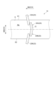
- FIG. 1 is a schematic diagram of a rolling facility equipped with a wiping device according to one embodiment
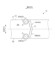
- FIG. FIG. 2 is a schematic plan view of a wiping device in the rolling facility shown in FIG. 1
- FIG. 2 is a schematic cross-sectional view of a first wiping member in the rolling facility shown in FIG. 1
- It is a schematic sectional drawing of the 1st wiping member in the rolling equipment which concerns on one Embodiment.
- 1 is a schematic plan view of a wiping device according to one embodiment
- FIG. 1 is a schematic plan view of a wiping device according to one embodiment
- FIG. 1 is a schematic plan view of a wiping device according to one embodiment
- FIG. 1 is a schematic plan view of a wiping device according to one embodiment
- FIG. 1 is a schematic plan view of a wiping device according to one embodiment
- FIG. 1 is a schematic plan view of a wiping device according to one embodiment
- FIG. 1 is a schematic plan view of a wiping device
- FIG. 1 is a schematic plan view of a wiping device according to one embodiment;
- FIG. It is a schematic sectional view of the side wiper of the wiping device which concerns on one Embodiment. It is a schematic sectional view of the side wiper of the wiping device which concerns on one Embodiment.
- FIG. 1 is a schematic diagram of a rolling facility equipped with a wiping device according to some embodiments.
- 2 is a schematic plan view of a wiping device in the rolling facility shown in FIG. 1.
- FIG. 5 to 9 are schematic plan views of the wiping device 10 according to one embodiment.
- a rolling facility 1 includes a rolling mill 4 including rolling rolls 2 for rolling a metal (steel or the like) strip S, and rolling in the transport direction of the strip S. and a wiping device 10 provided downstream of the roll 2 .
- the rolling facility 1 may include a winding device 8 for winding the strip S rolled by the rolling rolls 2 , provided between the rolling rolls 2 and the winding device 8 . and guide rolls 6 for guiding the strip S to the rolling rolls 2 may be provided.
- the wiping device 10 may be provided between the rolling rolls 2 and the winding device 8 in the conveying direction of the strip S.
- the wiping device 10 is a wiping device for removing liquid such as coolant from the surface of the strip S by wiping.
- the wiping device 10 includes a first wiping member 12 that is provided so as to be in contact with the surface of the strip S.
- FIG. 3 is a schematic cross-sectional view of the first wiping member 12 in the rolling facility 1 shown in FIG.
- the first wiping member 12 is provided so as to be in contact with the rolling surface Sa or Sb of the strip S.
- the wiping device 10 includes first wiping members 12, 12 capable of contacting an upper rolling surface Sa and a lower rolling surface Sb of the strip S, respectively.
- each first wiping member 12 has a flat surface 14 that can contact the rolling surface Sa or Sb.
- the rolled surfaces Sa and Sb of the strip S are the surfaces of the strip S that are rolled by the rolling rolls 2 or rolled by the rolling rolls 2 (surfaces in contact with the outer peripheral surfaces of the rolling rolls 2). means.
- the first wiping member 12 has an inclined portion 20 extending in a direction inclined with respect to the width direction of the strip S. As shown in FIG. In the exemplary embodiment shown in FIG. 2, the entire first wiping member 12 is an inclined portion 20 extending in a direction inclined with respect to the width direction of the strip S. As shown in FIG. In the exemplary embodiment shown in FIGS. 5 to 9, the first wiping member 12 has a first inclined portion 20A (inclined portion 20) and a second inclined portion 20B (inclined portion 20) that extend in different directions. include.
- the wiping device 10 may include a pressing portion configured to press the first wiping member 12 toward the rolling surfaces Sa and Sb of the strip S.
- the flat surface 14 of the first wiping member 12 can be brought into contact with the surface of the strip S by pressing the first wiping member 12 against the strip S by the pressing portion.
- the pressing portion may include, for example, a hydraulic cylinder or pneumatic cylinder, or an elastic member such as a spring.
- the wiping device 10 may include a holding member 24 that holds the first wiping member 12. As shown in FIG. The pressing portion described above may apply pressing forces (forces for pressing the first wiping member 12 against the strip S) F1 and F2 to the first wiping member 12 via the holding member 24 .
- liquid such as coolant removed from the surface of the strip by the wiper tends to stay upstream of the wiper. If the coolant contains foreign matter such as metal powder caused by abrasion of the rolling rolls and strips, and abrasion scum caused by abrasion of the wiper, these foreign matter also stay upstream of the wiper. In some cases, the surface of the strip may be damaged by foreign matter remaining thereon.
- the first wiping member 12 has the inclined portion 20 extending in a direction inclined with respect to the width direction of the strip, so that the first wiping member 12 removes the strip S from the surface.
- Liquid and foreign matter contained in the liquid are less likely to stay upstream of the first wiping member 12 and are more likely to be discharged laterally of the strip S along the inclined portion 20 of the first wiping member 12 . Therefore, according to the above-described embodiment, the discharge of foreign matter contained in the liquid (solid matter mixed in the coolant (metal powder, etc. generated by abrasion of the rolling rolls and strips, abrasion debris of the wiping member, etc.)) is promoted. can do. Therefore, it is possible to effectively prevent the surface of the strip S from being scratched due to the foreign matter remaining on the upstream side of the first wiping member 12 .
- the direction in which the inclined portions 20, 20A, and 20B of the first wiping member 12 extend (indicated by straight lines L1, L1A, and L1B in FIGS.
- the inclination angles ⁇ 1, ⁇ 1A, ⁇ 1B (see FIGS. 2 and 5 to 9) with respect to the straight line L0 in FIGS. 5 to 9) may be, for example, 1 degree or more and 45 degrees or less, more preferably 3 degree or more and 10 degrees or less. Since the above-described inclination angle is 1 degree or more or 3 degrees or more, the liquid remaining on the upstream side of the first wiping member 12 is effectively directed laterally along the first wiping member 12 in the plate width direction. can be discharged. In addition, since the above-mentioned inclination angle is 45 degrees or less or 10 degrees or less, the length of the first wiping member 12 is unlikely to be excessively large, so the wiping device 10 can be prevented from becoming large.
- the first wiping member 12 may extend from the first end E1 to the second end E2 in the width direction of the strip S (see FIGS. 2, 5, and 5). 8). Alternatively, in some embodiments, the first wiping member 12 extends between the first end E1 and the second end E2 of the strip S in the width direction of the strip S. (that is, the end portion of the first wiping member 12 in the plate width direction may not reach the plate end (first end E1 or second end E2) of the strip S) (FIGS. 6 and 7 and FIG. 9).
- the first wiping member 12 may be made of a graphite fiber reinforced resin composite material.
- the graphite fiber reinforced resin composite material may include, for example, a graphite fiber reinforced polyimide resin composite (PGFC: polyimide graphite fiber reinforced composite).
- Graphite fiber reinforced resin composite materials such as PGFC have self-lubricating properties and have a small coefficient of friction with metal materials. Therefore, since the first wiping member 12 is made of the graphite fiber reinforced resin composite material, heat and wear due to friction between the first wiping member 12 and the strip S are less likely to occur. As a result, abrasion debris due to abrasion of the first wiping member 12 is less likely to occur, and the surface of the strip S can be prevented from being scratched due to abrasion debris.
- the first wiping member 12 can be arranged to extend in the plate width direction. 1
- the contact area between the wiping member 12 and the strip S increases.
- the first wiping member 12 is formed of a graphite fiber reinforced resin composite material that has self-lubricating properties and a small coefficient of friction with metal materials, so that the first wiping member 12 and the strip S Even if the contact area of the first wiping member 12 and the strip S is increased, the generation of heat and wear due to friction between the first wiping member 12 and the strip S can be effectively suppressed.
- the first wiping member 12 includes a first inclined portion 20A located on the side of the first end E1 of the strip S in the width direction of the strip, and a plate It includes a second inclined portion 20B located on the side of the second end E2 of the strip S in the width direction.
- the first inclined portion 20A extends in a direction inclined toward the downstream side in the conveying direction of the strip S as it goes from the second end E2 side to the first end E1 side in the plate width direction.
- the second inclined portion 20B extends in a direction inclined toward the downstream side in the conveying direction of the strip S as it goes from the first end E1 side to the second end E2 side in the plate width direction.
- the first wiping member 12 is positioned on the first end E1 side of the strip S, and extends from the second end E2 toward the first end E1 in the width direction of the strip S.
- a first inclined portion 20A extending in a direction inclined toward the downstream side in the conveying direction of the plate S, and a first inclined portion 20A located on the second end E2 side of the strip S and on the first end E1 side in the plate width direction of the strip S.
- a second inclined portion 20B extending in a direction inclined downstream in the conveying direction of the strip S toward the second end E2 side.
- the liquid removed from the surface of the strip S by the first wiping member 12 and foreign substances contained in the liquid are easily discharged toward both sides of the strip S along the first wiping member 12 . Therefore, the foreign matter contained in the liquid can be more effectively discharged, thereby more effectively preventing the surface of the strip S from being scratched due to the foreign matter staying upstream of the first wiping member 12. can be effectively suppressed.
- FIG. 4 is a schematic cross-sectional view of the first wiping member 12 in the rolling facility 1 according to one embodiment.
- the first wiping member 12 has an upstream side surface 15 connected to the flat surface 14 at the upstream end of the flat surface 14 in the conveying direction of the strip S. have.
- the angle ⁇ 1 between the flat surface 14 and the upstream side surface 15 is greater than 0 degrees and less than 90 degrees.
- the angle ⁇ 1 between the flat surface 14 and the upstream side surface 15 of the first wiping member 12 is greater than 0 degrees and less than 90 degrees in the cross section orthogonal to the plate width direction. That is, in the above-described cross section, between the upstream side surface 15 of the first wiping member 12 and the portion of the rolled surface (rolled surface Sa in FIG. 4) of the strip S on the upstream side of the first wiping member 12 is an obtuse angle (see FIG. 4).
- liquid such as coolant and foreign matter Solids mixed in the coolant (such as metal powder generated by abrasion of the rolling rolls and strips, abrasion debris of the first wiping member 12, etc.) are easily discharged. Therefore, it is possible to facilitate the discharge of liquid and foreign matter from the above-described region, and to more effectively suppress the surface of the strip S from being scratched due to the foreign matter.
- angles ⁇ 1 and ⁇ 2 are approximately 90 degrees.
- the wiping device 10 may include a first driving section (not shown) for moving the first wiping member 12 along the plate width direction.
- the first drive may include a hydraulic cylinder, a pneumatic cylinder, or a motor.
- the liquid staying upstream of the first wiping member 12 is removed.
- foreign matter contained in the liquid can be pushed out toward the side of the strip S. Therefore, the foreign matter contained in the liquid can be more effectively discharged, and the surface of the strip S can be more effectively prevented from being scratched due to the foreign matter staying upstream of the first wiping member 12. can do.
- the first drive section By moving the first wiping member 12 along the plate width direction, the portion of the first wiping member 12 that contacts the strip S can be changed. Therefore, since the parts of the first wiping member 12 that are worn due to friction with the strip S can be dispersed, the life of the first wiping member 12 can be extended.
- the wiping device 10 can be attached to the edge of the strip S in the width direction (of the strip S, the first end E1 or A second wiping member 22 (22A, 22B) is provided so as to be in contact with the rolling surface Sa or Sb of the strip S in the area including the portion including the second end E2.
- the wiping device 10 is provided so as to be able to contact the rolled surface of the strip S within a region including the end of the strip S on the first end E1 side. and a second wiping member 22B provided so as to come into contact with the rolled surface of the strip S in a region including the end portion of the strip S on the second end E2 side.
- the wiping device 10 includes the first wiping member 12 and the second wiping member 22 provided in a region (end region) including the end of the strip S in the width direction. Therefore, the first wiping member 12 and the second wiping member 22 can be individually replaced. Therefore, since only the worn wiping member (first wiping member 12 or second wiping member 22) can be selectively replaced, the cost can be reduced compared to a configuration that requires replacement of the entire wiping member. can be done.
- the second wiping member 22 (22A, 22B) is provided downstream of the first wiping member 12 in the conveying direction of the strip, It is provided so as to partially overlap the first wiping member 12 in the plate width direction.
- the second wiping member 22 (22A, 22B) is provided so as to partially overlap the first wiping member 12 in the plate width direction. Efficiency can be improved.
- the second wiping member 22 (22A, 22B) is provided adjacent to the first wiping member 12 in the extending direction of the first wiping member 12, as shown in FIG. 6, for example.
- the second wiping member 22A provided on the side of the first end E1 in the plate width direction extends in the direction in which the first inclined portion 20A of the first wiping member 12 extends
- the second wiping member 22B is provided adjacent to the first inclined portion 20A (first wiping member 12) in the direction) and is provided on the second end E2 side in the plate width direction. is provided adjacent to the second inclined portion 20B (first wiping member 12) in the extending direction of the second inclined portion 20B (the direction of the straight line L1B).
- the wiping device 10 it is possible to obtain the wiping device 10 with a simple configuration in which the first wiping member 12 and the second wiping member 22 are adjacent to each other in the extending direction of the first wiping member 12 . Therefore, for example, maintenance of the wiping device 10 can be easily performed.
- the wiping device 10 may include a second driving section (not shown) for moving the second wiping member 22 along the plate width direction.
- the second drive may include hydraulic cylinders, pneumatic cylinders, or motors.
- the worn portions of the second wiping member 22 can be dispersed. Therefore, the replacement frequency of the second wiping member 22 can be reduced.
- the second wiping member 22 is a rod-shaped member extending along the width direction of the strip S.
- the second wiping member 22 has a circular cross-sectional profile along the horizontal direction.
- the shape of the cross section along the horizontal direction of the second wiping member 22 may be a ring shape as shown in FIG. 9, or may be a disk shape.
- the second wiping member 22 has a circular cross-sectional contour along the horizontal direction, so that the end region of the strip S can be wiped more widely.
- the second wiping member 22 is rotatably provided around a vertical rotation axis O (see FIG. 9). In this case, the worn portions of the second wiping member 22 can be dispersed. Therefore, the replacement frequency of the second wiping member 22 can be reduced.
- the second wiping member 22 may be rotated by a driving device such as a motor. Alternatively, the second wiping member 22 may rotate together with the strip S due to friction.
- the wiping device 10 may include a third wiping member 30 provided so as to be in contact with the end surface Se of the strip S in the plate width direction.
- the end surface Se of the strip S in the width direction is formed by a pair of rolling surfaces Sa, Sb (upper It means the surface connecting the rolled surface Sa and the lower rolled surface Sb) to each other.
- the third wiping member 30 capable of contacting the end surface Se of the strip S in the width direction in this way, the liquid adhering to the end surface Se of the strip S in the width direction can be effectively removed. can.
- 10 and 11 are schematic cross-sectional views of the side wiper 28 of the wiping device 10 according to one embodiment.
- the side wiper 28 is a wiper that includes the third wiping member 30 described above.
- 10 and 11 are cross-sectional views of the side wiper 28 at different positions in the conveying direction of the strip S. As shown in FIG.
- the side surface wiper 28 has a third wiping member 30 capable of contacting the end surface Se of the strip S in the plate width direction.
- the third wiping member 30 has a flat surface 32 that can contact the end surface Se of the strip S.
- the third wiping member 30 may be made of a graphite fiber reinforced resin composite material.
- the graphite fiber reinforced resin composite material may include, for example, a graphite fiber reinforced polyimide resin composite (PGFC: polyimide graphite fiber reinforced composite).
- the side wiper 28 has a flat plate portion 50 extending along the plate thickness direction of the strip S, and the third wiping member 30 of the side wiper 28 is attached to the flat plate portion 50 via a spring 56 (first elastic member; see FIG. 10). It is supported by the portion 50 .
- the spring 56 corresponds to a pressing portion, and a pressing force F3 (a force pressing the third wiping member 30 against the end surface Se of the strip S) is applied to the third wiping member 30 from the pressing portion (spring 56).
- the flat plate portion 50 may be fixed and immovable. However, since most of the equipment needs to process strips S of various widths, a conveying device (not shown) capable of sliding the flat plate portion 50 in the width direction of the strips S is provided. is preferred.
- the side wiper 28 may be supported by a flat plate portion 50 and may include a clamping portion 51 configured to clamp the strip S in the plate thickness direction.
- the holding portion 51 shown in FIGS. 8 and 9 includes a pair of holding members 52, 52 provided on both sides of the strip S in the plate thickness direction (upper and lower sides of the strip S). Between the pair of holding members 52, 52 is a spring 58 (second elastic member; see FIG. 11) for applying a biasing force to the pair of holding members 52, 52 in a direction in which the pair of holding members 52, 52 are separated from each other. ) is provided. Further, an actuator (not shown) is provided for applying forces F4 and F5 in directions opposite to the biasing force of the spring 58 to the pair of holding members 52 and 52 .
- the portion 54 facing the strip S may be made of a graphite fiber reinforced resin composite material.
- the graphite fiber reinforced resin composite material may include, for example, a graphite fiber reinforced polyimide resin composite (PGFC: polyimide graphite fiber reinforced composite).
- the third wiping member 30 wipes the end face Se of the strip S in the plate width direction. Liquid such as coolant adhering to can be effectively removed.
- the third wiping member 30 by forming the third wiping member 30 from a graphite fiber reinforced resin composite material having self-lubricating properties and a small coefficient of friction with metal materials, the end surface Se of the strip S is wiped off. It is possible to reduce the replacement frequency of the third wiping member 30.
- the spring 56 presses the third wiping member 30 toward the end surface Se of the strip S. Even when the strip S moves in the width direction, the third wiping member 30 can be made to follow the motion of the strip S so that the third wiping member 30 can maintain the contact state with the end surface Se of the strip S. Therefore, the liquid adhering to the end surface Se of the strip S in the plate width direction can be removed more reliably.
- the holding portion 51 supported by the flat plate portion 50 sandwiches the strip S in the plate thickness direction, so that the posture of the third wiping member 30 with respect to the strip S can be stabilized. This makes it easier for the third wiping member 30 to maintain contact with the end surface Se of the strip S, so that the liquid adhering to the end surface Se of the strip S in the plate width direction can be removed more reliably.
- the actuator is operated to apply a force greater than the biasing force of the spring 58 (second elastic member) to the clamping members 52 , 52 . It can be sandwiched from the thickness direction. Further, by operating the actuator to make the force applied to the clamping members 52 by the actuator smaller than the biasing force of the spring 58 (second elastic member), the clamping of the strip S by the clamping portion 51 is released. can be done.
- the third wiping member 30 is provided downstream of the first wiping member 12 in the conveying direction of the strip S, as shown in FIGS. 1 and 2, for example.
- the third wiping member 12 for wiping the end surface Se of the strip S in the width direction is provided downstream of the first wiping member 12 for wiping the rolling surfaces Sa and Sb of the strip S. Since the member 30 is provided, the liquid such as coolant discharged laterally from the rolling surfaces Sa and Sb of the strip S by the first wiping member 12 and adhering to the end face Se of the strip S is effectively removed by the third wiping member 30. can be effectively removed.
- a third wiping member 30 is provided.
- the third wiping member 30 is provided downstream of the first wiping member 12 extending from the first end E1 to the second end E2 in the width direction of the strip S. Therefore, the liquid adhering to the end face Se of the strip S in the plate width direction can be removed more effectively.
- a wiping device (10) according to at least one embodiment of the present invention, A wiping device for removing liquid from the surface of a conveyed metal strip (S), comprising: A first wiping member (12) provided so as to be in contact with the rolling surfaces (Sa, Sb) of the strip, The first wiping member has an inclined portion (20) extending in a direction inclined with respect to the width direction of the strip.
- the first wiping member since the first wiping member has an inclined portion extending in a direction inclined with respect to the plate width direction, the liquid removed from the surface of the strip by the first wiping member and the liquid Contained foreign matter is less likely to remain on the upstream side of the first wiping member, and is more likely to be discharged toward the side of the band plate along the inclined portion of the first wiping member. Therefore, according to the above configuration (1), foreign matter contained in the liquid (solid matter mixed in the coolant (metal powder, etc. generated by abrasion of the rolling rolls and strips, abrasion debris of the wiping member, etc.)) is discharged. can promote Therefore, it is possible to effectively prevent the surface of the strip from being scratched due to the foreign matter remaining on the upstream side of the first wiping member.
- the surface rolled by the rolling rolls or the surface rolled by the rolling rolls (the surface in contact with the outer peripheral surface of the rolling rolls) is called a rolled surface.
- the first wiping member includes a first inclined portion (20A) positioned on the first end (E1) side of the strip in the plate width direction, and a second end (E2) of the strip in the plate width direction. ) including the second inclined portion (20B) located on the side,
- the first inclined portion extends in a direction inclined toward the downstream side in the conveying direction of the band plate as it goes from the second end side to the first end side in the plate width direction,
- a said 2nd inclination part is extended in the direction which inclines toward the downstream of the conveyance direction of the said strip
- the first wiping member is positioned on the first end side of the strip, and the width of the strip increases from the second end to the first end in the width direction of the strip. a first inclined portion extending in a direction inclined toward the downstream side in the conveying direction; and a second inclined portion extending in a direction inclined toward the downstream side in the conveying direction of the strip. Therefore, the liquid removed from the surface of the strip by the first wiping member and the foreign substances contained in the liquid are easily discharged along the first wiping member toward both sides of the strip. Therefore, according to the configuration (2) above, the foreign matter contained in the liquid can be more effectively discharged. Therefore, it is possible to more effectively prevent the surface of the strip from being scratched due to the foreign matter staying upstream of the first wiping member.
- the wiping device A first driving section is provided for moving the first wiping member along the plate width direction.
- the liquid staying upstream of the first wiping member And foreign matter contained in the liquid can be pushed out toward the side of the band plate. Therefore, the foreign matter contained in the liquid can be more effectively discharged, and the surface of the strip plate can be more effectively prevented from being scratched due to the foreign matter staying upstream of the first wiping member. can.
- the wiping device A second wiping member (22) is provided so as to be in contact with the rolling surface of the strip within a region including the edge of the strip in the strip width direction.
- the wiping device includes the first wiping member and the second wiping member provided in a region (end region) including the end of the strip in the width direction of the strip,
- the first wiping member and the second wiping member are individually replaceable. Therefore, since only the worn wiping member can be selectively replaced, costs can be reduced compared to a configuration that requires replacement of the entire wiping member.
- the second wiping member is provided downstream of the first wiping member in the conveying direction of the strip, and is provided so as to partially overlap the first wiping member in the plate width direction.
- the second wiping member is provided so as to partially overlap the first wiping member in the plate width direction, so that the wiping efficiency of the end regions of the strip can be improved. can.
- the second wiping member is provided adjacent to the first wiping member in the extending direction of the first wiping member.
- the configuration (6) above it is possible to obtain a wiping device with a simple configuration in which the first wiping member and the second wiping member are adjacent in the extending direction of the first wiping member. Therefore, for example, maintenance of the wiping device can be easily performed.
- the wiping device A second drive section is provided for moving the second wiping member along the plate width direction.
- the wear of the second wiping member can be dispersed by moving the second wiping member along the plate width direction. Therefore, the replacement frequency of the second wiping member can be reduced.
- the second wiping member has a circular cross-sectional profile in the horizontal direction.
- the second wiping member has a circular cross-sectional contour along the horizontal direction, so that it is possible to wipe a wider end region of the band plate. Further, by providing the second wiping member so as to rotate around the rotation axis extending in the vertical direction, wear of the second wiping member can be dispersed. Therefore, the replacement frequency of the second wiping member can be reduced.
- the first wiping member has a flat surface (14) capable of contacting the rolling surface of the strip, and an upstream side surface (14) connected to the flat surface at an upstream end of the flat surface in the conveying direction of the strip ( 15),
- the angle ( ⁇ 1) between the flat surface and the upstream side surface is greater than 0 degrees and less than 90 degrees in the cross section orthogonal to the width direction of the strip.
- the angle between the flat surface of the first wiping member and the upstream side surface (hereinafter referred to as angle ⁇ 1) is greater than 0 degrees and greater than 90 degrees in the cross section orthogonal to the plate width direction. small. That is, in the cross section described above, the angle between the upstream side surface of the first wiping member and the portion of the rolled surface of the strip on the upstream side of the wiping member (hereinafter referred to as angle ⁇ 2) is an obtuse angle. Therefore, compared to the case where the angle ⁇ 2 is 90 degrees or less, the liquid and foreign substances contained in the liquid are more likely to be discharged from the region between the upstream side surface of the wiping member and the rolled surface of the strip. Therefore, it is possible to more effectively prevent the surface of the strip from being scratched due to the foreign matter staying upstream of the first wiping member.
- the wiping device A third wiping member (30) is provided so as to be able to contact the end surface (Se) of the strip in the plate width direction.
- the third wiping member is provided so as to be able to contact the end face of the strip in the plate width direction, it is possible to effectively remove the liquid adhering to the end face of the strip in the plate width direction.
- the wiping device A first elastic member (eg, spring 56 as described above) configured to press the third wiping member toward the end surface of the strip is provided.
- the third wiping member since the third wiping member is pressed against the end surface of the strip by the first elastic member, even if the strip moves in the plate width direction due to meandering of the strip, etc. Even if there is, the third wiping member can be made to follow the movement of the band plate, and the state in which the third wiping member is in contact with the end surface of the band plate can be maintained. Therefore, it is possible to more reliably remove the liquid adhering to the end face of the strip in the plate width direction.
- the wiping device in the configuration of (10) or (11) above, a flat plate portion (50) extending along the plate thickness direction of the strip plate and supporting the third wiping member; a sandwiching portion (51) supported by the flat plate portion and configured to sandwich the band plate from the plate thickness direction; Prepare.
- the holding portion supported by the flat plate portion sandwiches the band plate in the plate thickness direction, so that the posture of the third wiping member with respect to the band plate can be stabilized. This makes it easier for the third wiping member to maintain contact with the end face of the strip, so that the liquid adhering to the end face of the strip in the plate width direction can be more reliably removed.
- the holding portion includes a pair of holding members (52) provided on both sides of the band plate in the plate thickness direction of the band plate,
- the wiping device a second elastic member (for example, the spring 58 described above) for applying a biasing force to the pair of holding members in a direction in which the pair of holding members are separated from each other; an actuator for applying a force opposite to the biasing force to the pair of holding members;
- the clamping portion can be flexibly operated.
- the third wiping member is provided downstream of the first wiping member in the conveying direction of the strip.
- the third wiping member for wiping the end surface of the strip in the width direction is provided downstream of the first wiping member for wiping the rolling surface of the strip.
- the third wiping member can effectively remove the liquid or the like that is laterally discharged from the rolling surface of the strip by the first wiping member and adheres to the end face of the strip.
- the rolling facility (1) is rolling rolls (2) for rolling metal strips;
- the wiping device (10) according to any one of (1) to (14) above, which is provided downstream of the rolling rolls in the conveying direction of the strip; Prepare.
- the first wiping member since the first wiping member extends in a direction inclined with respect to the plate width direction, the liquid removed from the surface of the band plate by the first wiping member and the foreign matter contained in the liquid are removed. , it is difficult to stay upstream of the first wiping member, and it is easy to discharge toward the side of the strip along the first wiping member. Therefore, according to the configuration (15) above, foreign matter contained in the liquid (solid matter mixed in the coolant (metal powder, etc. generated by abrasion of the rolling rolls and strips, abrasion debris of the wiping member, etc.)) is discharged. can promote Therefore, it is possible to effectively prevent the surface of the strip from being scratched due to the foreign matter remaining on the upstream side of the first wiping member.
- expressions such as “in a certain direction”, “along a certain direction”, “parallel”, “perpendicular”, “center”, “concentric” or “coaxial”, etc. express relative or absolute arrangements. represents not only such arrangement strictly, but also the state of being relatively displaced with a tolerance or an angle or distance to the extent that the same function can be obtained.
- expressions such as “identical”, “equal”, and “homogeneous”, which express that things are in the same state not only express the state of being strictly equal, but also have tolerances or differences to the extent that the same function can be obtained. It shall also represent the existing state.
- expressions representing shapes such as a quadrilateral shape and a cylindrical shape not only represent shapes such as a quadrilateral shape and a cylindrical shape in a geometrically strict sense, but also within the range where the same effect can be obtained. , a shape including an uneven portion, a chamfered portion, and the like.
- the expressions “comprising”, “including”, or “having” one component are not exclusive expressions excluding the presence of other components.
Landscapes
- Engineering & Computer Science (AREA)
- Mechanical Engineering (AREA)
- Cleaning In General (AREA)
Abstract
Description
搬送される金属の帯板の表面から液体を除去するためのワイピング装置であって、
前記帯板の圧延面に接触可能に設けられる第1ワイピング部材を備え、
前記第1ワイピング部材は、前記帯板の板幅方向に対して傾斜した方向に延びる傾斜部を有する。
金属の帯板を圧延するための圧延ロールと、
前記帯板の搬送方向にて前記圧延ロールの下流側に設けられる上述のワイピング装置と、
を備える。
搬送される金属の帯板(S)の表面から液体を除去するためのワイピング装置であって、
前記帯板の圧延面(Sa,Sb)に接触可能に設けられる第1ワイピング部材(12)を備え、
前記第1ワイピング部材は、前記帯板の板幅方向に対して傾斜した方向に延びる傾斜部(20)を有する。
前記第1ワイピング部材は、前記板幅方向における前記帯板の第1端(E1)側に位置する第1傾斜部(20A)、及び、前記板幅方向における前記帯板の第2端(E2)側に位置する第2傾斜部(20B)を含み、
前記第1傾斜部は、前記板幅方向にて前記第2端側から前記第1端側に向かうにつれて前記帯板の搬送方向の下流側に向かって傾斜する方向に延び、
前記第2傾斜部は、前記板幅方向にて前記第1端側から前記第2端側に向かうにつれて前記帯板の搬送方向の下流側に向かって傾斜する方向に延びる。
前記ワイピング装置は、
前記第1ワイピング部材を前記板幅方向に沿って動かすための第1駆動部を備える。
前記ワイピング装置は、
前記板幅方向における前記帯板の端部を含む領域内にて前記帯板の前記圧延面に接触可能に設けられる第2ワイピング部材(22)を備える。
前記第2ワイピング部材は、前記帯板の搬送方向にて前記第1ワイピング部材の下流側に設けられるともに、前記板幅方向にて前記第1ワイピング部材と部分的に重なるように設けられる。
前記第2ワイピング部材は、前記第1ワイピング部材の延在方向にて前記第1ワイピング部材に隣接して設けられる。
前記ワイピング装置は、
前記第2ワイピング部材を前記板幅方向に沿って動かすための第2駆動部を備える。
前記第2ワイピング部材は、水平方向に沿った断面の輪郭が円形である。
前記第1ワイピング部材は、前記帯板の圧延面に接触可能な平坦面(14)と、前記帯板の搬送方向における前記平坦面の上流側端にて前記平坦面に接続される上流側面(15)を有し、
前記帯板の板幅方向に直交する断面内にて、前記平坦面と前記上流側面との間の角度(φ1)は0度より大きく90度より小さい。
前記ワイピング装置は、
前記帯板の板幅方向の端面(Se)に接触可能に設けられた第3ワイピング部材(30)を備える。
前記ワイピング装置は、
前記第3ワイピング部材を前記帯板の前記端面に向けて押し付けるように構成された第1弾性部材(例えば上述のばね56)を備える。
前記ワイピング装置は、
前記帯板の板厚方向に沿って延び、前記第3ワイピング部材を支持するための平板部(50)と、
前記平板部に支持されるとともに、前記帯板を前記板厚方向から挟むように構成された挟持部(51)と、
を備える。
前記挟持部は、前記帯板の板厚方向における前記帯板の両側に設けられる一対の挟持部材(52)を含み、
前記ワイピング装置は、
前記一対の挟持部材に対し、前記一対の挟持部材が互いに離間する方向の付勢力を与えるための第2弾性部材(例えば上述のばね58)と、
前記一対の挟持部材に対し、前記付勢力とは反対向きの力を与えるためのアクチュエータと、
を備える。
前記第3ワイピング部材は、前記帯板の搬送方向にて前記第1ワイピング部材の下流側に設けられる。
金属の帯板を圧延するための圧延ロール(2)と、
前記帯板の搬送方向にて前記圧延ロールの下流側に設けられる上記(1)乃至(14)の何れか一項に記載のワイピング装置(10)と、
を備える。
例えば、「同一」、「等しい」及び「均質」等の物事が等しい状態であることを表す表現は、厳密に等しい状態を表すのみならず、公差、若しくは、同じ機能が得られる程度の差が存在している状態も表すものとする。
また、本明細書において、四角形状や円筒形状等の形状を表す表現は、幾何学的に厳密な意味での四角形状や円筒形状等の形状を表すのみならず、同じ効果が得られる範囲で、凹凸部や面取り部等を含む形状も表すものとする。
また、本明細書において、一の構成要素を「備える」、「含む」、又は、「有する」という表現は、他の構成要素の存在を除外する排他的な表現ではない。
2 圧延ロール
4 圧延機
6 ガイドロール
8 巻取り装置
10 ワイピング装置
12 第1ワイピング部材
14 平坦面
15 上流側面
20 傾斜部
20A 第1傾斜部
20B 第2傾斜部
22 第2ワイピング部材
22A 第2ワイピング部材
22B 第2ワイピング部材
24 保持部材
28 側面ワイパー
30 第3ワイピング部材
32 平坦面
50 平板部
51 挟持部
52 挟持部材
54 部分
56 ばね(第1弾性部材)
58 ばね(第2弾性部材)
E1 第1端
E2 第2端
O 回転軸
S 帯板
Sa 圧延面
Sb 圧延面
Se 端面
Claims (15)
- 搬送される金属の帯板の表面から液体を除去するためのワイピング装置であって、
前記帯板の圧延面に接触可能に設けられる第1ワイピング部材を備え、
前記第1ワイピング部材は、前記帯板の板幅方向に対して傾斜した方向に延びる傾斜部を有する
ワイピング装置。 - 前記第1ワイピング部材は、前記板幅方向における前記帯板の第1端側に位置する第1傾斜部、及び、前記板幅方向における前記帯板の第2端側に位置する第2傾斜部を含み、
前記第1傾斜部は、前記板幅方向にて前記第2端側から前記第1端側に向かうにつれて前記帯板の搬送方向の下流側に向かって傾斜する方向に延び、
前記第2傾斜部は、前記板幅方向にて前記第1端側から前記第2端側に向かうにつれて前記帯板の搬送方向の下流側に向かって傾斜する方向に延びる
請求項1に記載のワイピング装置。 - 前記第1ワイピング部材を前記板幅方向に沿って動かすための第1駆動部を備える
請求項1又は2に記載のワイピング装置。 - 前記板幅方向における前記帯板の端部を含む領域内にて前記帯板の前記圧延面に接触可能に設けられる第2ワイピング部材を備える
請求項1乃至3の何れか一項に記載のワイピング装置。 - 前記第2ワイピング部材は、前記帯板の搬送方向にて前記第1ワイピング部材の下流側に設けられるともに、前記板幅方向にて前記第1ワイピング部材と部分的に重なるように設けられる
請求項4に記載のワイピング装置。 - 前記第2ワイピング部材は、前記第1ワイピング部材の延在方向にて前記第1ワイピング部材に隣接して設けられる
請求項4に記載のワイピング装置。 - 前記第2ワイピング部材を前記板幅方向に沿って動かすための第2駆動部を備える
請求項4乃至6の何れか一項に記載のワイピング装置。 - 前記第2ワイピング部材は、水平方向に沿った断面の輪郭が円形である
請求項4乃至7の何れか一項に記載のワイピング装置。 - 前記第1ワイピング部材は、前記帯板の圧延面に接触可能な平坦面と、前記帯板の搬送方向における前記平坦面の上流側端にて前記平坦面に接続される上流側面を有し、
前記帯板の板幅方向に直交する断面内にて、前記平坦面と前記上流側面との間の角度は0度より大きく90度より小さい
請求項1乃至8の何れか一項に記載のワイピング装置。 - 前記帯板の板幅方向の端面に接触可能に設けられた第3ワイピング部材を備える
請求項1乃至9の何れか一項に記載のワイピング装置。 - 前記第3ワイピング部材を前記帯板の前記端面に向けて押し付けるように構成された第1弾性部材を備える
請求項10に記載のワイピング装置。 - 前記帯板の板厚方向に沿って延び、前記第3ワイピング部材を支持するための平板部と、
前記平板部に支持されるとともに、前記帯板を前記板厚方向から挟むように構成された挟持部と、
を備える請求項10又は11に記載のワイピング装置。 - 前記挟持部は、前記帯板の板厚方向における前記帯板の両側に設けられる一対の挟持部材を含み、
前記一対の挟持部材に対し、前記一対の挟持部材が互いに離間する方向の付勢力を与えるための第2弾性部材と、
前記一対の挟持部材に対し、前記付勢力とは反対向きの力を与えるためのアクチュエータと、
を備える請求項12に記載のワイピング装置。 - 前記第3ワイピング部材は、前記帯板の搬送方向にて前記第1ワイピング部材の下流側に設けられる
請求項10乃至12の何れか一項に記載のワイピング装置。 - 金属の帯板を圧延するための圧延ロールと、
前記帯板の搬送方向にて前記圧延ロールの下流側に設けられる請求項1乃至14の何れか一項に記載のワイピング装置と、
を備える圧延設備。
Priority Applications (5)
| Application Number | Priority Date | Filing Date | Title |
|---|---|---|---|
| PCT/JP2021/027515 WO2023007541A1 (ja) | 2021-07-26 | 2021-07-26 | ワイピング装置及び圧延設備 |
| KR1020247000175A KR20240017904A (ko) | 2021-07-26 | 2021-07-26 | 와이핑 장치 및 압연 설비 |
| JP2023537751A JPWO2023007541A1 (ja) | 2021-07-26 | 2021-07-26 | |
| US18/571,636 US20240278303A1 (en) | 2021-07-26 | 2021-07-26 | Wiping apparatus and rolling facility |
| CN202180099962.5A CN117580654A (zh) | 2021-07-26 | 2021-07-26 | 擦拭装置及轧制设备 |
Applications Claiming Priority (1)
| Application Number | Priority Date | Filing Date | Title |
|---|---|---|---|
| PCT/JP2021/027515 WO2023007541A1 (ja) | 2021-07-26 | 2021-07-26 | ワイピング装置及び圧延設備 |
Publications (1)
| Publication Number | Publication Date |
|---|---|
| WO2023007541A1 true WO2023007541A1 (ja) | 2023-02-02 |
Family
ID=85086351
Family Applications (1)
| Application Number | Title | Priority Date | Filing Date |
|---|---|---|---|
| PCT/JP2021/027515 WO2023007541A1 (ja) | 2021-07-26 | 2021-07-26 | ワイピング装置及び圧延設備 |
Country Status (5)
| Country | Link |
|---|---|
| US (1) | US20240278303A1 (ja) |
| JP (1) | JPWO2023007541A1 (ja) |
| KR (1) | KR20240017904A (ja) |
| CN (1) | CN117580654A (ja) |
| WO (1) | WO2023007541A1 (ja) |
Citations (6)
| Publication number | Priority date | Publication date | Assignee | Title |
|---|---|---|---|---|
| JPS52162235U (ja) * | 1976-06-02 | 1977-12-08 | ||
| US4455706A (en) * | 1978-10-05 | 1984-06-26 | Ing. Jurgen Volkmann, Gmbh | Process and apparatus for the removal or controlled reduction of adherent films of liquid on hard surfaces |
| JPS61190306U (ja) * | 1985-05-17 | 1986-11-27 | ||
| JPH02118606U (ja) * | 1989-03-10 | 1990-09-25 | ||
| JPH1147817A (ja) * | 1997-07-25 | 1999-02-23 | Hitachi Metals Ltd | 圧延のチューブホース式ワイパー |
| JP2000210710A (ja) * | 1999-01-22 | 2000-08-02 | Daido Steel Co Ltd | 液切りワイパ―装置 |
Family Cites Families (2)
| Publication number | Priority date | Publication date | Assignee | Title |
|---|---|---|---|---|
| JPH01130808A (ja) | 1987-11-13 | 1989-05-23 | Hitachi Ltd | 冷間圧延機用残留圧延油除去装置 |
| JP6870524B2 (ja) | 2017-08-01 | 2021-05-12 | 日本製鉄株式会社 | 冷間圧延鋼帯のワイパー装置 |
-
2021
- 2021-07-26 JP JP2023537751A patent/JPWO2023007541A1/ja active Pending
- 2021-07-26 US US18/571,636 patent/US20240278303A1/en active Pending
- 2021-07-26 WO PCT/JP2021/027515 patent/WO2023007541A1/ja active Application Filing
- 2021-07-26 CN CN202180099962.5A patent/CN117580654A/zh active Pending
- 2021-07-26 KR KR1020247000175A patent/KR20240017904A/ko unknown
Patent Citations (6)
| Publication number | Priority date | Publication date | Assignee | Title |
|---|---|---|---|---|
| JPS52162235U (ja) * | 1976-06-02 | 1977-12-08 | ||
| US4455706A (en) * | 1978-10-05 | 1984-06-26 | Ing. Jurgen Volkmann, Gmbh | Process and apparatus for the removal or controlled reduction of adherent films of liquid on hard surfaces |
| JPS61190306U (ja) * | 1985-05-17 | 1986-11-27 | ||
| JPH02118606U (ja) * | 1989-03-10 | 1990-09-25 | ||
| JPH1147817A (ja) * | 1997-07-25 | 1999-02-23 | Hitachi Metals Ltd | 圧延のチューブホース式ワイパー |
| JP2000210710A (ja) * | 1999-01-22 | 2000-08-02 | Daido Steel Co Ltd | 液切りワイパ―装置 |
Also Published As
| Publication number | Publication date |
|---|---|
| KR20240017904A (ko) | 2024-02-08 |
| JPWO2023007541A1 (ja) | 2023-02-02 |
| US20240278303A1 (en) | 2024-08-22 |
| CN117580654A (zh) | 2024-02-20 |
Similar Documents
| Publication | Publication Date | Title |
|---|---|---|
| TWI457302B (zh) | Fragile material substrate segmentation device and segmentation method | |
| KR102318276B1 (ko) | 스크레이퍼를 갖는 롤러 분쇄기 | |
| US4428797A (en) | Extended nip shoe for a nip in a papermaking machine | |
| WO2012036062A1 (ja) | 加工装置および加工方法 | |
| US20070199422A1 (en) | Sheet cutting device, printer, and sheet cutting method | |
| CN101793490A (zh) | 纸片状介质的厚度检测装置 | |
| WO2023007541A1 (ja) | ワイピング装置及び圧延設備 | |
| US20160120190A1 (en) | Roller arrangement comprising a scraper | |
| US4427492A (en) | Extended nip shoe for a nip in a papermaking machine | |
| KR101899683B1 (ko) | 소재 버어 제거 장치 | |
| WO2023007540A1 (ja) | ワイピング装置及び圧延設備 | |
| WO2023152964A1 (ja) | ワイピング装置及び圧延設備 | |
| JP4024486B2 (ja) | 原稿搬送装置 | |
| JP2000007135A (ja) | コンベアベルトのクリーナ | |
| CA2983572C (en) | Milling apparatus | |
| JP2011230863A (ja) | 搬送ローラー、搬送ローラーの製造方法及び印刷装置 | |
| JPS63309317A (ja) | ワイパ−装置 | |
| WO2024052983A1 (ja) | 液体付着抑制装置及び圧延設備 | |
| JPS632318Y2 (ja) | ||
| CN111288282B (zh) | 印刷机中的设备 | |
| JP2005059996A (ja) | コンベヤベルト用クリーナ装置 | |
| JPH0679334A (ja) | ワイピング装置 | |
| JP2654319B2 (ja) | 紙搬送装置 | |
| US2677541A (en) | Apparatus for automatically centering moving objects | |
| EP1629945B1 (en) | Arrangement for bevelling belt preforms |
Legal Events
| Date | Code | Title | Description |
|---|---|---|---|
| 121 | Ep: the epo has been informed by wipo that ep was designated in this application |
Ref document number: 21951754 Country of ref document: EP Kind code of ref document: A1 |
|
| WWE | Wipo information: entry into national phase |
Ref document number: 2023537751 Country of ref document: JP |
|
| WWE | Wipo information: entry into national phase |
Ref document number: 18571636 Country of ref document: US |
|
| WWE | Wipo information: entry into national phase |
Ref document number: 202180099962.5 Country of ref document: CN |
|
| ENP | Entry into the national phase |
Ref document number: 20247000175 Country of ref document: KR Kind code of ref document: A |
|
| WWE | Wipo information: entry into national phase |
Ref document number: 1020247000175 Country of ref document: KR |
|
| NENP | Non-entry into the national phase |
Ref country code: DE |
|
| 122 | Ep: pct application non-entry in european phase |
Ref document number: 21951754 Country of ref document: EP Kind code of ref document: A1 |