WO2023002927A1 - ブレ補正装置、レンズ鏡筒、及び撮像装置 - Google Patents
ブレ補正装置、レンズ鏡筒、及び撮像装置 Download PDFInfo
- Publication number
- WO2023002927A1 WO2023002927A1 PCT/JP2022/027781 JP2022027781W WO2023002927A1 WO 2023002927 A1 WO2023002927 A1 WO 2023002927A1 JP 2022027781 W JP2022027781 W JP 2022027781W WO 2023002927 A1 WO2023002927 A1 WO 2023002927A1
- Authority
- WO
- WIPO (PCT)
- Prior art keywords
- substrate
- optical axis
- blur correction
- correction device
- fixed frame
- Prior art date
- Legal status (The legal status is an assumption and is not a legal conclusion. Google has not performed a legal analysis and makes no representation as to the accuracy of the status listed.)
- Ceased
Links
Images




Classifications
-
- G—PHYSICS
- G03—PHOTOGRAPHY; CINEMATOGRAPHY; ANALOGOUS TECHNIQUES USING WAVES OTHER THAN OPTICAL WAVES; ELECTROGRAPHY; HOLOGRAPHY
- G03B—APPARATUS OR ARRANGEMENTS FOR TAKING PHOTOGRAPHS OR FOR PROJECTING OR VIEWING THEM; APPARATUS OR ARRANGEMENTS EMPLOYING ANALOGOUS TECHNIQUES USING WAVES OTHER THAN OPTICAL WAVES; ACCESSORIES THEREFOR
- G03B5/00—Adjustment of optical system relative to image or object surface other than for focusing
Definitions
- An imaging device includes a blur correction device that suppresses blurring of a captured image due to camera shake or the like. It is desired to reduce the size of the blur correction device (see Patent Document 1, for example).
- the blur correction device includes a lens holding frame that holds a lens, a fixed frame that movably holds the lens holding frame, and the lens holding frame with respect to the fixed frame as an optical axis. and a substrate having a first surface and a second surface facing each other in an optical axis direction and connected to the driving unit, including the first surface of the substrate.
- a first plane intersects the drive.
- the lens barrel includes the blur correction device.
- an imaging device includes the blur correction device.
- FIG. 1 is a diagram showing a camera including a lens barrel including a blur correction device according to one embodiment, and a camera body.
- FIG. 2 is an exploded perspective view of the blur correction device viewed from the camera body side.
- FIG. 3 is an exploded perspective view of the blur correction device viewed from the object side.
- FIG. 4 is a cross-sectional view of the blur correction device.
- FIGS. 5A and 5B are diagrams of the blur correction device as seen from the camera body side.
- FIG. 6 is a perspective view of the blur correction device viewed from the subject side.
- FIG. 7 is a plan view of the blur correction device viewed from the subject side.
- 8A is a cross-sectional view taken along the line AA of FIG. 7, and FIG.
- FIG. 8B is a cross-sectional view taken along the line BB of FIG.
- FIG. 9(A) is a plan view of a blur correction device according to a comparative example as seen from the object side
- FIG. 9(B) is a cross-sectional view taken along line CC of FIG. 9(A).
- FIG. 10 is a diagram for explaining diversion of the first substrate and the second substrate.
- 11A is a plan view showing a substrate according to another embodiment
- FIG. 11B is a cross-sectional view taken along line DD of FIG. 11A
- FIG. 11(A) is a cross-sectional view taken along line EE.
- the blur correction device 80 according to one embodiment will be described in detail with reference to the drawings.
- the +Z direction is the direction from the object toward the camera body 101 at the camera position (hereinafter referred to as normal position) when the photographer takes a landscape image with the optical axis OA horizontal.
- the direction toward the right side when viewed from the camera body 101 side at the normal position is defined as the +X direction.
- the upward direction in the normal position is the +Y direction.
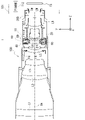
- FIG. 1 is a diagram showing a camera 1 including a lens barrel 100 including a blur correction device 80 according to this embodiment and a camera body 101.
- the lens barrel 100 is detachable from the camera body 101, but the lens barrel 100 and the camera body 101 may be integrated.
- the camera body 101 includes an image sensor IS, a control unit 112, and the like inside.
- the imaging element IS is composed of a photoelectric conversion element such as a CCD (Charge Coupled Device), for example, and converts the subject image formed by the imaging optical system (lens barrel 100 attached to the camera body 101) into an electrical signal. do.
- CCD Charge Coupled Device
- the control unit 112 includes a CPU (Central Processing Unit) and the like, and controls the overall operation of the camera 1 related to shooting, including focus driving in the camera body 101 and the attached lens barrel 100, and blur correction of captured images due to camera shake and the like. Overall control of operations.
- CPU Central Processing Unit
- the lens barrel 100 includes a fixed barrel 10. As shown in FIG. 1, the fixed cylinder 10 is composed of a plurality of parts in this embodiment, it may be composed of a single part. As shown in FIG. 1, the fixed barrel 10 is fixed with a lens mount LM that allows the lens barrel 100 to be detachable from the camera body 101 .
- the lens barrel 100 includes a plurality of lens groups L1 to L9 sequentially arranged along the common optical axis OA.
- the lens group L4 is held by a lens holding frame F4
- the lens group L6 is held by a lens holding frame F6
- the lens group L8 is held by a lens holding frame F8.
- Other lens groups are held by a fixed barrel 10 .
- Each of the lens groups L1 to L9 may be composed of one lens, or may be composed of a plurality of lenses.
- the lens group L6 is a vibration reduction (VR) lens, and can be moved within a plane perpendicular to the optical axis OA by the vibration reduction device 80 when performing vibration reduction.
- VR vibration reduction
- FIG. 2 is an exploded perspective view of the blur correction device 80 viewed from the camera body 101 side
- FIG. 3 is an exploded perspective view of the blur correction device 80 viewed from the subject side.
- the blur correction device 80 includes a movable frame 60, a fixed frame 30, and a lock ring 20. As shown in FIG.
- the movable frame 60 holds the lens group L6 via the lens holding frame F6 and moves within the XY plane perpendicular to the optical axis OA (Z axis).
- the fixed frame 30 includes a first fixed frame 40 and a second fixed frame 50.
- the first fixed frame 40 is a substantially annular member having a circular hole 41 in the center, and unlike the movable frame 60, it does not move within a plane perpendicular to the optical axis OA.
- the movable frame 60 is held so as to be relatively movable within a plane perpendicular to the optical axis OA. More specifically, the first fixed frame 40 holds the movable frame 60 via three steel balls 43 and three coil springs 42 .
- the movable frame 60 and the first fixed frame 40 are biased by a coil spring 42 in a direction of pressing against each other with the steel ball 43 sandwiched therebetween.
- the coil spring 42 connects the first fixed frame 40 and the movable frame 60 in the optical axis OA direction and prevents the first fixed frame 40 and the movable frame 60 from separating in the optical axis OA direction.
- the first fixed frame 40 and the movable frame 60 each have contact surfaces that contact the steel balls 43 at positions where the steel balls 43 are arranged.
- the steel ball 43 rotates between the contact surface of the first fixed frame 40 and the contact surface of the movable frame 60 . This allows the movable frame 60 to move in parallel with respect to the first fixed frame 40 in a low-friction state.
- a lens group L6 held by a movable frame 60 is moved within the XY plane by VCMs (voice coil motors) 90X and 90Y to correct image blurring.
- the VCMs 90X and 90Y are installed so as to push the center of gravity G of the lens group L6 parallel to the XY plane.
- the VCMs 90X and 90Y are arranged so that their positions in the optical axis OA direction are substantially the same.
- the -Z side surface of the VCM 90X and the -Z side surface of the VCM 90Y are arranged so as to be positioned in the same plane perpendicular to the optical axis OA.
- the VCM 90X is an actuator for driving the lens group L6 in the X-axis direction, and includes an X-axis direction driving coil 61X, a pair of X-axis direction driving magnets 52X, and a yoke 53X.
- the VCM 90Y is an actuator for driving the lens group L6 in the Y-axis direction, and includes a Y-axis direction driving coil 61Y, a pair of Y-axis direction driving magnets 52Y, and a yoke 53Y.
- the pair of magnets 52X for driving in the X-axis direction and the pair of magnets 52Y for driving in the Y-axis direction are in-plane dipole-polarized magnets having two poles polarized into N and S poles.
- the X-axis direction driving coil 61X and the Y-axis direction driving coil 61Y are attached to the movable frame 60.
- a yoke 53X is attached to the second fixed frame 50 at a position corresponding to the X-axis direction driving coil 61X, and an X-axis direction driving magnet 52X is attached to the yoke 53X.
- a yoke 53Y is attached to a position corresponding to the Y-axis direction driving coil 61Y of the movable frame 60, and a Y-axis direction driving magnet 52Y is attached to the yoke 53Y.
- FIG. 4 is a cross-sectional view of the blur correction device 80.
- FIG. As shown in FIG. 4, by applying a current to the Y-axis direction driving coil 61Y arranged between the Y-axis direction driving magnets 52Y, the Y-axis direction driving coil 61Y receives the Lorentz force and moves the movable frame. 60 is driven in the Y-axis direction. Thereby, the lens group L6 held by the movable frame 60 can be moved in the Y-axis direction.
- the yoke 53Y and the Y-axis direction driving magnet 52Y may be attached to the movable frame 60, and the Y-axis direction driving coil 61Y may be attached to the second fixed frame 50.
- FIG. That is, the VCM 90Y may be a moving coil type VCM or a moving magnet type VCM. The same applies to the VCM 90X, so detailed description will be omitted.
- the second fixed frame 50 is a substantially annular member having a circular hole 51 in its central portion. Unlike the movable frame 60, the second fixed frame 50 does not move within a plane perpendicular to the optical axis OA. As described above, the second fixed frame 50 is attached with the yokes 53X and 53Y.
- the lock ring 20 is a substantially annular member having a circular hole 21 in the center, and is a member for locking the movable frame 60 so that it does not move relative to the fixed frame 30 when shake correction is not performed. is.
- FIG. 5A and 5(B) are diagrams of the blur correction device 80 viewed from the camera body 101 side. Note that FIG. 5A shows a case where the lock ring 20 is in an unlocked position allowing movement of the lens unit L6 within a plane orthogonal to the optical axis OA, and FIG. is in the lock position that restricts the movement of the lens group L6 within the plane perpendicular to the optical axis OA.
- the lock ring 20 is rotated around the optical axis OA by a motor 70 (see FIGS. 2 and 3) attached to the second fixed frame 50, to a lock position that restricts the movement of the movable frame 60, and to release the restriction. Move between the unlocked position and
- a gear portion 22 is formed on the outer peripheral portion of the lock ring 20, and a pinion gear attached to the rotating shaft of the motor 70. It meshes with 71.
- the rotational force of the motor 70 is transmitted to the lock ring 20, and the forward and reverse rotation of the motor 70 drives the lock ring 20 to the locked position (FIG. 5(B)) and the unlocked position (FIG. 5(A)).
- a DC motor, a stepping motor, an ultrasonic motor, or the like can be used as the motor 70 .
- FIG. 6 is a perspective view of the blur correction device 80 viewed from the subject side.
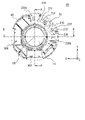
- FIG. 7 is a plan view of the blur correction device 80 viewed from the subject side.
- 8A is a cross-sectional view taken along line AA of FIG. 7, and
- FIG. 8B is a cross-sectional view taken along line BB of FIG.
- a first substrate 230a and a second substrate 230b are attached with screws to the surface of the first fixed frame 40 opposite to the movable frame 60 (surface on the -Z side).
- the first substrate 230 a and the second substrate 230 b are arranged between the inner circumference and the outer circumference of the first fixed frame 40 .
- the first substrate 230 a and the second substrate 230 b are arranged so as to surround part of the inner periphery of the first fixed frame 40 .
- the first substrate 230a is provided at a position facing the VCM 90Y across the optical axis OA on the XY plane.
- the second substrate 230b is provided at a position facing the VCM 90X across the optical axis OA on the XY plane.
- the motor 70 is provided between the first substrate 230a and the second substrate 230b attached to the first fixed frame 40 in the circumferential direction of a circle centered on the optical axis OA.
- the first substrate 230a has surfaces 231a and 232a that face each other in the optical axis OA direction. , VCM90X and VCM90Y. In other words, the first substrate 230a radially overlaps the VCMs 90X and 90Y. Also, the first substrate 230a does not overlap with any of the VCMs 90X and 90Y in the optical axis OA direction. In other words, the first substrate 230a and the VCMs 90X and 90Y are not laminated in the optical axis OA direction.
- the second substrate 230b has surfaces 231b and 232b facing each other in the optical axis OA direction.
- PL4 crosses VCM90X and VCM90Y.
- the second substrate 230b radially overlaps the VCMs 90X and 90Y.
- the second substrate 230b does not overlap with any of the VCMs 90X and 90Y in the optical axis OA direction.
- the second substrate 230b and the VCMs 90X and 90Y are not stacked in the optical axis OA direction.
- both the first substrate 230a and the second substrate 230b overlap the VCM 90X and the VCM 90Y in the radial direction, so the thickness of the blur correction device 80 in the optical axis OA direction can be reduced. That is, the blur correction device 80 can be thinned.
- the thickness of the blur correction device 80 in the optical axis OA direction can be reduced. That is, the blur correction device 80 can be thinned.
- FIG. 9A is a plan view of a motion compensation device 80' according to a comparative example as seen from the object side
- FIG. 9B is a cross-sectional view taken along line CC of FIG. 9A.
- the substrate 230 attached to the first fixed frame 40 is a single substrate surrounding the inner periphery of the first fixed frame 40 . Therefore, in the comparative example, the substrate 230 cannot be arranged such that the plane PL5 including the surface 231 of the substrate 230 and the plane PL6 including the surface 232 of the substrate 230 intersect the VCMs 90X and 90Y as shown in FIG. 9B. . That is, substrate 230 does not radially overlap VCMs 90X and 90Y. Also, the substrate 230 overlaps the VCM 90Y and the VCM 90X in the optical axis OA direction. That is, the substrate 230 and the VCMs 90Y and 90X are laminated in the optical axis OA direction.
- the vibration reduction device 80' becomes thicker than the vibration reduction device 80 according to the embodiment by at least the thickness of the substrate 230 in the optical axis OA direction. .
- the blur correction device 80 according to this embodiment can be made thinner than the configuration shown in the comparative example.
- the plane PL1 including the surface 231a of the first substrate 230a and the plane PL2 including the surface 232a intersect the VCMs 90X and 90Y, respectively. It's fine if you do. That is, the plane PL1 including the surface 231a may be located on the -Z side of the -Z side surfaces of the VCM 90X and VCM 90Y in the optical axis OA direction. The same applies to the second substrate 230b.
- the light receiving portion 242a of the light emitting portion 241a and the light receiving portion 242a included in the position detecting element 240a is located on the surface 232a of the first substrate 230a on the movable frame 60 side (+Z side). is provided.
- the light receiving section 242a is mounted on the surface 232a such that its length direction is parallel to the Y direction.
- a plane PL7 including the light receiving portion 242a and orthogonal to the optical axis OA intersects the magnet 52X of the VCM 90X and the magnet 52Y of the VCM 90Y.
- the light emitting part 241a is attached to the movable frame 60. Light emitted by the light emitting portion 241a is received by the light receiving portion 242a, whereby the position detecting element 240a detects the position of the lens group L6 moved by the VCM 90Y in the Y-axis direction on the XY plane. Therefore, the position detection element 240a is provided at a position facing the VCM 90Y across the optical axis OA on the XY plane.
- the light emitting section 241 a may be provided on the surface 232 a of the first substrate 230 a and the light receiving section 242 a may be provided on the movable frame 60 .
- the surface 232b on the movable frame 60 side (+Z side) of the second substrate 230b has a light receiving portion 241b and a light receiving portion 242b included in the position detection element 240b.
- a portion 242b is provided.
- the light receiving portion 242b is mounted on the surface 232b such that its length direction is parallel to the X-axis direction.
- a plane PL8 including the light receiving portion 242b and perpendicular to the optical axis OA intersects the magnet 52X of the VCM 90X and the magnet 52Y of the VCM 90Y.
- the light emitting part 241b is attached to the movable frame 60.
- the position detection element 240b detects the position of the lens group L6 moved by the VCM 90X in the X-axis direction on the XY plane by receiving the light emitted by the light emission part 241b with the light reception part 242b. Therefore, the position detection element 240b is provided at a position facing the VCM 90X across the optical axis OA on the XY plane.
- the light emitting portion 241 b may be provided on the surface 232 b of the second substrate 230 b and the light receiving portion 242 b may be provided on the movable frame 60 .
- the position detection elements 240a and 240b are, for example, PSDs (Position Sensitive Detectors), the light emitting units 241a and 241b are, for example, LEDs (Light Emitting Diodes), and the light receiving units 242a and 242b are, for example, PDs (Photo Diodes). is.
- PSDs Position Sensitive Detectors
- the light emitting units 241a and 241b are, for example, LEDs (Light Emitting Diodes)
- the light receiving units 242a and 242b are, for example, PDs (Photo Diodes).
- the light receiving sections 242a and 242b are brought closer to the center of gravity position G of the lens group L6 in the optical axis OA direction. can be placed.
- the mounting positions of the light emitting units 241a and 241b can be brought closer to the center of gravity position G, so that the driving efficiency of the lens group L6 by the VCMs 90X and 90Y can be improved.
- the mounting positions of the light emitting units 241a and 241b in the movable frame 60' must be set to the -Z side of the embodiment. must be located in Accordingly, since the movable frame 60' must be extended to the -Z side, the center of gravity of the movable frame 60' including the lens group L6 is shifted from the center of gravity G of the lens group L6 in the comparative example.
- the center of gravity of the movable frame 60' including the lens group L6 is aligned with the center of gravity G of the lens group L6. If it deviates from , the driving efficiency of the lens unit L6 will deteriorate.
- the first substrate 230a and the second substrate 230b are arranged at positions overlapping the VCM 90X and the VCM 90Y in the radial direction.
- the distance to the end face on the 40 side (-Z side) can be made shorter than in the comparative example. As a result, it is possible to prevent the position of the center of gravity of the movable frame 60' including the lens group L6 from deviating from the position of the center of gravity G of the lens group L6. .
- the FPC 211 is connected to the first substrate 230a, and the FPC 212 is connected to the second substrate 230b. Furthermore, the FPC 210 is commonly connected to the first substrate 230a and the second substrate 230b. That is, a connector 233 to which the FPC 211 is connected and a connector 234 to which the FPC 210 is connected are arranged on the first board 230a. A connector 236 to which the FPC 212 is connected and a connector 237 to which the FPC 210 is connected are arranged on the second board 230b.
- the FPC 211 supplies power from the first substrate 230a to the motor 70 and inputs control signals.
- the FPC 211 also inputs a rotation detection signal of the lock ring 20 to the first substrate 230a.
- the FPC 212 supplies power from the second substrate 230b to the position detection elements 240a and 240b, supplies power to the coils 61X and 61Y, and inputs control signals.
- the FPC 212 also inputs position detection signals from the position detection elements 240a and 240b to the second substrate 230b. Note that the FPC 211 may input/output power and signals to/from the position detection elements 240a and 240b and the coils 61X and 61Y.
- the FPC 212 may input/output electric power and signals to/from the motor 70 and the rotation detection portion of the lock ring 20 .
- the FPC 211 inputs and outputs power and signals to the position detection elements 240a and 240b and the rotation detection portion of the lock ring 20, and the FPC 212 inputs and outputs power and signals to the coils 61X and 61Y and the motor 70.
- the FPC 210 transmits electric power, drive signals, etc. to the motor 70, the rotation detection portion of the lock ring 20, the position detection elements 240a and 240b, and the coils 61X and 61Y from the main substrate 200 (see FIG. 1) arranged in the lens barrel 100. is input to the first substrate 230a or the second substrate 230b. Further, the FPC 210 receives the rotation detection signal of the lock ring 20, the detection signals of the position detection elements 240a and 240b, and the signals input from the FPCs 211 and 212, and outputs them to the main board 200 (see FIG. 1) arranged in the lens barrel 100. output to The main board 200 is connected to the control section 112 of the camera body 101 .
- the blur correction device 80 includes the movable frame 60 that holds the lens group L6, the fixed frame 30 that movably holds the movable frame 60, and the fixed frame 30.
- a second substrate 230b having surfaces 231b and 232b facing each other in the direction of the optical axis OA and connected to the VCMs 90X and 90Y;
- a first substrate 230a having a surface 231a and a surface 232a facing each other in the optical axis OA direction is provided.
- a plane PL2 including surface 232a of first substrate 230a intersects VCMs 90X and 90Y
- a plane PL4 including surface 232b of second substrate 230b intersects VCMs 90X and 90Y.
- the first substrate 230a and the second substrate 230b at least partially overlap the VCMs 90X and 90Y in the radial direction. Also, the first substrate 230a and the second substrate 230b and the VCMs 90X and 90Y do not overlap in the optical axis OA direction. As a result, as described above, the thickness of the motion compensation device 80 in the optical axis OA direction can be reduced, and the motion compensation device 80 can be made thinner. Also, the driving efficiency of the movable frame 60 can be improved.
- the fixed frame 30 has a substantially annular shape when viewed from the optical axis OA direction, and the first substrate 230a and the second substrate 230b overlap the fixed frame 30 in a plane perpendicular to the optical axis OA. is positioned between the inner and outer perimeters of the and surrounds a portion of the inner perimeter.
- the first substrate 230a and the second substrate 230b can be arranged so as to overlap the VCMs 90X and 90Y in the radial direction.
- the first substrate 230a and the second substrate 230b can be arranged without overlapping the VCMs 90X and 90Y in the optical axis OA direction.
- the blur correction device 80 has light emitting units 241a and 241b and light receiving units 242a and 242b, and is equipped with position detection elements 240a and 240b for detecting the position of the movable frame 60 with respect to the fixed frame 30,
- the first substrate 230a holds the light receiving portion 242a
- the second substrate 230b holds the light receiving portion 242b. Thereby, power can be supplied to the light receiving portions 242a and 242b without using wiring.
- FIG. 10 is a diagram for explaining diversion of the first substrate 230a and the second substrate 230b.
- the same first substrate 230a and second substrate 230b can be attached to the fixed frame 40A and the fixed frame 40B having different outer diameters.
- the first substrate 230a is arranged at a position facing the VCM 90Y with the optical axis OA interposed therebetween, and the second substrate 230b faces the VCM 90X with the optical axis OA interposed therebetween. placed in position. Since the light receiving portions 242a and 242b of the position detection elements 240a and 240b are provided on the first substrate 230a and the second substrate 230b, respectively, such arrangement improves the position detection accuracy of the movable frame 60. .
- the blur correction device 80 includes a lock ring 20 that regulates movement of the movable frame 60 with respect to the fixed frame 30, and a motor 70 that drives the lock ring 20.
- the motor 70 drives the optical axis OA. is arranged between the first substrate 230a and the second substrate 230b in the circumferential direction centered on . Thereby, the FPC 210 connected to the main substrate 200 can be easily connected to the first substrate 230a and the second substrate 230b.
- the two first substrates 230a and the second substrate 230b are attached to the first fixing frame 40, but as shown in FIG. 11A, one substrate 230c is attached to the first fixing frame. 40 may be attached.
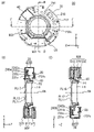
- FIG. 11(A) is a plan view showing a substrate 230c according to another embodiment
- FIG. 11(B) is a cross-sectional view taken along line DD of FIG. 11(A), and FIG. , and a cross-sectional view taken along line EE of FIG. 11(A).
- one substrate 230c has a shape surrounding part of the inner periphery of the first fixed frame 40.
- the motor 70 may be arranged by providing a hole through which the motor 70 passes through the substrate 230c, or the motor 70 may be arranged in an area where the substrate 230c does not exist. . Note that three or more substrates may be attached to the first fixed frame 40 .
- the substrate 230c has surfaces 231c and 232c facing each other in the optical axis OA direction, and a plane PL11 including the surface 231c and a plane PL12 including the surface 232c are Intersects VCM 90X, 90Y. That is, substrate 230c radially overlaps VCMs 90X and 90Y. Also, the substrate 230c overlaps neither the VCM 90X nor the VCM 90Y in the optical axis OA direction.
- a light receiving portion 242a of the position detection element 240a is provided at a position facing the VCM 90Y
- a position detection element 240b is provided at a position facing the VCM 90X.
- a plane PL17 including the light receiving portion 242a and a plane PL18 including the light receiving portion 242b intersect the magnets 52Y and 52X of the VCMs 90Y and 90X, respectively. In this way, even if only one substrate 230c is used, the substrate 230c surrounds part of the inner periphery of the first fixing frame 40 (but does not surround the entire inner periphery). It can be made thinner. Also in another embodiment, the plane PL12 including at least the surface 232c should intersect the VCMs 90Y and 90X.
- the moving lens type blurring correction device 80 that drives the lens group L6 has been described, but the present invention is not limited to this, and can also be applied to a moving image pickup device type blurring correction device that drives the image pickup device. can be done.
- the blur correction device described in the above embodiments can be applied not only to compact digital cameras and single-lens reflex digital cameras, but also to optical devices such as video cameras, binoculars, microscopes, telescopes, and mobile phones.
- Lock ring 30 Fixed frame 40 First fixed frame 50 Second fixed frame 52X, 52Y Magnet 53X, 53Y Yoke 60 Movable frame 61X, 61Y Coil 70 Motor 80 Shake correction device 90X, 90Y VCM 112 control unit L6 lens group 200 main substrate 230a first substrate 230b second substrate 230c substrates 231a, 232a first substrate surfaces 231b, 232b second substrate surfaces 240a, 240b position detection elements 241a, 241b light emitting units 242a, 242b light receiving Department
Landscapes
- Physics & Mathematics (AREA)
- General Physics & Mathematics (AREA)
- Adjustment Of Camera Lenses (AREA)
Priority Applications (2)
| Application Number | Priority Date | Filing Date | Title |
|---|---|---|---|
| JP2023536724A JPWO2023002927A1 (https=) | 2021-07-19 | 2022-07-14 | |
| JP2025269267A JP2026034713A (ja) | 2021-07-19 | 2025-12-19 | ブレ補正装置、レンズ鏡筒、及び撮像装置 |
Applications Claiming Priority (2)
| Application Number | Priority Date | Filing Date | Title |
|---|---|---|---|
| JP2021118440 | 2021-07-19 | ||
| JP2021-118440 | 2021-07-19 |
Publications (1)
| Publication Number | Publication Date |
|---|---|
| WO2023002927A1 true WO2023002927A1 (ja) | 2023-01-26 |
Family
ID=84979285
Family Applications (1)
| Application Number | Title | Priority Date | Filing Date |
|---|---|---|---|
| PCT/JP2022/027781 Ceased WO2023002927A1 (ja) | 2021-07-19 | 2022-07-14 | ブレ補正装置、レンズ鏡筒、及び撮像装置 |
Country Status (2)
| Country | Link |
|---|---|
| JP (2) | JPWO2023002927A1 (https=) |
| WO (1) | WO2023002927A1 (https=) |
Citations (6)
| Publication number | Priority date | Publication date | Assignee | Title |
|---|---|---|---|---|
| JPH09269520A (ja) * | 1996-03-29 | 1997-10-14 | Canon Inc | 像振れ補正装置 |
| JPH10254013A (ja) * | 1997-03-11 | 1998-09-25 | Nikon Corp | ブレ補正装置とレンズ鏡筒 |
| JP2002182257A (ja) * | 2000-12-15 | 2002-06-26 | Canon Inc | 補正光学装置 |
| JP2008209434A (ja) * | 2007-02-23 | 2008-09-11 | Nikon Corp | 相対移動部材、ブレ補正装置および光学装置 |
| JP2010224121A (ja) * | 2009-03-23 | 2010-10-07 | Canon Inc | レンズ鏡筒及びそれを有する光学機器 |
| JP2012022183A (ja) * | 2010-07-15 | 2012-02-02 | Canon Inc | 振れ補正装置及び撮像装置 |
Family Cites Families (4)
| Publication number | Priority date | Publication date | Assignee | Title |
|---|---|---|---|---|
| JP2004085819A (ja) * | 2002-08-26 | 2004-03-18 | Canon Inc | 振れ補正装置、レンズ鏡筒及び撮影装置 |
| JP4493046B2 (ja) * | 2005-07-15 | 2010-06-30 | パナソニック株式会社 | レンズ鏡筒及びそのレンズ鏡筒を備えた撮像装置 |
| JP2011022365A (ja) * | 2009-07-16 | 2011-02-03 | Canon Inc | 像振れ補正装置及びそれを有するレンズ鏡筒 |
| WO2013105515A1 (ja) * | 2012-01-13 | 2013-07-18 | パナソニック株式会社 | レンズ鏡筒 |
-
2022
- 2022-07-14 JP JP2023536724A patent/JPWO2023002927A1/ja active Pending
- 2022-07-14 WO PCT/JP2022/027781 patent/WO2023002927A1/ja not_active Ceased
-
2025
- 2025-12-19 JP JP2025269267A patent/JP2026034713A/ja active Pending
Patent Citations (6)
| Publication number | Priority date | Publication date | Assignee | Title |
|---|---|---|---|---|
| JPH09269520A (ja) * | 1996-03-29 | 1997-10-14 | Canon Inc | 像振れ補正装置 |
| JPH10254013A (ja) * | 1997-03-11 | 1998-09-25 | Nikon Corp | ブレ補正装置とレンズ鏡筒 |
| JP2002182257A (ja) * | 2000-12-15 | 2002-06-26 | Canon Inc | 補正光学装置 |
| JP2008209434A (ja) * | 2007-02-23 | 2008-09-11 | Nikon Corp | 相対移動部材、ブレ補正装置および光学装置 |
| JP2010224121A (ja) * | 2009-03-23 | 2010-10-07 | Canon Inc | レンズ鏡筒及びそれを有する光学機器 |
| JP2012022183A (ja) * | 2010-07-15 | 2012-02-02 | Canon Inc | 振れ補正装置及び撮像装置 |
Also Published As
| Publication number | Publication date |
|---|---|
| JP2026034713A (ja) | 2026-02-27 |
| JPWO2023002927A1 (https=) | 2023-01-26 |
Similar Documents
| Publication | Publication Date | Title |
|---|---|---|
| CN113050341B (zh) | 相机模块 | |
| JP7702449B2 (ja) | レンズ駆動装置、カメラモジュール及び光学機器 | |
| US10284780B2 (en) | Auto focus and optical image stabilization with roll compensation in a compact folded camera | |
| US11860512B2 (en) | Camera module | |
| US12265279B2 (en) | Optical path conversion module, and camera module and portable terminal including the same | |
| US10845612B2 (en) | Camera module and electronic device including same | |
| US11852844B2 (en) | Optical system | |
| JP5038046B2 (ja) | 像ぶれ補正装置および撮像装置 | |
| KR20110080590A (ko) | 흔들림 보정 모듈 및 이를 구비하는 카메라 모듈 | |
| US10379422B2 (en) | Position detecting apparatus and image stabilization apparatus to which position detecting apparatus is applied | |
| JP2015011353A (ja) | 光路の切り換えが可能な光学震動防止機構 | |
| US10379373B2 (en) | Image stabilization device | |
| WO2014208195A1 (ja) | レンズユニット、及び撮像装置 | |
| JP4493046B2 (ja) | レンズ鏡筒及びそのレンズ鏡筒を備えた撮像装置 | |
| TWI418844B (zh) | 可變焦攝影模組 | |
| JP5289994B2 (ja) | 光学補正ユニット、レンズ鏡筒及び撮像装置 | |
| CN118377105A (zh) | 镜头装置和摄像装置 | |
| JP7130498B2 (ja) | レンズ装置および撮像装置 | |
| JP5114970B2 (ja) | 相対移動部材、ブレ補正装置および光学装置 | |
| WO2023002927A1 (ja) | ブレ補正装置、レンズ鏡筒、及び撮像装置 | |
| JP2009169291A (ja) | 光学機器 | |
| WO2022134189A1 (zh) | 摄像装置用防振机构、光学系统、相机及电子设备 | |
| CN117849980A (zh) | 光学元件驱动装置、照相机模块以及照相机搭载装置 | |
| JP7639637B2 (ja) | レンズ鏡筒及び撮像装置 | |
| JP4731854B2 (ja) | 光学機器 |
Legal Events
| Date | Code | Title | Description |
|---|---|---|---|
| 121 | Ep: the epo has been informed by wipo that ep was designated in this application |
Ref document number: 22845861 Country of ref document: EP Kind code of ref document: A1 |
|
| WWE | Wipo information: entry into national phase |
Ref document number: 2023536724 Country of ref document: JP |
|
| NENP | Non-entry into the national phase |
Ref country code: DE |
|
| 122 | Ep: pct application non-entry in european phase |
Ref document number: 22845861 Country of ref document: EP Kind code of ref document: A1 |