WO2023002927A1 - ブレ補正装置、レンズ鏡筒、及び撮像装置 - Google Patents
ブレ補正装置、レンズ鏡筒、及び撮像装置 Download PDFInfo
- Publication number
- WO2023002927A1 WO2023002927A1 PCT/JP2022/027781 JP2022027781W WO2023002927A1 WO 2023002927 A1 WO2023002927 A1 WO 2023002927A1 JP 2022027781 W JP2022027781 W JP 2022027781W WO 2023002927 A1 WO2023002927 A1 WO 2023002927A1
- Authority
- WO
- WIPO (PCT)
- Prior art keywords
- substrate
- optical axis
- blur correction
- correction device
- fixed frame
- Prior art date
Links
- 238000003384 imaging method Methods 0.000 title claims description 7
- 239000000758 substrate Substances 0.000 claims abstract description 139
- 230000003287 optical effect Effects 0.000 claims abstract description 66
- 238000001514 detection method Methods 0.000 claims description 32
- 230000000052 comparative effect Effects 0.000 description 11
- 230000005484 gravity Effects 0.000 description 11
- 238000010586 diagram Methods 0.000 description 6
- 229910000831 Steel Inorganic materials 0.000 description 5
- 239000010959 steel Substances 0.000 description 5
- 239000000470 constituent Substances 0.000 description 2
- 108700002808 N-Me-Phe(3)- morphiceptin Proteins 0.000 description 1
- 238000006243 chemical reaction Methods 0.000 description 1
- 238000012986 modification Methods 0.000 description 1
- 230000004048 modification Effects 0.000 description 1
- 230000002093 peripheral effect Effects 0.000 description 1
- 230000011514 reflex Effects 0.000 description 1
Images


Classifications
-
- G—PHYSICS
- G03—PHOTOGRAPHY; CINEMATOGRAPHY; ANALOGOUS TECHNIQUES USING WAVES OTHER THAN OPTICAL WAVES; ELECTROGRAPHY; HOLOGRAPHY
- G03B—APPARATUS OR ARRANGEMENTS FOR TAKING PHOTOGRAPHS OR FOR PROJECTING OR VIEWING THEM; APPARATUS OR ARRANGEMENTS EMPLOYING ANALOGOUS TECHNIQUES USING WAVES OTHER THAN OPTICAL WAVES; ACCESSORIES THEREFOR
- G03B5/00—Adjustment of optical system relative to image or object surface other than for focusing
Definitions
- An imaging device includes a blur correction device that suppresses blurring of a captured image due to camera shake or the like. It is desired to reduce the size of the blur correction device (see Patent Document 1, for example).
- the blur correction device includes a lens holding frame that holds a lens, a fixed frame that movably holds the lens holding frame, and the lens holding frame with respect to the fixed frame as an optical axis. and a substrate having a first surface and a second surface facing each other in an optical axis direction and connected to the driving unit, including the first surface of the substrate.
- a first plane intersects the drive.
- the lens barrel includes the blur correction device.
- an imaging device includes the blur correction device.
- FIG. 1 is a diagram showing a camera including a lens barrel including a blur correction device according to one embodiment, and a camera body.
- FIG. 2 is an exploded perspective view of the blur correction device viewed from the camera body side.
- FIG. 3 is an exploded perspective view of the blur correction device viewed from the object side.
- FIG. 4 is a cross-sectional view of the blur correction device.
- FIGS. 5A and 5B are diagrams of the blur correction device as seen from the camera body side.
- FIG. 6 is a perspective view of the blur correction device viewed from the subject side.
- FIG. 7 is a plan view of the blur correction device viewed from the subject side.
- 8A is a cross-sectional view taken along the line AA of FIG. 7, and FIG.
- FIG. 8B is a cross-sectional view taken along the line BB of FIG.
- FIG. 9(A) is a plan view of a blur correction device according to a comparative example as seen from the object side
- FIG. 9(B) is a cross-sectional view taken along line CC of FIG. 9(A).
- FIG. 10 is a diagram for explaining diversion of the first substrate and the second substrate.
- 11A is a plan view showing a substrate according to another embodiment
- FIG. 11B is a cross-sectional view taken along line DD of FIG. 11A
- FIG. 11(A) is a cross-sectional view taken along line EE.
- the blur correction device 80 according to one embodiment will be described in detail with reference to the drawings.
- the +Z direction is the direction from the object toward the camera body 101 at the camera position (hereinafter referred to as normal position) when the photographer takes a landscape image with the optical axis OA horizontal.
- the direction toward the right side when viewed from the camera body 101 side at the normal position is defined as the +X direction.
- the upward direction in the normal position is the +Y direction.
- FIG. 1 is a diagram showing a camera 1 including a lens barrel 100 including a blur correction device 80 according to this embodiment and a camera body 101.
- the lens barrel 100 is detachable from the camera body 101, but the lens barrel 100 and the camera body 101 may be integrated.
- the camera body 101 includes an image sensor IS, a control unit 112, and the like inside.
- the imaging element IS is composed of a photoelectric conversion element such as a CCD (Charge Coupled Device), for example, and converts the subject image formed by the imaging optical system (lens barrel 100 attached to the camera body 101) into an electrical signal. do.
- CCD Charge Coupled Device
- the control unit 112 includes a CPU (Central Processing Unit) and the like, and controls the overall operation of the camera 1 related to shooting, including focus driving in the camera body 101 and the attached lens barrel 100, and blur correction of captured images due to camera shake and the like. Overall control of operations.
- CPU Central Processing Unit
- the lens barrel 100 includes a fixed barrel 10. As shown in FIG. 1, the fixed cylinder 10 is composed of a plurality of parts in this embodiment, it may be composed of a single part. As shown in FIG. 1, the fixed barrel 10 is fixed with a lens mount LM that allows the lens barrel 100 to be detachable from the camera body 101 .
- the lens barrel 100 includes a plurality of lens groups L1 to L9 sequentially arranged along the common optical axis OA.
- the lens group L4 is held by a lens holding frame F4
- the lens group L6 is held by a lens holding frame F6
- the lens group L8 is held by a lens holding frame F8.
- Other lens groups are held by a fixed barrel 10 .
- Each of the lens groups L1 to L9 may be composed of one lens, or may be composed of a plurality of lenses.
- the lens group L6 is a vibration reduction (VR) lens, and can be moved within a plane perpendicular to the optical axis OA by the vibration reduction device 80 when performing vibration reduction.
- VR vibration reduction
- FIG. 2 is an exploded perspective view of the blur correction device 80 viewed from the camera body 101 side
- FIG. 3 is an exploded perspective view of the blur correction device 80 viewed from the subject side.
- the blur correction device 80 includes a movable frame 60, a fixed frame 30, and a lock ring 20. As shown in FIG.
- the movable frame 60 holds the lens group L6 via the lens holding frame F6 and moves within the XY plane perpendicular to the optical axis OA (Z axis).
- the fixed frame 30 includes a first fixed frame 40 and a second fixed frame 50.
- the first fixed frame 40 is a substantially annular member having a circular hole 41 in the center, and unlike the movable frame 60, it does not move within a plane perpendicular to the optical axis OA.
- the movable frame 60 is held so as to be relatively movable within a plane perpendicular to the optical axis OA. More specifically, the first fixed frame 40 holds the movable frame 60 via three steel balls 43 and three coil springs 42 .
- the movable frame 60 and the first fixed frame 40 are biased by a coil spring 42 in a direction of pressing against each other with the steel ball 43 sandwiched therebetween.
- the coil spring 42 connects the first fixed frame 40 and the movable frame 60 in the optical axis OA direction and prevents the first fixed frame 40 and the movable frame 60 from separating in the optical axis OA direction.
- the first fixed frame 40 and the movable frame 60 each have contact surfaces that contact the steel balls 43 at positions where the steel balls 43 are arranged.
- the steel ball 43 rotates between the contact surface of the first fixed frame 40 and the contact surface of the movable frame 60 . This allows the movable frame 60 to move in parallel with respect to the first fixed frame 40 in a low-friction state.
- a lens group L6 held by a movable frame 60 is moved within the XY plane by VCMs (voice coil motors) 90X and 90Y to correct image blurring.
- the VCMs 90X and 90Y are installed so as to push the center of gravity G of the lens group L6 parallel to the XY plane.
- the VCMs 90X and 90Y are arranged so that their positions in the optical axis OA direction are substantially the same.
- the -Z side surface of the VCM 90X and the -Z side surface of the VCM 90Y are arranged so as to be positioned in the same plane perpendicular to the optical axis OA.
- the VCM 90X is an actuator for driving the lens group L6 in the X-axis direction, and includes an X-axis direction driving coil 61X, a pair of X-axis direction driving magnets 52X, and a yoke 53X.
- the VCM 90Y is an actuator for driving the lens group L6 in the Y-axis direction, and includes a Y-axis direction driving coil 61Y, a pair of Y-axis direction driving magnets 52Y, and a yoke 53Y.
- the pair of magnets 52X for driving in the X-axis direction and the pair of magnets 52Y for driving in the Y-axis direction are in-plane dipole-polarized magnets having two poles polarized into N and S poles.
- the X-axis direction driving coil 61X and the Y-axis direction driving coil 61Y are attached to the movable frame 60.
- a yoke 53X is attached to the second fixed frame 50 at a position corresponding to the X-axis direction driving coil 61X, and an X-axis direction driving magnet 52X is attached to the yoke 53X.
- a yoke 53Y is attached to a position corresponding to the Y-axis direction driving coil 61Y of the movable frame 60, and a Y-axis direction driving magnet 52Y is attached to the yoke 53Y.
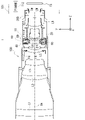
- FIG. 4 is a cross-sectional view of the blur correction device 80.
- FIG. As shown in FIG. 4, by applying a current to the Y-axis direction driving coil 61Y arranged between the Y-axis direction driving magnets 52Y, the Y-axis direction driving coil 61Y receives the Lorentz force and moves the movable frame. 60 is driven in the Y-axis direction. Thereby, the lens group L6 held by the movable frame 60 can be moved in the Y-axis direction.
- the yoke 53Y and the Y-axis direction driving magnet 52Y may be attached to the movable frame 60, and the Y-axis direction driving coil 61Y may be attached to the second fixed frame 50.
- FIG. That is, the VCM 90Y may be a moving coil type VCM or a moving magnet type VCM. The same applies to the VCM 90X, so detailed description will be omitted.
- the second fixed frame 50 is a substantially annular member having a circular hole 51 in its central portion. Unlike the movable frame 60, the second fixed frame 50 does not move within a plane perpendicular to the optical axis OA. As described above, the second fixed frame 50 is attached with the yokes 53X and 53Y.
- the lock ring 20 is a substantially annular member having a circular hole 21 in the center, and is a member for locking the movable frame 60 so that it does not move relative to the fixed frame 30 when shake correction is not performed. is.
- FIG. 5A and 5(B) are diagrams of the blur correction device 80 viewed from the camera body 101 side. Note that FIG. 5A shows a case where the lock ring 20 is in an unlocked position allowing movement of the lens unit L6 within a plane orthogonal to the optical axis OA, and FIG. is in the lock position that restricts the movement of the lens group L6 within the plane perpendicular to the optical axis OA.
- the lock ring 20 is rotated around the optical axis OA by a motor 70 (see FIGS. 2 and 3) attached to the second fixed frame 50, to a lock position that restricts the movement of the movable frame 60, and to release the restriction. Move between the unlocked position and
- a gear portion 22 is formed on the outer peripheral portion of the lock ring 20, and a pinion gear attached to the rotating shaft of the motor 70. It meshes with 71.
- the rotational force of the motor 70 is transmitted to the lock ring 20, and the forward and reverse rotation of the motor 70 drives the lock ring 20 to the locked position (FIG. 5(B)) and the unlocked position (FIG. 5(A)).
- a DC motor, a stepping motor, an ultrasonic motor, or the like can be used as the motor 70 .
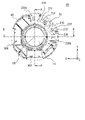
- FIG. 6 is a perspective view of the blur correction device 80 viewed from the subject side.
- FIG. 7 is a plan view of the blur correction device 80 viewed from the subject side.
- 8A is a cross-sectional view taken along line AA of FIG. 7, and
- FIG. 8B is a cross-sectional view taken along line BB of FIG.
- a first substrate 230a and a second substrate 230b are attached with screws to the surface of the first fixed frame 40 opposite to the movable frame 60 (surface on the -Z side).
- the first substrate 230 a and the second substrate 230 b are arranged between the inner circumference and the outer circumference of the first fixed frame 40 .
- the first substrate 230 a and the second substrate 230 b are arranged so as to surround part of the inner periphery of the first fixed frame 40 .
- the first substrate 230a is provided at a position facing the VCM 90Y across the optical axis OA on the XY plane.
- the second substrate 230b is provided at a position facing the VCM 90X across the optical axis OA on the XY plane.
- the motor 70 is provided between the first substrate 230a and the second substrate 230b attached to the first fixed frame 40 in the circumferential direction of a circle centered on the optical axis OA.
- the first substrate 230a has surfaces 231a and 232a that face each other in the optical axis OA direction. , VCM90X and VCM90Y. In other words, the first substrate 230a radially overlaps the VCMs 90X and 90Y. Also, the first substrate 230a does not overlap with any of the VCMs 90X and 90Y in the optical axis OA direction. In other words, the first substrate 230a and the VCMs 90X and 90Y are not laminated in the optical axis OA direction.
- the second substrate 230b has surfaces 231b and 232b facing each other in the optical axis OA direction.
- PL4 crosses VCM90X and VCM90Y.
- the second substrate 230b radially overlaps the VCMs 90X and 90Y.
- the second substrate 230b does not overlap with any of the VCMs 90X and 90Y in the optical axis OA direction.
- the second substrate 230b and the VCMs 90X and 90Y are not stacked in the optical axis OA direction.
- both the first substrate 230a and the second substrate 230b overlap the VCM 90X and the VCM 90Y in the radial direction, so the thickness of the blur correction device 80 in the optical axis OA direction can be reduced. That is, the blur correction device 80 can be thinned.
- the thickness of the blur correction device 80 in the optical axis OA direction can be reduced. That is, the blur correction device 80 can be thinned.
- FIG. 9A is a plan view of a motion compensation device 80' according to a comparative example as seen from the object side
- FIG. 9B is a cross-sectional view taken along line CC of FIG. 9A.
- the substrate 230 attached to the first fixed frame 40 is a single substrate surrounding the inner periphery of the first fixed frame 40 . Therefore, in the comparative example, the substrate 230 cannot be arranged such that the plane PL5 including the surface 231 of the substrate 230 and the plane PL6 including the surface 232 of the substrate 230 intersect the VCMs 90X and 90Y as shown in FIG. 9B. . That is, substrate 230 does not radially overlap VCMs 90X and 90Y. Also, the substrate 230 overlaps the VCM 90Y and the VCM 90X in the optical axis OA direction. That is, the substrate 230 and the VCMs 90Y and 90X are laminated in the optical axis OA direction.
- the vibration reduction device 80' becomes thicker than the vibration reduction device 80 according to the embodiment by at least the thickness of the substrate 230 in the optical axis OA direction. .
- the blur correction device 80 according to this embodiment can be made thinner than the configuration shown in the comparative example.
- the plane PL1 including the surface 231a of the first substrate 230a and the plane PL2 including the surface 232a intersect the VCMs 90X and 90Y, respectively. It's fine if you do. That is, the plane PL1 including the surface 231a may be located on the -Z side of the -Z side surfaces of the VCM 90X and VCM 90Y in the optical axis OA direction. The same applies to the second substrate 230b.
- the light receiving portion 242a of the light emitting portion 241a and the light receiving portion 242a included in the position detecting element 240a is located on the surface 232a of the first substrate 230a on the movable frame 60 side (+Z side). is provided.
- the light receiving section 242a is mounted on the surface 232a such that its length direction is parallel to the Y direction.
- a plane PL7 including the light receiving portion 242a and orthogonal to the optical axis OA intersects the magnet 52X of the VCM 90X and the magnet 52Y of the VCM 90Y.
- the light emitting part 241a is attached to the movable frame 60. Light emitted by the light emitting portion 241a is received by the light receiving portion 242a, whereby the position detecting element 240a detects the position of the lens group L6 moved by the VCM 90Y in the Y-axis direction on the XY plane. Therefore, the position detection element 240a is provided at a position facing the VCM 90Y across the optical axis OA on the XY plane.
- the light emitting section 241 a may be provided on the surface 232 a of the first substrate 230 a and the light receiving section 242 a may be provided on the movable frame 60 .
- the surface 232b on the movable frame 60 side (+Z side) of the second substrate 230b has a light receiving portion 241b and a light receiving portion 242b included in the position detection element 240b.
- a portion 242b is provided.
- the light receiving portion 242b is mounted on the surface 232b such that its length direction is parallel to the X-axis direction.
- a plane PL8 including the light receiving portion 242b and perpendicular to the optical axis OA intersects the magnet 52X of the VCM 90X and the magnet 52Y of the VCM 90Y.
- the light emitting part 241b is attached to the movable frame 60.
- the position detection element 240b detects the position of the lens group L6 moved by the VCM 90X in the X-axis direction on the XY plane by receiving the light emitted by the light emission part 241b with the light reception part 242b. Therefore, the position detection element 240b is provided at a position facing the VCM 90X across the optical axis OA on the XY plane.
- the light emitting portion 241 b may be provided on the surface 232 b of the second substrate 230 b and the light receiving portion 242 b may be provided on the movable frame 60 .
- the position detection elements 240a and 240b are, for example, PSDs (Position Sensitive Detectors), the light emitting units 241a and 241b are, for example, LEDs (Light Emitting Diodes), and the light receiving units 242a and 242b are, for example, PDs (Photo Diodes). is.
- PSDs Position Sensitive Detectors
- the light emitting units 241a and 241b are, for example, LEDs (Light Emitting Diodes)
- the light receiving units 242a and 242b are, for example, PDs (Photo Diodes).
- the light receiving sections 242a and 242b are brought closer to the center of gravity position G of the lens group L6 in the optical axis OA direction. can be placed.
- the mounting positions of the light emitting units 241a and 241b can be brought closer to the center of gravity position G, so that the driving efficiency of the lens group L6 by the VCMs 90X and 90Y can be improved.
- the mounting positions of the light emitting units 241a and 241b in the movable frame 60' must be set to the -Z side of the embodiment. must be located in Accordingly, since the movable frame 60' must be extended to the -Z side, the center of gravity of the movable frame 60' including the lens group L6 is shifted from the center of gravity G of the lens group L6 in the comparative example.
- the center of gravity of the movable frame 60' including the lens group L6 is aligned with the center of gravity G of the lens group L6. If it deviates from , the driving efficiency of the lens unit L6 will deteriorate.
- the first substrate 230a and the second substrate 230b are arranged at positions overlapping the VCM 90X and the VCM 90Y in the radial direction.
- the distance to the end face on the 40 side (-Z side) can be made shorter than in the comparative example. As a result, it is possible to prevent the position of the center of gravity of the movable frame 60' including the lens group L6 from deviating from the position of the center of gravity G of the lens group L6. .
- the FPC 211 is connected to the first substrate 230a, and the FPC 212 is connected to the second substrate 230b. Furthermore, the FPC 210 is commonly connected to the first substrate 230a and the second substrate 230b. That is, a connector 233 to which the FPC 211 is connected and a connector 234 to which the FPC 210 is connected are arranged on the first board 230a. A connector 236 to which the FPC 212 is connected and a connector 237 to which the FPC 210 is connected are arranged on the second board 230b.
- the FPC 211 supplies power from the first substrate 230a to the motor 70 and inputs control signals.
- the FPC 211 also inputs a rotation detection signal of the lock ring 20 to the first substrate 230a.
- the FPC 212 supplies power from the second substrate 230b to the position detection elements 240a and 240b, supplies power to the coils 61X and 61Y, and inputs control signals.
- the FPC 212 also inputs position detection signals from the position detection elements 240a and 240b to the second substrate 230b. Note that the FPC 211 may input/output power and signals to/from the position detection elements 240a and 240b and the coils 61X and 61Y.
- the FPC 212 may input/output electric power and signals to/from the motor 70 and the rotation detection portion of the lock ring 20 .
- the FPC 211 inputs and outputs power and signals to the position detection elements 240a and 240b and the rotation detection portion of the lock ring 20, and the FPC 212 inputs and outputs power and signals to the coils 61X and 61Y and the motor 70.
- the FPC 210 transmits electric power, drive signals, etc. to the motor 70, the rotation detection portion of the lock ring 20, the position detection elements 240a and 240b, and the coils 61X and 61Y from the main substrate 200 (see FIG. 1) arranged in the lens barrel 100. is input to the first substrate 230a or the second substrate 230b. Further, the FPC 210 receives the rotation detection signal of the lock ring 20, the detection signals of the position detection elements 240a and 240b, and the signals input from the FPCs 211 and 212, and outputs them to the main board 200 (see FIG. 1) arranged in the lens barrel 100. output to The main board 200 is connected to the control section 112 of the camera body 101 .
- the blur correction device 80 includes the movable frame 60 that holds the lens group L6, the fixed frame 30 that movably holds the movable frame 60, and the fixed frame 30.
- a second substrate 230b having surfaces 231b and 232b facing each other in the direction of the optical axis OA and connected to the VCMs 90X and 90Y;
- a first substrate 230a having a surface 231a and a surface 232a facing each other in the optical axis OA direction is provided.
- a plane PL2 including surface 232a of first substrate 230a intersects VCMs 90X and 90Y
- a plane PL4 including surface 232b of second substrate 230b intersects VCMs 90X and 90Y.
- the first substrate 230a and the second substrate 230b at least partially overlap the VCMs 90X and 90Y in the radial direction. Also, the first substrate 230a and the second substrate 230b and the VCMs 90X and 90Y do not overlap in the optical axis OA direction. As a result, as described above, the thickness of the motion compensation device 80 in the optical axis OA direction can be reduced, and the motion compensation device 80 can be made thinner. Also, the driving efficiency of the movable frame 60 can be improved.
- the fixed frame 30 has a substantially annular shape when viewed from the optical axis OA direction, and the first substrate 230a and the second substrate 230b overlap the fixed frame 30 in a plane perpendicular to the optical axis OA. is positioned between the inner and outer perimeters of the and surrounds a portion of the inner perimeter.
- the first substrate 230a and the second substrate 230b can be arranged so as to overlap the VCMs 90X and 90Y in the radial direction.
- the first substrate 230a and the second substrate 230b can be arranged without overlapping the VCMs 90X and 90Y in the optical axis OA direction.
- the blur correction device 80 has light emitting units 241a and 241b and light receiving units 242a and 242b, and is equipped with position detection elements 240a and 240b for detecting the position of the movable frame 60 with respect to the fixed frame 30,
- the first substrate 230a holds the light receiving portion 242a
- the second substrate 230b holds the light receiving portion 242b. Thereby, power can be supplied to the light receiving portions 242a and 242b without using wiring.
- FIG. 10 is a diagram for explaining diversion of the first substrate 230a and the second substrate 230b.
- the same first substrate 230a and second substrate 230b can be attached to the fixed frame 40A and the fixed frame 40B having different outer diameters.
- the first substrate 230a is arranged at a position facing the VCM 90Y with the optical axis OA interposed therebetween, and the second substrate 230b faces the VCM 90X with the optical axis OA interposed therebetween. placed in position. Since the light receiving portions 242a and 242b of the position detection elements 240a and 240b are provided on the first substrate 230a and the second substrate 230b, respectively, such arrangement improves the position detection accuracy of the movable frame 60. .
- the blur correction device 80 includes a lock ring 20 that regulates movement of the movable frame 60 with respect to the fixed frame 30, and a motor 70 that drives the lock ring 20.
- the motor 70 drives the optical axis OA. is arranged between the first substrate 230a and the second substrate 230b in the circumferential direction centered on . Thereby, the FPC 210 connected to the main substrate 200 can be easily connected to the first substrate 230a and the second substrate 230b.
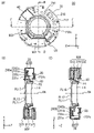
- the two first substrates 230a and the second substrate 230b are attached to the first fixing frame 40, but as shown in FIG. 11A, one substrate 230c is attached to the first fixing frame. 40 may be attached.
- FIG. 11(A) is a plan view showing a substrate 230c according to another embodiment
- FIG. 11(B) is a cross-sectional view taken along line DD of FIG. 11(A), and FIG. , and a cross-sectional view taken along line EE of FIG. 11(A).
- one substrate 230c has a shape surrounding part of the inner periphery of the first fixed frame 40.
- the motor 70 may be arranged by providing a hole through which the motor 70 passes through the substrate 230c, or the motor 70 may be arranged in an area where the substrate 230c does not exist. . Note that three or more substrates may be attached to the first fixed frame 40 .
- the substrate 230c has surfaces 231c and 232c facing each other in the optical axis OA direction, and a plane PL11 including the surface 231c and a plane PL12 including the surface 232c are Intersects VCM 90X, 90Y. That is, substrate 230c radially overlaps VCMs 90X and 90Y. Also, the substrate 230c overlaps neither the VCM 90X nor the VCM 90Y in the optical axis OA direction.
- a light receiving portion 242a of the position detection element 240a is provided at a position facing the VCM 90Y
- a position detection element 240b is provided at a position facing the VCM 90X.
- a plane PL17 including the light receiving portion 242a and a plane PL18 including the light receiving portion 242b intersect the magnets 52Y and 52X of the VCMs 90Y and 90X, respectively. In this way, even if only one substrate 230c is used, the substrate 230c surrounds part of the inner periphery of the first fixing frame 40 (but does not surround the entire inner periphery). It can be made thinner. Also in another embodiment, the plane PL12 including at least the surface 232c should intersect the VCMs 90Y and 90X.
- the moving lens type blurring correction device 80 that drives the lens group L6 has been described, but the present invention is not limited to this, and can also be applied to a moving image pickup device type blurring correction device that drives the image pickup device. can be done.
- the blur correction device described in the above embodiments can be applied not only to compact digital cameras and single-lens reflex digital cameras, but also to optical devices such as video cameras, binoculars, microscopes, telescopes, and mobile phones.
- Lock ring 30 Fixed frame 40 First fixed frame 50 Second fixed frame 52X, 52Y Magnet 53X, 53Y Yoke 60 Movable frame 61X, 61Y Coil 70 Motor 80 Shake correction device 90X, 90Y VCM 112 control unit L6 lens group 200 main substrate 230a first substrate 230b second substrate 230c substrates 231a, 232a first substrate surfaces 231b, 232b second substrate surfaces 240a, 240b position detection elements 241a, 241b light emitting units 242a, 242b light receiving Department
Abstract
ブレ補正装置を小型化するため、ブレ補正装置は、レンズを保持するレンズ保持枠と、前記レンズ保持枠を移動可能に保持する固定枠と、前記固定枠に対して前記レンズ保持枠を光軸と交差する方向に駆動する駆動部と、光軸方向において対向する第1面と第2面とを有し、前記駆動部と接続される基板と、を備え、前記基板の前記第1面を含む第1平面は、前記駆動部と交差する。
Description
ブレ補正装置、レンズ鏡筒、及び撮像装置に関する。
手振れなどによる撮像画像のブレを抑制するブレ補正装置を備える撮像装置が知られている。ブレ補正装置の小型化が望まれている(例えば、特許文献1参照)。
第1の態様によれば、ブレ補正装置は、レンズを保持するレンズ保持枠と、前記レンズ保持枠を移動可能に保持する固定枠と、前記固定枠に対して前記レンズ保持枠を光軸と交差する方向に駆動する駆動部と、光軸方向において対向する第1面と第2面とを有し、前記駆動部と接続される基板と、を備え、前記基板の前記第1面を含む第1平面は、前記駆動部と交差する。
第2の態様によれば、レンズ鏡筒は、上記ブレ補正装置を備える。
第3の態様によれば、撮像装置は、上記ブレ補正装置を備える。
なお、後述の実施形態の構成を適宜改良しても良く、また、少なくとも一部を他の構成物に代替させても良い。更に、その配置について特に限定のない構成要件は、実施形態で開示した配置に限らず、その機能を達成できる位置に配置することができる。
以下、一実施形態に係るブレ補正装置80について、図面を参照し、詳細に説明する。なお、以下に示す図面には、説明と理解を容易にするために、適宜にXYZの直交座標系を設けた。この座標系では、撮影者が光軸OAを水平として横長の画像を撮影する場合のカメラ位置(以下、正位置という)において被写体からカメラ本体101側に向かう方向を+Z方向とする。また、正位置においてカメラ本体101側から見て右側に向かう方向を+X方向とする。また、正位置において上側に向かう方向を+Y方向とする。なお、実施形態に示す各部の形状や、長さ、厚みなどの縮尺は必ずしも実物と一致するものではなく、また、各図において、理解を容易にするため、一部の要素の図示を省略している場合がある。
図1は、本実施形態に係るブレ補正装置80を備えるレンズ鏡筒100と、カメラ本体101と、を備えるカメラ1を示す図である。なお、本実施形態において、レンズ鏡筒100は、カメラ本体101に対して着脱可能であるが、これに限定されず、レンズ鏡筒100とカメラ本体101とは一体であってもよい。
カメラ本体101は、内部に撮像素子IS及び制御部112等を備えている。撮像素子ISは、たとえばCCD(Charge Coupled Device)等の光電変換素子によって構成され、結像光学系(カメラ本体101に装着されたレンズ鏡筒100)によって結像された被写体像を電気信号に変換する。
制御部112は、CPU(Central Processing Unit)等を備え、カメラ本体101及び装着されたレンズ鏡筒100における合焦駆動、及び手振れなどによる撮像画像のブレ補正を含む撮影に係る当該カメラ1全体の動作を統括制御する。
図1に示すように、本実施形態に係るレンズ鏡筒100は、固定筒10を備える。本実施形態において、固定筒10は複数の部品から構成されているが、1つの部品により構成されてもよい。図1に示すように、固定筒10には、レンズ鏡筒100をカメラ本体101に着脱可能とするレンズマウントLMが固定されている。
また、レンズ鏡筒100は、共通の光軸OAに沿って順次配列された複数のレンズ群L1~L9を備える。レンズ群L4はレンズ保持枠F4に保持され、レンズ群L6はレンズ保持枠F6に保持され、レンズ群L8はレンズ保持枠F8に保持されている。その他のレンズ群は、固定筒10に保持されている。なお、レンズ群L1~L9はそれぞれ、1枚のレンズで構成されていてもよいし、複数のレンズで構成されていてもよい。
レンズ群L6はブレ補正(VR:vibration reduction)レンズであり、ブレ補正を行う場合、ブレ補正装置80によって、光軸OAに垂直な面内で移動することができる。
図2は、カメラ本体101側から見たブレ補正装置80の分解斜視図であり、図3は、被写体側から見たブレ補正装置80の分解斜視図である。図2及び図3に示すように、ブレ補正装置80は、可動枠60、固定枠30、及びロックリング20を備える。
可動枠60は、レンズ保持枠F6を介して、レンズ群L6を保持し、光軸OA(Z軸)に垂直なX-Y平面内を移動する。
固定枠30は、第1固定枠40と第2固定枠50と、を備える。図2に示すように、第1固定枠40は、中央部に円形の孔41を有する略円環状の部材であり、可動枠60とは異なり、光軸OAに垂直な面内では移動せず、可動枠60を光軸OAに垂直な面内で相対移動可能に保持する。より具体的には、第1固定枠40は、3つの鋼球43と3つのコイルばね42とを介して可動枠60を保持する。
可動枠60と第1固定枠40とは、鋼球43を間に挟んだ状態で、コイルばね42によって互いに押し付け合う方向に付勢されている。コイルばね42は、第1固定枠40と可動枠60とを光軸OA方向に連結し、第1固定枠40と可動枠60とが光軸OA方向に分離することを防止する。
第1固定枠40及び可動枠60は、それぞれ鋼球43が配置される位置に、鋼球43と接触する接触面を有する。可動枠60が光軸OAに垂直な面内で移動する場合、鋼球43は、第1固定枠40の接触面と可動枠60の接触面との間で回転する。これにより、可動枠60は、第1固定枠40に対して、低摩擦状態で平行移動することができる。
ここで、レンズ群L6の駆動について説明する。可動枠60に保持されるレンズ群L6は、VCM(ボイスコイルモータ)90X,90YによってX-Y平面内を移動し、像ブレを補正する。VCM90X,90Yは、レンズ群L6の重心位置GをX-Y平面と平行に押すように設置されている。VCM90X,90Yは、光軸OA方向における位置が略同一となるように配置されている。例えば、VCM90Xの-Z側の面と、VCM90Yの-Z側の面と、は光軸OAに直交する同一の平面内に位置するように配置されている。
VCM90Xは、レンズ群L6をX軸方向に駆動するためのアクチュエータであり、X軸方向駆動用コイル61X、一対のX軸方向駆動用マグネット52X、及びヨーク53Xを含む。VCM90Yは、レンズ群L6をY軸方向に駆動するためのアクチュエータであり、Y軸方向駆動用コイル61Y、一対のY軸方向駆動用マグネット52Y、及びヨーク53Yを含む。なお、一対のX軸方向駆動用マグネット52X及び一対のY軸方向駆動用マグネット52Yは、N及びS極に分極された極を2極もつ面内2極着磁されたマグネットである。
本実施形態において、X軸方向駆動用コイル61Xと、Y軸方向駆動用コイル61Yと、は可動枠60に取り付けられている。一方、第2固定枠50には、X軸方向駆動用コイル61Xに対応する位置に、ヨーク53Xが取り付けられ、ヨーク53Xには、X軸方向駆動用マグネット52Xが取り付けられている。また、可動枠60のY軸方向駆動用コイル61Yに対応する位置には、ヨーク53Yが取り付けられ、ヨーク53Yには、Y軸方向駆動用マグネット52Yが取り付けられている。
図4は、ブレ補正装置80の断面図である。図4に示すように、Y軸方向駆動用マグネット52Yの間に配置されたY軸方向駆動用コイル61Yに電流を流すことにより、Y軸方向駆動用コイル61Yはローレンツ力を受けて、可動枠60をY軸方向に駆動する。これにより、可動枠60に保持されたレンズ群L6をY軸方向に移動させることができる。なお、可動枠60にヨーク53YとY軸方向駆動用マグネット52Yとを取り付け、Y軸方向駆動用コイル61Yを第2固定枠50に取り付けてもよい。すなわち、VCM90Yは、ムービングコイル型のVCMであってもよいし、ムービングマグネット型のVCMであってもよい。VCM90Xについても同様であるため、詳細な説明を省略する。
図2および図3に戻り、第2固定枠50は、中央部に円形の孔51を有する略円環状の部材である。第2固定枠50は、可動枠60とは異なり、光軸OAに垂直な面内では移動しない。前述したように、第2固定枠50には、ヨーク53X及びヨーク53Yが取り付けられている。
ロックリング20は、中央部に円形の孔21を有する、略円環状の部材であり、ブレ補正を行わない時に、可動枠60が固定枠30に対して相対移動しないようにロックするための部材である。
図5(A)及び図5(B)は、ブレ補正装置80をカメラ本体101側から見た図である。なお、図5(A)は、ロックリング20が光軸OAに直交する平面内でのレンズ群L6の移動を許容するアンロック位置にある場合を示し、図5(B)は、ロックリング20が光軸OAに直交する平面内でのレンズ群L6の移動を制限するロック位置にある場合を示す。
ロックリング20は、第2固定枠50に取り付けられたモータ70(図2、図3参照)によって光軸OA周りに回転し、可動枠60の移動を規制するロック位置と、当該規制を解除するアンロック位置と、の間で移動する。
より詳細には、図5(A)及び図5(B)に示すように、ロックリング20の外周部には、ギア部22が形成されており、モータ70の回転軸に取り付けられたピニオンギア71と噛み合っている。これにより、モータ70の回転力がロックリング20に伝達され、モータ70の正転及び逆転によってロックリング20がロック位置(図5(B))及びアンロック位置(図5(A))へ駆動される。モータ70としてはDCモータ、ステッピングモータ、超音波モータ等を用いることができる。
次に、第1固定枠40に取り付けられた第1基板230aと第2基板230bとについて説明する。図6は、被写体側から見たブレ補正装置80の斜視図である。図7は、被写体側から見たブレ補正装置80の平面図である。また、図8(A)は、図7のA-A線断面図であり、図8(B)は、図7のB-B線断面図である。
図6に示すように、第1固定枠40の可動枠60と反対側の面(-Z側の面)には、第1基板230aと第2基板230bとがビスで取り付けられている。第1基板230a及び第2基板230bは、第1固定枠40の内周と外周との間に配置されている。また、第1基板230a及び第2基板230bはそれぞれ、第1固定枠40の内周の一部を取り囲むように配置されている。
図7に示すように、第1基板230aは、X-Y平面においてVCM90Yと光軸OAをはさんで対向する位置に設けられている。一方、第2基板230bは、X-Y平面においてVCM90Xと光軸OAをはさんで対向する位置に設けられている。
また、モータ70は、光軸OAを中心とする円の周方向において、第1固定枠40に取り付けられた第1基板230aと第2基板230bとの間に設けられている。
図8(A)に示すように、第1基板230aは、光軸OA方向において対向する面231a及び232aを有し、本実施形態において、面231aを含む平面PL1及び面232aを含む平面PL2は、VCM90X及びVCM90Yと交差する。言い換えると、第1基板230aは、径方向においてVCM90X及び90Yと重複する。また、第1基板230aは、光軸OA方向において、VCM90X,90Yのいずれとも重複しない。言い換えると、第1基板230aと、VCM90X,90Yとは、光軸OA方向に積層されていない。
また、図8(B)に示すように、第2基板230bは、光軸OA方向において対向する面231b及び232bを有し、本実施形態において、面231bを含む平面PL3及び面232bを含む平面PL4は、VCM90X及びVCM90Yと交差する。言い換えると、第2基板230bは、径方向においてVCM90X及び90Yと重複する。また、第2基板230bは、光軸OA方向において、VCM90X、90Yのいずれとも重複しない。言い換えると、第2基板230bと、VCM90X、90Yとは、光軸OA方向に積層されていない。
このように、第1基板230a及び第2基板230bのいずれもが、径方向において、VCM90X及びVCM90Yと重複するため、ブレ補正装置80の光軸OA方向における厚みを低減することができる。すなわち、ブレ補正装置80を薄型化することができる。また、第1基板230a及び第2基板230bのいずれもが、光軸OA方向において、VCM90X及びVCM90Yと重複しないため、ブレ補正装置80の光軸OA方向における厚みを低減することができる。すなわち、ブレ補正装置80を薄型化することができる。
この点について、比較例を用いて説明する。図9(A)は、比較例に係るブレ補正装置80’を被写体側から見た平面図であり、図9(B)は、図9(A)のC-C線断面図である。
図9(A)に示すように、比較例において、第1固定枠40に取り付けられた基板230は、第1固定枠40の内周を取り囲む1枚の基板である。このため、比較例では、図9(B)に示すように基板230の面231を含む平面PL5及び面232を含む平面PL6がVCM90X,90Yと交差するように、基板230を配置することができない。つまり、基板230は、径方向において、VCM90X及び90Yと重複しない。また、基板230は、光軸OA方向においてVCM90Y及びVCM90Xと重複する。すなわち、光軸OA方向において、基板230と、VCM90Y,90Xとは、積層されている。
このため、基板230以外の構成を実施形態と同一にした場合、少なくとも基板230の光軸OA方向の厚みの分だけ、ブレ補正装置80’は、実施形態に係るブレ補正装置80よりも厚くなる。このように、本実施形態に係るブレ補正装置80は、比較例に示す構成よりもブレ補正装置80を薄型化することができる。
なお、本実施形態では、第1基板230aの面231aを含む平面PL1及び面232aを含む平面PL2がそれぞれVCM90X,90Yと交差しているが、少なくとも面232aを含む平面PL2がVCM90X,VCM90Yと交差していればよい。すなわち、面231aを含む平面PL1は、光軸OA方向においてVCM90X,VCM90Yの-Z側の面よりも-Z側に位置していてもよい。第2基板230bについても同様である。
図8(A)に示すように、第1基板230aの可動枠60側(+Z側)の面232aには、位置検出素子240aが備える発光部241aと受光部242aとのうち、受光部242aが設けられている。受光部242aは、面232aに、その長さ方向がY方向と平行となるように実装されている。また、受光部242aを含み光軸OAと直交する平面PL7は、VCM90Xのマグネット52X及びVCM90Yのマグネット52Yと交差する。
発光部241aは、可動枠60に取り付けられている。発光部241aが出射した光を受光部242aにより受光することにより、位置検出素子240aは、VCM90Yにより移動させられたレンズ群L6のX-Y平面におけるY軸方向の位置を検出する。そのため、位置検出素子240aは、X-Y平面において光軸OAを挟んでVCM90Yと対向する位置に設けられている。なお、発光部241aが第1基板230aの面232aに設けられ、受光部242aが可動枠60に設けられてもよい。
同様に、図8(B)に示すように、第2基板230bの可動枠60側(+Z側)の面232bには、位置検出素子240bが備える発光部241bと受光部242bとのうち、受光部242bが設けられている。受光部242bは、面232bに、その長さ方向がX軸方向と平行となるように実装されている。また、受光部242bを含み光軸OAと直交する平面PL8は、VCM90Xのマグネット52X及びVCM90Yのマグネット52Yと交差する。
発光部241bは、可動枠60に取り付けられている。発光部241bが出射した光を受光部242bにより受光することにより、位置検出素子240bは、VCM90Xにより移動させられたレンズ群L6のX-Y平面におけるX軸方向の位置を検出する。そのため、位置検出素子240bは、X-Y平面において光軸OAを挟んでVCM90Xと対向する位置に設けられている。なお、発光部241bが第2基板230bの面232bに設けられ、受光部242bが可動枠60に設けられてもよい。
なお、位置検出素子240a及び240bは、例えばPSD(Position Sensitive Detector)であり、発光部241a及び241bは、例えばLED(Light Emitting Diode)であり、受光部242a及び242bは、例えばPD(Photo Diode)である。
本実施形態では、径方向において、第1基板230a及び第2基板230bが、VCM90X及びVCM90Yと重複するため、光軸OA方向において、受光部242a,242bをレンズ群L6の重心位置Gに近づけて配置することができる。これにより、可動枠60において、発光部241a,241bを取り付ける位置も重心位置Gに近づけることができるので、VCM90X,90Yによるレンズ群L6の駆動効率を向上することができる。
この点について、再度比較例を用いて説明する。図9(A)及び図9(B)に示す比較例において、可動枠60’のX-Y平面の位置検出に、実施形態に係る位置検出素子240a,240bを用いる場合、レンズ群L6の重心位置Gから可動枠60’の第1固定枠40側(-Z側)の端面までの距離Lが実施形態よりも長くなる。これは、以下の理由による。比較例では、光軸OA方向において基板230がVCM90X,90Yと重複するので受光部242a,242bが実施形態よりも-Z側に配置される。このため、発光部241a,241bと受光部242a,242bとの距離を実施形態と同一にするためには、可動枠60’において、発光部241a,241bを取り付ける位置を実施形態よりも-Z側に位置させる必要がある。これにより、可動枠60’を-Z側に延ばさなくてはならないため、比較例では、レンズ群L6を含む可動枠60’の重心位置が、レンズ群L6の重心位置Gからずれてしまう。VCM90X及びVCM90Yは、レンズ群L6の重心位置GをX-Y平面と平行に押すように設置されているため、レンズ群L6を含む可動枠60’の重心位置が、レンズ群L6の重心位置Gからずれると、レンズ群L6の駆動効率が悪化する。
本実施形態では、第1基板230a及び第2基板230bが、径方向においてVCM90X及びVCM90Yと重複する位置に配置されているため、レンズ群L6の重心位置Gと、可動枠60の第1固定枠40側(-Z側)の端面との距離を、比較例よりも短くできる。これにより、レンズ群L6を含む可動枠60’の重心位置がレンズ群L6の重心位置Gからずれることを抑制することができるため、レンズ群L6の駆動効率を比較例よりも向上させることができる。
次に、第1基板230aおよび第2基板230bに接続されるFPC(Flexible Printed Circuit:フレキシブルプリント基板)について説明する。
図6及び図7に示すように、第1基板230aにはFPC211が接続され、第2基板230bにはFPC212が接続されている。さらに、第1基板230a及び第2基板230bには、FPC210が共通に接続されている。つまり、第1基板230aには、FPC211が接続されるコネクタ233とFPC210が接続されるコネクタ234とが配置されている。また、第2基板230bには、FPC212が接続されるコネクタ236とFPC210が接続されるコネクタ237とが配置されている。
FPC211は、例えば、第1基板230aからモータ70へ電力を供給したり制御信号を入力したりする。また、FPC211は、ロックリング20の回転検出信号を第1基板230aに入力する。一方、FPC212は、第2基板230bから位置検出素子240a及び240bに電力を供給したり、コイル61X及び61Yに電力を供給したり、制御信号を入力したりする。また、FPC212は、位置検出素子240a及び240bから位置検出信号を第2基板230bに入力する。なお、FPC211が位置検出素子240a及び240bやコイル61X及び61Yに対して、電力や信号の入出力を行ってもよい。また、FPC212がモータ70やロックリング20の回転検出部に対して、電力や信号の入出力を行ってもよい。また、FPC211が位置検出素子240a及び240bやロックリング20の回転検出部に対して電力や信号の入出力を行い、FPC212がコイル61X及び61Yやモータ70に対して電力や信号の入出力を行ってもよい。
FPC210は、鏡筒100内に配置されたメイン基板200(図1参照)から、モータ70、ロックリング20の回転検出部、位置検出素子240a及び240b、並びにコイル61X及び61Yに対する電力や駆動信号等を第1基板230a又は第2基板230bへ入力する。また、FPC210は、ロックリング20の回転検出信号や位置検出素子240a及び240bの検出信号と、FPC211及び212から入力された信号を、鏡筒100内に配置されたメイン基板200(図1参照)に出力する。メイン基板200は、カメラ本体101の制御部112と接続される。
以上、詳細に説明したように、本実施形態に係るブレ補正装置80は、レンズ群L6を保持する可動枠60と、可動枠60を移動可能に保持する固定枠30と、固定枠30に対して可動枠60を光軸OAと交差する方向に駆動するVCM90X,90Yと、光軸OA方向において対向する面231bと面232bとを有し、VCM90X,90Yと接続される第2基板230bと、光軸OA方向において対向する面231aと面232aとを有する第1基板230aと、を備える。第1基板230aの面232aを含む平面PL2は、VCM90X,90Yと交差し、第2基板230bの面232bを含む平面PL4は、VCM90X,90Yと交差する。言い換えると、第1基板230a及び第2基板230bは、径方向において、VCM90X及び90Yと少なくとも一部が重複する。また、第1基板230a及び第2基板230bと、VCM90X,90Yと、は、光軸OA方向において重複しない。これにより、上述したように、ブレ補正装置80の光軸OA方向の厚みを低減し、ブレ補正装置80を薄型化することができる。また、可動枠60の駆動効率を向上させることができる。
また、本実施形態において、光軸OA方向から見て、固定枠30は略円環形状を有し、光軸OAと直交する平面において、第1基板230aおよび第2基板230bは、固定枠30の内周と外周との間に配置され、内周の一部を取り囲む。これにより、第1基板230aおよび第2基板230bを、径方向においてVCM90X及び90Yと重複するように配置することができる。また、第1基板230aおよび第2基板230bを光軸OA方向においてVCM90X,90Yと重複させずに配置することができる。
また、本実施形態において、ブレ補正装置80は、発光部241a,241bと受光部242a,242bとを有し、固定枠30に対する可動枠60の位置を検出する位置検出素子240a,240bを備え、第1基板230aは受光部242aを保持し、第2基板230bは受光部242bを保持する。これにより、配線を使わずに受光部242a,242bに電力を供給することができる。
また、本実施形態において、第1基板230aと第2基板230bとが別体であるため、第1基板230aおよび第2基板230bを、他のブレ補正装置の基板として流用することができる。図10は、第1基板230aおよび第2基板230bの流用について説明するための図である。
図10に示すように、外径が異なる固定枠40Aおよび固定枠40Bに対して、同一の第1基板230aおよび第2基板230bを取り付けることができる。
また、本実施形態において、光軸OAと直交する平面において第1基板230aは光軸OAを挟んでVCM90Yと対向する位置に配置され、第2基板230bは光軸OAを挟んでVCM90Xと対向する位置に配置される。第1基板230aおよび第2基板230bには、位置検出素子240a,240bの受光部242a,242bがそれぞれ設けられているため、このような配置とすることで可動枠60の位置検出精度が向上する。
また、本実施形態において、ブレ補正装置80は、固定枠30に対する可動枠60の移動を規制するロックリング20と、ロックリング20を駆動するモータ70と、を備え、モータ70は、光軸OAを中心とする周方向において、第1基板230aと第2基板230bとの間に配置される。これにより、メイン基板200に接続されるFPC210を第1基板230aと第2基板230bとに簡単に接続することができる。
なお、上記実施形態では、2つの第1基板230aと第2基板230bとを第1固定枠40に取りつけていたが、図11(A)に示すように、1つの基板230cを第1固定枠40に取り付けてもよい。
図11(A)は、別の実施形態に係る基板230cを示す平面図であり、図11(B)は、図11(A)のD-D線断面図であり、図11(C)は、図11(A)のE-E線断面図である。
図11(A)に示すように、1つの基板230cは、第1固定枠40の内周の一部を取り囲む形状を有する。このとき、図11に示すように、基板230cに、例えば、モータ70が貫通する穴を設けてモータ70を配置してもよいし、基板230cが存在しない領域にモータ70を配置してもよい。なお、3つ以上の基板を第1固定枠40に取り付けてもよい。
図11(B)および図11(C)に示すように、基板230cは、光軸OA方向において対向する面231c及び232cを有し、面231cを含む平面PL11及び面232cを含む平面PL12は、VCM90X,90Yと交差する。すなわち、基板230cは、径方向において、VCM90X及び90Yと重複する。また、基板230cは、光軸OA方向において、VCM90X及びVCM90Yのいずれとも重複しない。
また、基板230cの可動枠60側(+Z側)の面232cにおいて、VCM90Yと対向する位置には、位置検出素子240aの受光部242aが設けられ、VCM90Xと対向する位置には、位置検出素子240bの受光部242bが設けられている。受光部242aを含む平面PL17および受光部242bを含む平面PL18は、VCM90Y,90Xのマグネット52Y,52Xとそれぞれ交差する。このように、1枚の基板230cであっても、基板230cが第1固定枠40の内周の一部を取り囲む(内周の全ては取り囲まない)ようにすることで、ブレ補正装置80を薄型化することができる。なお、別実施形態においても、少なくとも面232cを含む平面PL12がVCM90Y,90Xと交差すればよい。
また、上記実施形態では、レンズ群L6を駆動するレンズ移動型のブレ補正装置80について説明したが、これに限定されず、撮像素子を駆動する撮像素子移動型のブレ補正装置にも適用することができる。
また、上記の実施形態で説明したブレ補正装置は、コンパクトデジタルカメラや一眼レフデジタルカメラに限らず、ビデオカメラ、双眼鏡、顕微鏡、望遠鏡、携帯電話などの光学機器にも適用することができる。
上述した実施形態は好適な実施の例である。但し、これに限定されるものではなく、要旨を逸脱しない範囲内において種々変形実施可能であり、任意の構成要件を組み合わせてもよい。
20 ロックリング
30 固定枠
40 第1固定枠
50 第2固定枠
52X,52Y マグネット
53X、53Y ヨーク
60 可動枠
61X,61Y コイル
70 モータ
80 ブレ補正装置
90X,90Y VCM
112 制御部
L6 レンズ群
200 メイン基板
230a 第1基板
230b 第2基板
230c 基板
231a,232a 第1基板の面
231b,232b 第2基板の面
240a,240b 位置検出素子
241a,241b 発光部
242a,242b 受光部
30 固定枠
40 第1固定枠
50 第2固定枠
52X,52Y マグネット
53X、53Y ヨーク
60 可動枠
61X,61Y コイル
70 モータ
80 ブレ補正装置
90X,90Y VCM
112 制御部
L6 レンズ群
200 メイン基板
230a 第1基板
230b 第2基板
230c 基板
231a,232a 第1基板の面
231b,232b 第2基板の面
240a,240b 位置検出素子
241a,241b 発光部
242a,242b 受光部
Claims (12)
- レンズを保持するレンズ保持枠と、
前記レンズ保持枠を移動可能に保持する固定枠と、
前記固定枠に対して前記レンズ保持枠を光軸と交差する方向に駆動する駆動部と、
光軸方向において対向する第1面と第2面とを有し、前記駆動部と接続される基板と、
を備え、
前記基板の前記第1面を含む第1平面は、前記駆動部と交差する、
ブレ補正装置。 - 前記基板は、光軸方向において、前記駆動部と重複しない位置に配置される、
請求項1に記載のブレ補正装置。 - 前記光軸方向から見て、前記固定枠は略円環形状を有し、
前記光軸と直交する平面において、前記基板は、前記固定枠の内周と外周との間に配置され、前記内周の一部を取り囲む、
請求項1又は請求項2に記載のブレ補正装置。 - 発光部と受光部とを有し、前記固定枠に対する前記レンズ保持枠の位置を検出する検出部を備え、
前記基板は、前記受光部を保持する、
請求項1から請求項3のいずれか1項に記載のブレ補正装置。 - 前記検出部の少なくとも一部を含み前記光軸と直交する第2平面は、前記駆動部と交差する、
請求項4に記載のブレ補正装置。 - 前記基板は、第1基板と第2基板とを含む、
請求項1から請求項5のいずれか1項に記載のブレ補正装置。 - 前記基板は、第1基板と第2基板とを含み、
前記検出部は、第1方向における前記固定枠に対する前記レンズ保持枠の位置を検出する第1検出部と、前記第1方向と交差する第2方向における前記固定枠に対する前記レンズ保持枠の位置を検出する第2検出部と、を含み、
前記第1基板は、前記第1検出部の受光部を保持し、
前記第2基板は、前記第2検出部の受光部を保持する、
請求項4または請求項5に記載のブレ補正装置。 - 前記駆動部は、第1方向に駆動力を発生する第1駆動部と、第2方向に駆動力を発生する第2駆動部と、を有し、
前記第1基板は、前記光軸と直交する平面において、前記光軸を挟んで前記第1駆動部と対向する位置に配置され、
前記第2基板は、前記光軸と直交する平面において、前記光軸を挟んで前記第2駆動部と対向する位置に配置される、
請求項6または請求項7に記載のブレ補正装置。 - 前記固定枠に対する前記レンズ保持枠の移動を規制するロック部材と、
前記ロック部材を駆動する第3駆動部と、を備え、
前記第3駆動部は、前記光軸を中心とする周方向において、前記第1基板と前記第2基板との間に配置される、
請求項6から請求項8のいずれか1項に記載のブレ補正装置。 - 前記第1基板と前記第2基板とに接続するフレキシブル基板と、
前記フレキシブル基板と接続され、カメラボディと通信を行う通信部を保持するメイン基板と、を備える、
請求項6から請求項9のいずれか1項に記載のブレ補正装置。 - 請求項1から請求項10のいずれか1項に記載のブレ補正装置を備えるレンズ鏡筒。
- 請求項1から請求項10のいずれか1項に記載のブレ補正装置を備える撮像装置。
Priority Applications (1)
| Application Number | Priority Date | Filing Date | Title |
|---|---|---|---|
| JP2023536724A JPWO2023002927A1 (ja) | 2021-07-19 | 2022-07-14 |
Applications Claiming Priority (2)
| Application Number | Priority Date | Filing Date | Title |
|---|---|---|---|
| JP2021-118440 | 2021-07-19 | ||
| JP2021118440 | 2021-07-19 |
Publications (1)
| Publication Number | Publication Date |
|---|---|
| WO2023002927A1 true WO2023002927A1 (ja) | 2023-01-26 |
Family
ID=84979285
Family Applications (1)
| Application Number | Title | Priority Date | Filing Date |
|---|---|---|---|
| PCT/JP2022/027781 WO2023002927A1 (ja) | 2021-07-19 | 2022-07-14 | ブレ補正装置、レンズ鏡筒、及び撮像装置 |
Country Status (2)
| Country | Link |
|---|---|
| JP (1) | JPWO2023002927A1 (ja) |
| WO (1) | WO2023002927A1 (ja) |
Citations (6)
| Publication number | Priority date | Publication date | Assignee | Title |
|---|---|---|---|---|
| JPH09269520A (ja) * | 1996-03-29 | 1997-10-14 | Canon Inc | 像振れ補正装置 |
| JPH10254013A (ja) * | 1997-03-11 | 1998-09-25 | Nikon Corp | ブレ補正装置とレンズ鏡筒 |
| JP2002182257A (ja) * | 2000-12-15 | 2002-06-26 | Canon Inc | 補正光学装置 |
| JP2008209434A (ja) * | 2007-02-23 | 2008-09-11 | Nikon Corp | 相対移動部材、ブレ補正装置および光学装置 |
| JP2010224121A (ja) * | 2009-03-23 | 2010-10-07 | Canon Inc | レンズ鏡筒及びそれを有する光学機器 |
| JP2012022183A (ja) * | 2010-07-15 | 2012-02-02 | Canon Inc | 振れ補正装置及び撮像装置 |
-
2022
- 2022-07-14 JP JP2023536724A patent/JPWO2023002927A1/ja active Pending
- 2022-07-14 WO PCT/JP2022/027781 patent/WO2023002927A1/ja active Application Filing
Patent Citations (6)
| Publication number | Priority date | Publication date | Assignee | Title |
|---|---|---|---|---|
| JPH09269520A (ja) * | 1996-03-29 | 1997-10-14 | Canon Inc | 像振れ補正装置 |
| JPH10254013A (ja) * | 1997-03-11 | 1998-09-25 | Nikon Corp | ブレ補正装置とレンズ鏡筒 |
| JP2002182257A (ja) * | 2000-12-15 | 2002-06-26 | Canon Inc | 補正光学装置 |
| JP2008209434A (ja) * | 2007-02-23 | 2008-09-11 | Nikon Corp | 相対移動部材、ブレ補正装置および光学装置 |
| JP2010224121A (ja) * | 2009-03-23 | 2010-10-07 | Canon Inc | レンズ鏡筒及びそれを有する光学機器 |
| JP2012022183A (ja) * | 2010-07-15 | 2012-02-02 | Canon Inc | 振れ補正装置及び撮像装置 |
Also Published As
| Publication number | Publication date |
|---|---|
| JPWO2023002927A1 (ja) | 2023-01-26 |
Similar Documents
| Publication | Publication Date | Title |
|---|---|---|
| US20180343391A1 (en) | Auto focus and optical image stabilization with roll compensation in a compact folded camera | |
| JP5038046B2 (ja) | 像ぶれ補正装置および撮像装置 | |
| US20180364494A1 (en) | Camera module and electronic device including same | |
| CN113050341B (zh) | 相机模块 | |
| JP2015011353A (ja) | 光路の切り換えが可能な光学震動防止機構 | |
| JP4493046B2 (ja) | レンズ鏡筒及びそのレンズ鏡筒を備えた撮像装置 | |
| US10379373B2 (en) | Image stabilization device | |
| KR20110080590A (ko) | 흔들림 보정 모듈 및 이를 구비하는 카메라 모듈 | |
| US11852844B2 (en) | Optical system | |
| US10379422B2 (en) | Position detecting apparatus and image stabilization apparatus to which position detecting apparatus is applied | |
| US20210199918A1 (en) | Optical path conversion module, and camera module and portable terminal including the same | |
| US20240085763A1 (en) | Camera module | |
| JP2012242768A (ja) | 撮像装置 | |
| JP5289994B2 (ja) | 光学補正ユニット、レンズ鏡筒及び撮像装置 | |
| WO2014208195A1 (ja) | レンズユニット、及び撮像装置 | |
| TWI418844B (zh) | 可變焦攝影模組 | |
| WO2023002927A1 (ja) | ブレ補正装置、レンズ鏡筒、及び撮像装置 | |
| WO2022134189A1 (zh) | 摄像装置用防振机构、光学系统、相机及电子设备 | |
| JP6960985B2 (ja) | 手振れ補正機能付き撮像装置 | |
| CN219105320U (zh) | 光学系统 | |
| US11825199B2 (en) | Driving device capable of properly restricting translational movement and rotational movement, image capturing apparatus, and method of controlling driving device | |
| JP2008209434A (ja) | 相対移動部材、ブレ補正装置および光学装置 | |
| JP2015203751A (ja) | レンズ鏡筒および撮像装置 | |
| JP2023046735A (ja) | レンズ鏡筒及び撮像装置 | |
| JP2009169291A (ja) | 光学機器 |
Legal Events
| Date | Code | Title | Description |
|---|---|---|---|
| 121 | Ep: the epo has been informed by wipo that ep was designated in this application |
Ref document number: 22845861 Country of ref document: EP Kind code of ref document: A1 |
|
| WWE | Wipo information: entry into national phase |
Ref document number: 2023536724 Country of ref document: JP |
|
| NENP | Non-entry into the national phase |
Ref country code: DE |