WO2022270216A1 - ユニット - Google Patents
ユニット Download PDFInfo
- Publication number
- WO2022270216A1 WO2022270216A1 PCT/JP2022/021516 JP2022021516W WO2022270216A1 WO 2022270216 A1 WO2022270216 A1 WO 2022270216A1 JP 2022021516 W JP2022021516 W JP 2022021516W WO 2022270216 A1 WO2022270216 A1 WO 2022270216A1
- Authority
- WO
- WIPO (PCT)
- Prior art keywords
- gear
- case
- wall portion
- rotation axis
- motor
- Prior art date
- Legal status (The legal status is an assumption and is not a legal conclusion. Google has not performed a legal analysis and makes no representation as to the accuracy of the status listed.)
- Ceased
Links
Images





Classifications
-
- F—MECHANICAL ENGINEERING; LIGHTING; HEATING; WEAPONS; BLASTING
- F16—ENGINEERING ELEMENTS AND UNITS; GENERAL MEASURES FOR PRODUCING AND MAINTAINING EFFECTIVE FUNCTIONING OF MACHINES OR INSTALLATIONS; THERMAL INSULATION IN GENERAL
- F16H—GEARING
- F16H37/00—Combinations of mechanical gearings, not provided for in groups F16H1/00 - F16H35/00
- F16H37/02—Combinations of mechanical gearings, not provided for in groups F16H1/00 - F16H35/00 comprising essentially only toothed or friction gearings
- F16H37/06—Combinations of mechanical gearings, not provided for in groups F16H1/00 - F16H35/00 comprising essentially only toothed or friction gearings with a plurality of driving or driven shafts; with arrangements for dividing torque between two or more intermediate shafts
- F16H37/08—Combinations of mechanical gearings, not provided for in groups F16H1/00 - F16H35/00 comprising essentially only toothed or friction gearings with a plurality of driving or driven shafts; with arrangements for dividing torque between two or more intermediate shafts with differential gearing
- F16H37/0806—Combinations of mechanical gearings, not provided for in groups F16H1/00 - F16H35/00 comprising essentially only toothed or friction gearings with a plurality of driving or driven shafts; with arrangements for dividing torque between two or more intermediate shafts with differential gearing with a plurality of driving or driven shafts
- F16H37/0813—Combinations of mechanical gearings, not provided for in groups F16H1/00 - F16H35/00 comprising essentially only toothed or friction gearings with a plurality of driving or driven shafts; with arrangements for dividing torque between two or more intermediate shafts with differential gearing with a plurality of driving or driven shafts with only one input shaft
- F16H37/082—Combinations of mechanical gearings, not provided for in groups F16H1/00 - F16H35/00 comprising essentially only toothed or friction gearings with a plurality of driving or driven shafts; with arrangements for dividing torque between two or more intermediate shafts with differential gearing with a plurality of driving or driven shafts with only one input shaft and additional planetary reduction gears
-
- B—PERFORMING OPERATIONS; TRANSPORTING
- B60—VEHICLES IN GENERAL
- B60K—ARRANGEMENT OR MOUNTING OF PROPULSION UNITS OR OF TRANSMISSIONS IN VEHICLES; ARRANGEMENT OR MOUNTING OF PLURAL DIVERSE PRIME-MOVERS IN VEHICLES; AUXILIARY DRIVES FOR VEHICLES; INSTRUMENTATION OR DASHBOARDS FOR VEHICLES; ARRANGEMENTS IN CONNECTION WITH COOLING, AIR INTAKE, GAS EXHAUST OR FUEL SUPPLY OF PROPULSION UNITS IN VEHICLES
- B60K11/00—Arrangement in connection with cooling of propulsion units
- B60K11/02—Arrangement in connection with cooling of propulsion units with liquid cooling
-
- B—PERFORMING OPERATIONS; TRANSPORTING
- B60—VEHICLES IN GENERAL
- B60L—PROPULSION OF ELECTRICALLY-PROPELLED VEHICLES; SUPPLYING ELECTRIC POWER FOR AUXILIARY EQUIPMENT OF ELECTRICALLY-PROPELLED VEHICLES; ELECTRODYNAMIC BRAKE SYSTEMS FOR VEHICLES IN GENERAL; MAGNETIC SUSPENSION OR LEVITATION FOR VEHICLES; MONITORING OPERATING VARIABLES OF ELECTRICALLY-PROPELLED VEHICLES; ELECTRIC SAFETY DEVICES FOR ELECTRICALLY-PROPELLED VEHICLES
- B60L1/00—Supplying electric power to auxiliary equipment of vehicles
- B60L1/003—Supplying electric power to auxiliary equipment of vehicles to auxiliary motors, e.g. for pumps, compressors
-
- F—MECHANICAL ENGINEERING; LIGHTING; HEATING; WEAPONS; BLASTING
- F16—ENGINEERING ELEMENTS AND UNITS; GENERAL MEASURES FOR PRODUCING AND MAINTAINING EFFECTIVE FUNCTIONING OF MACHINES OR INSTALLATIONS; THERMAL INSULATION IN GENERAL
- F16H—GEARING
- F16H57/00—General details of gearing
- F16H57/02—Gearboxes; Mounting gearing therein
-
- F—MECHANICAL ENGINEERING; LIGHTING; HEATING; WEAPONS; BLASTING
- F16—ENGINEERING ELEMENTS AND UNITS; GENERAL MEASURES FOR PRODUCING AND MAINTAINING EFFECTIVE FUNCTIONING OF MACHINES OR INSTALLATIONS; THERMAL INSULATION IN GENERAL
- F16H—GEARING
- F16H57/00—General details of gearing
- F16H57/04—Features relating to lubrication or cooling or heating
- F16H57/0401—Features relating to lubrication or cooling or heating using different fluids, e.g. a traction fluid for traction gearing and a lubricant for bearings or reduction gears
-
- F—MECHANICAL ENGINEERING; LIGHTING; HEATING; WEAPONS; BLASTING
- F16—ENGINEERING ELEMENTS AND UNITS; GENERAL MEASURES FOR PRODUCING AND MAINTAINING EFFECTIVE FUNCTIONING OF MACHINES OR INSTALLATIONS; THERMAL INSULATION IN GENERAL
- F16H—GEARING
- F16H57/00—General details of gearing
- F16H57/04—Features relating to lubrication or cooling or heating
- F16H57/0412—Cooling or heating; Control of temperature
- F16H57/0415—Air cooling or ventilation; Heat exchangers; Thermal insulations
- F16H57/0417—Heat exchangers adapted or integrated in the gearing
-
- F—MECHANICAL ENGINEERING; LIGHTING; HEATING; WEAPONS; BLASTING
- F16—ENGINEERING ELEMENTS AND UNITS; GENERAL MEASURES FOR PRODUCING AND MAINTAINING EFFECTIVE FUNCTIONING OF MACHINES OR INSTALLATIONS; THERMAL INSULATION IN GENERAL
- F16H—GEARING
- F16H57/00—General details of gearing
- F16H57/04—Features relating to lubrication or cooling or heating
- F16H57/042—Guidance of lubricant
- F16H57/0421—Guidance of lubricant on or within the casing, e.g. shields or baffles for collecting lubricant, tubes, pipes, grooves, channels or the like
- F16H57/0424—Lubricant guiding means in the wall of or integrated with the casing, e.g. grooves, channels, holes
-
- F—MECHANICAL ENGINEERING; LIGHTING; HEATING; WEAPONS; BLASTING
- F16—ENGINEERING ELEMENTS AND UNITS; GENERAL MEASURES FOR PRODUCING AND MAINTAINING EFFECTIVE FUNCTIONING OF MACHINES OR INSTALLATIONS; THERMAL INSULATION IN GENERAL
- F16H—GEARING
- F16H57/00—General details of gearing
- F16H57/04—Features relating to lubrication or cooling or heating
- F16H57/0467—Elements of gearings to be lubricated, cooled or heated
- F16H57/0476—Electric machines and gearing, i.e. joint lubrication or cooling or heating thereof
-
- F—MECHANICAL ENGINEERING; LIGHTING; HEATING; WEAPONS; BLASTING
- F16—ENGINEERING ELEMENTS AND UNITS; GENERAL MEASURES FOR PRODUCING AND MAINTAINING EFFECTIVE FUNCTIONING OF MACHINES OR INSTALLATIONS; THERMAL INSULATION IN GENERAL
- F16H—GEARING
- F16H57/00—General details of gearing
- F16H57/04—Features relating to lubrication or cooling or heating
- F16H57/0467—Elements of gearings to be lubricated, cooled or heated
- F16H57/0479—Gears or bearings on planet carriers
-
- F—MECHANICAL ENGINEERING; LIGHTING; HEATING; WEAPONS; BLASTING
- F16—ENGINEERING ELEMENTS AND UNITS; GENERAL MEASURES FOR PRODUCING AND MAINTAINING EFFECTIVE FUNCTIONING OF MACHINES OR INSTALLATIONS; THERMAL INSULATION IN GENERAL
- F16H—GEARING
- F16H57/00—General details of gearing
- F16H57/04—Features relating to lubrication or cooling or heating
- F16H57/048—Type of gearings to be lubricated, cooled or heated
- F16H57/0482—Gearings with gears having orbital motion
-
- H—ELECTRICITY
- H02—GENERATION; CONVERSION OR DISTRIBUTION OF ELECTRIC POWER
- H02K—DYNAMO-ELECTRIC MACHINES
- H02K5/00—Casings; Enclosures; Supports
- H02K5/04—Casings or enclosures characterised by the shape, form or construction thereof
- H02K5/20—Casings or enclosures characterised by the shape, form or construction thereof with channels or ducts for flow of cooling medium
- H02K5/203—Casings or enclosures characterised by the shape, form or construction thereof with channels or ducts for flow of cooling medium specially adapted for liquids, e.g. cooling jackets
-
- H—ELECTRICITY
- H02—GENERATION; CONVERSION OR DISTRIBUTION OF ELECTRIC POWER
- H02K—DYNAMO-ELECTRIC MACHINES
- H02K7/00—Arrangements for handling mechanical energy structurally associated with dynamo-electric machines, e.g. structural association with mechanical driving motors or auxiliary dynamo-electric machines
- H02K7/10—Structural association with clutches, brakes, gears, pulleys or mechanical starters
- H02K7/116—Structural association with clutches, brakes, gears, pulleys or mechanical starters with gears
-
- H—ELECTRICITY
- H02—GENERATION; CONVERSION OR DISTRIBUTION OF ELECTRIC POWER
- H02K—DYNAMO-ELECTRIC MACHINES
- H02K9/00—Arrangements for cooling or ventilating
- H02K9/19—Arrangements for cooling or ventilating for machines with closed casing and closed-circuit cooling using a liquid cooling medium, e.g. oil
-
- B—PERFORMING OPERATIONS; TRANSPORTING
- B60—VEHICLES IN GENERAL
- B60K—ARRANGEMENT OR MOUNTING OF PROPULSION UNITS OR OF TRANSMISSIONS IN VEHICLES; ARRANGEMENT OR MOUNTING OF PLURAL DIVERSE PRIME-MOVERS IN VEHICLES; AUXILIARY DRIVES FOR VEHICLES; INSTRUMENTATION OR DASHBOARDS FOR VEHICLES; ARRANGEMENTS IN CONNECTION WITH COOLING, AIR INTAKE, GAS EXHAUST OR FUEL SUPPLY OF PROPULSION UNITS IN VEHICLES
- B60K1/00—Arrangement or mounting of electrical propulsion units
- B60K2001/001—Arrangement or mounting of electrical propulsion units one motor mounted on a propulsion axle for rotating right and left wheels of this axle
-
- B—PERFORMING OPERATIONS; TRANSPORTING
- B60—VEHICLES IN GENERAL
- B60K—ARRANGEMENT OR MOUNTING OF PROPULSION UNITS OR OF TRANSMISSIONS IN VEHICLES; ARRANGEMENT OR MOUNTING OF PLURAL DIVERSE PRIME-MOVERS IN VEHICLES; AUXILIARY DRIVES FOR VEHICLES; INSTRUMENTATION OR DASHBOARDS FOR VEHICLES; ARRANGEMENTS IN CONNECTION WITH COOLING, AIR INTAKE, GAS EXHAUST OR FUEL SUPPLY OF PROPULSION UNITS IN VEHICLES
- B60K1/00—Arrangement or mounting of electrical propulsion units
- B60K2001/003—Arrangement or mounting of electrical propulsion units with means for cooling the electrical propulsion units
- B60K2001/006—Arrangement or mounting of electrical propulsion units with means for cooling the electrical propulsion units the electric motors
-
- B—PERFORMING OPERATIONS; TRANSPORTING
- B60—VEHICLES IN GENERAL
- B60Y—INDEXING SCHEME RELATING TO ASPECTS CROSS-CUTTING VEHICLE TECHNOLOGY
- B60Y2306/00—Other features of vehicle sub-units
- B60Y2306/03—Lubrication
-
- B—PERFORMING OPERATIONS; TRANSPORTING
- B60—VEHICLES IN GENERAL
- B60Y—INDEXING SCHEME RELATING TO ASPECTS CROSS-CUTTING VEHICLE TECHNOLOGY
- B60Y2410/00—Constructional features of vehicle sub-units
- B60Y2410/10—Housings
-
- B—PERFORMING OPERATIONS; TRANSPORTING
- B60—VEHICLES IN GENERAL
- B60Y—INDEXING SCHEME RELATING TO ASPECTS CROSS-CUTTING VEHICLE TECHNOLOGY
- B60Y2410/00—Constructional features of vehicle sub-units
- B60Y2410/102—Shaft arrangements; Shaft supports, e.g. bearings
-
- F—MECHANICAL ENGINEERING; LIGHTING; HEATING; WEAPONS; BLASTING
- F16—ENGINEERING ELEMENTS AND UNITS; GENERAL MEASURES FOR PRODUCING AND MAINTAINING EFFECTIVE FUNCTIONING OF MACHINES OR INSTALLATIONS; THERMAL INSULATION IN GENERAL
- F16H—GEARING
- F16H57/00—General details of gearing
- F16H57/02—Gearboxes; Mounting gearing therein
- F16H2057/02034—Gearboxes combined or connected with electric machines
-
- F—MECHANICAL ENGINEERING; LIGHTING; HEATING; WEAPONS; BLASTING
- F16—ENGINEERING ELEMENTS AND UNITS; GENERAL MEASURES FOR PRODUCING AND MAINTAINING EFFECTIVE FUNCTIONING OF MACHINES OR INSTALLATIONS; THERMAL INSULATION IN GENERAL
- F16H—GEARING
- F16H2200/00—Transmissions for multiple ratios
- F16H2200/0021—Transmissions for multiple ratios specially adapted for electric vehicles
-
- F—MECHANICAL ENGINEERING; LIGHTING; HEATING; WEAPONS; BLASTING
- F16—ENGINEERING ELEMENTS AND UNITS; GENERAL MEASURES FOR PRODUCING AND MAINTAINING EFFECTIVE FUNCTIONING OF MACHINES OR INSTALLATIONS; THERMAL INSULATION IN GENERAL
- F16H—GEARING
- F16H57/00—General details of gearing
- F16H57/04—Features relating to lubrication or cooling or heating
- F16H57/0434—Features relating to lubrication or cooling or heating relating to lubrication supply, e.g. pumps; Pressure control
- F16H57/0435—Pressure control for supplying lubricant; Circuits or valves therefor
-
- F—MECHANICAL ENGINEERING; LIGHTING; HEATING; WEAPONS; BLASTING
- F16—ENGINEERING ELEMENTS AND UNITS; GENERAL MEASURES FOR PRODUCING AND MAINTAINING EFFECTIVE FUNCTIONING OF MACHINES OR INSTALLATIONS; THERMAL INSULATION IN GENERAL
- F16H—GEARING
- F16H57/00—General details of gearing
- F16H57/04—Features relating to lubrication or cooling or heating
- F16H57/045—Lubricant storage reservoirs, e.g. reservoirs in addition to a gear sump for collecting lubricant in the upper part of a gear case
-
- F—MECHANICAL ENGINEERING; LIGHTING; HEATING; WEAPONS; BLASTING
- F16—ENGINEERING ELEMENTS AND UNITS; GENERAL MEASURES FOR PRODUCING AND MAINTAINING EFFECTIVE FUNCTIONING OF MACHINES OR INSTALLATIONS; THERMAL INSULATION IN GENERAL
- F16H—GEARING
- F16H57/00—General details of gearing
- F16H57/04—Features relating to lubrication or cooling or heating
- F16H57/045—Lubricant storage reservoirs, e.g. reservoirs in addition to a gear sump for collecting lubricant in the upper part of a gear case
- F16H57/0454—Sealings between different partitions of a gearing or to a reservoir
Definitions
- the present invention relates to units.
- Patent Document 1 discloses a unit having a rotating electric machine and a reduction gear.
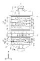
- the unit in one aspect of the invention comprises: having a housing containing a planetary gear mechanism; the housing has a passage through which coolant flows; the planetary gear mechanism having a ring gear fixed to the housing; The flow path has a portion that overlaps with the ring gear when viewed in the radial direction.
- heat exchange efficiency can be improved.
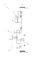
- FIG. 1 is a skeleton diagram explaining the unit.
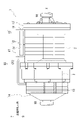
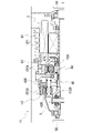
- FIG. 2 is an external view of the unit.
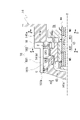
- FIG. 3 is a diagram illustrating the arrangement of units in a vehicle.
- FIG. 4 is a schematic cross-sectional view of the unit.
- FIG. 5 is an enlarged view around the differential case.
- FIG. 6 is an enlarged view around the ring gear.
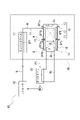
- FIG. 7 is a diagram illustrating a cooling water circulation system in the unit.
- FIG. 8 is a diagram for explaining cooling paths.
- FIG. 9 is a diagram for explaining cooling paths.
- FIG. 10 is a diagram explaining the rotation of the differential case.
- FIG. 11 is a diagram illustrating rotation of the differential case.
- FIG. 12 is a diagram for explaining the positional relationship between the vehicle compartment and the units.
- FIG. 13 is a diagram showing Modification 1.
- FIG. 14 is a diagram showing Modification 2.
- FIG. 15 is a diagram showing Modification 3.
- FIG. 13 is a diagram showing
- a “unit” is also called a “motor unit”, a “power transmission device”, or the like.
- a motor unit is a unit having at least a motor.
- a power transmission device is a device having at least a power transmission mechanism, and the power transmission mechanism is, for example, a gear mechanism and/or a differential gear mechanism.
- a unit that is a device comprising a motor and a power transmission belongs to the concept of both a motor unit and a power transmission.
- the “housing” contains the motor, gear, and inverter.
- a housing consists of one or more cases.
- "3 in 1” means a form in which a part of the motor case that houses the motor and a part of the inverter case that houses the inverter are integrally formed.
- the cover and the case constitute one case
- the case accommodating the motor and the case accommodating the inverter are integrally formed.
- a "motor” is a rotating electric machine that has a motor function and/or a generator function.
- a second element (part, portion, etc.) connected to the first element (part, portion, etc.); a second element (part, portion, etc.) connected downstream of the first element (part, portion, etc.);
- a second element (part, section, etc.) connected upstream of an element (part, section, etc.)
- the first element and the second element are power-transmittably connected.
- the power input side is upstream, and the power output side is downstream.
- the first element and the second element may be connected via another element (clutch, other gear mechanism, etc.).
- “Overlapping when viewed from a predetermined direction” means that a plurality of elements are arranged in a predetermined direction, and has the same meaning as “overlapping in a predetermined direction”.
- the "predetermined direction” is, for example, an axial direction, a radial direction, a gravitational direction, a vehicle running direction (vehicle forward direction, vehicle backward direction), or the like. If a drawing shows that multiple elements (parts, parts, etc.) are lined up in a predetermined direction, there is a sentence in the description explaining that they overlap when viewed in a predetermined direction. can be regarded as
- not overlapped when viewed from a predetermined direction and “offset when viewed from a predetermined direction” mean that a plurality of elements are not aligned in a predetermined direction, and "not overlapped in a predetermined direction”. , is synonymous with the description of "offset in a predetermined direction".
- the "predetermined direction” is, for example, an axial direction, a radial direction, a gravitational direction, a vehicle running direction (vehicle forward direction, vehicle backward direction), or the like. If a drawing shows that multiple elements (parts, parts, etc.) are not aligned in a predetermined direction, the description of the specification includes a sentence explaining that they do not overlap when viewed in a predetermined direction. can be regarded as
- the first element is located between the second element (part, portion, etc.) and the third element (part, portion, etc.) when viewed from a predetermined direction" In the case it means that the first element can be observed to be between the second and third elements.
- the "predetermined direction” includes an axial direction, a radial direction, a gravity direction, a vehicle running direction (vehicle forward direction, vehicle backward direction), and the like. For example, when the second element, the first element, and the third element are arranged in this order along the axial direction, the first element is between the second element and the third element when viewed in the radial direction.
- the drawing shows that the first element is between the second element and the third element when viewed from a predetermined direction
- the first element is the second element when viewed from a predetermined direction in the description of the specification. It can be considered that there is a sentence explaining what is between the third element.
- Axial direction means the axial direction of the rotation axis of the parts that make up the unit.
- Rotary direction means a direction perpendicular to the rotation axis of the parts that make up the unit.
- the parts are, for example, motors, gear mechanisms, differential gear mechanisms, and the like.
- a rotating element of a planetary gear mechanism (for example, a sun gear, a carrier, a ring gear, etc.) is "fixed" to another element, which means that it may be directly fixed or fixed via another member. good.
- the downstream side in the rotational direction means the downstream side in the rotational direction when the vehicle moves forward or the rotational direction when the vehicle moves backward. It is preferable to set it to the downstream side in the rotational direction when the vehicle moves forward, which occurs frequently.
- the downstream side in the rotational direction of the planetary gear mechanism means the downstream side in the revolution direction of the pinion gear.
- a "catch tank” is an element (part, part, etc.) that has the function of a tank (container) into which oil is introduced.
- the term “catch” refers to the fact that oil is supplied to the tank from the outside of the tank.
- the catch tank is provided, for example, using at least part of the housing, or is provided separately from the housing. Integrally forming the catch tank and the housing contributes to a reduction in the number of parts.
- Coolant is a refrigerant, for example, liquid (cooling water, etc.), gas (air, etc.), etc. Coolant is a concept that includes oil, but when both oil and coolant are used in this specification, it means that coolant is composed of a material different from that of oil.
- a "heat exchange section” is an element (part, section, etc.) that exchanges heat between two different heat exchange media.
- Combinations of two heat exchange media are, for example, oil and cooling water, cooling water and air, air and oil, and the like.
- a coolant flow passage formed in the housing as the heat exchange portion. This is because it can contribute to the reduction of the dimensions of the unit.
- the coolant flow path formed in the housing is a part integrally formed with the housing. For example, heat exchange between coolant and oil and/or air in the housing takes place through the walls of the housing.
- a "cabin” means a room in a vehicle where passengers board.
- FIG. 1 is a skeleton diagram for explaining the unit 1.
- FIG. FIG. 2 is an external view of the unit 1.
- FIG. FIG. 3 is a diagram illustrating the arrangement of the units 1 in the vehicle V. As shown in FIG. FIG. 3 shows a view of the vehicle V from the right side.
- FIG. 4 is a schematic cross-sectional view of the unit 1.
- FIG. FIG. 4 shows the state in which the inverter case is removed.
- FIG. 5 is an enlarged view around the differential case 50.
- FIG. FIG. 6 is an enlarged view around the ring gear 42.
- FIG. 7 is a diagram illustrating a circulation system 80 for cooling water W in the unit 1. As shown in FIG. FIG. FIG.
- FIG. 8 is a diagram illustrating the cooling paths CP1 and CP3.
- FIG. 8 shows a view from the same direction as FIG. In FIG. 8, the second case member 12 and the cover member 18 are indicated by broken lines, and the inverter case is omitted. In the enlarged view of FIG. 8, the regions of the protrusions 111c and 141b1, the thick portions 118 and 119, and the thick portions 143 and 144 are hatched.
- FIG. 9 is a diagram illustrating the cooling paths CP1 and CP3.
- FIG. 9 shows the unit of FIG. 2 viewed from above.
- the second case member 12 and the cover member 18 are indicated by dashed lines.
- 10A and 10B are diagrams for explaining the rotation of the differential case 50.
- FIG. 10 is a schematic diagram of the AA section of FIG. 11A and 11B are diagrams for explaining the rotation of the differential case 50.
- FIG. FIG. 11 is a schematic diagram of the BB section of FIG.
- FIG. 12 is a diagram for explaining the positional relationship between the vehicle interior VR and the unit 1.
- FIG. 12 is an enlarged view of area A in FIG. In FIG. 12, the areas where the cooling path CP3 and the ring gear 42 are provided are shown with cross-hatching of phantom lines. Also, the small diameter gear portion 432 is indicated by a dashed line.
- the unit 1 includes a motor 2, a power transmission mechanism 3 that transmits the power output by the motor 2 to drive wheels K, K of the vehicle, and an inverter IV (Fig. 2).
- the housing HS of the unit 1 is a "3 in 1" unit in which a portion of the motor case 10 that houses the motor 2 and an inverter case 17 that houses the inverter IV are integrally formed.
- the unit 1 includes a power transmission mechanism 3, a planetary reduction gear 4 (reduction gear mechanism, planetary gear mechanism), a differential mechanism 5 (differential gear mechanism), and an output shaft. It has a certain drive shaft 9 (9A, 9B).
- a planetary reduction gear 4 a differential mechanism 5, and a drive shaft 9 (9A, 9B) are provided along a transmission path for output rotation of the motor 2 around the rotation axis X.
- the axis of the drive shaft 9 ( 9 A, 9 B) is coaxial with the rotation axis X of the motor 2
- the differential mechanism 5 is coaxial with the motor 2 .
- the planetary reduction gear 4 is connected downstream of the motor 2 .
- a differential mechanism 5 is connected downstream of the motor 2 via a planetary reduction gear 4 .
- a drive shaft 9 ( 9 A, 9 B) is connected downstream of the differential mechanism 5 .
- the housing HS of the unit 1 is a 3-in-1 type housing and accommodates the motor 2, the power transmission mechanism 3 and the inverter IV.
- the housing HS is composed of one or more cases.
- the housing HS has, for example, a motor case 10 that houses the motor 2, a gear case 14 that houses the power transmission mechanism 3, and an inverter case 17 that houses the inverter IV.
- a gear case 14 is joined to one end side of the motor case 10 in the rotation axis X direction.
- An inverter case 17 is joined above the motor case 10 in the direction of the vertical line VL when the unit 1 is mounted on the vehicle.
- the inverter IV is an electronic component that includes a smoothing capacitor, power semiconductor element, driver board, etc.
- the inverter IV is electrically connected to the motor 2 inside the motor case 10 by wiring (not shown).
- the vehicle interior VR of the vehicle V is surrounded by a roof panel 71, a floor panel 72, and a dash panel 73.
- the unit 1 is provided on the front side of the vehicle compartment VR in the longitudinal direction of the vehicle, and is connected to the front wheels of the vehicle V.
- the drive shaft 9B is connected to the drive wheel K on the right side of the vehicle on the front side of the paper. Although illustration is omitted, the drive shaft 9A is connected to the driving wheel K on the left side of the vehicle on the back side of the paper surface.
- Battery B is arranged below floor panel 72 .
- the battery B is electrically connected to the inverter IV (see FIG. 2) in the inverter case 17 by wiring (not shown).
- Horizontal line HL2 passing through the top surface of inverter case 17 is located below horizontal line HL3 passing through floor panel 72 in the direction of vertical line VL.
- the motor 2 has a portion that overlaps the differential mechanism 5 (differential gear mechanism) when viewed in the axial direction (see FIG. 4).
- differential mechanism 5 differential gear mechanism
- “when viewed in the axial direction” means when viewed from the rotation axis X direction.
- the motor 2 has a portion that overlaps the planetary reduction gear 4 (reduction gear mechanism).
- the planetary reduction gear 4 (reduction gear mechanism) has a portion that overlaps the differential mechanism 5 (differential gear mechanism).
- the planetary reduction gear 4 (reduction gear mechanism) has a portion that overlaps the motor 2 .
- the differential mechanism 5 (differential gear mechanism) has a portion that overlaps the planetary reduction gear 4 (reduction gear mechanism).
- the differential mechanism 5 (differential gear mechanism) has a portion that overlaps the motor 2 when viewed in the axial direction.
- the motor 2 When viewed in the axial direction, the motor 2 has a portion that overlaps the differential mechanism 5 (differential gear mechanism).
- the motor case 10 includes a first case member 11, a second case member 12 fitted around the first case member 11, and a cover member 13 joined to one end of the first case member 11.
- the first case member 11 has a cylindrical support wall portion 111 and a flange-like joint portion 112 provided at one end 111 a of the support wall portion 111 .
- the support wall portion 111 is provided along the rotation axis X of the motor 2 .
- the motor 2 is accommodated inside the support wall portion 111 .
- the second case member 12 includes a cylindrical peripheral wall portion 121, a flange-shaped joint portion 122 provided at one end 121a of the peripheral wall portion 121, and a flange-shaped joint portion 123 provided at the other end 121b of the peripheral wall portion 121. and have The peripheral wall portion 121 of the second case member 12 is formed with an inner diameter that allows it to be externally inserted into the support wall portion 111 of the first case member 11 .
- the first case member 11 and the second case member 12 are assembled together by externally inserting the peripheral wall portion 121 of the second case member 12 into the supporting wall portion 111 of the first case member 11 .
- the joint portion 122 on the one end 121a side of the peripheral wall portion 121 abuts the joint portion 112 of the first case member 11 from the rotation axis X direction.
- These joints 122 and 112 are connected to each other by bolts (not shown).
- thick portions 118 and 119 are provided on the one end 111a side and the other end 111b side of the support wall portion 111 .
- the thick portions 118 and 119 protrude radially outward from the outer periphery of the support wall portion 111 .
- the radial thickness H2 of the thick portions 118 and 119 is greater than the radial thickness H1 of the support wall portion 111 (see FIG. 4).
- the thick portions 118 and 119 are provided over the entire circumference of the support wall portion 111 in the circumferential direction around the rotation axis X.
- Seal grooves 113 and 113 are opened in the outer peripheral surfaces of the thick portions 118 and 119, respectively.
- the seal grooves 113, 113 are provided along the circumferential direction around the rotation axis X, and are provided over the entire circumferential direction around the rotation axis X of the thick portions 118, 119, respectively.
- seal grooves 113, 113 are fitted with seal materials C, C. As shown in FIG. 4, these sealing materials C, C are pressed against the inner periphery of the peripheral wall portion 121 that is fitted over the support wall portion 111 to seal the gap between the outer periphery of the support wall portion 111 and the inner periphery of the peripheral wall portion 121. do.
- a projection 111c is provided on the outer circumference of the support wall portion 111 of the first case member 11. As shown in FIG. The protrusion 111c is provided in a region between the thick portions 118 and 119 in the rotation axis X direction.
- the radial thickness (protrusion height) of the projection 111 c in the radial direction of the rotation axis X is the same as the radial thickness H2 of the thick portions 118 and 119 .
- the protrusion 111c is one wall that extends in the circumferential direction around the rotation axis X and surrounds the rotation axis X with a space therebetween.
- the projection 111c is provided along the entire circumference of the support wall portion 111 along the circumferential direction around the rotation axis X.
- the protrusions 111c are provided with phase shifts in the circumferential direction around the rotation axis X, and are provided in a spiral shape in which the positions in the rotation axis X direction are different from the one end 111a side of the support wall portion 111 toward the other end 111b side. ing.
- the protrusion 111c When viewed in the radial direction, the protrusion 111c is provided along a straight line Lq1 inclined from a straight line Lp1 perpendicular to the rotation axis X. As shown in FIG. The angle ⁇ 1 formed by the straight lines Lp1 and Lq1 is the lead angle forming the spiral.
- the protrusion 111c is connected to the thick portion 118 via the connection wall 111d.
- the projection 111c is connected to the thick portion 119 via the connection wall 111e.
- the connection walls 111d and 111e are provided along the rotation axis X, respectively.
- the projection height (thickness) of the connection walls 111d and 111e in the radial direction of the rotation axis X is the same as the thickness H2 (see FIG. 8) of the projection 111c and the thick portions 118 and 119. As shown in FIG.
- the peripheral wall portion 121 of the second case member 12 is fitted over the support wall portion 111 of the first case member 11 (see broken lines in FIGS. 8 and 9).
- the peripheral wall portion 121 of the second case member 12 contacts the thick portions 118 and 119 of the support wall portion 111 of the first case member 11, the projection 111c, and the connection walls 111d and 111e.
- a spiral space is formed that continues from one end 111a of the support wall portion 111 toward the other end 111b.
- This spiral space forms a cooling passage CP1 through which cooling water W (see FIG. 7), which is a coolant, flows.
- the cooling water W exchanges heat with the motor 2 housed inside the support wall portion 111 via the support wall portion 111 .
- the spiral cooling path CP1 is simplified and shown in a straight line.
- the cooling passage CP1 has an inlet CP1a for the cooling water W at a portion surrounded by the projection 111c, the thick portion 118, and the connection wall 111d on the one end 111a side of the support wall portion 111.
- the cooling path CP1 has an outlet CP1b for the cooling water W at a portion surrounded by the protrusion 111c, the thick portion 119, and the connection wall 111e on the side of the other end 111b of the support wall portion 111.
- An inlet CP1a and an outlet CP1b of the cooling water W correspond to the start point and end point of the spiral space, respectively.
- one end of a pipe P1 is connected to an inlet CP1a of the cooling path CP1.
- the other end of the pipe P1 is connected to a cooling path CP2 of the inverter case 17, which will be described later.
- One end of the pipe P2 is connected to the outlet CP1b of the cooling path CP1.
- the other end of the pipe P2 is connected to a cooling path CP3 of the gear case 14, which will be described later.
- the pipes P1 and P2 are provided so as to pass through the peripheral wall portion 121 of the second case member 12, respectively.
- the other end 121b of the second case member 12 is provided with a wall portion 120 (cover) extending radially inward.
- the wall portion 120 is provided in a direction perpendicular to the rotation axis X.
- An opening 120a through which the drive shaft 9A is inserted is formed in a region of the wall portion 120 intersecting with the rotation axis X.
- a motor support portion 125 extending toward the motor 2 is provided on the surface of the wall portion 120 on the side of the motor 2 (right side in the figure).
- the motor support portion 125 has a tubular shape surrounding the opening 120a with a gap therebetween.
- the motor support portion 125 is inserted inside a coil end 253b, which will be described later.
- the motor support portion 125 faces the end portion 21b of the rotor core 21 with a gap in the rotation axis X direction.
- a bearing B ⁇ b>1 is supported on the inner circumference of the motor support portion 125 .
- the outer circumference of the motor shaft 20 is supported by a motor support portion 125 via a bearing B1.
- a cylindrical wall portion 126 extending toward the differential mechanism 5 is provided on the surface of the wall portion 120 on the side of the differential mechanism 5 (on the left side in the drawing).
- the tubular wall portion 126 has a tubular shape surrounding the opening 120a.
- a bearing B ⁇ b>2 is supported on the inner periphery of the cylindrical wall portion 126 .
- the bearing B2 supports a tubular wall portion 61 of the differential case 50, which will be described later.
- the cover member 13 has a wall portion 130 perpendicular to the rotation axis X and a joint portion 132 .
- the cover member 13 When viewed from the first case member 11, the cover member 13 is located on the side opposite to the differential mechanism 5 (on the right side in the drawing).
- the joint portion 132 of the cover member 13 is joined to the joint portion 112 of the first case member 11 from the rotation axis X direction.
- the cover member 13 and the first case member 11 are connected to each other with bolts (not shown). In this state, the cover member 13 closes the opening of the support wall portion 111 on the joint portion 112 side (right side in the figure) of the first case member 11 .
- an insertion hole 130a for the drive shaft 9A is provided in the central portion of the wall portion 130.
- a lip seal RS is provided on the inner circumference of the insertion hole 130a.
- the lip seal RS brings the lip portion (not shown) into elastic contact with the outer circumference of the drive shaft 9A.
- a gap between the inner periphery of the insertion hole 130a and the outer periphery of the drive shaft 9A is sealed with a lip seal RS.
- a peripheral wall portion 131 surrounding the insertion hole 130a is provided on the surface of the wall portion 130 on the side of the first case member 11 (left side in the figure).
- a drive shaft 9A is supported on the inner periphery of the peripheral wall portion 131 via a bearing B4.
- a motor support portion 135 and a connection wall 136 are provided on the inner diameter side of the joint portion 132 .
- the motor support portion 135 is provided on the motor 2 side (left side in the figure) when viewed from the peripheral wall portion 131 .
- the motor support portion 135 has a tubular shape surrounding the rotation axis X with a space therebetween.
- a cylindrical connection wall 136 is connected to the outer periphery of the motor support portion 135 .
- the connection wall 136 is formed with a larger outer diameter than the peripheral wall portion 131 on the wall portion 130 side (right side in the drawing).
- the connection wall 136 is oriented along the rotation axis X and extends away from the motor 2 .
- the connection wall 136 connects the motor support portion 135 and the joint portion 132 .
- One end 20a side of the motor shaft 20 penetrates the inside of the motor support portion 135 from the motor 2 side to the peripheral wall portion 131 side.
- a bearing B ⁇ b>1 is supported on the inner periphery of the motor support portion 135 .
- the outer circumference of the motor shaft 20 is supported by a motor support portion 135 via a bearing B1.
- a lip seal RS is provided at a position adjacent to the bearing B1.
- Oil holes 136 a and 136 b are opened on the inner periphery of the connection wall 136 .
- the oil OL flows into the space (internal space Sc) surrounded by the connection wall 136 through the oil hole 136a.
- the oil OL that has flowed into the internal space Sc is discharged from the oil hole 136b.
- the lip seal RS is provided to prevent the oil OL in the connection wall 136 from flowing into the motor 2 side.
- the gear case 14 has a peripheral wall portion 141 and a flange-like joint portion 142 provided at the end of the peripheral wall portion 141 on the motor case 10 side.
- a support portion 145 for a bearing B2 which will be described later, is provided at an end portion of the peripheral wall portion 141 opposite to the joint portion 142 (on the left side in the drawing).
- the peripheral wall portion 141 includes a cylindrical wall portion 141a connected to the joint portion 142, an inclined portion 141c (inclined surface) connected to the support portion 145, and a connecting wall portion 141b connecting the cylindrical wall portion 141a and the inclined portion 141c.
- the tubular wall portion 141a and the connecting wall portion 141b are gradually reduced in diameter from the joint portion 142 and connected to the inclined portion 141c.
- the inclined portion 141c is inclined such that the inner diameter decreases from the connection wall portion 141b toward the support portion 145 .
- the planetary reduction gear 4 and the differential mechanism 5 which are the power transmission mechanism 3 are accommodated inside the peripheral wall portion 141 .
- the cylinder wall portion 141a and the connection wall portion 141b of the gear case 14 are provided along the rotation axis X, respectively.
- the outer diameter of the tubular wall portion 141a is larger than the outer diameter of the connecting wall portion 141b.
- a boundary between the cylinder wall portion 141a and the connection wall portion 141b in the rotation axis X direction is a stepped surface 16 perpendicular to the rotation axis X.
- a cover member 18 is fitted around the gear case 14 .
- the cover member 18 has a cylindrical peripheral wall portion 181 and a flange-like joint portion 182 provided at one end 181 a of the peripheral wall portion 181 .
- a peripheral wall portion 181 of the cover member 18 is formed with an inner diameter that allows it to be externally inserted into the connection wall portion 141 b of the gear case 14 .
- the gear case 14 and the cover member 18 are assembled together by externally inserting the peripheral wall portion 181 of the cover member 18 into the connection wall portion 141 b of the gear case 14 .
- the joint portion 182 of the cover member 18 is joined to the step surface 16 of the gear case 14 from the rotation axis X direction.
- the gear case 14 and the cover member 18 are connected to each other with bolts (not shown).
- a thick portion 143 is provided at the end of the connecting wall portion 141b on the cylinder wall portion 141a side.
- a thick portion 144 is provided at the end of the connecting wall portion 141b on the inclined portion 141c side.
- the thick portions 143 and 144 protrude radially outward from the outer circumference of the connection wall portion 141b.
- a radial thickness H4 of the thick portions 143 and 144 is larger than a radial thickness H3 (see FIG. 6) of the connecting wall portion 141b.
- the thick portions 143 and 144 are provided over the entire circumference of the connection wall portion 141b in the circumferential direction around the rotation axis X.
- Seal grooves 146 and 146 are opened in the outer peripheral surfaces of the thick portions 143 and 144, respectively.
- the seal grooves 146, 146 are provided along the circumferential direction around the rotation axis X, and are provided over the entire circumferential direction around the rotation axis X of the thick portions 143, 144, respectively.
- the seal grooves 146, 146 are fitted with sealing materials C, C. These sealing materials C, C are pressed against the inner periphery of the peripheral wall portion 181 that is fitted onto the connecting wall portion 141b to seal the gap between the outer periphery of the connecting wall portion 141b and the inner periphery of the peripheral wall portion 181. do.
- a projection 141b1 is provided on the outer periphery of the connection wall portion 141b of the gear case 14. As shown in FIG. The protrusion 141b1 is provided in a region between the thick portions 143 and 144 in the rotation axis X direction. The radial thickness (protrusion height) of the protrusion 141b1 in the radial direction of the rotation axis X is the same as the radial thickness H4 of the thick portions 143 and 144 .
- the protrusion 141b1 is one wall that extends in the circumferential direction around the rotation axis X and surrounds the rotation axis X at intervals.
- the projection 141b1 is provided along the circumferential direction around the rotation axis X over the entire circumference of the connection wall portion 141b.
- the projections 141b1 are provided with phase shifts in the circumferential direction around the rotation axis X, and are provided in a spiral shape in which the positions in the rotation axis X direction are different from the cylindrical wall portion 141a side toward the inclined portion 141c side.
- the projection 141b1 When viewed in the radial direction, the projection 141b1 is provided along a straight line Lq2 inclined from a straight line Lp2 perpendicular to the rotation axis X. As shown in FIG. The angle ⁇ 2 formed by the straight lines Lp2 and Lq2 is the lead angle forming the spiral.
- connection wall portion 141a side of the connection wall portion 141b On the cylinder wall portion 141a side of the connection wall portion 141b, the projection 141b1 is connected to the thick portion 143 via the connection wall 141f. On the inclined portion 141c side of the connection wall portion 141b, the protrusion 141b1 is connected to the thick portion 144 via the connection wall 141g.
- the connection walls 141f and 141g are provided along the rotation axis X, respectively.
- the projection height (thickness) of the connection walls 141f and 141g in the radial direction of the rotation axis X is the same as the thickness H4 (see FIG. 8) of the projection 141b1 and the thick portions 143 and 144. As shown in FIG.
- the peripheral wall portion 181 of the cover member 18 is fitted onto the connection wall portion 141b of the gear case 14 (see broken lines in FIGS. 8 and 9).
- the peripheral wall portion 181 of the cover member 18 abuts on the thick portions 143 and 144 of the connection wall portion 141b of the gear case 14, the projection 141b1, and the connection walls 141f and 141g.
- a spiral space is formed between the peripheral wall portion 181 and the connecting wall portion 141b, continuing from the cylinder wall portion 141a side toward the inclined portion 141c side.
- This spiral space forms a cooling passage CP3 through which cooling water W (see FIG. 7), which is a coolant, flows.
- the cooling water W exchanges heat with the planetary reduction gear 4 (see FIG. 4) accommodated inside the connecting wall portion 141b through the connecting wall portion 141b.
- the spiral cooling path CP3 is simplified and shown in a straight line.
- the cooling passage CP3 has an inlet CP3a for the cooling water W at a portion surrounded by the protrusion 141b1, the thick portion 143, and the connection wall 141f on the cylindrical wall portion 141a side.
- the cooling path CP3 has an outlet CP3b for the cooling water W at a portion surrounded by the protrusion 141b1, the thick portion 144, and the connection wall 141g on the inclined portion 141c side.
- An inlet CP3a and an outlet CP3b of the cooling water W correspond to the start point and end point of the spiral space, respectively.
- the inlet CP3a of the cooling path CP3 is connected to the other end of the pipe P2.
- One end of the pipe P2 is connected to the outlet CP1b of the cooling path CP1 of the motor case 10 described above.
- One end of the pipe P3 is connected to the outlet CP3b of the cooling path CP3.
- the other end of the pipe P3 is connected to an oil cooler 83, which will be described later.
- the pipes P2 and P3 are provided so as to pass through the peripheral wall portion 181 of the cover member 18, respectively.
- the gear case 14 is positioned on the differential mechanism 5 side (left side in the drawing) when viewed from the motor case 10 .
- the joint portion 142 of the gear case 14 is joined to the joint portion 123 of the second case member 12 of the motor case 10 from the rotation axis X direction.
- the gear case 14 and the second case member 12 are connected to each other by bolts (not shown).
- a mating surface T between the joint portion 142 of the gear case 14 and the joint portion 123 of the second case member 12 is orthogonal to the rotation axis X.
- the cooling paths CP1 and CP3 extend along the rotation axis X in directions away from the mating surface T.
- the space formed inside the joined motor case 10 and gear case 14 is partitioned into two by the wall portion 120 (cover) of the second case member 12 .
- the motor case 10 side of the wall portion 120 is a motor chamber Sa that houses the motor 2
- the gear case 14 side of the wall portion 120 is a gear chamber Sb that houses the planetary reduction gear 4 and the differential mechanism 5 .
- a wall portion 120 as a cover is sandwiched between the motor 2 and the differential mechanism 5 inside the housing HS.
- the cover here may have a portion housed within the housing HS, and like the wall portion 120, the entire cover may be housed in the housing HS. Also, the cover may be separate from the second case member 12, for example. In this case, the cover may be sandwiched between the motor case 10 and the gear case 14 and fixed. A part of the cover may be exposed outside the housing HS.
- the motor 2 has a cylindrical motor shaft 20, a cylindrical rotor core 21 fitted onto the motor shaft 20, and a stator core 25 surrounding the outer periphery of the rotor core 21 with a space therebetween. .
- bearings B ⁇ b>1 and B ⁇ b>1 are externally inserted and fixed on both sides of the rotor core 21 .
- a bearing B ⁇ b>1 positioned on the one end 20 a side (right side in the drawing) of the motor shaft 20 when viewed from the rotor core 21 is supported on the inner periphery of the motor support portion 135 of the cover member 13 .
- a bearing B ⁇ b>1 located on the other end 20 b side (left side in the drawing) is supported on the inner circumference of a cylindrical motor support portion 125 of the second case member 12 .
- the motor support portions 135, 125 are arranged on the inner diameter side of coil ends 253a, 253b, which will be described later.
- the motor support portions 135 and 125 are arranged to face one end portion 21a and the other end portion 21b of the rotor core 21 with a gap in the rotation axis X direction.
- the rotor core 21 is formed by laminating a plurality of silicon steel plates. Each of the silicon steel plates is fitted over the motor shaft 20 in a state where relative rotation with the motor shaft 20 is restricted.
- the silicon steel plate has a ring shape when viewed from the rotation axis X direction of the motor shaft 20 .
- N-pole and S-pole magnets are provided alternately in the circumferential direction around the rotation axis X on the outer peripheral side of the silicon steel plate.
- a stator core 25 surrounding the outer periphery of the rotor core 21 is formed by laminating a plurality of electromagnetic steel sheets.
- the stator core 25 is fixed to the inner periphery of the cylindrical support wall portion 111 of the first case member 11 .
- Each of the electromagnetic steel sheets has a ring-shaped yoke portion 251 fixed to the inner periphery of the support wall portion 111 and tooth portions 252 protruding from the inner periphery of the yoke portion 251 toward the rotor core 21 side.
- stator core 25 having a configuration in which the windings 253 are distributed over a plurality of teeth 252 is adopted.
- the stator core 25 is longer than the rotor core 21 in the direction of the rotation axis X by the coil ends 253a and 253b projecting in the direction of the rotation axis X. As shown in FIG.
- a stator core in which windings are concentratedly wound may be employed for each of the plurality of tooth portions 252 protruding toward the rotor core 21 side.
- the wall portion 120 (motor support portion 125) of the second case member 12 is provided with an opening 120a.
- the other end 20b side of the motor shaft 20 passes through the opening 120a to the differential mechanism 5 side (left side in the figure) and is positioned inside the gear case 14 .
- the other end 20b of the motor shaft 20 faces a side gear 54A, which will be described later, with a gap in the rotation axis X direction.
- a lip seal RS is inserted between the motor shaft 20 and the opening 120 a of the wall portion 120 .
- Oil OL for lubricating the planetary reduction gear 4 and the differential mechanism 5 is enclosed in the inner diameter side of the gear case 14 .
- Lip seal RS is provided to prevent oil OL in gear case 14 from flowing into motor case 10 .
- the sun gear 41 of the planetary reduction gear 4 is spline-fitted to the region of the motor shaft 20 located within the gear case 14 .
- a toothed portion 41a is formed on the outer periphery of the sun gear 41, and a large-diameter gear portion 431 of the stepped pinion gear 43 is meshed with the toothed portion 41a.
- the stepped pinion gear 43 has a large-diameter gear portion 431 (large pinion) that meshes with the sun gear 41 and a small-diameter gear portion 432 (small pinion) having a smaller diameter than the large-diameter gear portion 431 .
- the large-diameter gear portion 431 and the small-diameter gear portion 432 are integral gear components arranged side by side in the direction of the axis X1 parallel to the rotation axis X. As shown in FIG.
- the pinion shaft 44 passes through the inner diameter side of the large-diameter gear portion 431 and the small-diameter gear portion 432 .
- the stepped pinion gear 43 is rotatably supported on the outer circumference of the pinion shaft 44 via needle bearings NB, NB.
- a tooth portion 432 a of the small diameter gear portion 432 meshes with the inner peripheral teeth 422 of the ring gear 42 .
- the ring gear 42 has a ring shape surrounding the rotation axis X with a space therebetween.
- a plurality of engaging teeth 421 projecting radially outward are provided on the outer periphery of the ring gear 42 .
- the plurality of engaging teeth 421 are provided circumferentially around the rotation axis X at intervals.
- Engaging teeth 421 provided on the outer periphery of the ring gear 42 are spline-fitted to tooth portions 146a provided on the inner periphery of the connection wall portion 141b. As a result, the rotation of the ring gear 42 around the rotation axis X is restricted.
- the differential mechanism 5 has a differential case 50 (differential case) as an input element, a drive shaft (output shaft) as an output element, and a differential gear set as a differential element.
- the differential case 50 may be composed of two case members assembled in the rotation axis X direction.
- the differential case 50 also functions as a carrier that supports the stepped pinion gear 43 of the planetary reduction gear 4.
- the stepped pinion gear 43 is rotatably supported by the differential case 50 via the pinion shaft 44 .
- the three stepped pinion gears 43 are circumferentially spaced around the rotation axis X. As shown in FIG.
- a pinion mate gear 52 which is a bevel gear type differential gear, and side gears 54A and 54B are provided as a differential gear set.
- the pinion mate gear 52 is supported by the pinion mate shaft 51 .
- the pinion mate shaft 51 has a central member 510 arranged on the rotation axis X and a shaft member 511 connected to the outer diameter side of the central member 510 .
- a plurality of shaft members 511 are provided in the circumferential direction around the rotation axis X at equal intervals.
- the shaft member 511 is inserted through a radially extending support hole 69 of the differential case 50 and supported.
- the pinion mate gears 52 are fitted one by one onto each of the shaft members 511 and are rotatably supported.
- the side gear 54A is positioned on one side of the central member 510 in the rotation axis X direction, and the side gear 54B is positioned on the other side.
- the side gears 54A, 54B are rotatably supported by the differential case 50, respectively.
- the side gear 54A meshes with the pinion mate gear 52 from one side in the rotation axis X direction.
- the side gear 54B meshes with the pinion mate gear 52 from the other side in the rotation axis X direction.
- An opening 60 and a cylindrical wall portion 61 surrounding the opening 60 are provided in the central portion of one end side (right side in the drawing) of the differential case 50 .
- the cylindrical wall portion 61 extends toward the motor case 10 side.
- the outer circumference of the cylinder wall portion 61 is supported by the wall portion 120 of the second case member 12 via the bearing B2.
- the drive shaft 9A is inserted through the opening 60 from the rotation axis X direction.
- the drive shaft 9A passes through the insertion hole 130a of the wall portion 130 of the cover member 13, and extends through the inner diameter side of the motor shaft 20 of the motor 2 and the sun gear 41 (see FIG. 5) of the planetary reduction gear 4. are provided across the rotation axis X direction.
- a through hole 65 and a cylindrical wall portion 66 surrounding the through hole 65 are formed in the center of the other end side (left side in the drawing) of the differential case 50 .
- a bearing B ⁇ b>2 is fitted on the cylindrical wall portion 66 .
- the bearing B ⁇ b>2 externally inserted into the cylinder wall portion 66 is held by the support portion 145 of the gear case 14 .
- a tubular wall portion 66 of the differential case 50 is rotatably supported by the gear case 14 via a bearing B2.
- the drive shaft 9B passing through the opening 145a of the gear case 14 is inserted into the support portion 145 from the rotation axis X direction.
- the drive shaft 9B is rotatably supported by a support portion 145.
- the cylinder wall portion 66 functions as a shaft support portion that supports the outer circumference of the drive shaft 9B.
- a lip seal RS is fixed to the inner circumference of the opening 145a.
- a lip portion (not shown) of the lip seal RS is in elastic contact with the outer circumference of the cylinder wall portion 540 of the side gear 54B externally fitted on the drive shaft 9B. As a result, the gap between the outer circumference of the cylindrical wall portion 540 of the side gear 54B and the inner circumference of the opening 145a is sealed.
- the tip portions of the drive shafts 9 (9A, 9B) face each other with a gap in the rotation axis X direction.
- Side gears 54A and 54B supported by a differential case 50 are spline-fitted to the outer circumferences of the tip portions of the drive shafts 9 (9A and 9B), respectively.
- the side gears 54A, 54B and the drive shaft 9 (9A, 9B) are connected to each other so as to rotate about the rotation axis X together.
- the side gears 54A and 54B are arranged opposite to each other with a gap in the rotation axis X direction.
- a central member 510 of the pinion mate shaft 51 is positioned between the side gears 54A, 54B.
- the pinion mate gear 52 of the pinion mate shaft 51 is assembled to a side gear 54A positioned on one side in the direction of the rotation axis X and a side gear 54B positioned on the other side in a state in which the teeth thereof are meshed with each other.
- a support hole 62 on the one end 44a side of the pinion shaft 44 is formed on the outer diameter side of the opening 60 on the one end side (right side in the drawing) of the differential case 50 .
- a support hole 68 on the side of the other end 44b of the pinion shaft 44 is formed in the other end side of the differential case 50 (left side in the drawing).
- the support holes 62 and 68 are formed at overlapping positions in the rotation axis X direction.
- the support holes 62 and 68 are formed at intervals in the circumferential direction around the rotation axis X so as to match the position where the stepped pinion gear 43 is arranged.
- One end 44 a of the pinion shaft 44 is inserted into the support hole 62 and the other end 44 b is inserted into the support hole 68 .
- the other end 44 b of the pinion shaft 44 is press-fitted into the support hole 68 so that the pinion shaft 44 is fixed to the differential case 50 so as not to rotate relative to it.
- a stepped pinion gear 43 externally fitted on the pinion shaft 44 is rotatably supported around an axis X1 parallel to the rotation axis X. As shown in FIG.
- lubricating oil OL is stored inside the gear case 14 .
- the differential case 50 rotates around the rotation axis X, the oil OL is scraped up by the differential case 50 .
- the differential case 50, the pinion shaft 44, and the like are provided with oil passages, oil holes, and the like for introducing oil that has been raked up by the differential case 50. As shown in FIG. This makes it easier for the oil OL to be introduced into rotating members such as the bearing B2 and the needle bearing NB (see FIG. 6).
- a catch tank 15 is provided above the space that accommodates the differential case 50 inside the gear case 14 .
- the catch tank 15 is positioned on one side (right side in the drawing) of a vertical line VL perpendicular to the rotation axis X. As shown in FIG.
- the catch tank 15 communicates with the gear chamber Sb through the communication port 150 .
- the oil OL that has been scraped up and scattered by the differential case 50 flows into the catch tank 15 and is collected.
- the toothed portion 432 a of the small-diameter gear portion 432 meshes with the inner peripheral teeth 422 of the ring gear 42 fixed to the inner periphery of the gear case 14 .
- the small diameter gear portion 432 rotates counterclockwise around the axis X1 as shown in FIG. While rotating, it revolves around the rotation axis X in the clockwise direction CW.
- the differential case 50 rotates around the rotation axis X in the clockwise direction CW.
- the catch tank 15 is positioned on the right side of the vertical line VL, that is, on the downstream side in the rotational direction of the differential case 50 .
- the catch tank 15 is connected to an oil cooler 83 (see FIG. 7) via an oil passage, piping, etc. (not shown).
- the oil cooler 83 is connected to an oil hole 136a (see FIG. 4) formed in the connection wall 136 via a pipe, an oil passage and the like (not shown).
- the peripheral wall portion 141 of the gear case 14 is formed with an oil hole Ha.
- the oil hole Ha is connected via a pipe (not shown) to an oil hole 136b formed in the internal space Sc.
- the oil OL discharged from the internal space Sc through the oil hole 136b is re-supplied into the gear chamber Sb through the oil hole Ha.
- the tooth portion 432a of the small diameter gear portion 432 meshes with the inner peripheral tooth 422 of the ring gear 42 on the outer diameter side.
- the engagement teeth 421 of the ring gear 42 are spline-fitted to teeth 146a provided on the inner periphery of the connection wall 141b.
- a peripheral wall portion 181 of the cover member 18 is fitted onto the connection wall portion 141b.
- a cooling path CP3 is interposed between the connection wall portion 141b and the peripheral wall portion 181 in the radial direction of the rotation axis X.
- the cooling path CP3 surrounds the connection wall portion 141b over the entire circumference in the circumferential direction around the rotation axis X.
- a meshing portion between the tooth portion 432a of the small-diameter gear portion 432 and the inner circumferential tooth 422 of the ring gear 42 overlaps the cooling path CP3 in the radial direction of the rotation axis X. As shown in FIG.
- a virtual circle Im which is a revolution locus drawn by the outermost circumference of the large-diameter gear portion 431 (see the broken line in the drawing), has a smaller diameter than the inner diameter R3 of the peripheral wall portion 181, and the connection wall It has a diameter R2 larger than the outer diameter R1 of the portion 141b (R1 ⁇ R2 ⁇ R3).
- the cooling path CP3 when viewed from the radial direction of the rotation axis X, overlaps the large diameter gear portion 431 in the rotation axis X direction. In addition, when viewed from the radial direction of the rotation axis X, the cooling path CP3 has a portion offset from the ring gear 42 toward the inclined portion 141c in the rotation axis X direction.
- the unit 1 is provided with a cooling water W circulation system 80 .
- the circulation system 80 circulates the cooling water W between the cooling path CP ⁇ b>1 of the motor case 10 , the cooling path CP ⁇ b>2 of the inverter case 17 and the cooling path CP ⁇ b>3 of the gear case 14 .
- the circulation system 80 further includes an oil cooler 83, a water pump WP, and a radiator 82 between the cooling paths CP3 and CP2, which are connected by pipes or the like through which cooling water W flows.
- the water pump WP pumps cooling water W through the circulation system 80 .
- the radiator 82 is a device that dissipates the heat of the cooling water W and cools it.
- the oil cooler 83 is a heat exchanger that exchanges heat between the cooling water W and the oil OL.
- the cooling water W pressure-fed to the water pump WP flows through the cooling path CP2 in the inverter case 17, then passes through the cooling path CP1 in the motor case 10 and the cooling path CP3 in the gear case 14, and then flows through the oil cooler 83. supplied to The oil cooler 83 cools the oil OL by exchanging heat between the cooling water W and the oil OL.
- the cooling water W flowing through the oil cooler 83 is cooled by the radiator 82 and then supplied to the cooling path CP2 of the inverter case 17 again.
- the cooling path CP1 is connected to the pipe P1 at the inlet CP1a.
- the pipe P ⁇ b>1 is also connected to the cooling path CP ⁇ b>2 of the inverter case 17 .
- the cooling path CP1 is connected to a pipe P2 passing through the second case member 12 at an outlet CP1b.
- the pipe P2 passes through the cover member 18 and is also connected to the cooling path CP3.
- the cooling path CP3 is connected to the pipe P2 at an inlet CP3a.
- the cooling path CP3 is connected to a pipe P3 passing through the cover member 18 at an outlet CP3b.
- the pipe P3 is also connected to the oil cooler 83 .
- the cooling water W discharged from the cooling path CP2 of the inverter case 17 is supplied to the inlet CP1a of the cooling path CP1 through the pipe P1.
- the cooling water W spirally moves inside the motor case 10 from the inlet CP1a toward the outlet CP1b.
- the cooling water W cools the motor 2 in the course of moving spirally in the motor case 10 .
- the cooling water W that has reached the outlet CP1b of the cooling path CP1 is discharged from the pipe P2 to the cooling path CP3.
- the cooling water W moves spirally around the outer periphery of the gear case 14 from the inlet CP3a toward the outlet CP3b.
- the cooling water W cools the surroundings of the ring gear 42 in the process of spirally moving around the outer periphery of the gear case 14 .
- the cooling water W that has reached the outlet CP3b of the cooling path CP3 is discharged to the oil cooler 83 through the pipe P3.
- a planetary reduction gear 4 As shown in FIG. 1, in the unit 1, a planetary reduction gear 4, a differential mechanism 5, and drive shafts 9A and 9B are provided along the output rotation transmission path of the motor 2. As shown in FIG. 1, a planetary reduction gear 4, a differential mechanism 5, and drive shafts 9A and 9B are provided along the output rotation transmission path of the motor 2. As shown in FIG. 1, a planetary reduction gear 4, a differential mechanism 5, and drive shafts 9A and 9B are provided along the output rotation transmission path of the motor 2. As shown in FIG.
- the sun gear 41 serves as an input portion for the output rotation of the motor 2
- the differential case 50 that supports the stepped pinion gear 43 serves as an output portion for the input rotation.
- the stepped pinion gear 43 (the large-diameter gear portion 431 and the small-diameter gear portion 432) rotates according to the rotation input from the sun gear 41 side. , and rotates around the axis X1.
- the small diameter gear portion 432 of the stepped pinion gear 43 meshes with the ring gear 42 fixed to the inner circumference of the gear case 14 . Therefore, the stepped pinion gear 43 revolves around the rotation axis X while rotating around the axis X1.
- the outer diameter of the small-diameter gear portion 432 is smaller than the outer diameter of the large-diameter gear portion 431 .
- the differential case 50 supporting the stepped pinion gear 43 rotates around the rotation axis X at a rotation speed lower than the rotation input from the motor 2 side. Therefore, the rotation input to the sun gear 41 of the planetary reduction gear 4 is greatly reduced by the stepped pinion gear 43 and then output to the differential case 50 (differential mechanism 5).
- Lubricating oil OL is stored in the gear chamber Sb.
- the oil OL stored in the gear chamber Sb is raked up by the differential case 50 rotating around the rotation axis X.
- the raking oil OL forms a meshing portion between the sun gear 41 and the large diameter gear portion 431, a meshing portion between the small diameter gear portion 432 and the ring gear 42, and a meshing portion between the pinion mate gear 52 and the side gears 54A and 54B. is lubricated.
- the differential case 50 rotates about the rotation axis X in the clockwise direction CW.
- a catch tank 15 is provided above the gear case 14 .
- the catch tank 15 is located downstream of the differential case 50 in the rotation direction, and part of the oil OL that has been scraped up by the differential case 50 flows into the catch tank 15 .
- the oil OL that has flowed into the catch tank 15 is introduced into an oil cooler 83 (see FIG. 7) through a pipe (not shown) and cooled.
- the cooled oil OL is supplied to the internal space Sc formed in the connecting wall 136 via the oil hole 136a.
- the oil OL supplied to the internal space Sc lubricates the bearing B4 and is discharged from the oil hole 136b.
- the oil OL discharged from the oil hole 136b is supplied from the oil hole Ha into the gear chamber Sb via a pipe (not shown).
- the small diameter gear portion 432 revolves around the rotation axis X by rotating around the axis X1 while meshing the tooth portion 432a with the inner peripheral teeth 422 of the ring gear 42.
- the temperature of the small-diameter gear portion 432 and the ring gear 42 increases due to frictional heat generated when the tooth portion 432a and the inner circumferential tooth 422 mesh with each other.
- the small-diameter gear portion 432 revolves around the rotation axis X, it is cooled by periodically passing through the oil OL accumulated in the lower portion of the gear chamber Sb.
- the ring gear 42 has an engaging tooth 421 provided on the outer periphery spline-fitted to a toothed portion 146a provided on the inner periphery of the connection wall portion 141b, and rotation about the rotation axis X is restricted. Therefore, the ring gear 42 is more difficult to obtain the cooling effect of the oil OL than the small-diameter gear portion 432, so the temperature of the ring gear 42 is likely to rise. The heat of the ring gear 42 is transferred from the tooth portion 146a to the connection wall portion 141b.
- the cooling path CP3 is positioned on the outer peripheral side of the connection wall portion 141b.
- the ring gear 42, the connection wall portion 141b, and the cooling path CP3 overlap in the radial direction of the rotation axis X. As shown in FIG. Therefore, the ring gear 42 can exchange heat with the cooling water W flowing through the cooling path CP3 via the connection wall portion 141b.
- the ring gear 42 is cooled by the heat exchange of the cooling water W in the cooling path CP3.
- a meshing noise N is generated.
- the meshing noise N radially propagates from the ring gear 42 to the outside in the radial direction of the rotation axis X.
- a portion of the meshing noise N reaches the inside of the vehicle interior VR.
- the meshing sound N is perceived by the occupants of the vehicle V as sound leakage (noise).
- cooling path CP3 surrounds the ring gear 42 along the entire circumference in the circumferential direction around the rotation axis X. Also, the unit 1 having the cooling path CP3 is separated from the vehicle interior VR by the floor panel 72 and the dash panel 73 . That is, cooling path CP3 has a portion sandwiched between vehicle interior VR and ring gear 42 .
- the meshing noise N traverses the cooling path CP3 from the radially inner diameter side to the outer diameter side when propagating radially outward of the rotation axis X.
- the cooling water W in the cooling path CP3 functions as a shield that shields the meshing noise N from propagating. As a result, it is possible to reduce the meshing noise N from reaching the vehicle interior VR.
- the cooling path CP3 surrounds the ring gear 42 over the entire circumference in the circumferential direction around the rotation axis X. That is, the cooling path CP3 has a portion positioned above the horizontal line HL1 passing through the rotation axis X. As shown in FIG. 12, the cooling path CP3 surrounds the ring gear 42 over the entire circumference in the circumferential direction around the rotation axis X. That is, the cooling path CP3 has a portion positioned above the horizontal line HL1 passing through the rotation axis X. As shown in FIG.
- the unit 1 is provided below the vehicle interior VR in the direction of the vertical line VL.
- the horizontal line HL2 passing through the top surface of the inverter case 17 is arranged below the horizontal line HL3 passing through the floor panel 72 in the direction of the vertical line VL. That is, the cooling path CP3 has a portion sandwiched between the vehicle interior VR and the ring gear 42 in the direction of the vertical line VL.
- the projection 141b1 forming the cooling path CP3 is provided along the circumferential direction around the rotation axis X over the entire circumference of the connection wall portion 141b.
- the protrusion 141b1 is provided in a helical shape such that the position in the direction of the rotation axis X changes from the cylinder wall portion 141a side toward the inclined portion 141c side.
- a centrifugal force due to the revolution of the small-diameter gear portion 432 acts on the ring gear 42 and the connection wall portion 141b that supports the ring gear 42 . Due to the centrifugal force, a stress spreading outward in the radial direction of the rotation axis X is generated in the connection wall portion 141b.
- the projection 141b1 functions as a rib. Thereby, the rigidity of the connection wall portion 141b against the stress extending radially outward of the rotation axis X can be increased.
- By increasing the rigidity of the connection wall portion 141b deformation of the gear case 14 can be reduced.
- the volume of the region supporting the ring gear 42 in the connection wall portion 141b can be increased (increased thickness) by providing the protrusion 141b1.
- the mesh noise N shielding function of the gear case 14 itself is also improved.
- the protrusion 141b1 when the protrusion 141b1 is provided at a position that overlaps the ring gear 42 in the radial direction of the rotation axis X, the protrusion 141b1 is provided at a position offset from the ring gear 42 in the rotation axis X direction. , the effect of shielding the meshing noise N is improved.
- the unit 1 is connected to the front wheels of the vehicle V, and is arranged in front of the vehicle compartment VR in the longitudinal direction of the vehicle. As shown in FIG. 12, when the vehicle V travels forward, the unit 1 receives travel wind Air from the front of the vehicle. In this case, a region of the unit 1 on the front side of the vehicle with respect to the vertical line VL passing through the rotation axis X receives a large amount of running wind Air. A region of the gear case 14 on the front side of the vehicle with respect to the vertical line VL passing through the rotation axis X also receives a large amount of running wind Air. Most of the running wind Air received on the vehicle front side of the gear case 14 passes through the area below the horizontal line HL1 and escapes to the vehicle rear side.
- the cooling path CP3 surrounds the entire circumference of the ring gear 42 in the circumferential direction around the rotation axis X. As shown in FIG. That is, the cooling path CP3 has a portion radially offset from the ring gear 42 on the opposite side of the vehicle compartment VR in the vehicle longitudinal direction (vehicle front side of the vertical line VL). Further, the cooling path CP3 has a portion radially offset from the ring gear 42 below the horizontal line HL1 in the vertical line VL direction.
- the cooling water W flowing through the cooling path CP3 is cooled by heat exchange with the running wind Air in a region on the vehicle front side of the vertical line VL and a region below the horizontal line HL1.
- the unit 1 according to the present embodiment can cool the cooling water W by using the running wind Air when passing through the cooling path CP3, so that the cooling efficiency of the cooling water W is is improving. Therefore, the unit 1 can be effectively cooled even with a small amount of cooling water W. Since the total amount of cooling water W used in the unit 1 can be reduced while maintaining the cooling efficiency, the weight of the unit 1 can be reduced.
- the unit 1 has a housing HS that accommodates the planetary reduction gear 4 (planetary gear mechanism).
- the housing HS has a cooling path CP3 (flow path) through which cooling water W (coolant) flows.
- the planetary reduction gear 4 has a ring gear 42 fixed to the housing HS.
- the cooling path CP3 When viewed from the radial direction of the rotation axis X of the planetary reduction gear 4 (when viewed in the radial direction), the cooling path CP3 has a portion that overlaps the ring gear 42 .
- the space around the ring gear 42 can be utilized to dispose the cooling path CP3.
- This increases the contact area between the housing HS and the cooling water W, thereby improving the heat exchange efficiency.
- the cooling path in the housing HS has a cooling path CP1 portion for cooling the motor 2 and a cooling path CP3 portion for cooling the ring gear 42 .
- the contact area between the housing HS and the cooling water W is increased by the provision of the cooling path CP3 as compared with the housing HS having only the cooling path CP1.
- the cooling efficiency of the unit 1 is improved by heat exchange between the unit 1 that generates heat and the cooling water W. FIG. That is, it can be said that the heat exchange efficiency in the unit 1 is improved.
- the cooling passage CP3 through which the cooling water W flows so as to surround the outer periphery of the ring gear 42, the meshing sound N generated at the meshing portion between the fixed ring gear 42 and the small diameter gear portion 432 can be cooled. It can be reduced with water W. Specifically, the meshing sound N between the ring gear 42 and the small diameter gear portion 432 is propagated to the outside of the housing HS. Therefore, by providing the cooling passage CP3 on the outer peripheral side of the ring gear 42, the cooling water W flowing through the cooling passage CP3 shields the meshing noise N that propagates in the radial direction of the rotation axis X. Acts as a shield to As a result, it is possible to reduce the occurrence of the meshing noise N reaching the vehicle interior VR.
- the housing HS When viewed from the radial direction of the rotation axis X, the housing HS has a protrusion 141b1 (protrusion) in a region overlapping the ring gear 42 .
- the protrusion 141b1 protrudes into the cooling path CP3.
- the projection 141b1 is provided along the circumferential direction around the rotation axis X over the entire circumference of the connection wall portion 141b.
- the protrusion 141b1 is provided in a helical shape such that the position in the direction of the rotation axis X changes from the cylinder wall portion 141a side toward the inclined portion 141c side.
- a centrifugal force due to the revolution of the small-diameter gear portion 432 acts on the connection wall portion 141b of the gear case 14 . Due to the centrifugal force, a stress spreading outward in the radial direction of the rotation axis X is generated in the connection wall portion 141b. Therefore, by configuring as described above and providing the spiral protrusion 141b1 on the outer periphery of the connection wall portion 141b, the protrusion 141b1 functions as a rib. Thereby, the rigidity of the gear case 14 against the stress spreading radially outward of the rotation axis X can be increased. Thereby, the rigidity of the gear case 14 can be increased and deformation can be reduced. In addition, it is possible to reduce the vibration of the gear case 14 due to the excitation force generated in the ring gear 42 due to the meshing of the gears (the small diameter gear portion 432, the ring gear 42). Sound generation can be reduced.
- the projection 141b1 projecting from the connection wall portion 141b
- the projection is provided on the cover member 18 side, it becomes a separate member from the gear case 14, so that the function as the rib is not exhibited and the rigidity of the gear case 14 is not increased. Therefore, it is preferable to provide the projection 141b1 on the connection wall portion 141b.
- the volume of the region supporting the ring gear 42 in the connection wall portion 141b can be increased (increased thickness) by providing the protrusion 141b1.
- the effect of shielding the propagation of meshing noise N is also enhanced, which contributes to countermeasures against noise.
- the contact area between the cooling water W in the cooling path CP3 and the gear case 14 can be increased by forming a part of the cooling path CP3 with the protrusion 141b1. This improves the heat exchange efficiency.
- the projection 141b1 constitutes a part of the cooling path CP3
- the space inside the cooling path CP3 can be effectively used.
- the cooling path CP3 can be locally provided only around the ring gear 42 in the gear case 14 while ensuring the contact area between the cooling water W and the gear case 14 . This contributes to reducing the size of the unit 1 .
- the projection 141b1 has a height H3 at which the tip of the projection 141b1 abuts against the inner periphery of the peripheral wall portion 181, but the present invention is not limited to this aspect.
- the protrusion 141b1 may have a height such that a slight gap is formed between the tip of the protrusion 141b1 and the inner peripheral surface of the peripheral wall portion 181 .
- the cooling water W in the cooling path CP3 can flow smoothly. Further, by providing the protrusion 141b1 at a position overlapping the ring gear 42, the volume of the connection wall portion 141b around the ring gear 42 can be increased. As a result, the effect of shielding the meshing noise N of the connection wall portion 141b itself can be improved, which can contribute to measures against noise.
- the housing HS has a gear case 14 surrounding the outer circumference of the planetary reduction gear 4 .
- the gear case 14 has a tubular wall portion 141a and a connection wall portion 141b having an outer diameter smaller than that of the tubular wall portion 141a.
- the cylinder wall portion 141a is a region surrounding the large diameter gear portion 431 (large pinion gear) of the stepped pinion gear 43 (stepped pinion gear) of the planetary reduction gear 4 .
- the connection wall portion 141b is a region connected to the cylinder wall portion 141a and having the ring gear 42 of the planetary reduction gear 4 fixed to the inner periphery thereof.
- the boundary between the cylinder wall portion 141a and the connection wall portion 141b in the rotation axis X direction is a step surface 16.
- the cooling path CP3 has a portion that overlaps the step surface 16 and the large-diameter gear portion 431 of the stepped pinion gear 43 .
- the stepped surface 16 between the cylindrical wall portion 141a and the connecting wall portion 141b can be used to provide the cooling path CP3. contribute.
- the housing HS has a gear case 14 (a case with a flow path) having a cooling path CP3, and a motor case 10 (a facing case) facing the gear case 14 in the rotation axis X direction.
- the cooling path CP3 extends away from the mating surface T between the gear case 14 and the motor case 10 .
- the cooling path of the housing HS has a cooling path CP3 and a cooling path CP2.
- cooling paths are provided not only in the motor case 10 but also in the gear case 14, so that the contact area between the cooling water W and the housing HS can be increased, and the heat exchange efficiency can be improved. Moreover, since the cooling path CP3 extends from a position away from the mating surface T in a direction away from the mating surface T, leakage of the cooling water W from the vicinity of the mating surface T can be reduced.
- the cooling path CP3 is provided in the connection wall portion 141b, which is a region substantially parallel to the rotation axis X in the gear case 14, as an example.
- the arrangement of the cooling passages is not limited only to this aspect.
- the unit 1A may be configured such that the cooling path CP3 is provided in a range from the connection wall portion 141b, which is an area substantially parallel to the rotation axis X, to the inclined portion 141c, which is an area inclined with respect to the rotation axis X.
- the connection wall portion 141b which is an area substantially parallel to the rotation axis X
- the inclined portion 141c which is an area inclined with respect to the rotation axis X.
- FIG. 13 is a diagram explaining the unit 1A according to Modification 1.
- FIG. 13 is a diagram explaining the unit 1A according to Modification 1.
- the peripheral wall portion 141 of the gear case 14A is a region between the joint portion 142 and the support portion 145 in the rotation axis X direction.
- the peripheral wall portion 141 has a tubular wall portion 141a, a connecting wall portion 141b, and an inclined portion 141c in order from the joint portion 142 side (right side in the figure).
- a region of the connecting wall portion 141b on the cylinder wall portion 141a side is a thick portion 143 having a large thickness in the radial direction.
- a seal groove 146 in which the seal material C is fitted is opened on the outer periphery of the thick portion 143 .
- a seal groove 146 into which the seal material C is fitted is also provided in the thick portion 144 ′ on the support portion 145 side.
- the thick portion 144 ′ is a portion that protrudes radially outward from the radial outer periphery 145 b of the support portion 145 .
- the thick portion 144' of the support portion 145 is flush with the end surface 145c in the X direction of the rotation axis.
- the thick portion 144' is provided over the entire circumference of the rotation axis X in the circumferential direction.
- a protrusion 147 is provided on the outer circumference of the range from the connection wall portion 141b to the inclined portion 141c.
- the protrusion 147 is one wall continuous in the circumferential direction around the rotation axis X.
- the protrusions 147 are provided with a phase shift in the circumferential direction around the rotation axis X, and are provided in a spiral shape in which the positions in the rotation axis X direction are different from the thick portion 143 side toward the thick portion 144 ′ side.
- the radial thickness (protrusion height) of the projection 147 in the radial direction of the rotation axis X is the same as the radial thickness H4 of the thick portions 143 and 144'.
- the range from the thick portion 143 of the peripheral wall portion 141 to the thick portion 144' of the support portion 145 is a region where the cover member 18A is externally inserted and assembled.
- the cooling path CP3 is formed between the thick portion 143 and the projection 147, between the projections 147, 147 adjacent in the direction of the rotation axis X, between the projection 147 and the thick portion 144', and between the cover member 18a described later. It is a space for forming.
- the cover member 18A has a tubular peripheral wall portion 181 , a joint portion 182 , a tubular inclined portion 183 and a tubular wall portion 184 .
- the peripheral wall portion 181 is formed with an inner diameter that matches the outer diameter of the thick portion 143 of the gear case 14 .
- the joint portion 182 is connected to an end portion of the peripheral wall portion 181 on the side of the motor case 10 .
- the joint portion 182 is formed with an outer diameter that joins with the outer diameter of the cylindrical wall portion 141 a of the gear case 14 .
- the inclined portion 183 is connected to an end portion of the peripheral wall portion 181 opposite to the joint portion 182 .
- the slant portion 183 is slanted in such a direction that the inner diameter of the slanted portion 183 becomes smaller with distance from the peripheral wall portion 181 in the direction of the rotation axis X.
- the inclined portion 183 has a shape that matches the outer shape of the inclined portion 141c of the gear case 14A.
- the cylindrical wall portion 184 is connected to the end portion of the inclined portion 183 opposite to the peripheral wall portion 181 .
- the cylindrical wall portion 184 is oriented along the rotation axis X and has an inner diameter that allows the support portion 145 of the bearing B2 to be externally inserted.
- the cover member 18A is attached to the gear case 14A by externally inserting it from the rotation axis X direction, and is positioned at a position where the joint portion 182 of the cover member 18A is brought into contact with the stepped surface 16 on the gear case 14A side. In this state, the contact portion 182 and the cylindrical wall portion 184 on the cover member 18A side are fitted around the outer circumferences of the thick portion 143 and the thick portion 144' on the gear case 14A side, respectively.
- a projection 147 on the side of the gear case 14A is in contact with the inner circumference of the peripheral wall portion 181 and the inclined portion 183 of the cover member 18A, and a cooling path CP3 is formed between the cover member 18A and the gear case 14A. ing.
- the cooling path CP3 is spirally formed in a range from the peripheral wall portion 181 to the inclined portion 183 .
- the sealing material C provided in the thick portion 143 contacts the inner periphery of the contact portion 182 to seal the gap between the outer periphery of the thick portion 143 and the inner periphery of the contact portion 182.
- a sealing material C provided on the thick portion 144 ′ abuts against the inner periphery of the cylindrical wall portion 184 to seal the gap between the outer periphery of the thick portion 144 ′ and the inner periphery of the cylindrical wall portion 184 . This prevents the cooling water W flowing through the cooling path CP3 from leaking.
- the cooling paths (CP1, CP3) are continuously formed in the range from the motor case 10 to the gear case 14A.
- the cooling path CP3 is provided up to the inclined portion 141c in the gear case 14A. Therefore, compared with the case where the cooling path is provided only on the motor case 10 side or the case where the cooling path is provided only on the connection wall portion 141b of the gear case 14A, the total length of the cooling path is longer. contact area can be increased. Therefore, the cooling efficiency of the unit 1A is improved by heat exchange between the unit 1A and the cooling water W that generate heat. That is, it can be said that the heat exchange efficiency in the unit 1A is improved.
- the overlapping range of the gear case 14 and the cooling path CP3 is larger than that of the unit 1 described above.
- the effect of shielding the meshing noise N propagating in the radial direction of the rotation axis X by the cooling water W flowing through the cooling path CP3 is increased by the amount of the increase in the contact area between the cooling water W and the gear case 14A. Become. Thereby, the shielding effect of the meshing noise N by the cooling water W is also enhanced.
- the ring gear 42 is cooled by the cooling path CP3 provided separately from the cooling path CP1, but the present invention is not limited to this aspect.
- the cooling path CP1 may be extended toward the gear case 14B, and the unit 1B may also cool the ring gear 42 by the cooling path CP1.
- Modified Example 2 only portions different from the present embodiment will be described.
- FIG. 14 is a diagram illustrating a unit 1B according to Modification 2.
- the motor case 10A constituting the unit 1B includes a first case member 11A, a second case member 12A externally inserted into the first case member 11A, and one end of the first case member 11A. It has a cover member 13 that
- the second case member 12A includes a cylindrical peripheral wall portion 121, a flange-shaped joint portion 122 provided at one end 121a of the peripheral wall portion 121, and a flange-shaped joint portion 123 provided at the other end 121b of the peripheral wall portion 121. and have The peripheral wall portion 121 of the second case member 12A is formed with an inner diameter that allows it to be externally inserted into the support wall portion 111 of the first case member 11A.
- the first case member 11A and the second case member 12A are assembled together by externally inserting the peripheral wall portion 121 of the second case member 12A into the supporting wall portion 111 of the first case member 11A.
- a wall portion 110 (cover) extending radially inward is provided in a region between one end 111a and the other end 111b of the support wall portion 111 .
- the wall portion 110 is provided in a direction perpendicular to the rotation axis X.
- An opening 110a through which the drive shaft 9A is inserted is formed in a region of the wall portion 110 intersecting with the rotation axis X. As shown in FIG.
- a motor support portion 115 is provided on the surface of the wall portion 110 on the side of the motor 2 (on the right side in the drawing).
- the motor support portion 115 has a tubular shape surrounding the opening 110a and extends along the rotation axis X toward the motor 2 side.
- a bearing B ⁇ b>1 is supported on the inner circumference of the motor support portion 115 .
- the outer circumference of the motor shaft 20 is supported by a motor support portion 115 via a bearing B1.
- a cylindrical wall portion 116 is provided on the surface of the wall portion 110 on the side of the differential case 50 (left side in the drawing).
- the cylindrical wall portion 116 has a cylindrical shape surrounding the opening 110a and extends along the rotation axis X toward the differential case 50 side.
- a bearing B ⁇ b>2 is supported on the inner circumference of the cylindrical wall portion 116 .
- the bearing B2 supports the outer circumference of the tubular wall portion 61 of the differential case 50 .
- a protrusion 111c is provided on the outer periphery of the support wall portion 111 of the first case member 11A.
- the protrusions 111c are provided with phase shifts in the circumferential direction around the rotation axis X, and are provided in a spiral shape in which the positions in the rotation axis X direction are different from the one end 111a side of the support wall portion 111 toward the other end 111b side. ing.
- the peripheral wall portion 121 of the second case member 12A is fitted onto the support wall portion 111 of the first case member 11A.
- a spiral space is formed that continues from one end 111a of the support wall portion 111 toward the other end 111b.
- a cooling path CP1 through which cooling water W flows is formed by this spiral space.
- a joint portion 142 of the gear case 14B is in contact with the joint portion 123 on the side of the other end 121b of the peripheral wall portion 121 from the rotation axis X direction.
- the gear case 14B and the second case member 12A are connected to each other with bolts (not shown).
- a mating surface T between the joint portion 142 of the gear case 14B and the joint portion 123 of the second case member 12A is orthogonal to the rotation axis X. As shown in FIG.
- the space formed inside the joined motor case 10A and gear case 14B is partitioned into two by the wall portion 110 (cover) of the first case member 11A. Specifically, a space surrounded by the support wall portion 111, the wall portion 110, and the cover member 13 serves as the motor chamber Sa. A space surrounded by the support wall portion 111, the wall portion 110, and the gear case 14B serves as a gear chamber Sb.
- connection wall portion 141b has an outer diameter that substantially matches the inner diameter of the support wall portion 111 of the first case member 11A.
- connection wall portion 141b is inserted into the support wall portion 111 of the first case member 11A.
- the ring gear 42 supported by the connection wall portion 141 b is arranged inside the support wall portion 111 .
- the cooling path CP1 is formed in a range extending from the motor 2 to the ring gear 42 in the rotation axis X direction. In the radial direction of the rotation axis X, the ring gear 42 overlaps the cooling path CP1.
- the cooling path CP1 When viewed from the radial direction of the rotation axis X, the cooling path CP1 extends along the rotation axis X in a direction away from the mating surface T toward the motor 2 side. In this way, cooling of the motor 2 and cooling of the ring gear 42 can be combined in the cooling path CP1. Therefore, the cover member 18 and the pipe P2 (see FIG. 8) can be omitted, so the number of parts can be reduced.
- the cooling path CP1 also overlaps the large-diameter gear portion 431 in the radial direction of the rotation axis X.
- the large-diameter gear portion 431 revolves around the rotation axis X in the circumferential direction, so that the oil OL in the gear chamber Sb is largely raked up. Therefore, the movement distance of the oil OL in the circumferential direction around the rotation axis X is the longest when the oil is scraped up by the large-diameter gear portion 431 . Therefore, the distance over which heat is exchanged between the cooling water W in the cooling passage CP1 and the oil OL is also increased, thereby improving the heat exchange efficiency of the entire unit 1B.
- one planetary reduction gear 4 is provided on the transmission path of the output rotation of the motor 2, but it is not limited to this aspect.
- a unit 1C having two planetary reduction gears (a first planetary reduction gear 4A and a second planetary reduction gear 4B) on the output rotation transmission path of the motor 2 may be used.
- FIG. 15 is a diagram illustrating a unit 1C according to modification 3. As shown in FIG. Incidentally, in FIG. 15, the seal groove and the seal material are omitted. As shown in FIG. 15, the first planetary reduction gear 4A is connected downstream of the motor 2. As shown in FIG. The second planetary reduction gear 4B is connected downstream of the first planetary reduction gear 4A. The differential mechanism 5 is connected downstream of the second planetary reduction gear 4B.
- the unit 1C includes a motor case 10' containing the motor 2, a first gear case 14' containing the first planetary reduction gear 4A, a second gear case 14'' containing the second planetary reduction gear 4B, have.
- the first planetary reduction gear 4A has a pinion gear 43A.
- the pinion gear 43A of the first planetary reduction gear 4A meshes with the ring gear 42A.
- the ring gear 42A is fixed to the first gear case 14'.
- the second planetary reduction gear 4B has a stepped pinion gear 43B.
- a small diameter gear portion 432B of the stepped pinion gear 43B meshes with the ring gear 42B.
- the ring gear 42B is fixed to the second gear case 14''.
- the motor case 10' has a cooling passage CP1 surrounding the motor 2.
- the first gear case 14' and the second gear case 14'' have cooling passages CP3A, CP3B surrounding the ring gears 42A, 42B, respectively.
- the cooling path CP3A is connected to the cooling path CP1 by piping (not shown).
- the cooling path CP3B is connected to the cooling path CP3A by piping (not shown).
- the cooling path CP3B is also connected to an oil cooler 83 (see FIG. 7) through a pipe (not shown).
- the cooling water W that has passed through the cooling path CP1 is discharged to the oil cooler 83 after passing through the cooling paths CP3A and CP3B in order.
- the two ring gears 42A and 42B can be cooled by the cooling water W flowing through the cooling paths CP3A and CP3B. Further, it is possible to shield the meshing noise generated by the meshing between the ring gear 42A and the pinion gear 43A and the meshing noise generated by the meshing between the ring gear 42B and the small-diameter gear portion 432B.
- the unit 1C according to Modification 3 has cooling paths CP3A and CP3B in the two ring gears 42A and 42B, respectively, it is not limited to this aspect. It is only necessary to have a cooling path around at least one ring gear. This is because the heat exchange efficiency in the unit 1C can be improved and the mesh noise shielding effect can be enhanced as compared with the case where no cooling path is provided around the ring gear.
- the planetary reduction gear 4 has the stepped pinion gear 43 (stepped pinion gear) was exemplified, but it is not limited to this aspect.
- the planetary reduction gear 4 may be a pinion gear configured as a non-stepped gear.
- the pinion gear meshes with the sun gear 41 on the radial inner diameter side and meshes with the ring gear 42 on the radial outer diameter side.
- the surroundings of the ring gear 42 can be cooled by the cooling water W flowing through the cooling path CP3.
- the inlet CP3a and the outlet CP3b of the cooling path CP3 are provided above the rotation axis X (horizontal line HL) of the motor 2 in the direction of the vertical line VL. (see FIGS. 8 and 9).
- the present invention is not limited to this aspect.
- the inlet CP3a of the cooling path CP3 is provided above the rotation axis X (horizontal line HL) of the motor 2 in the vertical line VL direction
- the outlet CP3b is provided below the rotation axis X (horizontal line HL) of the motor 2 in the vertical line VL direction. You can set it. Thereby, the flow of the cooling water W can be made smooth using gravity.
- the projection 141b1 has a spiral shape, but it is not limited to this aspect.
- the projections 141b1 may be linear continuous walls extending in the direction of the rotation axis X, and may be provided in plurality in the circumferential direction around the rotation axis X at intervals. Thereby, a linear cooling path CP3 is formed along the rotation axis X direction.
- the protrusion 141b1 may be formed in a linear shape by arranging a plurality of point-like protrusions instead of forming a continuous wall. This is because the cooling water W is thereby guided in the direction in which the protrusions are arranged.
- the protrusion 141b1 may be a planar continuous wall having a width in the rotation axis X direction and in the circumferential direction around the rotation axis X. This is because the cooling water W is guided so as to flow through a position avoiding the planar continuous wall.
- the case where the ring gear 42 is separate from the gear case 14 was exemplified, but it is not limited to this aspect.
- the ring gear 42 may be formed integrally with the gear case 14 .
- the unit 1 is connected to the front wheels of the vehicle V, but it is not limited to this aspect (see FIG. 3).
- the unit 1 may be connected to the rear wheels of the vehicle V.
- the unit 1 may be connected to the front wheels and the rear wheels of the vehicle V, respectively.
- the housing HS that accommodates at least the power transmission mechanism 3 is taken as an example.
- a housing HS that accommodates at least the motor 2 may be used.
- the power transmission mechanism 3 may or may not be accommodated within the same housing HS.
- the housing HS may accommodate at least the inverter IV.
- the power transmission mechanism 3 may or may not be housed in the same housing HS.
- the housing HS may contain at least a battery.
- the battery can be, for example, a drive battery.
- the power transmission mechanism 3 may or may not be accommodated within the same housing HS.
- the power transmission mechanism 3 has, for example, a gear mechanism, an annular mechanism, or the like.
- the gear mechanism includes, for example, a reduction gear mechanism, an increase gear mechanism, a differential gear mechanism (differential mechanism), and the like.
- the reduction gear mechanism and the acceleration gear mechanism have, for example, a planetary gear mechanism, a parallel gear mechanism, and the like.
- the annular mechanism has, for example, an endless annular component or the like. Endless annular parts and the like include, for example, chain sprockets, belts and pulleys, and the like.
- the differential mechanism 5 is, for example, a bevel gear type differential gear, a planetary gear type differential gear, or the like.
- the differential mechanism 5 has a differential case that is an input element, two output shafts that are output elements, and a differential gear set that is a differential element.
- the differential gear set In a bevel gear type differential gear, the differential gear set has bevel gears.
- the differential gear set In a planetary gear type differential gear, the differential gear set has planetary gears.
- the unit 1 has a gear that rotates integrally with the differential case.
- a final gear (differential ring gear) of the parallel gear mechanism rotates integrally with the differential case.
- the pinion gear rotates (revolves) integrally with the differential case.
- a reduction gear mechanism is connected downstream of the motor 2 .
- a differential gear mechanism is connected downstream of the reduction gear mechanism. That is, a differential gear mechanism is connected downstream of the motor 2 via a reduction gear mechanism.
- a speed increasing gear mechanism may be used instead of the speed reducing gear mechanism.
- a single-pinion planetary gear mechanism can use, for example, a sun gear as an input element, a ring gear as a fixed element, and a carrier as an output element.
- a double-pinion planetary gear mechanism can have, for example, a sun gear as an input element, a ring gear as an output element, and a carrier as a fixed element.
- a stepped pinion gear, a non-stepped pinion gear, or the like can be used as the pinion gear of the single pinion type or double pinion type planetary gear mechanism.
- a stepped pinion gear has a large pinion and a small pinion. For example, it is preferable to mesh the large pinion with the sun gear. For example, it is preferable to fit the small pinion to the ring gear.
- a non-stepped pinion gear is a type that is not a stepped pinion gear.
- the unit mounted on the vehicle is exemplified as an example, but it is not limited to this aspect.
- the unit can also be applied to vehicles other than vehicles.
Landscapes
- Engineering & Computer Science (AREA)
- General Engineering & Computer Science (AREA)
- Mechanical Engineering (AREA)
- Power Engineering (AREA)
- Transportation (AREA)
- Chemical & Material Sciences (AREA)
- Combustion & Propulsion (AREA)
- General Details Of Gearings (AREA)
- Connection Of Motors, Electrical Generators, Mechanical Devices, And The Like (AREA)
- Motor Or Generator Cooling System (AREA)
Priority Applications (4)
| Application Number | Priority Date | Filing Date | Title |
|---|---|---|---|
| EP22828135.8A EP4361468A4 (en) | 2021-06-24 | 2022-05-26 | SYSTEM |
| CN202280044953.0A CN117545946A (zh) | 2021-06-24 | 2022-05-26 | 组件 |
| JP2023529734A JP7418940B2 (ja) | 2021-06-24 | 2022-05-26 | ユニット |
| US18/561,761 US12473968B2 (en) | 2021-06-24 | 2022-05-26 | Motor unit |
Applications Claiming Priority (2)
| Application Number | Priority Date | Filing Date | Title |
|---|---|---|---|
| JP2021-105242 | 2021-06-24 | ||
| JP2021105242 | 2021-06-24 |
Publications (1)
| Publication Number | Publication Date |
|---|---|
| WO2022270216A1 true WO2022270216A1 (ja) | 2022-12-29 |
Family
ID=84543824
Family Applications (1)
| Application Number | Title | Priority Date | Filing Date |
|---|---|---|---|
| PCT/JP2022/021516 Ceased WO2022270216A1 (ja) | 2021-06-24 | 2022-05-26 | ユニット |
Country Status (5)
| Country | Link |
|---|---|
| US (1) | US12473968B2 (https=) |
| EP (1) | EP4361468A4 (https=) |
| JP (1) | JP7418940B2 (https=) |
| CN (1) | CN117545946A (https=) |
| WO (1) | WO2022270216A1 (https=) |
Families Citing this family (4)
| Publication number | Priority date | Publication date | Assignee | Title |
|---|---|---|---|---|
| WO2022270214A1 (ja) * | 2021-06-24 | 2022-12-29 | ジヤトコ株式会社 | ユニット |
| WO2023224957A2 (en) | 2022-05-17 | 2023-11-23 | Borgwarner Inc. | Electric vehicle transmission |
| EP4526579A1 (en) * | 2022-05-17 | 2025-03-26 | BorgWarner Inc. | Electric vehicle transmission |
| WO2026023019A1 (ja) * | 2024-07-25 | 2026-01-29 | 日産自動車株式会社 | 駆動装置 |
Citations (5)
| Publication number | Priority date | Publication date | Assignee | Title |
|---|---|---|---|---|
| JPH08319810A (ja) * | 1995-05-25 | 1996-12-03 | Toyota Motor Corp | 動力伝達機構の潤滑装置 |
| JP2008185078A (ja) | 2007-01-29 | 2008-08-14 | Honda Motor Co Ltd | 車両駆動装置の油圧回路 |
| US20100320849A1 (en) * | 2009-06-19 | 2010-12-23 | Gm Global Technology Operations, Inc. | Electronic drive unit |
| JP2011174583A (ja) * | 2010-02-25 | 2011-09-08 | Toyota Motor Corp | 車両用動力伝達装置 |
| WO2020032026A1 (ja) * | 2018-08-09 | 2020-02-13 | 日本電産株式会社 | モータユニット |
Family Cites Families (15)
| Publication number | Priority date | Publication date | Assignee | Title |
|---|---|---|---|---|
| JP3794392B2 (ja) * | 2003-02-25 | 2006-07-05 | 日産自動車株式会社 | 電気自動車の駆動ユニット |
| JP4310683B2 (ja) * | 2003-05-13 | 2009-08-12 | アイシン・エィ・ダブリュ株式会社 | 電動機内蔵駆動装置 |
| JP2008178225A (ja) * | 2007-01-18 | 2008-07-31 | Toyota Motor Corp | 回転電機 |
| DE102011084030A1 (de) * | 2011-10-05 | 2013-04-11 | Schaeffler Technologies AG & Co. KG | Getriebeeinrichtung mit gekühltem Trockensumpfbereich |
| DE102014207470A1 (de) * | 2014-04-17 | 2015-10-22 | Zf Friedrichshafen Ag | E-Maschine mit einem gekühlten Rotor |
| CN104154221A (zh) | 2014-08-06 | 2014-11-19 | 吴小杰 | 夹层水冷箱体锌基合金轴承支承之行星减速箱 |
| CN105240495A (zh) * | 2015-09-25 | 2016-01-13 | 陈伟 | 双区式夹层箱体水冷行星减速箱 |
| DE102017120985A1 (de) * | 2016-09-14 | 2018-03-15 | Borgwarner Inc. | Elektrisches fahrzeugantriebssystem |
| CN108131442B (zh) * | 2016-12-01 | 2022-11-08 | 博格华纳公司 | 用于电动车辆的同心齿轮驱动的被动润滑系统 |
| DE102018207842A1 (de) | 2018-05-18 | 2019-11-21 | Volkswagen Aktiengesellschaft | Ein von einem Kühlmittel durchströmbarer Kühlmantel sowie eine mit einem solchen Kühlmantel ausgestattete elektrische Kraft- oder Arbeitsmaschine |
| EP3861626A1 (de) | 2018-10-04 | 2021-08-11 | GKN Automotive Limited | Elektroantrieb mit kühlung |
| DE102018220496A1 (de) * | 2018-11-28 | 2020-05-28 | Robert Bosch Gmbh | Gemeinsames Gehäuse für E-Maschine und Getriebe |
| CN109861458B (zh) * | 2019-02-19 | 2024-03-12 | 格力博(江苏)股份有限公司 | 高压泵 |
| CN110601450B (zh) | 2019-09-03 | 2024-12-03 | 精进电动科技股份有限公司 | 一种油水双冷的电驱动总成和新能源汽车 |
| CN111137308A (zh) * | 2020-01-10 | 2020-05-12 | 重庆齿轮箱有限责任公司 | 一种单轨驱动单元 |
-
2022
- 2022-05-26 CN CN202280044953.0A patent/CN117545946A/zh active Pending
- 2022-05-26 US US18/561,761 patent/US12473968B2/en active Active
- 2022-05-26 JP JP2023529734A patent/JP7418940B2/ja active Active
- 2022-05-26 EP EP22828135.8A patent/EP4361468A4/en active Pending
- 2022-05-26 WO PCT/JP2022/021516 patent/WO2022270216A1/ja not_active Ceased
Patent Citations (5)
| Publication number | Priority date | Publication date | Assignee | Title |
|---|---|---|---|---|
| JPH08319810A (ja) * | 1995-05-25 | 1996-12-03 | Toyota Motor Corp | 動力伝達機構の潤滑装置 |
| JP2008185078A (ja) | 2007-01-29 | 2008-08-14 | Honda Motor Co Ltd | 車両駆動装置の油圧回路 |
| US20100320849A1 (en) * | 2009-06-19 | 2010-12-23 | Gm Global Technology Operations, Inc. | Electronic drive unit |
| JP2011174583A (ja) * | 2010-02-25 | 2011-09-08 | Toyota Motor Corp | 車両用動力伝達装置 |
| WO2020032026A1 (ja) * | 2018-08-09 | 2020-02-13 | 日本電産株式会社 | モータユニット |
Non-Patent Citations (1)
| Title |
|---|
| See also references of EP4361468A4 |
Also Published As
| Publication number | Publication date |
|---|---|
| US12473968B2 (en) | 2025-11-18 |
| JP7418940B2 (ja) | 2024-01-22 |
| US20240229920A1 (en) | 2024-07-11 |
| EP4361468A4 (en) | 2024-10-02 |
| EP4361468A1 (en) | 2024-05-01 |
| CN117545946A (zh) | 2024-02-09 |
| JPWO2022270216A1 (https=) | 2022-12-29 |
Similar Documents
| Publication | Publication Date | Title |
|---|---|---|
| JP7418940B2 (ja) | ユニット | |
| US12209654B2 (en) | Power transmission device | |
| JP7399602B2 (ja) | ユニット | |
| US12479287B2 (en) | Motor case combination unit | |
| JP7527751B2 (ja) | ユニット | |
| CN117561388A (zh) | 组件 | |
| JP7596049B2 (ja) | 動力伝達装置 | |
| JP7471763B2 (ja) | ユニット | |
| JP7399603B2 (ja) | ユニット | |
| WO2022270060A1 (ja) | ユニット | |
| CN115053088A (zh) | 动力传递装置及车辆 | |
| US20240239183A1 (en) | Vehicle | |
| WO2022270101A1 (ja) | ユニット | |
| JP7547024B2 (ja) | 装置 | |
| WO2022270102A1 (ja) | ユニット | |
| WO2026038408A1 (ja) | ユニット |
Legal Events
| Date | Code | Title | Description |
|---|---|---|---|
| 121 | Ep: the epo has been informed by wipo that ep was designated in this application |
Ref document number: 22828135 Country of ref document: EP Kind code of ref document: A1 |
|
| DPE1 | Request for preliminary examination filed after expiration of 19th month from priority date (pct application filed from 20040101) | ||
| WWE | Wipo information: entry into national phase |
Ref document number: 2023529734 Country of ref document: JP |
|
| WWE | Wipo information: entry into national phase |
Ref document number: 18561761 Country of ref document: US |
|
| WWE | Wipo information: entry into national phase |
Ref document number: 202280044953.0 Country of ref document: CN |
|
| WWE | Wipo information: entry into national phase |
Ref document number: 2022828135 Country of ref document: EP |
|
| NENP | Non-entry into the national phase |
Ref country code: DE |
|
| ENP | Entry into the national phase |
Ref document number: 2022828135 Country of ref document: EP Effective date: 20240124 |
|
| WWG | Wipo information: grant in national office |
Ref document number: 18561761 Country of ref document: US |