WO2022270102A1 - ユニット - Google Patents
ユニット Download PDFInfo
- Publication number
- WO2022270102A1 WO2022270102A1 PCT/JP2022/015268 JP2022015268W WO2022270102A1 WO 2022270102 A1 WO2022270102 A1 WO 2022270102A1 JP 2022015268 W JP2022015268 W JP 2022015268W WO 2022270102 A1 WO2022270102 A1 WO 2022270102A1
- Authority
- WO
- WIPO (PCT)
- Prior art keywords
- heat pipe
- wall portion
- motor
- gear
- rotation axis
- Prior art date
Links
- 239000002826 coolant Substances 0.000 claims abstract description 23
- 230000007246 mechanism Effects 0.000 claims description 90
- 230000005540 biological transmission Effects 0.000 claims description 27
- 230000005484 gravity Effects 0.000 claims description 11
- 239000003921 oil Substances 0.000 description 68
- 238000001816 cooling Methods 0.000 description 52
- 239000000498 cooling water Substances 0.000 description 31
- 238000010586 diagram Methods 0.000 description 29
- 230000002093 peripheral effect Effects 0.000 description 28
- 238000003780 insertion Methods 0.000 description 18
- 230000037431 insertion Effects 0.000 description 18
- 239000003507 refrigerant Substances 0.000 description 15
- 239000007788 liquid Substances 0.000 description 9
- 239000000463 material Substances 0.000 description 5
- 229910000976 Electrical steel Inorganic materials 0.000 description 4
- 238000009833 condensation Methods 0.000 description 4
- 230000005494 condensation Effects 0.000 description 4
- 230000006870 function Effects 0.000 description 4
- 230000012447 hatching Effects 0.000 description 4
- 238000004804 winding Methods 0.000 description 4
- 238000001704 evaporation Methods 0.000 description 3
- 230000008020 evaporation Effects 0.000 description 3
- 238000009834 vaporization Methods 0.000 description 3
- 230000008016 vaporization Effects 0.000 description 3
- XLYOFNOQVPJJNP-UHFFFAOYSA-N water Substances O XLYOFNOQVPJJNP-UHFFFAOYSA-N 0.000 description 3
- RYGMFSIKBFXOCR-UHFFFAOYSA-N Copper Chemical compound [Cu] RYGMFSIKBFXOCR-UHFFFAOYSA-N 0.000 description 2
- 229910000831 Steel Inorganic materials 0.000 description 2
- 239000003570 air Substances 0.000 description 2
- 229910052782 aluminium Inorganic materials 0.000 description 2
- XAGFODPZIPBFFR-UHFFFAOYSA-N aluminium Chemical compound [Al] XAGFODPZIPBFFR-UHFFFAOYSA-N 0.000 description 2
- 238000005452 bending Methods 0.000 description 2
- 238000009835 boiling Methods 0.000 description 2
- 239000013256 coordination polymer Substances 0.000 description 2
- 229910052802 copper Inorganic materials 0.000 description 2
- 239000010949 copper Substances 0.000 description 2
- 238000010438 heat treatment Methods 0.000 description 2
- 238000010030 laminating Methods 0.000 description 2
- 239000010687 lubricating oil Substances 0.000 description 2
- 239000007769 metal material Substances 0.000 description 2
- 239000010959 steel Substances 0.000 description 2
- 238000011144 upstream manufacturing Methods 0.000 description 2
- 230000001133 acceleration Effects 0.000 description 1
- 239000003990 capacitor Substances 0.000 description 1
- 239000011248 coating agent Substances 0.000 description 1
- 238000000576 coating method Methods 0.000 description 1
- 238000004891 communication Methods 0.000 description 1
- 230000007423 decrease Effects 0.000 description 1
- 230000000694 effects Effects 0.000 description 1
- -1 for example Substances 0.000 description 1
- 238000009499 grossing Methods 0.000 description 1
- 238000009413 insulation Methods 0.000 description 1
- 230000002452 interceptive effect Effects 0.000 description 1
- 230000001050 lubricating effect Effects 0.000 description 1
- 230000007659 motor function Effects 0.000 description 1
- 230000010363 phase shift Effects 0.000 description 1
- 239000003566 sealing material Substances 0.000 description 1
- 239000004065 semiconductor Substances 0.000 description 1
- 238000004904 shortening Methods 0.000 description 1
Images


Classifications
-
- F—MECHANICAL ENGINEERING; LIGHTING; HEATING; WEAPONS; BLASTING
- F16—ENGINEERING ELEMENTS AND UNITS; GENERAL MEASURES FOR PRODUCING AND MAINTAINING EFFECTIVE FUNCTIONING OF MACHINES OR INSTALLATIONS; THERMAL INSULATION IN GENERAL
- F16H—GEARING
- F16H57/00—General details of gearing
-
- H—ELECTRICITY
- H02—GENERATION; CONVERSION OR DISTRIBUTION OF ELECTRIC POWER
- H02K—DYNAMO-ELECTRIC MACHINES
- H02K9/00—Arrangements for cooling or ventilating
- H02K9/19—Arrangements for cooling or ventilating for machines with closed casing and closed-circuit cooling using a liquid cooling medium, e.g. oil
-
- H—ELECTRICITY
- H02—GENERATION; CONVERSION OR DISTRIBUTION OF ELECTRIC POWER
- H02K—DYNAMO-ELECTRIC MACHINES
- H02K9/00—Arrangements for cooling or ventilating
- H02K9/22—Arrangements for cooling or ventilating by solid heat conducting material embedded in, or arranged in contact with, the stator or rotor, e.g. heat bridges
Definitions
- the present invention relates to units.
- Patent Document 1 discloses a unit having a rotating electric machine and a reduction gear.
- the unit in one aspect of the invention comprises: a heat pipe and having a housing containing the motor; the housing has a passage through which coolant flows; the heat pipe has a portion located within the flow path; The heat pipe has a portion facing the coil end of the stator of the motor.
- heat exchange efficiency can be improved.
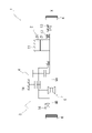
- FIG. 1 is a skeleton diagram explaining the unit.
- FIG. 2 is an external view of the unit.
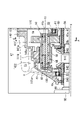
- FIG. 3 is a schematic cross-sectional view of the unit.
- FIG. 4 is an enlarged view around the differential case.
- FIG. 5 is an enlarged view around the planetary reduction gear.
- FIG. 6 is a diagram illustrating a cooling water circulation system in the unit.
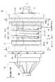
- FIG. 7 is a diagram for explaining cooling paths.
- FIG. 8 is a diagram for explaining cooling paths.
- FIG. 9 is a diagram explaining the rotation of the differential case.
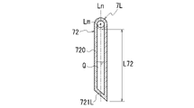
- FIG. 10 is a diagram explaining a heat pipe.
- FIG. 11 is a diagram explaining a heat pipe.
- FIG. 12 is a diagram explaining a heat pipe.
- FIG. 13 is a diagram explaining a heat pipe.
- FIG. 14 is a diagram illustrating the arrangement of heat pipes.
- FIG. 15 is a diagram illustrating the arrangement of heat pipes.
- FIG. 16 is a diagram illustrating the arrangement of heat pipes.
- a “unit” is also called a “motor unit”, a “power transmission device”, or the like.
- a motor unit is a unit having at least a motor.
- a power transmission device is a device having at least a power transmission mechanism, and the power transmission mechanism is, for example, a gear mechanism and/or a differential gear mechanism.
- a unit that is a device comprising a motor and a power transmission belongs to the concept of both a motor unit and a power transmission.
- the “housing” contains the motor, gear, and inverter.
- a housing consists of one or more cases.
- "3 in 1” means a form in which a part of the motor case that houses the motor and a part of the inverter case that houses the inverter are integrally formed.
- the cover and the case constitute one case
- the case accommodating the motor and the case accommodating the inverter are integrally formed.
- a "motor” is a rotating electric machine that has a motor function and/or a generator function.
- a second element (part, portion, etc.) connected to the first element (part, portion, etc.); a second element (part, portion, etc.) connected downstream of the first element (part, portion, etc.);
- a second element (part, section, etc.) connected upstream of an element (part, section, etc.)
- the first element and the second element are power-transmittably connected.
- the power input side is upstream, and the power output side is downstream.
- the first element and the second element may be connected via another element (clutch, other gear mechanism, etc.).
- “Overlapping when viewed from a predetermined direction” means that a plurality of elements are arranged in a predetermined direction, and has the same meaning as “overlapping in a predetermined direction”.
- the "predetermined direction” is, for example, an axial direction, a radial direction, a gravitational direction, a vehicle running direction (vehicle forward direction, vehicle backward direction), or the like. If a drawing shows that multiple elements (parts, parts, etc.) are lined up in a predetermined direction, there is a sentence in the description explaining that they overlap when viewed in a predetermined direction. can be regarded as
- not overlapped when viewed from a predetermined direction and “offset when viewed from a predetermined direction” mean that a plurality of elements are not aligned in a predetermined direction, and "not overlapped in a predetermined direction”. , is synonymous with the description of "offset in a predetermined direction".
- the "predetermined direction” is, for example, an axial direction, a radial direction, a gravitational direction, a vehicle running direction (vehicle forward direction, vehicle backward direction), or the like. If a drawing shows that multiple elements (parts, parts, etc.) are not aligned in a predetermined direction, the description of the specification includes a sentence explaining that they do not overlap when viewed in a predetermined direction. can be regarded as
- the first element is located between the second element (part, portion, etc.) and the third element (part, portion, etc.) when viewed from a predetermined direction" In the case it means that the first element can be observed to be between the second and third elements.
- the "predetermined direction” includes an axial direction, a radial direction, a gravity direction, a vehicle running direction (vehicle forward direction, vehicle backward direction), and the like. For example, when the second element, the first element, and the third element are arranged in this order along the axial direction, the first element is between the second element and the third element when viewed in the radial direction.
- the drawing shows that the first element is between the second element and the third element when viewed from a predetermined direction
- the first element is the second element when viewed from a predetermined direction in the description of the specification. It can be considered that there is a sentence explaining what is between the third element.
- Axial direction means the axial direction of the rotation axis of the parts that make up the unit.
- Rotary direction means a direction perpendicular to the rotation axis of the parts that make up the unit.
- the parts are, for example, motors, gear mechanisms, differential gear mechanisms, and the like.
- a rotating element of a planetary gear mechanism (for example, a sun gear, a carrier, a ring gear, etc.) is "fixed" to another element, which means that it may be directly fixed or fixed via another member. good.
- the downstream side in the rotational direction means the downstream side in the rotational direction when the vehicle moves forward or the rotational direction when the vehicle moves backward. It is preferable to set it to the downstream side in the rotational direction when the vehicle moves forward, which occurs frequently.
- the downstream side in the rotational direction of the planetary gear mechanism means the downstream side in the revolution direction of the pinion gear.
- a "catch tank” is an element (part, part, etc.) that has the function of a tank (container) into which oil is introduced.
- the term “catch” refers to the fact that oil is supplied to the tank from the outside of the tank.
- the catch tank is provided, for example, using at least part of the housing, or is provided separately from the housing. Integrally forming the catch tank and the housing contributes to a reduction in the number of parts.
- Coolant is a refrigerant, for example, liquid (cooling water, etc.), gas (air, etc.), etc. Coolant is a concept that includes oil, but when both oil and coolant are used in this specification, it means that coolant is composed of a material different from that of oil.
- a "heat exchange section” is an element (part, section, etc.) that exchanges heat between two different heat exchange media.
- Combinations of two heat exchange media are, for example, oil and cooling water, cooling water and air, air and oil, and the like.
- Heat pipe is a part separate from the housing. For example, heat exchange between cooling water and oil and/or air within the housing is performed via heat pipes.
- a "cabin” means a room in a vehicle where passengers board.
- FIG. 1 is a skeleton diagram for explaining the unit 1.
- FIG. FIG. 2 is an external view of the unit 1.
- FIG. FIG. 3 is a schematic cross-sectional view of the unit 1.
- FIG. FIG. 3 shows the state in which the inverter case is removed.
- FIG. 4 is an enlarged view around the differential case 50.
- FIG. 5 is an enlarged view around the planetary reduction gear 4.
- FIG. 6 is a diagram illustrating a circulation system 80 for cooling water W in the unit 1.
- FIG. 7 is a diagram illustrating the cooling path CP1.
- FIG. 7 shows a view from the same direction as FIG. In FIG.
- FIG. 7 shows the cover member 13 and the gear case 14 separated from the first case member 11 in the rotation axis X direction.
- FIG. 8 is a diagram illustrating the cooling path CP1.
- FIG. 8 shows the unit 1 of FIG. 2 viewed from below.
- the second case member 12 is indicated by phantom lines, and the areas of the protrusion 111c, the thick portions 118 and 119, and the heat pipe 7 are indicated by hatching.
- 8 shows the cover member 13 and the gear case 14 separated from the first case member 11 in the rotation axis X direction.
- 9A and 9B are diagrams for explaining the rotation of the differential case 50.
- FIG. FIG. 9 is a schematic diagram of the AA section of FIG.
- the unit 1 includes a motor 2, a power transmission mechanism 3 that transmits the power output by the motor 2 to drive wheels K, K of the vehicle, and an inverter IV (Fig. 2).
- the housing HS of the unit 1 is a "3 in 1" unit in which a portion of the motor case 10 that houses the motor 2 and an inverter case 17 that houses the inverter IV are integrally formed.
- the unit 1 includes a power transmission mechanism 3, a planetary reduction gear 4 (reduction gear mechanism, planetary gear mechanism), a differential mechanism 5 (differential gear mechanism), and an output shaft. It has a certain drive shaft 9 (9A, 9B).
- a planetary reduction gear 4 a differential mechanism 5, and a drive shaft 9 (9A, 9B) are provided along a transmission path for output rotation of the motor 2 around the rotation axis X.
- the axis of the drive shaft 9 ( 9 A, 9 B) is coaxial with the rotation axis X of the motor 2
- the differential mechanism 5 is coaxial with the motor 2 .
- the planetary reduction gear 4 is connected downstream of the motor 2 .
- a differential mechanism 5 is connected downstream of the motor 2 via a planetary reduction gear 4 .
- a drive shaft 9 ( 9 A, 9 B) is connected downstream of the differential mechanism 5 .
- the housing HS of the unit 1 is a 3-in-1 type housing and accommodates the motor 2, the power transmission mechanism 3, and the inverter IV.
- the housing HS is composed of one or more cases.
- the housing HS has, for example, a motor case 10 that houses the motor 2, a gear case 14 that houses the power transmission mechanism 3, and an inverter case 17 that houses the inverter IV.
- a gear case 14 is joined to one end side of the motor case 10 in the rotation axis X direction.
- the inverter case 17 is joined above the motor case 10 in the direction of gravity when the unit 1 is mounted on the vehicle.
- the inverter IV is an electronic component that includes a smoothing capacitor, power semiconductor element, driver board, etc.
- the inverter IV is electrically connected to the motor 2 inside the motor case 10 by wiring (not shown).
- the motor 2 has a portion that overlaps the differential mechanism 5 (differential gear mechanism) when viewed in the axial direction (see FIG. 3).
- differential mechanism 5 differential gear mechanism
- “when viewed in the axial direction” means when viewed from the rotation axis X direction.
- the motor 2 has a portion that overlaps the planetary reduction gear 4 (reduction gear mechanism).
- the planetary reduction gear 4 (reduction gear mechanism) has a portion that overlaps the differential mechanism 5 (differential gear mechanism).
- the planetary reduction gear 4 (reduction gear mechanism) has a portion that overlaps the motor 2 .
- the differential mechanism 5 (differential gear mechanism) has a portion that overlaps the planetary reduction gear 4 (reduction gear mechanism).
- the differential mechanism 5 (differential gear mechanism) has a portion that overlaps the motor 2 when viewed in the axial direction.
- the motor 2 When viewed in the axial direction, the motor 2 has a portion that overlaps the differential mechanism 5 (differential gear mechanism).
- the motor case 10 includes a first case member 11, a second case member 12 fitted around the first case member 11, and a cover member 13 joined to one end of the first case member 11.
- the first case member 11 has a cylindrical support wall portion 111 and a flange-like joint portion 112 provided at one end 111 a of the support wall portion 111 .
- the support wall portion 111 is provided along the rotation axis X of the motor 2 .
- the motor 2 is accommodated inside the support wall portion 111 .
- the second case member 12 includes a cylindrical peripheral wall portion 121, a flange-shaped joint portion 122 provided at one end 121a of the peripheral wall portion 121, and a flange-shaped joint portion 123 provided at the other end 121b of the peripheral wall portion 121. and have The peripheral wall portion 121 of the second case member 12 is formed with an inner diameter that allows it to be externally inserted into the support wall portion 111 of the first case member 11 .
- the first case member 11 and the second case member 12 are assembled together by externally inserting the peripheral wall portion 121 of the second case member 12 into the supporting wall portion 111 of the first case member 11 .
- the joint portion 122 on the one end 121a side of the peripheral wall portion 121 abuts the joint portion 112 of the first case member 11 from the rotation axis X direction.
- These joints 122 and 112 are connected to each other by bolts (not shown).
- thick portions 118 and 119 are provided on the one end 111a side and the other end 111b side of the support wall portion 111 .
- the thick portions 118 and 119 protrude radially outward from the outer periphery of the support wall portion 111 .
- the radial thickness H2 of the thick portions 118 and 119 is greater than the radial thickness H1 of the support wall portion 111 (see FIG. 3).
- the thick portions 118 and 119 are provided over the entire circumference of the support wall portion 111 in the circumferential direction around the rotation axis X.
- Seal grooves 113 and 113 are opened in the outer peripheral surfaces of the thick portions 118 and 119, respectively.
- the seal grooves 113, 113 are provided along the circumferential direction around the rotation axis X, and are provided over the entire circumferential direction around the rotation axis X of the thick portions 118, 119, respectively.
- through holes 118a and 119a are formed in the thick portions 118 and 119 so as to pass through the thick portions 118 and 119 in the rotation axis X direction.
- the insertion hole 118a opens to one end 111a of the support wall portion 111 in the rotation axis X direction and the cooling path CP1.
- the insertion hole 119a opens to the other end 111b of the support wall portion 111 in the rotation axis X direction and the cooling path CP1.
- Heat pipes 7, 7, which will be described later, are inserted through the insertion holes 118a, 119a, respectively.
- the heat pipes 7,7 have a diameter R1 smaller than the radial thickness H2 of the thick portions 118,119.
- the seal grooves 113, 113 are fitted with seal materials C, C. These sealing materials C, C are pressed against the inner periphery of the peripheral wall portion 121 that is fitted over the support wall portion 111 to seal the gap between the outer periphery of the support wall portion 111 and the inner periphery of the peripheral wall portion 121. do.
- a projection 111c is provided on the outer circumference of the support wall portion 111 of the first case member 11. As shown in FIG. The protrusion 111c is provided in a region between the thick portions 118 and 119 in the rotation axis X direction.
- the radial thickness (protrusion height) of the projection 111 c in the radial direction of the rotation axis X is the same as the radial thickness H2 of the thick portions 118 and 119 .
- the projection 111c is one wall that extends in the circumferential direction around the rotation axis X and surrounds the rotation axis X at intervals.
- the projection 111c is provided along the entire circumference of the support wall portion 111 along the circumferential direction around the rotation axis X.
- the protrusions 111c are provided with phase shifts in the circumferential direction around the rotation axis X, and are provided in a spiral shape in which the positions in the rotation axis X direction are different from the one end 111a side of the support wall portion 111 toward the other end 111b side. ing.
- the projection 111c When viewed in the radial direction, the projection 111c is provided along a straight line Lq inclined from a straight line Lp perpendicular to the rotation axis X. As shown in FIG. The angle ⁇ between the straight lines Lp and Lq is the lead angle forming the spiral.
- the protrusion 111c is connected to the thick portion 118 via the connection wall 111d.
- the projection 111c is connected to the thick portion 119 via the connection wall 111e.
- the connection walls 111d and 111e are provided along the rotation axis X, respectively.
- the projection height (thickness) of the connection walls 111d and 111e in the radial direction of the rotation axis X is the same as the thickness H2 (see FIG. 7) of the projection 111c and the thick portions 118 and 119. As shown in FIG.
- the peripheral wall portion 121 of the second case member 12 is fitted onto the support wall portion 111 of the first case member 11 (see the phantom lines in FIGS. 7 and 8).
- the peripheral wall portion 121 of the second case member 12 contacts the thick portions 118 and 119 of the support wall portion 111 of the first case member 11, the projection 111c, and the connection walls 111d and 111e.
- a spiral space is formed that continues from the one end 111a side of the support wall portion 111 toward the other end 111b side.
- This spiral space forms a cooling passage CP1 through which cooling water W (see FIG. 6), which is a coolant, flows.
- the cooling water W exchanges heat with the motor 2 housed inside the support wall portion 111 via the support wall portion 111 .
- the spiral cooling path CP1 is simplified and shown in a straight line.
- the cooling path CP1 has an inlet CP1a for the cooling water W at a portion surrounded by the projection 111c, the thick portion 118, and the connection wall 111d on the one end 111a side of the support wall portion 111.
- the cooling path CP1 has an outlet CP1b for the cooling water W at a portion surrounded by the protrusion 111c, the thick portion 119, and the connection wall 111e on the side of the other end 111b of the support wall portion 111.
- An inlet CP1a and an outlet CP1b of the cooling water W correspond to the start point and end point of the spiral space, respectively.
- one end of a pipe P1 is connected to an inlet CP1a of the cooling path CP1.
- the other end of the pipe P1 is connected to a cooling path CP2 of the inverter case 17, which will be described later.
- One end of the pipe P2 is connected to the outlet CP1b of the cooling path CP1.
- the other end of the pipe P2 is connected to an oil cooler 83, which will be described later.
- the pipes P1 and P2 are provided so as to pass through the peripheral wall portion 121 of the second case member 12, respectively.
- the other end 121b of the second case member 12 is provided with a wall portion 120 (cover) extending radially inward.
- the wall portion 120 is provided in a direction perpendicular to the rotation axis X.
- An opening 120a through which the drive shaft 9A is inserted is formed in a region of the wall portion 120 intersecting with the rotation axis X.
- a motor support portion 125 extending toward the motor 2 is provided on the surface of the wall portion 120 on the side of the motor 2 (right side in the figure).
- the motor support portion 125 has a tubular shape surrounding the opening 120a with a gap therebetween.
- the motor support portion 125 is inserted inside a coil end 253b, which will be described later.
- the motor support portion 125 faces the end portion 21b of the rotor core 21 with a gap in the rotation axis X direction.
- a bearing B ⁇ b>1 is supported on the inner circumference of the motor support portion 125 .
- the outer circumference of the motor shaft 20 is supported by a motor support portion 125 via a bearing B1.
- a cylindrical wall portion 126 extending toward the differential mechanism 5 is provided on the surface of the wall portion 120 on the side of the differential mechanism 5 (on the left side in the drawing).
- the cylindrical wall portion 126 has a cylindrical shape surrounding the opening 120a, and the inner circumference of the cylindrical wall portion 126 supports a bearing B2.
- a cylindrical wall portion 61 of the differential case 50, which will be described later, is supported by a cylindrical wall portion 126 via the bearing B2.
- the cover member 13 has a wall portion 133 orthogonal to the rotation axis X, a joint portion 132 and a lid portion 130 .
- the cover member 13 When viewed from the first case member 11, the cover member 13 is located on the side opposite to the differential mechanism 5 (on the right side in the drawing).
- the joint portion 132 of the cover member 13 surrounds the outer peripheral edge of the wall portion 133 .
- the joint portion 132 extends from the wall portion 133 toward the first case member 11 in the rotation axis X direction.
- the joint portion 132 is joined to the joint portion 112 of the first case member 11 from the rotation axis X direction.
- the cover member 13 and the first case member 11 are connected to each other with bolts (not shown). In this state, the cover member 13 closes the opening of the support wall portion 111 on the joint portion 112 side (right side in the figure) of the first case member 11 .
- the lid portion 130 of the cover member 13 is located on the side opposite to the joint portion 132 when viewed from the wall portion 133 (on the right side in the drawing).
- the lid portion 130 is joined to the wall portion 133 from the rotation axis X direction.
- the lid portion 130 is connected to the wall portion 133 with bolts (not shown).
- An insertion hole 130a for the drive shaft 9A is provided in the central portion of the lid portion 130.
- a lip seal RS is provided on the inner circumference of the insertion hole 130a.
- the lip seal RS brings the lip portion (not shown) into elastic contact with the outer circumference of the drive shaft 9A.
- a gap between the inner periphery of the insertion hole 130a and the outer periphery of the drive shaft 9A is sealed with a lip seal RS.
- a peripheral wall portion 131 surrounding the insertion hole 130a is provided on the surface of the lid portion 130 on the side of the first case member 11 (left side in the drawing).
- a drive shaft 9A is supported on the inner periphery of the peripheral wall portion 131 via a bearing B4.
- a motor support portion 135 and a connection wall 136 are provided on the inner diameter side of the joint portion 132 .
- the motor support portion 135 is provided on the motor 2 side (left side in the figure) when viewed from the peripheral wall portion 131 .
- the motor support portion 135 has a tubular shape surrounding the rotation axis X with a space therebetween.
- a cylindrical connection wall 136 is connected to the outer periphery of the motor support portion 135 .
- the connection wall 136 is formed with a larger outer diameter than the peripheral wall portion 131 on the lid portion 130 side (right side in the drawing).
- the connection wall 136 is oriented along the rotation axis X and extends away from the motor 2 .
- the connection wall 136 connects the motor support portion 135 and the joint portion 132 .
- One end 20a side of the motor shaft 20 penetrates the inside of the motor support portion 135 from the motor 2 side to the peripheral wall portion 131 side.
- a bearing B ⁇ b>1 is supported on the inner periphery of the motor support portion 135 .
- the outer circumference of the motor shaft 20 is supported by a motor support portion 135 via a bearing B1.
- a lip seal RS is provided at a position adjacent to the bearing B1.
- Oil holes 136 a and 136 b are opened on the inner periphery of the connection wall 136 .
- the oil OL flows into the space (internal space Sc) surrounded by the connection wall 136 and the lid portion 130 through the oil hole 136a.
- the oil OL that has flowed into the internal space Sc is discharged from the oil hole 136b.
- the lip seal RS is provided to prevent the oil OL in the connection wall 136 from flowing into the motor 2 side.
- the gear case 14 has a peripheral wall portion 141 and a flange-like joint portion 142 provided at the end portion of the peripheral wall portion 141 on the motor case 10 side.
- a support portion 145 for a bearing B2, which will be described later, is provided at an end portion of the peripheral wall portion 141 opposite to the joint portion 142 (on the left side in the figure).
- the planetary reduction gear 4 and the differential mechanism 5 which are the power transmission mechanism 3 are accommodated inside the peripheral wall portion 141 .
- the peripheral wall portion 141 includes a cylindrical wall portion 141a connected to the joint portion 142, an inclined portion 141c (inclined surface) connected to the support portion 145, and the cylindrical wall portion 141a and the inclined portion 141c. It has a connection wall portion 141b for connection.
- the tubular wall portion 141a and the connecting wall portion 141b are gradually reduced in diameter from the joint portion 142 and connected to the inclined portion 141c.
- the inclined portion 141c is inclined such that the inner diameter decreases from the connection wall portion 141b toward the support portion 145 .
- the gear case 14 is located on the differential mechanism 5 side (left side in the figure) when viewed from the motor case 10 .
- the joint portion 142 of the gear case 14 is joined to the joint portion 123 of the second case member 12 of the motor case 10 from the rotation axis X direction.
- the gear case 14 and the second case member 12 are connected to each other by bolts (not shown).
- the space formed inside the joined motor case 10 and gear case 14 is partitioned into two by the wall portion 120 (cover) of the second case member 12 .
- the motor case 10 side of the wall portion 120 is a motor chamber Sa that houses the motor 2
- the gear case 14 side of the wall portion 120 is a gear chamber Sb that houses the power transmission mechanism 3 .
- a wall portion 120 as a cover is sandwiched between the motor 2 and the differential mechanism 5 inside the housing HS.
- the cover here may have a portion housed within the housing HS, and like the wall portion 120, the entire cover may be housed in the housing HS. Also, the cover may be separate from the second case member 12, for example. In this case, the cover may be sandwiched between the motor case 10 and the gear case 14 and fixed. A part of the cover may be exposed outside the housing HS.
- the motor 2 has a cylindrical motor shaft 20, a cylindrical rotor core 21 fitted onto the motor shaft 20, and a stator core 25 surrounding the outer circumference of the rotor core 21 with a gap.
- bearings B ⁇ b>1 and B ⁇ b>1 are externally inserted and fixed on both sides of the rotor core 21 .
- a bearing B ⁇ b>1 positioned on the one end 20 a side (right side in the drawing) of the motor shaft 20 when viewed from the rotor core 21 is supported on the inner periphery of the motor support portion 135 of the cover member 13 .
- a bearing B ⁇ b>1 positioned on the other end 20 b side (left side in the drawing) is supported on the inner periphery of the motor support portion 125 of the second case member 12 .
- the motor support portions 135, 125 are arranged on the inner diameter side of coil ends 253a, 253b, which will be described later.
- the motor support portions 135 and 125 are arranged to face one end portion 21a and the other end portion 21b of the rotor core 21 with a gap in the rotation axis X direction.
- the rotor core 21 is formed by laminating a plurality of silicon steel plates. Each of the silicon steel plates is fitted over the motor shaft 20 in a state where relative rotation with the motor shaft 20 is restricted.
- the silicon steel plate has a ring shape when viewed from the rotation axis X direction of the motor shaft 20 .
- N-pole and S-pole magnets are provided alternately in the circumferential direction around the rotation axis X on the outer peripheral side of the silicon steel plate.
- a stator core 25 surrounding the outer periphery of the rotor core 21 is formed by laminating a plurality of electromagnetic steel sheets.
- the stator core 25 is fixed to the inner periphery of the cylindrical support wall portion 111 of the first case member 11 .
- Each of the electromagnetic steel sheets has a ring-shaped yoke portion 251 fixed to the inner periphery of the support wall portion 111 and tooth portions 252 protruding from the inner periphery of the yoke portion 251 toward the rotor core 21 side.
- the stator core 25 having a configuration in which the windings 253 are distributed over a plurality of teeth 252 is employed.
- the stator core 25 is longer than the rotor core 21 in the direction of the rotation axis X by the coil ends 253a and 253b projecting in the direction of the rotation axis X.
- the coil ends 253a and 253b are opposed to the heat pipes 7 and 7, respectively, which will be described later, with a gap therebetween in the rotation axis X direction.
- a stator core in which windings are concentratedly wound may be employed for each of the plurality of tooth portions 252 protruding toward the rotor core 21 side.
- the wall portion 120 (motor support portion 125) of the second case member 12 is provided with an opening 120a.
- the other end 20b side of the motor shaft 20 passes through the opening 120a to the differential mechanism 5 side (left side in the figure) and is positioned inside the gear case 14 .
- the other end 20b of the motor shaft 20 faces a side gear 54A, which will be described later, with a gap in the rotation axis X direction.
- a lip seal RS is inserted between the motor shaft 20 and the opening 120 a of the wall portion 120 .
- Oil OL for lubricating the planetary reduction gear 4 and the differential mechanism 5 is enclosed in the inner diameter side of the gear case 14 .
- Lip seal RS is provided to prevent oil OL in gear case 14 from flowing into motor case 10 .
- the sun gear 41 of the planetary reduction gear 4 is spline-fitted to the region of the motor shaft 20 located within the gear case 14 .
- a toothed portion 41a is formed on the outer periphery of the sun gear 41, and a large-diameter gear portion 431 of the stepped pinion gear 43 is meshed with the toothed portion.
- the stepped pinion gear 43 has a large-diameter gear portion 431 (large pinion) that meshes with the sun gear 41 and a small-diameter gear portion 432 (small pinion) having a smaller diameter than the large-diameter gear portion 431 .
- the large-diameter gear portion 431 and the small-diameter gear portion 432 are integral gear components arranged side by side in the direction of the axis X1 parallel to the rotation axis X. As shown in FIG.
- the pinion shaft 44 penetrates the inner diameter side of the large-diameter gear portion 431 and the small-diameter gear portion 432 .
- the stepped pinion gear 43 is rotatably supported on the outer circumference of the pinion shaft 44 via needle bearings NB, NB.
- the differential mechanism 5 has a differential case 50 (differential case) as an input element, a drive shaft (output shaft) as an output element, and a differential gear set as a differential element.
- the differential case 50 may be composed of two case members assembled in the rotation axis X direction.
- the differential case 50 also functions as a carrier that supports the stepped pinion gear 43 of the planetary reduction gear 4.
- the stepped pinion gear 43 is rotatably supported by the differential case 50 via the pinion shaft 44 .
- the three stepped pinion gears 43 are circumferentially spaced around the rotation axis X. As shown in FIG.
- a pinion mate gear 52 which is a bevel gear type differential gear, and side gears 54A and 54B are provided as a differential gear set.
- the pinion mate gear 52 is supported by the pinion mate shaft 51 .
- the pinion mate shaft 51 has a central member 510 arranged on the rotation axis X and a shaft member 511 connected to the outer diameter side of the central member 510 .
- a plurality of shaft members 511 are provided in the circumferential direction around the rotation axis X at equal intervals.
- the shaft member 511 is inserted through a radially extending support hole 69 of the differential case 50 and supported.
- the pinion mate gears 52 are fitted one by one onto each of the shaft members 511 and are rotatably supported.
- the side gear 54A is positioned on one side of the central member 510 in the rotation axis X direction, and the side gear 54B is positioned on the other side.
- the side gears 54A, 54B are rotatably supported by the differential case 50, respectively.
- the side gear 54A meshes with the pinion mate gear 52 from one side in the rotation axis X direction.
- the side gear 54B meshes with the pinion mate gear 52 from the other side in the rotation axis X direction.
- An opening 60 and a cylindrical wall portion 61 surrounding the opening 60 are provided in the central portion of one end side (right side in the drawing) of the differential case 50 .
- the tubular wall portion 61 extends in a direction away from the side gear 54A.
- the outer circumference of the cylinder wall portion 61 is supported by the wall portion 120 of the second case member 12 via the bearing B2.
- the drive shaft 9A is inserted through the opening 60 from the rotation axis X direction.
- the drive shaft 9A passes through the insertion hole 130a of the lid portion 130 of the cover member 13, and extends through the inner diameter side of the motor shaft 20 of the motor 2 and the sun gear 41 (see FIG. 4) of the planetary reduction gear 4. are provided across the rotation axis X direction.
- a through hole 65 and a tubular wall portion 66 surrounding the through hole 65 are formed in the center of the other end side (left side in the drawing) of the differential case 50 .
- a bearing B ⁇ b>2 is fitted on the cylindrical wall portion 66 .
- the bearing B ⁇ b>2 externally inserted into the cylinder wall portion 66 is held by the support portion 145 of the gear case 14 .
- a tubular wall portion 66 of the differential case 50 is rotatably supported by the gear case 14 via a bearing B2.
- the drive shaft 9B passing through the opening 145a of the gear case 14 is inserted into the support portion 145 from the rotation axis X direction.
- the drive shaft 9B is rotatably supported by a support portion 145.
- the cylinder wall portion 66 functions as a shaft support portion that supports the outer circumference of the drive shaft 9B.
- a lip seal RS is fixed to the inner circumference of the opening 145a.
- a lip portion (not shown) of the lip seal RS is in elastic contact with the outer circumference of the cylinder wall portion 540 of the side gear 54B externally fitted on the drive shaft 9B. As a result, the gap between the outer circumference of the cylindrical wall portion 540 of the side gear 54B and the inner circumference of the opening 145a is sealed.
- the tip portions of the drive shafts 9 (9A, 9B) face each other with a gap in the rotation axis X direction.
- Side gears 54A and 54B supported by a differential case 50 are spline-fitted to the outer circumferences of the tip portions of the drive shafts 9 (9A and 9B), respectively.
- the side gears 54A, 54B and the drive shafts 9 (9A, 9B) are connected to each other so as to rotate about the rotation axis X together.
- the side gears 54A and 54B are arranged opposite to each other with a gap in the rotation axis X direction.
- a central member 510 of the pinion mate shaft 51 is positioned between the side gears 54A, 54B.
- the pinion mate gear 52 of the pinion mate shaft 51 is assembled to a side gear 54A positioned on one side in the direction of the rotation axis X and a side gear 54B positioned on the other side in a state in which the teeth thereof are meshed with each other.
- a support hole 62 on the one end 44a side of the pinion shaft 44 is formed on the outer diameter side of the opening 60 on the one end side (right side in the drawing) of the differential case 50 .
- a support hole 68 on the side of the other end 44b of the pinion shaft 44 is formed in the other end side of the differential case 50 (left side in the drawing).
- the support holes 62 and 68 are formed at overlapping positions in the rotation axis X direction.
- the support holes 62 and 68 are formed at intervals in the circumferential direction around the rotation axis X so as to match the position where the stepped pinion gear 43 is arranged.
- One end 44 a of the pinion shaft 44 is inserted into the support hole 62 and the other end 44 b is inserted into the support hole 68 .
- the other end 44 b of the pinion shaft 44 is press-fitted into the support hole 68 so that the pinion shaft 44 is fixed to the differential case 50 so as not to rotate relative to it.
- a stepped pinion gear 43 externally fitted on the pinion shaft 44 is rotatably supported around an axis X1 parallel to the rotation axis X. As shown in FIG.
- lubricating oil OL is stored inside the gear case 14 .
- the differential case 50 rotates around the rotation axis X, the oil OL is scraped up by the differential case 50 .
- the differential case 50, the pinion shaft 44, and the like are provided with oil passages, oil holes, and the like for introducing oil that has been raked up by the differential case 50. As shown in FIG. This makes it easier for the oil OL to be introduced into rotating members such as the bearing B2 and the needle bearing NB (see FIG. 5).
- a catch tank 15 is provided above the space in which the differential case 50 is accommodated inside the gear case 14 .
- the catch tank 15 is positioned on one side (right side in the drawing) of a vertical line VL perpendicular to the rotation axis X. As shown in FIG.
- the catch tank 15 communicates with the gear chamber Sb through the communication port 150 .
- the oil OL that has been scraped up and scattered by the differential case 50 flows into the catch tank 15 and is collected.
- the catch tank 15 is positioned on the right side of the vertical line VL, that is, on the downstream side in the rotational direction of the differential case 50 .
- the catch tank 15 is connected to an oil cooler 83 (see FIG. 6) via an oil passage, piping, etc. (not shown).
- the oil cooler 83 is connected to an oil hole 136a (see FIG. 3) formed in the connection wall 136 via a pipe, an oil passage and the like (not shown).
- the peripheral wall portion 141 of the gear case 14 is formed with an oil hole Ha.
- the oil hole Ha is connected via a pipe (not shown) to an oil hole 136b formed in the internal space Sc.
- the oil OL discharged from the internal space Sc through the oil hole 136b is re-supplied into the gear chamber Sb through the oil hole Ha.
- the unit 1 is provided with a cooling water W circulation system 80 .
- the circulation system 80 circulates the cooling water W between the cooling path CP ⁇ b>1 of the motor case 10 and the cooling path CP ⁇ b>2 of the inverter case 17 .
- the circulation system 80 further includes an oil cooler 83, a water pump WP, and a radiator 82 between the cooling paths CP1 and CP2, which are connected by pipes or the like through which cooling water W flows.
- the water pump WP pumps cooling water W through the circulation system 80 .
- the radiator 82 is a device that dissipates the heat of the cooling water W and cools it.
- the oil cooler 83 is a heat exchanger that exchanges heat between the cooling water W and the oil OL.
- the cooling water W pressure-fed to the water pump WP is supplied to the oil cooler 83 through the cooling path CP1 in the motor case 10 after flowing through the cooling path CP2 in the inverter case 17 .
- the oil cooler 83 cools the oil OL by exchanging heat between the cooling water W and the oil OL.
- the cooling water W flowing through the oil cooler 83 is cooled by the radiator 82 and then supplied to the cooling path CP2 of the inverter case 17 again.
- heat pipe 7 heat pipe 7 for cooling the motor 2 .
- the heat pipes 7 are provided around the coil ends 253a and 253b of the motor 2 in the rotation axis X direction.
- the heat pipe 7 is a single pipe material made of a metal material with high thermal conductivity (for example, copper or aluminum).
- the heat pipes 7 provided around the coil ends 253a and 253b are arranged on the left side of a vertical line VL passing through the rotation axis X direction when the coil ends 253a and 253b are viewed from the rotation axis X direction. 7L and a heat pipe 7R arranged on the right side of the vertical line VL (see FIGS. 14 and 15).
- the heat pipe 7 is also simply referred to, unless otherwise specified.
- FIG. 10 is a diagram illustrating the heat pipe 7L.
- FIG. 10 is a schematic cross-sectional view of the heat pipe 7L.
- FIG. 11 is a diagram illustrating the heat pipe 7L.
- FIG. 11 is a schematic diagram of the AA section of FIG.
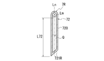
- FIG. 12 is a diagram illustrating the heat pipe 7R.
- FIG. 12 is a schematic cross-sectional view of the heat pipe 7R.
- FIG. 13 is a diagram illustrating the heat pipe 7R.
- FIG. 13 is a schematic diagram of the AA cross section of FIG.
- FIG. 14 is a diagram for explaining the arrangement of the heat pipes 7. As shown in FIG. 14 is a view taken along the line AA in FIG. 7.
- FIG. FIG. 15 is a diagram for explaining the arrangement of the heat pipes 7. As shown in FIG.
- FIG. 15 is a view taken along line BB in FIG. 7.
- FIG. 14 and 15 for convenience of explanation, the support wall portion 111 and the peripheral wall portion 121 are shown in cross section, and the thick portions 118 and 119 are omitted. Also, the regions where the coil ends 253a and 253b are provided are indicated by cross hatching.
- FIG. 16 is a diagram illustrating the arrangement of the heat pipes 7. As shown in FIG. FIG. 16 is an enlarged view around the heat pipe 7 in FIG.
- FIG. 17 is a diagram illustrating heat exchange by the heat pipe 7.
- the heat pipe 7L is formed by bending one pipe material at one point between one end 7a and the other end 7b in the longitudinal direction.
- the heat pipe 7L has a substantially L shape when viewed from the side.
- the heat pipe 7L includes a first tubular portion 71 provided in a direction along a straight line Lm parallel to the longitudinal direction and a second tubular portion 71 provided in a direction along a straight line Ln that intersects the straight line Lm.
- a portion 72 and a connection portion 75 that connects the first tubular portion 71 and the second tubular portion 72 .
- the heat pipe 7L has a first tubular portion 71 on the one end 7a side and a second tubular portion 72 on the other end 7b side with the connecting portion 75 as a boundary.
- the length L71 of the first tubular portion 71 in the direction of the straight line Lm is longer than the lengths L1 and L2 (see FIG. 16) of the thick portions 118 and 119 in the direction of the rotation axis X (L71>L1 , L2).
- a length L72 of the second tubular portion 72 in the direction of the straight line Ln is longer than the thickness T (see FIG. 16) of the coil ends 253a and 253b in the radial direction of the rotation axis X (L72>T).
- the straight line Lm along the longitudinal direction of the first tubular portion 71 is inclined by an angle ⁇ from the straight line Lm'.
- the straight line Lm′ is orthogonal to the straight line Ln along the longitudinal direction of the second tubular portion 72 .
- the first tubular portion 71 is inclined in a direction away from the other end 7b along the straight line Lm from the connecting portion 75 toward the one end 7a.
- the first tubular portion 71 has a bottom wall portion 711 that intersects the straight line Lm, and a tubular wall portion 710 that surrounds the entire outer circumference of the bottom wall portion 711 .
- the bottom wall portion 711 is inclined in a direction approaching the straight line Ln from one side (the upper side in the drawing) to the other side (the lower side in the drawing) across the straight line Lm.
- the cylindrical wall portion 710 extends from the bottom wall portion 711 to the other side (left side in the drawing) in the direction of the straight line Lm.
- the cylindrical wall portion 710 is connected to the connecting portion 75 on the other side in the direction of the straight line Lm.
- connection portion 75 is connected to the second tubular portion 72 on the side opposite to the first tubular portion 71 in the direction of the straight line Lm.
- the second cylindrical portion 72 has a cylindrical wall portion 720 surrounding the straight line Ln and a bottom wall portion 721L closing the opening of the cylindrical wall portion 720 .
- the cylindrical wall portion 720 extends in the direction of the straight line Ln in a direction away from the connection portion 75 (downward in the drawing).
- the bottom wall portion 721L is provided on the side opposite to the connection portion 75 in the direction of the straight line Ln.
- the bottom wall portion 721L is inclined toward the straight line Lm from one side (the right side in the drawing) to the other side (the left side in the drawing) across the straight line Ln. Therefore, when viewed from the direction of the straight line Lm, the length L72 of the second tubular portion 72 is shorter on the other side (left side in the drawing) than on one side (right side in the drawing) across the straight line Ln.
- the heat pipe 7R is also formed by bending one pipe material at one point between one end 7a and the other end 7b in the longitudinal direction.
- the heat pipe 7R has a substantially L shape when viewed from the side.
- the heat pipe 7R includes a first tubular portion 71 provided in a direction along a straight line Lm parallel to the longitudinal direction and a second tubular portion 71 provided in a direction along a straight line Ln that intersects the straight line Lm.
- a portion 72 and a connection portion 75 that connects the first tubular portion 71 and the second tubular portion 72 .
- the heat pipe 7R has a first tubular portion 71 on the one end 7a side and a second tubular portion 72 on the other end 7b side with the connecting portion 75 as a boundary.
- the length L71 of the first tubular portion 71 in the direction of the straight line Lm is longer than the lengths L1 and L2 (see FIG. 16) of the thick portions 118 and 119 in the direction of the rotation axis X (L71>L1 , L2).
- a length L72 of the second tubular portion 72 in the direction of the straight line Ln is longer than the thickness T (see FIG. 16) of the coil ends 253a and 253b in the radial direction of the rotation axis X (L72>T).
- the straight line Lm along the longitudinal direction of the first cylindrical portion 71 is inclined by an angle ⁇ from the straight line Lm'.
- the straight line Lm′ is orthogonal to the straight line Ln along the longitudinal direction of the second tubular portion 72 .
- the first tubular portion 71 is inclined in a direction away from the other end 7b along the straight line Lm from the connecting portion 75 toward the one end 7a.
- the first tubular portion 71 has a bottom wall portion 711 that intersects the straight line Lm, and a tubular wall portion 710 that surrounds the entire outer circumference of the bottom wall portion 711 .
- the bottom wall portion 711 is inclined toward the straight line Ln from one side (upper side in the drawing) to the other side (lower side in the drawing) across the straight line Lm.
- the cylindrical wall portion 710 extends from the bottom wall portion 711 to the other side (left side in the drawing) in the direction of the straight line Lm.
- the cylindrical wall portion 710 is connected to the connecting portion 75 on the other side in the direction of the straight line Lm.
- connection portion 75 is connected to the second tubular portion 72 on the side opposite to the first tubular portion 71 in the direction of the straight line Lm.
- the second cylindrical portion 72 has a cylindrical wall portion 720 surrounding the straight line Ln and a bottom wall portion 721R closing the opening of the cylindrical wall portion 720 .
- the cylindrical wall portion 720 extends in the direction of the straight line Ln in a direction away from the connecting portion 75 (downward in the figure).
- the bottom wall portion 721R is provided on the side opposite to the connecting portion 75 in the direction of the straight line Ln.
- the bottom wall portion 721R is inclined toward the straight line Lm as it goes from the other side (the left side in the drawing) to the one side (the right side in the drawing) across the straight line Ln. Therefore, when viewed from the direction of the straight line Lm, the length L72 of the second tubular portion 72 is shorter on one side (right side in the drawing) than on the other side (left side in the drawing) across the straight line Ln.
- the internal spaces of the first cylindrical portion 71, the connecting portion 75 and the second cylindrical portion 72 communicate with each other.
- One continuous internal space S is formed within 7 (7L, 7R).
- a refrigerant Q is sealed in the internal space S.
- Refrigerant Q is a liquid that boils at 50-60 degrees.
- the refrigerant Q sealed in the internal space S repeats evaporation and condensation, thereby exchanging heat with the space around the heat pipes 7 (7L, 7R). .
- the heat pipe 7 is attached to the first case member 11. As shown in FIG. Specifically, the cylindrical wall portion 710 of the heat pipe 7 is inserted into the insertion hole 118a provided in the thick portion 118 of the first case member 11 from one end 111a side (right side in the drawing) in the direction of the rotation axis X. Further, the cylindrical wall portion 710 of the heat pipe 7 is inserted into the insertion hole 119a provided in the thick portion 119 of the first case member 11 from the other end 111b side (left side in the figure) in the rotation axis X direction.
- the insertion hole 118a extends in the direction of the rotation axis X and is slightly inclined such that the opening on the side of the cooling path CP1 is located above the opening on the side of the one end 111a in the direction of the vertical line VL.
- the inclination angle of the insertion hole 118a is the same as the inclination angle ⁇ of the first tubular portion 71 (see FIGS. 10 and 12).
- the insertion hole 119a extends in the direction of the rotation axis X and is slightly inclined such that the opening on the side of the cooling path CP1 is located above the opening on the side of the other end 111b in the direction of the vertical line VL.
- the inclination angle of the insertion hole 118b is the same as the inclination angle ⁇ of the first tubular portion 71 (see FIGS. 10 and 12).
- the heat pipe 7 When the cylindrical wall portions 710, 710 of the heat pipes 7, 7 are inserted into the insertion holes 118a, 119a, respectively, one end 7a side of the heat pipe 7 is exposed inside the cooling path CP1. The other end 7b side of the heat pipe 7 is exposed inside the motor chamber Sa. In the direction of the vertical line VL, the heat pipe 7 has one end 7a located above the other end 7b.
- a ring groove 713 is opened on the outer peripheral surface of the cylindrical wall portion 710 of the first cylindrical portion 71 .
- a seal ring C is fitted in the ring groove 713 .
- the seal ring C presses against the through hole 118 a of the thick portion 118 to seal the gap between the cylindrical wall portion 710 and the support wall portion 111 .
- the seal ring C is pressed against the through hole 119 a of the thick portion 119 to seal the gap between the cylindrical wall portion 710 and the support wall portion 111 . This prevents the cooling water W in the cooling path CP1 from leaking into the motor chamber Sa.
- the cylindrical wall portions 720, 720 face the coil ends 253a, 253b in the rotation axis X direction with a gap therebetween. That is, the other end 7b side of the heat pipe 7 is a facing portion facing the coil ends 253a and 253b. Further, the tip surface 253b1 of the coil end 253b faces the cylinder wall portion 720 of the heat pipe 7 in the rotation axis X direction with a gap CL1 therebetween. A tip surface 253a1 of the coil end 253a faces the cylinder wall portion 720 of the heat pipe 7 in the rotation axis X direction with a gap CL2 therebetween.
- the heat pipes 7, 7 are arranged to avoid contact with the coil ends 253a, 253b, respectively.
- the coil end 253b has a ring shape surrounding the rotation axis X when viewed from the rotation axis X direction (see cross hatching in the figure).
- the coil end 253b is oriented along a virtual circle Im surrounding the rotation axis X. As shown in FIG. 14, the coil end 253b has a ring shape surrounding the rotation axis X when viewed from the rotation axis X direction (see cross hatching in the figure).
- the coil end 253b is oriented along a virtual circle Im surrounding the rotation axis X. As shown in FIG.
- a plurality of heat pipes 7 are provided at intervals in the circumferential direction around the rotation axis X along the virtual circle Im of the coil end 253b.
- the heat pipe 7L is arranged on the left side of the vertical line VL passing through the rotation axis X when viewed from the rotation axis X direction.
- a heat pipe 7R is arranged on the right side of the vertical line VL.
- the bottom wall portion 721L of the heat pipe 7L is inclined in such a manner that the end portion closer to the heat pipe 7L adjacent in the circumferential direction is notched.
- the bottom wall portion 721L is prevented from interfering with the adjacent heat pipes 7L in the circumferential direction.
- the interval between adjacent heat pipes 7L, 7L is narrowed.
- the bottom wall portion 721R of the heat pipe 7R is inclined in such a manner that the end portion closer to the heat pipe 7R adjacent in the circumferential direction is notched.
- the bottom wall portion 721R avoids interference with the adjacent heat pipes 7R in the circumferential direction.
- the interval between adjacent heat pipes 7R, 7R is narrowed.
- the heat pipes 7L and 7R are provided such that the straight line Ln along the longitudinal direction of the second tubular portion 72 is oriented along the tangential direction of the virtual circle Im.
- the heat pipes 7L and 7R overlap the cooling path CP1 on the connecting portion 75 side in the direction of the straight line Ln, and overlap the coil end 253b on the bottom wall portions 721L and 721R side.
- the straight lines Ln of the heat pipes 7L and 7R are inclined toward the horizontal line HL as they move away from the vertical line VL. Further, in a region above the horizontal line HL passing through the rotation axis X, the straight lines Ln of the heat pipes 7L and 7R are inclined toward the horizontal line HL as they move away from the vertical line VL. That is, the plurality of heat pipes 7L and 7R arranged in the circumferential direction around the rotation axis X all have bottoms on the side of the connection portions 75 and 75 across the horizontal line HLa (see the enlarged area in FIG. 14) passing through the second cylindrical portion 72. It is positioned above the walls 721L and 721R in the direction of the vertical line VL.
- the heat pipes 7L and 7R are oriented along the tangential direction of the virtual circle Im, the rotation axis X
- the interval between the heat pipes 7L and 7R that are adjacent in the circumferential direction tends to widen. Therefore, of the intersections of the virtual circle Im and the vertical line VL, in the area around the upper intersection, the heat pipes 7R are provided along the vertical line VL. Also in this case, the connecting portion 75 is positioned above the bottom wall portion 721R in the vertical line VL direction.
- the heat pipe 7R is arranged in this embodiment, the heat pipe 7L may be arranged. As a result, the heat pipes 7L and 7R overlap the coil ends 253b in the circumferential direction around the rotation axis X at substantially equal intervals.
- the uppermost heat pipe 7R in the direction of the vertical line VL is arranged along the direction of the vertical line VL, and the heat pipes 7L and 7R move downward in the direction of the vertical line VL from there. , inclines toward the horizontal line HL.
- the heat pipes 7L and 7R are stretched around substantially the entire circumference of the coil end 253b while avoiding interference between the heat pipes 7L and 7R, and the bottom wall portions 721L and 721R are arranged below the connection portions 75 and 75. can be placed.
- the first cylindrical portion 71 is inclined away from the other end 7b from the connecting portion 75 toward the one end 7a. That is, all of the plurality of heat pipes 7 arranged in the circumferential direction around the rotation axis X have one end 7a located above the other end 7b in the vertical line VL direction (see FIG. 16). Therefore, the coolant Q in the heat pipe 7 accumulates on the other end 7b side.
- the coil end 253a also has a ring shape surrounding the rotation axis X like the coil end 253b (see cross hatching in the figure).
- the coil end 253a is oriented along a virtual circle Im surrounding the rotation axis X. As shown in FIG.
- a plurality of heat pipes 7 are provided at intervals in the circumferential direction around the rotation axis X along the virtual circle Im of the coil end 253a.
- the heat pipe 7L is arranged on the left side of the vertical line VL passing through the rotation axis X when viewed from the rotation axis X direction on the coil end 253a side.
- a heat pipe 7R is arranged on the right side of the vertical line VL.
- the heat pipes 7L and 7R are each provided with a plurality of straight lines Ln along the longitudinal direction of the second cylindrical portion 72 along the tangential direction of the virtual circle Im.
- the heat pipes 7L and 7R overlap the cooling path CP1 on the connecting portion 75 side in the direction of the straight line Ln, and overlap the coil end 253a on the bottom wall portions 721L and 721R side.
- a plurality of heat pipes 7L, 7R arranged in a circumferential direction around the rotation axis X have a bottom wall portion on the side of the connection portions 75, 75 across the horizontal line HLa (see the enlarged area in FIG. 15) passing through the second cylindrical portion 72. It is positioned above the 721L and 721R sides in the direction of the vertical line VL.
- the heat pipes 7, 7 have the cylindrical wall portions 710, 710 inserted into the insertion holes 118a, 119a, respectively.
- Seal rings C, C are interposed between the cylindrical wall portions 710, 710 and the insertion holes 118a, 119a (see FIG. 16). Although illustration is omitted, the seal ring C is provided between the cylindrical wall portions 710, 710 and the insertion holes 118a, 119a in an elastically deformed state.
- the heat pipes 7, 7 receive the reaction force from the elastically deformed seal rings C, C, respectively, so that the heat pipes 7, 7 change their posture when viewed from the rotation axis X direction shown in FIGS. orientation) is maintained.
- a planetary reduction gear 4 As shown in FIG. 1, in the unit 1, a planetary reduction gear 4, a differential mechanism 5, and drive shafts 9A and 9B are provided along the output rotation transmission path of the motor 2. As shown in FIG. 1, a planetary reduction gear 4, a differential mechanism 5, and drive shafts 9A and 9B are provided along the output rotation transmission path of the motor 2. As shown in FIG. 1, a planetary reduction gear 4, a differential mechanism 5, and drive shafts 9A and 9B are provided along the output rotation transmission path of the motor 2. As shown in FIG.
- the sun gear 41 serves as an input portion for the output rotation of the motor 2 .
- a differential case 50 that supports the stepped pinion gear 43 serves as an output portion for the input rotation.
- the stepped pinion gear 43 (the large diameter gear portion 431 and the small diameter gear portion 432) rotates around the axis X1 due to the rotation input from the sun gear 41 side. rotate to Here, the small diameter gear portion 432 of the stepped pinion gear 43 meshes with the ring gear 42 fixed to the inner circumference of the gear case 14 . Therefore, the stepped pinion gear 43 revolves around the rotation axis X while rotating around the axis X1.
- the outer diameter of the small-diameter gear portion 432 is smaller than the outer diameter of the large-diameter gear portion 431 .
- the differential case 50 supporting the stepped pinion gear 43 rotates around the rotation axis X at a rotation speed lower than the rotation input from the motor 2 side. Therefore, the rotation input to the sun gear 41 of the planetary reduction gear 4 is greatly reduced by the stepped pinion gear 43 and then output to the differential case 50 (differential mechanism 5).
- Lubricating oil OL is stored inside the gear chamber Sb.
- the oil OL stored in the oil reservoir OP is raked up by the differential case 50 rotating around the rotation axis X when the output rotation of the motor 2 is transmitted.
- the raking oil OL causes the meshing portion between the sun gear 41 and the large-diameter gear portion 431 , the meshing portion between the small-diameter gear portion 432 and the ring gear 42 , and the pinion mate gear 52 . and the meshing portions with the side gears 54A and 54B are lubricated.
- the differential case 50 rotates about the rotation axis X in the clockwise direction CW.
- a catch tank 15 is provided above the gear case 14 .
- the catch tank 15 is located downstream of the differential case 50 in the rotation direction, and part of the oil OL that has been scraped up by the differential case 50 flows into the catch tank 15 .
- part of the oil OL that has flowed into the catch tank 15 is supplied to the space Rx between the lip seal RS and the bearing B2 through the oil passage 151a to lubricate the bearing B2.
- a portion of the oil OL that has flowed into the catch tank 15 is introduced into an oil cooler 83 (see FIG. 6) via a pipe (not shown) and cooled.
- the cooled oil OL is supplied to the internal space Sc (see FIG. 3) formed in the connection wall 136 via the oil hole 136a.
- the oil OL supplied to the internal space Sc lubricates the bearing B4 and is discharged from the oil hole 136b.
- the oil OL discharged from the oil hole 136b is supplied from the oil hole Ha into the gear chamber Sb via a pipe (not shown).
- the heat pipe 7 when the heat pipe 7 is attached to the motor case 10, the heat pipe 7 is located on the side of the wall portion 120 of the second case member 12 (on the left side in the drawing) and the cover across the motor 2 in the rotation axis X direction. They are arranged on the wall portion 133 side of the member 13 (on the right side in the drawing).
- one end 7a side of the heat pipe 7 is exposed in the cooling path CP1, and the other end 7b side faces the tip surface 253b1 of the coil end 253b in the rotation axis X direction with a gap CL1 therebetween.
- one end 7a side of the heat pipe 7 is exposed in the cooling path CP1, and the other end 7b side faces the tip surface 253a1 of the coil end 253a in the rotation axis X direction with a gap CL2 therebetween.
- windings 253 of motor 2 generate heat when power is supplied from inverter IV (see FIG. 2).
- the coil ends 253a and 253b also generate heat.
- the heat generated from the windings 253 diffuses outward in the radial direction of the rotation axis X and heats the support wall portion 111 .
- the heat generated from the coil ends 253b diffuses radially from the coil ends 253b. This heats the air around the coil end 253b in the motor chamber Sa.
- the heat generated from the coil ends 253a diffuses radially from the coil ends 253a. This heats the air around the coil end 253a in the motor chamber Sa.
- the heated air heats the wall portion 120 of the second case member 12 and the wall portion 133 of the cover member 13 . As a result, the entire unit 1 is finally heated.
- a cooling path CP1 is provided at a position overlapping the motor 2 in the radial direction of the rotation axis X.
- the heated support wall portion 111 is cooled by heat exchange with the cooling water W passing through the cooling path CP1.
- the heat pipe 7 is provided between the coil end 253b and the wall portion 120 in the rotation axis X direction.
- the other end 7b side of the heat pipe 7 faces the coil end 253b in the rotation axis X direction, and the one end 7a side is exposed in the cooling path CP1.
- the heat pipe 7 is provided between the coil end 253a and the wall portion 133 in the rotation axis X direction.
- the other end 7b side of the heat pipe 7 faces the coil end 253a in the rotation axis X direction, and the one end 7a side is exposed in the cooling path CP1.
- the heat exchange by the heat pipe 7 will be described below.
- the heat pipe 7 disposed on the coil end 253b side will be described as an example.
- Heat is transferred from the hot side to the cold side.
- the temperature of the coil end 253b becomes higher than that of the heat pipe 7 between the heat pipe 7 and the coil end 253b. Therefore, heat is transferred to the other end 7b side of the heat pipe 7 from the coil end 253b.
- the heat pipe 7 becomes hotter than the cooling water W when heat is transferred from the coil end 253b. Therefore, the heat on the one end 7a side of the heat pipe 7 is transmitted to the cooling water W in the cooling path CP1.
- the coolant Q is sealed in the internal space S of the heat pipe 7 .
- Refrigerant Q is a liquid with a boiling point of 50 to 60 degrees.
- the liquid refrigerant Q is stored on the other end 7 b side of the heat pipe 7 .
- the liquid refrigerant Q receives heat from the coil end 253b via air and is heated to 50 degrees or more (for example, 100 degrees). As a result, the liquid refrigerant Q evaporates (white arrow in the figure). The heat of vaporization of the coolant Q at this time cools the air around the coil end 253b.
- the side opposite to the coil end 253b with the wall portion 120 therebetween is a gear chamber Sb.
- the oil OL in the gear chamber Sb is stirred up by the rotation of the differential case 50 .
- part of the oil OL in the gear chamber Sb moves in the clockwise direction CW while contacting the surface 120c of the wall portion 120 on the side of the gear chamber Sb.
- the oil OL in the gear chamber Sb has a high temperature because it lubricates the meshing portions of the planetary reduction gear 4 and the differential mechanism 5 (see FIG. 3). Therefore, the oil OL becomes hotter than the heat pipe 7 .
- the other end 7b side of the heat pipe 7 is in contact with the surface 120b of the wall portion 120 on the side of the motor chamber Sa. Therefore, the heat of the oil OL is transmitted to the other end 7b side of the heat pipe 7 through the wall portion 120 to heat the liquid coolant Q. As shown in FIG. As a result, the liquid refrigerant Q evaporates. The wall portion 120 is cooled by the heat of vaporization of the coolant Q at this time, and the oil OL in the gear chamber Sb in contact with the surface 120c of the wall portion 120 is also cooled.
- the refrigerant Q' which has evaporated and turned into gas, rises upward in the vertical line VL direction in the internal space S of the heat pipe 7 (arrow a in FIG. 17) and accumulates on the one end 7a side (cross-hatched portion in FIG. 17).
- the gaseous refrigerant Q' accumulated on the one end 7a side of the heat pipe 7 releases heat to the cooling water W in the cooling passage CP1 and liquefies (black arrow in the figure).
- the one end 7a side of the heat pipe 7 is cooled by the heat of condensation at this time.
- the cooling water W is set to a temperature lower than the boiling point of the coolant Q (50° C. to 60° C.) by the radiator 82 (see FIG. 6).
- the condensed and liquid refrigerant Q moves downward in the vertical line VL direction in the internal space S due to its own weight, and is stored on the side of the other end 7b of the heat pipe 7 (arrow b in FIG. 17).
- the refrigerant Q stored on the side of the other end 7b of the heat pipe 7 again receives heat from the coil end 253b and evaporates (arrow a in FIG. 17).
- the heat pipe 7 continuously releases the heat of the coil end 253b to the cooling path CP1 by repeating the evaporation and condensation of the coolant Q. This reduces the heating of the wall portion 120 of the second case member 12 by the heat of the coil end 253b.
- the bottom wall portion 711 on the one end 7a side of the heat pipe 7 is inclined in a direction approaching the straight line Ln from one side (upper side in the drawing) to the other side (lower side in the drawing) across the straight line Lm. (See FIGS. 10 and 12).
- the surface area in contact with the cooling water W within the cooling path CP1 is greater than when the bottom wall portion 711 is orthogonal to the straight line Lm along the longitudinal direction (see FIG. 16). Therefore, the heat exchange efficiency between the heat pipe 7 and the cooling path CP1 is improved.
- Unit 1 is a heat pipe 7; It has a housing HS that houses the motor 2 .
- the housing HS has a cooling path CP1 (flow path) through which cooling water W (coolant) flows.
- One end 7a side of the heat pipe 7 is a portion located inside the cooling path CP1.
- the other end 7 b side of the heat pipe 7 is a portion facing the coil end 253 a or the coil end 253 b of the stator 25 of the motor 2 .
- the coil end 253b and the heat pipe 7 are arranged apart from each other with a gap CL1 in the rotation axis X direction of the motor 2 .
- the coil end 253a and the heat pipe 7 are arranged apart from each other with a gap CL2 in the rotation axis X direction of the motor 2 .
- the heat pipe 7 is made of a metal material with high thermal conductivity (for example, copper or aluminum). Therefore, by configuring as described above and providing gaps (clearances) between the coil end 253a and the heat pipe 7 and between the coil end 253b and the heat pipe 7, heat exchange via air is performed. . Thereby, contact between the coil ends 253a and 253b and the heat pipe 7 can be avoided. Therefore, the conductive surface of the heat pipe 7 has no electrical effect on the coil ends 253a, 253b. Moreover, the surface of the heat pipe 7 can be exposed in the motor chamber Sa. Costs can be reduced by eliminating the need for insulation coating on the heat pipe surface.
- the power transmission mechanism 3 connected to the motor 2 is accommodated in the housing HS.
- the other end 7 b side of the heat pipe 7 is a portion in contact with the wall portion 120 positioned between the motor 2 and the power transmission mechanism 3 .
- the other end 7b side of the heat pipe 7 is in contact with the surface 120b of the wall portion 120 on the motor 2 side.
- the power transmission mechanism 3 is accommodated in the gear chamber Sb on the side opposite to the motor 2 with the wall portion 120 interposed therebetween.
- the power transmission mechanism 3 is accommodated in the gear chamber Sb on the side opposite to the motor chamber Sa across the wall portion 120 . Since the oil OL in the gear chamber Sb cools the planetary reduction gear 4 and the meshing portion of the gears of the differential mechanism 5, the temperature thereof increases. A portion of the oil OL whose temperature has increased moves in the circumferential direction around the rotation axis X while contacting the wall portion 120 due to the rotation of the differential case 50 . Therefore, by configuring as described above, the heat of the oil OL can be transmitted to the heat pipe 7 via the wall portion 120 . As a result, not only the motor 2 but also the oil OL in the gear chamber Sb can be cooled.
- the cooling path CP1 When viewed from the radial direction of the rotation axis X, the cooling path CP1 has a portion that overlaps the motor 2 . One end 7a side of the heat pipe 7 is exposed in the cooling path CP1 on one side and the other side of the cooling path CP1 sandwiching the motor 2 in the rotation axis X direction.
- the heat pipe 7 can be shortened, so the heat exchange efficiency is improved.
- the moving distance of the coolant Q moving in the internal space S is shortened, so the cycle of evaporation and condensation of the coolant Q is shortened. Therefore, the heat exchange efficiency is improved.
- the other end 7b side of the heat pipe 7 is a facing portion facing the coil ends 253a and 253b.
- One end 7a side of the heat pipe 7 is a portion located inside the cooling path CP1.
- a plurality of heat pipes 7 are provided along the coil ends 253 a and 253 b in the circumferential direction around the rotation axis X, which is the axis of the motor 2 .
- those positioned below a horizontal line HL (horizontal plane) that passes through the rotation axis X and is perpendicular to the direction of gravity One end 7a side of the heat pipe 7 is positioned above a horizontal line HLa passing through the other end 7b side of the heat pipe 7 and orthogonal to the direction of gravity.
- the refrigerant Q vaporized at the other end 7b side of the heat pipe 7 moves upward and naturally moves in the internal space S of the heat pipe 7 toward the one end 7a side. This promotes liquefaction of the coolant Q within the heat pipe 7 . Further, the refrigerant Q liquefied at the one end 7a side of the heat pipe 7 moves downward according to gravity, and naturally moves in the internal space S of the heat pipe 7 toward the other end 7b side. This promotes vaporization of the coolant Q within the heat pipe 7 .
- eleven heat pipes 7 are arranged in the circumferential direction around the rotation axis X along the coil ends 253a and 253b, respectively, but the present invention is not limited to this aspect.
- the number of heat pipes 7 may be less than 11, or may be 12 or more.
- the heat pipe 7 has an approximately L-shape when viewed from the side, but it is not limited to this aspect.
- the heat pipe may be straight.
- the cooling path CP1 is provided in a range extending to the wall portions 120 and 133 in the rotation axis X direction.
- a linear heat pipe 7 is provided along the radial direction of the rotation axis X, one end 7a side is exposed in the cooling path CP1, and the other end 7b side is connected to coil ends 253a and 253b in the rotation axis X direction. Oppose. Thereby, the total length of the heat pipe can be shortened.
- the other end 7b of the heat pipe 7 faces the coil ends 253a and 253b in the direction of the rotation axis X when viewed from the radial direction of the rotation axis X, but it is not limited to this aspect.
- the other end 7b side of the heat pipe 7 may be provided in a region between the coil ends 253a, 253b and the support wall portion 111 in the radial direction of the rotation axis X.
- the inlet CP1a and the outlet CP1b of the cooling passage CP1 are provided below the rotation axis X (horizontal line HL) of the motor 2 in the direction of the vertical line VL when the unit 1 is mounted on the vehicle V. (see FIGS. 7 and 8).
- the present invention is not limited to this aspect.
- the inlet CP1a of the cooling path CP1 is provided above the rotation axis X (horizontal line HL) of the motor 2 in the vertical line VL direction
- the outlet CP1b is provided below the rotation axis X (horizontal line HL) of the motor 2 in the vertical line VL direction. You can set it. Thereby, the flow of the cooling water W can be made smooth using gravity.
- the housing HS that accommodates at least the power transmission mechanism 3 is taken as an example.
- a housing HS that accommodates at least the motor 2 may be used.
- the power transmission mechanism 3 may or may not be accommodated within the same housing HS.
- the housing HS may accommodate at least the inverter IV.
- the power transmission mechanism 3 may or may not be accommodated within the same housing HS.
- the housing HS may contain at least a battery.
- the battery can be, for example, a drive battery.
- the power transmission mechanism 3 may or may not be accommodated within the same housing HS.
- the power transmission mechanism 3 has, for example, a gear mechanism, an annular mechanism, or the like.
- the gear mechanism includes, for example, a reduction gear mechanism, an increase gear mechanism, a differential gear mechanism (differential mechanism), and the like.
- the reduction gear mechanism and the acceleration gear mechanism have, for example, a planetary gear mechanism, a parallel gear mechanism, and the like.
- the annular mechanism has, for example, an endless annular component or the like. Endless annular parts and the like include, for example, chain sprockets, belts and pulleys, and the like.
- the differential mechanism 5 is, for example, a bevel gear type differential gear, a planetary gear type differential gear, or the like.
- the differential mechanism 5 has a differential case that is an input element, two output shafts that are output elements, and a differential gear set that is a differential element.
- the differential gear set In a bevel gear type differential gear, the differential gear set has bevel gears.
- the differential gear set In a planetary gear type differential gear, the differential gear set has planetary gears.
- the unit 1 has a gear that rotates integrally with the differential case.
- a final gear (differential ring gear) of the parallel gear mechanism rotates integrally with the differential case.
- the pinion gear rotates (revolves) integrally with the differential case.
- a reduction gear mechanism is connected downstream of the motor 2 .
- a differential gear mechanism is connected downstream of the reduction gear mechanism. That is, a differential gear mechanism is connected downstream of the motor 2 via a reduction gear mechanism.
- a speed increasing gear mechanism may be used instead of the speed reducing gear mechanism.
- a single-pinion planetary gear mechanism can use, for example, a sun gear as an input element, a ring gear as a fixed element, and a carrier as an output element.
- a double-pinion planetary gear mechanism can have, for example, a sun gear as an input element, a ring gear as an output element, and a carrier as a fixed element.
- a stepped pinion gear, a non-stepped pinion gear, or the like can be used as the pinion gear of the single pinion type or double pinion type planetary gear mechanism, for example.
- a stepped pinion gear has a large pinion and a small pinion. For example, it is preferable to mesh the large pinion with the sun gear. For example, it is preferable to fit the small pinion to the ring gear.
- a non-stepped pinion gear is a type that is not a stepped pinion gear.
- the unit mounted on the vehicle is exemplified as an example, but it is not limited to this aspect.
- the unit can also be applied to vehicles other than vehicles.
- Reference Signs List 1 Unit 2: Motor 3: Power transmission mechanism 7: Heat pipe 7a: One end (portion located in flow path) 7b: other end (portion facing coil end) 25: Stator 253a: Coil end 253b: Coil end CP1: Cooling path (flow path) HL: Horizontal line (horizontal plane) HLa: horizontal line (horizontal plane) HS: Housing VL: Vertical direction (direction of gravity) W: Coolant X: Rotational axis (axis of motor)
Landscapes
- Engineering & Computer Science (AREA)
- Power Engineering (AREA)
- General Engineering & Computer Science (AREA)
- Mechanical Engineering (AREA)
- General Details Of Gearings (AREA)
- Retarders (AREA)
Abstract
【課題】熱交換効率を向上する。 【解決手段】ユニットは、ヒートパイプと、モータを収容するハウジングを有し、ハウジングはクーラントが流れる流路を有し、ヒートパイプは流路内に位置する部分を有し、ヒートパイプはモータのステータのコイルエンドと対向する部分を有する。
Description
本発明は、ユニットに関する。
特許文献1は、回転電機、減速ギアを有するユニットを開示している。
ユニットにおいて、熱交換効率を向上することが求められている。
本発明のある態様におけるユニットは、
ヒートパイプと、
モータを収容するハウジングを有し、
前記ハウジングはクーラントが流れる流路を有し、
前記ヒートパイプは前記流路内に位置する部分を有し、
前記ヒートパイプは前記モータのステータのコイルエンドと対向する部分を有する。
ヒートパイプと、
モータを収容するハウジングを有し、
前記ハウジングはクーラントが流れる流路を有し、
前記ヒートパイプは前記流路内に位置する部分を有し、
前記ヒートパイプは前記モータのステータのコイルエンドと対向する部分を有する。
本発明のある態様によれば、熱交換効率を向上することができる。
まず、本明細書における用語の定義を説明する。
「ユニット」は、「モータユニット」、「動力伝達装置」等とも呼ばれる。モータユニットは、少なくともモータを有するユニットである。動力伝達装置は、少なくとも動力伝達機構を有する装置であり、動力伝達機構は、例えば、歯車機構及び/又は差動歯車機構である。モータ及び動力伝達機構を有する装置であるユニットは、モータユニット及び動力伝達装置の双方の概念に属する。
「ユニット」は、「モータユニット」、「動力伝達装置」等とも呼ばれる。モータユニットは、少なくともモータを有するユニットである。動力伝達装置は、少なくとも動力伝達機構を有する装置であり、動力伝達機構は、例えば、歯車機構及び/又は差動歯車機構である。モータ及び動力伝達機構を有する装置であるユニットは、モータユニット及び動力伝達装置の双方の概念に属する。
「ハウジング」は、モータ、ギア、インバータを収容するものである。ハウジングは1つ以上のケースから構成される。
「3in1」とは、モータを収容するモータケースの一部と、インバータを収容するインバータケースの一部とが、一体形成された形式を意味する。たとえば、カバーとケースが1つのケースを構成する場合、「3in1」では、モータを収容するケースとインバータを収容するケースが一体に形成されている。
「モータ」は、電動機機能及び/又は発電機機能を有する回転電機である。
第1要素(部品、部分等)に接続された第2要素(部品、部分等)、第1要素(部品、部分等)の下流に接続された第2要素(部品、部分等)、第1要素(部品、部分等)の上流に接続された第2要素(部品、部分等)と述べた場合、第1要素と第2要素とが動力伝達可能に接続されていることを意味する。動力の入力側が上流となり、動力の出力側が下流となる。また、第1要素と第2要素は、他の要素(クラッチ、他の歯車機構等)を介して接続されていても良い。
「所定方向視においてオーバーラップする」とは、所定方向に複数の要素が並んでいることを意味し、「所定方向にオーバーラップする」と記載する場合と同義である。「所定方向」は、たとえば、軸方向、径方向、重力方向、車両走行方向(車両前進方向、車両後進方向)等である。
図面上において複数の要素(部品、部分等)が所定方向に並んでいることが図示されている場合は、明細書の説明において、所定方向視においてオーバーラップしていることを説明した文章があるとみなして良い。
図面上において複数の要素(部品、部分等)が所定方向に並んでいることが図示されている場合は、明細書の説明において、所定方向視においてオーバーラップしていることを説明した文章があるとみなして良い。
「所定方向視においてオーバーラップしていない」、「所定方向視においてオフセットしている」とは、所定方向に複数の要素が並んでいないことを意味し、「所定方向にオーバーラップしていない」、「所定方向にオフセットしている」と記載する場合と同義である。「所定方向」は、たとえば、軸方向、径方向、重力方向、車両走行方向(車両前進方向、車両後進方向)等である。
図面上において複数の要素(部品、部分等)が所定方向に並んでいないことが図示されている場合は、明細書の説明において、所定方向視においてオーバーラップしていないことを説明した文章があるとみなして良い。
図面上において複数の要素(部品、部分等)が所定方向に並んでいないことが図示されている場合は、明細書の説明において、所定方向視においてオーバーラップしていないことを説明した文章があるとみなして良い。
「所定方向視において、第1要素(部品、部分等)は第2要素(部品、部分等)と第3要素(部品、部分等)との間に位置する」とは、所定方向から観察した場合において、第1要素が第2要素と第3要素との間にあることが観察できることを意味する。「所定方向」とは、軸方向、径方向、重力方向、車両走行方向(車両前進方向、車両後進方向)等である。
例えば、第2要素と第1要素と第3要素とが、この順で軸方向に沿って並んでいる場合は、径方向視において、第1要素は第2要素と第3要素との間に位置しているといえる。図面上において、所定方向視において第1要素が第2要素と第3要素との間にあることが図示されている場合は、明細書の説明において所定方向視において第1要素が第2要素と第3要素との間にあることを説明した文章があるとみなして良い。
例えば、第2要素と第1要素と第3要素とが、この順で軸方向に沿って並んでいる場合は、径方向視において、第1要素は第2要素と第3要素との間に位置しているといえる。図面上において、所定方向視において第1要素が第2要素と第3要素との間にあることが図示されている場合は、明細書の説明において所定方向視において第1要素が第2要素と第3要素との間にあることを説明した文章があるとみなして良い。
軸方向視において、2つの要素(部品、部分等)がオーバーラップするとき、2つの要素は同軸である。
「軸方向」とは、ユニットを構成する部品の回転軸の軸方向を意味する。「径方向」とは、ユニットを構成する部品の回転軸に直交する方向を意味する。部品は、例えば、モータ、歯車機構、差動歯車機構等である。
遊星歯車機構の回転要素(例えば、サンギア、キャリア、リングギア等)が他の要素と「固定されている」とは、直接固定されていても良いし、別部材を介して固定されていても良い。
「回転方向の下流側」とは、車両前進時における回転方向または車両後進時における回転方向の下流側を意味する。頻度の多い車両前進時における回転方向の下流側にすることが好適である。遊星歯車機構における回転方向の下流側とは、ピニオンギアの公転方向の下流側を意味する。
「キャッチタンク」は、オイルが導入されるタンク(コンテナ)の機能を有する要素(部品、部分等)である。タンクの外側からタンクにオイルが供給されることを、「キャッチ」と表現している。キャッチタンクは、たとえばハウジングの少なくとも一部を利用して設けられるか、ハウジングと別体で設けられる。キャッチタンクとハウジングとを一体形成することにより、部品点数削減に寄与する。
「クーラント」は冷媒であり、たとえば、液体(冷却水等)、気体(空気等)等である。クーラントはオイルを含む概念であるが、本明細書においてオイルとクーラントとが併記されている場合は、クーラントはオイルとは異なる材料で構成されていることを意味する。
「熱交換部」は異なる2つの熱交換媒体の間で熱交換を行う要素(部品、部分等)である。2つの熱交換媒体の組合せは、例えば、オイルと冷却水、冷却水と空気、空気とオイル等がある。
本発明のある態様では熱交換部として、例えばヒートパイプを用いると好適である。熱交換経路の自由度を向上することができる。
本発明のある態様では熱交換部として、例えばヒートパイプを用いると好適である。熱交換経路の自由度を向上することができる。
「ヒートパイプ」とは、ハウジングと別体の部品である。例えば、冷却水と、ハウジング内のオイル及び/又は空気と、の熱交換がヒートパイプを介して行われる。
「車室」は、車両において乗員が乗り込む部屋を意味する。
以下、本実施形態を説明する。
図1は、ユニット1を説明するスケルトン図である。
図2は、ユニット1の外観図である。
図3は、ユニット1の断面模式図である。図3は、インバータケースを取り除いた状態を示している。
図4は、デフケース50周りの拡大図である。
図5は、遊星減速ギア4周りの拡大図である。
図6は、ユニット1における冷却水Wの循環システム80を説明する図である。
図7は、冷却路CP1を説明する図である。図7は、図2と同じ方向から見たものを示している。図7では、第2ケース部材12を仮想線で示すと共に、インバータケースを省略している。また、図7では、カバー部材13とギアケース14を、第1ケース部材11から回転軸X方向に離間して示している。
図8は、冷却路CP1を説明する図である。図8は、図2のユニット1を下方から見たものを示している。図8では、第2ケース部材12を仮想線で示すと共に、突起111c、厚肉部118、119及びヒートパイプ7の領域にハッチングを付して示している。また、図8では、カバー部材13とギアケース14を、第1ケース部材11から回転軸X方向に離間して示している。
図9は、デフケース50の回転を説明する図である。図9は、図5のA-A断面の模式図である。
図1に示すように、ユニット1は、モータ2と、モータ2が出力した動力を車両の駆動輪K、Kに伝達する動力伝達機構3と、モータ2の電力変換装置であるインバータIV(図2参照)を有する。
ユニット1のハウジングHSは、モータ2を収容するモータケース10の一部と、インバータIVを収容するインバータケース17が、一体に形成された形式の「3in1」ユニットである。
ユニット1のハウジングHSは、モータ2を収容するモータケース10の一部と、インバータIVを収容するインバータケース17が、一体に形成された形式の「3in1」ユニットである。
本実施形態では、図1に示すように、ユニット1は、動力伝達機構3として、遊星減速ギア4(減速歯車機構、遊星歯車機構)、差動機構5(差動歯車機構)および出力軸であるドライブシャフト9(9A、9B)を有する。
ユニット1では、モータ2の回転軸X回りの出力回転の伝達経路に沿って、遊星減速ギア4と、差動機構5と、ドライブシャフト9(9A、9B)と、が設けられている。ドライブシャフト9(9A、9B)の軸線は、モータ2の回転軸Xと同軸であり、差動機構5はモータ2と同軸である。
ユニット1では、モータ2の回転軸X回りの出力回転の伝達経路に沿って、遊星減速ギア4と、差動機構5と、ドライブシャフト9(9A、9B)と、が設けられている。ドライブシャフト9(9A、9B)の軸線は、モータ2の回転軸Xと同軸であり、差動機構5はモータ2と同軸である。
ユニット1では、モータ2の出力回転が、遊星減速ギア4で減速されて差動機構5に入力された後、ドライブシャフト9(9A、9B)を介して、ユニット1が搭載された車両の左右の駆動輪K、Kに伝達される。
ここで、遊星減速ギア4は、モータ2の下流に接続されている。差動機構5は、遊星減速ギア4を介してモータ2の下流に接続されている。ドライブシャフト9(9A、9B)は、差動機構5の下流に接続されている。
ここで、遊星減速ギア4は、モータ2の下流に接続されている。差動機構5は、遊星減速ギア4を介してモータ2の下流に接続されている。ドライブシャフト9(9A、9B)は、差動機構5の下流に接続されている。
図2に示すように、ユニット1のハウジングHSは、3in1タイプのハウジングであり、モータ2と、動力伝達機構3と、インバータIVと、を収容する。ハウジングHSは、1つ以上のケースから構成される。ハウジングHSは、例えば、モータ2を収容するモータケース10と、動力伝達機構3を収容するギアケース14と、インバータIVを収容するインバータケース17と、を有する。回転軸X方向におけるモータケース10の一端側に、ギアケース14が接合されている。ユニット1を車両に搭載した状態における、モータケース10の重力方向上方にインバータケース17が接合されている。
インバータIVは、平滑コンデンサ、パワー半導体素子、ドライバ基板等を備えた電子部品である。インバータIVは、不図示の配線によってモータケース10内のモータ2と電気的に接続されている。
モータ2は、軸方向視において、差動機構5(差動歯車機構)とオーバーラップする部分を有する(図3参照)。ここで、「軸方向視において」とは、回転軸X方向から視て、という意味である。
軸方向視において、モータ2は、遊星減速ギア4(減速歯車機構)にオーバーラップする部分を有する。軸方向視において、遊星減速ギア4(減速歯車機構)は、差動機構5(差動歯車機構)にオーバーラップする部分を有する。軸方向視において、遊星減速ギア4(減速歯車機構)は、モータ2にオーバーラップする部分を有する。軸方向視において、差動機構5(差動歯車機構)は、遊星減速ギア4(減速歯車機構)にオーバーラップする部分を有する。軸方向視において、差動機構5(差動歯車機構)は、モータ2にオーバーラップする部分を有する。
軸方向視において、モータ2は、差動機構5(差動歯車機構)とオーバーラップする部分を有する
軸方向視において、モータ2は、遊星減速ギア4(減速歯車機構)にオーバーラップする部分を有する。軸方向視において、遊星減速ギア4(減速歯車機構)は、差動機構5(差動歯車機構)にオーバーラップする部分を有する。軸方向視において、遊星減速ギア4(減速歯車機構)は、モータ2にオーバーラップする部分を有する。軸方向視において、差動機構5(差動歯車機構)は、遊星減速ギア4(減速歯車機構)にオーバーラップする部分を有する。軸方向視において、差動機構5(差動歯車機構)は、モータ2にオーバーラップする部分を有する。
軸方向視において、モータ2は、差動機構5(差動歯車機構)とオーバーラップする部分を有する
図3に示すように、モータケース10は、第1ケース部材11と、第1ケース部材11に外挿される第2ケース部材12と、第1ケース部材11の一端に接合されるカバー部材13を有する。第1ケース部材11は、円筒状の支持壁部111と、支持壁部111の一端111aに設けられたフランジ状の接合部112と、を有する。
支持壁部111は、モータ2の回転軸Xに沿わせた向きで設けられている。支持壁部111の内側には、モータ2が収容される。
支持壁部111は、モータ2の回転軸Xに沿わせた向きで設けられている。支持壁部111の内側には、モータ2が収容される。
第2ケース部材12は、円筒状の周壁部121と、周壁部121の一端121aに設けられたフランジ状の接合部122と、周壁部121の他端121bに設けられたフランジ状の接合部123と、を有する。
第2ケース部材12の周壁部121は、第1ケース部材11の支持壁部111に外挿可能な内径で形成されている。
第1ケース部材11と第2ケース部材12は、第1ケース部材11の支持壁部111に、第2ケース部材12の周壁部121を外挿して互いに組み付けられている。
第2ケース部材12の周壁部121は、第1ケース部材11の支持壁部111に外挿可能な内径で形成されている。
第1ケース部材11と第2ケース部材12は、第1ケース部材11の支持壁部111に、第2ケース部材12の周壁部121を外挿して互いに組み付けられている。
周壁部121の一端121a側の接合部122は、回転軸X方向から、第1ケース部材11の接合部112に当接している。これら接合部122、112は、ボルト(図示せず)で互いに連結されている。
図8に示すように、支持壁部111の一端111a側と他端111b側には、厚肉部118、119が設けられている。厚肉部118、119は、支持壁部111の外周から径方向外側に膨出している。厚肉部118、119の径方向の厚みH2は、支持壁部111の径方向の厚みH1(図3参照)よりも厚くなっている。
厚肉部118、119は、回転軸X周りの周方向における支持壁部111の全周に亘って設けられている。厚肉部118、119の外周面には、シール溝113、113がそれぞれ開口している。シール溝113、113は、回転軸X周りの周方向に沿って設けられており、厚肉部118、119の回転軸X周りの周方向の全周に亘ってそれぞれ設けられている。
図8に示すように、厚肉部118、119には、これら厚肉部118、119を回転軸X方向に貫通する挿通孔118a、119aが形成されている。挿通孔118aは、回転軸X方向における支持壁部111の一端111aと冷却路CP1とに開口している。挿通孔119aは、回転軸X方向における支持壁部111の他端111bと冷却路CP1とに開口している。
挿通孔118a、119aには、後記するヒートパイプ7、7がそれぞれ挿通される。
ヒートパイプ7、7は、厚肉部118、119の径方向の厚みH2より小さい直径R1を有している。
挿通孔118a、119aには、後記するヒートパイプ7、7がそれぞれ挿通される。
ヒートパイプ7、7は、厚肉部118、119の径方向の厚みH2より小さい直径R1を有している。
図3に示すように、シール溝113、113には、シール材C、Cが外嵌して取り付けられている。これらシール材C、Cは、支持壁部111に外挿された周壁部121の内周に圧接して、支持壁部111の外周と、周壁部121の内周との間の隙間を封止する。
図8に示すように、第1ケース部材11の支持壁部111の外周には、突起111cが設けられている。突起111cは、回転軸X方向における厚肉部118、119の間の領域に設けられている。回転軸Xの径方向における突起111cの径方向の厚み(突出高さ)は、厚肉部118、119の径方向の厚みH2と同じである。
突起111cは、回転軸X周りの周方向に延びると共に、回転軸Xを間隔を空けて囲む1つの壁である。突起111cは、回転軸X周りの周方向に沿って支持壁部111の全周に亘って設けられている。突起111cは、回転軸X周りの周方向で位相をずらして設けられており、支持壁部111の一端111a側から他端111b側に向かうにつれて回転軸X方向の位置が異なるらせん状に設けられている。径方向視において、突起111cは、回転軸Xに直交する直線Lpから傾いた直線Lqに沿って設けられている。直線Lpと直線Lqの成す角θは、らせんを形成するリード角である。
支持壁部111の一端111a側では、突起111cは、接続壁111dを介して厚肉部118に接続されている。支持壁部111の他端111b側では、突起111cは、接続壁111eを介して厚肉部119に接続されている。接続壁111d、111eは、それぞれ回転軸Xに沿う向きに設けられている。回転軸Xの径方向における接続壁111d、111eの突出高さ(厚み)は、突起111c及び厚肉部118、119の厚みH2(図7参照)と同じである。
図7、図8に示すように、第1ケース部材11の支持壁部111に、第2ケース部材12の周壁部121が外挿される(図7、図8における仮想線参照)。
第2ケース部材12の周壁部121は、第1ケース部材11の支持壁部111の厚肉部118、119と、突起111cと、接続壁111d、111eとに当接する。
第2ケース部材12の周壁部121は、第1ケース部材11の支持壁部111の厚肉部118、119と、突起111cと、接続壁111d、111eとに当接する。
これにより、周壁部121と支持壁部111の間には、支持壁部111の一端111a側から他端111b側に向かって連続するらせん状の空間が形成される。このらせん状の空間によって、クーラントである冷却水W(図6参照)が通流する冷却路CP1が形成される。冷却水Wは支持壁部111を介して、支持壁部111の内部に収容されたモータ2と熱交換を行う。なお、図6ではらせん状の冷却路CP1を、簡略化して直線状に示している。
図8に示すように、冷却路CP1は、支持壁部111の一端111a側において、突起111cと、厚肉部118と、接続壁111dと、で囲まれた部分が冷却水Wの入口CP1aとなる。また、冷却路CP1は、支持壁部111の他端111b側において、突起111cと厚肉部119と接続壁111eとで囲まれた部分が冷却水Wの出口CP1bとなる。冷却水Wの入口CP1aと出口CP1bが、それぞれらせん状の空間の始点と終点に相当する。
図7に示すように、冷却路CP1の入口CP1aには、配管P1の一端が接続されている。配管P1の他端は、後記するインバータケース17の冷却路CP2に接続されている。また、冷却路CP1の出口CP1bには、配管P2の一端が接続されている。配管P2の他端は、後記するオイルクーラ83に接続されている。
配管P1、P2は、それぞれ第2ケース部材12の周壁部121を貫通して設けられている。
配管P1、P2は、それぞれ第2ケース部材12の周壁部121を貫通して設けられている。
図3に示すように、第2ケース部材12の他端121bには、内径側に延びる壁部120(カバー)が設けられている。壁部120は、回転軸Xに直交する向きで設けられている。壁部120の回転軸Xと交差する領域に、ドライブシャフト9Aが挿通する開口120aが開口している。
壁部120の、モータ2側(図中、右側)の面に、モータ2側に延びるモータ支持部125が設けられている。モータ支持部125は、開口120aを、間隔を開けて囲む筒状を成している。
モータ支持部125は、後記するコイルエンド253bの内側に挿入されている。モータ支持部125は、ロータコア21の端部21bに回転軸X方向の隙間をあけて対向している。モータ支持部125の内周には、ベアリングB1が支持されている。モータシャフト20の外周が、ベアリングB1を介してモータ支持部125で支持されている。
モータ支持部125は、後記するコイルエンド253bの内側に挿入されている。モータ支持部125は、ロータコア21の端部21bに回転軸X方向の隙間をあけて対向している。モータ支持部125の内周には、ベアリングB1が支持されている。モータシャフト20の外周が、ベアリングB1を介してモータ支持部125で支持されている。
壁部120の、差動機構5側(図中、左側)の面に、差動機構5側に延びる筒壁部126が設けられている。筒壁部126は、開口120aを囲む筒状であり、筒壁部126の内周には、ベアリングB2が支持されている。ベアリングB2は、後記するデフケース50の筒壁部61が、ベアリングB2を介して、筒壁部126で支持されている。
図3に示すように、カバー部材13は、回転軸Xに直交する壁部133と、接合部132と、蓋部130とを有する。
第1ケース部材11から見てカバー部材13は、差動機構5とは反対側(図中、右側)に位置している。カバー部材13の接合部132は、壁部133の外周縁を囲んでいる。
接合部132は、壁部133から第1ケース部材11側に回転軸X方向に延びている。
接合部132は、第1ケース部材11の接合部112に回転軸X方向から接合されている。カバー部材13と第1ケース部材11は、ボルト(図示せず)で互いに連結されている。この状態において第1ケース部材11は、支持壁部111の接合部112側(図中、右側)の開口が、カバー部材13で塞がれている。
第1ケース部材11から見てカバー部材13は、差動機構5とは反対側(図中、右側)に位置している。カバー部材13の接合部132は、壁部133の外周縁を囲んでいる。
接合部132は、壁部133から第1ケース部材11側に回転軸X方向に延びている。
接合部132は、第1ケース部材11の接合部112に回転軸X方向から接合されている。カバー部材13と第1ケース部材11は、ボルト(図示せず)で互いに連結されている。この状態において第1ケース部材11は、支持壁部111の接合部112側(図中、右側)の開口が、カバー部材13で塞がれている。
カバー部材13の蓋部130は、壁部133から見て接合部132とは反対側(図中、右側)に位置している。蓋部130は、壁部133に回転軸X方向から接合されている。
蓋部130は、壁部133に、ボルト(図示せず)で連結されている。
蓋部130は、壁部133に、ボルト(図示せず)で連結されている。
蓋部130の中央部に、ドライブシャフト9Aの挿通孔130aが設けられている。
挿通孔130aの内周には、リップシールRSが設けられている。リップシールRSは、図示しないリップ部をドライブシャフト9Aの外周に弾発的に接触させている。挿通孔130aの内周と、ドライブシャフト9Aの外周との隙間が、リップシールRSにより封止されている。
蓋部130における第1ケース部材11側(図中、左側)の面には、挿通孔130aを囲む周壁部131が設けられている。周壁部131の内周には、ドライブシャフト9AがベアリングB4を介して支持されている。
挿通孔130aの内周には、リップシールRSが設けられている。リップシールRSは、図示しないリップ部をドライブシャフト9Aの外周に弾発的に接触させている。挿通孔130aの内周と、ドライブシャフト9Aの外周との隙間が、リップシールRSにより封止されている。
蓋部130における第1ケース部材11側(図中、左側)の面には、挿通孔130aを囲む周壁部131が設けられている。周壁部131の内周には、ドライブシャフト9AがベアリングB4を介して支持されている。
接合部132の内径側には、モータ支持部135および接続壁136が設けられている。モータ支持部135は、周壁部131から見てモータ2側(図中、左側)に設けられている。モータ支持部135は、回転軸Xを間隔を空けて囲む筒状を成している。
モータ支持部135の外周には、円筒状の接続壁136が接続されている。接続壁136は、蓋部130側(図中、右側)の周壁部131よりも大きい外径で形成されている。接続壁136は、回転軸Xに沿う向きで設けられており、モータ2から離れる方向に延びている。接続壁136は、モータ支持部135と接合部132とを接続している。
モータ支持部135の外周には、円筒状の接続壁136が接続されている。接続壁136は、蓋部130側(図中、右側)の周壁部131よりも大きい外径で形成されている。接続壁136は、回転軸Xに沿う向きで設けられており、モータ2から離れる方向に延びている。接続壁136は、モータ支持部135と接合部132とを接続している。
モータ支持部135の内側を、モータシャフト20の一端20a側が、モータ2側から周壁部131側に貫通している。
モータ支持部135の内周には、ベアリングB1が支持されている。モータシャフト20の外周が、ベアリングB1を介してモータ支持部135で支持されている。
ベアリングB1と隣り合う位置には、リップシールRSが設けられている。
モータ支持部135の内周には、ベアリングB1が支持されている。モータシャフト20の外周が、ベアリングB1を介してモータ支持部135で支持されている。
ベアリングB1と隣り合う位置には、リップシールRSが設けられている。
接続壁136の内周に、油孔136a、136bが開口している。接続壁136と蓋部130とで囲まれた空間(内部空間Sc)に、油孔136aからオイルOLが流入する。内部空間Scに流入したオイルOLは、油孔136bから排出される。リップシールRSは、接続壁136内のオイルOLのモータ2側への流入を阻止するために設けられている。
図3に示すように、ギアケース14は、周壁部141と、周壁部141におけるモータケース10側の端部に設けられたフランジ状の接合部142と、を有している。周壁部141における接合部142とは反対側(図中左側)の端部には、後記するベアリングB2の支持部145が設けられている。動力伝達機構3である遊星減速ギア4と差動機構5は、周壁部141の内側に収容される。
図4に示すように、周壁部141は、接合部142に接続する筒壁部141aと、支持部145に接続する傾斜部141c(傾斜面)と、これら筒壁部141aと傾斜部141cとを接続する接続壁部141bとを有する。筒壁部141aと接続壁部141bは、接合部142から段階的に縮径して傾斜部141cに接続する。傾斜部141cは、接続壁部141bから支持部145に向かって内径が小さくなる向きに傾斜している。
図3に示すように、ギアケース14は、モータケース10から見て差動機構5側(図中、左側)に位置している。ギアケース14の接合部142は、モータケース10の第2ケース部材12の接合部123に、回転軸X方向から接合されている。ギアケース14と第2ケース部材12は、ボルト(図示せず)で互いに連結されている。
接合されたモータケース10およびギアケース14の内部に形成される空間は、第2ケース部材12の壁部120(カバー)によって、2つに区画される。壁部120のモータケース10側がモータ2を収容するモータ室Saであり、壁部120のギアケース14側が動力伝達機構3を収容するギア室Sbである。カバーである壁部120は、ハウジングHSの内部において、モータ2と差動機構5に挟まれる。
ここでいうカバーは、ハウジングHS内に収容された部分を有するものであれば良く、壁部120のように、全体がハウジングHSに収容されていても良い。また、カバーは、たとえば、第2ケース部材12とは別体としてもよい。この場合、カバーは、モータケース10とギアケース14で挟んで固定しても良い。なお、カバーの一部がハウジングHS外に露出しても良い。
モータ2は、円筒状のモータシャフト20と、モータシャフト20に外挿された円筒状のロータコア21と、ロータコア21の外周を間隔を空けて囲むステータコア25と、を有する。
モータシャフト20では、ロータコア21の両側に、ベアリングB1、B1が外挿されて固定されている。
ロータコア21から見てモータシャフト20の一端20a側(図中、右側)に位置するベアリングB1は、カバー部材13のモータ支持部135の内周に支持されている。他端20b側(図中、左側)に位置するベアリングB1は、第2ケース部材12のモータ支持部125の内周に支持されている。
ロータコア21から見てモータシャフト20の一端20a側(図中、右側)に位置するベアリングB1は、カバー部材13のモータ支持部135の内周に支持されている。他端20b側(図中、左側)に位置するベアリングB1は、第2ケース部材12のモータ支持部125の内周に支持されている。
モータ支持部135、125は、後記するコイルエンド253a、253bの内径側に配置されている。モータ支持部135、125は、ロータコア21の一方の端部21aと他方の端部21bに、回転軸X方向の隙間をあけて対向して配置されている。
ロータコア21は、複数の珪素鋼板を積層して形成したものである。珪素鋼板の各々は、モータシャフト20との相対回転が規制された状態で、モータシャフト20に外挿されている。
モータシャフト20の回転軸X方向から見て、珪素鋼板はリング状を成している。珪素鋼板の外周側では、図示しないN極とS極の磁石が、回転軸X周りの周方向に交互に設けられている。
モータシャフト20の回転軸X方向から見て、珪素鋼板はリング状を成している。珪素鋼板の外周側では、図示しないN極とS極の磁石が、回転軸X周りの周方向に交互に設けられている。
ロータコア21の外周を囲むステータコア25は、複数の電磁鋼板を積層して形成したものである。ステータコア25は、第1ケース部材11の円筒状の支持壁部111の内周に固定されている。
電磁鋼板の各々は、支持壁部111の内周に固定されたリング状のヨーク部251と、ヨーク部251の内周からロータコア21側に突出するティース部252と、を有している。
電磁鋼板の各々は、支持壁部111の内周に固定されたリング状のヨーク部251と、ヨーク部251の内周からロータコア21側に突出するティース部252と、を有している。
本実施形態では、巻線253を、複数のティース部252に跨がって分布巻きした構成のステータコア25を採用している。ステータコア25は、回転軸X方向に突出するコイルエンド253a、253bの分だけ、ロータコア21よりも回転軸X方向の長さが長くなっている。コイルエンド253a、253bは、それぞれ後記するヒートパイプ7、7と回転軸X方向で間隔を空けて対向している。
なお、ロータコア21側に突出する複数のティース部252の各々に、巻線を集中巻きした構成のステータコアを採用しても良い。
第2ケース部材12の壁部120(モータ支持部125)には、開口120aが設けられている。モータシャフト20の他端20b側は、開口120aを差動機構5側(図中、左側)に貫通して、ギアケース14内に位置している。
モータシャフト20の他端20bは、ギアケース14の内側で、後記するサイドギア54Aに、回転軸X方向の隙間をあけて対向している。
モータシャフト20の他端20bは、ギアケース14の内側で、後記するサイドギア54Aに、回転軸X方向の隙間をあけて対向している。
モータシャフト20と壁部120の開口120aの間にはリップシールRSが挿入されている。
ギアケース14の内径側には、遊星減速ギア4と差動機構5を潤滑するためのオイルOLが封入されている。
リップシールRSは、ギアケース14内のオイルOLがモータケース10内に流入することを阻止するために設けられている。
ギアケース14の内径側には、遊星減速ギア4と差動機構5を潤滑するためのオイルOLが封入されている。
リップシールRSは、ギアケース14内のオイルOLがモータケース10内に流入することを阻止するために設けられている。
図5に示すように、モータシャフト20の、ギアケース14内に位置する領域に遊星減速ギア4のサンギア41がスプライン嵌合している。
サンギア41の外周には歯部41aが形成されており、歯部には段付きピニオンギア43の大径歯車部431が噛合している。
段付きピニオンギア43は、サンギア41に噛合する大径歯車部431(ラージピニオン)と、大径歯車部431よりも小径の小径歯車部432(スモールピニオン)とを有している。
大径歯車部431と小径歯車部432は、回転軸Xに平行な軸線X1方向に並んで配置された、一体のギア部品である。
大径歯車部431と小径歯車部432は、回転軸Xに平行な軸線X1方向に並んで配置された、一体のギア部品である。
図5に示すように、大径歯車部431および小径歯車部432の内径側をピニオン軸44が貫通している。段付きピニオンギア43は、ピニオン軸44の外周にニードルベアリングNB、NBを介して回転可能に支持されている。
図3に示すように、差動機構5は、入力要素であるデフケース50(デファレンシャルケース)と、出力要素であるドライブシャフト(出力軸)、差動要素である差動歯車セットを有する。詳細な説明は省略するが、デフケース50は、回転軸X方向で組み付けられた2つのケース部材から構成しても良い。
図5に示すように、デフケース50は、遊星減速ギア4の段付きピニオンギア43を支持するキャリアとしても機能する。段付きピニオンギア43は、ピニオン軸44を介して、デフケース50に回転可能に支持されている。図9に示すように、3つの段付きピニオンギア43は、回転軸X周りの周方向に間隔を空けて配置されている。
図4に示すように、デフケース50内には、差動歯車セットとして、傘歯車式のデファレンシャルギアであるピニオンメートギア52と、サイドギア54A、54Bが設けられている。ピニオンメートギア52は、ピニオンメートシャフト51に支持されている。
ピニオンメートシャフト51は、回転軸X上に配置された中心部材510と、中心部材510の外径側に連結されたシャフト部材511を有する。図示は省略するが、複数のシャフト部材511が回転軸X周りの周方向に等間隔で設けられている。シャフト部材511は、デフケース50の径方向に延びる支持孔69に挿通され、支持されている。
ピニオンメートシャフト51は、回転軸X上に配置された中心部材510と、中心部材510の外径側に連結されたシャフト部材511を有する。図示は省略するが、複数のシャフト部材511が回転軸X周りの周方向に等間隔で設けられている。シャフト部材511は、デフケース50の径方向に延びる支持孔69に挿通され、支持されている。
ピニオンメートギア52は、シャフト部材511の各々に1つずつ外挿され、回転可能に支持されている。
図4に示すように、デフケース50では、回転軸X方向における中心部材510の一方側にサイドギア54Aが位置し、他方側にサイドギア54Bが位置する。サイドギア54A、54Bは、それぞれデフケース50に回転可能に支持される。
サイドギア54Aは、回転軸X方向における一方側から、ピニオンメートギア52に噛合している。サイドギア54Bは、回転軸X方向における他方側から、ピニオンメートギア52に噛合している。
サイドギア54Aは、回転軸X方向における一方側から、ピニオンメートギア52に噛合している。サイドギア54Bは、回転軸X方向における他方側から、ピニオンメートギア52に噛合している。
デフケース50の一端側(図中、右側)の中央部には、開口60と、開口60を囲む筒壁部61が設けられている。筒壁部61は、サイドギア54Aから離れる方向に延びる。筒壁部61の外周は、ベアリングB2を介して、第2ケース部材12の壁部120に支持されている。
デフケース50の内部には、開口60を挿通したドライブシャフト9Aが、回転軸X方向から挿入されている。
デフケース50の内部には、開口60を挿通したドライブシャフト9Aが、回転軸X方向から挿入されている。
図3に示すように、ドライブシャフト9Aは、カバー部材13の蓋部130の挿通孔130aを貫通し、モータ2のモータシャフト20と、遊星減速ギア4のサンギア41(図4参照)の内径側を回転軸X方向に横切って設けられている。
図4に示すように、デフケース50の他端側(図中、左側)の中央部には、貫通孔65と、貫通孔65を囲む筒壁部66が形成されている。筒壁部66に、ベアリングB2が外挿されている。筒壁部66に外挿されたベアリングB2は、ギアケース14の支持部145で保持されている。デフケース50の筒壁部66は、ベアリングB2を介して、ギアケース14で回転可能に支持されている。
支持部145には、ギアケース14の開口部145aを貫通したドライブシャフト9Bが、回転軸X方向から挿入されている。ドライブシャフト9Bは、支持部145で回転可能に支持されている。筒壁部66は、ドライブシャフト9Bの外周を支持する軸支持部として機能する。
開口部145aの内周には、リップシールRSが固定されている。リップシールRSの図示しないリップ部が、ドライブシャフト9Bに外挿されたサイドギア54Bの筒壁部540の外周に弾発的に接触している。
これにより、サイドギア54Bの筒壁部540の外周と開口部145aの内周との隙間が封止されている。
開口部145aの内周には、リップシールRSが固定されている。リップシールRSの図示しないリップ部が、ドライブシャフト9Bに外挿されたサイドギア54Bの筒壁部540の外周に弾発的に接触している。
これにより、サイドギア54Bの筒壁部540の外周と開口部145aの内周との隙間が封止されている。
図4に示すように、デフケース50の内部では、ドライブシャフト9(9A、9B)の先端部が、回転軸X方向に間隔を空けて対向している。
ドライブシャフト9(9A、9B)の先端部の外周に、デフケース50に支持されたサイドギア54A、54Bがそれぞれスプライン嵌合している。サイドギア54A、54Bとドライブシャフト9(9A、9B)とが、回転軸X周りに一体回転可能に連結されている。
ドライブシャフト9(9A、9B)の先端部の外周に、デフケース50に支持されたサイドギア54A、54Bがそれぞれスプライン嵌合している。サイドギア54A、54Bとドライブシャフト9(9A、9B)とが、回転軸X周りに一体回転可能に連結されている。
この状態においてサイドギア54A、54Bは、回転軸X方向で間隔をあけて、対向配置されている。サイドギア54A、54Bの間に、ピニオンメートシャフト51の中心部材510が位置している。
ピニオンメートシャフト51のピニオンメートギア52は、回転軸X方向の一方側に位置するサイドギア54Aおよび他方側に位置するサイドギア54Bに、互いの歯部を噛合させた状態で組み付けられている。
ピニオンメートシャフト51のピニオンメートギア52は、回転軸X方向の一方側に位置するサイドギア54Aおよび他方側に位置するサイドギア54Bに、互いの歯部を噛合させた状態で組み付けられている。
図5に示すように、デフケース50の一端側(図中、右側)の、開口60の外径側に、ピニオン軸44の一端44a側の支持孔62が形成されている。デフケース50の他端側(図中、左側)には、ピニオン軸44の他端44b側の支持孔68が形成されている。
支持孔62、68は、回転軸X方向にオーバーラップする位置に形成される。支持孔62、68は、それぞれ、段付きピニオンギア43を配置する位置に合わせて、回転軸X周りの周方向に間隔を空けて形成される。ピニオン軸44の一端44aが支持孔62に挿入され、他端44bが支持孔68に挿入される。ピニオン軸44は、他端44bが支持孔68に圧入されることで、ピニオン軸44はデフケース50に対して相対回転不能に固定されている。ピニオン軸44に外挿された段付きピニオンギア43は、回転軸Xに平行な軸線X1回りに回転可能に支持されている。
図4に示すように、ギアケース14の内部には、潤滑用のオイルOLが貯留されている。デフケース50が回転軸X回りに回転すると、オイルOLがデフケース50によって掻き上げられる。
詳細な説明は省略するが、デフケース50、ピニオン軸44等には、デフケース50に掻き上げられたオイルを導入するための油路、油孔等が設けられている。これによって、ベアリングB2、ニードルベアリングNB(図5参照)等の回転部材にオイルOLが導入されやすくなっている。
詳細な説明は省略するが、デフケース50、ピニオン軸44等には、デフケース50に掻き上げられたオイルを導入するための油路、油孔等が設けられている。これによって、ベアリングB2、ニードルベアリングNB(図5参照)等の回転部材にオイルOLが導入されやすくなっている。
また、図9に示すように、ギアケース14内の、デフケース50を収容する空間の上部に、キャッチタンク15が設けられている。キャッチタンク15は、回転軸Xと直交する鉛直線VLを挟んだ一方側(図中、右側)に位置している。キャッチタンク15は、連通口150を介してギア室Sbと連通している。デフケース50によって掻き上げられて飛散したオイルOLは、キャッチタンク15内に流入して捕集される。
図9に示すように、キャッチタンク15は、鉛直線VLを挟んだ右側、すなわちデフケース50の回転方向における下流側に位置している。これにより、回転軸X回りに回転するデフケース50で掻き上げられたオイルOLの多くが、キャッチタンク15内に流入できるようになっている。
キャッチタンク15は、不図示の油路、配管等を介して、オイルクーラ83(図6参照)に接続している。オイルクーラ83は、不図示の配管、油路等を介して、接続壁136に形成された油孔136a(図3参照)に接続している。
キャッチタンク15は、不図示の油路、配管等を介して、オイルクーラ83(図6参照)に接続している。オイルクーラ83は、不図示の配管、油路等を介して、接続壁136に形成された油孔136a(図3参照)に接続している。
図3に示すように、ギアケース14の周壁部141には、油孔Haが形成されている。油孔Haは、不図示の配管を介して、内部空間Scに形成された油孔136bと接続している。油孔136bを介して内部空間Scから排出されたオイルOLは、油孔Haから再びギア室Sb内部に供給される。
図6に示すように、ユニット1には、冷却水Wの循環システム80が設けられている。
循環システム80は、モータケース10の冷却路CP1とインバータケース17の冷却路CP2との間で、冷却水Wを循環させる。循環システム80は、さらに、冷却路CP1と冷却路CP2の間に、オイルクーラ83、ウォーターポンプWPおよびラジエータ82を備えており、これらは冷却水Wが通流する配管等で接続されている。
循環システム80は、モータケース10の冷却路CP1とインバータケース17の冷却路CP2との間で、冷却水Wを循環させる。循環システム80は、さらに、冷却路CP1と冷却路CP2の間に、オイルクーラ83、ウォーターポンプWPおよびラジエータ82を備えており、これらは冷却水Wが通流する配管等で接続されている。
ウォーターポンプWPは、冷却水Wを循環システム80内において圧送する。
ラジエータ82は、冷却水Wの熱を放熱して冷却する装置である。
オイルクーラ83は、冷却水Wと、オイルOLとの熱交換を行う熱交換器である。
ラジエータ82は、冷却水Wの熱を放熱して冷却する装置である。
オイルクーラ83は、冷却水Wと、オイルOLとの熱交換を行う熱交換器である。
ウォーターポンプWPに圧送された冷却水Wは、インバータケース17内の冷却路CP2を通流した後に、モータケース10内の冷却路CP1を通って、オイルクーラ83に供給される。オイルクーラ83は、冷却水Wと、オイルOLとの熱交換を行うことで、オイルOLを冷却する。オイルクーラ83を通流した冷却水Wは、ラジエータ82で冷却されたあと、再びインバータケース17の冷却路CP2に供給される。
(ヒートパイプ7)
ここで、図3に示すように、モータケース10には、モータ2を冷却するためのヒートパイプ7が設けられている。ヒートパイプ7は、回転軸X方向におけるモータ2のコイルエンド253a、253b周りにそれぞれ設けられている。
ここで、図3に示すように、モータケース10には、モータ2を冷却するためのヒートパイプ7が設けられている。ヒートパイプ7は、回転軸X方向におけるモータ2のコイルエンド253a、253b周りにそれぞれ設けられている。
ヒートパイプ7は、熱伝導率の高い金属材料(例えば、銅やアルミニウム)で構成された1本のパイプ材である。
また、コイルエンド253a、253b周りに設けられるヒートパイプ7は、コイルエンド253a、253bを回転軸X方向から見た際に、回転軸X方向を通る鉛直線VLよりも左側に配置されるヒートパイプ7Lと、鉛直線VLよりも右側に配置されるヒートパイプ7Rとがある(図14、図15参照)。
なお、以下の説明では、特に区別して説明する場合を除き、単にヒートパイプ7とも表記する。
また、コイルエンド253a、253b周りに設けられるヒートパイプ7は、コイルエンド253a、253bを回転軸X方向から見た際に、回転軸X方向を通る鉛直線VLよりも左側に配置されるヒートパイプ7Lと、鉛直線VLよりも右側に配置されるヒートパイプ7Rとがある(図14、図15参照)。
なお、以下の説明では、特に区別して説明する場合を除き、単にヒートパイプ7とも表記する。
図10は、ヒートパイプ7Lを説明する図である。図10は、ヒートパイプ7Lの断面模式図である。
図11は、ヒートパイプ7Lを説明する図である。図11は、図10のA-A断面の模式図である。
図12は、ヒートパイプ7Rを説明する図である。図12は、ヒートパイプ7Rの断面模式図である。
図13は、ヒートパイプ7Rを説明する図である。図13は、図12のA-A断面の模式図である。
図14は、ヒートパイプ7の配置を説明する図である。図14は、図7におけるA-A矢視図である。
図15は、ヒートパイプ7の配置を説明する図である。図15は、図7におけるB-B矢視図である。
なお、図14、図15では、説明の便宜上、支持壁部111と周壁部121を断面で示すと共に、厚肉部118、119を省略してある。また、コイルエンド253a、253bが設けられた領域をそれぞれクロスハッチングで示している。
図16は、ヒートパイプ7の配置を説明する図である。図16は、図3におけるヒートパイプ7周りの拡大図である。
図17は、ヒートパイプ7による熱交換を説明する図である。
図10に示すように、ヒートパイプ7Lは、1本のパイプ材を長手方向における一端7aと他端7bの間の1か所で屈曲させて形成したものである。ヒートパイプ7Lは、側面視において、略L字形状を成している。
具体的には、ヒートパイプ7Lは、長手方向に平行な直線Lmに沿う向きに設けられた第1筒状部71と、直線Lmと交差する直線Lnに沿う向きに設けられた第2筒状部72と、これら第1筒状部71と第2筒状部72とを接続する接続部75と、から構成される。
ヒートパイプ7Lは、接続部75を境界として一端7a側が第1筒状部71となっており、他端7b側が第2筒状部72となっている。
具体的には、ヒートパイプ7Lは、長手方向に平行な直線Lmに沿う向きに設けられた第1筒状部71と、直線Lmと交差する直線Lnに沿う向きに設けられた第2筒状部72と、これら第1筒状部71と第2筒状部72とを接続する接続部75と、から構成される。
ヒートパイプ7Lは、接続部75を境界として一端7a側が第1筒状部71となっており、他端7b側が第2筒状部72となっている。
直線Lm方向における第1筒状部71の長さL71は、前記した厚肉部118、119の回転軸X方向の長さL1、L2(図16参照)よりも長くなっている(L71>L1、L2)。
直線Ln方向における第2筒状部72の長さL72は、前記したコイルエンド253a、253bの回転軸Xの径方向の厚みT(図16参照)よりも長くなっている(L72>T)。
直線Ln方向における第2筒状部72の長さL72は、前記したコイルエンド253a、253bの回転軸Xの径方向の厚みT(図16参照)よりも長くなっている(L72>T)。
図10に示すように、第1筒状部71の長手方向に沿う直線Lmは、直線Lm’から角度φだけ傾いている。直線Lm’は、第2筒状部72の長手方向に沿う直線Lnと直交する。第1筒状部71は、直線Lmに沿って接続部75から一端7aに向かうにつれて他端7bから離れる向きに傾斜している。
第1筒状部71は、直線Lmと交差する底壁部711と、底壁部711の外周を全周に亘って囲む筒壁部710を有している。
図10に示すように、底壁部711は、直線Lmを挟んだ一方側(図中、上側)から他方側(図中、下側)に向かうにつれて、直線Lnに近づく向きに傾斜している。
筒壁部710は、底壁部711から直線Lm方向における他方側(図中、左側)に延びている。筒壁部710は、直線Lm方向における他方側で、接続部75に接続している。
図10に示すように、底壁部711は、直線Lmを挟んだ一方側(図中、上側)から他方側(図中、下側)に向かうにつれて、直線Lnに近づく向きに傾斜している。
筒壁部710は、底壁部711から直線Lm方向における他方側(図中、左側)に延びている。筒壁部710は、直線Lm方向における他方側で、接続部75に接続している。
接続部75は、直線Lm方向における第1筒状部71とは反対側で第2筒状部72に接続している。
第2筒状部72は、直線Lnを囲む筒壁部720と、当該筒壁部720の開口を塞ぐ底壁部721Lを有している。筒壁部720は、直線Ln方向で接続部75から離れる向き(図中、下側)に延びている。底壁部721Lは、直線Ln方向における接続部75と反対側に設けられている。
第2筒状部72は、直線Lnを囲む筒壁部720と、当該筒壁部720の開口を塞ぐ底壁部721Lを有している。筒壁部720は、直線Ln方向で接続部75から離れる向き(図中、下側)に延びている。底壁部721Lは、直線Ln方向における接続部75と反対側に設けられている。
図11に示すように、底壁部721Lは、直線Lnを挟んだ一方側(図中、右側)から他方側(図中、左側)に向かうにつれて、直線Lmに近づく向きに傾斜している。よって、直線Lm方向から見たときに、第2筒状部72の長さL72は、直線Lnを挟んだ一方側(図中、右側)よりも他方側(図中、左側)が短くなっている。
図12に示すように、ヒートパイプ7Rもまた、ヒートパイプ7Lと同様に、1本のパイプ材を長手方向における一端7aと他端7bの間の1か所で屈曲させて形成したものである。ヒートパイプ7Rは、側面視において、略L字形状を成している。
具体的には、ヒートパイプ7Rは、長手方向に平行な直線Lmに沿う向きに設けられた第1筒状部71と、直線Lmと交差する直線Lnに沿う向きに設けられた第2筒状部72と、これら第1筒状部71と第2筒状部72とを接続する接続部75と、から構成される。
ヒートパイプ7Rは、接続部75を境界として一端7a側が第1筒状部71となっており、他端7b側が第2筒状部72となっている。
具体的には、ヒートパイプ7Rは、長手方向に平行な直線Lmに沿う向きに設けられた第1筒状部71と、直線Lmと交差する直線Lnに沿う向きに設けられた第2筒状部72と、これら第1筒状部71と第2筒状部72とを接続する接続部75と、から構成される。
ヒートパイプ7Rは、接続部75を境界として一端7a側が第1筒状部71となっており、他端7b側が第2筒状部72となっている。
直線Lm方向における第1筒状部71の長さL71は、前記した厚肉部118、119の回転軸X方向の長さL1、L2(図16参照)よりも長くなっている(L71>L1、L2)。
直線Ln方向における第2筒状部72の長さL72は、前記したコイルエンド253a、253bの回転軸Xの径方向の厚みT(図16参照)よりも長くなっている(L72>T)。
直線Ln方向における第2筒状部72の長さL72は、前記したコイルエンド253a、253bの回転軸Xの径方向の厚みT(図16参照)よりも長くなっている(L72>T)。
図12に示すように、第1筒状部71の長手方向に沿う直線Lmは、直線Lm’から角度φだけ傾いている。直線Lm’は、第2筒状部72の長手方向に沿う直線Lnと直交する。第1筒状部71は、直線Lmに沿って接続部75から一端7aに向かうにつれて他端7bから離れる向きに傾斜している。
第1筒状部71は、直線Lmと交差する底壁部711と、底壁部711の外周を全周に亘って囲む筒壁部710を有している。
底壁部711は、直線Lmを挟んだ一方側(図中、上側)から他方側(図中、下側)に向かうにつれて、直線Lnに近づく向きに傾斜している。
筒壁部710は、底壁部711から直線Lm方向における他方側(図中、左側)に延びている。筒壁部710は、直線Lm方向における他方側で、接続部75に接続している。
底壁部711は、直線Lmを挟んだ一方側(図中、上側)から他方側(図中、下側)に向かうにつれて、直線Lnに近づく向きに傾斜している。
筒壁部710は、底壁部711から直線Lm方向における他方側(図中、左側)に延びている。筒壁部710は、直線Lm方向における他方側で、接続部75に接続している。
接続部75は、直線Lm方向における第1筒状部71とは反対側で第2筒状部72に接続している。
第2筒状部72は、直線Lnを囲む筒壁部720と、当該筒壁部720の開口を塞ぐ底壁部721Rを有している。筒壁部720は、直線Ln方向で接続部75から離れる向き(図中、下側)に延びている。底壁部721Rは、直線Ln方向における接続部75と反対側に設けられている。
第2筒状部72は、直線Lnを囲む筒壁部720と、当該筒壁部720の開口を塞ぐ底壁部721Rを有している。筒壁部720は、直線Ln方向で接続部75から離れる向き(図中、下側)に延びている。底壁部721Rは、直線Ln方向における接続部75と反対側に設けられている。
図13に示すように、底壁部721Rは、直線Lnを挟んだ他方側(図中、左側)から一方側(図中、右側)に向かうにつれて、直線Lmに近づく向きに傾斜している。よって、直線Lm方向から見たときに、第2筒状部72の長さL72は、直線Lnを挟んだ他方側(図中、左側)よりも一方側(図中、右側)が短くなっている。
図10及び図12に示すように、ヒートパイプ7(7L、7R)では、第1筒状部71、接続部75及び第2筒状部72の内部空間は、互いに連通しており、ヒートパイプ7(7L、7R)内で1つの連続した内部空間Sを形成している。
内部空間Sには、冷媒Qが封入されている。冷媒Qは、50度~60度で沸騰する液体である。詳細は後記するが、ヒートパイプ7(7L、7R)では、内部空間Sに封入された冷媒Qが蒸発及び凝縮を繰り返すことで、ヒートパイプ7(7L、7R)周りの空間と熱交換を行う。
内部空間Sには、冷媒Qが封入されている。冷媒Qは、50度~60度で沸騰する液体である。詳細は後記するが、ヒートパイプ7(7L、7R)では、内部空間Sに封入された冷媒Qが蒸発及び凝縮を繰り返すことで、ヒートパイプ7(7L、7R)周りの空間と熱交換を行う。
図16に示すように、ヒートパイプ7は、第1ケース部材11に取り付けられる。
具体的には、ヒートパイプ7の筒壁部710を、第1ケース部材11の厚肉部118に設けた挿通孔118aに回転軸X方向の一端111a側(図中、右側)から挿入する。また、ヒートパイプ7の筒壁部710を、第1ケース部材11の厚肉部119に設けた挿通孔119aに回転軸X方向の他端111b側(図中、左側)から挿入する。
具体的には、ヒートパイプ7の筒壁部710を、第1ケース部材11の厚肉部118に設けた挿通孔118aに回転軸X方向の一端111a側(図中、右側)から挿入する。また、ヒートパイプ7の筒壁部710を、第1ケース部材11の厚肉部119に設けた挿通孔119aに回転軸X方向の他端111b側(図中、左側)から挿入する。
挿通孔118aは、回転軸X方向に延びると共に、冷却路CP1側の開口が一端111a側の開口よりも鉛直線VL方向上側に位置する向きに僅かに傾斜している。挿通孔118aの傾斜角は、第1筒状部71の傾斜角φ(図10、図12参照)と同じである。
また、挿通孔119aは、回転軸X方向に延びると共に、冷却路CP1側の開口が他端111b側の開口よりも鉛直線VL方向上側に位置する向きに僅かに傾斜している。挿通孔118bの傾斜角は、第1筒状部71の傾斜角φ(図10、図12参照)と同じである。
また、挿通孔119aは、回転軸X方向に延びると共に、冷却路CP1側の開口が他端111b側の開口よりも鉛直線VL方向上側に位置する向きに僅かに傾斜している。挿通孔118bの傾斜角は、第1筒状部71の傾斜角φ(図10、図12参照)と同じである。
ヒートパイプ7、7の筒壁部710、710を挿通孔118a、119aにそれぞれ挿入すると、ヒートパイプ7の一端7a側が冷却路CP1内に露出する。ヒートパイプ7の他端7b側は、モータ室Sa内に露出する。鉛直線VL方向において、ヒートパイプ7は、一端7a側が他端7b側よりも上側に位置する。
図10、図12に示すように、第1筒状部71の筒壁部710の外周面には、リング溝713が開口している。リング溝713には、シールリングCが外嵌して取り付けられている。
図16に示すように、シールリングCは、厚肉部118の貫通孔118aに圧接して、筒壁部710と支持壁部111との間の隙間を封止する。また、シールリングCは、厚肉部119の貫通孔119aに圧接して、筒壁部710と支持壁部111との間の隙間を封止する。これにより、冷却路CP1内の冷却水Wがモータ室Sa内にリークすることを防止している。
図16に示すように、シールリングCは、厚肉部118の貫通孔118aに圧接して、筒壁部710と支持壁部111との間の隙間を封止する。また、シールリングCは、厚肉部119の貫通孔119aに圧接して、筒壁部710と支持壁部111との間の隙間を封止する。これにより、冷却路CP1内の冷却水Wがモータ室Sa内にリークすることを防止している。
図16に示すように、第1ケース部材11にヒートパイプ7を取り付けた状態で、第2ケース部材12を回転軸X方向から接合すると、第2ケース部材12の壁部120は、ヒートパイプ7の筒壁部720に回転軸X方向から当接する。また、第1ケース部材11にヒートパイプ7を取り付けた状態で、カバー部材13を回転軸X方向から接合すると、カバー部材13の壁部133は、ヒートパイプ7の筒壁部720に回転軸X方向から当接する。これにより、ヒートパイプ7、7は、回転軸X方向における第1ケース部材11から互いに離れる向きの移動が規制される。
ヒートパイプ7の他端側7bでは、筒壁部720、720が、コイルエンド253a、253bと回転軸X方向でそれぞれ間隔を空けて対向している。すなわち、ヒートパイプ7は、他端7b側がコイルエンド253a、253bと対向する対向部分となる。
また、コイルエンド253bの先端面253b1は、回転軸X方向でヒートパイプ7の筒壁部720と隙間CL1を空けて対向している。コイルエンド253aの先端面253a1は、回転軸X方向でヒートパイプ7の筒壁部720と隙間CL2を空けて対向している。ヒートパイプ7、7は、コイルエンド253a、253bとそれぞれ接触を避けて配置されている。
また、コイルエンド253bの先端面253b1は、回転軸X方向でヒートパイプ7の筒壁部720と隙間CL1を空けて対向している。コイルエンド253aの先端面253a1は、回転軸X方向でヒートパイプ7の筒壁部720と隙間CL2を空けて対向している。ヒートパイプ7、7は、コイルエンド253a、253bとそれぞれ接触を避けて配置されている。
図14に示すように、回転軸X方向から見て、コイルエンド253bは、回転軸Xを囲むリング状を成している(図中クロスハッチング参照)。コイルエンド253bは、回転軸Xを囲む仮想円Imに沿う向きに設けられている。
ヒートパイプ7は、コイルエンド253bの仮想円Imに沿って回転軸X周りの周方向に間隔を空けて複数設けられている。
具体的には、回転軸X方向から見て、回転軸Xを通る鉛直線VLを挟んだ左側では、ヒートパイプ7Lが配置されている。鉛直線VLを挟んだ右側では、ヒートパイプ7Rが配置されている。
具体的には、回転軸X方向から見て、回転軸Xを通る鉛直線VLを挟んだ左側では、ヒートパイプ7Lが配置されている。鉛直線VLを挟んだ右側では、ヒートパイプ7Rが配置されている。
図14に示すように、ヒートパイプ7Lの底壁部721Lは、周方向で隣り合うヒートパイプ7Lに近い側の端部を切欠いた形で傾斜している。これにより、回転軸Xを通る鉛直線VLを挟んだ左側にヒートパイプ7Lを配置することで、底壁部721Lが、周方向で隣り合うヒートパイプ7Lと干渉することを避けつつ、周方向で隣り合うヒートパイプ7L、7Lの間隔を狭めている。
また、ヒートパイプ7Rの底壁部721Rは、周方向で隣り合うヒートパイプ7Rに近い側の端部を切欠いた形で傾斜している。これにより、回転軸Xを通る鉛直線VLを挟んだ右側にヒートパイプ7Rを配置することで、底壁部721Rが、周方向で隣り合うヒートパイプ7Rと干渉することを避けつつ、周方向で隣り合うヒートパイプ7R、7Rの間隔を狭めている。
また、ヒートパイプ7Rの底壁部721Rは、周方向で隣り合うヒートパイプ7Rに近い側の端部を切欠いた形で傾斜している。これにより、回転軸Xを通る鉛直線VLを挟んだ右側にヒートパイプ7Rを配置することで、底壁部721Rが、周方向で隣り合うヒートパイプ7Rと干渉することを避けつつ、周方向で隣り合うヒートパイプ7R、7Rの間隔を狭めている。
回転軸X方向から見て、ヒートパイプ7L、7Rは、それぞれ第2筒状部72の長手方向に沿う直線Lnが、仮想円Imの接線方向に沿う向きに設けられている。
ヒートパイプ7L、7Rは、直線Ln方向における接続部75側が冷却路CP1とオーバーラップし、底壁部721L、721R側がコイルエンド253bとオーバーラップしている。
ヒートパイプ7L、7Rは、直線Ln方向における接続部75側が冷却路CP1とオーバーラップし、底壁部721L、721R側がコイルエンド253bとオーバーラップしている。
回転軸Xを通る水平線HLよりも下側の領域では、ヒートパイプ7L、7Rの直線Lnは、鉛直線VLから離れるにつれて水平線HLに近づく向きに傾斜している。また、回転軸Xを通る水平線HLよりも上側の領域では、ヒートパイプ7L、7Rの直線Lnは、鉛直線VLから離れるにつれて水平線HLに近づく向きに傾斜している。
すなわち、回転軸X周りの周方向に並ぶ複数のヒートパイプ7L、7Rは、総て第2筒状部72を通る水平線HLa(図14における拡大領域参照)を挟んで接続部75、75側が底壁部721L、721R側よりも鉛直線VL方向上側に位置している。
すなわち、回転軸X周りの周方向に並ぶ複数のヒートパイプ7L、7Rは、総て第2筒状部72を通る水平線HLa(図14における拡大領域参照)を挟んで接続部75、75側が底壁部721L、721R側よりも鉛直線VL方向上側に位置している。
ここで、ヒートパイプ7L、7Rは、仮想円Imの接線方向に沿う向きで設けられているため、仮想円Imと鉛直線VLとの交点のうち、上側の交点周りの領域では、回転軸X周りの周方向で隣り合うヒートパイプ7L、7Rの間隔が広くなりやすい。
そこで、仮想円Imと鉛直線VLとの交点のうち、上側の交点周りの領域は、ヒートパイプ7Rを鉛直線VLに沿う向きに設けている。この場合においても、接続部75は、底壁部721Rよりも鉛直線VL方向上側に位置している。なお、本実施形態では、ヒートパイプ7Rを配置しているが、ヒートパイプ7Lを配置しても良い。
これにより、ヒートパイプ7L、7Rは、コイルエンド253bと、回転軸X周りの周方向で略等間隔にオーバーラップしている。
そこで、仮想円Imと鉛直線VLとの交点のうち、上側の交点周りの領域は、ヒートパイプ7Rを鉛直線VLに沿う向きに設けている。この場合においても、接続部75は、底壁部721Rよりも鉛直線VL方向上側に位置している。なお、本実施形態では、ヒートパイプ7Rを配置しているが、ヒートパイプ7Lを配置しても良い。
これにより、ヒートパイプ7L、7Rは、コイルエンド253bと、回転軸X周りの周方向で略等間隔にオーバーラップしている。
図14に示すように、鉛直線VL方向で最も上部に配置されたヒートパイプ7Rが鉛直線VL方向に沿う向きに配置され、そこから鉛直線VL方向下側に向かうにつれてヒートパイプ7L、7Rは、水平線HLに近づくように傾斜していく。これにより、ヒートパイプ7L、7R同士の干渉を避けつつ、ヒートパイプ7L、7Rをコイルエンド253bの略全周に張り巡らせると共に、底壁部721L、721Rを接続部75、75よりも下側に配置できる。
図10、図12に示すように、第1筒状部71は、接続部75から一端7aに向かうにつれて他端7bから離れる向きに傾斜している。
すなわち、回転軸X周りの周方向に並ぶ複数のヒートパイプ7は、総て一端7a側が他端7b側よりも鉛直線VL方向で上側に位置している(図16参照)。よって、ヒートパイプ7内の冷媒Qは、他端7b側に溜まる。
すなわち、回転軸X周りの周方向に並ぶ複数のヒートパイプ7は、総て一端7a側が他端7b側よりも鉛直線VL方向で上側に位置している(図16参照)。よって、ヒートパイプ7内の冷媒Qは、他端7b側に溜まる。
図15に示すように、コイルエンド253aもまた、コイルエンド253bと同様に回転軸Xを囲むリング状を成している(図中クロスハッチング参照)。コイルエンド253aは、回転軸Xを囲む仮想円Imに沿う向きに設けられている。
図15に示すように、ヒートパイプ7は、コイルエンド253aの仮想円Imに沿って回転軸X周りの周方向に間隔を空けて複数設けられている。
コイルエンド253bと同様、コイルエンド253a側においても、回転軸X方向から見て、回転軸Xを通る鉛直線VLを挟んだ左側では、ヒートパイプ7Lが配置されている。また、鉛直線VLを挟んだ右側では、ヒートパイプ7Rが配置されている。
コイルエンド253bと同様、コイルエンド253a側においても、回転軸X方向から見て、回転軸Xを通る鉛直線VLを挟んだ左側では、ヒートパイプ7Lが配置されている。また、鉛直線VLを挟んだ右側では、ヒートパイプ7Rが配置されている。
そして、回転軸X方向から見て、ヒートパイプ7L、7Rは、それぞれ第2筒状部72の長手方向に沿う直線Lnが、仮想円Imの接線方向に沿う向きに複数設けられている。
ヒートパイプ7L、7Rは、直線Ln方向における接続部75側が冷却路CP1とオーバーラップし、底壁部721L、721R側がコイルエンド253aとオーバーラップしている。
回転軸X周りの周方向に並ぶ複数のヒートパイプ7L、7Rは、総て第2筒状部72を通る水平線HLa(図15における拡大領域参照)を挟んで接続部75、75側が底壁部721L、721R側よりも鉛直線VL方向上側に位置している。
ヒートパイプ7L、7Rは、直線Ln方向における接続部75側が冷却路CP1とオーバーラップし、底壁部721L、721R側がコイルエンド253aとオーバーラップしている。
回転軸X周りの周方向に並ぶ複数のヒートパイプ7L、7Rは、総て第2筒状部72を通る水平線HLa(図15における拡大領域参照)を挟んで接続部75、75側が底壁部721L、721R側よりも鉛直線VL方向上側に位置している。
よって、コイルエンド253a側においても、回転軸X周りの周方向に並ぶ複数のヒートパイプ7は、総て一端7a側が、他端7b側よりも鉛直線VL方向上側に位置している(図16参照)。よって、ヒートパイプ7内の冷媒Qは、他端7b側に溜まる。
また、前記した通り、ヒートパイプ7、7は、筒壁部710、710がそれぞれ挿通孔118a、119aに挿入されている。筒壁部710、710と挿通孔118a、119aとの間には、シールリングC、Cが介在している(図16参照)。
図示は省略するが、シールリングCは、弾性変形した状態で、筒壁部710、710と挿通孔118a、119aとの間に設けられている。ヒートパイプ7、7は、弾性変形したシールリングC、Cからの反力をそれぞれ受けることで、図14、15に示す回転軸X方向から見た時の姿勢(仮想円Imの接線方向に沿う向き)が維持されている。
図示は省略するが、シールリングCは、弾性変形した状態で、筒壁部710、710と挿通孔118a、119aとの間に設けられている。ヒートパイプ7、7は、弾性変形したシールリングC、Cからの反力をそれぞれ受けることで、図14、15に示す回転軸X方向から見た時の姿勢(仮想円Imの接線方向に沿う向き)が維持されている。
かかる構成のユニット1の作用を説明する。
図1に示すように、ユニット1では、モータ2の出力回転の伝達経路に沿って、遊星減速ギア4と、差動機構5と、ドライブシャフト9A、9Bと、が設けられている。
図1に示すように、ユニット1では、モータ2の出力回転の伝達経路に沿って、遊星減速ギア4と、差動機構5と、ドライブシャフト9A、9Bと、が設けられている。
図3に示すように、モータ2が駆動されて、ロータコア21が回転軸X回りに回転すると、ロータコア21と一体にモータシャフト20が回転する。モータシャフト20の回転は、遊星減速ギア4のサンギア41(図4参照)に入力される。
遊星減速ギア4では、サンギア41が、モータ2の出力回転の入力部となっている。また、段付きピニオンギア43を支持するデフケース50が、入力された回転の出力部となっている。
図4に示すように、サンギア41が回転軸X回りに回転すると、段付きピニオンギア43(大径歯車部431、小径歯車部432)が、サンギア41側から入力される回転で、軸線X1回りに回転する。
ここで、段付きピニオンギア43の小径歯車部432は、ギアケース14の内周に固定されたリングギア42に噛合している。そのため、段付きピニオンギア43は、軸線X1回りに自転しながら、回転軸X周りに公転する。
ここで、段付きピニオンギア43の小径歯車部432は、ギアケース14の内周に固定されたリングギア42に噛合している。そのため、段付きピニオンギア43は、軸線X1回りに自転しながら、回転軸X周りに公転する。
ここで、段付きピニオンギア43では、小径歯車部432の外径が大径歯車部431の外径よりも小さくなっている。
これにより、段付きピニオンギア43を支持するデフケース50が、モータ2側から入力された回転よりも低い回転速度で回転軸X回りに回転する。
そのため、遊星減速ギア4のサンギア41に入力された回転は、段付きピニオンギア43により、大きく減速されたのちに、デフケース50(差動機構5)に出力される。
これにより、段付きピニオンギア43を支持するデフケース50が、モータ2側から入力された回転よりも低い回転速度で回転軸X回りに回転する。
そのため、遊星減速ギア4のサンギア41に入力された回転は、段付きピニオンギア43により、大きく減速されたのちに、デフケース50(差動機構5)に出力される。
図3に示すように、デフケース50が回転軸X回りに回転することにより、デフケース50内で、ピニオンメートギア52と噛合するドライブシャフト9A、9Bが回転軸X回りに回転する。これによりユニット1が搭載された車両の左右の駆動輪(図示せず)が、伝達された回転駆動力で回転する。
ギア室Sbの内部には、潤滑用のオイルOLが貯留される。ギア室Sbにおいては、モータ2の出力回転の伝達時に、オイル貯留部OPに貯留されたオイルOLが、回転軸X回りに回転するデフケース50により掻き上げられる。
図3および図4に示すように、掻き上げられたオイルOLにより、サンギア41と大径歯車部431との噛合部と、小径歯車部432とリングギア42との噛合部と、ピニオンメートギア52とサイドギア54A、54Bとの噛合部とが潤滑される。
図3および図4に示すように、掻き上げられたオイルOLにより、サンギア41と大径歯車部431との噛合部と、小径歯車部432とリングギア42との噛合部と、ピニオンメートギア52とサイドギア54A、54Bとの噛合部とが潤滑される。
図9に示すように、デフケース50は、回転軸X周りの時計回り方向CWに回転する。
ギアケース14の上部には、キャッチタンク15が設けられている。キャッチタンク15は、デフケース50の回転方向における下流側に位置しており、デフケース50で掻き上げられたオイルOLの一部は、キャッチタンク15内に流入する。
ギアケース14の上部には、キャッチタンク15が設けられている。キャッチタンク15は、デフケース50の回転方向における下流側に位置しており、デフケース50で掻き上げられたオイルOLの一部は、キャッチタンク15内に流入する。
図4に示すように、キャッチタンク15に流入したオイルOLの一部は、油路151aを介して、リップシールRSとベアリングB2との間の空間Rxに供給され、ベアリングB2を潤滑する。キャッチタンク15に流入したオイルOLの一部は、不図示の配管を介してオイルクーラ83(図6参照)に導入され、冷却される。冷却されたオイルOLは、油孔136aを介して、接続壁136に形成された内部空間Sc(図3参照)に供給される。内部空間Scに供給されたオイルOLは、ベアリングB4を潤滑し、油孔136bから排出される。油孔136bから排出されたオイルOLは、不図示の配管を介して、油孔Haからギア室Sb内に供給される。
図16に示すように、ヒートパイプ7は、モータケース10に取り付けられた状態において、回転軸X方向におけるモータ2を挟んで第2ケース部材12の壁部120側(図中、左側)とカバー部材13の壁部133側(図中、右側)にそれぞれ配置される。
壁部120側では、ヒートパイプ7は、一端7a側が冷却路CP1内に露出すると共に、他端7b側が回転軸X方向でコイルエンド253bの先端面253b1と間隔CL1を空けて対向する。
壁部133側では、ヒートパイプ7は、一端7a側が冷却路CP1内に露出すると共に、他端7b側が回転軸X方向でコイルエンド253aの先端面253a1と間隔CL2を空けて対向する。
壁部133側では、ヒートパイプ7は、一端7a側が冷却路CP1内に露出すると共に、他端7b側が回転軸X方向でコイルエンド253aの先端面253a1と間隔CL2を空けて対向する。
図16に示すように、モータ2の巻線253は、インバータIV(図2参照)から電力が供給されることで発熱する。このときコイルエンド253a、253bも発熱する。
巻線253から発生する熱は、回転軸Xの径方向外側に拡散し、支持壁部111を加熱する。コイルエンド253bから発生する熱は、当該コイルエンド253bから放射状に拡散する。これにより、モータ室Sa内におけるコイルエンド253b周りの空気が加熱される。また、コイルエンド253aから発生する熱は、当該コイルエンド253aから放射状に拡散する。これにより、モータ室Sa内におけるコイルエンド253a周りの空気が加熱される。
加熱された空気によって、第2ケース部材12の壁部120及びカバー部材13の壁部133が加熱される。これにより、最終的にはユニット1全体が加熱される。
巻線253から発生する熱は、回転軸Xの径方向外側に拡散し、支持壁部111を加熱する。コイルエンド253bから発生する熱は、当該コイルエンド253bから放射状に拡散する。これにより、モータ室Sa内におけるコイルエンド253b周りの空気が加熱される。また、コイルエンド253aから発生する熱は、当該コイルエンド253aから放射状に拡散する。これにより、モータ室Sa内におけるコイルエンド253a周りの空気が加熱される。
加熱された空気によって、第2ケース部材12の壁部120及びカバー部材13の壁部133が加熱される。これにより、最終的にはユニット1全体が加熱される。
本実施形態では、回転軸Xの径方向でモータ2とオーバーラップする位置に冷却路CP1が設けられている。これにより、加熱された支持壁部111は、冷却路CP1を通る冷却水Wと熱交換が行われることで冷却される。
また、本実施形態では、回転軸X方向におけるコイルエンド253bと壁部120との間にヒートパイプ7が設けられている。ヒートパイプ7は、他端7b側が回転軸X方向でコイルエンド253bと対向し、一端7a側が冷却路CP1内に露出している。
また、本実施形態では、回転軸X方向におけるコイルエンド253aと壁部133との間にヒートパイプ7が設けられている。ヒートパイプ7は、他端7b側が回転軸X方向でコイルエンド253aと対向し、一端7a側が冷却路CP1内に露出している。
また、本実施形態では、回転軸X方向におけるコイルエンド253aと壁部133との間にヒートパイプ7が設けられている。ヒートパイプ7は、他端7b側が回転軸X方向でコイルエンド253aと対向し、一端7a側が冷却路CP1内に露出している。
以下、ヒートパイプ7による熱交換について説明する。
以下の説明では、コイルエンド253b側に配置されたヒートパイプ7を例に挙げて説明する。
以下の説明では、コイルエンド253b側に配置されたヒートパイプ7を例に挙げて説明する。
熱は高温側から低温側に伝達される。
図17に示すように、コイルエンド253bが発熱した際には、ヒートパイプ7とコイルエンド253bとでは、コイルエンド253bの方がヒートパイプ7よりも高温になる。よって、ヒートパイプ7の他端7b側には、コイルエンド253bから熱が伝達される。
一方、ヒートパイプ7と冷却水Wとでは、コイルエンド253bから熱が伝達された際には、ヒートパイプ7の方が冷却水Wよりも高温になる。よって、ヒートパイプ7の一端7a側の熱は、冷却路CP1内の冷却水Wに伝達される。
図17に示すように、コイルエンド253bが発熱した際には、ヒートパイプ7とコイルエンド253bとでは、コイルエンド253bの方がヒートパイプ7よりも高温になる。よって、ヒートパイプ7の他端7b側には、コイルエンド253bから熱が伝達される。
一方、ヒートパイプ7と冷却水Wとでは、コイルエンド253bから熱が伝達された際には、ヒートパイプ7の方が冷却水Wよりも高温になる。よって、ヒートパイプ7の一端7a側の熱は、冷却路CP1内の冷却水Wに伝達される。
前記した通り、ヒートパイプ7の内部空間Sには、冷媒Qが封入されている。冷媒Qは、沸点が50度~60度の液体である。液体の冷媒Qは、ヒートパイプ7の他端7b側に貯留される。
液体の冷媒Qは、空気を介してコイルエンド253bから熱を受けて、50度以上(例えば100度)に加熱される。これにより、液体の冷媒Qは蒸発する(図中、白抜き矢印)。このときの冷媒Qの気化熱により、コイルエンド253b周りの空気が冷却される。
液体の冷媒Qは、空気を介してコイルエンド253bから熱を受けて、50度以上(例えば100度)に加熱される。これにより、液体の冷媒Qは蒸発する(図中、白抜き矢印)。このときの冷媒Qの気化熱により、コイルエンド253b周りの空気が冷却される。
また、図17に示すように、壁部120を挟んだコイルエンド253bと反対側は、ギア室Sbとなっている。
図9に示すように、ギア室Sb内のオイルOLは、デフケース50の回転で掻き上げられる。この場合において、ギア室Sb内のオイルOLの一部は、壁部120のギア室Sb側の面120cと接しながら時計回り方向CWに移動する。ギア室Sb内のオイルOLは、遊星減速ギア4や差動機構5(図3参照)の噛合部を潤滑しているため、高温になっている。従って、オイルOLは、ヒートパイプ7よりも高温になる。
図9に示すように、ギア室Sb内のオイルOLは、デフケース50の回転で掻き上げられる。この場合において、ギア室Sb内のオイルOLの一部は、壁部120のギア室Sb側の面120cと接しながら時計回り方向CWに移動する。ギア室Sb内のオイルOLは、遊星減速ギア4や差動機構5(図3参照)の噛合部を潤滑しているため、高温になっている。従って、オイルOLは、ヒートパイプ7よりも高温になる。
図17に示すように、ヒートパイプ7の他端7b側は、壁部120のモータ室Sa側の面120bに当接している。従って、オイルOLの熱は、壁部120を通ってヒートパイプ7の他端7b側に伝達されて、液体の冷媒Qを加熱する。これにより、液体の冷媒Qは蒸発する。このときの冷媒Qの気化熱により壁部120が冷却され、当該壁部120の面120cと接するギア室SbのオイルOLもまた冷却される。
蒸発して気体となった冷媒Q’は、ヒートパイプ7の内部空間Sを鉛直線VL方向上側に上昇し(図17における矢印a)、一端7a側に溜まる(図17におけるクロスハッチング部分)。ヒートパイプ7の一端7a側に溜まった気体の冷媒Q’は、冷却路CP1内の冷却水Wに熱を放出して液化する(図中、黒矢印)。このときの凝縮熱により、ヒートパイプ7の一端7a側は冷却される。なお、冷却水Wはラジエータ82(図6参照)によって、冷媒Qの沸点(50度~60度)よりも低くなる温度に設定されている。
凝縮して液体となった冷媒Qは、自重で内部空間Sを鉛直線VL方向下側に移動し、ヒートパイプ7の他端7b側に貯留される(図17における矢印b)。ヒートパイプ7の他端7b側に貯留された冷媒Qは、再びコイルエンド253bからの熱を受けて蒸発する(図17における矢印a)。このように、ヒートパイプ7は、冷媒Qが蒸発と凝縮を繰り返すことで、コイルエンド253bの熱を連続的に冷却路CP1に放出している。これにより、コイルエンド253bの熱によって、第2ケース部材12の壁部120が加熱されることを低減している。
なお、説明は省略するが、コイルエンド253a側に配置されたヒートパイプ7も同様である。コイルエンド253a側にヒートパイプ7を配置することで、コイルエンド253aの熱によって、カバー部材13の壁部133が加熱されることを低減している。
なお、説明は省略するが、コイルエンド253a側に配置されたヒートパイプ7も同様である。コイルエンド253a側にヒートパイプ7を配置することで、コイルエンド253aの熱によって、カバー部材13の壁部133が加熱されることを低減している。
また、ヒートパイプ7の一端7a側の底壁部711は、直線Lmを挟んだ一方側(図中、上側)から他方側(図中、下側)に向かうにつれて、直線Lnに近づく向きに傾斜している(図10、図12参照)。
これにより、底壁部711が長手方向に沿う直線Lmに直交する場合よりも、冷却路CP1内で冷却水Wと接触する表面積が多くなっている(図16参照)。よって、ヒートパイプ7と冷却路CP1との間の熱交換効率が向上している。
これにより、底壁部711が長手方向に沿う直線Lmに直交する場合よりも、冷却路CP1内で冷却水Wと接触する表面積が多くなっている(図16参照)。よって、ヒートパイプ7と冷却路CP1との間の熱交換効率が向上している。
以下に、本発明のある態様におけるユニット1の例を列挙する。
(1)ユニット1は、
ヒートパイプ7と、
モータ2を収容するハウジングHSを有する。
ハウジングHSは冷却水W(クーラント)が流れる冷却路CP1(流路)を有する。
ヒートパイプ7の一端7a側は、冷却路CP1内に位置する部分である。
ヒートパイプ7の他端7b側は、モータ2のステータ25のコイルエンド253aまたは、コイルエンド253bと対向する部分である。
(1)ユニット1は、
ヒートパイプ7と、
モータ2を収容するハウジングHSを有する。
ハウジングHSは冷却水W(クーラント)が流れる冷却路CP1(流路)を有する。
ヒートパイプ7の一端7a側は、冷却路CP1内に位置する部分である。
ヒートパイプ7の他端7b側は、モータ2のステータ25のコイルエンド253aまたは、コイルエンド253bと対向する部分である。
このように構成すると、冷媒Qを介してコイルエンド253aとヒートパイプ7との間、及びコイルエンド253bとヒートパイプ7との間で熱交換が生じる。また、ヒートパイプ7と冷却路CP1内の冷却水Wとの間で熱交換が生じる。
これにより、冷却路CP1のみでモータ2を冷却する場合より、熱交換効率が向上する。
これにより、冷却路CP1のみでモータ2を冷却する場合より、熱交換効率が向上する。
(2)コイルエンド253bとヒートパイプ7は、モータ2の回転軸X方向で隙間CL1を空けて離間して配置されている。
コイルエンド253aとヒートパイプ7は、モータ2の回転軸X方向で隙間CL2を空けて離間して配置されている。
コイルエンド253aとヒートパイプ7は、モータ2の回転軸X方向で隙間CL2を空けて離間して配置されている。
ヒートパイプ7は、熱伝導率の高い金属材料(例えば、銅やアルミニウム)で構成される。
そこで、上記のように構成して、コイルエンド253aとヒートパイプ7の間、及びコイルエンド253bとヒートパイプ7との間に隙間(クリアランス)を設けることで、空気を介した熱交換が行われる。これにより、コイルエンド253a、253bとヒートパイプ7とが接触することを避けることができる。従って、ヒートパイプ7の導電表面がコイルエンド253a、253bに電気的な影響を与えない。
また、ヒートパイプ7の表面をモータ室Sa内に露出させることができる。ヒートパイプ表面への絶縁コーティングが不要になる点でコストダウンとなる。
そこで、上記のように構成して、コイルエンド253aとヒートパイプ7の間、及びコイルエンド253bとヒートパイプ7との間に隙間(クリアランス)を設けることで、空気を介した熱交換が行われる。これにより、コイルエンド253a、253bとヒートパイプ7とが接触することを避けることができる。従って、ヒートパイプ7の導電表面がコイルエンド253a、253bに電気的な影響を与えない。
また、ヒートパイプ7の表面をモータ室Sa内に露出させることができる。ヒートパイプ表面への絶縁コーティングが不要になる点でコストダウンとなる。
(3)モータ2と接続する動力伝達機構3がハウジングHSに収容される。
重力方向視において、ヒートパイプ7の他端7b側は、モータ2と動力伝達機構3との間に位置する壁部120に当接している部分である。
ヒートパイプ7の他端7b側は、壁部120のモータ2側の面120bに当接している。
動力伝達機構3は、壁部120を挟んでモータ2と反対側のギア室Sbに収容されている。
重力方向視において、ヒートパイプ7の他端7b側は、モータ2と動力伝達機構3との間に位置する壁部120に当接している部分である。
ヒートパイプ7の他端7b側は、壁部120のモータ2側の面120bに当接している。
動力伝達機構3は、壁部120を挟んでモータ2と反対側のギア室Sbに収容されている。
このように構成すると、壁部120を挟んで動力伝達機構3側とヒートパイプ7との間で熱交換を行われるので、熱交換効率が向上する。
具体的には、動力伝達機構3は、壁部120を挟んでモータ室Saと反対側のギア室Sbに収容されている。ギア室Sb内のオイルOLは、遊星減速ギア4や差動機構5のギアの噛合部を冷却するため、温度が高くなる。温度が高くなったオイルOLの一部は、デフケース50の回転によって、壁部120に接触しつつ回転軸X周りの周方向に移動する。
そこで、上記のように構成することで、壁部120を介してオイルOLの熱をヒートパイプ7に伝達できる。これにより、モータ2の冷却だけでなく、ギア室Sb内のオイルOLも冷却できる。
具体的には、動力伝達機構3は、壁部120を挟んでモータ室Saと反対側のギア室Sbに収容されている。ギア室Sb内のオイルOLは、遊星減速ギア4や差動機構5のギアの噛合部を冷却するため、温度が高くなる。温度が高くなったオイルOLの一部は、デフケース50の回転によって、壁部120に接触しつつ回転軸X周りの周方向に移動する。
そこで、上記のように構成することで、壁部120を介してオイルOLの熱をヒートパイプ7に伝達できる。これにより、モータ2の冷却だけでなく、ギア室Sb内のオイルOLも冷却できる。
(4)回転軸Xの径方向から見て、冷却路CP1は、モータ2とオーバーラップする部分を有する。
ヒートパイプ7の一端7a側は、回転軸X方向におけるモータ2を挟んだ冷却路CP1の一方側と他方側で、当該冷却路CP1内にそれぞれ露出している。
ヒートパイプ7の一端7a側は、回転軸X方向におけるモータ2を挟んだ冷却路CP1の一方側と他方側で、当該冷却路CP1内にそれぞれ露出している。
このように構成すると、ヒートパイプ7を短くすることができるので、熱交換効率が向上する。
具体的には、例えばヒートパイプ7の一端7a側をラジエータ82で直接冷却することも考えられるが、ヒートパイプ7の全長が長くなる。
そこで、上記のように構成して、モータ2の冷却路CP1を利用してヒートパイプ7の一端7a側を冷却することで、ヒートパイプ7の全長を短くすることができる。
ヒートパイプ7の全長を短くすることで、内部空間Sを移動する冷媒Qの移動距離が短くなるため、冷媒Qの蒸発と凝縮のサイクルが短くなる。従って、熱交換効率が向上することになる。
具体的には、例えばヒートパイプ7の一端7a側をラジエータ82で直接冷却することも考えられるが、ヒートパイプ7の全長が長くなる。
そこで、上記のように構成して、モータ2の冷却路CP1を利用してヒートパイプ7の一端7a側を冷却することで、ヒートパイプ7の全長を短くすることができる。
ヒートパイプ7の全長を短くすることで、内部空間Sを移動する冷媒Qの移動距離が短くなるため、冷媒Qの蒸発と凝縮のサイクルが短くなる。従って、熱交換効率が向上することになる。
(5)ヒートパイプ7の他端7b側は、コイルエンド253a、253bと対向する対向部分である。
ヒートパイプ7の一端7a側は、冷却路CP1内に位置する部分である。
ヒートパイプ7は、コイルエンド253a、253bに沿ってモータ2の軸心である回転軸X周りの周方向に複数設けられている。
複数のヒートパイプ7のうち、回転軸Xを通り且つ重力方向に直交する水平線HL(水平面)よりも下方に位置するものにおいて、
ヒートパイプ7の一端7a側は、ヒートパイプ7の他端7b側を通り且つ重力方向に直交する水平線HLaよりも上方に位置する。
ヒートパイプ7の一端7a側は、冷却路CP1内に位置する部分である。
ヒートパイプ7は、コイルエンド253a、253bに沿ってモータ2の軸心である回転軸X周りの周方向に複数設けられている。
複数のヒートパイプ7のうち、回転軸Xを通り且つ重力方向に直交する水平線HL(水平面)よりも下方に位置するものにおいて、
ヒートパイプ7の一端7a側は、ヒートパイプ7の他端7b側を通り且つ重力方向に直交する水平線HLaよりも上方に位置する。
このように構成すると、ヒートパイプ7の他端7b側で気化した冷媒Qは、上方に移動して、ヒートパイプ7の内部空間Sを一端7a側に自然と移動する。これにより、ヒートパイプ7内の冷媒Qの液化が促進される。
また、ヒートパイプ7の一端7a側で液化した冷媒Qは、重力に従って下方に移動して、ヒートパイプ7の内部空間Sを他端7b側に自然と移動する。これにより、ヒートパイプ7内の冷媒Qの気化が促進される。
また、ヒートパイプ7の一端7a側で液化した冷媒Qは、重力に従って下方に移動して、ヒートパイプ7の内部空間Sを他端7b側に自然と移動する。これにより、ヒートパイプ7内の冷媒Qの気化が促進される。
なお、前記した実施形態では、コイルエンド253a、253bに沿って、それぞれヒートパイプ7を回転軸X周りの周方向に11個並べたものを例示したがこの態様に限定されない。ヒートパイプ7の数は、11個未満でもよいし、12個以上でもよい。
また、前記した実施形態では、ヒートパイプ7を側面視において略L字形状をしたものを例示したが、この態様に限定されない。例えば、ヒートパイプは直線状であっても良い。
例えば、回転軸X方向において冷却路CP1を壁部120、133側に及ぶ範囲に設ける。そして、直線状のヒートパイプ7を回転軸Xの径方向の沿う向きに設けて、一端7a側を冷却路CP1内に露出させ、他端7b側をコイルエンド253a、253bに回転軸X方向で対向させる。これにより、ヒートパイプの全長を短くすることができる。
例えば、回転軸X方向において冷却路CP1を壁部120、133側に及ぶ範囲に設ける。そして、直線状のヒートパイプ7を回転軸Xの径方向の沿う向きに設けて、一端7a側を冷却路CP1内に露出させ、他端7b側をコイルエンド253a、253bに回転軸X方向で対向させる。これにより、ヒートパイプの全長を短くすることができる。
また、前記した実施形態では、回転軸Xの径方向から見て、ヒートパイプ7の他端7b側をコイルエンド253a、253bと回転軸X方向で対向させたが、この態様に限定されない。例えばヒートパイプ7の他端7b側を回転軸Xの径方向におけるコイルエンド253a、253bと支持壁部111の間の領域に設けても良い。
また、前記した実施形態では、ユニット1を車両Vに搭載した状態において、冷却路CP1の入口CP1aと出口CP1bを、モータ2の回転軸X(水平線HL)よりも鉛直線VL方向下方に設けたものを例示した(図7、図8参照)。本件発明は、この態様に限定されない。
例えば、冷却路CP1の入口CP1aをモータ2の回転軸X(水平線HL)よりも鉛直線VL方向上方に設け、出口CP1bをモータ2の回転軸X(水平線HL)よりも鉛直線VL方向下方に設けても良い。これにより、重力を利用して冷却水Wの流れをスムーズにすることができる。
例えば、冷却路CP1の入口CP1aをモータ2の回転軸X(水平線HL)よりも鉛直線VL方向上方に設け、出口CP1bをモータ2の回転軸X(水平線HL)よりも鉛直線VL方向下方に設けても良い。これにより、重力を利用して冷却水Wの流れをスムーズにすることができる。
本発明のある態様として、少なくとも動力伝達機構3を収容するハウジングHSを例とした。本発明の他の態様として、少なくともモータ2を収容するハウジングHSとしても良い。この場合、同一のハウジングHS内に動力伝達機構3が収容されていても良いし、収容されていなくても良い。
本発明の他の態様として、少なくともインバータIVを収容するハウジングHSとしても良い。この場合、同一のハウジングHS内に動力伝達機構3が収容されていても良いし、収容されていなくても良い。
本発明の他の態様として、少なくともバッテリを収容するハウジングHSとしても良い。バッテリは、たとえば駆動用バッテリとすることができる。この場合、同一のハウジングHS内に動力伝達機構3が収容されていても良いし、収容されていなくても良い。
本発明のある態様において、動力伝達機構3は、例えば、歯車機構、環状機構等を有する。
歯車機構は、例えば、減速歯車機構、増速歯車機構、差動歯車機構(差動機構)等を有する。
減速歯車機構及び増速歯車機構は、例えば、遊星歯車機構、平行歯車機構等を有する。
環状機構は、例えば、無端環状部品等を有する。
無端環状部品等は、例えば、チェーンスプロケット、ベルトとプーリ等を有する。
歯車機構は、例えば、減速歯車機構、増速歯車機構、差動歯車機構(差動機構)等を有する。
減速歯車機構及び増速歯車機構は、例えば、遊星歯車機構、平行歯車機構等を有する。
環状機構は、例えば、無端環状部品等を有する。
無端環状部品等は、例えば、チェーンスプロケット、ベルトとプーリ等を有する。
差動機構5は、例えば、傘歯車式のデファレンシャルギア、遊星歯車式のデファレンシャルギア等である。
差動機構5は、入力要素であるデファレンシャルケースと、出力要素である2つの出力軸と、差動要素である差動歯車セットと、を有する。
傘歯車式のデファレンシャルギアにおいて、差動歯車セットは傘歯車を有する。
遊星歯車式のデファレンシャルギアにおいて、差動歯車セットは遊星歯車を有する。
差動機構5は、入力要素であるデファレンシャルケースと、出力要素である2つの出力軸と、差動要素である差動歯車セットと、を有する。
傘歯車式のデファレンシャルギアにおいて、差動歯車セットは傘歯車を有する。
遊星歯車式のデファレンシャルギアにおいて、差動歯車セットは遊星歯車を有する。
ユニット1は、デファレンシャルケースと一体回転するギアを有する。
例えば、平行歯車機構のうちのファイナルギア(デフリングギア)は、デファレンシャルケースと一体に回転する。例えば、遊星歯車機構のキャリアとデファレンシャルケースとが接続している場合、ピニオンギアがデファレンシャルケースと一体に回転(公転)する。
例えば、平行歯車機構のうちのファイナルギア(デフリングギア)は、デファレンシャルケースと一体に回転する。例えば、遊星歯車機構のキャリアとデファレンシャルケースとが接続している場合、ピニオンギアがデファレンシャルケースと一体に回転(公転)する。
例えば、モータ2の下流に減速歯車機構が接続されている。減速歯車機構の下流に差動歯車機構が接続されている。即ち、モータ2の下流には、減速歯車機構を介して差動歯車機構が接続されている。なお、減速歯車機構に替えて増速歯車機構としても良い。
シングルピニオン型の遊星歯車機構は、例えば、サンギアを入力要素とし、リングギアを固定要素とし、キャリアを出力要素とすることができる。
ダブルピニオン型の遊星歯車機構は、例えば、サンギアを入力要素とし、リングギアを出力要素とし、キャリアを固定要素とすることができる。
シングルピニオン型又はダブルピニオン型の遊星歯車機構のピニオンギアは、例えば、ステップドピニオンギア、ノンステップドピニオンギア等を用いることができる。
ステップドピニオンギアは、ラージピニオンおよびとスモールピニオンとを有する。例えば、ラージピニオンをサンギアに噛合させると好適である。例えば、スモールピニオンをリングギアに嵌合させると好適である。
ノンステップドピニオンギアは、ステップドピニオンギアではない形式である。
なお、本実施形態では、一例として、車両に搭載されたユニットを例示したが、この態様に限定されない。ユニットは、車両以外にも適用することができる。
以上、本発明の実施形態について説明したが、上記実施形態は本発明の適用例の一つを示したものに過ぎず、本発明の技術的範囲を上記実施形態の具体的構成に限定する趣旨ではない。発明の技術的な思想の範囲内で、適宜変更可能である。
1 :ユニット
2 :モータ
3 :動力伝達機構
7 :ヒートパイプ
7a :一端(流路内に位置する部分)
7b :他端(コイルエンドと対向する部分)
25 :ステータ
253a :コイルエンド
253b :コイルエンド
CP1 :冷却路(流路)
HL :水平線(水平面)
HLa :水平線(水平面)
HS :ハウジング
VL :鉛直線方向(重力方向)
W :冷却水(クーラント)
X :回転軸(モータの軸心)
2 :モータ
3 :動力伝達機構
7 :ヒートパイプ
7a :一端(流路内に位置する部分)
7b :他端(コイルエンドと対向する部分)
25 :ステータ
253a :コイルエンド
253b :コイルエンド
CP1 :冷却路(流路)
HL :水平線(水平面)
HLa :水平線(水平面)
HS :ハウジング
VL :鉛直線方向(重力方向)
W :冷却水(クーラント)
X :回転軸(モータの軸心)
Claims (5)
- ヒートパイプと、
モータを収容するハウジングを有し、
前記ハウジングはクーラントが流れる流路を有し、
前記ヒートパイプは前記流路内に位置する部分を有し、
前記ヒートパイプは前記モータのステータのコイルエンドと対向する部分を有する、ユニット。 - 請求項1において、
前記コイルエンドと前記ヒートパイプとは離間して配置されている、ユニット。 - 請求項1又は請求項2において、
前記モータと接続する動力伝達機構が前記ハウジングに収容され、
重力方向視において、前記ヒートパイプは前記モータと前記動力伝達機構との間に位置する部分を有する、ユニット。 - 請求項1乃至請求項3のいずれか一において、
径方向視において前記流路は前記モータとオーバーラップする部分を有する、ユニット。 - 請求項1乃至請求項4のいずれか一において、
前記ヒートパイプにおける前記コイルエンドと対向する対向部分は、前記モータの軸心を通り且つ重力方向に直交する水平面よりも下方に位置し、
前記ヒートパイプにおける前記流路内に位置する部分は、前記対向部分を通り且つ重力方向に直交する水平面よりも上方に位置する、ユニット。
Priority Applications (1)
| Application Number | Priority Date | Filing Date | Title |
|---|---|---|---|
| JP2023529604A JP7433739B2 (ja) | 2021-06-24 | 2022-03-29 | ユニット |
Applications Claiming Priority (2)
| Application Number | Priority Date | Filing Date | Title |
|---|---|---|---|
| JP2021-105247 | 2021-06-24 | ||
| JP2021105247 | 2021-06-24 |
Publications (1)
| Publication Number | Publication Date |
|---|---|
| WO2022270102A1 true WO2022270102A1 (ja) | 2022-12-29 |
Family
ID=84545391
Family Applications (1)
| Application Number | Title | Priority Date | Filing Date |
|---|---|---|---|
| PCT/JP2022/015268 WO2022270102A1 (ja) | 2021-06-24 | 2022-03-29 | ユニット |
Country Status (2)
| Country | Link |
|---|---|
| JP (1) | JP7433739B2 (ja) |
| WO (1) | WO2022270102A1 (ja) |
Citations (4)
| Publication number | Priority date | Publication date | Assignee | Title |
|---|---|---|---|---|
| JPH10174371A (ja) * | 1996-12-13 | 1998-06-26 | Matsushita Electric Ind Co Ltd | 電動機の冷却装置 |
| JP2008072881A (ja) * | 2006-09-15 | 2008-03-27 | Toyota Motor Corp | モータ |
| JP2010154713A (ja) * | 2008-12-26 | 2010-07-08 | Sumitomo Electric Ind Ltd | 電動機用ステータ及び電動機用分割ステータ |
| US20110227431A1 (en) * | 2008-10-24 | 2011-09-22 | Siemens Aktiengesellschaft | Dynamoelectric machine |
Family Cites Families (1)
| Publication number | Priority date | Publication date | Assignee | Title |
|---|---|---|---|---|
| JP5762754B2 (ja) | 2011-01-05 | 2015-08-12 | ナブテスコオートモーティブ株式会社 | 車両用圧縮空気供給装置 |
-
2022
- 2022-03-29 JP JP2023529604A patent/JP7433739B2/ja active Active
- 2022-03-29 WO PCT/JP2022/015268 patent/WO2022270102A1/ja active Application Filing
Patent Citations (4)
| Publication number | Priority date | Publication date | Assignee | Title |
|---|---|---|---|---|
| JPH10174371A (ja) * | 1996-12-13 | 1998-06-26 | Matsushita Electric Ind Co Ltd | 電動機の冷却装置 |
| JP2008072881A (ja) * | 2006-09-15 | 2008-03-27 | Toyota Motor Corp | モータ |
| US20110227431A1 (en) * | 2008-10-24 | 2011-09-22 | Siemens Aktiengesellschaft | Dynamoelectric machine |
| JP2010154713A (ja) * | 2008-12-26 | 2010-07-08 | Sumitomo Electric Ind Ltd | 電動機用ステータ及び電動機用分割ステータ |
Also Published As
| Publication number | Publication date |
|---|---|
| JPWO2022270102A1 (ja) | 2022-12-29 |
| JP7433739B2 (ja) | 2024-02-20 |
Similar Documents
| Publication | Publication Date | Title |
|---|---|---|
| JP6314947B2 (ja) | 動力伝達装置の冷却構造 | |
| JP7456382B2 (ja) | モータユニット | |
| JP2023153403A (ja) | 動力伝達装置 | |
| WO2022270102A1 (ja) | ユニット | |
| JPWO2020066955A1 (ja) | 駆動装置 | |
| WO2022074997A1 (ja) | 動力伝達装置 | |
| WO2022270217A1 (ja) | ユニット | |
| WO2022270211A1 (ja) | ユニット | |
| WO2022270213A1 (ja) | ユニット | |
| WO2022270101A1 (ja) | ユニット | |
| WO2022270212A1 (ja) | ユニット | |
| JP7408889B2 (ja) | 車両 | |
| WO2022270216A1 (ja) | ユニット | |
| JP7350450B2 (ja) | 動力伝達装置 | |
| JP6079190B2 (ja) | 車両用駆動装置 | |
| WO2022270215A1 (ja) | 車両 | |
| WO2022270214A1 (ja) | ユニット | |
| WO2019208082A1 (ja) | モータユニット | |
| WO2024075616A1 (ja) | 車両用駆動装置 | |
| GB2561217A (en) | Powertrain components | |
| JP2021124183A (ja) | 動力伝達装置 | |
| JP2017072221A (ja) | 車両用動力伝達装置の油路構造 |
Legal Events
| Date | Code | Title | Description |
|---|---|---|---|
| 121 | Ep: the epo has been informed by wipo that ep was designated in this application |
Ref document number: 22828021 Country of ref document: EP Kind code of ref document: A1 |
|
| DPE1 | Request for preliminary examination filed after expiration of 19th month from priority date (pct application filed from 20040101) | ||
| WWE | Wipo information: entry into national phase |
Ref document number: 2023529604 Country of ref document: JP |
|
| NENP | Non-entry into the national phase |
Ref country code: DE |