WO2022270213A1 - ユニット - Google Patents
ユニット Download PDFInfo
- Publication number
- WO2022270213A1 WO2022270213A1 PCT/JP2022/021495 JP2022021495W WO2022270213A1 WO 2022270213 A1 WO2022270213 A1 WO 2022270213A1 JP 2022021495 W JP2022021495 W JP 2022021495W WO 2022270213 A1 WO2022270213 A1 WO 2022270213A1
- Authority
- WO
- WIPO (PCT)
- Prior art keywords
- gear
- case
- motor
- rotation axis
- oil
- Prior art date
Links
- 230000007246 mechanism Effects 0.000 claims abstract description 102
- 239000002826 coolant Substances 0.000 claims abstract description 24
- 230000005484 gravity Effects 0.000 claims abstract description 9
- 239000003921 oil Substances 0.000 description 95
- 238000001816 cooling Methods 0.000 description 92
- 239000000498 cooling water Substances 0.000 description 53
- 230000002093 peripheral effect Effects 0.000 description 29
- 230000005540 biological transmission Effects 0.000 description 18
- 238000010586 diagram Methods 0.000 description 11
- 238000003780 insertion Methods 0.000 description 5
- 230000037431 insertion Effects 0.000 description 5
- 229910000976 Electrical steel Inorganic materials 0.000 description 4
- 230000006870 function Effects 0.000 description 4
- 239000013256 coordination polymer Substances 0.000 description 3
- XLYOFNOQVPJJNP-UHFFFAOYSA-N water Substances O XLYOFNOQVPJJNP-UHFFFAOYSA-N 0.000 description 3
- 229910000831 Steel Inorganic materials 0.000 description 2
- 239000003570 air Substances 0.000 description 2
- 238000004891 communication Methods 0.000 description 2
- 238000010030 laminating Methods 0.000 description 2
- 239000010687 lubricating oil Substances 0.000 description 2
- 238000005549 size reduction Methods 0.000 description 2
- 239000010959 steel Substances 0.000 description 2
- 238000011144 upstream manufacturing Methods 0.000 description 2
- 238000004804 winding Methods 0.000 description 2
- 230000001133 acceleration Effects 0.000 description 1
- 230000004308 accommodation Effects 0.000 description 1
- 238000004378 air conditioning Methods 0.000 description 1
- 239000003990 capacitor Substances 0.000 description 1
- 238000006243 chemical reaction Methods 0.000 description 1
- 230000007423 decrease Effects 0.000 description 1
- 238000009499 grossing Methods 0.000 description 1
- 238000010438 heat treatment Methods 0.000 description 1
- 239000007788 liquid Substances 0.000 description 1
- 230000001050 lubricating effect Effects 0.000 description 1
- 239000000463 material Substances 0.000 description 1
- 238000012986 modification Methods 0.000 description 1
- 230000004048 modification Effects 0.000 description 1
- 230000007659 motor function Effects 0.000 description 1
- 230000000149 penetrating effect Effects 0.000 description 1
- 230000010363 phase shift Effects 0.000 description 1
- 239000003507 refrigerant Substances 0.000 description 1
- 239000004065 semiconductor Substances 0.000 description 1
Images


Classifications
-
- B—PERFORMING OPERATIONS; TRANSPORTING
- B60—VEHICLES IN GENERAL
- B60K—ARRANGEMENT OR MOUNTING OF PROPULSION UNITS OR OF TRANSMISSIONS IN VEHICLES; ARRANGEMENT OR MOUNTING OF PLURAL DIVERSE PRIME-MOVERS IN VEHICLES; AUXILIARY DRIVES FOR VEHICLES; INSTRUMENTATION OR DASHBOARDS FOR VEHICLES; ARRANGEMENTS IN CONNECTION WITH COOLING, AIR INTAKE, GAS EXHAUST OR FUEL SUPPLY OF PROPULSION UNITS IN VEHICLES
- B60K1/00—Arrangement or mounting of electrical propulsion units
-
- F—MECHANICAL ENGINEERING; LIGHTING; HEATING; WEAPONS; BLASTING
- F16—ENGINEERING ELEMENTS AND UNITS; GENERAL MEASURES FOR PRODUCING AND MAINTAINING EFFECTIVE FUNCTIONING OF MACHINES OR INSTALLATIONS; THERMAL INSULATION IN GENERAL
- F16H—GEARING
- F16H57/00—General details of gearing
- F16H57/04—Features relating to lubrication or cooling or heating
Definitions
- the present invention relates to units.
- Patent Document 1 discloses a unit having a motor and a power transmission mechanism.
- the unit has a housing that houses the motor and power transmission mechanism.
- the temperature of the housing rises due to the heat generated by the rotation of the parts that make up the motor and the power transmission mechanism.
- the unit is provided with a channel through which a coolant such as cooling water flows. The temperature of the housing is reduced by heat exchange with the coolant.
- the unit in one aspect of the invention comprises: having a housing containing a differential gear mechanism; the housing has a passage through which coolant flows; When viewed in a radial direction, the flow path has a portion that overlaps with the differential gear mechanism, The flow path has a portion positioned above a horizontal plane passing through the axis of the output shaft of the differential gear mechanism and perpendicular to the direction of gravity.
- heat exchange efficiency between the housing and the coolant can be improved.
- FIG. 1 is a skeleton diagram for explaining units mounted on a vehicle.
- FIG. 2 is an external view of the unit.
- FIG. 3 is a schematic cross-sectional view of the unit.
- FIG. 4 is an enlarged view around the planetary reduction gear.
- FIG. 5 is a top view of the motor case with the second case member removed.
- FIG. 6 is a diagram for explaining the flow of cooling water in the unit.
- FIG. 7 is a diagram for explaining how the differential case rakes up the oil.
- FIG. 8 is a view of the gear case as seen from the rotation axis direction.
- 9 is a cross-sectional view of the cooling chamber taken along line AA in FIG. 8.
- FIG. 10 is a diagram illustrating cooling paths in the cooling chamber.
- FIG. 11 is a schematic diagram of the AA section of FIG.
- a “unit” is also called a “motor unit”, a “power transmission device”, or the like.
- a motor unit is a unit having at least a motor.
- a power transmission device is a device having at least a power transmission mechanism, and the power transmission device is, for example, a gear mechanism and/or a differential gear mechanism.
- a unit that is a device comprising a motor and a power transmission belongs to the concept of both a motor unit and a power transmission.
- a “housing” contains a motor, a gear, and an inverter.
- a housing consists of one or more cases.
- 3in1 means a form in which a part of the motor case that houses the motor and a part of the inverter case that houses the inverter are integrally formed.
- the cover and the case constitute one case
- the case accommodating the motor and the case accommodating the inverter are integrally formed.
- a "motor” is a rotating electric machine that has a motor function and/or a generator function.
- a second element (part, portion, etc.) connected to the first element (part, portion, etc.); a second element (part, portion, etc.) connected downstream of the first element (part, portion, etc.);
- a second element (part, section, etc.) connected upstream of an element (part, section, etc.)
- the first element and the second element are power-transmittably connected.
- the power input side is upstream, and the power output side is downstream.
- the first element and the second element may be connected via another element (clutch, other gear mechanism, etc.).
- “Overlapping when viewed from a predetermined direction” means that a plurality of elements are arranged in a predetermined direction, and has the same meaning as “overlapping in a predetermined direction”.
- the "predetermined direction” is, for example, an axial direction, a radial direction, a gravitational direction, a vehicle running direction (vehicle forward direction, vehicle backward direction), or the like. If a drawing shows that multiple elements (parts, parts, etc.) are lined up in a predetermined direction, there is a sentence in the description explaining that they overlap when viewed in a predetermined direction. can be regarded as
- not overlapped when viewed from a predetermined direction and “offset when viewed from a predetermined direction” mean that a plurality of elements are not aligned in a predetermined direction, and "not overlapped in a predetermined direction”. , is synonymous with the description of "offset in a predetermined direction".
- the "predetermined direction” is, for example, an axial direction, a radial direction, a gravitational direction, a vehicle running direction (vehicle forward direction, vehicle backward direction), or the like. If a drawing shows that multiple elements (parts, parts, etc.) are not aligned in a predetermined direction, the description of the specification includes a sentence explaining that they do not overlap when viewed in a predetermined direction. can be regarded as
- the first element is located between the second element (part, portion, etc.) and the third element (part, portion, etc.) when viewed from a predetermined direction" In the case it means that the first element can be observed to be between the second and third elements.
- the "predetermined direction” includes an axial direction, a radial direction, a gravity direction, a vehicle running direction (vehicle forward direction, vehicle backward direction), and the like. For example, when the second element, the first element, and the third element are arranged in this order along the axial direction, the first element is between the second element and the third element when viewed in the radial direction.
- the drawing shows that the first element is between the second element and the third element when viewed from a predetermined direction
- the first element is the second element when viewed from a predetermined direction in the description of the specification. It can be considered that there is a sentence explaining what is between the third element.
- Axial direction means the axial direction of the rotation axis of the parts that make up the unit.
- Rotary direction means a direction perpendicular to the rotation axis of the parts that make up the unit.
- the parts are, for example, motors, gear mechanisms, differential gear mechanisms, and the like.
- a rotating element of a planetary gear mechanism (for example, a sun gear, a carrier, a ring gear, etc.) is "fixed" to another element, which means that it may be directly fixed or fixed via another member. good.
- the downstream side in the rotational direction means the downstream side in the rotational direction when the vehicle moves forward or the rotational direction when the vehicle moves backward. It is preferable to set it to the downstream side in the rotational direction when the vehicle moves forward, which occurs frequently.
- the downstream side in the rotational direction of the planetary gear mechanism means the downstream side in the revolution direction of the pinion gear.
- a "catch tank” is an element (part, part, etc.) that has the function of a tank (container) into which oil is introduced.
- the term “catch” refers to the fact that oil is supplied to the tank from the outside of the tank.
- the catch tank is provided, for example, using at least part of the housing, or is provided separately from the housing. Integrally forming the catch tank and the housing contributes to a reduction in the number of parts.
- Coolant is a refrigerant and a type of heat exchange medium.
- coolant may be liquid (such as cooling water), gas (such as air), or the like. Coolant is a concept that includes oil, but when both oil and coolant are used in this specification, it means that coolant is composed of a material different from that of oil.
- a "heat exchange part” is an element (part, part, etc.) that exchanges heat between two different heat exchange media. Combinations of two heat exchange media are, for example, oil and cooling water, cooling water and air, air and oil, and the like.
- the heat exchange unit includes, for example, a heat exchanger (oil cooler), a flow path through which coolant flows, a heat pipe, and the like. In this case, it is preferable to use, for example, a coolant flow passage formed in the housing as the heat exchange portion. This can contribute to a reduction in the dimensions of the unit.
- the coolant flow path formed in the housing is a part integrally formed with the housing. For example, heat exchange between coolant and oil and/or air in the housing takes place through the walls of the housing.
- a "cabin” means a room in a vehicle where passengers board.
- FIG. 1 is a skeleton diagram for explaining units mounted on a vehicle.
- FIG. 2 is an external view of the unit.
- FIG. 3 is a schematic cross-sectional view of the unit.
- FIG. 3 shows the state in which the inverter case is removed.
- FIG. 4 is an enlarged view around the planetary reduction gear.
- FIG. 5 is a top view of the motor case with the second case member removed.
- FIG. 6 is a diagram showing a cooling water circulation system in the unit.
- FIG. 7 is a diagram illustrating the catch tank of the gear case.
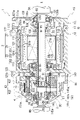
- the unit 1 as a 3-in-1 unit, includes a motor 2, a power transmission mechanism 3 that transmits the power output from the motor 2 to the drive wheels K, K of the vehicle, and a power conversion device for the motor 2. It has an inverter 7 (see FIG. 2).
- the unit 1 includes a power transmission mechanism 3, a planetary reduction gear 4 (reduction gear mechanism, planetary gear mechanism), a differential mechanism 5 (differential gear mechanism), and an output shaft. It has certain drive shafts DA, DB.
- a planetary reduction gear 4 reduction gear mechanism, planetary gear mechanism
- a differential mechanism 5 differential gear mechanism
- an output shaft It has certain drive shafts DA, DB.
- a planetary reduction gear 4 a differential mechanism 5, and drive shafts DA and DB are provided along a transmission path for output rotation of the motor 2 around the rotation axis X.
- Axes of the drive shafts DA and DB are coaxial with the rotation axis X of the motor 2
- the differential mechanism 5 is coaxial with the motor 2 .
- the output rotation of the motor 2 is decelerated by the planetary reduction gear 4 and input to the differential mechanism 5, and then transmitted through the drive shafts DA and DB to the left and right drive wheels of the vehicle on which the unit 1 is mounted. K, K is transmitted.
- the planetary reduction gear 4 is connected downstream of the motor 2 .
- a differential mechanism 5 is connected downstream of the motor 2 via a planetary reduction gear 4 .
- the drive shafts DA, DB are connected downstream of the differential mechanism 5 .
- the unit 1 has a housing HS that accommodates the motor 2, power transmission mechanism 3 and inverter 7 as a 3-in-1 type housing.
- the housing HS is composed of one or more cases.
- the housing HS has, for example, a motor case 10 that houses the motor 2 , a gear case 14 that houses the power transmission mechanism 3 , and an inverter case 17 that houses the inverter 7 .
- a gear case 14 is joined to one end side of the motor case 10 in the rotation axis X direction.
- the inverter case 17 is joined above the motor case 10 in the direction of gravity when the unit 1 is mounted on the vehicle.
- the inverter 7 is an electronic component including a smoothing capacitor, a power semiconductor element, a driver board, and the like.
- the inverter 7 is electrically connected to the motor 2 inside the motor case 10 by wiring (not shown).
- a cooling path CP2 through which cooling water CL (see FIG. 6) for cooling the inverter 7 flows is formed in the inverter case 17 .
- the motor 2 has a portion that overlaps the differential mechanism 5 (differential gear mechanism) when viewed in the axial direction (see FIG. 3).
- differential mechanism 5 differential gear mechanism
- “when viewed in the axial direction” means when viewed from the rotation axis X direction.
- “when viewed in the radial direction” means when viewed from the radial direction of the rotation axis X direction.
- the motor 2 has a portion that overlaps the planetary reduction gear 4 (reduction gear mechanism).
- the planetary reduction gear 4 (reduction gear mechanism) has a portion that overlaps the differential mechanism 5 (differential gear mechanism).
- the planetary reduction gear 4 (reduction gear mechanism) has a portion that overlaps the motor 2 .
- the differential mechanism 5 (differential gear mechanism) has a portion that overlaps the planetary reduction gear 4 (reduction gear mechanism).
- the differential mechanism 5 (differential gear mechanism) has a portion that overlaps the motor 2 when viewed in the axial direction.
- the motor 2 has a portion that overlaps the differential mechanism 5 (differential gear mechanism).
- the motor case 10 includes a first case member 11, a second case member 12 fitted around the first case member 11, and a cover member 13 joined to one end of the first case member 11.
- the first case member 11 has a cylindrical support wall portion 111 and a flange-like joint portion 112 provided at one end 111 a of the support wall portion 111 .
- the support wall portion 111 is provided along the rotation axis X of the motor 2 .
- the motor 2 is accommodated inside the support wall portion 111 .
- the second case member 12 includes a cylindrical peripheral wall portion 121, a flange-shaped joint portion 122 provided at one end 121a of the peripheral wall portion 121, and a flange-shaped joint portion 123 provided at the other end 121b of the peripheral wall portion 121. and have The peripheral wall portion 121 of the second case member 12 is formed with an inner diameter that allows it to be externally inserted into the support wall portion 111 of the first case member 11 .
- the first case member 11 and the second case member 12 are assembled together by externally inserting the peripheral wall portion 121 of the second case member 12 into the support wall portion 111 of the first case member 11 .
- the joint portion 122 on the one end 121a side of the peripheral wall portion 121 abuts the joint portion 112 of the first case member 11 from the rotation axis X direction.
- These joints 122 and 112 are connected to each other by bolts (not shown).
- a projection 111b is provided on the outer circumference of the support wall portion 111 of the first case member 11.
- the protrusion 111b is one wall that surrounds the rotation axis X at intervals.
- the protrusions 111b are spirally provided on the support wall portion 111 with a phase shift from one end to the other end in the direction of the rotation axis X.
- the projection 111b surrounds the outer circumference of the support wall portion 111 over the entire circumference of the support wall portion 111 .
- the peripheral wall portion 121 of the second case member 12 is fitted onto the support wall portion 111 of the first case member 11 .
- the inner periphery of the peripheral wall portion 121 is in contact with the outer periphery of the spiral projection 111b of the support wall portion 111, so that a space is formed between the peripheral wall portion 121 and the support wall portion 111.
- FIG. This space surrounds the rotation axis X at intervals and is formed in a helical shape continuous in the rotation axis X direction.
- This spiral space forms a cooling passage CP1 through which cooling water CL (see FIG. 6), which is a coolant, flows.
- the spiral cooling path CP1 is simplified and shown in a straight line.
- Ring grooves 111c, 111c are formed on both sides of the region where the protrusion 111b is provided on the outer periphery of the support wall portion 111 of the first case member 11. As shown in FIG. Seal rings 113, 113 are fitted in the ring grooves 111c, 111c. These seal rings 113 are pressed against the inner periphery of the peripheral wall portion 121 fitted on the support wall portion 111 to seal the gap between the outer periphery of the support wall portion 111 and the inner periphery of the peripheral wall portion 121 .
- the other end 121b of the second case member 12 is provided with a wall portion 120 (cover) extending radially inward.
- the wall portion 120 is provided in a direction perpendicular to the rotation axis X.
- An opening 120a through which the drive shaft DA is inserted is formed in a region of the wall portion 120 that intersects with the rotation axis X.
- a cylindrical motor support portion 125 that surrounds the opening 120a and extends toward the motor 2 is provided on the surface of the wall portion 120 on the motor 2 side (right side in the figure).
- the motor support portion 125 is inserted inside a coil end 253b, which will be described later.
- the motor support portion 125 faces the end portion 21b of the rotor core 21 with a gap in the rotation axis X direction.
- a bearing B ⁇ b>1 is supported on the inner circumference of the motor support portion 125 .
- the outer circumference of the motor shaft 20 is supported by a motor support portion 125 via a bearing B1.
- a cylindrical wall portion 126 extending toward the differential mechanism 5 is provided on the surface of the wall portion 120 on the side of the differential mechanism 5 (on the left side in the figure).
- the cylindrical wall portion 126 has a cylindrical shape surrounding the opening 120a, and the inner circumference of the cylindrical wall portion 126 supports a bearing B2.
- the bearing B2 supports a tubular wall portion 61 of the differential case 50, which will be described later.
- the cover member 13 has a wall portion 130 perpendicular to the rotation axis X and a joint portion 132 .
- the cover member 13 When viewed from the first case member 11, the cover member 13 is located on the side opposite to the differential mechanism 5 (on the right side in the drawing).
- the joint portion 132 of the cover member 13 is joined to the joint portion 112 of the first case member 11 from the rotation axis X direction.
- the cover member 13 and the first case member 11 are connected to each other with bolts (not shown). In this state, the cover member 13 closes the opening of the support wall portion 111 on the joint portion 122 side (right side in the drawing) of the first case member 11 .
- an insertion hole 130a for the drive shaft DA is provided in the central portion of the wall portion 130.
- a lip seal RS is provided on the inner circumference of the insertion hole 130a.
- the lip seal RS brings the lip portion (not shown) into elastic contact with the outer circumference of the drive shaft DA.
- a gap between the inner periphery of the insertion hole 130a and the outer periphery of the drive shaft DA is sealed with a lip seal RS.
- a peripheral wall portion 131 surrounding the insertion hole 130a is provided on the surface of the wall portion 130 on the side of the first case member 11 (left side in the figure).
- a drive shaft DA is supported on the inner periphery of the peripheral wall portion 131 via a bearing B4.
- a motor support portion 135 and a connection wall 136 are provided on the inner diameter side of the joint portion 132 .
- the motor support portion 135 is provided on the motor 2 side (left side in the figure) when viewed from the peripheral wall portion 131 .
- the motor support portion 135 has a tubular shape surrounding the rotation axis X with a space therebetween.
- a cylindrical connection wall 136 is connected to the outer periphery of the motor support portion 135 .
- the connection wall 136 is formed with a larger outer diameter than the peripheral wall portion 131 on the wall portion 130 side (right side in the drawing).
- the connection wall 136 is oriented along the rotation axis X and extends away from the motor 2 .
- the connection wall 136 connects the motor support portion 135 and the joint portion 132 .
- One end 20a side of the motor shaft 20 penetrates the inside of the motor support portion 135 from the motor 2 side to the peripheral wall portion 131 side.
- a bearing B ⁇ b>1 is supported on the inner periphery of the motor support portion 135 .
- the outer circumference of the motor shaft 20 is supported by a motor support portion 135 via a bearing B1.
- a lip seal RS is provided at a position adjacent to the bearing B1.
- Oil holes 136 a and 136 b are opened on the inner periphery of the connection wall 136 .
- the oil OL flows into the space (internal space Sc) surrounded by the connection wall 136 through the oil hole 136a.
- the oil OL that has flowed into the internal space Sc is discharged from the oil hole 136b.
- the lip seal RS is provided to prevent the oil OL in the connection wall 136 from flowing into the motor 2 side.
- the gear case 14 has a peripheral wall portion 141 and a flange-like joint portion 142 provided at the end portion of the peripheral wall portion 141 on the motor case 10 side.
- a support portion 145 for a bearing B2 which will be described later, is provided at an end portion of the peripheral wall portion 141 on the side opposite to the joint portion 142 (on the left side in the drawing).
- the peripheral wall portion 141 includes a cylindrical wall portion 141a connected to the joint portion 142, an inclined portion 141c (wall portion) connected to the support portion 145, and a connecting wall portion 141b connecting the cylindrical wall portion 141a and the inclined portion 141c.
- the tubular wall portion 141a and the connecting wall portion 141b are gradually reduced in diameter from the joint portion 142 and connected to the inclined portion 141c.
- the inclined portion 141c is inclined radially inward from the connecting wall portion 141b toward the support portion 145 .
- the planetary reduction gear 4 and the differential mechanism 5 which are the power transmission mechanism 3 are housed inside the peripheral wall portion 141 .
- the gear case 14 is positioned on the differential mechanism 5 side (left side in the figure) when viewed from the motor case 10 .
- the joint portion 142 of the gear case 14 is joined to the joint portion 123 of the second case member 12 of the motor case 10 from the rotation axis X direction.
- the gear case 14 and the second case member 12 are connected to each other by bolts (not shown).
- the space formed inside the joined motor case 10 and gear case 14 is partitioned into two by the wall portion 120 (cover) of the second case member 12 .
- the wall portion 120 on the motor case 10 side is the motor chamber Sa that houses the motor 2
- the gear case 14 side is the gear chamber Sb that houses the power transmission mechanism 3 .
- a wall portion 120 as a cover is sandwiched between the motor 2 and the differential mechanism 5 inside the housing HS.
- the cover may have a portion housed within the housing HS, and may be wholly housed in the housing HS like the wall section 120 . Also, the cover may be separate from the second case member 12, for example. In this case, the cover may be sandwiched between the motor case 10 and the gear case 14 and fixed. A part of the cover may be exposed outside the housing HS.
- the motor 2 has a cylindrical motor shaft 20, a cylindrical rotor core 21 fitted onto the motor shaft 20, and a stator core 25 surrounding the outer circumference of the rotor core 21 with a gap.
- bearings B ⁇ b>1 and B ⁇ b>1 are externally inserted and fixed on both sides of the rotor core 21 .
- a bearing B ⁇ b>1 positioned on the one end 20 a side (right side in the drawing) of the motor shaft 20 when viewed from the rotor core 21 is supported on the inner periphery of the motor support portion 135 of the cover member 13 .
- a bearing B ⁇ b>1 located on the other end 20 b side (left side in the drawing) is supported on the inner circumference of a cylindrical motor support portion 125 of the second case member 12 .
- the motor support portions 135 and 125 are arranged to face one end portion 21a and the other end portion 21b of the rotor core 21 with a gap in the rotation axis X direction on the inner diameter side of coil ends 253a and 253b, which will be described later. ing.
- the rotor core 21 is formed by laminating a plurality of silicon steel plates. Each of the silicon steel plates is fitted over the motor shaft 20 in a state where relative rotation with the motor shaft 20 is restricted.
- the silicon steel plate has a ring shape when viewed from the rotation axis X direction of the motor shaft 20 .
- N-pole and S-pole magnets are provided alternately in the circumferential direction around the rotation axis X on the outer peripheral side of the silicon steel plate.
- a stator core 25 surrounding the outer periphery of the rotor core 21 is formed by laminating a plurality of electromagnetic steel sheets.
- the stator core 25 is fixed to the inner periphery of the cylindrical support wall portion 111 of the first case member 11 .
- Each of the electromagnetic steel sheets has a ring-shaped yoke portion 251 fixed to the inner periphery of the support wall portion 111 and tooth portions 252 protruding from the inner periphery of the yoke portion 251 toward the rotor core 21 side.
- stator core 25 having a configuration in which the windings 253 are distributed over a plurality of teeth 252 is adopted.
- the stator core 25 is longer than the rotor core 21 in the direction of the rotation axis X by the coil ends 253a and 253b projecting in the direction of the rotation axis X. As shown in FIG.
- a stator core in which windings are concentratedly wound may be employed for each of the plurality of tooth portions 252 protruding toward the rotor core 21 side.
- the wall portion 120 (motor support portion 125) of the second case member 12 is provided with an opening 120a.
- the other end 20b side of the motor shaft 20 passes through the opening 120a to the differential mechanism 5 side (left side in the figure) and is positioned inside the gear case 14 .
- the other end 20b of the motor shaft 20 faces a side gear 54A, which will be described later, with a gap in the rotation axis X direction.
- a lip seal RS is inserted between the motor shaft 20 and the opening 120 a of the wall portion 120 .
- Oil OL for lubricating the planetary reduction gear 4 and the differential mechanism 5 is enclosed in the inner diameter side of the gear case 14 .
- Lip seal RS is provided to prevent oil OL in gear case 14 from flowing into motor case 10 .
- the sun gear 41 of the planetary reduction gear 4 is spline-fitted to the region of the motor shaft 20 located within the gear case 14 .
- a toothed portion 41a is formed on the outer periphery of the sun gear 41, and a large-diameter gear portion 431 of the stepped pinion gear 43 is meshed with the toothed portion 41a.
- the stepped pinion gear 43 has a large-diameter gear portion 431 (large pinion) that meshes with the sun gear 41 and a small-diameter gear portion 432 (small pinion) having a smaller diameter than the large-diameter gear portion 431 .
- the large-diameter gear portion 431 and the small-diameter gear portion 432 are integral gear components arranged side by side in the direction of the axis X1 parallel to the rotation axis X. As shown in FIG.
- the outer circumference of the small diameter gear portion 432 meshes with the inner circumference of the ring gear 42 .
- the ring gear 42 has a ring shape surrounding the rotation axis X with a space therebetween. Engagement teeth are provided on the outer periphery of the ring gear 42, and the engagement teeth are spline-fitted to tooth portions 146a provided on the inner periphery of the connection wall portion 141b. The rotation of the ring gear 42 around the rotation axis X is restricted.
- the pinion shaft 44 passes through the inner diameter side of the large-diameter gear portion 431 and the small-diameter gear portion 432 .
- the stepped pinion gear 43 is rotatably supported on the outer circumference of the pinion shaft 44 via needle bearings NB, NB.
- the differential mechanism 5 has a differential case 50 (differential case) as an input element, drive shafts DA and DB (output shafts) as output elements, and a differential gear set as a differential element.
- the differential case 50 may be composed of two case members assembled in the rotation axis direction.
- the differential case 50 also functions as a carrier that supports the stepped pinion gear 43 of the planetary reduction gear 4.
- the stepped pinion gear 43 is rotatably supported by the differential case 50 via the pinion shaft 44 .
- the three stepped pinion gears 43 are circumferentially spaced around the rotation axis X. As shown in FIG.
- a pinion mate gear 52 which is a bevel gear type differential gear, and side gears 54A and 54B are provided as a differential gear set.
- the pinion mate gear 52 is supported by the pinion mate shaft 51 .
- the pinion mate shaft 51 has a central member 510 arranged on the rotation axis X and a shaft member 511 connected to the outer diameter side of the central member 510 .
- a plurality of shaft members 511 are provided in the circumferential direction around the rotation axis X at equal intervals.
- the shaft member 511 is inserted through a radially extending support hole 69 of the differential case 50 and supported.
- the pinion mate gears 52 are fitted one by one onto each of the shaft members 511 and are rotatably supported.
- the side gear 54A is positioned on one side of the central member 510 in the direction of the rotation axis X, and the side gear 54B is positioned on the other side.
- the side gears 54A, 54B are rotatably supported by the differential case 50, respectively.
- the side gear 54A meshes with the pinion mate gear 52 from one side in the rotation axis X direction.
- the side gear 54B meshes with the pinion mate gear 52 from the other side in the rotation axis X direction.
- An opening 60 and a cylindrical wall portion 61 surrounding the opening 60 and extending toward the motor case 10 are provided in the central portion of one end side (right side in the drawing) of the differential case 50 .
- the outer circumference of the cylinder wall portion 61 is supported by the wall portion 120 of the second case member 12 via the bearing B2.
- a drive shaft DA passing through an opening 60 is inserted into the differential case 50 from the rotation axis X direction.
- the drive shaft DA passes through the insertion hole 130a of the wall portion 130 of the cover member 13, and is provided across the inner diameter side of the motor shaft 20 of the motor 2 and the sun gear 41 of the planetary reduction gear 4 in the rotation axis X direction. .
- a through hole 65 and a cylindrical wall portion 66 surrounding the through hole 65 are formed in the center of the other end side (left side in the drawing) of the differential case 50 .
- a bearing B ⁇ b>2 is fitted on the cylindrical wall portion 66 .
- the bearing B ⁇ b>2 externally inserted into the cylinder wall portion 66 is held by the support portion 145 of the gear case 14 .
- a tubular wall portion 66 of the differential case 50 is rotatably supported by the gear case 14 via a bearing B2.
- a drive shaft DB passing through an opening 145a of the gear case 14 is inserted into the support portion 145 from the rotation axis X direction.
- Drive shaft DB is rotatably supported by support portion 145 .
- the cylinder wall portion 66 functions as a shaft support portion that supports the outer circumference of the drive shaft DB.
- a lip seal RS is fixed to the inner circumference of the opening 145a.
- a lip portion (not shown) of the lip seal RS is in elastic contact with the outer circumference of the cylinder wall portion 540 of the side gear 54B externally fitted on the drive shaft DB. As a result, the gap between the outer circumference of the cylindrical wall portion 540 of the side gear 54B and the inner circumference of the opening 145a is sealed.
- the side gears 54A and 54B are arranged opposite to each other with a gap in the rotation axis X direction.
- a central member 510 of the pinion mate shaft 51 is positioned between the side gears 54A, 54B.
- the pinion mate gear 52 is assembled to a side gear 54A positioned on one side in the direction of the rotation axis X and a side gear 54B positioned on the other side in such a manner that the teeth thereof are meshed with each other.
- a support hole 62 on the one end 44a side of the pinion shaft 44 is formed on the outer diameter side of the opening 60 on the one end side (right side in the drawing) of the differential case 50 .
- a support hole 68 on the side of the other end 44b of the pinion shaft 44 is formed in the other end side of the differential case 50 (left side in the drawing).
- the support holes 62 and 68 are formed at overlapping positions in the rotation axis X direction.
- the support holes 62 and 68 are formed at intervals in the circumferential direction around the rotation axis X so as to match the position where the stepped pinion gear 43 is arranged.
- One end 44 a of the pinion shaft 44 is inserted into the support hole 62 and the other end 44 b is inserted into the support hole 68 .
- the other end 44 b of the pinion shaft 44 is press-fitted into the support hole 68 so that the pinion shaft 44 is fixed to the differential case 50 so as not to rotate relative to it.
- a stepped pinion gear 43 externally fitted on the pinion shaft 44 is rotatably supported around an axis X1 parallel to the rotation axis X. As shown in FIG.
- lubricating oil OL is stored inside the gear case 14 .
- the differential case 50 rotates around the rotation axis X, the oil OL is scraped up by the differential case 50 .
- the differential case 50, the pinion shaft 44, and the like are provided with oil passages, oil holes, and the like for introducing the oil OL that has been raked up by the differential case 50. As shown in FIG. This makes it easier for the oil OL to be introduced into rotating members such as the bearing B2 and the needle bearing NB.
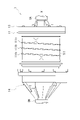
- a catch tank 15 is provided above the differential case 50 inside the gear case 14 .
- the catch tank 15 is positioned on one side (left side in the drawing) of a vertical line VL perpendicular to the rotation axis X.
- the catch tank 15 and the accommodation portion 140 of the differential case 50 communicate with each other through a communication port 147 . Some of the oil OL that has been scraped up and scattered by the differential case 50 flows into the catch tank 15 from the communication port 147 and is collected.
- the differential case 50 rotates about the rotation axis X in the counterclockwise direction CCW when viewed from the motor case 10 side.
- the small diameter gear portion 432 of the stepped pinion gear 43 meshes with the ring gear 42 fixed to the inner circumference of the gear case 14 . Therefore, the large-diameter gear portion 431 of the stepped pinion gear 43 revolves around the rotation axis X in the counterclockwise direction CCW while rotating clockwise around the axis X1, as shown in FIG.
- the catch tank 15 is located on the left side of the vertical line VL, that is, on the downstream side in the rotational direction of the differential case 50 . As a result, most of the oil OL that has been raked up by the differential case 50 rotating around the rotation axis X can flow into the catch tank 15 .
- the catch tank 15 is connected to the space Rx between the lip seal RS and the bearing B2 via an oil passage 151a.
- the catch tank 15 is connected to an oil cooler 83 (see FIG. 6) via an oil passage, piping, etc., not shown.
- the oil cooler 83 is connected to an oil hole 136a (see FIG. 3) formed in the connection wall 136 via a pipe, an oil passage and the like (not shown). Note that FIG. 3 shows the catch tank 15 in phantom lines for the sake of explanation, and does not reflect the actual position of the catch tank 15 .
- An oil hole Ha is formed in the peripheral wall portion 141 of the gear case 14 .
- the oil hole Ha is connected via a pipe (not shown) to an oil hole 136b formed in the internal space Sc.
- the oil OL discharged from the internal space Sc through the oil hole 136b is re-supplied into the gear chamber Sb through the oil hole Ha.
- a cooling chamber 9 is provided in the inclined portion 141c (wall portion) of the gear case 14. As shown in FIG. 6, inside the cooling chamber 9, a cooling passage CP3 through which the cooling water CL flows is provided inside the cooling chamber 9, a cooling passage CP3 through which the cooling water CL flows is provided. The cooling water CL that has flowed through the cooling path CP1 of the motor case 10 is introduced into the cooling path CP3.
- the unit 1 is provided with a circulation system 80 for cooling water CL.
- the circulation system 80 circulates the cooling water CL between the cooling path CP ⁇ b>1 of the motor case 10 , the cooling path CP ⁇ b>2 of the inverter case 17 , and the cooling path CP ⁇ b>3 of the cooling chamber 9 .
- the circulation system 80 further includes an oil cooler 83, a water pump WP, and a radiator 82 between the cooling paths CP3 and CP2, which are connected by piping or the like through which the cooling water CL flows.
- the water pump WP pumps the cooling water CL through the circulation system 80 .
- the radiator 82 is a device that dissipates the heat of the cooling water CL to cool it.
- the oil cooler 83 is a heat exchanger that exchanges heat between the cooling water CL and the oil OL.
- the oil OL collected by the catch tank 15 provided in the gear chamber Sb of the gear case 14 is introduced into the oil cooler 83 .
- Oil OL is cooled by heat exchange with cooling water CL.
- the cooled oil OL is supplied from the oil hole 136a of the motor case 10 to the internal space Sc.
- the oil OL to be supplied to the oil cooler 83 is not limited to the oil OL collected by the catch tank 15, and may be supplied from another oil passage appropriately provided in the housing HS. Also, the oil OL discharged from the oil cooler 83 may be supplied to a location other than the internal space Sc.
- the cooling water CL is supplied to the oil cooler 83 after flowing through the cooling passage CP3 of the cooling chamber 9 . After the cooling water CL is heat-exchanged with the oil OL in the oil cooler 83, it is cooled by the radiator 82 and supplied to the cooling path CP2 of the inverter case 17 again.
- the cooling chamber 9 is provided on the inclined portion 141 c (wall portion) of the gear case 14 .
- the inclined portion 141c has a truncated cone shape that decreases in diameter in a direction away from the motor case 10 .
- the space around the inclined portion 141c is larger than the space around the motor case 10 of the unit 1, etc., because the diameter of the gear case 14 is reduced.
- the cooling chamber 9 is arranged in the space around the inclined portion 141c. The configuration of the cooling chamber 9 will be described below.
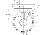
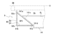
- FIG. 8 is a diagram of the gear case 14 viewed from the rotation axis X direction.
- FIG. 9 is a cross-sectional view of the main body 90 of the cooling chamber 9 taken along line AA in FIG. Note that in FIG. 9, the gear case 14 and the drive shaft DB are indicated by phantom lines for convenience of explanation.
- FIG. 10 is a diagram for explaining the cooling path CP3 inside the cooling chamber 9. As shown in FIG. In FIG. 10, the inside of the cooling chamber 9 is indicated by broken lines.
- FIG. 11 is a schematic diagram of the AA section of FIG. FIG. 11 shows the inside of the gear case 14 in a simplified manner.
- the cooling chamber 9 is arranged adjacent to the catch tank 15 provided on the top of the gear case 14 .
- the cooling chamber 9 has a body portion 90 (arc-shaped portion) that is an arc-shaped member when viewed from the rotation axis X direction.
- the body portion 90 is arranged in the circumferential direction around the rotation axis X so as to surround the drive shaft DB, and is joined to the inclined portion 141c.
- the body portion 90 is joined to an end portion 141d of the inclined portion 141c on the motor case 10 side (right side in the drawing) and an end portion 141e on the opposite side (left side in the drawing).
- the body portion 90 has a first wall portion 91 and a second wall portion 92 .
- One end 91a of the first wall portion 91 is joined to one end 141d of the inclined portion 141c.
- the first wall portion 91 extends along the rotation axis X direction.
- the other end portion 91b of the first wall portion 91 is spaced from the inclined portion 141c.
- One end portion 92a of the second wall portion 92 is joined to the end portion 141e.
- the second wall portion 92 extends radially outward of the rotation axis X. As shown in FIG.
- the second wall portion 92 is provided in a direction substantially perpendicular to the rotation axis X when the main body portion 90 is attached to the gear case 14 .
- the other end 92b of the second wall 92 connects to the end 91b of the first wall 91 .
- the cooling chamber 9 has a triangular space surrounded by the first wall portion 91 and the second wall portion 92 of the main body portion 90 and the inclined portion 141c in cross-sectional view. .
- This space constitutes a cooling passage CP3 through which cooling water CL, which is coolant, flows. That is, the cooling path CP3, which is a flow path for coolant, is a portion integrally formed with the housing HS.
- the inclined portion 141c forms part of the wall surface of the catch tank 15 formed inside the gear case 14. As shown in FIG. That is, the cooling path CP3 and the catch tank 15 are adjacent to each other with the inclined portion 141c interposed therebetween.
- the cooling path CP3 when viewed from the rotation axis X direction, extends from one side of the vertical line VL perpendicular to the rotation axis X to the other side of the vertical line VL via below the rotation axis X. It forms an arc that extends to One end and the other end in the longitudinal direction of the cooling path CP3 are closed by the third wall portion 93 of the main body portion 90, respectively.
- the third wall portions 93, 93 are connected across the first wall portion 91, the second wall portion 92, and the wall surface of the inclined portion 141c.
- the cooling path CP3 has an arc shape surrounding the rotation axis X when viewed from the rotation axis X direction.
- the cooling path CP3 has a portion positioned above and a portion positioned below a horizontal plane S passing through the rotation axis X and perpendicular to the vertical line VL.
- the introduction portion 95 has an opening portion 95a penetrating through the first wall portion 91 of the main body portion 90, and a peripheral wall portion 95b surrounding the opening portion 95a and extending upward in the direction of the vertical line VL.
- the introduction part 95 communicates with one end side (right side in the drawing) of the cooling path CP3 in the circumferential direction around the rotation axis X through the opening 95a.
- the discharge portion 96 is composed of an opening 96a provided through the first wall portion 91 of the main body portion 90, and a peripheral wall portion 96b surrounding the opening 96a and extending upward in the direction of the vertical line VL.
- the discharge portion 96 communicates with the other end side (the left side in the figure) of the cooling path CP3 in the circumferential direction around the rotation axis X through the opening portion 96a.
- the introduction part 95 and the discharge part 96 are positioned above the horizontal plane S.
- the cooling path CP3 has a portion positioned above the horizontal plane S and connected to the introduction portion 95 and the discharge portion 96, and a portion positioned below.
- the introduction portion 95 is connected to the discharge portion 96 via a portion located below the horizontal plane S of the cooling path CP3.
- a peripheral wall portion 95b of the introduction portion 95 is connected to the cooling path CP1 (see FIG. 6) of the motor case 10 via a pipe or the like (not shown).
- a peripheral wall portion 96b of the discharge portion 96 is connected to the radiator 82 (see FIG. 6) via a pipe or the like (not shown).
- the catch tank 15 is positioned on one side of the vertical line VL along which the introduction portion 95 is arranged when viewed from the rotation axis X direction.
- the inner surface of the inclined portion 141c contacts the oil OL stored in the catch tank 15 above the rotation axis X. As shown in FIG. As shown in FIG. 9, the inner surface of the inclined portion 141c contacts the oil OL stored in the gear chamber Sb below the rotation axis X. As shown in FIG. On the other hand, the outer surface of the inclined portion 141c is in contact with the cooling water CL introduced into the cooling path CP3. That is, heat exchange can be performed between the oil OL inside the gear case 14 and the cooling water CL in the cooling path CP3 via the inclined portion 141c, which is the wall portion.
- a planetary reduction gear 4 As shown in FIG. 1 , in the unit 1 , a planetary reduction gear 4 , a differential mechanism 5 , and drive shafts DA and DB are provided along the output rotation transmission path of the motor 2 .
- the sun gear 41 serves as an input portion for the output rotation of the motor 2
- the differential case 50 that supports the stepped pinion gear 43 serves as an output portion for the input rotation.
- the stepped pinion gear 43 (the large-diameter gear portion 431 and the small-diameter gear portion 432) is rotated by the rotation input from the sun gear 41 side. , and rotates around the axis X1.
- the small diameter gear portion 432 of the stepped pinion gear 43 meshes with the ring gear 42 fixed to the inner circumference of the gear case 14 . Therefore, the stepped pinion gear 43 revolves around the rotation axis X while rotating around the axis X1.
- the outer diameter of the small-diameter gear portion 432 is smaller than the outer diameter of the large-diameter gear portion 431 .
- the differential case 50 supporting the stepped pinion gear 43 rotates around the rotation axis X at a rotation speed lower than the rotation input from the motor 2 side. Therefore, the rotation input to the sun gear 41 of the planetary reduction gear 4 is greatly reduced by the stepped pinion gear 43 and then output to the differential case 50 (differential mechanism 5).
- lubricating oil OL is stored inside the gear chamber Sb.
- the stored oil OL is scooped up by the differential case 50 rotating around the rotation axis X when the output rotation of the motor 2 is transmitted.
- the raking oil OL causes the meshing portion between the sun gear 41 and the large-diameter gear portion 431 , the meshing portion between the small-diameter gear portion 432 and the ring gear 42 , and the pinion mate gear 52 . and the meshing portions with the side gears 54A and 54B are lubricated.
- the differential case 50 rotates about the rotation axis X in the counterclockwise direction CCW.
- a catch tank 15 is provided above the gear case 14 .
- the catch tank 15 is located downstream of the differential case 50 in the rotation direction, and part of the oil OL that has been scraped up by the differential case 50 flows into the catch tank 15 .
- part of the oil OL that has flowed into the catch tank 15 is supplied to the space Rx between the lip seal RS and the bearing B2 via the oil passage 151a to lubricate the bearing B2.
- a portion of the oil OL that has flowed into the catch tank 15 is introduced into the oil cooler 83 via an oil passage, piping, etc., not shown, and is cooled by heat exchange with the cooling water CL.
- the cooled oil OL is discharged from the oil cooler 83 and supplied to the internal space Sc (see FIG. 3) formed in the connection wall 136 via oil passages, piping, etc. (not shown).
- the oil OL supplied to the internal space Sc lubricates the bearings B1 and B4 and is discharged from the oil hole 136b.
- the oil OL discharged from the oil hole 136b is supplied from the oil hole Ha into the gear chamber Sb via a pipe or the like (not shown).
- the gear case 14 of the housing HS has an inclined portion 141c as a wall portion surrounding the rotation axis X of the differential mechanism 5 in the radial direction.
- the cooling chamber 9 is arranged in this inclined portion 141c.
- a cooling path CP3 is provided inside the cooling chamber 9 .
- the cooling water CL that has flowed through the cooling path CP2 (see FIG. 6) is introduced into the cooling path CP3 via the peripheral wall portion 95b and the opening 95a of the introduction portion 95.
- the cooling water CL introduced to one end side of the cooling path CP3 in the longitudinal direction flows toward the discharge portion 96 on the other end side of the cooling path CP3.
- the inclined portion 141c forms part of the cooling path CP3. That is, the outer surface of the inclined portion 141c is in contact with the cooling water CL flowing through the cooling path CP3. Heat exchange between the inclined portion 141c and the cooling path CP3 reduces the temperature rise of the gear case 14 of the housing HS.
- the inner surface of the inclined portion 141c is in contact with the oil OL of the gear chamber Sb. Specifically, the inner surface of the inclined portion 141c is in contact with the oil OL stored in the catch tank 15 above the rotation axis X (above the horizontal plane S in FIG. 8) (see FIG. 11). The inner surface of the inclined portion 141c is in contact with the oil OL stored in the lower portion of the gear chamber Sb below the rotation axis X (below the horizontal plane S in FIG. 8).
- the inclined portion 141c is in contact with the oil OL, so that the heat of the oil OL is transferred to the inclined portion 141c. That is, heat exchange is performed between the oil OL in the gear chamber Sb and the cooling water CL flowing through the cooling path CP3 via the inclined portion 141c.
- the oil OL the temperature of which has risen due to heat exchange with parts inside the gear chamber Sb, is cooled by performing heat exchange with the cooling water CL whose temperature is lower than that of the oil OL.
- the cooling water CL that has exchanged heat with the oil OL is discharged from the cooling path CP3 through the opening 96a and the peripheral wall portion 96b of the discharge portion 96.
- the cooling water CL discharged from the cooling path CP3 is cooled by the radiator 82 (see FIG. 6) and then supplied to the cooling path CP2.
- the cooling chamber 9 forming the cooling path CP3 is arranged at a position overlapping the inclined portion 141c of the housing HS in the rotation axis X direction. Arranging the cooling chamber 9 by making use of the space around the inclined portion 141c contributes to reducing the dimension of the unit 1 in the radial direction of the rotation axis X.
- the cooling chamber 9 arranged to surround the inclined portion 141c overlaps the inclined portion 141c in the radial direction of the rotation axis X. As shown in FIG. This also contributes to reduction of the dimension of the unit 1 in the direction of the rotation axis X.
- the main body 90 of the cooling chamber 9 has a portion located above a horizontal plane S passing through the rotation axis X and orthogonal to the vertical line VL direction. Further, as shown in FIG. 2 , the body portion 90 has a portion positioned above the differential mechanism 5 in the vertical line VL direction. Further, the body portion 90 has a portion that overlaps the stepped pinion gear 43 in the rotation axis X direction. Thus, the body portion 90 of the cooling chamber 9 has a portion positioned above the unit 1 in the direction of the vertical line VL.
- the motor 2 and the differential mechanism 5 are coaxial, and the differential mechanism 5 has a portion that overlaps the motor 2 when viewed in the rotation axis X direction.
- layout restrictions are looser above the vertical line VL direction (vehicle height direction) than below the vertical line VL direction (vehicle height direction). Since the main body 90 of the cooling chamber 9 has a portion positioned above the unit 1 with loose layout restrictions in the direction of the vertical line VL, it is possible to increase the flow area of the cooling water CL in the cooling path CP3. As a result, the area of contact between the cooling water CL and the outer surface of the inclined portion 141c is increased, and the heat exchange rate with the oil OL can be improved.
- An introduction portion 95 for the cooling water CL located above the horizontal plane S is connected to the discharge portion 96 via a cooling passage CP3 having a portion located below the horizontal surface S.
- the cooling water CL introduced from the introduction portion 95 into the cooling path CP3 can flow to the discharge portion 96 using gravity.
- the circulation system 80 (see FIG. 6) is provided with the water pump WP for pressure-feeding the cooling water CL. By utilizing gravity, the cooling water CL can be circulated more smoothly. .
- the cooling chamber 9 is arranged adjacent to the catch tank 15, and the catch tank 15 is located on the introduction part 95 side of the cooling water CL.
- the temperature of the cooling water CL increases as it flows through the cooling path CP3 and exchanges heat with the oil OL.
- the cooling water CL on the introduction portion 95 side before heat exchange is lower in temperature than the cooling water CL on the discharge portion 96 side.
- the unit 1 may be placed on the rear side of the vehicle where it is less likely to be affected by the running wind of the vehicle. As shown in FIG. 8, when the unit 1 is mounted on the vehicle, a vehicle interior VR is arranged above the space SP in which the unit 1 is arranged. The vehicle is provided with a vent VP that communicates the space SP in which the unit 1 is arranged and the vehicle interior VR.
- the air Air in the vehicle interior VR is discharged from the vent VP and flows into the space SP.
- the temperature of the air Air in the vehicle interior VR is adjusted according to the outside air temperature. For example, air conditioning is used in vehicles or windows are opened when the outside temperature is high. Also, for example, heating is used when the outside temperature is low.
- the air Air whose temperature is adjusted according to the outside air temperature flows into the space SP, it exchanges heat with the housing HS arranged in the space SP.
- the cooling chamber 9 attached to the housing HS can also exchange heat with the air Air.
- the heat exchange efficiency between the cooling water CL flowing through the cooling chamber 9 and the oil OL inside the housing HS is improved.
- the cooling chamber 9 can be made smaller, which contributes to the reduction of the size of the entire housing HS.
- a fan or the like may be provided so that the air Air in the vehicle interior VR can easily flow into the space SP.
- Unit 1 is It has a housing HS that accommodates the differential mechanism 5 (differential gear mechanism).
- the housing HS has a cooling path CP3 as a flow path through which cooling water CL (coolant) flows.
- the cooling path CP3 has a portion that overlaps the differential mechanism 5 .
- the cooling path CP3 has a portion located above a horizontal plane S passing through a rotation axis X coaxial with the axis of the drive shaft DB, which is the output shaft of the differential mechanism 5, and orthogonal to the vertical line VL direction (gravitational direction). have.
- the heat exchange efficiency between the housing HS and the cooling water CL which is the coolant, can be improved.
- the area around the differential mechanism 5 above the horizontal plane S has loose layout restrictions and has a margin of space. This space is utilized to arrange the cooling chamber 9 having the cooling path CP3. As a result, the contact area between the housing HS and the cooling water CL flowing through the cooling path CP3 is increased, and the heat exchange efficiency between the cooling water CL and the housing HS is improved.
- the cooling path CP3 has a portion located below the horizontal plane S.
- the cooling chamber 9 provided with the cooling path CP3 has a part located below the horizontal plane S in addition to the part located above the horizontal plane S. As a result, the contact area between the housing HS and the cooling water CL flowing through the cooling path CP3 is increased, and the heat exchange efficiency between the cooling water CL and the housing HS is improved.
- the cooling path CP3 When viewed in the direction of the rotation axis X (axially), the cooling path CP3 has a portion that overlaps the housing HS.
- the cooling path CP3 is less likely to protrude from the housing HS in the radial direction of the rotation axis X, which contributes to the size reduction of the unit 1.
- the arc-shaped portion (main body portion 90) arranged so as to surround the rotation axis X, which is the axial center of the drive shaft DB, which is the output shaft of the differential mechanism 5. have a shape that contains
- the cooling chamber 9 By forming the body portion 90 of the cooling chamber 9 as an arc-shaped portion and joining it to the inclined portion 141c so as to surround the rotation axis X, the cooling chamber 9 is larger than the unit 1 while maintaining the flow passage area of the cooling path CP3. Since the protrusion is reduced, it contributes to the size reduction of the unit 1 .
- the housing HS has, above the horizontal plane S, an inclined portion 141c (wall portion) having an outer surface in contact with the cooling water CL and an inner surface in contact with the oil OL.
- the inclined portion 141c constitutes a part of the cooling path CP3 and contacts the cooling water CL on its outer surface.
- the inner surface of the inclined portion 141c constitutes the wall surface of the catch tank 15 and is in contact with the oil OL. Since heat is exchanged between the cooling water CL and the oil OL via the wall surface of the inclined portion 141c, heat exchange efficiency is improved.
- the inclined portion 141c (wall portion) is configured as a part of the catch tank 15 to which the oil OL is supplied has been described, but it is not limited to this.
- a part of the oil passage through which the oil OL flows in the housing HS, a wall portion of the housing HS to which the oil OL is supplied while being guided by an oil guide, and the like can be used as the wall portion.
- the power transmission mechanism 3 has, for example, a gear mechanism, an annular mechanism, or the like.
- the gear mechanism includes, for example, a reduction gear mechanism, an increase gear mechanism, a differential gear mechanism (differential mechanism), and the like.
- the reduction gear mechanism and the acceleration gear mechanism have, for example, a planetary gear mechanism, a parallel gear mechanism, and the like.
- the annular mechanism has, for example, an endless annular component or the like. Endless annular parts and the like include, for example, chain sprockets, belts and pulleys, and the like.
- the differential mechanism 5 is, for example, a bevel gear type differential gear, a planetary gear type differential gear, or the like.
- the differential mechanism 5 has a differential case that is an input element, two output shafts that are output elements, and a differential gear set that is a differential element.
- the differential gear set In a bevel gear type differential gear, the differential gear set has bevel gears.
- the differential gear set In a planetary gear type differential gear, the differential gear set has planetary gears.
- the unit 1 has a gear that rotates integrally with the differential case.
- a final gear (differential ring gear) of the parallel gear mechanism rotates integrally with the differential case.
- the pinion gear rotates (revolves) integrally with the differential case.
- a reduction gear mechanism is connected downstream of the motor 2 .
- a differential gear mechanism is connected downstream of the reduction gear mechanism. That is, a differential gear mechanism is connected downstream of the motor 2 via a reduction gear mechanism.
- a speed increasing gear mechanism may be used instead of the speed reducing gear mechanism.
- a single-pinion planetary gear mechanism can use, for example, a sun gear as an input element, a ring gear as a fixed element, and a carrier as an output element.
- a double-pinion planetary gear mechanism can have, for example, a sun gear as an input element, a ring gear as an output element, and a carrier as a fixed element.
- a stepped pinion gear, a non-stepped pinion gear, or the like can be used as the pinion gear of the single pinion type or double pinion type planetary gear mechanism.
- a stepped pinion gear has a large pinion and a small pinion. For example, it is preferable to mesh the large pinion with the sun gear. For example, it is preferable to fit the small pinion to the ring gear.
- a non-stepped pinion gear is a type that is not a stepped pinion gear.
- Cooling chamber 90 Main body (arcuate portion) HS: Housing DA, DB: Drive shaft (output shaft) X: Rotational axis (axis center) CL: Coolant CP3: Cooling path (channel) VL: Vertical direction (direction of gravity) S : horizontal plane
Landscapes
- Engineering & Computer Science (AREA)
- General Engineering & Computer Science (AREA)
- Mechanical Engineering (AREA)
- Chemical & Material Sciences (AREA)
- Combustion & Propulsion (AREA)
- Transportation (AREA)
- General Details Of Gearings (AREA)
Abstract
Description
差動歯車機構を収容するハウジングを有し、
前記ハウジングはクーラントが流れる流路を有し、
径方向視において前記流路は前記差動歯車機構とオーバーラップする部分を有し、
前記流路は前記差動歯車機構の出力軸の軸心を通り且つ重力方向に直交する水平面よりも上方に位置する部分を有する。
「ユニット」は、「モータユニット」、「動力伝達装置」等とも呼ばれる。モータユニットは、少なくともモータを有するユニットである。動力伝達装置は、少なくとも動力伝達機構を有する装置であり、動力伝達装置は、例えば、歯車機構及び/又は差動歯車機構である。モータ及び動力伝達機構を有する装置であるユニットは、モータユニット及び動力伝達装置の双方の概念に属する。
図面上において複数の要素(部品、部分等)が所定方向に並んでいることが図示されている場合は、明細書の説明において、所定方向視においてオーバーラップしていることを説明した文章があるとみなして良い。
図面上において複数の要素(部品、部分等)が所定方向に並んでいないことが図示されている場合は、明細書の説明において、所定方向視においてオーバーラップしていないことを説明した文章があるとみなして良い。
例えば、第2要素と第1要素と第3要素とが、この順で軸方向に沿って並んでいる場合は、径方向視において、第1要素は第2要素と第3要素との間に位置しているといえる。図面上において、所定方向視において第1要素が第2要素と第3要素との間にあることが図示されている場合は、明細書の説明において所定方向視において第1要素が第2要素と第3要素との間にあることを説明した文章があるとみなして良い。
図1は、車両に搭載されるユニットを説明するスケルトン図である。
図2は、ユニットの外観図である。
図3は、ユニットの断面模式図である。図3は、インバータケースを取り除いた状態を示している。
図4は、遊星減速ギア周りの拡大図である。
図5は、モータケースを、第2ケース部材を取り外した状態で上方から見た図である。
図6は、ユニットにおける冷却水の循環システムを示す図である。
図7は、ギアケースのキャッチタンクを説明する図である。
ユニット1では、モータ2の回転軸X回りの出力回転の伝達経路に沿って、遊星減速ギア4と、差動機構5と、ドライブシャフトDA、DBと、が設けられている。ドライブシャフトDA、DBの軸線は、モータ2の回転軸Xと同軸であり、差動機構5はモータ2と同軸である。
ここで、遊星減速ギア4は、モータ2の下流に接続されている。差動機構5は、遊星減速ギア4を介してモータ2の下流に接続されている。ドライブシャフトDA、DBは、差動機構5の下流に接続されている。
インバータケース17内には、インバータ7を冷却する冷却水CL(図6参照)が通流する冷却路CP2が形成されている。
軸方向視において、モータ2は遊星減速ギア4(減速歯車機構)にオーバーラップする部分を有する。
軸方向視において、遊星減速ギア4(減速歯車機構)は差動機構5(差動歯車機構)にオーバーラップする部分を有する。
軸方向視において、遊星減速ギア4(減速歯車機構)はモータ2にオーバーラップする部分を有する。
軸方向視において、差動機構5(差動歯車機構)は遊星減速ギア4(減速歯車機構)にオーバーラップする部分を有する。
軸方向視において、差動機構5(差動歯車機構)はモータ2にオーバーラップする部分を有する。
軸方向視において、モータ2は差動機構5(差動歯車機構)とオーバーラップする部分を有する。
支持壁部111はモータ2の回転軸Xに沿わせた向きで設けられている。支持壁部111の内側には、モータ2が収容される。
第2ケース部材12の周壁部121は、第1ケース部材11の支持壁部111に外挿可能な内径で形成されている。
第1ケース部材11と第2ケース部材12は、第1ケース部材11の支持壁部111に、第2ケース部材12の周壁部121を外挿して互いに組み付けられている。
これらシールリング113は、支持壁部111に外挿された周壁部121の内周に圧接して、支持壁部111の外周と、周壁部121の内周との間の隙間を封止する。
モータ支持部125は、後記するコイルエンド253bの内側に挿入されている。モータ支持部125は、ロータコア21の端部21bに回転軸X方向の隙間をあけて対向している。モータ支持部125の内周には、ベアリングB1が支持されている。モータシャフト20の外周が、ベアリングB1を介してモータ支持部125で支持されている。
第1ケース部材11から見てカバー部材13は、差動機構5とは反対側(図中、右側)に位置している。カバー部材13の接合部132は、第1ケース部材11の接合部112に回転軸X方向から接合されている。カバー部材13と第1ケース部材11は、ボルト(図示せず)で互いに連結されている。この状態において第1ケース部材11は、支持壁部111の接合部122側(図中、右側)の開口が、カバー部材13で塞がれている。
挿通孔130aの内周には、リップシールRSが設けられている。リップシールRSは、図示しないリップ部をドライブシャフトDAの外周に弾発的に接触させている。挿通孔130aの内周と、ドライブシャフトDAの外周との隙間が、リップシールRSにより封止されている。
壁部130における第1ケース部材11側(図中、左側)の面には、挿通孔130aを囲む周壁部131が設けられている。周壁部131の内周には、ドライブシャフトDAがベアリングB4を介して支持されている。
モータ支持部135の外周には、円筒状の接続壁136が接続されている。接続壁136は、壁部130側(図中、右側)の周壁部131よりも大きい外径で形成されている。接続壁136は、回転軸Xに沿う向きで設けられており、モータ2から離れる方向に延びている。接続壁136は、モータ支持部135と接合部132とを接続している。
モータ支持部135の内周には、ベアリングB1が支持されている。モータシャフト20の外周が、ベアリングB1を介してモータ支持部135で支持されている。
ベアリングB1と隣り合う位置には、リップシールRSが設けられている。
ロータコア21から見てモータシャフト20の一端20a側(図中、右側)に位置するベアリングB1は、カバー部材13のモータ支持部135の内周に支持されている。他端20b側(図中、左側)に位置するベアリングB1は、第2ケース部材12の円筒状のモータ支持部125の内周に支持されている。
モータシャフト20の回転軸X方向から見て、珪素鋼板はリング状を成している。珪素鋼板の外周側では、図示しないN極とS極の磁石が、回転軸X周りの周方向に交互に設けられている。
電磁鋼板の各々は、支持壁部111の内周に固定されたリング状のヨーク部251と、ヨーク部251の内周からロータコア21側に突出するティース部252と、を有している。
モータシャフト20の他端20bは、ギアケース14の内側で、後記するサイドギア54Aに、回転軸X方向の隙間をあけて対向している。
ギアケース14の内径側には、遊星減速ギア4と差動機構5を潤滑するためのオイルOLが封入されている。
リップシールRSは、ギアケース14内のオイルOLがモータケース10内に流入することを阻止するために設けられている。
大径歯車部431と小径歯車部432は、回転軸Xに平行な軸線X1方向に並んで配置された、一体のギア部品である。
ピニオンメートシャフト51は、回転軸X上に配置された中心部材510と、中心部材510の外径側に連結されたシャフト部材511を有する。図示は省略するが、複数のシャフト部材511が回転軸X周りの周方向に等間隔で設けられている。シャフト部材511は、デフケース50の径方向に延びる支持孔69に挿通され、支持されている。
サイドギア54Aは、回転軸X方向における一方側から、ピニオンメートギア52に噛合している。サイドギア54Bは、回転軸X方向における他方側から、ピニオンメートギア52に噛合している。
開口部145aの内周には、リップシールRSが固定されている。リップシールRSの図示しないリップ部が、ドライブシャフトDBに外挿されたサイドギア54Bの筒壁部540の外周に弾発的に接触している。
これにより、サイドギア54Bの筒壁部540の外周と開口部145aの内周との隙間が封止されている。
ドライブシャフトDA、DBの先端部の外周に、デフケース50に支持されたサイドギア54A、54Bがスプライン嵌合している。サイドギア54A、54BとドライブシャフトDA、DBとが、回転軸X周りに一体回転可能に連結されている。
ピニオンメートギア52は、回転軸X方向の一方側に位置するサイドギア54Aおよび他方側に位置するサイドギア54Bに、互いの歯部を噛合させた状態で組み付けられている。
詳細な説明は省略するが、デフケース50、ピニオン軸44等には、デフケース50に掻き上げられたオイルOLを導入するための油路、油孔等が設けられている。これによって、ベアリングB2、ニードルベアリングNB等の回転部材にオイルOLが導入されやすくなっている。
図3に示すように、キャッチタンク15は、油路151aを介して、リップシールRSとベアリングB2との間の空間Rxに接続している。また、キャッチタンク15は、不図示の油路、配管等を介して、オイルクーラ83(図6参照)に接続している。オイルクーラ83は、不図示の配管、油路等を介して、接続壁136に形成された油孔136a(図3参照)に接続している。なお、図3は、説明のためにキャッチタンク15を仮想線で示しており、キャッチタンク15の実際の位置を反映したものではない。
ラジエータ82は、冷却水CLの熱を放熱して冷却する装置である。
傾斜部141cは、モータケース10から離れる方向に縮径する円錐台形状である。傾斜部141cの周囲のスペースは、ギアケース14が縮径している分だけ、ユニット1のモータケース10等の周囲のスペースと比べて大きい。実施の形態では、冷却室9を傾斜部141c周りのスペースに配置する。以下、冷却室9の構成について説明する。
図9は、図8におけるA-A線に沿って冷却室9の本体部90を切断した断面図である。なお、図9では、説明の便宜上、ギアケース14およびドライブシャフトDBを仮想線で示している。
図10は、冷却室9内部の冷却路CP3を説明する図である。図10では、冷却室9の内部を破線で示している。
図11は、図10のA-A断面の模式図である。図11では、ギアケース14の内部を簡略化して示している。
第1壁部91は、一方の端部91aが、傾斜部141cの一方の端部141dに接合される。第1壁部91は、回転軸X方向に沿って延びる。第1壁部91の他方の端部91bは、傾斜部141cと間隔を空けている。
第3壁部93、93は、第1壁部91と、第2壁部92と、傾斜部141cの壁面とに跨がって接続している。
導入部95は、本体部90の第1壁部91を貫通して設けられた開口部95aと、開口部95aの周りを囲み、鉛直線VL方向上方に延びる周壁部95bとを有する。導入部95は、開口部95aを介して、冷却路CP3の、回転軸X周りの周方向における一端側(図中、右側)に連通する。
一方、傾斜部141cの外表面は、冷却路CP3に導入された冷却水CLに接する。すなわち、壁部である傾斜部141cを介して、ギアケース14内部のオイルOLと、冷却路CP3の冷却水CLとが熱交換を行うことが可能である。
図1に示すように、ユニット1では、モータ2の出力回転の伝達経路に沿って、遊星減速ギア4と、差動機構5と、ドライブシャフトDA、DBと、が設けられている。
ここで、段付きピニオンギア43の小径歯車部432は、ギアケース14の内周に固定されたリングギア42に噛合している。そのため、段付きピニオンギア43は、軸線X1回りに自転しながら、回転軸X周りに公転する。
これにより、段付きピニオンギア43を支持するデフケース50が、モータ2側から入力された回転よりも低い回転速度で回転軸X回りに回転する。
そのため、遊星減速ギア4のサンギア41に入力された回転は、段付きピニオンギア43により、大きく減速されたのちに、デフケース50(差動機構5)に出力される。
図3および図4に示すように、掻き上げられたオイルOLにより、サンギア41と大径歯車部431との噛合部と、小径歯車部432とリングギア42との噛合部と、ピニオンメートギア52とサイドギア54A、54Bとの噛合部とが潤滑される。
ギアケース14の上部には、キャッチタンク15が設けられている。キャッチタンク15は、デフケース50の回転方向における下流側に位置しており、デフケース50で掻き上げられたオイルOLの一部が、キャッチタンク15内に流入する。
図10に示すように、冷却路CP3には、導入部95の周壁部95bおよび開口部95aを介して、冷却路CP2(図6参照)を通流した後の冷却水CLが導入される。冷却路CP3の長手方向の一端側に導入された冷却水CLは、冷却路CP3の他端側の排出部96に向かって流れる。
なお、車室VR内の空気Airが、空間SPに流入しやすいように、ファン等を設けても良い。
(1)ユニット1は、
差動機構5(差動歯車機構)を収容するハウジングHSを有する。
ハウジングHSは冷却水CL(クーラント)が流れる流路として冷却路CP3を有する。
回転軸Xの径方向視(径方向視)において、冷却路CP3は、差動機構5とオーバーラップする部分を有する。
冷却路CP3は、差動機構5の出力軸であるドライブシャフトDBの軸心と同軸の回転軸Xを通り且つ鉛直線VL方向(重力方向)に直交する水平面Sよりも上方に位置する部分を有する。
ユニット1における、差動機構5周辺の、水平面Sより上方側はレイアウト制約が緩く、スペースに余裕がある。このスペースを利用して、冷却路CP3を有する冷却室9を配置する。これによって、ハウジングHSと冷却路CP3を通流する冷却水CLとの接触面積が増加し、冷却水CLとハウジングHSとの熱交換効率が向上する。
歯車機構は、例えば、減速歯車機構、増速歯車機構、差動歯車機構(差動機構)等を有する。
減速歯車機構及び増速歯車機構は、例えば、遊星歯車機構、平行歯車機構等を有する。
環状機構は、例えば、無端環状部品等を有する。
無端環状部品等は、例えば、チェーンスプロケット、ベルトとプーリ等を有する。
差動機構5は、入力要素であるデファレンシャルケースと、出力要素である2つの出力軸と、差動要素である差動歯車セットと、を有する。
傘歯車式のデファレンシャルギアにおいて、差動歯車セットは傘歯車を有する。
遊星歯車式のデファレンシャルギアにおいて、差動歯車セットは遊星歯車を有する。
例えば、平行歯車機構のうちのファイナルギア(デフリングギア)は、デファレンシャルケースと一体に回転する。例えば、遊星歯車機構のキャリアとデファレンシャルケースとが接続している場合、ピニオンギアがデファレンシャルケースと一体に回転(公転)する。
シングルピニオン型の遊星歯車機構は、例えば、サンギアを入力要素とし、リングギアを固定要素とし、キャリアを出力要素とすることができる。
ダブルピニオン型の遊星歯車機構は、例えば、サンギアを入力要素とし、リングギアを出力要素とし、キャリアを固定要素とすることができる。
シングルピニオン型又はダブルピニオン型の遊星歯車機構のピニオンギアは、例えば、ステップドピニオンギア、ノンステップドピニオンギア等を用いることができる。
ステップドピニオンギアは、ラージピニオンおよびとスモールピニオンとを有する。例えば、ラージピニオンをサンギアに噛合させると好適である。例えば、スモールピニオンをリングギアに嵌合させると好適である。
ノンステップドピニオンギアは、ステップドピニオンギアではない形式である。
2 :モータ
5 :差動機構(差動歯車機構)
14 :ギアケース
141c :傾斜部(壁部)
9 :冷却室
90 :本体部(弧状部分)
HS :ハウジング
DA、DB :ドライブシャフト(出力軸)
X :回転軸(軸心)
CL :冷却水(クーラント)
CP3 :冷却路(流路)
VL :鉛直線方向(重力方向)
S :水平面
Claims (6)
- 差動歯車機構を収容するハウジングを有し、
前記ハウジングはクーラントが流れる流路を有し、
径方向視において前記流路は前記差動歯車機構とオーバーラップする部分を有し、
前記流路は前記差動歯車機構の出力軸の軸心を通り且つ重力方向に直交する水平面よりも上方に位置する部分を有する、ユニット。 - 請求項1において、
前記流路は前記差動歯車機構の出力軸の軸心を通り且つ重力方向に直交する水平面よりも下方に位置する部分を有する、ユニット。 - 請求項1において、
軸方向視において、前記流路は前記ハウジングとオーバーラップする部分を有する、ユニット。 - 請求項2において、
軸方向視において、前記流路は前記ハウジングとオーバーラップする部分を有する、ユニット。 - 請求項1乃至請求項4のいずれか一において、
軸方向視において、前記流路は前記差動歯車機構の出力軸の軸心を囲うように配置された弧状部分を含む形状を有する、ユニット。 - 請求項1乃至請求項4のいずれか一において、
前記ハウジングは、前記クーラントと接する外表面と、オイルと接する内表面と、を有する壁部を前記水平面よりも上方に有する、ユニット。
Priority Applications (3)
| Application Number | Priority Date | Filing Date | Title |
|---|---|---|---|
| CN202280044695.6A CN117545942A (zh) | 2021-06-24 | 2022-05-26 | 组件 |
| JP2023529731A JP7399602B2 (ja) | 2021-06-24 | 2022-05-26 | ユニット |
| EP22828132.5A EP4360937A1 (en) | 2021-06-24 | 2022-05-26 | Unit |
Applications Claiming Priority (2)
| Application Number | Priority Date | Filing Date | Title |
|---|---|---|---|
| JP2021105241 | 2021-06-24 | ||
| JP2021-105241 | 2021-06-24 |
Publications (1)
| Publication Number | Publication Date |
|---|---|
| WO2022270213A1 true WO2022270213A1 (ja) | 2022-12-29 |
Family
ID=84544475
Family Applications (1)
| Application Number | Title | Priority Date | Filing Date |
|---|---|---|---|
| PCT/JP2022/021495 WO2022270213A1 (ja) | 2021-06-24 | 2022-05-26 | ユニット |
Country Status (4)
| Country | Link |
|---|---|
| EP (1) | EP4360937A1 (ja) |
| JP (1) | JP7399602B2 (ja) |
| CN (1) | CN117545942A (ja) |
| WO (1) | WO2022270213A1 (ja) |
Citations (3)
| Publication number | Priority date | Publication date | Assignee | Title |
|---|---|---|---|---|
| JP2004278345A (ja) * | 2003-03-13 | 2004-10-07 | Aisan Ind Co Ltd | 車両のエンジン排気熱利用装置 |
| JP2008185078A (ja) | 2007-01-29 | 2008-08-14 | Honda Motor Co Ltd | 車両駆動装置の油圧回路 |
| JP2022052843A (ja) * | 2020-09-24 | 2022-04-05 | 株式会社Subaru | 車両用冷却構造 |
-
2022
- 2022-05-26 WO PCT/JP2022/021495 patent/WO2022270213A1/ja active Application Filing
- 2022-05-26 JP JP2023529731A patent/JP7399602B2/ja active Active
- 2022-05-26 CN CN202280044695.6A patent/CN117545942A/zh active Pending
- 2022-05-26 EP EP22828132.5A patent/EP4360937A1/en active Pending
Patent Citations (3)
| Publication number | Priority date | Publication date | Assignee | Title |
|---|---|---|---|---|
| JP2004278345A (ja) * | 2003-03-13 | 2004-10-07 | Aisan Ind Co Ltd | 車両のエンジン排気熱利用装置 |
| JP2008185078A (ja) | 2007-01-29 | 2008-08-14 | Honda Motor Co Ltd | 車両駆動装置の油圧回路 |
| JP2022052843A (ja) * | 2020-09-24 | 2022-04-05 | 株式会社Subaru | 車両用冷却構造 |
Also Published As
| Publication number | Publication date |
|---|---|
| JP7399602B2 (ja) | 2023-12-18 |
| CN117545942A (zh) | 2024-02-09 |
| JPWO2022270213A1 (ja) | 2022-12-29 |
| EP4360937A1 (en) | 2024-05-01 |
Similar Documents
| Publication | Publication Date | Title |
|---|---|---|
| JP6182438B2 (ja) | 車両用駆動伝達装置 | |
| JP7456382B2 (ja) | モータユニット | |
| WO2022270213A1 (ja) | ユニット | |
| WO2022270212A1 (ja) | ユニット | |
| WO2022270211A1 (ja) | ユニット | |
| JP2014015962A (ja) | 車両用駆動装置 | |
| WO2022270217A1 (ja) | ユニット | |
| WO2022074997A1 (ja) | 動力伝達装置 | |
| WO2022270214A1 (ja) | ユニット | |
| JP7408889B2 (ja) | 車両 | |
| WO2022270216A1 (ja) | ユニット | |
| WO2022270101A1 (ja) | ユニット | |
| WO2022270215A1 (ja) | 車両 | |
| WO2022270102A1 (ja) | ユニット | |
| JP2020022344A (ja) | 回転電機の冷却構造及び車両用駆動装置 | |
| WO2022074996A1 (ja) | 装置 | |
| WO2024004840A1 (ja) | 車両用駆動装置 | |
| JP2020028213A (ja) | 回転電機用ロータ及び当該回転電機用ロータを備えた車両用駆動装置 | |
| JP7437566B2 (ja) | 車両用駆動装置 | |
| WO2022270060A1 (ja) | ユニット | |
| WO2022270059A1 (ja) | ユニット | |
| JP2024003505A (ja) | 車両用駆動装置 | |
| JP2021124183A (ja) | 動力伝達装置 | |
| JP2022107400A (ja) | 車両用駆動装置 | |
| JP2004138122A (ja) | 遊星歯車装置のキャリア支持構造 |
Legal Events
| Date | Code | Title | Description |
|---|---|---|---|
| 121 | Ep: the epo has been informed by wipo that ep was designated in this application |
Ref document number: 22828132 Country of ref document: EP Kind code of ref document: A1 |
|
| DPE1 | Request for preliminary examination filed after expiration of 19th month from priority date (pct application filed from 20040101) | ||
| WWE | Wipo information: entry into national phase |
Ref document number: 2023529731 Country of ref document: JP |
|
| WWE | Wipo information: entry into national phase |
Ref document number: 18566742 Country of ref document: US |
|
| WWE | Wipo information: entry into national phase |
Ref document number: 202280044695.6 Country of ref document: CN |
|
| WWE | Wipo information: entry into national phase |
Ref document number: 2022828132 Country of ref document: EP |
|
| NENP | Non-entry into the national phase |
Ref country code: DE |
|
| ENP | Entry into the national phase |
Ref document number: 2022828132 Country of ref document: EP Effective date: 20240124 |