WO2022270215A1 - 車両 - Google Patents
車両 Download PDFInfo
- Publication number
- WO2022270215A1 WO2022270215A1 PCT/JP2022/021497 JP2022021497W WO2022270215A1 WO 2022270215 A1 WO2022270215 A1 WO 2022270215A1 JP 2022021497 W JP2022021497 W JP 2022021497W WO 2022270215 A1 WO2022270215 A1 WO 2022270215A1
- Authority
- WO
- WIPO (PCT)
- Prior art keywords
- housing
- gear
- covering
- case
- motor
- Prior art date
- Legal status (The legal status is an assumption and is not a legal conclusion. Google has not performed a legal analysis and makes no representation as to the accuracy of the status listed.)
- Ceased
Links
Images


Classifications
-
- B—PERFORMING OPERATIONS; TRANSPORTING
- B60—VEHICLES IN GENERAL
- B60K—ARRANGEMENT OR MOUNTING OF PROPULSION UNITS OR OF TRANSMISSIONS IN VEHICLES; ARRANGEMENT OR MOUNTING OF PLURAL DIVERSE PRIME-MOVERS IN VEHICLES; AUXILIARY DRIVES FOR VEHICLES; INSTRUMENTATION OR DASHBOARDS FOR VEHICLES; ARRANGEMENTS IN CONNECTION WITH COOLING, AIR INTAKE, GAS EXHAUST OR FUEL SUPPLY OF PROPULSION UNITS IN VEHICLES
- B60K1/00—Arrangement or mounting of electrical propulsion units
-
- B—PERFORMING OPERATIONS; TRANSPORTING
- B60—VEHICLES IN GENERAL
- B60K—ARRANGEMENT OR MOUNTING OF PROPULSION UNITS OR OF TRANSMISSIONS IN VEHICLES; ARRANGEMENT OR MOUNTING OF PLURAL DIVERSE PRIME-MOVERS IN VEHICLES; AUXILIARY DRIVES FOR VEHICLES; INSTRUMENTATION OR DASHBOARDS FOR VEHICLES; ARRANGEMENTS IN CONNECTION WITH COOLING, AIR INTAKE, GAS EXHAUST OR FUEL SUPPLY OF PROPULSION UNITS IN VEHICLES
- B60K11/00—Arrangement in connection with cooling of propulsion units
- B60K11/02—Arrangement in connection with cooling of propulsion units with liquid cooling
-
- F—MECHANICAL ENGINEERING; LIGHTING; HEATING; WEAPONS; BLASTING
- F16—ENGINEERING ELEMENTS AND UNITS; GENERAL MEASURES FOR PRODUCING AND MAINTAINING EFFECTIVE FUNCTIONING OF MACHINES OR INSTALLATIONS; THERMAL INSULATION IN GENERAL
- F16H—GEARING
- F16H57/00—General details of gearing
- F16H57/04—Features relating to lubrication or cooling or heating
-
- H—ELECTRICITY
- H02—GENERATION; CONVERSION OR DISTRIBUTION OF ELECTRIC POWER
- H02K—DYNAMO-ELECTRIC MACHINES
- H02K5/00—Casings; Enclosures; Supports
- H02K5/04—Casings or enclosures characterised by the shape, form or construction thereof
- H02K5/20—Casings or enclosures characterised by the shape, form or construction thereof with channels or ducts for flow of cooling medium
- H02K5/203—Casings or enclosures characterised by the shape, form or construction thereof with channels or ducts for flow of cooling medium specially adapted for liquids, e.g. cooling jackets
-
- H—ELECTRICITY
- H02—GENERATION; CONVERSION OR DISTRIBUTION OF ELECTRIC POWER
- H02K—DYNAMO-ELECTRIC MACHINES
- H02K9/00—Arrangements for cooling or ventilating
- H02K9/19—Arrangements for cooling or ventilating for machines with closed casing and closed-circuit cooling using a liquid cooling medium, e.g. oil
-
- B—PERFORMING OPERATIONS; TRANSPORTING
- B60—VEHICLES IN GENERAL
- B60K—ARRANGEMENT OR MOUNTING OF PROPULSION UNITS OR OF TRANSMISSIONS IN VEHICLES; ARRANGEMENT OR MOUNTING OF PLURAL DIVERSE PRIME-MOVERS IN VEHICLES; AUXILIARY DRIVES FOR VEHICLES; INSTRUMENTATION OR DASHBOARDS FOR VEHICLES; ARRANGEMENTS IN CONNECTION WITH COOLING, AIR INTAKE, GAS EXHAUST OR FUEL SUPPLY OF PROPULSION UNITS IN VEHICLES
- B60K1/00—Arrangement or mounting of electrical propulsion units
- B60K1/04—Arrangement or mounting of electrical propulsion units of the electric storage means for propulsion
-
- B—PERFORMING OPERATIONS; TRANSPORTING
- B60—VEHICLES IN GENERAL
- B60K—ARRANGEMENT OR MOUNTING OF PROPULSION UNITS OR OF TRANSMISSIONS IN VEHICLES; ARRANGEMENT OR MOUNTING OF PLURAL DIVERSE PRIME-MOVERS IN VEHICLES; AUXILIARY DRIVES FOR VEHICLES; INSTRUMENTATION OR DASHBOARDS FOR VEHICLES; ARRANGEMENTS IN CONNECTION WITH COOLING, AIR INTAKE, GAS EXHAUST OR FUEL SUPPLY OF PROPULSION UNITS IN VEHICLES
- B60K1/00—Arrangement or mounting of electrical propulsion units
- B60K2001/001—Arrangement or mounting of electrical propulsion units one motor mounted on a propulsion axle for rotating right and left wheels of this axle
-
- B—PERFORMING OPERATIONS; TRANSPORTING
- B60—VEHICLES IN GENERAL
- B60K—ARRANGEMENT OR MOUNTING OF PROPULSION UNITS OR OF TRANSMISSIONS IN VEHICLES; ARRANGEMENT OR MOUNTING OF PLURAL DIVERSE PRIME-MOVERS IN VEHICLES; AUXILIARY DRIVES FOR VEHICLES; INSTRUMENTATION OR DASHBOARDS FOR VEHICLES; ARRANGEMENTS IN CONNECTION WITH COOLING, AIR INTAKE, GAS EXHAUST OR FUEL SUPPLY OF PROPULSION UNITS IN VEHICLES
- B60K1/00—Arrangement or mounting of electrical propulsion units
- B60K2001/003—Arrangement or mounting of electrical propulsion units with means for cooling the electrical propulsion units
- B60K2001/006—Arrangement or mounting of electrical propulsion units with means for cooling the electrical propulsion units the electric motors
-
- B—PERFORMING OPERATIONS; TRANSPORTING
- B60—VEHICLES IN GENERAL
- B60Y—INDEXING SCHEME RELATING TO ASPECTS CROSS-CUTTING VEHICLE TECHNOLOGY
- B60Y2306/00—Other features of vehicle sub-units
- B60Y2306/03—Lubrication
-
- B—PERFORMING OPERATIONS; TRANSPORTING
- B60—VEHICLES IN GENERAL
- B60Y—INDEXING SCHEME RELATING TO ASPECTS CROSS-CUTTING VEHICLE TECHNOLOGY
- B60Y2400/00—Special features of vehicle units
- B60Y2400/20—Energy converters
- B60Y2400/202—Fuel cells
-
- B—PERFORMING OPERATIONS; TRANSPORTING
- B60—VEHICLES IN GENERAL
- B60Y—INDEXING SCHEME RELATING TO ASPECTS CROSS-CUTTING VEHICLE TECHNOLOGY
- B60Y2400/00—Special features of vehicle units
- B60Y2400/61—Arrangements of controllers for electric machines, e.g. inverters
-
- B—PERFORMING OPERATIONS; TRANSPORTING
- B60—VEHICLES IN GENERAL
- B60Y—INDEXING SCHEME RELATING TO ASPECTS CROSS-CUTTING VEHICLE TECHNOLOGY
- B60Y2400/00—Special features of vehicle units
- B60Y2400/70—Gearings
- B60Y2400/73—Planetary gearings
-
- B—PERFORMING OPERATIONS; TRANSPORTING
- B60—VEHICLES IN GENERAL
- B60Y—INDEXING SCHEME RELATING TO ASPECTS CROSS-CUTTING VEHICLE TECHNOLOGY
- B60Y2410/00—Constructional features of vehicle sub-units
- B60Y2410/10—Housings
-
- H—ELECTRICITY
- H02—GENERATION; CONVERSION OR DISTRIBUTION OF ELECTRIC POWER
- H02K—DYNAMO-ELECTRIC MACHINES
- H02K7/00—Arrangements for handling mechanical energy structurally associated with dynamo-electric machines, e.g. structural association with mechanical driving motors or auxiliary dynamo-electric machines
- H02K7/10—Structural association with clutches, brakes, gears, pulleys or mechanical starters
- H02K7/116—Structural association with clutches, brakes, gears, pulleys or mechanical starters with gears
-
- Y—GENERAL TAGGING OF NEW TECHNOLOGICAL DEVELOPMENTS; GENERAL TAGGING OF CROSS-SECTIONAL TECHNOLOGIES SPANNING OVER SEVERAL SECTIONS OF THE IPC; TECHNICAL SUBJECTS COVERED BY FORMER USPC CROSS-REFERENCE ART COLLECTIONS [XRACs] AND DIGESTS
- Y02—TECHNOLOGIES OR APPLICATIONS FOR MITIGATION OR ADAPTATION AGAINST CLIMATE CHANGE
- Y02E—REDUCTION OF GREENHOUSE GAS [GHG] EMISSIONS, RELATED TO ENERGY GENERATION, TRANSMISSION OR DISTRIBUTION
- Y02E60/00—Enabling technologies; Technologies with a potential or indirect contribution to GHG emissions mitigation
- Y02E60/30—Hydrogen technology
- Y02E60/50—Fuel cells
Definitions
- the present invention relates to vehicles.
- Patent Documents 1, 2 and 3 disclose vehicles equipped with fuel cells.
- liquids such as waste water, coolant, and oil flow from the fuel cell.
- the vehicle is also equipped with a housing that houses the power transmission mechanism.
- Patent Documents 4 and 5 disclose that the housing is provided with a covering as a soundproof material.
- a vehicle in one aspect of the present invention includes: a housing that houses the power transmission mechanism; a covering having a portion that covers the housing; a liquid interposed between the outer surface of the covering and the outer surface of the housing.
- a vehicle in one aspect of the present invention includes: a housing that houses the power transmission mechanism; and a heat exchange section for exchanging heat between the housing and the liquid, which is waste water from the fuel cell.
- liquid can be effectively used.
- FIG. 1 is a skeleton diagram for explaining units mounted on a vehicle.
- FIG. 2 is an external view of the unit.
- FIG. 3 is a schematic cross-sectional view of the unit.
- FIG. 4 is an enlarged view around the planetary reduction gear.
- FIG. 5 is a top view of the motor case with the second case member removed.
- FIG. 6 is a diagram illustrating a cooling water circulation system in the unit.
- FIG. 7 is a view showing the catch tank of the gear case.
- FIG. 8 is a diagram showing a covering that covers the housing and a box that introduces the liquid.
- FIG. 9 is a diagram of FIG. 8 viewed from the rotation axis direction.
- FIG. 10 is a diagram showing a vehicle equipped with a unit and a fuel cell.
- FIG. 10 is a diagram showing a vehicle equipped with a unit and a fuel cell.
- FIG. 11 is a diagram showing the state of the box viewed from above together with the housing.
- FIG. 12 is a diagram showing a cross section of the box taken along line AA in FIG. 11 together with the housing.
- FIG. 13 is a schematic diagram showing a covering according to Modification 1.
- FIG. 14 is a schematic diagram of the covering according to Modification 1 as viewed from the rotation axis X direction.
- FIG. 15 is a diagram showing a covering according to modification 2.
- a “unit” is also called a “motor unit”, a “power transmission device”, or the like.
- a motor unit is a unit having at least a motor.
- a power transmission device is a device having at least a power transmission mechanism, and the power transmission device is, for example, a gear mechanism and/or a differential gear mechanism.
- a unit that is a device comprising a motor and a power transmission belongs to the concept of both a motor unit and a power transmission.
- a “housing” contains a motor, a gear, and an inverter.
- a housing consists of one or more cases.
- 3in1 means a form in which a part of the motor case that houses the motor and a part of the inverter case that houses the inverter are integrally formed.
- the cover and the case constitute one case
- the case accommodating the motor and the case accommodating the inverter are integrally formed.
- a "motor” is a rotating electric machine that has a motor function and/or a generator function.
- a second element (part, portion, etc.) connected to the first element (part, portion, etc.); a second element (part, portion, etc.) connected downstream of the first element (part, portion, etc.);
- a second element (part, section, etc.) connected upstream of an element (part, section, etc.)
- the first element and the second element are power-transmittably connected.
- the power input side is upstream, and the power output side is downstream.
- the first element and the second element may be connected via another element (clutch, other gear mechanism, etc.).
- “Overlapping when viewed from a predetermined direction” means that a plurality of elements are arranged in a predetermined direction, and has the same meaning as “overlapping in a predetermined direction”.
- the "predetermined direction” is, for example, an axial direction, a radial direction, a gravitational direction, a vehicle running direction (vehicle forward direction, vehicle backward direction), or the like. If a drawing shows that multiple elements (parts, parts, etc.) are lined up in a predetermined direction, there is a sentence in the description explaining that they overlap when viewed in a predetermined direction. can be regarded as
- not overlapped when viewed from a predetermined direction and “offset when viewed from a predetermined direction” mean that a plurality of elements are not aligned in a predetermined direction, and "not overlapped in a predetermined direction”. , is synonymous with the description of "offset in a predetermined direction".
- the "predetermined direction” is, for example, an axial direction, a radial direction, a gravitational direction, a vehicle running direction (vehicle forward direction, vehicle backward direction), or the like. If a drawing shows that multiple elements (parts, parts, etc.) are not aligned in a predetermined direction, the description of the specification includes a sentence explaining that they do not overlap when viewed in a predetermined direction. can be regarded as
- the first element is located between the second element (part, portion, etc.) and the third element (part, portion, etc.) when viewed from a predetermined direction" In the case it means that the first element can be observed to be between the second and third elements.
- the "predetermined direction” includes an axial direction, a radial direction, a gravity direction, a vehicle running direction (vehicle forward direction, vehicle backward direction), and the like. For example, when the second element, the first element, and the third element are arranged in this order along the axial direction, the first element is between the second element and the third element when viewed in the radial direction.
- the drawing shows that the first element is between the second element and the third element when viewed from a predetermined direction
- the first element is the second element when viewed from a predetermined direction in the description of the specification. It can be considered that there is a sentence explaining what is between the third element.
- Axial direction means the axial direction of the rotation axis of the parts that make up the unit.
- Rotary direction means a direction perpendicular to the rotation axis of the parts that make up the unit.
- the parts are, for example, motors, gear mechanisms, differential gear mechanisms, and the like.
- a rotating element of a planetary gear mechanism (for example, a sun gear, a carrier, a ring gear, etc.) is "fixed" to another element, which means that it may be directly fixed or fixed via another member. good.
- the downstream side in the rotational direction means the downstream side in the rotational direction when the vehicle moves forward or the rotational direction when the vehicle moves backward. It is preferable to set it to the downstream side in the rotational direction when the vehicle moves forward, which occurs frequently.
- the downstream side in the rotational direction of the planetary gear mechanism means the downstream side in the revolution direction of the pinion gear.
- a "catch tank” is an element (part, part, etc.) that has the function of a tank (container) into which oil is introduced.
- the term “catch” refers to the fact that oil is supplied to the tank from the outside of the tank.
- the catch tank is provided, for example, using at least part of the housing, or is provided separately from the housing. Integrally forming the catch tank and the housing contributes to a reduction in the number of parts.
- Coolant is a refrigerant and a type of heat exchange medium.
- coolant may be liquid (such as cooling water), gas (such as air), or the like. Coolant is a concept that includes oil, but when both oil and coolant are used in this specification, it means that coolant is composed of a material different from that of oil.
- a "heat exchange part” is an element (part, part, etc.) that exchanges heat between two different heat exchange media. Combinations of two heat exchange media are, for example, oil and cooling water, cooling water and air, air and oil, and the like.
- the heat exchange unit includes, for example, a heat exchanger (oil cooler), a flow path through which coolant flows, a heat pipe, and the like. In this case, it is preferable to use a covering that covers the housing as the heat exchange section.
- the covering is a separate part from the housing.
- a liquid that serves as a coolant is introduced between the outer surface of the covering and the outer surface of the housing.
- a heat exchange between the coolant and the oil and/or air in the housing takes place through the walls of the housing.
- a "cabin” means a room in a vehicle where passengers board.
- FIG. 1 is a skeleton diagram for explaining units mounted on a vehicle.
- FIG. 2 is an external view of the unit.
- FIG. 3 is a schematic cross-sectional view of the unit.
- FIG. 3 shows the state in which the inverter case is removed.
- FIG. 4 is an enlarged view around the planetary reduction gear.
- FIG. 5 is a top view of the motor case with the second case member removed.
- FIG. 6 is a diagram showing a cooling water circulation system in the unit.
- FIG. 7 is a diagram illustrating the catch tank of the gear case.
- the unit 1 as a 3-in-1 unit, includes a motor 2, a power transmission mechanism 3 that transmits the power output from the motor 2 to the drive wheels K, K of the vehicle, and a power conversion device for the motor 2. It has an inverter 7 (see FIG. 2).
- the unit 1 includes a power transmission mechanism 3, a planetary reduction gear 4 (reduction gear mechanism, planetary gear mechanism), a differential mechanism 5 (differential gear mechanism), and an output shaft. It has certain drive shafts DA, DB.
- a planetary reduction gear 4 reduction gear mechanism, planetary gear mechanism
- a differential mechanism 5 differential gear mechanism
- an output shaft It has certain drive shafts DA, DB.
- a planetary reduction gear 4 a differential mechanism 5, and drive shafts DA and DB are provided along a transmission path for output rotation of the motor 2 around the rotation axis X.
- Axes of the drive shafts DA and DB are coaxial with the rotation axis X of the motor 2
- the differential mechanism 5 is coaxial with the motor 2 .
- the output rotation of the motor 2 is decelerated by the planetary reduction gear 4 and input to the differential mechanism 5, and then transmitted through the drive shafts DA and DB to the left and right drive wheels of the vehicle on which the unit 1 is mounted. K, K is transmitted.
- the planetary reduction gear 4 is connected downstream of the motor 2 .
- a differential mechanism 5 is connected downstream of the motor 2 via a planetary reduction gear 4 .
- the drive shafts DA, DB are connected downstream of the differential mechanism 5 .
- the unit 1 has a housing HS that accommodates the motor 2, power transmission mechanism 3 and inverter 7 as a 3-in-1 type housing.
- the housing HS is composed of one or more cases.
- the housing HS has, for example, a motor case 10 that houses the motor 2 , a gear case 14 that houses the power transmission mechanism 3 , and an inverter case 17 that houses the inverter 7 .
- a gear case 14 is joined to one end side of the motor case 10 in the rotation axis X direction.
- the inverter case 17 is joined above the motor case 10 in the direction of gravity when the unit 1 is mounted on the vehicle.
- the inverter 7 is an electronic component including a smoothing capacitor, a power semiconductor element, a driver board, and the like.
- the inverter 7 is electrically connected to the motor 2 inside the motor case 10 by wiring (not shown).
- a cooling path CP2 through which cooling water CL (see FIG. 6) for cooling the inverter 7 flows is formed in the inverter case 17 .
- the motor 2 has a portion that overlaps the differential mechanism 5 (differential gear mechanism) when viewed in the axial direction (see FIG. 3).
- differential mechanism 5 differential gear mechanism
- “when viewed in the axial direction” means when viewed from the rotation axis X direction.
- “when viewed in the radial direction” means when viewed from the radial direction of the rotation axis X direction.
- the motor 2 has a portion that overlaps the planetary reduction gear 4 (reduction gear mechanism).
- the planetary reduction gear 4 (reduction gear mechanism) has a portion that overlaps the differential mechanism 5 (differential gear mechanism).
- the planetary reduction gear 4 (reduction gear mechanism) has a portion that overlaps the motor 2 .
- the differential mechanism 5 (differential gear mechanism) has a portion that overlaps the planetary reduction gear 4 (reduction gear mechanism).
- the differential mechanism 5 (differential gear mechanism) has a portion that overlaps the motor 2 when viewed in the axial direction.
- the motor 2 has a portion that overlaps the differential mechanism 5 (differential gear mechanism).
- the motor case 10 includes a first case member 11, a second case member 12 fitted around the first case member 11, and a cover member 13 joined to one end of the first case member 11.
- the first case member 11 has a cylindrical support wall portion 111 and a flange-like joint portion 112 provided at one end 111 a of the support wall portion 111 .
- the support wall portion 111 is provided along the rotation axis X of the motor 2 .
- the motor 2 is accommodated inside the support wall portion 111 .
- the second case member 12 includes a cylindrical peripheral wall portion 121, a flange-shaped joint portion 122 provided at one end 121a of the peripheral wall portion 121, and a flange-shaped joint portion 123 provided at the other end 121b of the peripheral wall portion 121. and have The peripheral wall portion 121 of the second case member 12 is formed with an inner diameter that allows it to be externally inserted into the support wall portion 111 of the first case member 11 .
- the first case member 11 and the second case member 12 are assembled together by externally inserting the peripheral wall portion 121 of the second case member 12 into the support wall portion 111 of the first case member 11 .
- the joint portion 122 on the one end 121a side of the peripheral wall portion 121 abuts the joint portion 112 of the first case member 11 from the rotation axis X direction.
- These joints 122 and 112 are connected to each other by bolts (not shown).
- a projection 111b is provided on the outer circumference of the support wall portion 111 of the first case member 11.
- the protrusion 111b is one wall that surrounds the rotation axis X at intervals.
- the protrusions 111b are spirally provided on the support wall portion 111 with a phase shift from one end to the other end in the direction of the rotation axis X.
- the projection 111b surrounds the outer circumference of the support wall portion 111 over the entire circumference of the support wall portion 111 .
- the peripheral wall portion 121 of the second case member 12 is fitted onto the support wall portion 111 of the first case member 11 .
- the inner periphery of the peripheral wall portion 121 is in contact with the outer periphery of the spiral projection 111b of the support wall portion 111, so that a space is formed between the peripheral wall portion 121 and the support wall portion 111.
- FIG. This space surrounds the rotation axis X at intervals and is formed in a helical shape continuous in the rotation axis X direction.
- This spiral space forms a cooling passage CP1 through which cooling water CL (see FIG. 6), which is a coolant, flows.
- the spiral cooling path CP1 is simplified and shown in a straight line.
- Ring grooves 111c, 111c are formed on both sides of the region where the projection 111b is provided on the outer periphery of the support wall portion 111 of the first case member 11. As shown in FIG. Seal rings 113, 113 are fitted in the ring grooves 111c, 111c. These seal rings 113 are pressed against the inner periphery of the peripheral wall portion 121 fitted on the support wall portion 111 to seal the gap between the outer periphery of the support wall portion 111 and the inner periphery of the peripheral wall portion 121 .
- the other end 121b of the second case member 12 is provided with a wall portion 120 (cover) extending radially inward.
- the wall portion 120 is provided in a direction perpendicular to the rotation axis X.
- An opening 120a through which the drive shaft DA is inserted is formed in a region of the wall portion 120 that intersects with the rotation axis X.
- a cylindrical motor support portion 125 that surrounds the opening 120a and extends toward the motor 2 is provided on the surface of the wall portion 120 on the motor 2 side (right side in the figure).
- the motor support portion 125 is inserted inside a coil end 253b, which will be described later.
- the motor support portion 125 faces the end portion 21b of the rotor core 21 with a gap in the rotation axis X direction.
- a bearing B ⁇ b>1 is supported on the inner circumference of the motor support portion 125 .
- the outer circumference of the motor shaft 20 is supported by a motor support portion 125 via a bearing B1.
- a cylindrical wall portion 126 extending toward the differential mechanism 5 is provided on the surface of the wall portion 120 on the side of the differential mechanism 5 (on the left side in the figure).
- the cylindrical wall portion 126 has a cylindrical shape surrounding the opening 120a, and the inner circumference of the cylindrical wall portion 126 supports a bearing B2.
- the bearing B2 supports a tubular wall portion 61 of the differential case 50, which will be described later.
- the cover member 13 has a wall portion 130 perpendicular to the rotation axis X and a joint portion 132 .
- the cover member 13 When viewed from the first case member 11, the cover member 13 is located on the side opposite to the differential mechanism 5 (on the right side in the drawing).
- the joint portion 132 of the cover member 13 is joined to the joint portion 112 of the first case member 11 from the rotation axis X direction.
- the cover member 13 and the first case member 11 are connected to each other with bolts (not shown). In this state, the cover member 13 closes the opening of the support wall portion 111 on the joint portion 122 side (right side in the figure) of the first case member 11 .
- an insertion hole 130a for the drive shaft DA is provided in the central portion of the wall portion 130.
- a lip seal RS is provided on the inner circumference of the insertion hole 130a.
- the lip seal RS brings the lip portion (not shown) into elastic contact with the outer circumference of the drive shaft DA.
- a gap between the inner periphery of the insertion hole 130a and the outer periphery of the drive shaft DA is sealed with a lip seal RS.
- a peripheral wall portion 131 surrounding the insertion hole 130a is provided on the surface of the wall portion 130 on the side of the first case member 11 (left side in the figure).
- a drive shaft DA is supported on the inner periphery of the peripheral wall portion 131 via a bearing B4.
- a motor support portion 135 and a connection wall 136 are provided on the inner diameter side of the joint portion 132 .
- the motor support portion 135 is provided on the motor 2 side (left side in the figure) when viewed from the peripheral wall portion 131 .
- the motor support portion 135 has a tubular shape surrounding the rotation axis X with a space therebetween.
- a cylindrical connection wall 136 is connected to the outer periphery of the motor support portion 135 .
- the connection wall 136 is formed with a larger outer diameter than the peripheral wall portion 131 on the wall portion 130 side (right side in the drawing).
- the connection wall 136 is oriented along the rotation axis X and extends away from the motor 2 .
- the connection wall 136 connects the motor support portion 135 and the joint portion 132 .
- One end 20a side of the motor shaft 20 penetrates the inside of the motor support portion 135 from the motor 2 side to the peripheral wall portion 131 side.
- a bearing B ⁇ b>1 is supported on the inner periphery of the motor support portion 135 .
- the outer circumference of the motor shaft 20 is supported by a motor support portion 135 via a bearing B1.
- a lip seal RS is provided at a position adjacent to the bearing B1.
- Oil holes 136 a and 136 b are opened on the inner periphery of the connection wall 136 .
- the oil OL flows into the space (internal space Sc) surrounded by the connection wall 136 through the oil hole 136a.
- the oil OL that has flowed into the internal space Sc is discharged from the oil hole 136b.
- the lip seal RS is provided to prevent the oil OL in the connection wall 136 from flowing into the motor 2 side.
- the gear case 14 has a peripheral wall portion 141 and a flange-like joint portion 142 provided at the end portion of the peripheral wall portion 141 on the motor case 10 side.
- a support portion 145 for a bearing B2 which will be described later, is provided at an end portion of the peripheral wall portion 141 on the side opposite to the joint portion 142 (on the left side in the drawing).
- the peripheral wall portion 141 includes a cylindrical wall portion 141a connected to the joint portion 142, an inclined portion 141c (inclined surface) connected to the support portion 145, and a connecting wall portion 141b connecting the cylindrical wall portion 141a and the inclined portion 141c.
- the tubular wall portion 141a and the connecting wall portion 141b are gradually reduced in diameter from the joint portion 142 and connected to the inclined portion 141c.
- the inclined portion 141c is inclined radially inward from the connecting wall portion 141b toward the support portion 145 .
- the planetary reduction gear 4 and the differential mechanism 5 which are the power transmission mechanism 3 are accommodated inside the peripheral wall portion 141 .
- the gear case 14 is positioned on the differential mechanism 5 side (left side in the figure) when viewed from the motor case 10 .
- the joint portion 142 of the gear case 14 is joined to the joint portion 123 of the second case member 12 of the motor case 10 from the rotation axis X direction.
- the gear case 14 and the second case member 12 are connected to each other by bolts (not shown).
- the space formed inside the joined motor case 10 and gear case 14 is partitioned into two by the wall portion 120 (cover) of the second case member 12 .
- the wall portion 120 on the motor case 10 side is the motor chamber Sa that houses the motor 2
- the gear case 14 side is the gear chamber Sb that houses the power transmission mechanism 3 .
- a wall portion 120 as a cover is sandwiched between the motor 2 and the differential mechanism 5 inside the housing HS.
- the cover may have a portion housed within the housing HS, and may be wholly housed in the housing HS like the wall section 120 . Also, the cover may be separate from the second case member 12, for example. In this case, the cover may be sandwiched between the motor case 10 and the gear case 14 and fixed. A part of the cover may be exposed outside the housing HS.
- the motor 2 has a cylindrical motor shaft 20, a cylindrical rotor core 21 fitted onto the motor shaft 20, and a stator core 25 surrounding the outer circumference of the rotor core 21 with a gap.
- bearings B ⁇ b>1 and B ⁇ b>1 are externally inserted and fixed on both sides of the rotor core 21 .
- a bearing B ⁇ b>1 positioned on the one end 20 a side (right side in the drawing) of the motor shaft 20 when viewed from the rotor core 21 is supported on the inner periphery of the motor support portion 135 of the cover member 13 .
- a bearing B ⁇ b>1 located on the other end 20 b side (left side in the drawing) is supported on the inner circumference of a cylindrical motor support portion 125 of the second case member 12 .
- the motor support portions 135 and 125 are arranged to face one end portion 21a and the other end portion 21b of the rotor core 21 with a gap in the rotation axis X direction on the inner diameter side of coil ends 253a and 253b, which will be described later. ing.
- the rotor core 21 is formed by laminating a plurality of silicon steel plates. Each of the silicon steel plates is fitted over the motor shaft 20 in a state where relative rotation with the motor shaft 20 is restricted.
- the silicon steel plate has a ring shape when viewed from the rotation axis X direction of the motor shaft 20 .
- N-pole and S-pole magnets are provided alternately in the circumferential direction around the rotation axis X on the outer peripheral side of the silicon steel plate.
- a stator core 25 surrounding the outer periphery of the rotor core 21 is formed by laminating a plurality of electromagnetic steel sheets.
- the stator core 25 is fixed to the inner periphery of the cylindrical support wall portion 111 of the first case member 11 .
- Each of the electromagnetic steel sheets has a ring-shaped yoke portion 251 fixed to the inner periphery of the support wall portion 111 and tooth portions 252 protruding from the inner periphery of the yoke portion 251 toward the rotor core 21 side.
- stator core 25 having a configuration in which the windings 253 are distributed over a plurality of teeth 252 is employed.
- the stator core 25 is longer than the rotor core 21 in the direction of the rotation axis X by the coil ends 253a and 253b projecting in the direction of the rotation axis X. As shown in FIG.
- a stator core in which windings are concentratedly wound may be employed for each of the plurality of tooth portions 252 protruding toward the rotor core 21 side.
- the wall portion 120 (motor support portion 125) of the second case member 12 is provided with an opening 120a.
- the other end 20b side of the motor shaft 20 passes through the opening 120a to the differential mechanism 5 side (left side in the figure) and is positioned inside the gear case 14 .
- the other end 20b of the motor shaft 20 faces a side gear 54A, which will be described later, with a gap in the rotation axis X direction.
- a lip seal RS is inserted between the motor shaft 20 and the opening 120 a of the wall portion 120 .
- Oil OL for lubricating the planetary reduction gear 4 and the differential mechanism 5 is enclosed in the inner diameter side of the gear case 14 .
- Lip seal RS is provided to prevent oil OL in gear case 14 from flowing into motor case 10 .
- the sun gear 41 of the planetary reduction gear 4 is spline-fitted to the region of the motor shaft 20 located within the gear case 14 .
- a toothed portion 41a is formed on the outer periphery of the sun gear 41, and a large-diameter gear portion 431 of the stepped pinion gear 43 is meshed with the toothed portion 41a.
- the stepped pinion gear 43 has a large-diameter gear portion 431 (large pinion) that meshes with the sun gear 41 and a small-diameter gear portion 432 (small pinion) having a smaller diameter than the large-diameter gear portion 431 .
- the large-diameter gear portion 431 and the small-diameter gear portion 432 are integral gear components arranged side by side in the direction of the axis X1 parallel to the rotation axis X. As shown in FIG.
- the outer circumference of the small diameter gear portion 432 meshes with the inner circumference of the ring gear 42 .
- the ring gear 42 has a ring shape surrounding the rotation axis X with a space therebetween. Engagement teeth are provided on the outer periphery of the ring gear 42, and the engagement teeth are spline-fitted to tooth portions 146a provided on the inner periphery of the connection wall portion 141b. The rotation of the ring gear 42 around the rotation axis X is restricted.
- the pinion shaft 44 passes through the inner diameter side of the large-diameter gear portion 431 and the small-diameter gear portion 432 .
- the stepped pinion gear 43 is rotatably supported on the outer circumference of the pinion shaft 44 via needle bearings NB, NB.
- the differential mechanism 5 has a differential case 50 (differential case) as an input element, drive shafts DA and DB (output shafts) as output elements, and a differential gear set as a differential element.
- the differential case 50 may be composed of two case members assembled in the rotation axis direction.
- the differential case 50 also functions as a carrier that supports the stepped pinion gear 43 of the planetary reduction gear 4.
- the stepped pinion gear 43 is rotatably supported by the differential case 50 via the pinion shaft 44 .
- the three stepped pinion gears 43 are circumferentially spaced around the rotation axis X. As shown in FIG.
- a pinion mate gear 52 which is a bevel gear type differential gear, and side gears 54A and 54B are provided as a differential gear set.
- the pinion mate gear 52 is supported by the pinion mate shaft 51 .
- the pinion mate shaft 51 has a central member 510 arranged on the rotation axis X and a shaft member 511 connected to the outer diameter side of the central member 510 .
- a plurality of shaft members 511 are provided in the circumferential direction around the rotation axis X at equal intervals.
- the shaft member 511 is inserted through a radially extending support hole 69 of the differential case 50 and supported.
- the pinion mate gears 52 are fitted one by one onto each of the shaft members 511 and are rotatably supported.
- the side gear 54A is positioned on one side of the central member 510 in the direction of the rotation axis X, and the side gear 54B is positioned on the other side.
- the side gears 54A, 54B are rotatably supported by the differential case 50, respectively.
- the side gear 54A meshes with the pinion mate gear 52 from one side in the rotation axis X direction.
- the side gear 54B meshes with the pinion mate gear 52 from the other side in the rotation axis X direction.
- An opening 60 and a cylindrical wall portion 61 surrounding the opening 60 and extending toward the motor case 10 are provided in the central portion of one end side (right side in the drawing) of the differential case 50 .
- the outer circumference of the cylinder wall portion 61 is supported by the wall portion 120 of the second case member 12 via the bearing B2.
- a drive shaft DA passing through an opening 60 is inserted into the differential case 50 from the rotation axis X direction.
- the drive shaft DA passes through the insertion hole 130a of the wall portion 130 of the cover member 13, and is provided across the inner diameter side of the motor shaft 20 of the motor 2 and the sun gear 41 of the planetary reduction gear 4 in the rotation axis X direction. .
- a through hole 65 and a cylindrical wall portion 66 surrounding the through hole 65 are formed in the center of the other end side (left side in the drawing) of the differential case 50 .
- a bearing B ⁇ b>2 is fitted on the cylindrical wall portion 66 .
- the bearing B ⁇ b>2 externally inserted into the cylinder wall portion 66 is held by the support portion 145 of the gear case 14 .
- a tubular wall portion 66 of the differential case 50 is rotatably supported by the gear case 14 via a bearing B2.
- a drive shaft DB passing through an opening 145a of the gear case 14 is inserted into the support portion 145 from the rotation axis X direction.
- Drive shaft DB is rotatably supported by support portion 145 .
- the cylinder wall portion 66 functions as a shaft support portion that supports the outer circumference of the drive shaft DB.
- a lip seal RS is fixed to the inner circumference of the opening 145a.
- a lip portion (not shown) of the lip seal RS is in elastic contact with the outer circumference of the cylinder wall portion 540 of the side gear 54B externally fitted on the drive shaft DB. As a result, the gap between the outer circumference of the cylindrical wall portion 540 of the side gear 54B and the inner circumference of the opening 145a is sealed.
- the side gears 54A and 54B are arranged opposite to each other with a gap in the rotation axis X direction.
- a central member 510 of the pinion mate shaft 51 is positioned between the side gears 54A, 54B.
- the pinion mate gear 52 is assembled to a side gear 54A positioned on one side in the direction of the rotation axis X and a side gear 54B positioned on the other side in such a manner that the teeth thereof are meshed with each other.
- a support hole 62 on the one end 44a side of the pinion shaft 44 is formed on the outer diameter side of the opening 60 on the one end side (right side in the drawing) of the differential case 50 .
- a support hole 68 on the side of the other end 44b of the pinion shaft 44 is formed in the other end side of the differential case 50 (left side in the drawing).
- the support holes 62 and 68 are formed at overlapping positions in the rotation axis X direction.
- the support holes 62 and 68 are formed at intervals in the circumferential direction around the rotation axis X so as to match the position where the stepped pinion gear 43 is arranged.
- One end 44 a of the pinion shaft 44 is inserted into the support hole 62 and the other end 44 b is inserted into the support hole 68 .
- the other end 44 b of the pinion shaft 44 is press-fitted into the support hole 68 so that the pinion shaft 44 is fixed to the differential case 50 so as not to rotate relative to it.
- a stepped pinion gear 43 externally fitted on the pinion shaft 44 is rotatably supported around an axis X1 parallel to the rotation axis X. As shown in FIG.
- lubricating oil OL is stored inside the gear case 14 .
- the differential case 50 rotates around the rotation axis X, the oil OL is scraped up by the differential case 50 .
- the differential case 50, the pinion shaft 44, and the like are provided with oil passages, oil holes, and the like for introducing the oil OL that has been raked up by the differential case 50. As shown in FIG. This makes it easier for the oil OL to be introduced into rotating members such as the bearing B2 and the needle bearing NB.
- a catch tank 15 is provided above the differential case 50 inside the gear case 14 .
- the catch tank 15 is positioned on one side (left side in the drawing) of a vertical line VL perpendicular to the rotation axis X.
- the catch tank 15 and the accommodation portion 140 of the differential case 50 communicate with each other through a communication port 147 . Some of the oil OL that has been scraped up and scattered by the differential case 50 flows into the catch tank 15 from the communication port 147 and is collected.
- the differential case 50 rotates about the rotation axis X in the counterclockwise direction CCW when viewed from the motor case 10 side.
- the small diameter gear portion 432 of the stepped pinion gear 43 meshes with the ring gear 42 fixed to the inner circumference of the gear case 14 . Therefore, the large-diameter gear portion 431 of the stepped pinion gear 43 revolves around the rotation axis X in the counterclockwise direction CCW while rotating clockwise around the axis X1, as shown in FIG.
- the catch tank 15 is located on the left side of the vertical line VL, that is, on the downstream side in the rotational direction of the differential case 50 . As a result, most of the oil OL that has been raked up by the differential case 50 rotating around the rotation axis X can flow into the catch tank 15 .
- the catch tank 15 is connected to the space Rx between the lip seal RS and the bearing B2 via an oil passage 151a.
- the catch tank 15 is connected to an oil cooler 83 (see FIG. 6) via an oil passage, piping, etc., not shown.
- the oil cooler 83 is connected to an oil hole 136a (see FIG. 3) formed in the connection wall 136 via a pipe, an oil passage and the like (not shown).
- An oil hole Ha is formed in the peripheral wall portion 141 of the gear case 14 .
- the oil hole Ha is connected via a pipe (not shown) to an oil hole 136b formed in the internal space Sc.
- the oil OL discharged from the internal space Sc through the oil hole 136b is re-supplied into the gear chamber Sb through the oil hole Ha.
- the unit 1 is provided with a circulation system 80 for cooling water CL.
- the circulation system 80 circulates the cooling water CL between the cooling path CP ⁇ b>1 of the motor case 10 and the cooling path CP ⁇ b>2 of the inverter case 17 .
- the circulation system 80 further includes an oil cooler 83, a water pump WP, and a radiator 82 between the cooling paths CP1 and CP2, which are connected by piping or the like through which the cooling water CL flows.
- the water pump WP pumps the cooling water CL through the circulation system 80 .
- the radiator 82 is a device that dissipates the heat of the cooling water CL to cool it.
- the oil cooler 83 is a heat exchanger that exchanges heat between the cooling water CL and the oil OL.
- the oil OL collected by the catch tank 15 provided in the gear chamber Sb of the gear case 14 is introduced into the oil cooler 83 .
- Oil OL is cooled by heat exchange with cooling water CL.
- the cooled oil OL is supplied from the oil hole 136a of the motor case 10 to the internal space Sc.
- the oil OL to be supplied to the oil cooler 83 is not limited to the oil OL collected by the catch tank 15, and may be supplied from another oil passage appropriately provided in the housing HS. Also, the oil OL discharged from the oil cooler 83 may be supplied to a location other than the internal space Sc.
- the cooling water CL is supplied to the oil cooler 83 after flowing through the cooling path CP2 within the inverter case 17 and the cooling path CP1 within the motor case 10 . After the cooling water CL is heat-exchanged with the oil OL in the oil cooler 83, it is cooled by the radiator 82 and supplied to the cooling path CP2 of the inverter case 17 again.
- a planetary reduction gear 4 As shown in FIG. 1 , in the unit 1 , a planetary reduction gear 4 , a differential mechanism 5 , and drive shafts DA and DB are provided along the output rotation transmission path of the motor 2 .
- the sun gear 41 serves as an input portion for the output rotation of the motor 2
- the differential case 50 that supports the stepped pinion gear 43 serves as an output portion for the input rotation.
- the stepped pinion gear 43 (the large-diameter gear portion 431 and the small-diameter gear portion 432) is rotated by the rotation input from the sun gear 41 side. , and rotates around the axis X1.
- the small diameter gear portion 432 of the stepped pinion gear 43 meshes with the ring gear 42 fixed to the inner circumference of the gear case 14 . Therefore, the stepped pinion gear 43 revolves around the rotation axis X while rotating around the axis X1.
- the outer diameter of the small-diameter gear portion 432 is smaller than the outer diameter of the large-diameter gear portion 431 .
- the differential case 50 supporting the stepped pinion gear 43 rotates around the rotation axis X at a rotation speed lower than the rotation input from the motor 2 side. Therefore, the rotation input to the sun gear 41 of the planetary reduction gear 4 is greatly reduced by the stepped pinion gear 43 and then output to the differential case 50 (differential mechanism 5).
- an oil OL for lubrication and cooling is stored inside the gear chamber Sb.
- the stored oil OL is scooped up by the differential case 50 rotating around the rotation axis X when the output rotation of the motor 2 is transmitted.
- the raking oil OL causes the meshing portion between the sun gear 41 and the large-diameter gear portion 431 , the meshing portion between the small-diameter gear portion 432 and the ring gear 42 , and the pinion mate gear 52 .
- the meshing portions with the side gears 54A and 54B are lubricated. Also, these meshing portions are cooled by heat exchange with the oil OL.
- the differential case 50 rotates about the rotation axis X in the counterclockwise direction CCW.
- a catch tank 15 is provided above the gear case 14 .
- the catch tank 15 is located downstream of the differential case 50 in the rotation direction, and part of the oil OL that has been scraped up by the differential case 50 flows into the catch tank 15 .
- part of the oil OL that has flowed into the catch tank 15 is supplied to the space Rx between the lip seal RS and the bearing B2 via the oil passage 151a to lubricate the bearing B2.
- a portion of the oil OL that has flowed into the catch tank 15 is introduced into an oil cooler 83 (see FIG. 6) via a pipe (not shown) and cooled.
- the cooled oil OL is supplied to the internal space Sc (see FIG. 3) formed in the connection wall 136 via the oil hole 136a.
- the oil OL supplied to the internal space Sc lubricates the bearing B4 and is discharged from the oil hole 136b.
- the oil OL discharged from the oil hole 136b is supplied from the oil hole Ha into the gear chamber Sb via a pipe or the like (not shown).
- FIG. 8 shows a covering 90 covering the housing HS and a box 93 into which the liquid Lq is introduced.
- 9 is a view of FIG. 8 viewed from the rotation axis X direction. 8 and 9, the covering 90 is shown in dashed lines for clarity.
- the housing HS can be covered with a separate covering 90 for noise reduction.
- Noise countermeasures mean, for example, countermeasures for reducing noise generated in various parts of the unit 1 (for example, the power transmission mechanism 3, the motor 2, etc.) and leaking to the outside. Noise is sonic or electromagnetic noise.
- the covering 90 may have a rectangular parallelepiped shape that accommodates the entire housing HS, as in the illustrated example, but is not limited to this.
- the covering 90 is made of, for example, a flexible material and can be tightly wrapped around the surface of the housing HS.
- the covering 90 may cover only the gear case 14 in the housing HS.
- the gear case 14 and the motor case 10 may be covered with the covering 90 and the inverter case 17 may be exposed from the covering 90 .
- the covering 90 can be made of a material that has a function of reducing noise (for example, a soundproof function, a sound absorbing function, a sound insulating function, etc.).
- Materials applicable to the covering 90 are, for example, organic materials, metal materials, and the like. Materials containing organic materials are preferred if the sound reduction effect is to be enhanced. A material containing a metal material is suitable for enhancing the effect of reducing electromagnetic noise.
- organic materials for example, urethane, rubber, polyethylene, etc. are highly effective in reducing sound and are particularly suitable materials.
- a particularly suitable material among metal materials is a material having a higher specific conductivity/relative magnetic permeability than the material constituting the housing HS member, and/or a specific conductivity ⁇ It is a material with high relative magnetic permeability.
- the metal material applied to the covering 90 is preferably a material containing gold, silver and copper.
- the covering 90 can be laminated with different materials and/or mixed with different materials.
- the covering 90 is made by laminating a metal material and an organic material, or if the covering 90 is made of a material in which particles containing metal (metal particles, alloy particles, etc.) are mixed with an organic material, it is suitable as a countermeasure against sound and electromagnetic noise. be.
- the covering 90 can have a porous structure in order to enhance the sound reduction effect.
- a material with a waterproof effect can be used to improve durability.
- Metal materials have a waterproof effect.
- organic materials having a waterproof effect include rubber and polyethylene.
- a battery 91 for driving the motor 2 is attached to the outside of the covering 90 as an electrical component.
- the drive battery 91 is connected to the inverter 7 via wiring (not shown).
- a driving battery 91 is fixed to the upper portion of the housing HS from the outside of the covering 90 .
- a part of the driving battery 91 is offset from the covering 90 when viewed in the radial direction of the rotation axis X.
- the electrical component is not limited to the drive battery 91, and may be, for example, a connector, a parking actuator, or the like. Further, when the inverter case 17 is not covered with the covering 90, the electric component may be the inverter 7.
- the vehicle is provided with a vent VP that communicates between the space SP below the vehicle where the unit 1 is arranged and the inside of the vehicle interior VR in which the passenger gets in.
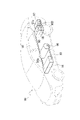
- FIG. 10 shows a vehicle VH on which unit 1 and fuel cell 95 are mounted. As shown in FIG. 10, the unit 1 is arranged behind the vehicle VH, and the fuel cell 95 is arranged in front of the vehicle VH. A hydrogen tank 96 is arranged under the vehicle interior VR in the center of the vehicle VH. A hydrogen tank 96 is connected to the fuel cell 95 via a pipe 99 .
- a water storage tank 97 is arranged behind the unit 1 of the vehicle VH.
- a drain port 97a is provided at the bottom of the water storage tank 97 .
- the fuel cell 95 and unit 1 are connected via a drainage pipe 98A.
- the unit 1 and the water storage tank 97 are connected via a drain pipe 98B. That is, the fuel cell 95 and the water storage tank 97 are connected via the drain pipe 98A, the unit 1 and the drain pipe 98B.
- the fuel cell 95 is also electrically connected to the unit 1 via wiring (not shown). In vehicle VH, electric power is supplied to motor 2 from drive battery 91 (see FIG. 8). Power is supplied from the fuel cell 95 when charging the drive battery 91 or when the power supplied from the drive battery 91 to the motor 2 is insufficient.
- hydrogen gas is supplied from a hydrogen tank 96 to the anode of a fuel cell 95, oxygen gas (air) taken in from the outside air is supplied to the cathode, and an electrochemical reaction is caused to generate electricity.
- Liquid Lq water: H 2 O
- the generated liquid Lq is introduced into the water storage tank 97 behind the vehicle VH through the drain pipes 98A and 98B, and is discharged from the water storage tank 97 through a drain port 97a to the outside of the vehicle.
- the exhaust gas (mainly nitrogen gas) generated by the electrochemical reaction may be introduced into the drain pipes 98A and 98B. Drainage pipes 98A and 98B are each connected to the unit 1 as described above. That is, the liquid Lq is introduced into the water storage tank 97 via the unit 1 . In the embodiment, the liquid Lq is used as a heat countermeasure for the unit 1 .
- a liquid Lq is interposed between the outer surface of the covering 90 and the outer surface of the housing HS.
- a retaining portion for retaining the liquid Lq is provided between the outer surface of the covering 90 and the outer surface of the housing HS. can be done.
- a channel for flowing the liquid Lq can be provided between the outer surface of the covering 90 and the outer surface of the housing HS.
- 'between the outer surface of the covering 90 and the outer surface of the housing HS' includes the concept of 'between the outer surface of the covering 90 and the inner surface of the covering 90'.
- a configuration for forming a flow path and the like are included.
- "between the outer surface of the covering 90 and the outer surface of the housing HS” includes the concept of "between the inner surface of the covering 90 and the outer surface of the housing HS".
- This concept includes, for example, configurations in which the clearance between the covering 90 and the housing HS is a stagnant part or flow path.
- This concept also includes a structure or the like that provides a retention portion (such as a box 93 into which the liquid Lq is introduced) or a flow path (such as a pipe through which the liquid Lq flows) between the covering 90 and the housing HS.
- a box 93 is provided between the inner surface of the covering 90 and the outer surface of the housing HS as a reservoir into which the liquid Lq is introduced.
- the box 93 is hatched for clarity.
- the box 93 is installed inside the covering 90 below the housing HS.
- the box 93 has a portion that overlaps the gear case 14 housing the power transmission mechanism 3 and the motor case 10 housing the motor 2 when viewed in the radial direction of the rotation axis X. As shown in FIG. 8, the box 93 is installed inside the covering 90 below the housing HS.
- the box 93 has a portion that overlaps the gear case 14 housing the power transmission mechanism 3 and the motor case 10 housing the motor 2 when viewed in the radial direction of the rotation axis X. As shown in FIG.
- An inlet 93a for the liquid Lq is provided on one end side (right side in the drawing) of the box 93 in the direction of the rotation axis X, and an outlet 93b is provided on the other end side (left side in the drawing).
- a drain pipe 98A extending from the fuel cell 95 penetrates the covering 90 and connects to the inlet 93a of the box 93.
- a drain pipe 98B extending from the water storage tank 97 passes through the covering 90 and connects to the outlet 93b of the box 93.
- the inlet 93 a and the outlet 93 b are provided apart from the bottom surface 93 d of the box 93 .
- the liquid Lq flowing through the drainage pipe 98A is introduced into the box 93 through the inlet 93a.
- the liquid Lq remaining in the box 93 reaches the height of the discharge port 93b, it is discharged to the drain pipe 98B through the discharge port 93b.
- the covering 90 includes a box 93 to function as a heat exchange section with the housing HS.
- the liquid Lq staying in the box 93 has a portion that overlaps the power transmission mechanism 3 when viewed from the radial direction of the rotation axis X.
- oil OL is stored in the lower part of the gear chamber Sb formed in the gear case 14 of the housing HS.
- the temperature of the oil OL stored in the gear chamber Sb tends to increase due to heat exchange with the meshing portions of the gears that constitute the power transmission mechanism 3 . Since the box 93 is positioned below the gear chamber Sb in the gravitational direction, heat is easily exchanged with the oil OL stored in the gear chamber Sb. This reduces the temperature rise of the oil OL stored in the gear chamber Sb, and contributes to heat countermeasures for the housing HS.
- the liquid Lq staying in the box 93 has a portion that overlaps the motor 2 when viewed from the radial direction of the rotation axis X.
- FIG. 8 shows an example in which the oil OL is stored in the gear chamber Sb.
- the oil OL can also be stored in the motor chamber Sa that accommodates the motor 2 .
- the temperature rise of the oil OL that is raked up by the motor 2 can be reduced by heat exchange with the liquid Lq staying in the box.
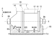
- FIG. 11 is a diagram showing the state of the box 93 viewed from above together with the housing HS.
- FIG. 12 is a diagram showing a cross section of the box 93 taken along line AA in FIG. 11 together with the housing HS.
- the upper outer surface 93c of the box 93 is hatched to make the region of the box 93 easier to understand.
- the box 93 has a substantially rectangular shape when viewed from above.
- the box 93 is formed in a size that allows the housing HS to be arranged inside the outer peripheral edge 930 of the box 93 .
- the box 93 has a rectangular parallelepiped shape with thickness in the vertical direction.
- the upper outer surface 93c of the box 93 is provided with a recess 931.
- the recess 931 opens upward in the vertical direction.
- the inner periphery of the recess 931 is formed to match the shape of the lower outer surface HSS of the housing HS.
- a lower outer surface HSS of the housing HS is positioned within the recess 931 . Inside the recess 931, the upper outer surface 93c and the lower outer surface HSS are in contact with each other. Thereby, the heat exchange efficiency between the liquid Lq in the box 93 and the housing HS can be improved.
- the illustrated box 93 is merely an example.
- the box 93 may have a rectangular parallelepiped shape without the concave portion 931, or may have a cylindrical shape. Also, a plurality of boxes 93 may be provided so as to surround the housing HS.
- the unit 1 and the water storage tank 97 are located on the rear side of the vehicle VH with respect to the fuel cell 95 that generates the liquid Lq. That is, the housing HS of the unit 1 and the drain port 97a of the water storage tank 97 are arranged close to each other. As a result, the drain pipe 98B connecting the housing HS of the unit 1 and the drain port 97a of the water storage tank 97 can be shortened. It is advantageous in terms of cost, weight and the like.
- the housing HS of the unit 1 and the water storage tank 97 are arranged behind the vehicle VH from the vehicle interior VR. This makes it difficult for the sound generated from the housing HS and the drain sound of the liquid Lq to reach the vehicle interior VR, which is advantageous for noise countermeasures.
- the drain port 97a of the water storage tank 97 is arranged behind the vehicle VH relative to the housing HS.
- the housing HS has a portion positioned between the drain port 97a of the water storage tank 97 and the vehicle interior VR.
- the housing HS functions as a wall that cuts off the exhaust sound, which is the noise generated from the water storage tank 97, which is advantageous for noise countermeasures.
- the unit 1 arranged below the vehicle VH reduces the temperature rise by exchanging heat with the running wind of the vehicle VH. Not susceptible to wind.
- a ventilation port VP is provided to communicate the inside of the vehicle interior VR with the space SP in which the housing HS is arranged.
- the air Air in the vehicle interior VR is discharged from the vent VP and flows into the space SP.
- the temperature of the air Air in the vehicle interior VR is adjusted according to the outside air temperature. For example, when the outside temperature is high, air conditioning is used in the vehicle VH, or the windows are opened. Also, for example, heating is used when the outside temperature is low.
- a fan or the like may be provided so that the air Air in the vehicle interior VR can easily flow into the space SP.
- the vehicle VH includes a housing HS that houses the power transmission mechanism 3; a covering 90 having a portion covering the housing HS; a liquid Lq interposed between the outer surface of the covering 90 and the outer surface of the housing HS.
- the liquid Lq can be effectively used.
- Noise is generated by the operation of the power transmission mechanism 3 housed in the housing HS.
- the housing HS By covering the housing HS that accommodates the power transmission mechanism 3 with the covering 90, it is possible to take measures against noise. However, since the housing HS is covered with the covering 90, heat tends to be trapped.
- the liquid Lq By interposing the liquid Lq between the outer surface of the covering 90 and the outer surface of the housing HS, the housing HS can be cooled by the liquid Lq.
- the liquid Lq also contributes to countermeasures against noise leaking to the outside of the housing HS. In this way, the liquid Lq can be effectively used as a countermeasure against heat or noise in the vehicle VH.
- Liquid Lq is waste water from the fuel cell 95 . Electric power generation in the fuel cell 95 produces liquid Lq (water). By interposing the liquid Lq discharged from the water storage tank 97 to the outside of the vehicle between the outer surface of the covering 90 and the outer surface of the housing HS, the drainage of the fuel cell 95 can be effectively utilized.
- the vehicle VH includes a housing HS that houses the power transmission mechanism 3, It has a covering 90 (heat exchanging portion) that exchanges heat between the housing HS and the liquid Lq, which is waste water from the fuel cell 95 .
- the drainage of the fuel cell 95 can be effectively used.
- Vehicle VH has drive battery 91 (electrical component) fixed to the outer surface of housing HS.
- the driving battery 91 has a portion that is offset from the covering 90 when viewed in the radial direction of the rotation axis X. As shown in FIG.
- the covering 90 and the outer surface of the housing HS can be brought closer.
- the heat exchange efficiency between the liquid Lq and the housing HS can be improved, contributing to heat countermeasures for the housing HS.
- the electrical components are also covered with the covering 90, the gap caused by the separation of the covering 90 from the surface of the housing HS is reduced, so that the noise countermeasure effect can be improved.
- the housing HS is located on the rear side of the vehicle VH with respect to the vehicle interior VR.
- the vehicle VH has a vent VP communicating with a space SP in which the housing HS is arranged in the vehicle interior VR.
- vent VP that communicates the inside of the vehicle interior VR with the space SP where the housing HS is arranged
- the air Air in the vehicle compartment VR whose temperature is adjusted according to the outside air temperature is introduced into the space SP, so that even on the rear side of the vehicle VH, which is less susceptible to the running wind, the temperature approaches the proper temperature of the housing HS. heat exchange can be performed.
- FIG. 13 is a schematic diagram showing a covering 90A according to Modification 1.
- FIG. 14 is a schematic diagram of the covering 90A according to Modification 1 as viewed from the rotation axis X direction.
- the covering 90A is provided with an opening 901 that exposes the outer surface of the housing HS.
- a nozzle 981 for injecting the liquid Lq is attached to the tip of the drain pipe 98A through which the liquid Lq discharged from the fuel cell 95 flows.
- the nozzle 981 may be one that jets the liquid Lq as a stream of water, or one that jets it in the form of a mist.
- the liquid Lq can be injected from the nozzle 981 by introducing the exhaust gas (mainly nitrogen gas) generated by the electrochemical reaction of the fuel cell 95 into the drain pipe 98A.
- the exhaust gas mainly nitrogen gas
- the nozzle 981 is arranged facing the outer surface of the housing HS exposed from the opening 901 formed in the covering 90A.
- the liquid Lq ejected from the nozzle 981 is sprayed onto the outer surface of the housing HS.
- the liquid Lq sprayed on the outer surface of the housing HS evaporates, it absorbs the heat of the outer surface of the housing HS, thereby contributing to heat countermeasures of the housing HS.
- a part of the liquid Lq sprayed on the outer surface of the housing HS is not vaporized, and runs downward in the direction of gravity along the outer surface of the housing HS according to gravity.
- a box 93 is provided in the lower portion of the housing HS as a reservoir for the liquid Lq.
- the box 93 of Modification 1 has an opening 93e in an upper outer surface 93c instead of the introduction port 93a (see FIG. 8).
- the liquid Lq that has run down the outer surface of the housing HS falls into the box 93 through the opening 93e and stays there.
- the liquid Lq staying in the box 93 contributes to heat countermeasures by exchanging heat with the housing HS as in the embodiment.
- the liquid Lq staying in the box 93 is introduced into the drain pipe 98B from the outlet 93b as in the embodiment.
- the opening 901 is provided in the covering 90A to expose the outer surface of the housing HS.
- a nozzle 981 is provided at the tip of the drain pipe 98A through which the liquid Lq discharged from the fuel cell 95 flows, and the nozzle 981 is arranged in the opening 901. FIG.
- the location where the opening 901 is provided is not limited, it can be, for example, an upper portion of the housing HS where heat is likely to be generated.
- the opening 901 in the upper portion of the housing HS can be cooled with a smaller flow rate of the liquid Lq than in the case where the stagnant portion of the liquid Lq is provided up to the upper portion of the housing HS.
- the opening 901 is provided in a region facing the motor case 10 in the covering 90A, the liquid Lq sprayed on the motor case 10 can contribute to heat countermeasures of the motor 2. Further, if the opening 901 is provided in a region of the covering 90 ⁇ /b>A facing the gear case 14 , for example, the liquid Lq sprayed onto the gear case 14 can contribute to countermeasures against heat in the power transmission mechanism 3 .
- Modification 1 combines the spraying of the liquid Lq from the opening 901 onto the outer surface of the housing HS with the box 93 capable of storing the liquid Lq running down the outer surface of the housing HS.
- the liquid Lq can be effectively used as a heat countermeasure for the housing HS.
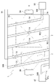
- FIG. 15 is a diagram showing a covering 90B according to Modification 2. As shown in FIG. As shown in FIG. 15, in Modification 2, the covering 90B is provided with a channel 902 through which the liquid Lq flows. Channels 902 can be provided, for example, between the outer and inner surfaces of the covering 90B.
- the flow path 902 can be configured by a tubular member provided integrally with the covering 90B.
- the tubular member preferably has such flexibility that the space inside the tube is not completely crushed even when it is bent along the outer periphery of the housing HS.
- the flow path 902 connects with the drain pipe 98A at one end (right side in the drawing) of the covering 90B in the direction of the rotation axis X, and connects with the drain pipe 98B at the other end (left side in the drawing).
- the flow path 902 is formed as one continuous flow path from the connecting portion with the drain pipe 98A to the connecting portion with the drain pipe 98B.
- the flow paths 902 extend along the circumferential direction around the rotation axis X and are provided out of phase in the rotation axis X direction. Therefore, the flow path 902 is arranged in a spiral shape surrounding the rotation axis X. As shown in FIG.
- heat is exchanged between the liquid Lq flowing through the flow path 902 and the housing HS.
- the helical flow path 902 can surround substantially the entire housing HS, so heat countermeasures can be taken with a small flow rate of the liquid Lq. . This contributes to reducing the amount of liquid Lq required for the entire vehicle VH.
- FIG. 15 illustrates the covering 90B as a rectangular parallelepiped shape, it is not limited to this.
- the covering 90B may be shaped along the outer surface of the housing HS so as to facilitate heat exchange between the flow path 902 and the housing HS. This increases the contact area of the covering 90 with the outer surface of the housing HS, thereby improving the heat exchange efficiency.
- the present invention is not limited to this.
- a heat exchanger oil cooler
- liquid Lq which is the waste water of the fuel cell 95
- oil oil
- the oil can be the oil OL used for lubricating and cooling the power transmission mechanism 3 or the motor 2 in the housing HS.
- liquid Lq which is waste water from the fuel cell 95
- an oil cooler separate from the oil cooler 83 may be provided.
- the channel may be a channel formed using part of the housing HS.
- a channel through which the liquid Lq flows may be formed between the outer surface and the inner surface of the housing HS.
- a pipe may be provided in the covering 90 to contact the oil reservoir in the housing HS.
- a pipe through which the liquid Lq, which is the waste water of the fuel cell 95, flows may be arranged so as to pass through the oil stored in the lower part of the gear chamber Sb of the housing HS.
- the inverter 7 may be provided next to the housing HS, and a flow path through which the liquid Lq flows may be provided between the housing HS and the inverter 7 as a heat exchange section. This contributes to countermeasures against heat generated in the inverter 7 .
- a driving battery 91 may be provided next to the housing HS, and a flow path through which the liquid Lq flows may be provided between the housing HS and the driving battery 91 as a heat exchange portion. This contributes to countermeasures against heat generated in the driving battery 91 .
- a flow path or a heat exchanger may be provided as a heat exchange part between the housing HS and the cover ring 90 or in the dead space inside the housing HS.
- an example of heat exchange between the housing HS and the liquid Lq was described as a heat countermeasure for the housing HS, but the present invention is not limited to this.
- a countermeasure against heat for example, it is conceivable to reduce the amount of heat exchanged between the housing HS and other parts.
- the amount of heat exchange between the housing HS and elements outside the housing HS can be reduced.
- the amount of heat exchanged between the housing HS and an external heat source having a higher temperature than the housing HS can be reduced.
- measures such as reducing the amount of heat exchanged between the housing HS and an external component that requires a lower temperature than the unit 1 having the housing HS can be considered.
- the housing HS that accommodates at least the power transmission mechanism 3 is taken as an example.
- a housing HS that accommodates at least the motor 2 may be used.
- the power transmission mechanism 3 may or may not be housed in the same housing HS.
- a housing HS that accommodates at least the inverter 7 may be used.
- the power transmission mechanism 3 may or may not be accommodated within the same housing HS.
- the housing HS may contain at least a battery.
- the battery can be, for example, a drive battery 91 (see FIG. 8).
- the power transmission mechanism 3 may or may not be accommodated within the same housing HS.
- the power transmission mechanism 3 has, for example, a gear mechanism, an annular mechanism, or the like.
- the gear mechanism includes, for example, a reduction gear mechanism, an increase gear mechanism, a differential gear mechanism (differential mechanism), and the like.
- the reduction gear mechanism and the acceleration gear mechanism have, for example, a planetary gear mechanism, a parallel gear mechanism, and the like.
- the annular mechanism has, for example, an endless annular component or the like. Endless annular parts and the like include, for example, chain sprockets, belts and pulleys, and the like.
- the differential mechanism 5 is, for example, a bevel gear type differential gear, a planetary gear type differential gear, or the like.
- the differential mechanism 5 has a differential case that is an input element, two output shafts that are output elements, and a differential gear set that is a differential element.
- the differential gear set In a bevel gear type differential gear, the differential gear set has bevel gears.
- the differential gear set In a planetary gear type differential gear, the differential gear set has planetary gears.
- the unit 1 has a gear that rotates integrally with the differential case.
- a final gear (differential ring gear) of the parallel gear mechanism rotates integrally with the differential case.
- the pinion gear rotates (revolves) integrally with the differential case.
- a reduction gear mechanism is connected downstream of the motor 2 .
- a differential gear mechanism is connected downstream of the reduction gear mechanism. That is, a differential gear mechanism is connected downstream of the motor 2 via a reduction gear mechanism.
- a speed increasing gear mechanism may be used instead of the speed reducing gear mechanism.
- a single-pinion planetary gear mechanism can use, for example, a sun gear as an input element, a ring gear as a fixed element, and a carrier as an output element.
- a double-pinion planetary gear mechanism can have, for example, a sun gear as an input element, a ring gear as an output element, and a carrier as a fixed element.
- a stepped pinion gear, a non-stepped pinion gear, or the like can be used as the pinion gear of the single pinion type or double pinion type planetary gear mechanism.
- a stepped pinion gear has a large pinion and a small pinion. For example, it is preferable to mesh the large pinion with the sun gear. For example, it is preferable to fit the small pinion to the ring gear.
- a non-stepped pinion gear is a type that is not a stepped pinion gear.
- the unit 1 is mounted on a vehicle, but it is not limited to this aspect, and the unit 1 can be applied to other than vehicles. Moreover, when a plurality of examples and modifications are described in this embodiment, these may be combined arbitrarily.
- Unit 3 Power transmission mechanism 90: Covering (heat exchange part) 91: Driving battery (electrical parts) 92: Vent 93: Box 95: Fuel cell VH: Vehicle VR: Vehicle interior HS: Housing Lq: Liquid
Landscapes
- Engineering & Computer Science (AREA)
- Power Engineering (AREA)
- Mechanical Engineering (AREA)
- Chemical & Material Sciences (AREA)
- Combustion & Propulsion (AREA)
- Transportation (AREA)
- General Engineering & Computer Science (AREA)
- General Details Of Gearings (AREA)
- Arrangement Or Mounting Of Propulsion Units For Vehicles (AREA)
- Fuel Cell (AREA)
- Cooling, Air Intake And Gas Exhaust, And Fuel Tank Arrangements In Propulsion Units (AREA)
Priority Applications (4)
| Application Number | Priority Date | Filing Date | Title |
|---|---|---|---|
| JP2023529733A JP7547023B2 (ja) | 2021-06-24 | 2022-05-26 | 車両 |
| EP22828134.1A EP4360928A4 (en) | 2021-06-24 | 2022-05-26 | VEHICLE |
| US18/562,006 US20240239183A1 (en) | 2021-06-24 | 2022-05-26 | Vehicle |
| CN202280044587.9A CN117580724A (zh) | 2021-06-24 | 2022-05-26 | 车辆 |
Applications Claiming Priority (2)
| Application Number | Priority Date | Filing Date | Title |
|---|---|---|---|
| JP2021105245 | 2021-06-24 | ||
| JP2021-105245 | 2021-06-24 |
Publications (1)
| Publication Number | Publication Date |
|---|---|
| WO2022270215A1 true WO2022270215A1 (ja) | 2022-12-29 |
Family
ID=84543826
Family Applications (1)
| Application Number | Title | Priority Date | Filing Date |
|---|---|---|---|
| PCT/JP2022/021497 Ceased WO2022270215A1 (ja) | 2021-06-24 | 2022-05-26 | 車両 |
Country Status (5)
| Country | Link |
|---|---|
| US (1) | US20240239183A1 (https=) |
| EP (1) | EP4360928A4 (https=) |
| JP (1) | JP7547023B2 (https=) |
| CN (1) | CN117580724A (https=) |
| WO (1) | WO2022270215A1 (https=) |
Families Citing this family (1)
| Publication number | Priority date | Publication date | Assignee | Title |
|---|---|---|---|---|
| WO2022270214A1 (ja) * | 2021-06-24 | 2022-12-29 | ジヤトコ株式会社 | ユニット |
Citations (10)
| Publication number | Priority date | Publication date | Assignee | Title |
|---|---|---|---|---|
| JP2003017099A (ja) | 2001-07-04 | 2003-01-17 | Equos Research Co Ltd | 燃料電池装置 |
| JP2008267465A (ja) | 2007-04-18 | 2008-11-06 | Toyota Motor Corp | 車両用駆動装置 |
| JP2010212126A (ja) | 2009-03-11 | 2010-09-24 | Toyota Motor Corp | 燃料電池システム |
| JP2015209043A (ja) | 2014-04-24 | 2015-11-24 | 本田技研工業株式会社 | 車両の排気構造 |
| JP2016117366A (ja) * | 2014-12-19 | 2016-06-30 | トヨタ自動車株式会社 | 電池パックの冷却装置 |
| JP2016134322A (ja) * | 2015-01-21 | 2016-07-25 | トヨタ自動車株式会社 | 電池パックの冷却装置 |
| JP2018050385A (ja) | 2016-09-21 | 2018-03-29 | いすゞ自動車株式会社 | 電気自動車 |
| JP2019046720A (ja) * | 2017-09-05 | 2019-03-22 | トヨタ自動車株式会社 | 燃料電池システム |
| JP2019051872A (ja) * | 2017-09-15 | 2019-04-04 | トヨタ自動車株式会社 | 車両の熱交換システム |
| CN210652704U (zh) * | 2019-07-05 | 2020-06-02 | 北京新能源汽车技术创新中心有限公司 | 车载氢气燃烧装置及氢燃料电池车 |
Family Cites Families (17)
| Publication number | Priority date | Publication date | Assignee | Title |
|---|---|---|---|---|
| US4125345A (en) * | 1974-09-20 | 1978-11-14 | Hitachi, Ltd. | Turbo-fluid device |
| JPS6022520A (ja) * | 1983-07-13 | 1985-02-05 | Nippon Denso Co Ltd | 車両用換気機構 |
| JP3794392B2 (ja) * | 2003-02-25 | 2006-07-05 | 日産自動車株式会社 | 電気自動車の駆動ユニット |
| US7445064B2 (en) * | 2003-04-07 | 2008-11-04 | Jay Eung Jung Kim | Vehicle using wind force |
| JP2004335177A (ja) * | 2003-05-01 | 2004-11-25 | Sumitomo Electric Ind Ltd | 燃料電池搭載車 |
| JP2008125181A (ja) * | 2006-11-09 | 2008-05-29 | Advics:Kk | 燃料電池車 |
| JP6200790B2 (ja) * | 2013-12-02 | 2017-09-20 | 本田技研工業株式会社 | 車両用駆動装置 |
| WO2015177332A1 (de) * | 2014-05-23 | 2015-11-26 | Voith Patent Gmbh | Stirnradgetriebe |
| CN108233604A (zh) * | 2016-12-15 | 2018-06-29 | 佛山市净瓶泉卫浴有限公司 | 一种驱动设备 |
| JP6518718B2 (ja) * | 2017-05-09 | 2019-05-22 | 本田技研工業株式会社 | 動力装置 |
| JP2019030131A (ja) * | 2017-07-31 | 2019-02-21 | 株式会社豊田自動織機 | 無人搬送車 |
| WO2019194077A1 (ja) * | 2018-04-06 | 2019-10-10 | 日本電産株式会社 | モータユニット |
| EP3783778A4 (en) * | 2018-06-08 | 2021-06-02 | Aisin Aw Co., Ltd. | DYNAMO-ELECTRIC MACHINE, AND VEHICLE DRIVE DEVICE INCLUDING A DYNAMO-ELECTRIC MACHINE |
| DE102019207787A1 (de) * | 2019-05-28 | 2020-12-03 | Zf Friedrichshafen Ag | Elektrischer Antrieb für ein Fahrzeug in einem Gehäuse |
| JP6990217B2 (ja) * | 2019-07-02 | 2022-01-12 | 本田技研工業株式会社 | 車両 |
| CN110729856A (zh) * | 2019-09-03 | 2020-01-24 | 精进电动科技股份有限公司 | 一种油水双冷的电驱动总成和新能源汽车 |
| JP6770662B1 (ja) * | 2020-05-07 | 2020-10-14 | 柴山 尚士 | 燃料電池車 |
-
2022
- 2022-05-26 CN CN202280044587.9A patent/CN117580724A/zh active Pending
- 2022-05-26 EP EP22828134.1A patent/EP4360928A4/en active Pending
- 2022-05-26 WO PCT/JP2022/021497 patent/WO2022270215A1/ja not_active Ceased
- 2022-05-26 JP JP2023529733A patent/JP7547023B2/ja active Active
- 2022-05-26 US US18/562,006 patent/US20240239183A1/en active Pending
Patent Citations (10)
| Publication number | Priority date | Publication date | Assignee | Title |
|---|---|---|---|---|
| JP2003017099A (ja) | 2001-07-04 | 2003-01-17 | Equos Research Co Ltd | 燃料電池装置 |
| JP2008267465A (ja) | 2007-04-18 | 2008-11-06 | Toyota Motor Corp | 車両用駆動装置 |
| JP2010212126A (ja) | 2009-03-11 | 2010-09-24 | Toyota Motor Corp | 燃料電池システム |
| JP2015209043A (ja) | 2014-04-24 | 2015-11-24 | 本田技研工業株式会社 | 車両の排気構造 |
| JP2016117366A (ja) * | 2014-12-19 | 2016-06-30 | トヨタ自動車株式会社 | 電池パックの冷却装置 |
| JP2016134322A (ja) * | 2015-01-21 | 2016-07-25 | トヨタ自動車株式会社 | 電池パックの冷却装置 |
| JP2018050385A (ja) | 2016-09-21 | 2018-03-29 | いすゞ自動車株式会社 | 電気自動車 |
| JP2019046720A (ja) * | 2017-09-05 | 2019-03-22 | トヨタ自動車株式会社 | 燃料電池システム |
| JP2019051872A (ja) * | 2017-09-15 | 2019-04-04 | トヨタ自動車株式会社 | 車両の熱交換システム |
| CN210652704U (zh) * | 2019-07-05 | 2020-06-02 | 北京新能源汽车技术创新中心有限公司 | 车载氢气燃烧装置及氢燃料电池车 |
Non-Patent Citations (1)
| Title |
|---|
| See also references of EP4360928A4 |
Also Published As
| Publication number | Publication date |
|---|---|
| US20240239183A1 (en) | 2024-07-18 |
| JP7547023B2 (ja) | 2024-09-09 |
| CN117580724A (zh) | 2024-02-20 |
| EP4360928A1 (en) | 2024-05-01 |
| EP4360928A4 (en) | 2024-10-30 |
| JPWO2022270215A1 (https=) | 2022-12-29 |
Similar Documents
| Publication | Publication Date | Title |
|---|---|---|
| JP7486912B2 (ja) | ユニット | |
| JP7527751B2 (ja) | ユニット | |
| JP7399602B2 (ja) | ユニット | |
| JP7418940B2 (ja) | ユニット | |
| JP7451069B2 (ja) | ユニット | |
| JP7399603B2 (ja) | ユニット | |
| CN117561388A (zh) | 组件 | |
| JP7456382B2 (ja) | モータユニット | |
| CN117561390A (zh) | 组件 | |
| JP7547023B2 (ja) | 車両 | |
| CN115053088A (zh) | 动力传递装置及车辆 | |
| JP7321950B2 (ja) | 動力伝達装置 | |
| WO2022270101A1 (ja) | ユニット | |
| WO2022270102A1 (ja) | ユニット |
Legal Events
| Date | Code | Title | Description |
|---|---|---|---|
| 121 | Ep: the epo has been informed by wipo that ep was designated in this application |
Ref document number: 22828134 Country of ref document: EP Kind code of ref document: A1 |
|
| WWE | Wipo information: entry into national phase |
Ref document number: 2023529733 Country of ref document: JP |
|
| WWE | Wipo information: entry into national phase |
Ref document number: 18562006 Country of ref document: US |
|
| WWE | Wipo information: entry into national phase |
Ref document number: 202280044587.9 Country of ref document: CN |
|
| WWE | Wipo information: entry into national phase |
Ref document number: 2022828134 Country of ref document: EP |
|
| NENP | Non-entry into the national phase |
Ref country code: DE |
|
| ENP | Entry into the national phase |
Ref document number: 2022828134 Country of ref document: EP Effective date: 20240124 |