WO2022264891A1 - スパークプラグ - Google Patents
スパークプラグ Download PDFInfo
- Publication number
- WO2022264891A1 WO2022264891A1 PCT/JP2022/023077 JP2022023077W WO2022264891A1 WO 2022264891 A1 WO2022264891 A1 WO 2022264891A1 JP 2022023077 W JP2022023077 W JP 2022023077W WO 2022264891 A1 WO2022264891 A1 WO 2022264891A1
- Authority
- WO
- WIPO (PCT)
- Prior art keywords
- opening
- spark plug
- peripheral surface
- screw
- thread
- Prior art date
- Legal status (The legal status is an assumption and is not a legal conclusion. Google has not performed a legal analysis and makes no representation as to the accuracy of the status listed.)
- Ceased
Links
Images


Classifications
-
- H—ELECTRICITY
- H01—ELECTRIC ELEMENTS
- H01T—SPARK GAPS; OVERVOLTAGE ARRESTERS USING SPARK GAPS; SPARKING PLUGS; CORONA DEVICES; GENERATING IONS TO BE INTRODUCED INTO NON-ENCLOSED GASES
- H01T13/00—Sparking plugs
- H01T13/02—Details
- H01T13/08—Mounting, fixing or sealing of sparking plugs, e.g. in combustion chamber
-
- H—ELECTRICITY
- H01—ELECTRIC ELEMENTS
- H01T—SPARK GAPS; OVERVOLTAGE ARRESTERS USING SPARK GAPS; SPARKING PLUGS; CORONA DEVICES; GENERATING IONS TO BE INTRODUCED INTO NON-ENCLOSED GASES
- H01T13/00—Sparking plugs
- H01T13/20—Sparking plugs characterised by features of the electrodes or insulation
- H01T13/32—Sparking plugs characterised by features of the electrodes or insulation characterised by features of the earthed electrode
-
- H—ELECTRICITY
- H01—ELECTRIC ELEMENTS
- H01T—SPARK GAPS; OVERVOLTAGE ARRESTERS USING SPARK GAPS; SPARKING PLUGS; CORONA DEVICES; GENERATING IONS TO BE INTRODUCED INTO NON-ENCLOSED GASES
- H01T13/00—Sparking plugs
- H01T13/20—Sparking plugs characterised by features of the electrodes or insulation
- H01T13/39—Selection of materials for electrodes
Definitions
- the present disclosure relates to spark plugs used in internal combustion engines.
- Spark plugs are used as ignition means for internal combustion engines such as automobile engines.
- a spark plug is provided with a center electrode and a ground electrode as a structure for generating spark discharge.
- the center electrode is attached to the inside of a tubular metallic shell that extends along the axis and extends along the axis.
- a ground electrode is positioned adjacent to the tip of the center electrode.
- spark plugs are attached to the metal shell by forming an opening in the cylindrical metal shell and inserting a rod-shaped ground electrode into the opening (for example, Patent Document 1). reference).
- a hole 34c passing through the mounting threaded portion 52c in a direction perpendicular to the axis AX of the spark plug is formed at the tip portion of the mounting threaded portion 52c of the metallic shell 50c. formed.
- a ground electrode tip 39c is press-fitted into the hole 34c.
- the hole (opening) provided in the mounting screw portion of the metal shell is formed by cutting the outer peripheral surface of the metal shell. Normally, the shape of the cut surface of the opening provided in the metal shell is perpendicular to the central axis of the inner diameter of the metal shell, as in the spark plug of Patent Document 1, for example.
- the cut surface of the opening is perpendicular to the center axis of the inner diameter of the metal shell, when the spark plug is screwed into the screw hole of the internal combustion engine, the screw located at the boundary between the opening and the opening may be damaged.
- the crest is inclined forward with respect to the direction of rotation of the screw. Therefore, when the spark plug is connected to the internal combustion engine, the thread of the spark plug may get caught in the screw hole of the internal combustion engine.
- a spark plug includes a metal member having a cylindrical portion extending along an axis, a center electrode disposed in the cylindrical portion and extending along the axis, and a center electrode provided in the cylindrical portion. and a ground electrode that is inserted into the opening in the center electrode and forms a gap between the distal end portion in the extending direction of the electrode and the center electrode.
- a screw thread is provided on the outer peripheral surface of the tubular portion, and a cross section of the tubular portion in a direction orthogonal to the axis line shows a cross section between the apex of the screw thread and the opening.
- the opening In the cross section at the position where the edge intersects, the opening has an inclined portion that tapers from the outer peripheral surface toward the inner peripheral surface of the cylindrical portion, and the apex of the thread and the The angle between the tangent line of the outer peripheral surface at the boundary position with the opening and the inclined portion at the opening is 90 degrees or more.
- the screw thread provided on the outer peripheral surface of the cylindrical portion has a shape that does not incline forward with respect to the advancing direction of the screw. Therefore, it is possible to reduce the possibility that the screw thread gets caught in the screw hole of the internal combustion engine when the spark plug is fastened to or removed from the internal combustion engine.
- the inclined portion may be provided from at least the apex of the thread to the groove of the thread.
- the cut surface of the opening is inclined over the entire thread (that is, from the top of the thread to the bottom of the thread groove), so that when the spark plug is attached to or removed from the internal combustion engine, the cutting surface is inclined.
- the inclined portions are provided on both sides of the opening in a cross section of the opening at a position where the apex of the thread and the edge of the opening intersect.
- the inclined portion of the opening exists in the direction in which the screw advances, regardless of whether the spark plug rotates clockwise or counterclockwise with the axis as the starting point. Therefore, it is possible to prevent the threads from being caught both when the spark plug is attached to and removed from the internal combustion engine.
- the inclined portion may be provided in a region extending over two or more of the screw threads.
- the diameter of the opening is set according to the size of the ground electrode, and the thread width of the thread provided on the outer peripheral surface of the cylindrical portion (the size between two threads adjacent in the axial direction). is larger than Therefore, the opening is formed over two or more axially adjacent thread forming regions. Therefore, it is preferable that the inclined portion provided in the opening is also formed over two or more axially adjacent thread forming regions. As a result, it is possible to prevent the threads existing at the edge of the opening from being bitten.
- the spark plug according to one aspect of the present disclosure, it is possible to suppress biting of the screw threads formed on the outer peripheral surface of the metal fitting member when the spark plug is attached to the internal combustion engine.
- FIG. 1 is a partial cross-sectional view showing the appearance and internal configuration of a spark plug according to one embodiment
- FIG. FIG. 2 is a schematic side view showing an enlarged mounting portion of the center electrode and the ground electrode in the spark plug according to the first embodiment
- 1 is a side view showing the appearance of a spark plug according to a first embodiment
- FIG. 1 is a perspective view showing the appearance of a spark plug according to a first embodiment
- FIG. 4 is a cross-sectional view showing the configuration of the AA line portion of the metallic shell shown in FIG. 3
- FIG. FIG. 3 is a schematic diagram showing the cross-sectional shape of an opening formed in the metallic shell of the spark plug according to the first embodiment
- FIG. 3 is a schematic diagram showing a cross-sectional shape of an opening formed in a metal shell of a conventional spark plug.
- FIG. 4 is a schematic diagram showing the cross-sectional shape of the opening formed in the metallic shell of the spark plug for comparison.
- FIG. 10 is an enlarged side view showing attachment portions of a center electrode and a ground electrode in a spark plug according to a second embodiment;
- FIG. 3 is a cross-sectional view showing the configuration of a metal shell provided in a conventional spark plug;
- FIG. 1 shows a schematic configuration of a spark plug 1 according to one embodiment of the invention.
- the spark plug 1 includes an insulator 50 and a metal shell (metal fitting member) 30 .
- the insulator 50 is a substantially cylindrical member extending in the longitudinal direction of the spark plug 1 .
- a shaft hole extending along the axis O is formed in the insulator 50 .
- the insulator 50 is made of a material with excellent insulation, heat resistance, and thermal conductivity.
- the insulator 50 is made of alumina-based ceramic or the like.
- a center electrode 21 is provided at a tip portion 51 of the insulator 50 .
- the side on which the center electrode 21 is provided is the front end side of the spark plug 1, and the other end side is the rear end side.
- a terminal fitting 52 is attached to the rear end of the insulator 50 .
- the center electrode 21 is held through the shaft hole of the insulator 50 with its tip protruding from the tip 51 of the insulator 50 .
- the center electrode 21 is attached to the insulator 50 so as to be positioned on the axis O of the substantially cylindrical insulator 50 .
- the center electrode 21 has a substantially cylindrical shape, and its diameter is slightly reduced toward its tip.
- a cylindrical noble metal tip (not shown), for example, is joined to the tip of the center electrode 21 by welding or the like.
- the center electrode 21 is made of, for example, a metal material such as a Ni-based alloy containing Ni (nickel) as a main component. Al (aluminum) etc. are mentioned as an alloying element added to a Ni-based alloy.
- a core material (not shown) may be embedded inside the center electrode 21 .
- the core material can be made of a metal material (for example, Cu (copper) or a Cu alloy) having a higher thermal conductivity than the electrode base material forming the center electrode 21 . Note that in another embodiment, the core material may not be provided inside the center electrode 21 . That is, the center electrode may be formed only of the electrode base material.
- the metal shell 30 is a substantially cylindrical member fixed to a screw hole of the internal combustion engine.
- the metal shell 30 is provided so as to partially cover the outer periphery of the insulator 50 .
- the gap between the metal shell 30 and the insulator 50 on the rear end side is filled with talc 61 .
- the metal shell 30 is made of a conductive metal material. Examples of such metal materials include low-carbon steel, metal materials containing iron as a main component, and the like.
- the metal shell 30 mainly includes a crimping portion 31, a tool engaging portion 32, a curved portion 33, a seat portion 34, a body portion 36, and the like. These parts are arranged along the axis O and form a cylindrical portion 30a of the metallic shell 30 as a whole.
- the crimping part 31 and the curved part 33 are parts for attaching the metal shell 30 to the insulator 50 .
- the tool engaging portion 32 is a portion with which a tool such as a wrench is engaged when attaching the metal shell 30 to a screw hole of the internal combustion engine.
- the seat portion 34 is positioned between the tool engaging portion 32 and the body portion 36 .
- An annular gasket is arranged on the seat portion 34 when the spark plug 1 is attached to the internal combustion engine.
- the trunk portion 36 is located on the tip portion 51 side of the insulator 50 .
- a ground electrode 11 is provided on the tip side of the metal shell 30 (the side on which the trunk portion 36 is located).
- the ground electrode 11 is a rod-shaped member that penetrates the substantially cylindrical body portion 36 and extends toward the center electrode 21 in a direction substantially perpendicular to the axis O. As shown in FIG.
- the ground electrode 11 is inserted into the cylindrical portion 30a through an opening 40 provided in the body portion 36. As shown in FIG.
- the ground electrode 11 is formed using, for example, a metal material such as a Ni-based alloy containing Ni (nickel) as a main component as an electrode base material.
- a metal material such as a Ni-based alloy containing Ni (nickel) as a main component as an electrode base material.
- Al (aluminum) etc. are mentioned as an alloying element added to a Ni-based alloy.
- the ground electrode 11 may contain at least one element selected from Mn (manganese), Cr (chromium), Al (aluminum), and Ti (titanium) as a component other than Ni.
- metal materials containing noble metals such as Pt (platinum) and Ir (iridium) as main components may also be used.
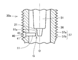
- FIG. 2 shows a state in which the ground electrode 11 is attached to the opening 40 of the metallic shell 30.
- FIG. 2 the spark plug 1 according to the present embodiment is a so-called lateral discharge type spark plug in which the tip surface 11a of the ground electrode 11 is arranged to face the side surface of the center electrode 21. As shown in FIG.
- a discharge gap G is formed (see FIG. 2).
- the base material of the ground electrode 11 has a front end surface 11a facing the side surface of the center electrode 21.
- the front end surface of the base material of the ground electrode 11 may be A configuration including a noble metal tip may be employed.
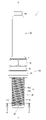
- FIG. 3 is a side view of the spark plug 1 on the side where the opening 40 is provided.
- 4 is a perspective view of the spark plug 1 showing the shape of the opening 40.
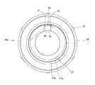
- FIG. 5 shows the configuration of the cross section of the metallic shell 30 .
- FIG. 5 is a cross-sectional view taken along line AA shown in FIG. This AA line is a line orthogonal to the axis O and passes through a position where one vertex of the screw thread 37a and the edge of the opening 40 intersect.
- the opening 40 is provided on the tip side of the body 36 of the metal shell 30 . More specifically, the opening 40 is formed at substantially the same position in the direction of the axis O as the tip of the center electrode 21 provided at the tip of the insulator 50 . Accordingly, when the ground electrode 11 is attached to the opening 40 , the tip surface 11 a of the ground electrode 11 is arranged to face the side surface of the center electrode 21 near the tip.
- the opening 40 has a size that allows insertion of a rod-shaped electrode base material forming the ground electrode 11 .
- the diameter of the opening 40 is set to be larger than the thread width of the thread shape 37 provided on the surface of the body 36 (the size between two axially adjacent thread ridges 37a, 37a). It is Therefore, the opening 40 is formed over areas where two or more axially adjacent screw threads 37a are formed.
- a tapered portion 41 is inclined so as to taper from the outer peripheral surface toward the inner peripheral surface of the cylindrical portion 30a (that is, to narrow the opening diameter of the opening 40). is provided.
- Such a tapered portion 41 is formed at least on the outer peripheral surface side of the cylindrical portion 30a into which the electrode base material of the ground electrode 11 is inserted. Since the opening portion 40 on the outer peripheral surface side of the cylindrical portion 30a has such a shape, when the spark plug 1 is screwed into the screw hole of the internal combustion engine, the screw thread 37a is aligned with the screw of the internal combustion engine. The possibility of getting caught in holes can be reduced.
- FIG. 5 is a cross-sectional view of the trunk portion 36 of the metal shell 30 cut at a position orthogonal to the axis O and at the intersection of one vertex of the screw thread 37a and the edge of the opening 40.
- the tapered portion 41 is provided at least in the area where the screw shape 37 is formed.
- the tapered portion 41 is provided slightly from the area where the threaded shape 37 is formed to the inner peripheral surface side. That is, the tapered portion 41 is provided to a position slightly deeper than the depth of the groove of the screw shape 37 .
- the inner cut surface 42 of the opening 40 on the inner peripheral surface side of the formation area of the screw shape 37 is not tapered, and the opening diameter of the opening 40 is constant. It's becoming The opening diameter of the opening 40 in the area where the far side cut surface 42 is formed is set according to the dimensions of the electrode base material of the ground electrode 11 to be inserted.
- FIG. 10 shows a cross-sectional configuration of a metal shell 930 of a conventional spark plug.
- This figure is a cross-sectional view of a metal shell 930 of a conventional spark plug cut at a position corresponding to line AA shown in FIG.
- the cylindrical portion 30a (specifically, the trunk portion 36) of the metal shell 930 is provided with an opening 940 into which the ground electrode 11 is inserted.
- the metal shell 930 has the same basic configuration as that of the metal shell 30 except for the opening 940 .
- the opening diameter of the opening 940 is substantially constant from the outer peripheral surface to the inner peripheral surface of the cylindrical portion 30a. That is, the taper portion 41 is not provided in the opening 940 formed in the metallic shell 930 of the conventional spark plug, and the cut surface 942 of the opening 940 is perpendicular to the central axis of the inner diameter of the metallic shell 930. It has a nice shape. If the opening 940 has such a shape, when the spark plug is screwed into the threaded hole of the internal combustion engine, the screw thread located at the boundary with the opening 940 is aligned in the rotational direction of the screw (that is, It becomes a shape inclined forward with respect to the traveling direction of the spark plug (see FIG. 7). As a result, there is a possibility that the screw thread will get caught in the screw hole of the internal combustion engine when the spark plug is connected to or removed from the internal combustion engine.
- the taper portion 41 is provided in the opening portion 40 provided in the metallic shell 30 .
- Such a tapered portion 41 is preferably provided at least in the formation region of the screw shape 37 (that is, from the screw thread 37a to the screw groove 37b) in the depth direction of the opening 40.
- the tapered shape is formed over the entire region where the threaded shape 37 is formed on the outer peripheral surface side of the body portion 36, so that when the spark plug 1 is attached to or removed from the internal combustion engine, the rim portion of the opening portion is difficult to reach. Biting can be suppressed more reliably.
- the tapered portions 41 are provided on both sides of the opening 40 in the cross section of the opening 40 at the position where the apex of the thread 37a and the edge of the opening 40 intersect. preferable. As a result, it is possible to prevent the screw from getting caught both when the spark plug 1 is attached to and detached from the internal combustion engine (that is, in both advancing directions R1 and R2 of the screw shown in FIG. 6).
- the tapered portion 41 as described above is provided over substantially the entire area of the edge of the opening 40 . This facilitates processing of the cut surface having the tapered portion 41 when forming the opening portion 40 by counterbore processing using a cutting tool.
- FIG. 6 to 8 schematically show cross sections of metal shells 30 having openings with different cross-sectional shapes.
- R1 indicates the direction in which the screw advances when connecting the spark plug 1 to the internal combustion engine
- R2 indicates the direction in which the screw advances when removing the spark plug 1 from the internal combustion engine.
- FIG. 6 is a schematic diagram showing the shape of the cross section of the opening 40 of the spark plug 1 according to this embodiment (for example, the cross section taken along line AA in FIG. 3).
- FIG. 6 shows only the shape of the opening 40 on the outer peripheral surface side. That is, in FIG. 6, illustration of the back side cutting surface 42 provided on the inner peripheral surface side of the tapered portion 41 is omitted.
- the tangent T to the outer peripheral surface at the boundary position between the apex of the thread 37a provided on the outer peripheral surface of the cylindrical portion 30a of the metal shell 30 and the opening 40 and the opening 40 is 90 degrees or more.
- FIG. 7 is a schematic diagram showing the shape of the cross section of the opening 940 of the metal shell 930 of the conventional spark plug (for example, the cross section at the position corresponding to the line AA in FIG. 3).
- the cut surface 942 of the opening 940 of the metal shell 930 has a shape perpendicular to the central axis of the inner diameter of the metal shell 930 .
- the tangent T to the outer peripheral surface at the boundary position between the apex of the screw thread 37a provided on the outer peripheral surface of the cylindrical portion 30a of the metal shell 930 and the opening 940 and the opening 940 is an acute angle (less than 90 degrees).
- the screw thread located at the boundary with the opening 940 has a shape that is inclined forward with respect to the direction of rotation of the screw (that is, the advancing direction R1 or R2 of the spark plug).
- the screw thread will get caught in the screw hole of the internal combustion engine when the spark plug is connected to or removed from the internal combustion engine.
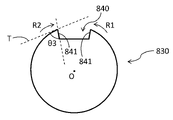
- FIG. 8 is a schematic diagram showing the shape of the cross section of the opening 840 of the metal shell 830 of the spark plug to be compared (for example, the cross section at the position corresponding to the line AA in FIG. 3).
- An opening 840 shown in FIG. 8 is provided with a tapered portion 841 that tapers from the outer peripheral surface toward the inner peripheral surface of the cylindrical portion 30a.
- the tapered portion 841 has an inclination angle with respect to the tangent line T different from that of the tapered portion 41 .
- the screw thread located at the boundary with the opening 840 has a shape slightly forward with respect to the direction of rotation of the screw (that is, the traveling direction R1 or R2 of the spark plug).
- the possibility of the thread being caught during screw rotation is reduced, but when the spark plug is attached to or detached from the internal combustion engine, the thread may become a thread of the internal combustion engine. It can get stuck in holes.
- the angle ⁇ 1 formed by the tangent line T to the outer peripheral surface of the metal shell 30 and the tapered portion 41 of the opening 40 is 90 degrees or more.
- the opening 40 is provided with the tapered portion 41 as described above, when the ground electrode 11 is attached to the opening 40 of the metallic shell 30, the electrode base material and the screw thread to be inserted into the opening 40 can be adjusted. 37a can be reduced. Therefore, the process of inserting and fixing the ground electrode during manufacture of the spark plug 1 can be performed more easily.
- the opening 40 in the metal shell 30 when forming the opening 40 in the metal shell 30, conventionally known cutting, counterbore processing, or the like can be used. Then, a rod-shaped electrode base material to be the ground electrode 11 is inserted into the formed opening 40 and fixed. Fixing of the ground electrode 11 to the metal shell 30 is performed by press fitting or welding, for example. As a result, the ground electrode 11 extending from the cylindrical portion 30a of the metal shell 30 in the direction intersecting with the axis O is obtained.
- the same manufacturing method as the conventional method of manufacturing a spark plug can be applied to the manufacturing steps other than the step of forming the opening 40. As shown in FIG.
- the cross-sectional shape of the opening 40 obtained by cutting the trunk portion 36 of the metal shell 30 perpendicular to the axis O and intersecting one of the screw threads 37a will be described as an example.
- the cut surface of the opening 40 has A similar tapered portion 41 (inclined portion) may be provided.
- the spark plug 1 includes a metal shell (metal fitting member) 30 having a cylindrical portion 30a, a center electrode 21 disposed within the cylindrical portion 30a, and an opening provided in the cylindrical portion 30a.
- the ground electrode 11 is inserted into the portion 40 and forms a gap between the tip portion and the center electrode 21 in the extension direction of the ground electrode 11 .
- the outer peripheral surface of the cylindrical portion 30a has a screw shape 37 (a screw thread 37a and a screw groove 37b).
- the opening 40 is the outer peripheral surface of the cylindrical portion 30a. It has a tapered portion (inclined portion) 41 that tapers from the bottom toward the inner peripheral surface.
- the inclination angle ⁇ 1 of the tapered portion 41 is the tangential line T of the outer peripheral surface of the cylindrical portion 30a at the boundary position between the apex (that is, the thread 37a) of the thread (that is, the thread shape 37) and the opening 40. 90 degrees or more (see FIG. 6).
- the angle formed by the opening 40 and the inclined portion 41 is preferably larger than 90 degrees (that is, an obtuse angle).
- the screw thread located at the boundary with the opening 40 has a shape that is inclined further backward with respect to the rotation direction of the screw, so that biting during screw rotation can be further reduced.
- the angle formed by the opening 40 and the inclined portion 41 can be more preferably 110 degrees or more, and still more preferably 120 degrees or more.
- a spark plug 1 according to a second embodiment will be described.
- a lateral discharge type spark plug has been described as an example.
- the present invention can also be applied to spark plugs other than the lateral discharge type. Therefore, in the second embodiment, a longitudinal discharge type spark plug will be described as an example.
- FIG. 9 shows a partial configuration of the spark plug 1 according to the second embodiment.
- FIG. 2 is a side view showing an enlarged mounting portion of the center electrode 21 and the ground electrode 11 in the spark plug 1 according to this embodiment.
- a configuration similar to that of the first embodiment can be applied to the overall configuration of the spark plug 1 .
- the tip surface 21a of the center electrode 21 extending along the axis O and the ground electrode 11 extending toward the center electrode 21 in a direction substantially orthogonal to the axis O
- a discharge gap G is formed between the side surface in the vicinity of the tip of the .
- the ground electrode 11 is a rod-shaped member that penetrates the substantially cylindrical body 36 and extends toward the center electrode 21 in a direction substantially orthogonal to the axis O.
- the ground electrode 11 is inserted into the cylindrical portion 30a through an opening 40 provided in the body portion 36. As shown in FIG.
- the outer peripheral surface of the opening 40 is tapered from the outer peripheral surface of the cylindrical portion 30a toward the inner peripheral surface (that is, the opening diameter of the opening 40 is narrowed). ) is provided with an inclined tapered portion 41 .
- Such a tapered portion 41 is formed at least on the outer peripheral surface side of the cylindrical portion 30a into which the electrode base material of the ground electrode 11 is inserted (see FIG. 5).
- the opening 40 may have a back side cutting surface 42 having a constant opening diameter over the cutting direction on the inner peripheral surface side of the formation area of the threaded shape 37 .
- the opening portion 40 on the outer peripheral surface side of the cylindrical portion 30a has such a shape, when the spark plug 1 is screwed into the screw hole of the internal combustion engine, the screw thread 37a is aligned with the screw of the internal combustion engine. The possibility of getting caught in holes can be reduced.
- the angle ⁇ 1 between the tapered portion 41 and the tapered portion 41 is 90 degrees or more.
- the front end of the metal shell 30 is open. It is good also as a structure provided with the cap member which forms a subchamber which covers .
- the taper portion 41 is configured to have a linear inclination in the cross section, but in another embodiment, the inclination is formed in a curved shape in the cross section. (that is, a configuration in which the inclined portion is curved).
Landscapes
- Chemical & Material Sciences (AREA)
- Engineering & Computer Science (AREA)
- Combustion & Propulsion (AREA)
- Spark Plugs (AREA)
Priority Applications (4)
| Application Number | Priority Date | Filing Date | Title |
|---|---|---|---|
| US18/273,092 US12160086B2 (en) | 2021-06-15 | 2022-06-08 | Spark plug |
| JP2022563111A JP7323722B2 (ja) | 2021-06-15 | 2022-06-08 | スパークプラグ |
| DE112022003088.7T DE112022003088T5 (de) | 2021-06-15 | 2022-06-08 | Zündkerze |
| CN202280008973.2A CN116686176B (zh) | 2021-06-15 | 2022-06-08 | 火花塞 |
Applications Claiming Priority (2)
| Application Number | Priority Date | Filing Date | Title |
|---|---|---|---|
| JP2021099370 | 2021-06-15 | ||
| JP2021-099370 | 2021-06-15 |
Publications (1)
| Publication Number | Publication Date |
|---|---|
| WO2022264891A1 true WO2022264891A1 (ja) | 2022-12-22 |
Family
ID=84527411
Family Applications (1)
| Application Number | Title | Priority Date | Filing Date |
|---|---|---|---|
| PCT/JP2022/023077 Ceased WO2022264891A1 (ja) | 2021-06-15 | 2022-06-08 | スパークプラグ |
Country Status (5)
| Country | Link |
|---|---|
| US (1) | US12160086B2 (https=) |
| JP (1) | JP7323722B2 (https=) |
| CN (1) | CN116686176B (https=) |
| DE (1) | DE112022003088T5 (https=) |
| WO (1) | WO2022264891A1 (https=) |
Cited By (1)
| Publication number | Priority date | Publication date | Assignee | Title |
|---|---|---|---|---|
| US20230143447A1 (en) * | 2020-05-13 | 2023-05-11 | Ngk Spark Plug Co., Ltd. | Spark plug |
Citations (2)
| Publication number | Priority date | Publication date | Assignee | Title |
|---|---|---|---|---|
| JP2019046660A (ja) * | 2017-09-02 | 2019-03-22 | 日本特殊陶業株式会社 | 点火プラグ |
| JP2022049385A (ja) * | 2020-09-16 | 2022-03-29 | 日本特殊陶業株式会社 | スパークプラグの製造方法 |
Family Cites Families (6)
| Publication number | Priority date | Publication date | Assignee | Title |
|---|---|---|---|---|
| JP5970224B2 (ja) * | 2011-07-11 | 2016-08-17 | 株式会社日本自動車部品総合研究所 | 内燃機関用のスパークプラグ |
| JP5971806B2 (ja) * | 2013-02-21 | 2016-08-17 | 日本特殊陶業株式会社 | プラズマジェット点火プラグ及びその製造方法 |
| JP6954944B2 (ja) * | 2019-03-15 | 2021-10-27 | 日本特殊陶業株式会社 | 点火プラグ |
| JP6986042B2 (ja) * | 2019-04-16 | 2021-12-22 | 日本特殊陶業株式会社 | 点火プラグ |
| WO2021140756A1 (ja) * | 2020-01-10 | 2021-07-15 | 日本特殊陶業株式会社 | スパークプラグ |
| JP7316253B2 (ja) * | 2020-08-04 | 2023-07-27 | 日本特殊陶業株式会社 | スパークプラグ |
-
2022
- 2022-06-08 CN CN202280008973.2A patent/CN116686176B/zh active Active
- 2022-06-08 JP JP2022563111A patent/JP7323722B2/ja active Active
- 2022-06-08 DE DE112022003088.7T patent/DE112022003088T5/de active Pending
- 2022-06-08 WO PCT/JP2022/023077 patent/WO2022264891A1/ja not_active Ceased
- 2022-06-08 US US18/273,092 patent/US12160086B2/en active Active
Patent Citations (2)
| Publication number | Priority date | Publication date | Assignee | Title |
|---|---|---|---|---|
| JP2019046660A (ja) * | 2017-09-02 | 2019-03-22 | 日本特殊陶業株式会社 | 点火プラグ |
| JP2022049385A (ja) * | 2020-09-16 | 2022-03-29 | 日本特殊陶業株式会社 | スパークプラグの製造方法 |
Cited By (2)
| Publication number | Priority date | Publication date | Assignee | Title |
|---|---|---|---|---|
| US20230143447A1 (en) * | 2020-05-13 | 2023-05-11 | Ngk Spark Plug Co., Ltd. | Spark plug |
| US12027827B2 (en) * | 2020-05-13 | 2024-07-02 | Ngk Spark Plug., Ltd. | Spark plug |
Also Published As
| Publication number | Publication date |
|---|---|
| CN116686176B (zh) | 2026-03-17 |
| JP7323722B2 (ja) | 2023-08-08 |
| JPWO2022264891A1 (https=) | 2022-12-22 |
| US12160086B2 (en) | 2024-12-03 |
| US20240305069A1 (en) | 2024-09-12 |
| DE112022003088T5 (de) | 2024-03-28 |
| CN116686176A (zh) | 2023-09-01 |
Similar Documents
| Publication | Publication Date | Title |
|---|---|---|
| JP4700638B2 (ja) | 内燃機関用スパークプラグ | |
| EP2020713B1 (en) | Spark plug for internal combustion engine and method of manufacturing the same | |
| EP2741384B1 (en) | Spark plug | |
| JP2010170705A (ja) | 内燃機関用のスパークプラグ | |
| JPWO2009037884A1 (ja) | スパークプラグ | |
| KR20130031244A (ko) | 스파크 점화 장치 및 스파크 점화 장치용 접지 전극 그리고 스파크 점화 장치 구성 방법 | |
| JP7323722B2 (ja) | スパークプラグ | |
| US7408293B2 (en) | Spark plug including ground elcetrode carrier casing | |
| JP4956579B2 (ja) | 内燃機関用スパークプラグ及びその製造方法 | |
| JP4261573B2 (ja) | スパークプラグ | |
| EP2538506B1 (en) | Spark plug | |
| WO2010053099A1 (ja) | スパークプラグ及びスパークプラグの製造方法 | |
| JP7392563B2 (ja) | 内燃機関用のスパークプラグ | |
| JP4804524B2 (ja) | 内燃機関用スパークプラグ及びその製造方法 | |
| US20190237942A1 (en) | Spark plug and method for manufacturing the same | |
| JP2022049385A (ja) | スパークプラグの製造方法 | |
| JP5172778B2 (ja) | 圧力センサ付きスパークプラグの製造方法 | |
| JP2013016296A (ja) | 点火プラグ及びガスケット | |
| JP2004207219A (ja) | スパークプラグ | |
| JP7321411B2 (ja) | 切削チップ及び被加工部材の製造方法 | |
| JP7689934B2 (ja) | スパークプラグ | |
| JP4764212B2 (ja) | 内燃機関用スパークプラグ | |
| CN117480694A (zh) | 火花塞 | |
| JPH0513145A (ja) | スパークプラグ | |
| JP2009151996A (ja) | 内燃機関用スパークプラグ |
Legal Events
| Date | Code | Title | Description |
|---|---|---|---|
| ENP | Entry into the national phase |
Ref document number: 2022563111 Country of ref document: JP Kind code of ref document: A |
|
| 121 | Ep: the epo has been informed by wipo that ep was designated in this application |
Ref document number: 22824883 Country of ref document: EP Kind code of ref document: A1 |
|
| WWE | Wipo information: entry into national phase |
Ref document number: 202280008973.2 Country of ref document: CN |
|
| WWE | Wipo information: entry into national phase |
Ref document number: 18273092 Country of ref document: US |
|
| WWE | Wipo information: entry into national phase |
Ref document number: 112022003088 Country of ref document: DE |
|
| 122 | Ep: pct application non-entry in european phase |
Ref document number: 22824883 Country of ref document: EP Kind code of ref document: A1 |