WO2022264798A1 - コネクタ - Google Patents
コネクタ Download PDFInfo
- Publication number
- WO2022264798A1 WO2022264798A1 PCT/JP2022/022027 JP2022022027W WO2022264798A1 WO 2022264798 A1 WO2022264798 A1 WO 2022264798A1 JP 2022022027 W JP2022022027 W JP 2022022027W WO 2022264798 A1 WO2022264798 A1 WO 2022264798A1
- Authority
- WO
- WIPO (PCT)
- Prior art keywords
- housing
- rear wall
- wall portion
- terminal
- housings
- Prior art date
- Legal status (The legal status is an assumption and is not a legal conclusion. Google has not performed a legal analysis and makes no representation as to the accuracy of the status listed.)
- Ceased
Links
Images


Classifications
-
- H—ELECTRICITY
- H01—ELECTRIC ELEMENTS
- H01R—ELECTRICALLY-CONDUCTIVE CONNECTIONS; STRUCTURAL ASSOCIATIONS OF A PLURALITY OF MUTUALLY-INSULATED ELECTRICAL CONNECTING ELEMENTS; COUPLING DEVICES; CURRENT COLLECTORS
- H01R13/00—Details of coupling devices of the kinds covered by groups H01R12/70 or H01R24/00 - H01R33/00
- H01R13/46—Bases; Cases
- H01R13/514—Bases; Cases composed as a modular blocks or assembly, i.e. composed of co-operating parts provided with contact members or holding contact members between them
-
- H—ELECTRICITY
- H01—ELECTRIC ELEMENTS
- H01R—ELECTRICALLY-CONDUCTIVE CONNECTIONS; STRUCTURAL ASSOCIATIONS OF A PLURALITY OF MUTUALLY-INSULATED ELECTRICAL CONNECTING ELEMENTS; COUPLING DEVICES; CURRENT COLLECTORS
- H01R13/00—Details of coupling devices of the kinds covered by groups H01R12/70 or H01R24/00 - H01R33/00
- H01R13/46—Bases; Cases
- H01R13/502—Bases; Cases composed of different pieces
- H01R13/506—Bases; Cases composed of different pieces assembled by snap action of the parts
Definitions
- the present disclosure relates to connectors.
- the laminated connector of Patent Document 1 includes a first housing and a second housing that are laminated together. Terminal fittings fixed to electric wires are inserted into each housing from the rear.
- the present disclosure has been completed based on the circumstances as described above, and aims to suppress the separation of housings in a stacked state.
- the connector of the present disclosure is A connector comprising a plurality of housings to be stacked, terminal fittings housed in the housings, and electric wires fixed to the terminal fittings and led out to the rear of the housing, a rear wall molded as a single piece or single part having a through hole for the wire to pass through; A separation regulating portion is formed on the rear wall portion for regulating the separation of the wires arranged in the stacking direction of the housing in the direction opposite to the other wires in the stacking direction.
- separation of the stacked housings can be suppressed.
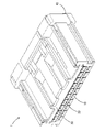
- FIG. 1 is a front perspective view of the connector in Example 1.
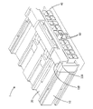
- FIG. FIG. 2 is a perspective view of the connector as seen from the rear side.
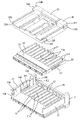
- FIG. 3 is an exploded perspective view of the connector, excluding terminal fittings, viewed from above the front side.
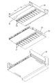
- FIG. 4 is an exploded perspective view of the connector, excluding terminal fittings, viewed from the lower rear side.
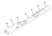
- FIG. 5 is a perspective view of a terminal fitting.
- FIG. 6 is a front view of the connector.
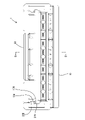
- FIG. 9 is a cross-sectional view taken along the line BB of FIG. 6.
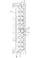
- FIG. 10 is a cross-sectional view taken along line CC of FIG. 9.
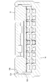
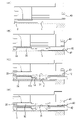
- FIG. 11A and 11B are explanatory diagrams illustrating the manufacturing process of the connector.
- the connector of the present disclosure is (1) A connector comprising a plurality of housings to be stacked, terminal fittings housed in the housings, and electric wires fixed to the terminal fittings and led out to the rear of the housing, a rear wall molded as a single piece or single part having a through hole for the wire to pass through; A separation regulating portion is formed on the rear wall portion for regulating the separation of the wires arranged in the stacking direction of the housing in the direction opposite to the other wires in the stacking direction.
- the separation restricting portion is formed in the rear wall portion molded as a single component or single part, the electric wire is pulled in the separation direction (opposite direction to the other electric wires). Also, the pulling force on the electric wire can be received by the rear wall portion. Therefore, the tensile force applied to the wires is less likely to be applied to the housing, and separation of the stacked housings can be suppressed.
- the housing has a plurality of terminal accommodating chambers arranged in a direction intersecting the stacking direction, the terminal fittings are accommodated in the terminal accommodating chambers, and the through holes are separate from the plurality of terminal accommodating chambers.
- the rear wall portion is integrally formed with one housing. According to this configuration, the number of members can be reduced compared to the case where the rear wall portion is a separate component from the housing. (4) It is preferable that the rear wall portion is positioned behind the housing where the rear wall portion is not formed.
- the housing has a plurality of terminal accommodating chambers arranged in a direction crossing the stacking direction, and the rear end opening edge of the terminal accommodating chamber of the housing where the rear wall portion is not formed has:
- a tapered guiding portion is formed. According to this configuration, the terminal fitting is guided forward by the tapered guiding portion immediately after passing through the through hole of the rear wall portion, so that it can be prevented from being caught on the rear end opening edge of the terminal accommodating chamber.
- the plurality of housings have locking portions for holding the plurality of housings in a stacked state, and the locking portions are provided only at both ends of the housings in the width direction intersecting with the direction in which the wires are led out. It is preferably formed in According to this configuration, the structure of the housing can be simplified by providing the locking portions only at both ends of the housing.
- FIG. 1 A first embodiment embodying the connector of the present disclosure will be described with reference to FIGS. 1 to 11.
- FIG. 1 the vertical directions shown in FIGS. 1 to 11 are defined as upward and downward.
- the left and right directions shown in FIGS. 9 and 11 are defined as forward and rearward, respectively.
- left and right shown in FIGS. 7, 8 and 10 are defined as right and left.
- the connector 1 of the first embodiment includes a first housing 10, a second housing 20, a third housing 30, a rear wall portion 40, and terminal fittings 50 (see FIG. 9). ) and an electric wire 60 .
- the first housing 10, the second housing 20, and the third housing 30 correspond to the "housing" of the present disclosure.
- the first housing 10, the second housing 20, and the third housing 30 are laminated.
- the rear wall portion 40 constitutes the wall portion on the rear side of the connector 1 .
- the terminal fittings 50 are housed in the first housing 10 and the second housing 20 .
- the electric wire 60 is fixed to the terminal fitting 50 .
- the electric wire 60 is led out rearward from the first housing 10 or the second housing 20 .
- the first housing 10, the second housing 20, and the third housing 30 are each a single component made of synthetic resin.
- the connector 1 has a first housing 10, a second housing 20, and a third housing 30 stacked in this order from below.
- the first housing 10 has a flat shape with its longitudinal direction extending in the horizontal direction.
- a plurality of first terminal receiving chambers 11 are provided in the first housing 10 .
- the first terminal accommodating chamber 11 corresponds to an example of a "terminal accommodating chamber”.
- a terminal fitting 50 is accommodated in the first terminal accommodating chamber 11 .
- 6 to 8 and 10 illustrate a state in which the terminal fittings 50 are accommodated only in some of the terminal accommodating chambers 11.
- the plurality of first terminal receiving chambers 11 are arranged in a line in a direction (horizontal direction) intersecting the stacking direction.
- the stacking direction means the stacking direction (vertical direction) of the first housing 10 , the second housing 20 , and the third housing 30 .
- the first terminal receiving chamber 11 is elongated in the front-rear direction, as shown in FIG. An opening 11 ⁇ /b>A that opens upward is provided on the rear end side of the first terminal receiving chamber 11 .
- the first housing 10 has a pair of side walls 12 as shown in FIG.
- the side wall 12 is elongated in the front-rear direction from the front end side to the rear end side of the first housing 10 .
- the front end of the side wall 12 is provided with a front bulging portion 13A that bulges inward in the left-right direction (toward the other side wall 12).
- the front bulging portion 13A is provided with a first recess 13B recessed outward in the left-right direction (on the side opposite to the other side wall 12).
- the first recess 13B opens forward.
- a recessed portion 14A recessed outward in the left-right direction is provided in the center of the side wall 12 in the front-rear direction.
- the recessed portion 14A has a rectangular shape elongated in the front-rear direction when viewed from the left-right direction.
- a locked piece 14B projecting inward in the left-right direction is provided on the lower end side of the recessed portion 14A. The locked piece 14B and the recessed portion 14A are elongated over the entire length in the front-rear direction.
- the rear end of the side wall 12 is provided with a rear bulging portion 15A that bulges outward and upward in the left-right direction.
- a first convex portion 15B and a second concave portion 15C are provided on the side wall 12 inside the rear bulging portion 15A in the left-right direction.
- the first convex portion 15B protrudes inward in the left-right direction from the upper end of the rear bulging portion 15A.
- the second concave portion 15C is provided adjacent to the lower side of the first convex portion 15B.
- the first protrusion 15B is recessed outward in the left-right direction.
- the rear wall part 40 is a single part made of synthetic resin.
- the rear wall portion 40 is formed integrally with the first housing 10, as shown in FIGS.
- “single part” means a single part in its as-molded state.
- “Single site” does not include a combination of multiple independent parts.
- the first housing 10 and the rear wall portion 40 constitute one component. Therefore, compared with the case where the rear wall portion 40 is a component separate from the housings 10, 20, 30, the number of members can be reduced.
- the rear wall portion 40 rises upward from the rear end of the first housing 10 .
- the rear wall portion 40 is a plate-like wall portion elongated in the left-right direction.
- the upper end of the rear wall portion 40 is positioned below the upper end of the side wall 12 .
- slits 41 are provided between the rear wall portion 40 and the pair of side walls 12 respectively. As a result, the side walls 12 are easily bent and deformed in the left-right direction.
- the rear wall portion 40 is provided with a plurality of through holes 42 as shown in FIGS.
- the through-holes 42 are not formed in parts or sites other than the rear wall portion 40 .
- the through-holes 42 are formed in two stages in the vertical direction and are arranged side by side in the left-right direction.
- the through hole 42 has a square shape when viewed from the front-rear direction.
- the through hole 42 allows the terminal fitting 50 and the electric wire 60 connected to the terminal fitting 50 to pass therethrough.
- the through hole 42 is partitioned so as to individually communicate with the first terminal accommodating chamber 11 and a second terminal accommodating chamber 21, which will be described later.
- the through-holes 42 are configured to individually communicate with the plurality of terminal accommodating chambers (the plurality of first terminal-accommodating chambers 11 and the plurality of second terminal-accommodating chambers 21), when the wires 60 are passed through the through-holes 42, Insertion of the terminal fittings 50 into the respective terminal accommodating chambers 11 and 21 is facilitated. Erroneous insertion of the terminal fitting 50 into each of the terminal accommodating chambers 11 and 21 can also be prevented.
- the lower through-hole 42 integrally communicates with the first terminal accommodating chamber 11 in the front-rear direction.
- the upper through-hole 42 communicates with the second terminal accommodating chamber 21 in the front-rear direction when the second housing 20 is stacked on the first housing 10 .
- the rear wall portion 40 is positioned behind the second housing 20 in a state where the second housing 20 is layered on the first housing 10, as shown in FIG. Specifically, the rear wall portion 40 contacts the second housing 20 from behind.
- the rear wall portion 40 is positioned behind the third housing 30 in a state in which the third housing 30 is layered on the first housing 10 and the second housing 20 . Specifically, the rear wall portion 40 contacts the third housing 30 from behind.
- the housings (the second housing 20 and the third housing 30) in which the rear wall portion 40 is not formed can be prevented from being displaced rearward, so there is no need to provide a lock for restricting rearward displacement.
- the rear wall portion 40 is formed with a first separation regulating portion 43 and a second separation regulating portion 44 .
- the first separation regulation part 43 and the second separation regulation part 44 correspond to an example of the "separation regulation part" of the present disclosure.
- the first separation regulating portion 43 and the second separation regulating portion 44 are such that the electric wires 60 arranged in the stacking direction of the first housing 10, the second housing 20, and the third housing 30 are separated from the other electric wires 60 in the stacking direction. It regulates separating in the opposite direction.
- the first separation restricting portion 43 is formed by the lower wall portion of the lower through hole 42 .
- the first separation restricting portion 43 is configured by a wall portion having wall surfaces (wall surfaces facing upward) parallel to the front-rear direction and the left-right direction.
- the second separation regulating portion 44 is formed by the upper wall portion of the upper through-hole 42 .
- the second separation restricting portion 44 is configured by a wall portion having wall surfaces (wall surfaces facing downward) parallel to the front-rear direction and the left-right direction.
- the second housing 20 has a flat shape with its length in the left-right direction.
- the rear wall portion 40 is not formed on the second housing 20 .
- a plurality of second terminal receiving chambers 21 are provided in the second housing 20 .
- the second terminal accommodating chamber 21 corresponds to an example of a "terminal accommodating chamber”.
- a terminal fitting 50 is accommodated in the second terminal accommodating chamber 21 .
- 6 to 8 and 10 illustrate a state in which the terminal fittings 50 are accommodated only in part of the second terminal accommodating chambers 21.
- the plurality of second terminal receiving chambers 21 are arranged in a row in a direction (horizontal direction) intersecting the stacking direction.
- the second terminal receiving chamber 21 is elongated in the front-rear direction, as shown in FIG.
- An opening 21 ⁇ /b>A that opens upward is provided on the rear end side of the second terminal accommodating chamber 21 .
- An upper wall portion 22 extending over the entire left-right direction of the second housing 20 is provided in front of the opening portion 21A.
- the upper wall portion 22 is one step higher than the front end of the second housing 20 .
- a guide portion 21B is formed at the rear end opening edge of the second terminal accommodating chamber 21.
- a rear end opening edge of the second terminal receiving chamber 21 has a U shape that opens upward when viewed from the rear.
- the guide portion 21B is tapered rearward. Specifically, the guide portion 21B is inclined downward toward the rear at the lower portion of the rear end opening edge of the second terminal receiving chamber 21, and the rear end opening edge of the second terminal receiving chamber 21 is inclined downward.
- the left and right side portions of are inclined outward in the left and right direction toward the rear.
- Locking pieces 23 are provided at both left and right ends of the second housing 20, as shown in FIGS.
- the locking piece 23 protrudes laterally outward.
- the locking piece 23 is long in the front-rear direction.
- the locking piece 23 is provided on the rear side of the upper wall portion 22 in the second housing 20 .
- the locking pieces 23 are locked to the locked pieces 14B in a state where the second housing 20 is laminated on the first housing 10.
- the locking piece 23 enters below the locked piece 14B in a state in which the second housing 20 is stacked on the first housing 10, and is engaged with the locked piece 14B. Contact from below.
- the locking piece 23 and the locked piece 14B correspond to an example of the "locking portion" of the present disclosure.
- the locking pieces 23 are formed only at both ends of the second housing 20 in the left-right direction (width direction intersecting with the lead-out direction of the electric wire 60). Therefore, the structure of the second housing 20 can be simplified.
- the engaged pieces 14B are formed only at both ends of the first housing 10 in the left-right direction. Therefore, the structure of the first housing 10 can be simplified.
- a plurality of first hooks 24 are provided on the lower surface of the second housing 20 so as to correspond to the plurality of first terminal receiving chambers 11, as shown in FIG.
- the first hook portion 24 protrudes downward from the bottom surface of the second housing 20 .
- the first hook portion 24 enters the opening portion 11A of the first terminal receiving chamber 11 from above and faces the front edge of the opening portion 11A and a projection 54 of the terminal fitting 50 to be described later from behind. do. This prevents the terminal fitting 50 from coming off rearward and restricts the forward movement of the second housing 20 with respect to the first housing 10 .
- the third housing 30 has a flat shape with its length in the left-right direction.
- the rear wall portion 40 is not formed on the third housing 30 .
- a bendable lock arm 31 projecting like a cantilever is provided in the center of the upper surface of the third housing 30 in the left-right direction.
- a corner portion of the front side portion of the third housing 30 is provided with a second convex portion 32A projecting outward in the left-right direction.
- Left and right side walls of the third housing 30 are provided with third recesses 32B recessed inward in the left-right direction so as to surround the second protrusions 32A.
- FIG. 6 in a state where the third housing 30 is stacked on the second housing 20, the front bulging portion 13A is inserted into the third concave portion 32B.
- the second convex portion 32A enters the first concave portion 13B.
- the rear ends of the left and right side walls of the third housing 30 are provided with fourth recesses 33A recessed inward in the left-right direction.
- a third protrusion 33B is provided that protrudes outward in the left-right direction.
- the first protrusion 15B is inserted into the fourth recess 33A.
- the rearward movement of the first projection 15B is restricted by the rear third projection 33B.
- a plurality of second hooks 34 are provided on the lower surface of the third housing 30 so as to correspond to the plurality of second terminal accommodating chambers 21, as shown in FIG.
- the second hook portion 34 protrudes downward from the bottom surface of the third housing 30 .
- the second hook portion 34 enters the opening portion 21A of the second terminal receiving chamber 21 from above, and engages the front edge of the opening portion 21A (the rear edge of the upper wall portion 22) and the terminal to be described later. It faces the projection 54 of the metal fitting 50 from behind. This prevents the terminal fitting 50 from coming off rearward and restricts the forward movement of the third housing 30 with respect to the second housing 20 .
- a stepped portion 35 is provided on the lower surface of the third housing 30 in front of the plurality of second hooking portions 34 so as to be lowered by one step. As shown in FIG. 9, the stepped portion 35 contacts the front end of the upper wall portion 22 from the front. This restricts the rearward movement of the third housing 30 with respect to the second housing 20 .
- the terminal fitting 50 is, for example, a female terminal fitting, as shown in FIG.
- the terminal fitting 50 is formed by punching a metal plate material into a predetermined shape and then bending the stamped metal plate material.
- the terminal fitting 50 has a rectangular tubular portion 51 , a first barrel 52 and a second barrel 53 .
- the rectangular tubular portion 51 has a cylindrical shape and accommodates a contact piece (not shown) that contacts a tab (not shown) of a mating male terminal fitting.
- a protrusion 54 protruding upward is provided at the rear end of the upper surface of the rectangular tubular portion 51 .
- the first barrel 52 crimps the lead wire 61 led out from the wire 60 .
- the second barrel 53 is fixed to the electric wire 60 by crimping.
- the rear wall portion 40 formed as a single portion is formed with the first separation regulating portion 43 and the second separation regulating portion 44 as shown in FIG. Therefore, even if the electric wire 60 is pulled in the separating direction (opposite direction to the other electric wires 60), the pulling force on the electric wire 60 can be received by the rear wall portion 40.
- FIG. For example, when the lower electric wire 60 shown in FIG. 9 is pulled downward and the upper electric wire 60 shown in FIG. , the upper electric wire 60 is received by the second separation restricting portion 44 .
- the rear wall portion 40 formed as a single part receives tensile forces in different directions, the tensile forces applied to the electric wires 60 are less likely to reach the respective housings 10, 20, 30, and each of the stacked housings 10, 20, 30 receives the tensile forces in different directions. Separation of the housings 10, 20, 30 can be suppressed.
- connector 1 is manufactured. First, as shown in FIG. 11(A), the first housing 10 is prepared. Subsequently, as shown in FIG. 11B, a terminal fitting 50 having an electric wire 60 connected to the first terminal accommodating chamber 11 of the first housing 10 through the through hole 42 on the lower side of the rear wall portion 40 is mounted. insert.
- the second housing 20 is stacked on the first housing 10 so that the second housing 20 is placed between the side walls 12 of the first housing 10 as shown in FIG.
- the locking piece 23 of the second housing 20 is locked to the locked piece 14B of the first housing 10 .
- the locking piece 23 climbs over the locked piece 14B and comes into contact with the locked piece 14B from below as shown in FIG. state.
- the rear end of the second housing 20 contacts the front end of the rear wall portion 40 .
- the through hole 42 of the rear wall portion 40 communicates with the second terminal accommodating chamber 21 .
- the first hook portion 24 of the second housing 20 is inserted into the opening portion 11A of the first terminal receiving chamber 11 from above, and the front edge of the opening portion 11A and the projection 54 (see FIG. 9) of the terminal fitting 50 are pushed backward. facing from As a result, the terminal fitting 50 is prevented from coming off rearward and the forward movement of the second housing 20 with respect to the first housing 10 is restricted.
- the terminal fitting 50 having the electric wire 60 connected to the second terminal accommodating chamber 21 of the second housing 20 is inserted through the through hole 42 on the upper side of the rear wall portion 40 . insert.
- the third housing 30 is stacked on the second housing 20, as shown in FIG.
- the rear end of the third housing 30 contacts the front end of the rear wall portion 40 .
- the front bulge 13A is inserted into the third recess 32B.
- the second convex portion 32A is inserted into the first concave portion 13B.
- the first protrusion 15B is inserted into the fourth recess 33A.
- the rearward movement of the first projection 15B is restricted by the rear third projection 33B.
- the second hook portion 34 of the third housing 30 is inserted into the opening 21A of the second terminal receiving chamber 21 from above, and the front edge of the opening 21A (the rear edge of the upper wall portion 22) ) and the projection 54 of the terminal fitting 50 from behind.
- the terminal fitting 50 is prevented from coming off rearward, and the forward movement of the third housing 30 with respect to the second housing 20 is restricted.
- the stepped portion 35 is brought into contact with the front end of the upper wall portion 22 from the front. This restricts the rearward movement of the third housing 30 with respect to the second housing 20 .
- the first separation regulating portion 43 and the second separation regulating portion 44 are formed in the rear wall portion 40 formed as a single part, so that the wires 60 are separated. Even if it is pulled in the direction (opposite to the other electric wires 60), the pulling force on the electric wires 60 can be received by the rear wall portion 40. - ⁇ Therefore, the tensile force applied to the electric wire 60 is less likely to reach the housings 10, 20, 30, and separation of the stacked housings 10, 20, 30 can be suppressed.
- the through holes 42 of the rear wall portion 40 are partitioned so as to individually communicate with the plurality of first terminal accommodating chambers 11 and the plurality of second terminal accommodating chambers 21 . According to this configuration, when the wire 60 is passed through the through hole 42 , the terminal fitting 50 can be easily inserted into the first terminal accommodating chamber 11 and the second terminal accommodating chamber 21 . Erroneous insertion of the terminal fitting 50 into the first terminal accommodating chamber 11 and the second terminal accommodating chamber 21 can also be prevented.
- the rear wall portion 40 is integrally formed with the first housing 10 . According to this configuration, the number of members can be reduced compared to the case where the rear wall portion 40 is a component separate from the first housing 10 .
- the rear wall portion 40 is located behind the housings (the first housing 10 and the second housing 20) in which the rear wall portion 40 is not formed. According to this configuration, it is possible to prevent the housings (the first housing 10 and the second housing 20) in which the rear wall portion 40 is not formed from being displaced rearward. .
- a tapered guide portion 21B is formed at the rear end opening edge of the second terminal accommodating chamber 21 of the second housing 20 . According to this configuration, since the terminal fitting 50 is guided forward by the tapered guide portion 21B immediately after passing through the through hole 42 of the rear wall portion 40, the rear end opening edge of the second terminal accommodating chamber 21 is guided forward. You can prevent getting caught.
- the locking pieces 23 are formed only at both ends of the second housing 20 in the left-right direction (the width direction intersecting with the lead-out direction of the electric wires 60). Therefore, the structure of the second housing 20 can be simplified.
- the engaged pieces 14B are formed only at both ends of the first housing 10 in the left-right direction. Therefore, the structure of the first housing 10 can be simplified.
- the rear wall portion 40 is integrally formed with the first housing 10 in the first embodiment, it may be integrally formed with other housings (the second housing 20 and the third housing 30).
- the through hole of the rear wall portion 40 may be a single large opening that communicates with all the terminal accommodating chambers.
- the through hole may have a slit shape communicating with all the terminal accommodating chambers formed in one housing.
- the rear wall portion 40 is formed integrally with the first housing 10 in the first embodiment, the rear wall portion may be formed as a single component separate from the first housing 10 .
- “single piece” refers to a single piece in its as-molded state.
- “Single part” does not include a combination of multiple independent parts.
- the locking pieces 23 are formed only at both ends of the second housing 20 in the left-right direction, but they may be formed at the central portion in the left-right direction.
- the engaged pieces 14B are formed only at both ends of the first housing 10 in the left-right direction, they may be formed at the central portion in the left-right direction.
- Second housing (housing) 31 Lock arm 32A Second convex portion 32B Third concave portion 33A Fourth concave portion 33B Third convex portion 34 Second hook portion 35 Stepped portion 40 Rear wall portion 41 Slit 42 Through hole 43 ...First separation regulation part (separation regulation part) 44 . . . Second separation control section (separation control section) 50... Terminal fitting 51... Rectangular tubular portion 52... First barrel 53... Second barrel 54... Projection 60... Electric wire 61... Conducting wire
Landscapes
- Connector Housings Or Holding Contact Members (AREA)
Priority Applications (2)
| Application Number | Priority Date | Filing Date | Title |
|---|---|---|---|
| US18/570,573 US12700695B2 (en) | 2021-06-18 | 2022-05-31 | Connector |
| CN202280040959.0A CN117441270A (zh) | 2021-06-18 | 2022-05-31 | 连接器 |
Applications Claiming Priority (2)
| Application Number | Priority Date | Filing Date | Title |
|---|---|---|---|
| JP2021101382A JP7498898B2 (ja) | 2021-06-18 | 2021-06-18 | コネクタ |
| JP2021-101382 | 2021-06-18 |
Publications (1)
| Publication Number | Publication Date |
|---|---|
| WO2022264798A1 true WO2022264798A1 (ja) | 2022-12-22 |
Family
ID=84527376
Family Applications (1)
| Application Number | Title | Priority Date | Filing Date |
|---|---|---|---|
| PCT/JP2022/022027 Ceased WO2022264798A1 (ja) | 2021-06-18 | 2022-05-31 | コネクタ |
Country Status (4)
| Country | Link |
|---|---|
| US (1) | US12700695B2 (cg-RX-API-DMAC7.html) |
| JP (1) | JP7498898B2 (cg-RX-API-DMAC7.html) |
| CN (1) | CN117441270A (cg-RX-API-DMAC7.html) |
| WO (1) | WO2022264798A1 (cg-RX-API-DMAC7.html) |
Cited By (1)
| Publication number | Priority date | Publication date | Assignee | Title |
|---|---|---|---|---|
| US20240347962A1 (en) * | 2023-04-14 | 2024-10-17 | Sumitomo Wiring Systems, Ltd. | Connector, system and method of assembling connector |
Citations (7)
| Publication number | Priority date | Publication date | Assignee | Title |
|---|---|---|---|---|
| JPH02223171A (ja) * | 1988-11-24 | 1990-09-05 | Yazaki Corp | 多段式コネクタ並びに電線圧接方法 |
| JPH1140242A (ja) * | 1997-07-14 | 1999-02-12 | Sumitomo Wiring Syst Ltd | ブロックコネクタ |
| JP2000357557A (ja) * | 1999-06-15 | 2000-12-26 | Yazaki Corp | 防水コネクタ及び該防水コネクタの組付方法 |
| JP2002352893A (ja) * | 2001-05-25 | 2002-12-06 | Yazaki Corp | コネクタ |
| JP2002367714A (ja) * | 2001-06-04 | 2002-12-20 | Yazaki Corp | ワイヤーハーネスおよびワイヤーハーネスの製造方法 |
| JP2004080918A (ja) * | 2002-08-19 | 2004-03-11 | Sumitomo Wiring Syst Ltd | 電気接続箱および該電気接続箱の組立方法 |
| JP2007026764A (ja) * | 2005-07-13 | 2007-02-01 | Sumitomo Wiring Syst Ltd | 防水コネクタ |
Family Cites Families (2)
| Publication number | Priority date | Publication date | Assignee | Title |
|---|---|---|---|---|
| DE3938964A1 (de) * | 1988-11-24 | 1990-05-31 | Yazaki Corp | Mehrfachstufenverbinder |
| JP7042419B2 (ja) | 2018-10-24 | 2022-03-28 | 住友電装株式会社 | 積層コネクタ |
-
2021
- 2021-06-18 JP JP2021101382A patent/JP7498898B2/ja active Active
-
2022
- 2022-05-31 WO PCT/JP2022/022027 patent/WO2022264798A1/ja not_active Ceased
- 2022-05-31 CN CN202280040959.0A patent/CN117441270A/zh active Pending
- 2022-05-31 US US18/570,573 patent/US12700695B2/en active Active
Patent Citations (7)
| Publication number | Priority date | Publication date | Assignee | Title |
|---|---|---|---|---|
| JPH02223171A (ja) * | 1988-11-24 | 1990-09-05 | Yazaki Corp | 多段式コネクタ並びに電線圧接方法 |
| JPH1140242A (ja) * | 1997-07-14 | 1999-02-12 | Sumitomo Wiring Syst Ltd | ブロックコネクタ |
| JP2000357557A (ja) * | 1999-06-15 | 2000-12-26 | Yazaki Corp | 防水コネクタ及び該防水コネクタの組付方法 |
| JP2002352893A (ja) * | 2001-05-25 | 2002-12-06 | Yazaki Corp | コネクタ |
| JP2002367714A (ja) * | 2001-06-04 | 2002-12-20 | Yazaki Corp | ワイヤーハーネスおよびワイヤーハーネスの製造方法 |
| JP2004080918A (ja) * | 2002-08-19 | 2004-03-11 | Sumitomo Wiring Syst Ltd | 電気接続箱および該電気接続箱の組立方法 |
| JP2007026764A (ja) * | 2005-07-13 | 2007-02-01 | Sumitomo Wiring Syst Ltd | 防水コネクタ |
Cited By (1)
| Publication number | Priority date | Publication date | Assignee | Title |
|---|---|---|---|---|
| US20240347962A1 (en) * | 2023-04-14 | 2024-10-17 | Sumitomo Wiring Systems, Ltd. | Connector, system and method of assembling connector |
Also Published As
| Publication number | Publication date |
|---|---|
| JP7498898B2 (ja) | 2024-06-13 |
| JP2023000511A (ja) | 2023-01-04 |
| US12700695B2 (en) | 2026-08-04 |
| US20240283190A1 (en) | 2024-08-22 |
| CN117441270A (zh) | 2024-01-23 |
Similar Documents
| Publication | Publication Date | Title |
|---|---|---|
| JP5381492B2 (ja) | 雌端子金具 | |
| CN107710517B (zh) | 接头连接器 | |
| CN110534951B (zh) | 连接器 | |
| JP6393301B2 (ja) | コネクタ | |
| JP5098875B2 (ja) | コネクタ | |
| EP0963009B1 (en) | A construction for preventing an error assembling of a connector housing and a cover and a connector comprising the same | |
| WO2018168368A1 (ja) | 端子ユニット及びコネクタ | |
| JP2024143303A (ja) | コネクタ | |
| JP2012174432A (ja) | ジョイントコネクタ | |
| WO2023095552A1 (ja) | コネクタ | |
| CN110323613B (zh) | 连接器及端子零件 | |
| JP7498898B2 (ja) | コネクタ | |
| JP7704621B2 (ja) | ジョイントコネクタ | |
| JP5183315B2 (ja) | コネクタ | |
| WO2020105382A1 (ja) | コネクタ | |
| JP7476825B2 (ja) | コネクタ | |
| CN102683973A (zh) | 连接器 | |
| WO2023140141A1 (ja) | 端子及びコネクタ | |
| JP7786909B2 (ja) | コネクタ | |
| US11728589B2 (en) | Connector | |
| WO2023042619A1 (ja) | 積層コネクタ | |
| JP2012038551A (ja) | コネクタ | |
| JP2023102385A (ja) | コネクタ | |
| JP4139268B2 (ja) | 電気接続箱 | |
| JP5810834B2 (ja) | コネクタ |
Legal Events
| Date | Code | Title | Description |
|---|---|---|---|
| 121 | Ep: the epo has been informed by wipo that ep was designated in this application |
Ref document number: 22824792 Country of ref document: EP Kind code of ref document: A1 |
|
| DPE1 | Request for preliminary examination filed after expiration of 19th month from priority date (pct application filed from 20040101) | ||
| WWE | Wipo information: entry into national phase |
Ref document number: 202280040959.0 Country of ref document: CN |
|
| WWE | Wipo information: entry into national phase |
Ref document number: 18570573 Country of ref document: US |
|
| NENP | Non-entry into the national phase |
Ref country code: DE |
|
| 122 | Ep: pct application non-entry in european phase |
Ref document number: 22824792 Country of ref document: EP Kind code of ref document: A1 |
|
| WWG | Wipo information: grant in national office |
Ref document number: 18570573 Country of ref document: US |