WO2022264281A1 - 電波到来方向推定装置、電波到来方向推定方法、及び電波到来方向推定プログラム - Google Patents
電波到来方向推定装置、電波到来方向推定方法、及び電波到来方向推定プログラム Download PDFInfo
- Publication number
- WO2022264281A1 WO2022264281A1 PCT/JP2021/022733 JP2021022733W WO2022264281A1 WO 2022264281 A1 WO2022264281 A1 WO 2022264281A1 JP 2021022733 W JP2021022733 W JP 2021022733W WO 2022264281 A1 WO2022264281 A1 WO 2022264281A1
- Authority
- WO
- WIPO (PCT)
- Prior art keywords
- antenna
- unit
- wave
- arrival
- antenna angle
- Prior art date
- Legal status (The legal status is an assumption and is not a legal conclusion. Google has not performed a legal analysis and makes no representation as to the accuracy of the status listed.)
- Ceased
Links
Images

Classifications
-
- G—PHYSICS
- G01—MEASURING; TESTING
- G01S—RADIO DIRECTION-FINDING; RADIO NAVIGATION; DETERMINING DISTANCE OR VELOCITY BY USE OF RADIO WAVES; LOCATING OR PRESENCE-DETECTING BY USE OF THE REFLECTION OR RERADIATION OF RADIO WAVES; ANALOGOUS ARRANGEMENTS USING OTHER WAVES
- G01S3/00—Direction-finders for determining the direction from which infrasonic, sonic, ultrasonic or electromagnetic waves, or particle emission, not having a directional significance, are being received
- G01S3/02—Direction-finders for determining the direction from which infrasonic, sonic, ultrasonic or electromagnetic waves, or particle emission, not having a directional significance, are being received using radio waves
- G01S3/14—Systems for determining direction or deviation from predetermined direction
- G01S3/16—Systems for determining direction or deviation from predetermined direction using amplitude comparison of signals derived sequentially from receiving antennas or antenna systems having differently-oriented directivity characteristics or from an antenna system having periodically-varied orientation of directivity characteristic
- G01S3/20—Systems for determining direction or deviation from predetermined direction using amplitude comparison of signals derived sequentially from receiving antennas or antenna systems having differently-oriented directivity characteristics or from an antenna system having periodically-varied orientation of directivity characteristic derived by sampling signal received by an antenna system having periodically-varied orientation of directivity characteristic
-
- G—PHYSICS
- G01—MEASURING; TESTING
- G01S—RADIO DIRECTION-FINDING; RADIO NAVIGATION; DETERMINING DISTANCE OR VELOCITY BY USE OF RADIO WAVES; LOCATING OR PRESENCE-DETECTING BY USE OF THE REFLECTION OR RERADIATION OF RADIO WAVES; ANALOGOUS ARRANGEMENTS USING OTHER WAVES
- G01S3/00—Direction-finders for determining the direction from which infrasonic, sonic, ultrasonic or electromagnetic waves, or particle emission, not having a directional significance, are being received
- G01S3/02—Direction-finders for determining the direction from which infrasonic, sonic, ultrasonic or electromagnetic waves, or particle emission, not having a directional significance, are being received using radio waves
- G01S3/14—Systems for determining direction or deviation from predetermined direction
- G01S3/58—Rotating or oscillating beam systems using continuous analysis of received signal for determining direction in the plane of rotation or oscillation or for determining deviation from a predetermined direction in such a plane
- G01S3/66—Narrow-beam systems producing in the receiver a pulse-type envelope signal of the carrier wave of the beam, the timing of which is dependent upon the angle between the direction of the transmitter from the receiver and a reference direction from the receiver; Overlapping broad-beam systems defining in the receiver a narrow zone and producing a pulse-type envelope signal of the carrier wave of the beam, the timing of which is dependent upon the angle between the direction of the transmitter from the receiver and a reference direction from the receiver
Definitions
- the present invention relates to a radio wave direction of arrival estimation device, a radio wave direction of arrival estimation method, and a radio wave direction of arrival estimation program.
- Non-Patent Document 1 discloses a method of estimating the direction of arrival of radio waves using an array antenna using the MUSIC algorithm (MUltiple SIgnal Classification).
- the present invention provides a direction-of-arrival estimation apparatus, a direction-of-arrival estimation method, and a program for estimating the direction of arrival of radio waves that can estimate the direction of arrival of radio waves without using an array antenna with strong directivity. aim.
- An apparatus for estimating a direction of arrival of radio waves includes: an antenna angle acquisition unit configured to acquire an antenna angle indicating a plurality of different directions in which an antenna having a non-uniform antenna pattern is sequentially directed; a reception intensity measurement unit that measures the reception intensity of the radio wave received by the antenna at each antenna angle acquired by the unit; a reception intensity measured by the antenna angle acquired by the antenna angle acquisition unit and the reception intensity measured by the reception intensity measurement unit; a matching degree calculation unit for calculating a degree of matching of the antenna with the antenna pattern for each antenna angle acquired by the antenna angle acquiring unit; and an estimating unit for estimating the direction of arrival.
- a radio wave direction-of-arrival estimation method includes: an antenna angle obtaining step of obtaining antenna angles indicating a plurality of different directions in which an antenna having a non-uniform antenna pattern is sequentially directed; A reception intensity measurement step of measuring the reception intensity of the radio wave received by the antenna at each antenna angle, and the acquired antenna angle, the degree of matching between the acquired antenna angle, the measured reception intensity, and the antenna pattern of the antenna. and an estimating step of estimating the antenna angle at which the calculated degree of matching is the maximum as the direction of arrival of the radio wave.
- the direction of arrival of radio waves can be estimated without using an array antenna with strong directivity.
- FIG. 1 It is a figure which shows the structural example of a communication apparatus.
- (a) is a diagram illustrating reception strength of radio waves received by an antenna at three different antenna angles.
- (b) is a diagram illustrating three antenna angles and radio wave intensities after separating delayed wave components, noise, and the like.
- (a) is a figure which illustrates the antenna pattern of an antenna.
- (b) is a diagram schematically showing a result of the estimation unit estimating the direction of arrival of radio waves using the antenna pattern.
- 4 is a flow chart showing an operation example of the direction-of-arrival estimation device for radio waves according to the embodiment;
- 4A is a diagram illustrating antenna pattern data stored in an antenna pattern storage unit;
- FIG. 1 is a diagram illustrating a hardware configuration example of a radio wave direction-of-arrival estimation apparatus according to an embodiment
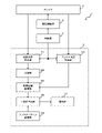
- FIG. 1 is a diagram showing a configuration example of a communication device 1. As shown in FIG.
- the communication device 1 includes an antenna 2, a rotation drive section 3, a control section 4, and a radio wave direction-of-arrival estimation device 5 according to one embodiment, and has a function as a receiving station.
- the antenna 2 is provided rotatably in the horizontal direction, for example, receives a radio wave (signal) transmitted from a low frequency band transmission station such as the VHF band, and transmits the received signal to the radio wave direction-of-arrival estimation device 5. Output.
- the antenna pattern (radiation pattern) of the antenna 2 is non-uniform (see FIG. 4). It should be noted that the non-uniformity of the antenna pattern indicates weak directivity rather than omnidirectionality.
- the rotation drive unit 3 drives the antenna 2 to rotate, for example, in the horizontal direction according to the control of the control unit 4, and sequentially turns the antenna 2 in all directions of 360 degrees.
- the control unit 4 controls the rotary drive unit 3 and the radio wave direction-of-arrival estimation device 5 according to the operator's operation on the operation unit (not shown). Note that the antenna 2 may be oriented in any direction by the operator's hand, regardless of the rotation drive unit 3 and the control unit 4 .
- the radio wave direction-of-arrival estimation device 5 has an antenna angle acquisition unit 50 , a reception strength measurement unit 51 , a separation unit 52 , an acquired information storage unit 53 , an antenna pattern storage unit 54 , a match calculation unit 55 , and an estimation unit 56 .
- the antenna angle acquisition unit 50 acquires antenna angles indicating a plurality of different directions in which the antenna 2 rotated by the rotation drive unit 3 is sequentially directed, and provides the received signal strength measurement unit 51 and the acquired information storage unit 53 with the antenna angles. Output.
- the antenna angle acquisition unit 50 may receive data indicating the antenna angle from the antenna 2 or may acquire the data from the control unit 4 . Further, the antenna angle acquisition unit 50 may acquire each antenna angle from data input by an operator to an operation unit (not shown).
- the reception intensity measurement unit 51 associates and measures the reception intensity of radio waves received by the antenna 2 at each antenna angle acquired by the antenna angle acquisition unit 50 , and outputs the measurement result to the separation unit 52 .
- the reception strength measurement unit 51 measures the reception strength at a plurality of equally spaced antenna angles.
- the reception strength measurement unit 51 determines all or part of the antenna angles for which the reception strength is to be measured, both ends of the settable antenna angle (maximum angle and minimum angle), and antenna angles separated at equal intervals in the remaining range. may be set to measure the received strength of radio waves.
- the reception intensity measurement unit 51 may acquire the reception intensity for each antenna angle from the reception intensity measurement data input by the operator to the operation unit (not shown).
- the separation unit 52 separates, for example, the delayed wave component and noise from the received strength measured by the received strength measurement unit 51, and acquires data in which the received strength of a predetermined incoming wave or delayed wave and the antenna angle are associated with each other. Output to the information storage unit 53 .
- the separation unit 52 separates the incoming wave and the delayed wave so as not to contain interference waves and noise by correlation between a known pattern such as a synchronization signal transmitted by the transmitting station and the received signal.
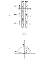
- FIG. 2 is a diagram exemplifying data output to the acquired information storage unit 53 after the separation unit 52 separates delayed wave components, noise, and the like.
- FIG. 2A is a diagram illustrating reception strengths (vertical axis) of radio waves received by the antenna 2 at three different antenna angles.
- FIG. 2B is a diagram illustrating three antenna angles and radio wave intensities after separating delayed wave components, noise, and the like.
- the radio waves transmitted by the transmitting station and propagated via multipath are measured by the receiving station as if the incoming wave and the delayed wave arrived from a certain direction with a certain intensity. At this time, the directions in which the arriving waves and delayed waves arrive are constant (true value/constant value).
- the measured value of the reception strength will increase or decrease depending on the characteristics (directivity) of the angle at which the antenna is directed. That is, the received strength is distorted differently depending on the direction in which the antenna is directed, and is not uniform.
- the antenna pattern storage unit 54 stores the directivity (distortion characteristic: antenna pattern) of the antenna 2
- the radio wave direction-of-arrival estimation device 5 uses the antenna pattern to determine the direction of arrival (true value). to estimate
- the antenna 2 receives incoming waves and delayed waves with different reception strengths.
- the separating unit 52 receives incoming waves or delayed waves (or second delayed waves) of the same propagation time received at the antenna angles A, B, and C of the antenna 2 respectively. (Fig. 2(a)).
- the separating unit 52 separates the received intensity for each arriving wave having the same propagation time (or delayed wave having the same propagation time) at the antenna angles A, B, and C due to the rotation of the antenna 2. is output to the acquired information storage unit 53 .
- the data output from the separation unit 52 to the acquired information storage unit 53 is a combination of the values of the antenna angles A, B, and C and the reception intensity of each antenna angle, so the data shown in FIG. corresponds to the three vectors
- the degree-of-match calculation unit 55 which will be described later, expands or contracts the combination of the values of the antenna angles A, B, and C and the reception strength of each antenna angle as a whole with reference to the origin, so that the combination of the antenna pattern and the Facilitates comparison.
- the true direction of arrival of radio waves can be estimated by rotating the combination of the reception intensities of the antenna angles for the same propagation time after being expanded or reduced with respect to the origin, with respect to the origin. .
- the separating unit 52 may separate each arriving wave having the same propagation time or each delayed wave having the same propagation time for each antenna angle. For example, if it is not easy to separate the first arriving wave, the separating unit 52 outputs the separated data for each delayed wave having the same propagation time to the acquired information storage unit 53 . That is, the radio wave direction-of-arrival estimation device 5 can estimate the direction of arrival of the radio waves at the reception intensity measurement time for each of the arriving waves with the same propagation time or the delayed waves with the same propagation time.
- the acquired information storage unit 53 (FIG. 1) stores, for example, data indicating the antenna angle acquired by the antenna angle acquisition unit 50, and data in which the reception intensity of the predetermined incoming wave separated by the separation unit 52 and the antenna angle are associated with each other. is stored, and output in response to access from the degree-of-match calculation unit 55 .
- the antenna pattern storage unit 54 stores data indicating the antenna pattern of the antenna 2 (gain for each antenna angle), and outputs it in response to access from the matching degree calculation unit 55 .
- the matching degree calculation unit 55 reads and acquires the data stored in the acquired information storage unit 53 and the data stored in the antenna pattern storage unit 54, and performs matching (comparison of matching degrees).
- the matching degree calculation unit 55 calculates the degree of matching between the antenna angle acquired by the antenna angle acquisition unit 50 and the reception intensity measured by the reception intensity measurement unit 51 and the antenna pattern of the antenna 2. It is calculated for each acquired antenna angle and output to the estimation unit 56 .
- the matching degree calculation unit 55 calculates the antenna angle acquired by the antenna angle acquisition unit 50, the reception intensity after the separation unit 52 separates the delayed wave component and noise, and the antenna pattern of the antenna 2. is calculated for each antenna angle acquired by the antenna angle acquiring unit 50 and output to the estimating unit 56 .
- the matching degree calculation unit 55 calculates the received power at an arbitrary antenna angle, the received power at an antenna angle close to the average value of the received power, and the antenna with the maximum received power.
- the received intensity at another antenna angle may be corrected based on the received intensity at an angle or the received intensity at a predetermined antenna angle.
- the degree-of-match calculation unit 55 expands or contracts the combination of the values of the antenna angles A, B, and C and the reception strength of each antenna angle as a whole with reference to the origin, and performs matching with the antenna pattern. you can go
- the degree-of-match calculation unit 55 compares the received intensity of the incoming wave (or delayed wave) at each antenna angle for the same propagation time with the antenna pattern to calculate the degree of match. For example, the degree-of-match calculation unit 55 rotates the combination of the reception intensities of the respective antenna angles that have been enlarged or reduced with respect to the origin as a whole with respect to the origin, and calculates the degree of coincidence with the antenna pattern for each direction. calculated by
- the degree-of-match calculation unit 55 does not have to use all the data of the reception strength measured during the same propagation time.
- the degree-of-match calculation unit 55 does not use, as an exclusion target, reception intensity data that is significantly different from the antenna pattern, as in a specific operation example of the direction-of-arrival estimation device 5, which will be described later with reference to FIG. , the degree of matching with the antenna pattern is calculated.
- the distance from the transmitting station to the antenna 2 is long, the reception strength at each antenna angle will be small, so it is conceivable that the accuracy will decrease when comparing with the antenna pattern and calculating the degree of matching.
- the degree-of-match calculation unit 55 first expands (or reduces) the overall combination of reception intensities at the respective antenna angles with reference to the origin, and calculates the magnitude of the reception intensities at the respective antenna angles to be matched. Perform processing to approximate the size of the pattern. At this time, the degree-of-match calculation unit 55 excludes data estimated to be an abnormal value with a large deviation, as will be described later with reference to FIG.
- the degree-of-match calculation unit 55 rotates the object to be matched with the size closer to the origin, and calculates the degree of match with the antenna pattern for each direction, thereby improving the accuracy of calculation of the degree of match.
- the degree-of-match calculation unit 55 may select a combination that minimizes the sum of the absolute values of gain differences as a method of comparing the degree of match between the angle and received intensity of the incoming wave and the antenna pattern. A combination that minimizes the sum of squares of absolute values may be selected.
- the estimating unit 56 estimates that the antenna angle at which the degree of matching calculated by the degree of matching calculating unit 55 is the maximum is the direction of arrival of radio waves to the communication device 1 .
- the maximum degree of matching is, for example, the combination that minimizes the difference between the antenna angle and reception intensity and the antenna pattern.
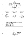
- FIG. 3 is a diagram illustrating the directions of arrival of radio waves estimated by the estimation unit 56.
- FIG. 3A is a diagram illustrating an antenna pattern of the antenna 2.
- FIG. 3B is a diagram schematically showing the result of estimating the direction of arrival of radio waves by the estimator 56 using the antenna pattern.
- the estimating unit 56 calculates, for example, the reception intensity of each antenna angle (see FIG. 2(b)) calculated by enlarging (or reducing) the matching degree calculation unit 55 so as to approach the size of the antenna pattern, with the origin as a reference. After rotation, the antenna angle (FIG. 3(b)) at which the degree of matching with the antenna pattern (FIG. 3(a)) is the maximum is estimated as the direction of arrival of radio waves to the communication apparatus 1.
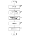
- FIG. 4 is a flow chart showing an operation example of the radio wave direction-of-arrival estimation device 5 according to one embodiment.
- the radio wave direction-of-arrival estimation device 5 receives a signal transmitted by a transmitting station via a rotating antenna 2 (S100), and acquires incoming waves as reception strengths for a plurality of antenna angles ( S102).
- the direction-of-arrival estimation device 5 selects (extracts) arriving waves with the same order of arrival at each antenna angle (S104), and calculates the degree of matching between the antenna angle and reception strength and the antenna pattern as the antenna angle is calculated for each (S106).
- the radio wave direction-of-arrival estimation device 5 estimates that the antenna angle with the highest degree of matching is the direction of arrival of radio waves for the communication device 1 (S108). In other words, the radio wave direction-of-arrival estimation device 5 estimates the direction of arrival of radio waves by combining the antenna pattern and the actually measured antenna angle.
- FIG. 5 is a diagram showing a specific operation example when the radio wave direction-of-arrival estimation device 5 estimates the radio wave arrival method. Here, it is assumed that only one wave has arrived.
- FIG. 5(a) is a diagram illustrating antenna pattern data stored in the antenna pattern storage unit 54 (FIG. 1).
- FIG. 5B is a diagram illustrating the correspondence between the antenna angle acquired by the antenna angle acquisition unit 50 and the reception intensity measured by the reception intensity measurement unit 51 when the antenna 2 rotates.
- FIG. 5(c) is a diagram exemplifying processing performed when the matching degree calculation unit 55 calculates the matching degree.
- FIG. 5(d) is a diagram exemplifying the result of estimating the direction of arrival of radio waves by the estimating unit 56. As shown in FIG.
- the antenna pattern storage unit 54 stores data indicating an antenna pattern indicated by a combination of a plurality of angles (directions) and gains in the range of -179 degrees to +180 degrees, for example. ing.
- the matching degree calculation unit 55 calculates, for example, a combination of measured angles (for example, the difference between the angle D and the angle E, and the difference between the angle E and the angle F with the angle E as the center) from the data stored in the antenna pattern storage unit 3 points) are extracted.
- the degree-of-match calculation unit 55 acquires a plurality of sets (Example 1, Example 2, etc.) from the antenna pattern storage unit 54, for example, as sets of the following three points.
- Example 1 -45 degrees, -5dB 0 degrees, 0 dB +45 degrees, -5dB (Example 2) 0 degrees, 0 dB +45 degrees, -5dB +90 degrees, -20dB
- the matching degree calculation unit 55 acquires the measured data as shown in FIG. 5(b) from the acquired information storage unit 53. In addition, as illustrated in FIG. 5C, the matching degree calculation unit 55 calculates the relative power and the inversion angle (replacement of ⁇ ) with respect to the maximum value for the data of each antenna angle measured as follows. do.
- the matching degree calculation unit 55 calculates (antenna pattern dB) - (measurement result dB) in order from the smaller antenna angle, and excludes data with a large ⁇ difference as being unable to be measured. .
- the matching degree calculation unit 55 expands (or reduces) the reception strength for each antenna angle with reference to the origin so as to compensate for the influence of attenuation of the reception power caused by the distance from the transmitting station. Exclude data that are estimated to deviate from the pattern.
- the degree-of-match calculation unit 55 calculates and stores the difference with respect to the antenna pattern using results other than data to be excluded.
- 11 dB
- the estimating unit 56 acquires each data stored in the matching degree calculating unit 55, and selects a combination that minimizes the difference between the antenna angle and reception intensity and the antenna pattern (maximum matching degree).
- the combination of example 1 is selected.
- the estimating unit 56 performs matching (matching degree comparison) between the reception strength of each antenna angle and the antenna pattern (antenna angle and gain) for incoming waves measured at a plurality of antenna angles. , the direction of arrival of each incoming wave is estimated (FIG. 5(d)).
- the direction-of-arrival estimation device 5 estimates the direction of arrival of radio waves as the antenna angle at which the matching degree calculated by the degree-of-matching calculation unit 55 is maximum. , the direction of arrival of radio waves can be estimated. That is, the direction-of-arrival estimator 5 of radio waves can easily and easily detect relatively low-frequency radio waves such as the VHF band without preparing an array antenna with strong directivity for estimating the direction of arrival of radio waves. A direction of arrival can be estimated at low cost.
- the direction-of-arrival estimation device 5 receives the difference (C/N) between the state in which the transmitting station stops transmitting the signal and the state in which the transmitting station transmits the signal. May be used instead of strength.
- each function of the direction-of-arrival estimation device 5 may be configured partially or entirely by hardware such as a PLD (Programmable Logic Device) or FPGA (Field Programmable Gate Array), or a processor such as a CPU. may be configured as a program executed by a PLD (Programmable Logic Device) or FPGA (Field Programmable Gate Array), or a processor such as a CPU. may be configured as a program executed by
- the radio wave direction-of-arrival estimation device 5 can be realized using a computer and a program, and the program can be recorded on a storage medium or provided through a network.
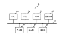
- FIG. 6 is a diagram showing a hardware configuration example of the radio wave direction-of-arrival estimation device 5 according to one embodiment.
- the radio wave direction-of-arrival estimation device 5 has an input unit 60, an output unit 61, a communication unit 62, a CPU 63, a memory 64, and an HDD 65 connected via a bus 66, and functions as a computer.
- the direction-of-arrival estimation device 5 is configured to be able to input/output data to/from a computer-readable storage medium 67 .
- the input unit 60 is, for example, a keyboard and a mouse.
- the output unit 61 is, for example, a display device such as a display.
- the communication unit 62 is, for example, a wired or wireless network interface.
- the CPU 63 controls each part that constitutes the direction-of-arrival estimation device 5 and performs predetermined processing.
- the memory 64 and the HDD 65 correspond to the obtained information storage section 53 and the antenna pattern storage section 54 which store data and the like.
- the storage medium 67 can store a program or the like for executing the functions of the direction-of-arrival estimation device 5 . Note that the architecture constituting the direction-of-arrival estimation apparatus 5 is not limited to the example shown in FIG.
Landscapes
- Physics & Mathematics (AREA)
- Engineering & Computer Science (AREA)
- General Physics & Mathematics (AREA)
- Radar, Positioning & Navigation (AREA)
- Remote Sensing (AREA)
- Variable-Direction Aerials And Aerial Arrays (AREA)
- Radio Transmission System (AREA)
Priority Applications (3)
| Application Number | Priority Date | Filing Date | Title |
|---|---|---|---|
| PCT/JP2021/022733 WO2022264281A1 (ja) | 2021-06-15 | 2021-06-15 | 電波到来方向推定装置、電波到来方向推定方法、及び電波到来方向推定プログラム |
| JP2023528818A JP7597218B2 (ja) | 2021-06-15 | 2021-06-15 | 電波到来方向推定装置、電波到来方向推定方法、及び電波到来方向推定プログラム |
| US18/569,710 US12656442B2 (en) | 2021-06-15 | 2021-06-15 | Radio wave arrival direction estimation device, radio wave arrival direction estimation method, and radio wave arrival direction estimation program |
Applications Claiming Priority (1)
| Application Number | Priority Date | Filing Date | Title |
|---|---|---|---|
| PCT/JP2021/022733 WO2022264281A1 (ja) | 2021-06-15 | 2021-06-15 | 電波到来方向推定装置、電波到来方向推定方法、及び電波到来方向推定プログラム |
Publications (1)
| Publication Number | Publication Date |
|---|---|
| WO2022264281A1 true WO2022264281A1 (ja) | 2022-12-22 |
Family
ID=84526332
Family Applications (1)
| Application Number | Title | Priority Date | Filing Date |
|---|---|---|---|
| PCT/JP2021/022733 Ceased WO2022264281A1 (ja) | 2021-06-15 | 2021-06-15 | 電波到来方向推定装置、電波到来方向推定方法、及び電波到来方向推定プログラム |
Country Status (3)
| Country | Link |
|---|---|
| US (1) | US12656442B2 (cg-RX-API-DMAC7.html) |
| JP (1) | JP7597218B2 (cg-RX-API-DMAC7.html) |
| WO (1) | WO2022264281A1 (cg-RX-API-DMAC7.html) |
Families Citing this family (1)
| Publication number | Priority date | Publication date | Assignee | Title |
|---|---|---|---|---|
| US20250155538A1 (en) * | 2022-02-24 | 2025-05-15 | Nippon Telegraph And Telephone Corporation | Radio wave arrival direction estimation device and radio wave arrival direction estimation method |
Citations (4)
| Publication number | Priority date | Publication date | Assignee | Title |
|---|---|---|---|---|
| JPH01292277A (ja) * | 1988-05-20 | 1989-11-24 | Nippon Telegr & Teleph Corp <Ntt> | 移動体位置検出方法 |
| JP2004144543A (ja) * | 2002-10-23 | 2004-05-20 | Omron Corp | 物体検知方法および物体検知装置 |
| JP2014235044A (ja) * | 2013-05-31 | 2014-12-15 | 株式会社Nttドコモ | 無線タグ捜索方法およびその装置 |
| WO2021001934A1 (ja) * | 2019-07-02 | 2021-01-07 | 三菱電機株式会社 | 空調用検出装置、空調制御装置、空調装置、空調システム及び空調方法 |
-
2021
- 2021-06-15 US US18/569,710 patent/US12656442B2/en active Active
- 2021-06-15 JP JP2023528818A patent/JP7597218B2/ja active Active
- 2021-06-15 WO PCT/JP2021/022733 patent/WO2022264281A1/ja not_active Ceased
Patent Citations (4)
| Publication number | Priority date | Publication date | Assignee | Title |
|---|---|---|---|---|
| JPH01292277A (ja) * | 1988-05-20 | 1989-11-24 | Nippon Telegr & Teleph Corp <Ntt> | 移動体位置検出方法 |
| JP2004144543A (ja) * | 2002-10-23 | 2004-05-20 | Omron Corp | 物体検知方法および物体検知装置 |
| JP2014235044A (ja) * | 2013-05-31 | 2014-12-15 | 株式会社Nttドコモ | 無線タグ捜索方法およびその装置 |
| WO2021001934A1 (ja) * | 2019-07-02 | 2021-01-07 | 三菱電機株式会社 | 空調用検出装置、空調制御装置、空調装置、空調システム及び空調方法 |
Also Published As
| Publication number | Publication date |
|---|---|
| JP7597218B2 (ja) | 2024-12-10 |
| US12656442B2 (en) | 2026-06-16 |
| US20240288529A1 (en) | 2024-08-29 |
| JPWO2022264281A1 (cg-RX-API-DMAC7.html) | 2022-12-22 |
Similar Documents
| Publication | Publication Date | Title |
|---|---|---|
| US8380150B2 (en) | Received electric field intensity estimating device and received electric field intensity estimating program | |
| US7928906B2 (en) | Antenna measurement systems | |
| JP4320441B2 (ja) | アレーアンテナの校正方法及び校正装置 | |
| JP2005181255A (ja) | 測位システム、測位方法及び測位サーバ | |
| US10674435B2 (en) | Hash based beam alignment | |
| US11714155B2 (en) | Method for finding signal direction using modal antenna | |
| WO2018154748A1 (ja) | レーダ装置 | |
| CN115150737A (zh) | 确定到达角的方法、设备和非易失性存储介质 | |
| JP4317372B2 (ja) | 偏波測定装置並びにそれを用いたアンテナ特性測定装置及び電波測定装置 | |
| US20200363494A1 (en) | System and method for establishing relative distance and position of a transmitting antenna | |
| CN104684072B (zh) | 实时定位的方法、装置、ap和终端 | |
| US20180113194A1 (en) | Systems and methods for antenna analysis and validation | |
| JP7597218B2 (ja) | 電波到来方向推定装置、電波到来方向推定方法、及び電波到来方向推定プログラム | |
| CN115428478A (zh) | 采用基于函数的匹配模式进行指纹识别的方法和装置 | |
| JP5992129B2 (ja) | キャリブレーション装置 | |
| JP4900476B2 (ja) | 通信装置のアンテナ配置方法及びアンテナ装置 | |
| JP2017152872A (ja) | 無線通信装置およびキャリブレーション方法 | |
| CN115065981A (zh) | 一种波束追踪方法及装置 | |
| JP6747688B2 (ja) | 発信源推定方法およびそれを利用した発信源推定装置 | |
| WO2021024473A1 (ja) | 到来方向推定装置及び方法 | |
| JP5722026B2 (ja) | 到来方向推定方式 | |
| JP2004061468A (ja) | 空間特性を用いた多重波の到来方向推定方法及びこれを用いた受信ビーム形成装置 | |
| JP6030012B2 (ja) | 方位測定装置、方位測定プログラム及び方位測定方法 | |
| JP2007121165A (ja) | 校正テーブルの作成方法および到来波の方向推定方法 | |
| KR20180082889A (ko) | 신호원의 방향추정장치 및 이의 방법 |
Legal Events
| Date | Code | Title | Description |
|---|---|---|---|
| 121 | Ep: the epo has been informed by wipo that ep was designated in this application |
Ref document number: 21945959 Country of ref document: EP Kind code of ref document: A1 |
|
| WWE | Wipo information: entry into national phase |
Ref document number: 2023528818 Country of ref document: JP |
|
| WWE | Wipo information: entry into national phase |
Ref document number: 18569710 Country of ref document: US |
|
| NENP | Non-entry into the national phase |
Ref country code: DE |
|
| 122 | Ep: pct application non-entry in european phase |
Ref document number: 21945959 Country of ref document: EP Kind code of ref document: A1 |
|
| WWG | Wipo information: grant in national office |
Ref document number: 18569710 Country of ref document: US |