WO2022259716A1 - 熱拡散デバイス - Google Patents
熱拡散デバイス Download PDFInfo
- Publication number
- WO2022259716A1 WO2022259716A1 PCT/JP2022/014906 JP2022014906W WO2022259716A1 WO 2022259716 A1 WO2022259716 A1 WO 2022259716A1 JP 2022014906 W JP2022014906 W JP 2022014906W WO 2022259716 A1 WO2022259716 A1 WO 2022259716A1
- Authority
- WO
- WIPO (PCT)
- Prior art keywords
- wick
- region
- partition wall
- vapor chamber
- housing
- Prior art date
- Legal status (The legal status is an assumption and is not a legal conclusion. Google has not performed a legal analysis and makes no representation as to the accuracy of the status listed.)
- Ceased
Links
Images




Classifications
-
- F—MECHANICAL ENGINEERING; LIGHTING; HEATING; WEAPONS; BLASTING
- F28—HEAT EXCHANGE IN GENERAL
- F28D—HEAT-EXCHANGE APPARATUS, NOT PROVIDED FOR IN ANOTHER SUBCLASS, IN WHICH THE HEAT-EXCHANGE MEDIA DO NOT COME INTO DIRECT CONTACT
- F28D15/00—Heat-exchange apparatus with the intermediate heat-transfer medium in closed tubes passing into or through the conduit walls ; Heat-exchange apparatus employing intermediate heat-transfer medium or bodies
- F28D15/02—Heat-exchange apparatus with the intermediate heat-transfer medium in closed tubes passing into or through the conduit walls ; Heat-exchange apparatus employing intermediate heat-transfer medium or bodies in which the medium condenses and evaporates, e.g. heat pipes
- F28D15/04—Heat-exchange apparatus with the intermediate heat-transfer medium in closed tubes passing into or through the conduit walls ; Heat-exchange apparatus employing intermediate heat-transfer medium or bodies in which the medium condenses and evaporates, e.g. heat pipes with tubes having a capillary structure
- F28D15/046—Heat-exchange apparatus with the intermediate heat-transfer medium in closed tubes passing into or through the conduit walls ; Heat-exchange apparatus employing intermediate heat-transfer medium or bodies in which the medium condenses and evaporates, e.g. heat pipes with tubes having a capillary structure characterised by the material or the construction of the capillary structure
-
- F—MECHANICAL ENGINEERING; LIGHTING; HEATING; WEAPONS; BLASTING
- F28—HEAT EXCHANGE IN GENERAL
- F28D—HEAT-EXCHANGE APPARATUS, NOT PROVIDED FOR IN ANOTHER SUBCLASS, IN WHICH THE HEAT-EXCHANGE MEDIA DO NOT COME INTO DIRECT CONTACT
- F28D15/00—Heat-exchange apparatus with the intermediate heat-transfer medium in closed tubes passing into or through the conduit walls ; Heat-exchange apparatus employing intermediate heat-transfer medium or bodies
- F28D15/02—Heat-exchange apparatus with the intermediate heat-transfer medium in closed tubes passing into or through the conduit walls ; Heat-exchange apparatus employing intermediate heat-transfer medium or bodies in which the medium condenses and evaporates, e.g. heat pipes
- F28D15/0233—Heat-exchange apparatus with the intermediate heat-transfer medium in closed tubes passing into or through the conduit walls ; Heat-exchange apparatus employing intermediate heat-transfer medium or bodies in which the medium condenses and evaporates, e.g. heat pipes the conduits having a particular shape, e.g. non-circular cross-section, annular
-
- F—MECHANICAL ENGINEERING; LIGHTING; HEATING; WEAPONS; BLASTING
- F28—HEAT EXCHANGE IN GENERAL
- F28D—HEAT-EXCHANGE APPARATUS, NOT PROVIDED FOR IN ANOTHER SUBCLASS, IN WHICH THE HEAT-EXCHANGE MEDIA DO NOT COME INTO DIRECT CONTACT
- F28D15/00—Heat-exchange apparatus with the intermediate heat-transfer medium in closed tubes passing into or through the conduit walls ; Heat-exchange apparatus employing intermediate heat-transfer medium or bodies
- F28D15/02—Heat-exchange apparatus with the intermediate heat-transfer medium in closed tubes passing into or through the conduit walls ; Heat-exchange apparatus employing intermediate heat-transfer medium or bodies in which the medium condenses and evaporates, e.g. heat pipes
- F28D15/0266—Heat-exchange apparatus with the intermediate heat-transfer medium in closed tubes passing into or through the conduit walls ; Heat-exchange apparatus employing intermediate heat-transfer medium or bodies in which the medium condenses and evaporates, e.g. heat pipes with separate evaporating and condensing chambers connected by at least one conduit; Loop-type heat pipes; with multiple or common evaporating or condensing chambers
-
- F—MECHANICAL ENGINEERING; LIGHTING; HEATING; WEAPONS; BLASTING
- F28—HEAT EXCHANGE IN GENERAL
- F28F—DETAILS OF HEAT-EXCHANGE AND HEAT-TRANSFER APPARATUS, OF GENERAL APPLICATION
- F28F3/00—Plate-like or laminated elements; Assemblies of plate-like or laminated elements
- F28F3/12—Elements constructed in the shape of a hollow panel, e.g. with channels
-
- F—MECHANICAL ENGINEERING; LIGHTING; HEATING; WEAPONS; BLASTING
- F28—HEAT EXCHANGE IN GENERAL
- F28D—HEAT-EXCHANGE APPARATUS, NOT PROVIDED FOR IN ANOTHER SUBCLASS, IN WHICH THE HEAT-EXCHANGE MEDIA DO NOT COME INTO DIRECT CONTACT
- F28D21/00—Heat-exchange apparatus not covered by any of the groups F28D1/00 - F28D20/00
- F28D2021/0019—Other heat exchangers for particular applications; Heat exchange systems not otherwise provided for
- F28D2021/0028—Other heat exchangers for particular applications; Heat exchange systems not otherwise provided for for cooling heat generating elements, e.g. for cooling electronic components or electric devices
- F28D2021/0029—Heat sinks
Definitions
- the present invention relates to heat diffusion devices.
- the vapor chamber has a structure in which a working medium and a wick that transports the working medium by capillary force are sealed inside the housing.
- the working medium absorbs heat from the heating element in the evaporating section that absorbs heat from the heating element, evaporates in the vapor chamber, moves to the condensing section, is cooled, and returns to the liquid phase.
- the working medium that has returned to the liquid phase moves again to the evaporating portion on the heating element side by the capillary force of the wick, and cools the heating element.
- the vapor chamber can operate independently without external power, and heat can be two-dimensionally diffused at high speed by utilizing the latent heat of vaporization and latent heat of condensation of the working medium.
- Patent Document 1 discloses a container that encloses a working fluid therein, has an evaporator that evaporates the enclosed working fluid, and a condenser that condenses the evaporated working fluid, and a pair of opposed containers of the container. and a wick that contacts each of the inner wall surfaces and moves the condensed working fluid from the condensing portion to the evaporating portion by capillary force, wherein the pair of inner wall surfaces and the wick that does not contact the pair of inner wall surfaces.
- a heat dissipation module characterized in that a liquid pool channel for the condensed working fluid is formed in a space surrounded by a side surface and an opposing surface formed with a gap from the side surface of the wick. It is
- Patent Document 1 discloses a heat dissipation module in which a plurality of wicks are arranged in a container (see FIG. 7 of Patent Document 1).
- the working fluid may be unevenly pooled due to the effects of gravity. If the liquid pool is biased, the working fluid (working medium) may not be recovered by the wick. In addition, since the temperature around the liquid pool is low, the in-plane temperature uniformity of the heat dissipation module (thermal diffusion device) is uneven. If the working fluid (working medium) cannot be recovered by the wick, or if the in-plane temperature uniformity of the heat dissipation module (heat diffusion device) becomes uneven, the problem arises that the maximum amount of heat transport decreases.
- the present invention has been made to solve the above problems, and by preventing unevenness in pools due to the shape and posture of a heat diffusion device, the in-plane temperature uniformity can be improved, and the maximum heat distribution can be achieved.
- An object of the present invention is to provide a heat diffusion device whose transportation capacity is less likely to decrease.
- a heat diffusion device of the present invention comprises a housing having an internal space and comprising a first inner wall surface and a second inner wall surface facing each other in a thickness direction, a working medium enclosed in the internal space, and a first wick and a second wick arranged; and an impermeable partition wall having a first end and a second end arranged in the interior space, wherein the first wick and the second wick each has a portion in contact with the first inner wall surface and the second inner wall surface of the housing along a direction perpendicular to the thickness direction, and a steam flow path is provided in the internal space of the housing.
- a second end portion of the partition wall is connected to an inner surface of the housing, and when the internal space is viewed from the thickness direction, the partition wall is formed in the direction of the first wick. and the second wick.
- the present invention it is possible to provide a heat diffusion device in which the in-plane temperature uniformity is improved and the maximum heat transfer rate is less likely to decrease by preventing unevenness in pools due to the shape and posture of the heat diffusion device. .
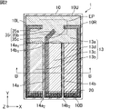
- FIG. 1 is a perspective view schematically showing an example of a vapor chamber, which is a heat diffusion device according to a first embodiment of the invention.
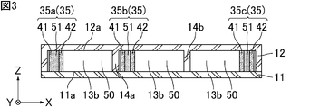
- FIG. 2 is a cross-sectional view taken along line AA of FIG. 3 is a cross-sectional view taken along line BB of FIG. 2.
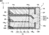
- FIG. 4 is a cross-sectional view schematically showing an example in which the vapor chamber shown in FIG. 1 is used with the right side surface of the housing positioned vertically downward.
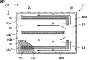
- FIG. 5 is a cross-sectional view schematically showing an example in which a conventional vapor chamber is used with the right side surface of the housing positioned vertically downward.
- FIG. 1 is a perspective view schematically showing an example of a vapor chamber, which is a heat diffusion device according to a first embodiment of the invention.
- FIG. 2 is a cross-sectional view taken along line AA of FIG. 3 is a cross-sectional view taken along line BB of FIG. 2.
- FIG. 4 is a cross-sectional view
- FIG. 6 is a cross-sectional view schematically showing an example of a vapor chamber, which is a heat diffusion device according to the second embodiment of the present invention.
- FIG. 7 is a cross-sectional view schematically showing an example of the internal structure of a conventional vapor chamber having an L-shaped housing.
- FIG. 8 is a cross-sectional view schematically showing an example in which the vapor chamber, which is the heat diffusion device according to the second embodiment of the present invention, is used with the right side surface of the housing positioned downward in the vertical direction.
- FIG. 9 is a cross-sectional view schematically showing an example in which a conventional vapor chamber having an L-shaped housing is used with the right side of the housing positioned vertically downward.
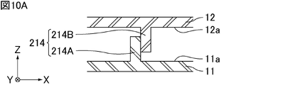
- FIG. 10A is a cross-sectional view schematically showing an example of a partition wall of a vapor chamber, which is a heat diffusion device according to the present invention.
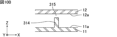
- FIG. 10B is a cross-sectional view schematically showing an example of a partition wall of the vapor chamber, which is the heat diffusion device according to the present invention.
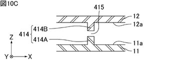
- FIG. 10C is a cross-sectional view schematically showing an example of the partition wall of the vapor chamber, which is the heat diffusion device according to the present invention.
- FIG. 10D is a cross-sectional view schematically showing an example of the partition wall of the vapor chamber, which is the heat diffusion device according to the present invention.
- the heat diffusion device of the present invention will be described below.
- the present invention is not limited to the following configurations, and can be appropriately modified and applied without changing the gist of the present invention. It should be noted that a combination of two or more of the individual preferred configurations of the invention described below is also the invention.
- a heat diffusion device of the present invention comprises a housing having an internal space and comprising a first inner wall surface and a second inner wall surface facing each other in a thickness direction, a working medium enclosed in the internal space, and a first wick and a second wick arranged; and an impermeable partition wall having a first end and a second end arranged in the interior space, wherein the first wick and the second wick each has a portion in contact with the first inner wall surface and the second inner wall surface of the housing along a direction perpendicular to the thickness direction, and a steam flow path is provided in the internal space of the housing.
- a second end portion of the partition wall is connected to an inner surface of the housing, and when the internal space is viewed from the thickness direction, the partition wall is formed in the direction of the first wick. and the second wick.
- FIG. 1 is a perspective view schematically showing an example of a vapor chamber, which is a heat diffusion device according to a first embodiment of the invention.
- the vapor chamber 1 shown in FIG. 1 includes a hollow housing 10 that is hermetically sealed.
- a heat source HS which is a heating element, is arranged on the outer wall surface of the housing 10 .
- the heat source HS include electronic components of electronic equipment, such as a central processing unit (CPU).
- the vapor chamber 1 is planar as a whole. That is, the housing 10 is planar as a whole.
- the “planar shape” includes a plate shape and a sheet shape, and the dimension in the width direction X (hereinafter referred to as width) and the dimension in the length direction Y (hereinafter referred to as length) are the thickness direction Z
- width width
- length dimension in the length direction
- Z It means a shape that is considerably large with respect to its dimensions (hereafter referred to as thickness or height). For example, it means a shape whose width and length are 10 times or more, preferably 100 times or more, the thickness.
- the size of the vapor chamber 1, that is, the size of the housing 10 is not particularly limited.
- the width and length of the vapor chamber 1 can be appropriately set according to the application.
- the width and length of the vapor chamber 1 are, for example, 5 mm or more and 500 mm or less, 20 mm or more and 300 mm or less, or 50 mm or more and 200 mm or less.
- the width and length of the vapor chamber 1 may be the same or different.
- the width and length of the vapor chamber are defined as the maximum values in the width and length directions.
- the housing 10 is preferably composed of a first sheet 11 and a second sheet 12 that face each other and whose outer edges are joined.
- Materials for the first sheet 11 and the second sheet 12 are not particularly limited as long as they have properties suitable for use as a vapor chamber, such as thermal conductivity, strength, softness, and flexibility.
- the material that constitutes the first sheet 11 and the second sheet 12 is preferably a metal, such as copper, nickel, aluminum, magnesium, titanium, iron, or an alloy containing them as a main component, and copper is particularly preferable. is.
- the materials forming the first sheet 11 and the second sheet 12 may be the same or different, but are preferably the same.
- the housing 10 is composed of the first sheet 11 and the second sheet 12
- the first sheet 11 and the second sheet 12 are joined together at their outer edges.
- Such bonding methods are not particularly limited, but laser welding, resistance welding, diffusion bonding, brazing, TIG welding (tungsten-inert gas welding), ultrasonic bonding, or resin sealing can be used, for example.
- TIG welding tungsten-inert gas welding
- ultrasonic bonding or resin sealing
- resin sealing for example.
- laser welding, resistance welding or brazing can be used.
- the thicknesses of the first sheet 11 and the second sheet 12 are not particularly limited, but each is preferably 10 ⁇ m or more and 200 ⁇ m or less, more preferably 30 ⁇ m or more and 100 ⁇ m or less, still more preferably 40 ⁇ m or more and 60 ⁇ m or less.
- the thicknesses of the first sheet 11 and the second sheet 12 may be the same or different. Also, the thickness of each sheet of the first sheet 11 and the second sheet 12 may be the same over the entire area, or may be thin in part.
- first sheet 11 and the second sheet 12 are not particularly limited.
- first sheet 11 may have a flat plate shape with a constant thickness
- second sheet 12 may have a shape in which the outer edge portion is thicker than the portions other than the outer edge portion.
- the first sheet 11 may have a flat plate shape with a constant thickness
- the second sheet 12 may have a constant thickness and a portion other than the outer edge with respect to the outer edge may be convex outward. good.
- a recess is formed in the outer edge of the housing 10 . Therefore, the concave portion of the outer edge can be used when mounting the vapor chamber. Also, other components can be placed in the recesses of the outer edge.
- the thickness of the entire vapor chamber 1 is not particularly limited, it is preferably 50 ⁇ m or more and 500 ⁇ m or less.
- the planar shape of the housing 10 viewed from the thickness direction Z is a rectangular shape with the length direction Y being the longitudinal direction.
- the shape of the housing is not particularly limited, and may be, for example, L-shaped, C-shaped (U-shaped), step-shaped, or the like. Further, the housing may have a space (through-hole) inside the planar figure.
- the planar shape of the housing may be a shape according to the use of the vapor chamber, the shape of the location where the vapor chamber is installed, and other parts existing nearby.
- FIG. 2 is a cross-sectional view taken along line AA of FIG. 3 is a cross-sectional view taken along line BB of FIG. 2.
- FIG. 2 is a cross-sectional view taken along line AA of FIG. 3 is a cross-sectional view taken along line BB of FIG. 2.
- the housing 10 of the vapor chamber 1 has an internal space 13 and includes a first inner wall surface 11a and a second inner wall surface 12a facing each other in the thickness direction Z.
- the upper surface of the housing 10 in FIG. The posture of the vapor chamber 1 of the present invention during use is not particularly limited, and the upper surface 10U does not have to be vertically upward.
- the upper surface 10U, the left side 10L, the right side 10R, and the bottom 10B are all inner side surfaces of the housing 10 that form the internal space 13. As shown in FIG.
- the internal space 13 contains a working medium 20 .
- the working medium 20 is not particularly limited as long as it can cause a gas-liquid phase change in the environment inside the housing 10.
- water, alcohols, CFC alternatives, and the like can be used.
- the working medium is an aqueous compound, preferably water.
- the first region 13a of the housing 10 is provided with an evaporation portion EP for evaporating the enclosed working medium 20.
- an evaporation portion EP for evaporating the enclosed working medium 20.
- a portion of the internal space 13 of the housing 10 that is in the vicinity of the heat source HS and is heated by the heat source HS corresponds to the evaporating portion EP.
- the internal space 13 includes at least a first area 13a, a second area 13b, a third area 13c and a fourth area 13d.
- the first region 13a and the second region 13b are adjacent to each other so as to be continuous.
- the first region 13a and the third region 13c are adjacent to each other so as to be continuous.
- the first area 13a and the fourth area 13d are adjacent to each other so as to be continuous.
- the second region 13b and the third region 13c are adjacent to each other with an impermeable first partition wall 14a interposed therebetween.
- the third area 13c and the fourth area 13d are adjacent to each other with the air-impermeable second partition wall 14b interposed therebetween.
- the first partition wall 14a has a first end 14a 1 and a second end 14a 2 , the first end 14a 1 is in contact with the first region 13a, and the second end 14a 2 is a bottom surface. 10B is connected.
- the second partition wall 14b has a first end 14b_1 and a second end 14b_2, the first end 14b_1 is in contact with the first region 13a, and the second end 14b_2 is a bottom surface. 10B is connected.
- the second area 13b is an area surrounded by the left side surface 10L, the bottom surface 10B, and the first partition wall 14a.
- the first area 13a and the second area 13b are distinguished by a boundary connecting the shortest distance between the left side surface 10L and the first end 14a1 of the first partition wall 14a.
- a third area 13c is an area surrounded by the first partition wall 14a, the bottom surface 10B, and the second partition wall 14b.
- the first region 13a and the third region 13c are distinguished by a boundary connecting the first end 14a1 of the first partition wall 14a and the first end 14b1 of the second partition wall 14b.
- the fourth area 13d is an area surrounded by the second partition wall 14b, the bottom surface 10B and the right side surface 10R.
- the first area 13a and the fourth area 13d are distinguished by a boundary connecting the shortest distance between the first end 14b1 of the second partition wall 14b and the right side surface 10R. Also, the first area 13a is an area surrounded by the left side 10L, the upper surface 10U, and the right side 10R. The boundaries between the first area 13a, the second area 13b, the third area 13c and the fourth area 13d are as described above.
- the first end 14a1 of the first partition wall 14a and the first end 14b1 of the second partition wall 14b are formed apart from the vaporization section EP, but the vapor chamber of the present invention is not limited to this.
- the first end of each partition wall may be arranged so as to be in contact with the evaporator.
- the first partition wall 14a and the second partition wall 14b are formed continuously in the thickness direction Z from the first inner wall surface 10a to the second inner wall surface 12a.
- the width of the first partition wall 14a and the second partition wall 14b (the width in the width direction X in FIG. 3) is preferably 200 ⁇ m or more and 1000 ⁇ m or less, more preferably 500 ⁇ m or more and 600 ⁇ m or less.
- the first partition wall 14a and the second partition wall 14b are not particularly limited as long as they are air-impermeable. is preferred. Moreover, the first partition wall 14 a and the second partition wall 14 b are preferably made of the same material as the first sheet 11 and the second sheet 12 . The materials forming the first partition wall 14a and the second partition wall 14b may be the same or different, but are preferably the same. Further, the materials of the first partition wall 14a and the second partition wall 14b and the materials of the first sheet 11 and the second sheet 12 may be the same or different.
- the first partition wall 14a and the second partition wall 14b are formed by laser welding, resistance welding, diffusion bonding, brazing, TIG welding (tungsten-inert gas welding), ultrasonic bonding, or resin bonding of plate materials. good too.
- the first partition wall 14a and the second partition wall 14b may be formed by etching the first sheet 11 and the second sheet 12, respectively.
- the first partition wall 14a and the second partition wall 14b may be formed by printing a sintered metal and sintering it.
- a wick 35 is arranged in the internal space 13 .
- the wick 35 includes a first wick 35a formed from the first region 13a to the second region 13b, a second wick 35b formed from the first region 13a to the third region 13c, and a fourth region from the first region 13a to the fourth region. and a third wick 35c formed over 13d.
- the first wick 35a is formed along the bottom surface 10B and the left side surface 10L of the second region 13b.
- the second wick 35b is formed along the bottom surface 10B of the third region 13c and the first partition wall 14a.
- the third wick 35c is formed along the bottom surface 10B and right side surface 10R of the fourth region 13d.
- the wicks 35 are arranged such that one end of each of the first wick 35a, the second wick 35b and the third wick 35c reaches the evaporator EP.
- a region around the other end of each of the first wick 35a, the second wick 35b, and the third wick 35c is located away from the evaporator EP and serves as a condensing portion for condensing the evaporated working medium.
- the first wick 35a, the second wick 35b, and the third wick 35c extend along the direction perpendicular to the thickness direction Z, along the first inner wall surface 11a and the second inner wall surface 12a of the housing 10. It has a portion that touches the inside.
- Each wick 35 includes a first porous body 41 and a second porous body 42 .
- These porous bodies have the function of transporting the working medium 20 by capillary force.
- the first porous body 41 and the second porous body 42 that constitute each wick 35 have portions in contact with the first inner wall surface 11a and the second inner wall surface 12a of the housing 10, respectively.
- the thickness of the first porous body 41 and the second porous body 42 forming each wick 35 is substantially the same as the thickness of the internal space 13 of the housing 10 .
- the first porous body 41 and the second porous body 42 for example, metal porous films, meshes, non-woven fabrics, sintered bodies, and other porous bodies formed by etching or metal working are used.
- the mesh that is the material of the wick may be composed of, for example, a metal mesh, a resin mesh, or a surface-coated mesh thereof, preferably a copper mesh, a stainless steel (SUS) mesh, or a polyester mesh.
- the sintered body that is the material of the wick may be composed of, for example, a metal porous sintered body or a ceramic porous sintered body, preferably a porous sintered body of copper or nickel.
- Other porous bodies used as wick materials may be composed of, for example, metal porous bodies, ceramic porous bodies, resin porous bodies, or the like.
- a mesh, a nonwoven fabric, and a sintered body are also included in the porous body in this specification.
- each wick 35 a space is provided between the first porous body 41 and the second porous body 42 along the direction in which the first porous body 41 and the second porous body 42 extend.
- a liquid pool flow path 51 is formed.
- the liquid pool channel 51 can be used as a liquid channel through which the liquid-phase working medium 20 flows.
- FIG. 4 is a cross-sectional view schematically showing an example in which the vapor chamber shown in FIG. 1 is used with the right side surface of the housing positioned vertically downward.
- the connecting portion between the bottom surface 10B and the first partition wall 14a, the bottom surface 10B and the The liquid-phase working medium 20 tends to accumulate in the connection portion with the partition wall 14b and the connection portion of the right side surface 10R.
- Such a liquid-phase working medium 20 is quickly recovered by the first wick 35a, the second wick 35b, and the third wick 35c. That is, in the vapor chamber 1, the liquid-phase working medium 20 is concentrated in one place and is difficult to accumulate. Therefore, the in-plane temperature uniformity of the vapor chamber 1 is maintained, and it is possible to prevent a decrease in the maximum heat transport amount.
- the gas-phase working medium 20 moves substantially evenly to the second area 13b, the third area 13c, and the fourth area 13d, although it is affected by gravity. Since the first partition wall 14a and the second partition wall 14b are impermeable, the gas-phase working medium 20 cannot move between the second region 13b and the third region 13c through the first partition wall 14a. The third area 13c and the fourth area 13d cannot be moved through 14b. Therefore, it is possible to prevent the working medium 20 from biasing toward any one of the second region 13b, the third region 13c, and the fourth region 13d. That is, the fact that the first partition wall 14 a and the second partition wall 14 b are impermeable also contributes to maintaining the in-plane temperature uniformity of the vapor chamber 1 .
- the first partition wall 14a and the second partition wall 14b are preferably hydrophobic.
- water is less likely to adhere to the first partition wall 14a and the second partition wall 14b.
- water becomes a liquid phase, the water quickly moves along the first partition wall 14a and the second partition wall 14b, and is easily collected by each wick.
- one first wick 35a, one second wick 35b and one third wick 35c are arranged in the second region 13b, the third region 13c and the fourth region 13d, respectively.
- a plurality of wicks may be arranged in each region in the vapor chamber according to the first embodiment of the present invention. By arranging a plurality of wicks, the recovery efficiency of the working medium is improved.
- the preferred ratio of the wick to the internal space is as follows.
- the ratio of the area of the first wick 35a to the area of the second region 13b is preferably 60% or less, and preferably 30% or less. is more preferred.
- the ratio of the area of the second wick 35b to the area of the third region 13c is preferably 60% or less, preferably 30% or less. is more preferred.
- the ratio of the area of the third wick 35c to the area of the fourth region 13d is preferably 60% or less, preferably 30% or less. is more preferred.
- FIG. 5 is a cross-sectional view schematically showing an example in which a conventional vapor chamber is used with the right side surface of the housing positioned vertically downward.
- the vapor chamber 1' shown in FIG. 5 is not formed with the first partition wall 14a and the second partition wall 14b, and instead of the first wick 35a, the second wick 35b and the third wick 35c, the first wick 35a ', a second wick 35b', and a third wick 35c'.
- the first wick 35a', the second wick 35b', and the third wick 35c' are formed to extend from the evaporator EP to the vicinity of the bottom surface 10B.
- a steam flow path 50 is formed between the right side surface 10R.
- the liquid-phase working medium 20 is biased toward the connecting portion between the bottom surface 10B and the right side surface 10R to form a pool. If such a pool is uneven, the working medium 20 can be recovered by the third wick 35c', but the working medium 20 cannot be recovered by the first wick 35a' and the second wick 35b'. Since the temperature around the liquid pool is low, the in-plane temperature uniformity of the vapor chamber 1' is uneven. In such a case, the maximum heat transfer amount of the vapor chamber 1' is reduced.
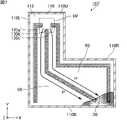
- FIG. 6 is a cross-sectional view schematically showing an example of a vapor chamber, which is a heat diffusion device according to the second embodiment of the present invention.
- the planar shape of the housing 110 viewed from the thickness direction Z is L-shaped.
- the upper surface of housing 110 in FIG. The housing 110 has a right side surface 110R formed in a crank shape.
- the posture of the vapor chamber 101 of the present invention during use is not particularly limited, and the upper surface 110U does not have to be vertically upward. Further, the upper surface 110U, the left side 110L, the right side 110R, and the bottom 110B are all inner side surfaces of the housing 110 that form the internal space 113. As shown in FIG.
- the internal space 113 includes at least a first area 113a, a second area 113b, a third area 113c and a fourth area 113d.
- the first region 113a and the second region 113b are adjacent to each other so as to be continuous.
- the first region 113a and the third region 113c are adjacent to each other so as to be continuous.
- the first region 113a and the fourth region 113d are adjacent to each other so as to be continuous.
- the second area 113b and the third area 113c are adjacent to each other with the air-impermeable first partition wall 114a interposed therebetween.
- the third area 113c and the fourth area 113d are adjacent to each other with the air-impermeable second partition wall 114b interposed therebetween.
- the first partition wall 114a has a first end 114a1 and a second end 114a2, the first end 114a1 is in contact with the first region 113a, and the second end 114a2 is the bottom surface. 110B.
- the second partition wall 114b has a first end 114b1 and a second end 114b2, the first end 114b1 is in contact with the first region 113a, and the second end 114b2 is the bottom surface. 110B.
- the second area 113b is an area surrounded by the left side 110L, the bottom 110B, and the first partition wall 114a.
- the first area 113a and the second area 113b are distinguished by a boundary connecting the shortest distance between the left side surface 110L and the first end 114a1 of the first partition wall 114a.
- a third area 113c is an area surrounded by the first partition wall 114a, the bottom surface 110B, and the second partition wall 114b.
- the first region 113a and the third region 13c are distinguished by a boundary connecting the first end 114a1 of the first partition wall 114a and the first end 114b1 of the second partition wall 114b.
- the fourth area 113d is an area surrounded by the second partition wall 114b, the bottom surface 110B, and the right side surface 110R.
- the first area 113a and the fourth area 113d are distinguished by a boundary connecting the shortest distance between the first end 114b1 of the second partition wall 114b and the right side surface 110R.
- the first area 113a is an area surrounded by the left side 110L, the upper surface 110U, and the right side 110R.
- the boundaries between the first region 113a, the second region 113b, the third region 113c, and the fourth region 113d are as described above.
- the first partition wall 114a and the second partition wall 114b allow the liquid-phase working medium 20 to move to the first region 113a by gravity when the vapor chamber 101 is positioned such that the upper surface 110U is vertically downward. It is bent like That is, the first partition wall 114a and the second partition wall 114b are bent from the bottom surface 110B toward the evaporator EP.
- a wick 135 is arranged in the internal space 113 .
- the wick 135 includes a first wick 135a formed from the first region 113a to the second region 113b, a second wick 135b formed from the first region 113a to the third region 113c, and a fourth region from the first region 113a. and a third wick 135c formed over 113d.
- the first wick 135a is formed along the bottom surface 110B, left side surface 110L, and part of the first partition wall 114a of the second region 113b.
- the second wick 135b is formed along part of the bottom surface 110B of the third region 113c, the first partition wall 114a and the second partition wall 114b.
- the third wick 135c is formed along the bottom surface 110B and right side surface 110R of the fourth region 113d.
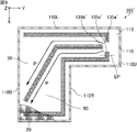
- the vapor chamber 101 shown in FIG. 6 has the first partition wall 114a and the second partition wall 114b, it is difficult for the liquid to pool in one place. Further, the liquid-phase working medium 20 generated in the second region 113b, the third region 113c, and the fourth region 113d are quickly collected by the first wick 135a, the second wick 135b, and the third wick 135c, respectively. Therefore, the in-plane temperature uniformity of the vapor chamber 1 is maintained, and it is possible to prevent a decrease in the maximum heat transport amount.
- FIG. 7 is a cross-sectional view schematically showing an example of the internal structure of a conventional vapor chamber having an L-shaped housing.
- the vapor chamber 101′ shown in FIG. 7 is not formed with the first partition wall 114a and the second partition wall 114b, and instead of the first wick 135a, the second wick 135b and the third wick 135c, the first wick 135a ', a second wick 135b', and a third wick 135c'.
- the first wick 135a' is formed to extend from the evaporator EP to the vicinity of the bottom surface 110B.
- the second wick 135b' extends from the evaporating portion EP toward the bottom surface 110B, bends in the middle, and extends to the vicinity of the connection portion between the bottom surface 110B and the right side surface 110R.
- the third wick 135c' is formed in a crank shape along the right side surface 110R. Steam flow paths 50 are formed between the first wick 135a' and the second wick 135b' and between the second wick 135b' and the third wick 135c'.
- the liquid-phase working medium 20 is biased toward the connecting portion between the bottom surface 110B and the right side surface 110R to form a pool. If such a pool is uneven, the working medium 20 can be recovered by the second wick 135b' and the third wick 135c', but the working medium 20 cannot be recovered by the first wick 135a'. Since the temperature around the liquid pool is low, the in-plane temperature uniformity of the vapor chamber 101' is uneven. In such a case, the maximum heat transfer amount of the vapor chamber 101' is reduced.
- FIG. 8 is a cross-sectional view schematically showing an example in which the vapor chamber, which is the heat diffusion device according to the second embodiment of the present invention, is used with the right side surface of the housing positioned downward in the vertical direction.
- FIG. 9 is a cross-sectional view schematically showing an example in which a conventional vapor chamber having an L-shaped housing is used with the right side of the housing positioned vertically downward.
- the partition wall is formed as an integral wall, and is continuously formed in the thickness direction from the first inner wall surface to the second inner wall surface. It had been.
- the partition wall may be formed of two walls, a wall formed on the first inner wall surface and a wall formed on the second inner wall surface.
- the partition wall is formed from the first inner wall surface to the second inner wall surface in the thickness direction, and the partition wall extends from the first inner wall surface to the second inner wall surface. You may have a discontinuous area between to a wall surface.
- 10A to 10D are cross-sectional views schematically showing examples of partition walls of the vapor chamber, which is the heat diffusion device of the present invention.
- the partition wall 214 shown in FIG. 10A includes a partition wall 214A formed from the first inner wall surface 11a to the second inner wall surface 12a in the thickness direction Z, and a partition wall 214A formed in the thickness direction Z from the second inner wall surface 12a to the first inner wall surface 11a. and a partition wall 214B formed over The formation position of the partition wall 214A and the formation position of the partition wall 214B are displaced from each other in the width direction X, and the partition wall 214A and the partition wall 214B are in contact with each other.
- the partition wall 314 shown in FIG. 10B is formed from the first inner wall surface 11a to the second inner wall surface 12a in the thickness direction Z, and between the end of the partition wall 314 and the second inner wall surface 12a, A discontinuous region 315 is formed.
- the partition wall 414 shown in FIG. 10C includes a partition wall 414A formed from the first inner wall surface 11a to the second inner wall surface 12a in the thickness direction Z, and a partition wall 414A formed in the thickness direction Z from the second inner wall surface 12a to the first inner wall surface 11a. and a partition wall 414B formed over.
- a discontinuous region 415 is formed between the end of the partition wall 414A and the end of the partition wall 414B.
- the formation position of the partition wall 414A and the formation position of the partition wall 414B in the width direction X are the same.
- the partition wall 514 shown in FIG. 10D includes a partition wall 514A formed from the first inner wall surface 11a to the second inner wall surface 12a in the thickness direction Z, and a partition wall 514A formed in the thickness direction Z from the second inner wall surface 12a to the first inner wall surface 11a. and a partition wall 514B formed over The formation position of the partition wall 514A and the formation position of the partition wall 514B in the width direction X are displaced.
- a discontinuous region 515 is formed between the partition wall 514A and the partition wall 514B.
- the partition wall has the effect of preventing the working medium from accumulating in one place. Therefore, even in such a vapor chamber, the maximum heat transfer rate is unlikely to decrease.
- the internal space of the housing is divided into the first region, the second region and the third region. and a fourth region.
- the internal space of the housing may be formed only from the first area, the second area and the third area.
- the internal space of the housing may further include other regions.
- the other area is adjacent to the first area so as to be continuous, and is further adjacent to another area with a partition wall interposed therebetween. Also, in such another region, a wick is formed from the first region to the other region.
- the vapor chamber which is the heat diffusion device of the present invention, can be mounted on electronic equipment for the purpose of heat dissipation. Therefore, it can be used as an electronic device comprising a vapor chamber, which is the heat diffusion device of the present invention, and an electronic component attached to the outer wall surface of a housing that constitutes the vapor chamber.
- the vapor chamber which is the heat diffusion device of the present invention, operates independently without the need for external power, and utilizes the latent heat of vaporization and latent heat of condensation of the working medium to diffuse heat two-dimensionally at high speed. be able to. Therefore, an electronic device having a vapor chamber, which is the heat diffusion device of the present invention, can effectively dissipate heat in a limited space inside the electronic device.
- the electronic component corresponds to the heat source HS shown in FIG.
- Examples of electronic devices include smartphones, tablet terminals, laptops, game machines, and wearable devices.
- Electronic parts that are objects to be cooled include, for example, heat generating elements such as central processing units (CPUs), light emitting diodes (LEDs), and power semiconductors.
- the electronic components may be attached directly to the outer wall surface of the housing, or may be attached via other members such as adhesives, sheets, and tapes with high thermal conductivity.
- the vapor chamber which is the heat diffusion device of the present invention, can be used for a wide range of applications in fields such as personal digital assistants. For example, it can be used to lower the temperature of a heat source such as a CPU and extend the operating time of electronic equipment, and can be used in smartphones, tablet terminals, laptop computers, and the like.
Landscapes
- Engineering & Computer Science (AREA)
- Physics & Mathematics (AREA)
- Thermal Sciences (AREA)
- Mechanical Engineering (AREA)
- General Engineering & Computer Science (AREA)
- Life Sciences & Earth Sciences (AREA)
- Sustainable Development (AREA)
- Cooling Or The Like Of Semiconductors Or Solid State Devices (AREA)
- Cooling Or The Like Of Electrical Apparatus (AREA)
Priority Applications (3)
| Application Number | Priority Date | Filing Date | Title |
|---|---|---|---|
| JP2023527531A JP7464197B2 (ja) | 2021-06-07 | 2022-03-28 | 熱拡散デバイス |
| CN202290000378.XU CN221527444U (zh) | 2021-06-07 | 2022-03-28 | 热扩散器件 |
| US18/465,201 US12529525B2 (en) | 2021-06-07 | 2023-09-12 | Heat diffusion device |
Applications Claiming Priority (2)
| Application Number | Priority Date | Filing Date | Title |
|---|---|---|---|
| JP2021095017 | 2021-06-07 | ||
| JP2021-095017 | 2021-06-07 |
Related Child Applications (1)
| Application Number | Title | Priority Date | Filing Date |
|---|---|---|---|
| US18/465,201 Continuation US12529525B2 (en) | 2021-06-07 | 2023-09-12 | Heat diffusion device |
Publications (1)
| Publication Number | Publication Date |
|---|---|
| WO2022259716A1 true WO2022259716A1 (ja) | 2022-12-15 |
Family
ID=84425222
Family Applications (1)
| Application Number | Title | Priority Date | Filing Date |
|---|---|---|---|
| PCT/JP2022/014906 Ceased WO2022259716A1 (ja) | 2021-06-07 | 2022-03-28 | 熱拡散デバイス |
Country Status (4)
| Country | Link |
|---|---|
| US (1) | US12529525B2 (cg-RX-API-DMAC7.html) |
| JP (1) | JP7464197B2 (cg-RX-API-DMAC7.html) |
| CN (1) | CN221527444U (cg-RX-API-DMAC7.html) |
| WO (1) | WO2022259716A1 (cg-RX-API-DMAC7.html) |
Cited By (1)
| Publication number | Priority date | Publication date | Assignee | Title |
|---|---|---|---|---|
| US20250321061A1 (en) * | 2022-07-15 | 2025-10-16 | Barry Richard Brooks | Modular thermal energy storage and transfer in a pcm hosting system |
Citations (6)
| Publication number | Priority date | Publication date | Assignee | Title |
|---|---|---|---|---|
| JPS6383587A (ja) * | 1986-09-29 | 1988-04-14 | Toshiba Corp | 平板形ヒ−トパイプ |
| JP2002267378A (ja) * | 2001-03-12 | 2002-09-18 | Showa Denko Kk | ヒートパイプ |
| JP2011102691A (ja) * | 2009-11-10 | 2011-05-26 | Pegatron Corp | ベーパーチャンバー及びその製造方法 |
| JP2018185110A (ja) * | 2017-04-26 | 2018-11-22 | 株式会社フジクラ | ヒートパイプ |
| JP2019113270A (ja) * | 2017-12-25 | 2019-07-11 | 株式会社フジクラ | 放熱モジュール |
| JP2020106209A (ja) * | 2018-12-27 | 2020-07-09 | 川崎重工業株式会社 | 蒸発器及びループ型ヒートパイプ |
Family Cites Families (11)
| Publication number | Priority date | Publication date | Assignee | Title |
|---|---|---|---|---|
| JPS5835948A (ja) * | 1981-08-28 | 1983-03-02 | Fujitsu Ltd | 液冷モジユ−ル |
| JPS59124874U (ja) * | 1983-02-07 | 1984-08-22 | 株式会社アマダ | 平板状ヒ−トパイプ |
| JP3506050B2 (ja) * | 1999-03-26 | 2004-03-15 | トヨタ自動車株式会社 | 発熱素子の冷却装置 |
| JP2002062066A (ja) * | 2000-08-11 | 2002-02-28 | Furukawa Electric Co Ltd:The | ヒートパイプ |
| JP2006114603A (ja) * | 2004-10-13 | 2006-04-27 | Toshiba Corp | 車両用半導体冷却装置 |
| JP2008051407A (ja) * | 2006-08-24 | 2008-03-06 | Toshiba Corp | ヒートパイプ、冷却装置、電子機器 |
| US11454454B2 (en) * | 2012-03-12 | 2022-09-27 | Cooler Master Co., Ltd. | Flat heat pipe structure |
| TWM532046U (zh) * | 2016-06-02 | 2016-11-11 | 泰碩電子股份有限公司 | 具有液汽分離結構的均溫板 |
| WO2018116951A1 (ja) * | 2016-12-20 | 2018-06-28 | 株式会社フジクラ | 放熱モジュール |
| US20180372424A1 (en) * | 2017-06-21 | 2018-12-27 | Microsoft Technology Licensing, Llc | Vapor chamber that emits a non-uniform radiative heat flux |
| TWM562956U (zh) * | 2017-10-12 | 2018-07-01 | 泰碩電子股份有限公司 | 內凸紋構成流道之均溫板 |
-
2022
- 2022-03-28 WO PCT/JP2022/014906 patent/WO2022259716A1/ja not_active Ceased
- 2022-03-28 JP JP2023527531A patent/JP7464197B2/ja active Active
- 2022-03-28 CN CN202290000378.XU patent/CN221527444U/zh active Active
-
2023
- 2023-09-12 US US18/465,201 patent/US12529525B2/en active Active
Patent Citations (6)
| Publication number | Priority date | Publication date | Assignee | Title |
|---|---|---|---|---|
| JPS6383587A (ja) * | 1986-09-29 | 1988-04-14 | Toshiba Corp | 平板形ヒ−トパイプ |
| JP2002267378A (ja) * | 2001-03-12 | 2002-09-18 | Showa Denko Kk | ヒートパイプ |
| JP2011102691A (ja) * | 2009-11-10 | 2011-05-26 | Pegatron Corp | ベーパーチャンバー及びその製造方法 |
| JP2018185110A (ja) * | 2017-04-26 | 2018-11-22 | 株式会社フジクラ | ヒートパイプ |
| JP2019113270A (ja) * | 2017-12-25 | 2019-07-11 | 株式会社フジクラ | 放熱モジュール |
| JP2020106209A (ja) * | 2018-12-27 | 2020-07-09 | 川崎重工業株式会社 | 蒸発器及びループ型ヒートパイプ |
Cited By (2)
| Publication number | Priority date | Publication date | Assignee | Title |
|---|---|---|---|---|
| US20250321061A1 (en) * | 2022-07-15 | 2025-10-16 | Barry Richard Brooks | Modular thermal energy storage and transfer in a pcm hosting system |
| US12624902B2 (en) * | 2022-07-15 | 2026-05-12 | Barry Richard Brooks | Modular thermal energy storage and transfer in a PCM hosting system |
Also Published As
| Publication number | Publication date |
|---|---|
| US12529525B2 (en) | 2026-01-20 |
| US20240011717A1 (en) | 2024-01-11 |
| CN221527444U (zh) | 2024-08-13 |
| JPWO2022259716A1 (cg-RX-API-DMAC7.html) | 2022-12-15 |
| JP7464197B2 (ja) | 2024-04-09 |
Similar Documents
| Publication | Publication Date | Title |
|---|---|---|
| US11445636B2 (en) | Vapor chamber, heatsink device, and electronic device | |
| JP6442594B1 (ja) | 放熱モジュール | |
| JP7111266B2 (ja) | ベーパーチャンバー | |
| US20210180876A1 (en) | Vapor chamber | |
| WO2023090265A1 (ja) | 熱拡散デバイス | |
| JP7464197B2 (ja) | 熱拡散デバイス | |
| US20230122387A1 (en) | Vapor chamber with unequal cross-sectional widths | |
| JP7120494B1 (ja) | 熱拡散デバイス | |
| WO2023021953A1 (ja) | 熱拡散デバイス及び電子機器 | |
| JP7260062B2 (ja) | 熱拡散デバイス | |
| JP7244375B2 (ja) | ベーパーチャンバー | |
| CN222638937U (zh) | 热扩散器件以及电子设备 | |
| JP7283641B2 (ja) | 熱拡散デバイス | |
| JP2018189320A (ja) | ヒートパイプ及び電子機器 | |
| WO2022230357A1 (ja) | 熱拡散デバイス | |
| WO2023182029A1 (ja) | 熱拡散デバイス及び電子機器 | |
| WO2023171408A1 (ja) | 熱拡散デバイス及び電子機器 | |
| WO2023182033A1 (ja) | 熱拡散デバイス及び電子機器 | |
| JP7311057B2 (ja) | 熱拡散デバイスおよび電子機器 | |
| WO2022230295A1 (ja) | 熱拡散デバイス | |
| JP7222448B2 (ja) | 熱拡散デバイス | |
| WO2023058595A1 (ja) | 熱拡散デバイス | |
| WO2023085350A1 (ja) | 熱拡散デバイス | |
| WO2022230296A1 (ja) | 熱拡散デバイス | |
| WO2023026896A1 (ja) | 熱拡散デバイス |
Legal Events
| Date | Code | Title | Description |
|---|---|---|---|
| 121 | Ep: the epo has been informed by wipo that ep was designated in this application |
Ref document number: 22819905 Country of ref document: EP Kind code of ref document: A1 |
|
| WWE | Wipo information: entry into national phase |
Ref document number: 202290000378.X Country of ref document: CN |
|
| WWE | Wipo information: entry into national phase |
Ref document number: 2023527531 Country of ref document: JP |
|
| NENP | Non-entry into the national phase |
Ref country code: DE |
|
| 122 | Ep: pct application non-entry in european phase |
Ref document number: 22819905 Country of ref document: EP Kind code of ref document: A1 |