WO2022239794A1 - 構造部材 - Google Patents
構造部材 Download PDFInfo
- Publication number
- WO2022239794A1 WO2022239794A1 PCT/JP2022/019907 JP2022019907W WO2022239794A1 WO 2022239794 A1 WO2022239794 A1 WO 2022239794A1 JP 2022019907 W JP2022019907 W JP 2022019907W WO 2022239794 A1 WO2022239794 A1 WO 2022239794A1
- Authority
- WO
- WIPO (PCT)
- Prior art keywords
- section
- closed cross
- structural member
- cross
- axis direction
- Prior art date
- Legal status (The legal status is an assumption and is not a legal conclusion. Google has not performed a legal analysis and makes no representation as to the accuracy of the status listed.)
- Ceased
Links
Images






Classifications
-
- B—PERFORMING OPERATIONS; TRANSPORTING
- B60—VEHICLES IN GENERAL
- B60G—VEHICLE SUSPENSION ARRANGEMENTS
- B60G7/00—Pivoted suspension arms; Accessories thereof
- B60G7/001—Suspension arms, e.g. constructional features
-
- B—PERFORMING OPERATIONS; TRANSPORTING
- B60—VEHICLES IN GENERAL
- B60G—VEHICLE SUSPENSION ARRANGEMENTS
- B60G2206/00—Indexing codes related to the manufacturing of suspensions: constructional features, the materials used, procedures or tools
- B60G2206/01—Constructional features of suspension elements, e.g. arms, dampers, springs
- B60G2206/012—Hollow or tubular elements
-
- B—PERFORMING OPERATIONS; TRANSPORTING
- B60—VEHICLES IN GENERAL
- B60G—VEHICLE SUSPENSION ARRANGEMENTS
- B60G2206/00—Indexing codes related to the manufacturing of suspensions: constructional features, the materials used, procedures or tools
- B60G2206/01—Constructional features of suspension elements, e.g. arms, dampers, springs
- B60G2206/10—Constructional features of arms
- B60G2206/122—Constructional features of arms the arm having L-shape
-
- B—PERFORMING OPERATIONS; TRANSPORTING
- B60—VEHICLES IN GENERAL
- B60G—VEHICLE SUSPENSION ARRANGEMENTS
- B60G2206/00—Indexing codes related to the manufacturing of suspensions: constructional features, the materials used, procedures or tools
- B60G2206/01—Constructional features of suspension elements, e.g. arms, dampers, springs
- B60G2206/10—Constructional features of arms
- B60G2206/16—Constructional features of arms the arm having a U profile and/or made of a plate
-
- B—PERFORMING OPERATIONS; TRANSPORTING
- B60—VEHICLES IN GENERAL
- B60G—VEHICLE SUSPENSION ARRANGEMENTS
- B60G2206/00—Indexing codes related to the manufacturing of suspensions: constructional features, the materials used, procedures or tools
- B60G2206/01—Constructional features of suspension elements, e.g. arms, dampers, springs
- B60G2206/70—Materials used in suspensions
- B60G2206/72—Steel
- B60G2206/722—Plates
-
- B—PERFORMING OPERATIONS; TRANSPORTING
- B60—VEHICLES IN GENERAL
- B60G—VEHICLE SUSPENSION ARRANGEMENTS
- B60G2206/00—Indexing codes related to the manufacturing of suspensions: constructional features, the materials used, procedures or tools
- B60G2206/01—Constructional features of suspension elements, e.g. arms, dampers, springs
- B60G2206/80—Manufacturing procedures
- B60G2206/82—Joining
- B60G2206/8201—Joining by welding
-
- B—PERFORMING OPERATIONS; TRANSPORTING
- B60—VEHICLES IN GENERAL
- B60G—VEHICLE SUSPENSION ARRANGEMENTS
- B60G2206/00—Indexing codes related to the manufacturing of suspensions: constructional features, the materials used, procedures or tools
- B60G2206/01—Constructional features of suspension elements, e.g. arms, dampers, springs
- B60G2206/80—Manufacturing procedures
- B60G2206/82—Joining
- B60G2206/821—Joining by gluing
Definitions
- the present disclosure relates to structural members.
- a front lower arm which is a suspension member of an automobile
- a large load acts on the tire in the longitudinal direction of the vehicle (from the front to the rear).
- This load is input from the tire to the outer end in the vehicle width direction of the front lower arm via the knuckle arm or the like, and acts as a bending force that bends the outer end toward the inner end.
- the bending force is large due to the large load, the outer end is plastically deformed toward the inner end. If such plastic deformation occurs, the alignment of the tires will change, affecting the ride or handling of the vehicle.
- the present disclosure has been made in view of the above circumstances, and the main purpose thereof is to provide a structural member having a good balance between bending strength and lightness.
- the structural member In a plan view in the height direction (Z - axis direction), the structural member has an end T1 and an end T2 facing the end T1, When the axial direction connecting the end T1 and the end T2 is taken as the X - axis direction, the structural member has an area A including the end T1 and the area A along the X-axis direction.
- the region A has a closed cross-sectional portion A whose outer edge shape is one closed cross-section A in a cross-section perpendicular to the X-axis direction,
- the region B has a closed cross-sectional portion B that satisfies the following (i) or (ii), (i)
- the closed cross-section portion B includes a closed cross - section B1 and a closed cross-section B2 that are connected to each other via a bottom portion forming a recess and are spaced apart from each other in the cross section perpendicular to the X-axis direction.
- the closed cross-section portion B has an open cross-section B1 and an open cross-section B2 formed by dividing one closed cross - section B by a recess in the cross-section perpendicular to the X-axis direction, and the closed cross-section B is 50% or more of the maximum length of the closed section B in the Z-axis direction.
- the structure the member has a curved shape in which the LSY increases along the direction ( + X direction) from the end T1 toward the end T2; from [ 1 ], wherein the closed cross section B1 is arranged along an inner curved edge of the curved shape and the closed cross section B2 is arranged along an outer curved edge of the curved shape; [4] The structural member according to any one of up to [4].
- the axial direction perpendicular to the X-axis direction is the Y-axis direction
- an arbitrary axis parallel to the X - axis direction and passing through the end T2 is Let the X1 axis be the length of the region A on the X1 axis, LAX be the length of the region A on the X1 axis, and L be the length of the region A in the Y - axis direction at an arbitrary point PA on the region A on the X1 axis.
- the structural member according to the present disclosure has the effect of having a good balance between bending strength and lightness.
- FIG. 1 is a schematic plan view illustrating a structural member in the present disclosure
- FIG. 1 is a schematic plan view illustrating a structural member in the present disclosure
- FIG. Figure 3 is a schematic cross-sectional view of the structural member shown in Figure 2
- 4 is a schematic cross-sectional view illustrating a closed cross-sectional portion B in the present disclosure
- FIG. 1 is a schematic plan view illustrating a structural member in the present disclosure
- FIG. FIG. 4 is a schematic cross-sectional view illustrating a closed cross-sectional portion A in the present disclosure
- FIG. 4 is a schematic cross-sectional view illustrating a closed cross-sectional portion A in the present disclosure
- FIG. 4 is a schematic cross-sectional view illustrating a closed cross-sectional portion A in the present disclosure
- FIG. 1 is a schematic plan view illustrating a structural member in the present disclosure
- FIG. 4 is a schematic cross-sectional view illustrating a closed cross-sectional portion A in the present disclosure
- FIG. 4 is a schematic cross-sectional view illustrating a closed cross-sectional portion A in the present disclosure
- FIG. 4 is a schematic cross-sectional view illustrating a closed cross-sectional portion A in the present disclosure
- FIG. 4 is a schematic cross-sectional view illustrating a closed cross-sectional portion A in the present disclosure
- FIG. 4 is a schematic cross-sectional view illustrating a closed cross-sectional portion A in the present disclosure
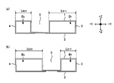
- 4 is a schematic cross-sectional view illustrating a closed cross-sectional portion B in the present disclosure
- FIG. 4 is a schematic cross-sectional view illustrating a closed cross-sectional portion B in the present disclosure
- FIG. 4 is a schematic cross-sectional view illustrating a closed cross-sectional portion B in the present disclosure
- FIG. 4 is a schematic cross-sectional view illustrating a closed cross-sectional portion B in the present disclosure
- FIG. 4 is a schematic cross-sectional view illustrating a closed cross-sectional portion B in the present disclosure
- FIG. 1A and 1B are schematic plan and cross-sectional views illustrating structural members of the present disclosure
- 1 is a schematic plan view illustrating a structural member in the present disclosure
- FIG. 1 is a schematic plan view illustrating a structural member in the present disclosure
- FIG. 2A and 2B are a schematic plan view and a schematic cross-sectional view of a geometric model of a structural member created in Example 1.
- FIG. 3A and 3B are a schematic plan view and a schematic cross-sectional view of a geometric model of a structural member created in Reference Example 1.
- FIG. 3A and 3B are a schematic plan view and a schematic cross-sectional view of a geometric model of a structural member created in Comparative Example 1.
- FIG. These are the evaluation results of Examples 1 to 3, Reference Example 1 and Comparative Example 1.
- FIG. 1 is a schematic plan view illustrating a structural member in the present disclosure, specifically illustrating a front lower arm.
- a structural member 10 shown in FIG. 1 is a member for connecting the lower part of a knuckle (not shown) that rotatably supports a wheel with a tire attached to an automobile body.
- An end portion T1 on one end side of the structural member 10 indicates the installation position of the ball joint attached to the knuckle.
- the end T 2 facing the end T 1 in the X-axis direction and the end T 3 located on the +Y direction side of the end T 2 are body members such as subframes (not shown). ) are shown.
- the structural member 10 is secured to the body member via , for example, bushing joints ( not shown) provided at ends T2 and T3.
- the structural member 10 is an L-shaped member. Specifically, where L SY is the length of the structural member 10 in the Y-axis direction, the structural member 10 has a curved shape in which L SY increases along the +X direction.
- the side of the curved shape with a larger radius of curvature may be referred to as the outer side of the curve, and the side of the curved shape with a smaller radius of curvature may be referred to as the inner side of the curve.
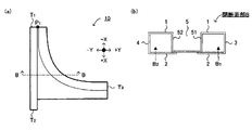
- FIG. 2 is a schematic plan view illustrating a structural member in the present disclosure
- FIG. 3 is a schematic cross-sectional view of the structural member shown in FIG.
- FIG. 3(a) is a sectional view taken along line AA in FIG. 2
- FIG. 3(b) is a sectional view taken along line CC in FIG. 2
- FIG. 3(c) is taken along line BB in FIG. It is a sectional view.
- the structural member 10 shown in FIG . 2 has an end T1 and an opposite end T2. Further, when the axial direction connecting the ends T1 and T2 is taken as the X - axis direction, the structural member 10 has a region A including the end T1 and a and a region B located on the end T2 side and including the end T2. Also, between the regions A and B, a region C, which is an intermediate region between the two, may be positioned.
- the region A shown in FIG. 2 has a closed cross section A whose outer edge shape is one closed cross section A in the cross section perpendicular to the X-axis direction.
- the term “closed cross section” means that the shape of the outer edge is closed in the cross section (the outer edge is endless and there is no end in the circumferential direction of the cross-sectional shape)
- a “closed cross-section portion” refers to a portion having a closed cross-section.
- the bottom surface portion 2 faces the top surface portion 1
- the first wall portion 3 connects the top surface portion 1 and the bottom surface portion 2
- the second wall portion 4 faces the first wall portion 3. , and connects the top surface portion 1 and the bottom surface portion 2 .
- the region B shown in FIG. It comprises a closed section B having a section B1 and a closed section B2.
- the closed cross section B1 is composed of the top surface portion 1 , the bottom surface portion 2, the first wall portion 3, and the wall portion 51 of the recessed portion 5
- the closed cross section B2 is composed of the top surface portion 1 , bottom portion 2 , second wall portion 4 , and wall portion 52 of recess 5 .
- the region B may include closed cross-sections B having an open cross-section B 1 and an open cross-section B 2 , each closed cross-section B being partitioned by the recess 5 .
- an open cross section B1 may be provided instead of the closed cross section B1
- an open cross section B2 may be provided instead of the closed cross section B2 .
- the term “open cross-section” means that the shape of the outer edge in the cross section is open (the outer edge has an edge and the edge exists in the circumferential direction in the cross-sectional shape).
- the depth d B of the recess 5 in the Z-axis direction in the closed cross-section B is 50% or more, and may be 70% or more, of the maximum length h B in the Z-axis direction of the closed cross-section B. , 80% or more, or 90% or more.
- the region C shown in FIG. 2 includes a closed cross-section portion C having a closed cross-section C as shown in FIG. 3(b).
- the shape of the closed cross section C changes continuously from the closed cross section A to the closed cross sections B1 and B2 along the +X direction.
- a closed cross-section C shown in FIG. 3B is composed of a top surface portion 1 in which a concave portion 5 is formed, a bottom surface portion 2, a first wall portion 3 and a second wall portion 4. As shown in FIG.
- the closed section B1 is arranged along the curved inner edge of the curved shape and the closed section B2 is arranged along the curved outer edge of the curved shape. It is Therefore, the closed cross section of the structural member 10 shown in FIG. 2 branches from the closed cross section A into the closed cross sections B1 and B2 along the +X direction. Since the closed section B in FIG. 2 places the material far from the neutral axis of bending, the geometrical moment of inertia of the structural member 10 can be increased.
- the structural member since the closed cross-sectional portion A and the closed cross-sectional portion B are provided as the closed cross-sectional portions perpendicular to the X-axis direction, the structural member has a good balance between bending strength and lightness.
- a load in the +Y direction is input to the center of a member (for example , a ball joint) attached to the end T1 shown in FIG. A force acts and the first wall 3 is subjected to a compressive load.
- the closed cross-section portion in the present disclosure functions as a load-bearing portion that suppresses out-of-plane deformation of the first wall portion 3 due to this compressive load.
- the closed cross-section portion B having good bending strength in the region B that is relatively strongly affected by the compressive load by arranging the closed cross-section portion B having good bending strength in the region B that is relatively strongly affected by the compressive load, the shape collapse of the closed cross-section portion B can be suppressed.
- the closed cross-section portion B has better bending strength than the closed cross-section portion A, it is disadvantageous in terms of lightness. Therefore, by arranging the closed cross-section portion A in the area A which is relatively unaffected by the compressive load, the lightness can be improved. In this way, a structural member having a good balance between bending strength and lightness can be obtained.
- Region A in the present disclosure is a region including end T1, as shown in FIG. Also, the region A has a closed cross-sectional portion A at the boundary between the region A and other adjacent regions (for example, the region B, the region C, or the region D).
- an arbitrary axis parallel to the X - axis direction and passing through the end T2 is defined as the X1 - axis
- the length of the region A in the X1-axis is defined as LAX
- the region of the X1 - axis Let LAY be the length of the region A in the Y-axis direction at an arbitrary point PA on A.
- the X1 axis may be an axis passing through a branch point, which will be described later.
- the arbitrary point P A may be the intersection of the X1 axis and the end T1 .
- the ratio of L AX to L AY (L AX /L AY ), at least at any point PA , is, for example, 0.5 or more, may be 1.0 or more, or 1.5 or more. good too. If L AX /L AY is too small, the effect of region A in improving lightness may be reduced. On the other hand, L AX /L AY satisfies, for example, 4.0 or less, may satisfy 3.5 or less, or may satisfy 3.0 or less at least at any point P A . If L AX /L AY is too large, the effect of region B on improving bending strength may be reduced.
- the length of region A on the X1 axis is L AX
- the length of region B on the X1 axis is L BX
- the length of region C on the X1 axis is L CX .
- the ratio of L AX to the sum of L BX and L CX (L TX ) (L AX /L TX ) is, for example, 0.10 or more, and may be 0.30 or more. If L AX /L TX is too small, the effect of region A in improving lightness may be reduced. On the other hand, L AX /L TX is, for example, 1.87 or less, and may be 0.95 or less.
- the distance from the end T1 to the end T2 on the X1 axis is, for example, 300 mm or more and 600 mm or less.
- the region A has a closed cross-sectional portion A whose outer edge shape is one closed cross-section A in a cross-section perpendicular to the X-axis direction. That is, the closed cross section A has only one closed cross section A as a closed cross section specified from its outer edge.
- the closed cross section is defined by the shape of the outer edge as described above. Therefore, even if a partition or the like is provided inside one closed cross section to divide the closed cross section into a plurality of regions inside, the closed cross section is regarded as one closed cross section.
- a structural member 10 shown in FIG. 19, which will be described later has a closed cross-section portion having two closed cross-sections with an outer edge shape on the end T1 side .
- Such a closed cross section does not correspond to the closed cross section A in the present disclosure.
- the closed cross section A is a closed cross section in which a predetermined concave portion is not provided.
- predetermined concave portion refers to a concave portion whose depth in the Z-axis direction of the closed cross-section A is 50% or more of the maximum length of the closed cross-section A in the Z-axis direction.
- the shape of the outer edge of the closed cross-section A is not particularly limited, but may be, for example, a polygon such as a rectangle, or a circle such as a perfect circle or an ellipse.
- the polygon in the present disclosure includes not only a strict polygon but also a shape in which portions corresponding to the corners of the polygon are formed in an arc shape.
- a closed cross section A shown in FIG. Although each side of the closed cross section is shown by a straight line in FIG. 6, each side of the closed cross section in the present disclosure is not limited to a straight line, and may be a curved line.
- the region A preferably has many regions in which the closed cross-sectional portions A are formed in the X-axis direction, and may include the closed cross-sectional portions A over the entire area in the X-axis direction.
- the closed cross-section portion A may be configured using one member.
- a structural member can be obtained, for example, by press-working a single metal plate and fixing it to form a closed cross-section.
- the fixing process for example, there is a method of fixing metal plates to each other. More specific examples of the fixing process include welding such as spot welding, laser welding, and arc welding, mechanical joining such as riveting, crimping, and bolting, and adhesion using an adhesive.
- a fixed portion is formed by the fixing process.
- the closed cross-section portion A may be configured using two or more members.
- a structural member can be obtained, for example, by pressing two or more metal plates, joining the different metal plates together, and performing a fixing process to form a closed cross section.
- the fixing process is the same as described above.
- the closed cross-section A shown in FIGS. 7(a) to (d) is a closed cross-section formed using one member.
- the fixed portion is formed on the top surface portion 1, and in the closed cross-section portion A shown in FIG. 7(b), the fixed portion is formed on the bottom surface portion 2.
- the fixed portion is formed on the first wall portion 3
- the fixed portion is formed on the second wall portion 4 in the closed cross-sectional portion A shown in FIG.
- the fixed portion is formed on the entire top surface portion, the bottom surface portion, the first wall portion, or the second wall portion, but the fixed portion is formed on at least a part. All you have to do is In FIGS. 8 to 11, which will be described later, fixing portions are formed at portions where the members are arranged so as to overlap each other, but the explanation of the fixing portions is omitted.
- the closed cross-section A shown in FIGS. 8A to 8F is a closed cross-section formed using two members.
- FIGS. 8A to 8F show a joining method in which two members are joined on the outer edge line at the fixed portion.
- S 1 to S 4 correspond to the top surface portion, the bottom surface portion, the first wall portion, or the second wall portion, respectively.
- S1 is the top surface portion
- S3 corresponds to the bottom surface portion
- one of S2 and S4 corresponds to the first wall portion
- the other corresponds to the second wall portion.
- S 1 and S 3 are expressed longer than S 2 and S 4 for the sake of convenience, but S 1 and S 3 are longer than S 2 and S 4 . It can be shorter or the same.
- S 1 to S 4 are the same in FIGS. 9 to 11, which will be described later.
- a member forming S 1 and members forming S 2 , S 3 and S 4 are used in the closed section A shown in FIGS. 8(a) to (d).
- the member forming S1 may be arranged to cover and join the members forming S2 , S3 and S4 .
- the members forming S 2 , S 3 and S 4 may be arranged and joined to cover the member forming S 1 .
- FIGS. 8(a) and (c) there are two fixing portions to which the member forming S1 and the members forming S2, S3 and S4 are fixed.
- the members constituting S 1 are arranged outside the members constituting S 2 , S 3 and S 4 and are unified.
- FIGS. 8(b) and 8(d) there are two fixing portions to which the member forming S1 and the members forming S2, S3 and S4 are fixed.
- the member forming S 1 is arranged inside the members forming S 2 , S 3 and S 4 to be unified.
- fixing portions may be formed in S2 and S4 , and as shown in FIGS. A part may be formed.
- members forming S1 and S4 and members forming S2 and S3 are used.
- the members forming S1 and S4 are arranged outside the members forming S2 and S3
- S 1 and S 4 are arranged inside the members constituting S 2 and S 3 and are not unified.
- the members arranged inside and the members arranged outside may or may not be unified.
- the closed cross section A shown in FIG . are formed using two members.
- the fixed portion may be formed by butting members (joining end surfaces of members) instead of overlapping members.
- the closed cross-section A shown in FIGS. 9(a) to (e) is also a closed cross-section formed by using two members, similarly to FIGS. 8(a) to (f).
- FIGS. 9A to 9E show a joining method in which at least one of two members has a flange portion in the fixed portion.
- members constituting S1 and S4 and members constituting S2 and S3 are used , and S2 and S4 each have a flange portion.
- S 1 , S 2 and S 4 and a member constituting S 3 are used, and S 2 and S 4 each have a flange portion. ing.
- a member forming S1 and members forming S2, S3 and S4 are used , and S1 has two flange portions. .
- members constituting S 1 , S 2 and S 4 and members constituting S 2 , S 3 and S 4 are used.
- Each S4 has a flange portion.
- members constituting S 1 and S 4 and members constituting S 2 and S 3 are used, and S 2 and S 3 each have a flange portion. ing.
- the portion where the flange portion is formed is not particularly limited. Further, when a plurality of fixing portions are provided, for example, the joining method shown in FIG. 8 and the joining method shown in FIG. 9 may be combined.
- the closed cross-section A shown in FIGS. 10A and 10B is a closed cross-section formed using four members.
- members forming S 1 to S 4 are used in the closed section A shown in FIGS. 10(a) and 10(b).
- the member forming S2 is arranged and joined so as to cover the member forming S1 and the member forming S4 .
- This joining method is the same as the joining method of the member constituting S1 in FIG. 8( a ).
- the joining method of each member is not limited to the joining method shown in FIG. 8(a), and the joining methods shown in FIGS. A joining method using a flange portion may be adopted as shown in FIG.
- the joining method of each member may be the same as each other, or may be different from each other.
- the members forming the sides of the closed cross section A may have a closed cross section structure.
- S 2 for example, the first wall portion
- a plurality of members forming sides of the closed cross section A may have a closed cross section structure.
- S 2 and S 4 for example, the first wall portion and the second wall portion
- the inside of the closed cross-section structure may be hollow or may be filled with a filler such as resin.
- Area B Region B in the present disclosure is a region located closer to end T2 than region A and including end T2, as shown in FIG .
- area B is an area on the +X direction side of the boundary between area B and other adjacent areas (for example, area A, area C, or area D).
- the region B has a closed cross-sectional portion B at the boundary between the region B and another adjacent region.
- the region B has a closed cross-sectional portion B that satisfies (i) or (ii) below.
- the closed cross section B that satisfies the above (i) is a closed cross section B 1 and a closed cross section B 2 that are connected via the bottom portion forming the recess and are arranged apart from each other in the cross section perpendicular to the X-axis direction.
- the closed cross-section portion B that satisfies the above (i) has a closed cross-section B1 and a closed cross - section B2 as closed cross-sections specified from its outer edge.
- the shape of the outer edge of the closed cross - section B1 and the closed cross-section B2 is not particularly limited, but examples thereof include polygons such as rectangles, and circles such as perfect circles and ellipses.
- the closed cross section B shown in FIG. 12( a ) has closed cross sections B 1 and B 2 which are connected via the bottom 53 forming the recess 5 and are spaced apart from each other.
- the closed cross section B1 is composed of the top surface portion 1 , the bottom surface portion 2, the first wall portion 3, and the wall portion 51 of the recessed portion 5.
- the closed cross section B2 is composed of the top surface portion 1, the bottom surface portion 2 , the second It is composed of the wall portion 4 and the wall portion 52 of the recess 5 .
- the length L ⁇ of the concave portion 5 in the Y-axis direction preferably increases along the +X direction (the direction from the back side to the front side of the paper in FIG. 12(a)).
- the distance between the closed cross-section B1 and the closed cross - section B2 increases along the +X direction.
- the closed cross section B1 is arranged along the inner edge of the curve
- the closed cross section B2 is arranged along the outer edge of the curve, and along the +X direction
- the closed cross-section B1 and the closed cross - section B2 move away from each other.
- the bottom portion 53 of the recessed portion 5 is located on the side of the bottom portion 2 ( ⁇ Z direction) with respect to the top portion 1 in a cross section perpendicular to the X-axis direction.
- the bottom of the recess may be arranged at a position on the top surface portion side (+Z direction) with the bottom surface portion as a reference in a cross section perpendicular to the X-axis direction.
- the bottom 53 of the recess 5 has a portion formed continuously from the wall 51 and the wall 52. As shown in FIG. The bottom portion 2 is discontinuously formed at the bottom portion 53 .
- the bottom portion 53 of the recessed portion 5 has a portion formed continuously from the bottom surface portion 2 . In the bottom portion 53, the portion continuously formed from the wall portion 51 and the portion continuously formed from the wall portion 52 are discontinuous.
- the length L B1Y of the closed cross section B1 in the Y - axis direction and the length L B2Y of the closed cross-section B2 in the Y-axis direction may be the same or different.
- L B1Y is greater than L B2Y .
- L B2Y is greater than L B1Y .
- the closed cross-section portion B that satisfies the above (ii) has an open cross-section B1 and an open cross-section B2 in which one closed cross-section B is partitioned by a recess in a cross-section perpendicular to the X - axis direction.
- the closed cross section B shown in FIG. 14( a ) has an open cross section B 1 and an open cross section B 2 in which one closed cross section B is partitioned by the recess 5 .
- the depth d B of the recess 5 in the Z-axis direction in the closed cross-section B is 50% or more of the maximum length h B in the Z-axis direction of the closed cross-section B.
- the bottom portion 53 of the recessed portion 5 may be arranged at a position on the side of the bottom surface portion 2 ( ⁇ Z direction) with the top surface portion 1 as a reference in a cross section perpendicular to the X-axis direction.
- the bottom of the recess may be arranged at a position on the top surface portion side (+Z direction) with the bottom surface portion as a reference in a cross section perpendicular to the X-axis direction.
- the depth d B may be approximately 100% of the maximum length h B .
- the bottom portion 53 of the concave portion 5 and the bottom surface portion 2 may be in contact with each other.
- the closed section B has a closed section B1 and a closed section B2. Further, when the bottom portion 53 of the recessed portion 5 and the bottom portion 2 are in contact with each other, a fixing portion for fixing them may be formed.
- the closed cross-section portion B may be configured using one member, or may be configured using two or more members. These matters are the same as the contents described for the closed cross-section portion A described above, except for the concave portion.
- a structural member in the present disclosure may have a region C located between regions A and B in the X-axis direction, as shown in FIG.
- the shape of the closed cross section in the cross section of the structural member perpendicular to the X-axis direction is changed from the closed cross section A to the closed cross section.
- Part B is an area that changes continuously. That is, the closed cross-sectional portion of the structural member is formed such that the cross-sectional shape changes continuously from the closed cross-sectional portion A to the closed cross-sectional portion B along the +X direction.
- the region C has a closed cross section C having a closed cross section C in a cross section perpendicular to the X-axis direction.
- the closed cross-section portion C may have only one closed cross-section C as a closed cross-section specified from its outer edge.
- the shape of the closed cross-section C is not particularly limited, but is the same as that described for the closed cross-section A except for the concave portion.
- a closed cross-section C shown in FIG. 3B is composed of a top surface portion 1 in which a concave portion 5 is formed, a bottom surface portion 2, a first wall portion 3 and a second wall portion 4. As shown in FIG. Also, the depth of the recess 5 in the closed section C is defined as dC.
- Region C has a branch point (closed cross-section branch point) located at the boundary between closed cross-section portion A and closed cross-section portion C.
- FIG. 15(a) is a schematic plan view illustrating a structural member in the present disclosure
- FIG. 15(b) is a cross-sectional view taken along line CX - CX of FIG. 15(a).
- the C X -C X axis is an axis that is parallel to the X-axis direction and passes through a branch point located on the boundary between the closed cross-sectional area A and the closed cross-sectional area C.
- the depth dC of the recess 5 in the region C (closed cross section C ) is along the +X direction (the direction from the end T1 to the end T2) grow continuously.
- the depth dC at the boundary between regions A and C is 0, the depth dC increases along the +X direction, and the depth dC at the boundary between regions B and C is 0.
- C coincides with the depth d B (the depth of the recess 5 in the closed section B).
- the boundary line between the area C and the area A is the boundary on the C X -C X axis, that is, the line passing through the branch point and parallel to the Y axis direction.
- a boundary line between the regions C and B is a line parallel to the Y-axis direction passing through the boundary on the C X -C X -axis.
- the region C has a closed cross-sectional portion C over the entire area from the boundary with the region A to the boundary with the region B in the X-axis direction.
- the closed cross-section portion C may be configured using one member, or may be configured using two or more members.
- the structural member in the present disclosure may not have region C.
- the closed cross section A in the region A changed discontinuously to the closed cross sections B1 and B2 in the region B. It becomes a structural member.
- the boundary between the area A and the area B is the boundary between the closed cross-sectional area A and the closed cross-sectional area B.
- the structural member in the present disclosure has an unillustrated region consisting of an open cross section, or an unillustrated closed cross section having a discontinuous closed cross section A , closed cross section B1 , and closed cross section B2.
- One or a plurality of regions may be provided along the direction ( + X direction) from end T1 to end T2. That is, the region A and the region B are arranged apart from each other, and between the region A and the region B, there is an open cross-sectional region, or a discontinuous closed cross - section A, closed cross-section B1 and closed cross-section B2.
- One or more regions having closed cross-sections may be provided.
- a region D is defined as a region having an open cross section over the entire area. That is, the region D is located between the regions A and B and has an open cross section throughout. Further, in a plan view of the structural member, the closed cross-sectional portion A branches toward the closed cross-sectional portion B, and the region D has a branch point located on the boundary with the closed cross-sectional portion A.
- the cross-sectional shape of the region D is a shape without the bottom portion 2 located in the region C in the C X -C X cross-sectional view of FIG. 15(a).
- a boundary line between the area D and the area A is a line passing through the branch point and parallel to the Y-axis direction.
- a boundary line between the area D and the area B is a line parallel to the Y-axis direction passing through the boundary on the D X -D X -axis.
- the structural member in the present disclosure preferably has a curved shape in plan view.
- the curved shape is a shape in which the length of the structural member 10 in the Y-axis direction increases along the +X direction, as shown in FIG. That is, the curved shape is such that the length of the structural member 10 in the Y-axis direction at the position relatively on the end T1 side is LSY1 , and the length of the structural member 10 at the position relatively on the end T2 side in the Y-axis direction is LSY1.
- the shape satisfies L SY1 ⁇ L SY2 , where L SY2 is the length in the direction.
- the center of curvature of the curved inner edge ⁇ of the curved shape is located outside the structural member 10 .
- the first wall portion 3 may be arranged along the curved inner edge ⁇ of the curved shape.
- the second wall portion 4 may be arranged along the curved outer edge portion ⁇ of the curved shape.
- the material constituting the structural member in the present disclosure is not particularly limited, but for example, metal materials such as steel, aluminum alloys, and magnesium alloys, and resin materials containing fibers such as glass fiber and carbon fiber and resin (for example, CFRP) is mentioned. Also, the structural member may be a composite material of a metal material and a resin material.
- the material constituting the structural member it is preferable that at least a steel plate is used as the material constituting the structural member.
- the tensile strength of the metal plate such as steel plate is not particularly limited, it is, for example, 780 MPa or more, and may be 980 MPa or more.
- the thickness of the metal plate such as steel plate is, for example, 1 mm or more and 3 mm or less.
- FIG. 17 is a schematic plan view illustrating structural members in the present disclosure, and more specifically, a schematic plan view illustrating a front lower arm.
- the maximum length of the front lower arm in the vehicle front-rear direction is, for example, 260 mm or more and 460 mm or less.
- the maximum length of the front lower arm in the vehicle width direction is, for example, 260 mm or more and 460 mm or less.
- the maximum length of the front lower arm in the vehicle height direction is, for example, 30 mm or more and 100 mm or less.
- the structural members of the present disclosure can also be used, for example, in mobile bodies such as motorcycles, ships, and aircraft, and architectural structures.
- the present disclosure is not limited to the above embodiments.
- the above embodiment is an example, and any device that has substantially the same configuration as the technical idea described in the claims of the present disclosure and produces the same effect is the present invention. It is included in the technical scope of the disclosure.
- FIG. 18(a) is a schematic plan view of the shape model of the structural member created in Example 1
- FIG. 18(b) is a cross-sectional view along AA of FIG. 18(a)
- FIG. 18(a) is a cross-sectional view taken along line BB of FIG. 18(a).
- the structural member 10 shown in FIG. 18(a) has the ends T 1 , T 2 and T 3 described above, and further has regions A, B and C. As shown in FIG. The middle point in the Y - axis direction of the end portion T1 was defined as the point P1. Also, L AX /L AY was set to 1.0. Let L AX be the length of region A on the X1 axis (not shown) passing through the bifurcation located at the boundary of closed cross section A and closed cross section C , and L AY be the length of X1 axis and end T1. The length in the Y-axis direction of the region A at the intersection point. 18(a), the region A in the structural member 10 shown in FIG.
- FIG. 18(a) is composed of a top surface portion 1, a bottom surface portion 2, a first wall portion 3 and a second wall portion 4, as shown in FIG. 18(b).
- a closed section A having a closed section A is provided.
- the region B in the structural member 10 shown in FIG. 18(a) has a closed cross-section portion B having a closed cross-section B1 and a closed cross-section B2, which are arranged apart from each other, as shown in FIG. 18(c).
- Example 2 A shape model of a structural member was created in the same manner as in Example 1, except that L AX /L AY was changed to 2.0.
- Example 3 A shape model of a structural member was created in the same manner as in Example 1, except that L AX /L AY was changed to 3.0.
- FIG. 19(a) is a schematic plan view of the shape model of the structural member created in Reference Example 1
- FIG. 19(b) is a cross-sectional view taken along line BB of FIG. 19(a).
- FIGS. 19A and 19B a shape model of a structural member was created in the same manner as in Example 1, except that the closed cross-sectional portion B was formed over the entire area along the X-axis direction.
- FIG. 20(a) is a schematic plan view of the geometric model of the structural member prepared in Comparative Example 1
- FIG. 20(b) is a cross-sectional view taken along line AA of FIG. 20(a).
- the top surface portion 11 having the recess 15 formed thereon, and the first wall portion A shape model of a structural member was created in the same manner as in Example 1, except that an open cross-section portion having 13 and a second wall portion 14 was formed.
- Examples 1 to 3 had higher maximum load values per unit weight than Comparative Example 1. That is, compared to the structural member of Comparative Example 1 (structural member having an open cross section), the structural members of Examples 1 to 3 (structural members having a predetermined closed cross section) had a better balance between bending strength and lightness. It was confirmed to be good.
- Examples 1 to 3 had a higher maximum load value per unit weight than Reference Example 1.
- the structural member of Reference Example 1 has only the closed cross-sectional portion B
- the structural member of Example 1 has, in addition to the closed cross-sectional portion B, a closed cross-sectional portion A that is light in weight. Therefore, it is presumed that the balance between bending strength and lightness became better.
Landscapes
- Engineering & Computer Science (AREA)
- Mechanical Engineering (AREA)
- Body Structure For Vehicles (AREA)
- Vehicle Body Suspensions (AREA)
- Rod-Shaped Construction Members (AREA)
Priority Applications (5)
| Application Number | Priority Date | Filing Date | Title |
|---|---|---|---|
| JP2023521218A JP7560788B2 (ja) | 2021-05-11 | 2022-05-11 | 構造部材 |
| MX2023012836A MX2023012836A (es) | 2021-05-11 | 2022-05-11 | Miembro estructural. |
| US18/288,911 US12358333B2 (en) | 2021-05-11 | 2022-05-11 | Structural member |
| CN202280031136.1A CN117203069A (zh) | 2021-05-11 | 2022-05-11 | 构造构件 |
| EP22807493.6A EP4338987A4 (en) | 2021-05-11 | 2022-05-11 | STRUCTURAL ELEMENT |
Applications Claiming Priority (2)
| Application Number | Priority Date | Filing Date | Title |
|---|---|---|---|
| JP2021-080138 | 2021-05-11 | ||
| JP2021080138 | 2021-05-11 |
Publications (1)
| Publication Number | Publication Date |
|---|---|
| WO2022239794A1 true WO2022239794A1 (ja) | 2022-11-17 |
Family
ID=84029698
Family Applications (1)
| Application Number | Title | Priority Date | Filing Date |
|---|---|---|---|
| PCT/JP2022/019907 Ceased WO2022239794A1 (ja) | 2021-05-11 | 2022-05-11 | 構造部材 |
Country Status (6)
| Country | Link |
|---|---|
| US (1) | US12358333B2 (https=) |
| EP (1) | EP4338987A4 (https=) |
| JP (1) | JP7560788B2 (https=) |
| CN (1) | CN117203069A (https=) |
| MX (1) | MX2023012836A (https=) |
| WO (1) | WO2022239794A1 (https=) |
Citations (4)
| Publication number | Priority date | Publication date | Assignee | Title |
|---|---|---|---|---|
| JPS58218407A (ja) * | 1982-06-14 | 1983-12-19 | Hiruta Kogyo Kk | 自動車前輪懸架装置のi形ア−ムの構造 |
| JP2007153254A (ja) * | 2005-12-08 | 2007-06-21 | Toyota Motor Corp | トレーリング・アーム式サスペンション構造 |
| JP2013082341A (ja) * | 2011-10-11 | 2013-05-09 | Toyota Motor Corp | サスペンションアーム |
| WO2019103152A1 (ja) | 2017-11-27 | 2019-05-31 | 日本製鉄株式会社 | 構造部材 |
Family Cites Families (16)
| Publication number | Priority date | Publication date | Assignee | Title |
|---|---|---|---|---|
| JPH08318722A (ja) | 1995-03-23 | 1996-12-03 | Toyota Motor Corp | サスペンションアーム |
| JP3191654B2 (ja) * | 1995-08-30 | 2001-07-23 | トヨタ自動車株式会社 | サスペンションアーム |
| JP3613702B2 (ja) * | 1999-09-21 | 2005-01-26 | トヨタ自動車株式会社 | 閉断面を有する構造部材、その製造装置およびその製造方法 |
| JP4488398B2 (ja) * | 2000-12-28 | 2010-06-23 | 富士重工業株式会社 | サスペンションアーム |
| ITTO20010253A1 (it) * | 2001-03-16 | 2002-09-16 | Sistemi Sospensioni Spa | Elemento strutturale per una sospensione di un autoveicolo e procedimento per la sua realizzazione. |
| JP2004262453A (ja) * | 2004-06-07 | 2004-09-24 | F Tech:Kk | 車両用サスペンションアーム |
| WO2006056046A2 (en) * | 2004-11-23 | 2006-06-01 | Magna International Inc. | Method for forming a bumper beam for a motor vehicle |
| DE102005008548A1 (de) * | 2005-02-23 | 2006-08-24 | Zf Friedrichshafen Ag | Lenker, insbesondere Querlenker, für eine Fahrzeugradaufhängung |
| EA015065B1 (ru) * | 2007-04-04 | 2011-04-29 | Сумитомо Метал Индастриз, Лтд. | Несущий элемент для кузова автомобиля, передний боковой элемент и боковая конструкция для кузова автомобиля |
| JP2010023713A (ja) * | 2008-07-22 | 2010-02-04 | F Tech:Kk | 金属製アーム部材及びその製造方法 |
| IT1400618B1 (it) * | 2010-05-12 | 2013-06-14 | Sistemi Sospensioni Spa | Elemento strutturale in materiale composito, particolarmente per sospensione di veicolo |
| CN112384385B (zh) | 2018-07-05 | 2024-03-05 | 格鲁帕冲压有限责任公司 | 具有加强特征的车辆悬架部件 |
| CN112566800A (zh) | 2018-08-20 | 2021-03-26 | 格鲁帕冲压有限责任公司 | 具有增强特征和连接节点的车辆悬架部件 |
| JP7128700B2 (ja) * | 2018-09-20 | 2022-08-31 | 株式会社Subaru | 繊維強化樹脂構造体 |
| MX2021010230A (es) * | 2019-02-26 | 2021-09-21 | Jfe Steel Corp | Miembro estructural para vehiculo. |
| CN114025894B (zh) * | 2019-07-04 | 2023-10-24 | 日本制铁株式会社 | 构造部件的制造方法以及制造装置 |
-
2022
- 2022-05-11 MX MX2023012836A patent/MX2023012836A/es unknown
- 2022-05-11 CN CN202280031136.1A patent/CN117203069A/zh active Pending
- 2022-05-11 EP EP22807493.6A patent/EP4338987A4/en active Pending
- 2022-05-11 JP JP2023521218A patent/JP7560788B2/ja active Active
- 2022-05-11 WO PCT/JP2022/019907 patent/WO2022239794A1/ja not_active Ceased
- 2022-05-11 US US18/288,911 patent/US12358333B2/en active Active
Patent Citations (4)
| Publication number | Priority date | Publication date | Assignee | Title |
|---|---|---|---|---|
| JPS58218407A (ja) * | 1982-06-14 | 1983-12-19 | Hiruta Kogyo Kk | 自動車前輪懸架装置のi形ア−ムの構造 |
| JP2007153254A (ja) * | 2005-12-08 | 2007-06-21 | Toyota Motor Corp | トレーリング・アーム式サスペンション構造 |
| JP2013082341A (ja) * | 2011-10-11 | 2013-05-09 | Toyota Motor Corp | サスペンションアーム |
| WO2019103152A1 (ja) | 2017-11-27 | 2019-05-31 | 日本製鉄株式会社 | 構造部材 |
Non-Patent Citations (1)
| Title |
|---|
| See also references of EP4338987A4 |
Also Published As
| Publication number | Publication date |
|---|---|
| JP7560788B2 (ja) | 2024-10-03 |
| JPWO2022239794A1 (https=) | 2022-11-17 |
| MX2023012836A (es) | 2023-11-13 |
| EP4338987A4 (en) | 2025-04-23 |
| US12358333B2 (en) | 2025-07-15 |
| EP4338987A1 (en) | 2024-03-20 |
| CN117203069A (zh) | 2023-12-08 |
| US20240198746A1 (en) | 2024-06-20 |
Similar Documents
| Publication | Publication Date | Title |
|---|---|---|
| US8616570B2 (en) | Method for producing a control arm, and a control arm | |
| CN114829236B (zh) | 仪表板支架 | |
| CN1697740A (zh) | 工字梁结构汽车悬架臂 | |
| JP7020492B2 (ja) | 構造部材 | |
| CN105946972A (zh) | 一种环保型铝合金汽车副车架 | |
| CN105365894B (zh) | 一种车身后部斜撑结构 | |
| CN101072696A (zh) | 包括梯形横截面横梁的挠性轴、相应的横梁、车辆以及制造方法 | |
| CN102233799B (zh) | 壳式结构的横向连杆 | |
| WO2022239794A1 (ja) | 構造部材 | |
| KR20170023830A (ko) | 차량 섀시 구조체 | |
| CN217994574U (zh) | 一种商用车驾驶室顶盖总成 | |
| CN102267490B (zh) | 一种基于内高压成形的汽车纵梁及其制造方法 | |
| JPH08188022A (ja) | 車両用サスペンションアーム | |
| CN110588792A (zh) | 一种适用于电动车的框架式铝合金型材前端模块结构 | |
| CN104249760A (zh) | 一种汽车前纵梁结构及制造方法 | |
| CN206679075U (zh) | 一种低压铸造一体式前纵梁 | |
| CN210734294U (zh) | 一种适用于电动车的框架式前端模块结构 | |
| CN108639156A (zh) | 白车身及其制造工艺 | |
| JP6376010B2 (ja) | 自動車のサスペンション系部材、その本体およびその製造方法 | |
| JP7368730B2 (ja) | リアサブフレーム | |
| CN116714678A (zh) | 一种汽车车身结构及汽车 | |
| WO2002083466A1 (en) | Stiffeners for automotive sheet body structure | |
| JP7522342B2 (ja) | 構造部品 | |
| JP6428067B2 (ja) | 自動車用部材 | |
| CN218806106U (zh) | 副车架以及车辆 |
Legal Events
| Date | Code | Title | Description |
|---|---|---|---|
| 121 | Ep: the epo has been informed by wipo that ep was designated in this application |
Ref document number: 22807493 Country of ref document: EP Kind code of ref document: A1 |
|
| WWE | Wipo information: entry into national phase |
Ref document number: 2023521218 Country of ref document: JP |
|
| WWE | Wipo information: entry into national phase |
Ref document number: 202317072809 Country of ref document: IN Ref document number: 202280031136.1 Country of ref document: CN |
|
| WWE | Wipo information: entry into national phase |
Ref document number: MX/A/2023/012836 Country of ref document: MX |
|
| WWE | Wipo information: entry into national phase |
Ref document number: 18288911 Country of ref document: US |
|
| WWE | Wipo information: entry into national phase |
Ref document number: 2022807493 Country of ref document: EP |
|
| NENP | Non-entry into the national phase |
Ref country code: DE |
|
| ENP | Entry into the national phase |
Ref document number: 2022807493 Country of ref document: EP Effective date: 20231211 |
|
| WWG | Wipo information: grant in national office |
Ref document number: 18288911 Country of ref document: US |