WO2022224887A1 - ガス供給システム、基板処理装置、及びガス供給システムの運用方法 - Google Patents
ガス供給システム、基板処理装置、及びガス供給システムの運用方法 Download PDFInfo
- Publication number
- WO2022224887A1 WO2022224887A1 PCT/JP2022/017694 JP2022017694W WO2022224887A1 WO 2022224887 A1 WO2022224887 A1 WO 2022224887A1 JP 2022017694 W JP2022017694 W JP 2022017694W WO 2022224887 A1 WO2022224887 A1 WO 2022224887A1
- Authority
- WO
- WIPO (PCT)
- Prior art keywords
- gas
- gas supply
- heat transfer
- pressure
- supply system
- Prior art date
- Legal status (The legal status is an assumption and is not a legal conclusion. Google has not performed a legal analysis and makes no representation as to the accuracy of the status listed.)
- Ceased
Links
Images









Classifications
-
- C—CHEMISTRY; METALLURGY
- C23—COATING METALLIC MATERIAL; COATING MATERIAL WITH METALLIC MATERIAL; CHEMICAL SURFACE TREATMENT; DIFFUSION TREATMENT OF METALLIC MATERIAL; COATING BY VACUUM EVAPORATION, BY SPUTTERING, BY ION IMPLANTATION OR BY CHEMICAL VAPOUR DEPOSITION, IN GENERAL; INHIBITING CORROSION OF METALLIC MATERIAL OR INCRUSTATION IN GENERAL
- C23C—COATING METALLIC MATERIAL; COATING MATERIAL WITH METALLIC MATERIAL; SURFACE TREATMENT OF METALLIC MATERIAL BY DIFFUSION INTO THE SURFACE, BY CHEMICAL CONVERSION OR SUBSTITUTION; COATING BY VACUUM EVAPORATION, BY SPUTTERING, BY ION IMPLANTATION OR BY CHEMICAL VAPOUR DEPOSITION, IN GENERAL
- C23C16/00—Chemical coating by decomposition of gaseous compounds, without leaving reaction products of surface material in the coating, i.e. chemical vapour deposition [CVD] processes
- C23C16/44—Chemical coating by decomposition of gaseous compounds, without leaving reaction products of surface material in the coating, i.e. chemical vapour deposition [CVD] processes characterised by the method of coating
- C23C16/455—Chemical coating by decomposition of gaseous compounds, without leaving reaction products of surface material in the coating, i.e. chemical vapour deposition [CVD] processes characterised by the method of coating characterised by the method used for introducing gases into reaction chamber or for modifying gas flows in reaction chamber
- C23C16/45557—Pulsed pressure or control pressure
-
- C—CHEMISTRY; METALLURGY
- C23—COATING METALLIC MATERIAL; COATING MATERIAL WITH METALLIC MATERIAL; CHEMICAL SURFACE TREATMENT; DIFFUSION TREATMENT OF METALLIC MATERIAL; COATING BY VACUUM EVAPORATION, BY SPUTTERING, BY ION IMPLANTATION OR BY CHEMICAL VAPOUR DEPOSITION, IN GENERAL; INHIBITING CORROSION OF METALLIC MATERIAL OR INCRUSTATION IN GENERAL
- C23C—COATING METALLIC MATERIAL; COATING MATERIAL WITH METALLIC MATERIAL; SURFACE TREATMENT OF METALLIC MATERIAL BY DIFFUSION INTO THE SURFACE, BY CHEMICAL CONVERSION OR SUBSTITUTION; COATING BY VACUUM EVAPORATION, BY SPUTTERING, BY ION IMPLANTATION OR BY CHEMICAL VAPOUR DEPOSITION, IN GENERAL
- C23C16/00—Chemical coating by decomposition of gaseous compounds, without leaving reaction products of surface material in the coating, i.e. chemical vapour deposition [CVD] processes
- C23C16/44—Chemical coating by decomposition of gaseous compounds, without leaving reaction products of surface material in the coating, i.e. chemical vapour deposition [CVD] processes characterised by the method of coating
- C23C16/50—Chemical coating by decomposition of gaseous compounds, without leaving reaction products of surface material in the coating, i.e. chemical vapour deposition [CVD] processes characterised by the method of coating using electric discharges
- C23C16/505—Chemical coating by decomposition of gaseous compounds, without leaving reaction products of surface material in the coating, i.e. chemical vapour deposition [CVD] processes characterised by the method of coating using electric discharges using radio frequency discharges
-
- H—ELECTRICITY
- H01—ELECTRIC ELEMENTS
- H01J—ELECTRIC DISCHARGE TUBES OR DISCHARGE LAMPS
- H01J37/00—Discharge tubes with provision for introducing objects or material to be exposed to the discharge, e.g. for the purpose of examination or processing thereof
- H01J37/32—Gas-filled discharge tubes
- H01J37/32431—Constructional details of the reactor
- H01J37/32715—Workpiece holder
- H01J37/32724—Temperature
-
- H—ELECTRICITY
- H10—SEMICONDUCTOR DEVICES; ELECTRIC SOLID-STATE DEVICES NOT OTHERWISE PROVIDED FOR
- H10P—GENERIC PROCESSES OR APPARATUS FOR THE MANUFACTURE OR TREATMENT OF DEVICES COVERED BY CLASS H10
- H10P50/00—Etching of wafers, substrates or parts of devices
- H10P50/20—Dry etching; Plasma etching; Reactive-ion etching
- H10P50/24—Dry etching; Plasma etching; Reactive-ion etching of semiconductor materials
- H10P50/242—Dry etching; Plasma etching; Reactive-ion etching of semiconductor materials of Group IV materials
-
- H—ELECTRICITY
- H10—SEMICONDUCTOR DEVICES; ELECTRIC SOLID-STATE DEVICES NOT OTHERWISE PROVIDED FOR
- H10P—GENERIC PROCESSES OR APPARATUS FOR THE MANUFACTURE OR TREATMENT OF DEVICES COVERED BY CLASS H10
- H10P72/00—Handling or holding of wafers, substrates or devices during manufacture or treatment thereof
- H10P72/04—Apparatus for manufacture or treatment
- H10P72/0402—Apparatus for fluid treatment
-
- H—ELECTRICITY
- H10—SEMICONDUCTOR DEVICES; ELECTRIC SOLID-STATE DEVICES NOT OTHERWISE PROVIDED FOR
- H10P—GENERIC PROCESSES OR APPARATUS FOR THE MANUFACTURE OR TREATMENT OF DEVICES COVERED BY CLASS H10
- H10P72/00—Handling or holding of wafers, substrates or devices during manufacture or treatment thereof
- H10P72/04—Apparatus for manufacture or treatment
- H10P72/0431—Apparatus for thermal treatment
-
- H—ELECTRICITY
- H10—SEMICONDUCTOR DEVICES; ELECTRIC SOLID-STATE DEVICES NOT OTHERWISE PROVIDED FOR
- H10P—GENERIC PROCESSES OR APPARATUS FOR THE MANUFACTURE OR TREATMENT OF DEVICES COVERED BY CLASS H10
- H10P72/00—Handling or holding of wafers, substrates or devices during manufacture or treatment thereof
- H10P72/04—Apparatus for manufacture or treatment
- H10P72/0431—Apparatus for thermal treatment
- H10P72/0434—Apparatus for thermal treatment mainly by convection
-
- H—ELECTRICITY
- H10—SEMICONDUCTOR DEVICES; ELECTRIC SOLID-STATE DEVICES NOT OTHERWISE PROVIDED FOR
- H10P—GENERIC PROCESSES OR APPARATUS FOR THE MANUFACTURE OR TREATMENT OF DEVICES COVERED BY CLASS H10
- H10P72/00—Handling or holding of wafers, substrates or devices during manufacture or treatment thereof
- H10P72/06—Apparatus for monitoring, sorting, marking, testing or measuring
- H10P72/0604—Process monitoring, e.g. flow or thickness monitoring
-
- H—ELECTRICITY
- H10—SEMICONDUCTOR DEVICES; ELECTRIC SOLID-STATE DEVICES NOT OTHERWISE PROVIDED FOR
- H10P—GENERIC PROCESSES OR APPARATUS FOR THE MANUFACTURE OR TREATMENT OF DEVICES COVERED BY CLASS H10
- H10P72/00—Handling or holding of wafers, substrates or devices during manufacture or treatment thereof
- H10P72/70—Handling or holding of wafers, substrates or devices during manufacture or treatment thereof for supporting or gripping
- H10P72/72—Handling or holding of wafers, substrates or devices during manufacture or treatment thereof for supporting or gripping using electrostatic chucks
- H10P72/722—Details of electrostatic chucks
-
- C—CHEMISTRY; METALLURGY
- C23—COATING METALLIC MATERIAL; COATING MATERIAL WITH METALLIC MATERIAL; CHEMICAL SURFACE TREATMENT; DIFFUSION TREATMENT OF METALLIC MATERIAL; COATING BY VACUUM EVAPORATION, BY SPUTTERING, BY ION IMPLANTATION OR BY CHEMICAL VAPOUR DEPOSITION, IN GENERAL; INHIBITING CORROSION OF METALLIC MATERIAL OR INCRUSTATION IN GENERAL
- C23C—COATING METALLIC MATERIAL; COATING MATERIAL WITH METALLIC MATERIAL; SURFACE TREATMENT OF METALLIC MATERIAL BY DIFFUSION INTO THE SURFACE, BY CHEMICAL CONVERSION OR SUBSTITUTION; COATING BY VACUUM EVAPORATION, BY SPUTTERING, BY ION IMPLANTATION OR BY CHEMICAL VAPOUR DEPOSITION, IN GENERAL
- C23C16/00—Chemical coating by decomposition of gaseous compounds, without leaving reaction products of surface material in the coating, i.e. chemical vapour deposition [CVD] processes
- C23C16/44—Chemical coating by decomposition of gaseous compounds, without leaving reaction products of surface material in the coating, i.e. chemical vapour deposition [CVD] processes characterised by the method of coating
- C23C16/458—Chemical coating by decomposition of gaseous compounds, without leaving reaction products of surface material in the coating, i.e. chemical vapour deposition [CVD] processes characterised by the method of coating characterised by the method used for supporting substrates in the reaction chamber
- C23C16/4582—Rigid and flat substrates, e.g. plates or discs
- C23C16/4583—Rigid and flat substrates, e.g. plates or discs the substrate being supported substantially horizontally
-
- C—CHEMISTRY; METALLURGY
- C23—COATING METALLIC MATERIAL; COATING MATERIAL WITH METALLIC MATERIAL; CHEMICAL SURFACE TREATMENT; DIFFUSION TREATMENT OF METALLIC MATERIAL; COATING BY VACUUM EVAPORATION, BY SPUTTERING, BY ION IMPLANTATION OR BY CHEMICAL VAPOUR DEPOSITION, IN GENERAL; INHIBITING CORROSION OF METALLIC MATERIAL OR INCRUSTATION IN GENERAL
- C23C—COATING METALLIC MATERIAL; COATING MATERIAL WITH METALLIC MATERIAL; SURFACE TREATMENT OF METALLIC MATERIAL BY DIFFUSION INTO THE SURFACE, BY CHEMICAL CONVERSION OR SUBSTITUTION; COATING BY VACUUM EVAPORATION, BY SPUTTERING, BY ION IMPLANTATION OR BY CHEMICAL VAPOUR DEPOSITION, IN GENERAL
- C23C16/00—Chemical coating by decomposition of gaseous compounds, without leaving reaction products of surface material in the coating, i.e. chemical vapour deposition [CVD] processes
- C23C16/44—Chemical coating by decomposition of gaseous compounds, without leaving reaction products of surface material in the coating, i.e. chemical vapour deposition [CVD] processes characterised by the method of coating
- C23C16/46—Chemical coating by decomposition of gaseous compounds, without leaving reaction products of surface material in the coating, i.e. chemical vapour deposition [CVD] processes characterised by the method of coating characterised by the method used for heating the substrate
- C23C16/463—Cooling of the substrate
- C23C16/466—Cooling of the substrate using thermal contact gas
Definitions
- Exemplary embodiments of the present disclosure relate to a gas supply system, a substrate processing apparatus, and a method of operating the gas supply system.
- Patent Document 1 discloses a plasma processing apparatus as a type of substrate processing apparatus.
- a plasma processing apparatus includes a chamber and a mounting table.
- a mounting table is provided in the chamber.
- the mounting table is configured to support a substrate mounted thereon.
- the plasma processing apparatus is configured to supply a heat transfer gas to a gap between the mounting table and the substrate to promote heat exchange between the mounting table and the substrate.
- the present disclosure provides a technique for suppressing the consumption of heat transfer gas.
- a gas delivery system comprising a gas supply line and a gas recovery line.
- a gas supply line is configured to supply a heat transfer gas to a gap between the substrate support and the back surface of the substrate.
- the gas supply line includes a first portion, a second portion, a third portion and a pressure controller.
- the second portion is downstream with respect to the first portion.
- a pressure controller is configured to regulate the pressure of the heat transfer gas and is connected between the first portion and the second portion.
- a third portion connects the second portion and the gap.
- a gas recovery line connects to the first portion and the second portion.
- a gas recovery line includes a pump connected between the first portion and the second portion. The gas recovery line shares the third portion with the gas supply line.
- a gas recovery line is configured to return the heat transfer gas from the second portion to the first portion.
- FIG. 1 schematically illustrates a substrate processing apparatus according to one exemplary embodiment
- FIG. 1 schematically illustrates a substrate processing apparatus according to one exemplary embodiment
- FIG. 1 illustrates a gas delivery system according to one exemplary embodiment
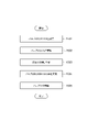
- FIG. 4 is a flow chart illustrating a gas delivery sequence according to one exemplary embodiment
- 4 is a flow chart illustrating a gas shutdown sequence according to one exemplary embodiment
- FIG. 4 illustrates a gas supply system according to another exemplary embodiment
- FIG. 5 illustrates a gas supply system according to yet another exemplary embodiment
- 4 is a flow chart illustrating a gas supply sequence according to another exemplary embodiment
- 4 is a flow chart illustrating a gas shutdown sequence according to another exemplary embodiment
- FIG. 5 illustrates a gas supply system according to yet another exemplary embodiment
- 4 is a flow chart illustrating a gas delivery sequence in accordance with yet another exemplary embodiment
- FIG. 4 is a flow chart illustrating a gas shutdown sequence in accordance with yet another exemplary embodiment
- FIG. 5 illustrates a gas supply system according to yet another exemplary embodiment
- 4 is a flow chart illustrating a gas delivery sequence in accordance with yet another exemplary embodiment
- FIG. 4 is a flow chart illustrating a gas shutdown sequence in accordance with yet another exemplary embodiment
- FIG. FIG. 5 illustrates a gas supply system according to yet another exemplary embodiment
- a gas delivery system comprising a gas supply line and a gas recovery line.
- a gas supply line is configured to supply a heat transfer gas to a gap between the substrate support and the back surface of the substrate.
- the gas supply line includes a first portion, a second portion, a third portion and a pressure controller.
- the second portion is downstream with respect to the first portion.
- a pressure controller is configured to regulate the pressure of the heat transfer gas and is connected between the first portion and the second portion.
- a third portion connects the second portion and the gap.
- a gas recovery line connects to the first portion and the second portion.
- a gas recovery line includes a pump connected between the first portion and the second portion. The gas recovery line shares the third portion with the gas supply line.
- a gas recovery line is configured to return the heat transfer gas from the second portion to the first portion.
- the heat transfer gas supplied to the gap between the substrate support and the back surface of the substrate is returned to the first portion of the gas supply line and reused. Therefore, consumption of heat transfer gas is suppressed.
- the gas supply line and the gas return line share a third section with each other, and the heat transfer gas is returned to the first section from the second section, which connects to the third section. Therefore, an unintended increase in gas pressure in the third portion and the gap can be suppressed.
- the gas return line may further include a gas passageway connected between the second portion and the pump, and an orifice that reduces the cross-sectional area of the gas passageway. good.
- the gas recovery line may further include another gas flow path connected between the second portion and the pump.
- the gas recovery line further includes a gas flow path connected between the second portion and the pump, and a valve capable of adjusting the opening of the gas flow path. good too.
- the opening of the valve may be set to be less than fully open when the heat transfer gas is being supplied to the gap from the gas supply line.
- the third portion may include a valve connected between the second portion and the substrate support.
- the first portion may include a tank for storing heat transfer gas.
- a gas recovery line may be configured to return the heat transfer gas to the tank.
- the gas supply system may further comprise a pressure regulator.
- the pressure regulator is configured to regulate the pressure of the heat transfer gas in the portion of the gas supply line upstream to the pressure controller.
- the pressure regulator may include a pressure gauge and valve.
- a pressure gauge is configured to measure the pressure of the heat transfer gas within the tank.
- a valve is connected between the source of heat transfer gas and the first portion and opens and closes in response to the pressure measured by the pressure gauge.
- the pressure regulator may set the pressure in the portion of the gas supply line upstream to the pressure controller to a pressure higher than the required supply pressure of the pressure controller.
- the gas supply system may further comprise another gas supply line and another gas recovery line.
- Another gas supply line is configured to supply a heat transfer gas to the gap.
- Another gas supply line includes the first portion, another second portion, another pressure controller, and another third portion.
- Another second portion is downstream with respect to the first portion.
- Another pressure controller is configured to regulate the pressure of the heat transfer gas and is connected between the first portion and another second portion.
- Another third portion connects another second portion and the gap.
- Another gas recovery line is connected to the first portion and the separate second portion.
- Another gas recovery line is connected between the first portion and another second portion.
- Another gas recovery line is configured to return heat transfer gas from another second portion to the first portion.
- a substrate processing apparatus comprises a substrate support and a gas supply system according to any of the exemplary embodiments described above.
- the substrate support is configured to support a substrate placed thereon.
- a gas supply system is configured to supply a heat transfer gas to a gap between the substrate support and the backside of the substrate.
- a method of operating the gas supply system of any of the exemplary embodiments described above includes supplying a heat transfer gas to a gap between the substrate support and the back surface of the substrate via a gas supply line.
- the method of operation further includes partially withdrawing the heat transfer gas from the second portion to the first portion with the gas recovery line as the heat transfer gas is being supplied to the gap.
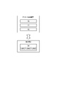
- FIG 1 and 2 are diagrams schematically showing a substrate processing apparatus according to one exemplary embodiment.
- the substrate processing apparatus is a plasma processing system.
- the plasma processing system includes a plasma processing apparatus 1 and a controller 2.
- the plasma processing apparatus 1 includes a plasma processing chamber 10 , a substrate support 11 and a plasma generation section 12 .
- Plasma processing chamber 10 has a plasma processing space.
- the plasma processing chamber 10 also has at least one gas inlet for supplying at least one process gas to the plasma processing space and at least one gas outlet for exhausting gas from the plasma processing space.
- the gas supply port is connected to a gas supply section 20, which will be described later, and the gas discharge port is connected to an exhaust system 40, which will be described later.
- the substrate support 11 is arranged in the plasma processing space and has a substrate support surface for supporting the substrate.
- the plasma generation unit 12 is configured to generate plasma from at least one processing gas supplied into the plasma processing space.
- Plasma formed in the plasma processing space includes capacitively coupled plasma (CCP), inductively coupled plasma (ICP), ECR plasma (Electron-Cyclotron-resonance plasma), helicon wave excited plasma (HWP: Helicon Wave Plasma), surface wave plasma (SWP: Surface Wave Plasma), or the like.
- Various types of plasma generators may also be used, including alternating current (AC) plasma generators and direct current (DC) plasma generators.
- the AC signal (AC power) used in the AC plasma generator has a frequency within the range of 100 kHz to 10 GHz. Therefore, AC signals include RF (Radio Frequency) signals and microwave signals.
- the RF signal has a frequency within the range of 200 kHz-150 MHz.
- the controller 2 processes computer-executable instructions that cause the plasma processing apparatus 1 to perform the various steps described in this disclosure. Controller 2 may be configured to control elements of plasma processing apparatus 1 to perform the various processes described herein. In one embodiment, part or all of the controller 2 may be included in the plasma processing apparatus 1 .
- the control unit 2 may include, for example, a computer 2a.
- the computer 2a may include, for example, a processing unit (CPU: Central Processing Unit) 2a1, a storage unit 2a2, and a communication interface 2a3. Processing unit 2a1 can be configured to perform various control operations based on programs stored in storage unit 2a2.
- the storage unit 2a2 may include RAM (Random Access Memory), ROM (Read Only Memory), HDD (Hard Disk Drive), SSD (Solid State Drive), or a combination thereof.
- the communication interface 2a3 may communicate with the plasma processing apparatus 1 via a communication line such as a LAN (Local Area Network).
- the capacitively coupled plasma processing apparatus 1 includes a plasma processing chamber 10, a gas supply section 20, a power supply 30 and an exhaust system 40. As shown in FIG. Further, the plasma processing apparatus 1 includes a substrate support section 11 and a gas introduction section. The gas introduction is configured to introduce at least one process gas into the plasma processing chamber 10 .
- the gas introduction section includes a showerhead 13 .
- a substrate support 11 is positioned within the plasma processing chamber 10 .
- the showerhead 13 is arranged above the substrate support 11 . In one embodiment, showerhead 13 forms at least a portion of the ceiling of plasma processing chamber 10 .
- the plasma processing chamber 10 has a plasma processing space 10 s defined by a showerhead 13 , side walls 10 a of the plasma processing chamber 10 and a substrate support 11 . Side wall 10a is grounded.
- the showerhead 13 and substrate support 11 are electrically insulated from the housing of the plasma processing chamber 10 .
- the substrate support section 11 includes a body section 111 and a ring assembly 112 .
- the body portion 111 has a central region (substrate support surface) 111 a for supporting the substrate (wafer) W and an annular region (ring support surface) 111 b for supporting the ring assembly 112 .
- the annular region 111b of the body portion 111 surrounds the central region 111a of the body portion 111 in plan view.
- the substrate W is arranged on the central region 111 a of the main body 111
- the ring assembly 112 is arranged on the annular region 111 b of the main body 111 so as to surround the substrate W on the central region 111 a of the main body 111 .
- body portion 111 includes a base and an electrostatic chuck.
- the base includes an electrically conductive member.
- the conductive member of the base functions as a lower electrode.
- An electrostatic chuck is arranged on the base.
- the upper surface of the electrostatic chuck has a substrate support surface 111a.
- Ring assembly 112 includes one or more annular members. At least one of the one or more annular members is an edge ring.
- the substrate supporter 11 may include a temperature control module configured to control at least one of the electrostatic chuck, the ring assembly 112, and the substrate W to a target temperature.
- the temperature control module may include heaters, heat transfer media, flow paths, or combinations thereof.
- the showerhead 13 is configured to introduce at least one processing gas from the gas supply unit 20 into the plasma processing space 10s.
- the showerhead 13 has at least one gas supply port 13a, at least one gas diffusion chamber 13b, and a plurality of gas introduction ports 13c.
- the processing gas supplied to the gas supply port 13a passes through the gas diffusion chamber 13b and is introduced into the plasma processing space 10s through a plurality of gas introduction ports 13c.
- showerhead 13 also includes a conductive member.
- a conductive member of the showerhead 13 functions as an upper electrode.
- the gas introduction part may include one or more side gas injectors (SGI: Side Gas Injector) attached to one or more openings formed in the side wall 10a.
- SGI Side Gas Injector
- the gas supply unit 20 may include at least one gas source 21 and at least one flow controller 22.
- gas supply 20 is configured to supply at least one process gas from respective gas sources 21 through respective flow controllers 22 to showerhead 13 .
- Each flow controller 22 may include, for example, a mass flow controller or a pressure controlled flow controller.
- gas supply 20 may include at least one flow modulation device for modulating or pulsing the flow rate of at least one process gas.
- Power supply 30 includes an RF power supply 31 coupled to plasma processing chamber 10 via at least one impedance matching network.
- the RF power supply 31 is configured to supply at least one RF signal (RF power), such as a source RF signal and a bias RF signal, to the conductive members of the substrate support 11 and/or the conductive members of the showerhead 13. be done.
- RF power RF signal
- the RF power supply 31 can function as at least part of the plasma generator 12 .
- a bias potential is generated in the substrate W, and ion components in the formed plasma can be drawn into the substrate W.
- the RF power supply 31 includes a first RF generator 31a and a second RF generator 31b.
- the first RF generator 31a is coupled to the conductive member of the substrate support 11 and/or the conductive member of the showerhead 13 via at least one impedance matching circuit to provide a source RF signal for plasma generation (source RF electrical power).
- the source RF signal has a frequency within the range of 13 MHz to 150 MHz.
- the first RF generator 31a may be configured to generate multiple source RF signals having different frequencies. The generated one or more source RF signals are provided to conductive members of the substrate support 11 and/or conductive members of the showerhead 13 .
- the second RF generator 31b is coupled to the conductive member of the substrate support 11 via at least one impedance matching circuit and configured to generate a bias RF signal (bias RF power).
- the bias RF signal has a lower frequency than the source RF signal.
- the bias RF signal has a frequency within the range of 400 kHz to 13.56 MHz.
- the second RF generator 31b may be configured to generate multiple bias RF signals having different frequencies.
- One or more bias RF signals generated are provided to the conductive members of the substrate support 11 .
- at least one of the source RF signal and the bias RF signal may be pulsed.
- Power supply 30 may also include a DC power supply 32 coupled to plasma processing chamber 10 .
- the DC power supply 32 includes a first DC generator 32a and a second DC generator 32b.
- the first DC generator 32a is connected to a conductive member of the substrate support 11 and configured to generate the first DC signal.
- the generated first DC signal is applied to the conductive member of substrate support 11 .
- the first DC signal may be applied to other electrodes, such as electrodes in an electrostatic chuck.
- the second DC generator 32b is connected to the conductive member of the showerhead 13 and configured to generate the second DC signal.
- the generated second DC signal is applied to the conductive members of showerhead 13 .
- the first and second DC signals may be pulsed. Note that the first and second DC generators 32a and 32b may be provided in addition to the RF power supply 31, and the first DC generator 32a may be provided instead of the second RF generator 31b. good.
- the exhaust system 40 may be connected to a gas exhaust port 10e provided at the bottom of the plasma processing chamber 10, for example.
- Exhaust system 40 may include a pressure regulating valve and a vacuum pump.
- the pressure regulating valve regulates the pressure in the plasma processing space 10s.
- Vacuum pumps may include turbomolecular pumps, dry pumps, or combinations thereof.
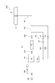
- FIG. 3 is a diagram of a gas supply system according to one exemplary embodiment.
- the gas supply system 50 shown in FIG. 3 can be employed in a substrate processing apparatus such as the plasma processing apparatus 1, for example.
- the gas supply system 50 includes a gas supply line 51 and a gas recovery line 52 .
- the gas supply line 51 is configured to supply a heat transfer gas (for example, helium gas) to the gap between the substrate supporting portion 11 and the back surface of the substrate W. As shown in FIG.
- the gas supply line 51 includes a first portion P1, a second portion P2, a third portion P3, and a pressure controller PC.
- the first part P1 provides a gas flow path connected to a source GS of heat transfer gas.
- the second portion P2 is downstream of the first portion P1.
- the second portion P2 provides a gas flow path for the heat transfer gas.
- a pressure controller PC is connected between the first part P1 and the second part P2.
- a third portion P3 is downstream of the second portion P2 and provides a gas flow path for the heat transfer gas.
- the third portion P3 connects the second portion P2 and the gap between the substrate supporting portion 11 and the back surface of the substrate W to each other.
- heat transfer gas is directed from source GS to substrate support 11 and substrate W through first portion P1, pressure controller PC, second portion P2, and third portion P3. It is supplied to the gap between the back surface.
- the first portion P1 may include the tank TA.
- Tank TA is a vessel in which heat transfer gas is stored.
- valve V1 and pressure regulator PR may be connected between first portion P1 and source GS.
- the valve V1 may be an open/close valve or a valve whose opening degree can be adjusted.
- the pressure regulator PR is configured to regulate the pressure of the heat transfer gas in the upstream (primary) portion of the gas supply line 51 with respect to the pressure controller PC.
- pressure regulator PR may be a pressure regulator.
- the pressure regulator PR may set the pressure of the heat transfer gas in the portion of the gas supply line 51 upstream to the pressure controller PC to a pressure higher than the required supply pressure of the pressure controller PC.
- the required supply pressure of the pressure controller PC can be greater than or equal to the maximum pressure of the heat transfer gas output by the pressure controller PC.
- the pressure of the heat transfer gas that the pressure regulator PR outputs to the upstream portion of the pressure controller PC in the gas supply line 51 is designated to the pressure regulator PR by the controller 2, for example.
- the pressure controller PC is configured to control the pressure of the heat transfer gas output downstream (secondary side) in the gas supply line 51 .
- the pressure of the heat transfer gas that the pressure controller PC outputs to its downstream side is designated to the pressure controller PC by the controller 2, for example.
- a valve V21 may be connected between the first portion P1 and the pressure controller PC.
- a valve V22 may also be connected between the pressure controller PC and the second part P2.
- Each of the valve V21 and the valve V22 may be an open/close valve, or may be a valve whose opening degree is adjustable.
- the gas recovery line 52 is connected to the first portion P1 and the second portion P2.
- Gas recovery line 52 includes a gas flow path connected between first portion P1 and second portion P2.
- Gas recovery line 52 further includes pump PU.
- Pump PU is connected between first portion P ⁇ b>1 and second portion P ⁇ b>2 and forms part of the gas flow path of gas recovery line 52 .
- a gas recovery line 52 is configured to return heat transfer gas from the second portion P2 to the first portion P1.
- gas recovery line 52 is configured to return heat transfer gas from second portion P2 to tank TA.
- Gas recovery line 52 shares third portion P3 with gas supply line 51 .
- gas recovery line 52 may include first recovery line 521 and second recovery line 522 .
- a first recovery line 521 provides a gas flow path connecting the second portion P2 and the pump PU.
- First recovery line 521 further includes valve V3 and orifice OF.
- Valve V3 and orifice OF partially configure the gas flow path of first recovery line 521 .
- the valve V3 may be an open/close valve or a valve whose opening degree can be adjusted.
- the orifice OF reduces the cross-sectional area of the gas flow path of the first recovery line 521 .
- the second recovery line 522 provides another gas flow path connecting the second portion P2 and the pump PU. That is, the first recovery line 521 and the second recovery line 522 are connected in parallel between the second portion P2 and the pump PU.
- Second recovery line 522 further includes valve V4.
- Valve V4 partially configures the gas flow path of second recovery line 522 .
- the valve V4 may be an open/close valve or a valve whose opening degree can be adjusted.
- the second collection line 522 does not include an orifice. That is, the minimum cross-sectional area of the gas flow path of the second recovery line 522 is larger than the minimum cross-sectional area of the gas flow path of the first recovery line 521 .
- the operating method includes a step of supplying a heat transfer gas to the gap between the substrate supporting portion 11 and the back surface of the substrate W through the gas supply line 51 .
- the method of operation further includes partially withdrawing the heat transfer gas from the second portion P2 to the first portion P1 by the gas recovery line 52 as the heat transfer gas is being supplied to the gap.
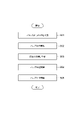
- FIG. 4 is a flow chart illustrating a gas delivery sequence according to one exemplary embodiment.
- Each part of the gas supply system 50 can be controlled by the controller 2 in the gas supply sequence.
- the heat transfer gas is supplied to the gap between the substrate supporting portion 11 and the back surface of the substrate W through the gas supply line 51 . Further, the heat transfer gas is partially returned from the second portion P2 to the first portion P1 by the gas recovery line 52 by executing the gas supply sequence.
- valve V1 is first opened (step 401).
- Valve V21, valve V22, and valve V3 are then opened (step 402).
- the pressure controller PC controls the pressure of the heat transfer gas (step 403).
- the pump PU is operated to return a portion of the heat transfer gas from the second portion P2 back to the first portion P1.
- the heat transfer gas at the specified pressure is supplied to the gap between the substrate support 11 and the back surface of the substrate W.
- the heat transfer gas is also partially returned from the second portion P2 to the first portion P1 by the gas recovery line 52 .
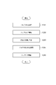
- FIG. 5 is a flow chart illustrating a gas shutdown sequence according to one exemplary embodiment.
- Each part of the gas supply system 50 can be controlled by the controller 2 in the gas stop sequence.
- the controller 2 By executing the gas stop sequence, the supply of the heat transfer gas by the gas supply system 50 is stopped.
- valves V21 and V3 are first closed (step 501).
- Valve V4 is then opened (step 502).
- valves V22 and V4 are closed (step 504).
- Valve V1 is then closed (step 505).
- the pump PU is activated to return the heat transfer gas to the first portion P1. Due to this gas stop sequence, the supply of the heat transfer gas to the gap between the substrate supporting portion 11 and the back surface of the substrate W is stopped. Also, the heat transfer gas in the second portion P2, the third portion P3, and the gas recovery line 52 of the gas supply system 50 is returned into the first portion P1 (eg, tank TA).
- the heat transfer gas supplied to the gap between the substrate supporting portion 11 and the back surface of the substrate W is returned to the first portion P1 of the gas supply line 51, and used. Therefore, consumption of heat transfer gas is suppressed.
- the gas supply line 51 and the gas recovery line 52 share a third portion P3 with each other, and the heat transfer gas is returned to the first portion P1 from the second portion P2 connected to the third portion P3. be Therefore, an unintended increase in gas pressure in the third portion P3 and the gap can be suppressed. Further, the gas supply line 51 and the gas recovery line 52 share the third portion P3, thereby simplifying the gas line configuration.
- FIG. 6 is a diagram of a gas supply system according to another exemplary embodiment;
- a gas supply system 50B shown in FIG. 6 can be employed in a substrate processing apparatus such as the plasma processing apparatus 1, for example.
- pressure regulator PR includes valve V1 and pressure gauge PM.
- a pressure gauge PM is arranged to measure the pressure in the tank TA. The opening/closing or degree of opening of the valve V1 is controlled by the controller 2 so that the pressure measured by the pressure gauge PM becomes a specified pressure.
- Each other configuration of the gas supply system 50B is identical to the corresponding configuration of the gas supply system 50B.
- the operation method, gas supply sequence, and gas stop sequence described above can also be applied to the gas supply system 50B.
- FIG. 7 is a diagram illustrating a gas supply system according to yet another exemplary embodiment
- a gas supply system 50C shown in FIG. 7 can be employed in a substrate processing apparatus such as the plasma processing apparatus 1, for example.
- a third portion P3 of gas delivery system 50C includes valve V6.
- the valve V6 partially configures the gas flow path of the third portion P3.
- the valve V6 may be an open/close valve or a valve whose opening degree can be adjusted.
- Gas supply system 50C does not include valve V22.
- Each of the other configurations of gas supply system 50C are identical to the corresponding configurations of gas supply system 50C.
- the operation method described above can also be applied to the gas supply system 50C.
- FIG. 8 is a flow chart showing a gas supply sequence according to another exemplary embodiment.
- valve V1 in the gas supply sequence applied to the gas supply system 50C, valve V1 is first opened (step 801).
- Valve V21, valve V3, and valve V6 are then opened (step 802).
- the valve V4 is closed while the gas supply sequence is being executed.
- the pressure controller PC then controls the pressure of the heat transfer gas (step 803).
- the pump PU is operated to return a portion of the heat transfer gas from the second portion P2 back to the first portion P1.
- FIG. 9 is a flow chart showing a gas shutdown sequence according to another exemplary embodiment.
- valves V21, V3, and V6 are first closed (step 901).
- Valve V4 is then opened (step 902).
- valve V4 is closed (step 904).
- Valve V1 is then closed (step 905).
- the pump PU is activated to return the heat transfer gas to the first portion P1.
- the gas supply system 50C prevents the process gas in the plasma processing chamber 10 from returning to the first portion P1 during execution of the gas stop sequence.
- FIG. 10 is a diagram illustrating a gas supply system according to yet another exemplary embodiment
- a gas supply system 50D shown in FIG. 10 can be employed in a substrate processing apparatus such as the plasma processing apparatus 1, for example.
- the gas recovery line 52 does not include the first recovery line 521 and the second recovery line 522, and is a single gas line connected between the second portion P2 and the pump PU. Provides a flow path.
- the gas recovery line 52 includes a valve V3C whose opening can be adjusted. Valve V3C forms part of the single gas flow path of gas recovery line 52 .
- Each other configuration of gas supply system 50D is identical to the corresponding configuration of gas supply system 50.
- FIG. Moreover, the operation method described above can also be applied to the gas supply system 50D.
- FIG. 11 is a flow chart showing a gas supply sequence according to yet another exemplary embodiment.
- valve V1 in the gas supply sequence applied to the gas supply system 50D, valve V1 is first opened (step 1101).
- Valve V21, valve V22, and valve V3C are then opened (step 1102).
- the opening of valve V3C is set to less than full opening to return a small amount of heat transfer gas from second portion P2 to first portion P1.
- the pressure controller PC then controls the pressure of the heat transfer gas (step 1103).
- the pump PU is operated to return a portion of the heat transfer gas from the second portion P2 back to the first portion P1.
- FIG. 12 is a flow chart showing a gas shutdown sequence according to yet another exemplary embodiment.
- the valve V21 in the gas stop sequence applied to the gas supply system 50D, the valve V21 is first closed (step 1202).
- Valve V3C is then opened (step 1202).
- the opening of the valve V3C is set to a higher opening than that during execution of the gas supply sequence, for example, fully open.
- valves V22 and V3C are closed (step 1204).
- Valve V1 is then closed (step 1205).
- the pump PU is activated to return the heat transfer gas to the first portion P1.
- FIG. 13 is a diagram illustrating a gas supply system according to yet another exemplary embodiment
- a gas supply system 50E shown in FIG. 13 can be employed in a substrate processing apparatus such as the plasma processing apparatus 1, for example.
- the gas supply system 50E further includes a gas supply line 51E and a gas recovery line 52E.
- the gas supply line 51E like the gas supply line 51, is configured to supply a heat transfer gas to the gap between the substrate supporting portion 11 and the back surface of the substrate W.
- the gas supply line 51E includes a second portion P2E, a pressure controller PCE and a third portion P3E. Gas supply line 51E shares first portion P1 with gas supply line 51 .
- the second portion P2E is downstream of the first portion P1.
- the second portion P2E provides a gas flow path for the heat transfer gas.
- a pressure controller PCE is connected between the first part P1 and the second part P2E.
- the pressure controller PCE is configured to control the pressure of the heat transfer gas output downstream thereof in the gas supply line 51E.
- the pressure of the heat transfer gas that the pressure controller PCE outputs to its downstream side is designated by the controller 2 to the pressure controller PCE, for example.
- pressure controller PCE is connected to first part P1 via valve V21.
- the pressure controller PCE is also connected to the second part P2E via valve V22E.
- the valve V22E may be an open/close valve or a valve whose degree of opening can be adjusted.
- the third portion P3E is downstream of the second portion P2E and provides a gas flow path for the heat transfer gas.
- the third portion P3E connects the second portion P2E and the gap between the substrate supporting portion 11 and the back surface of the substrate W to each other.
- heat transfer gas is directed from source GS to substrate support 11 and substrate W through first portion P1, pressure controller PCE, second portion P2E, and third portion P3E. It is supplied to the gap between the back surface.
- the gas recovery line 52E is connected to the first portion P1 and the second portion P2E.
- Gas recovery line 52E includes a gas flow path connected between first portion P1 and second portion P2E.
- Gas recovery line 52E shares pump PU with gas recovery line 52 .
- the pump PU partially configures the gas flow path of the gas recovery line 52 and the gas flow path of the gas recovery line 52E.
- a gas recovery line 52E is configured to return heat transfer gas from the second portion P2E to the first portion P1.
- gas recovery line 52E is configured to return gas from second portion P2E to tank TA.
- Gas recovery line 52E shares a third portion P3E with gas supply line 51E.
- the gas recovery line 52E may include a first recovery line 521E and a second recovery line 522E.
- the first recovery line 521E provides a gas flow path connecting the second portion P2E and the pump PU.
- First collection line 521E further includes valve V3E and orifice OFE.
- Valve V3E and orifice OFE partially form the gas flow path of first recovery line 521E.
- the valve V3E may be an open/close valve or a valve whose opening degree can be adjusted.
- the orifice OFE reduces the cross-sectional area of the gas flow path of the first recovery line 521E.
- the second recovery line 522E provides another gas flow path connecting the second portion P2E and the pump PU. That is, the first recovery line 521E and the second recovery line 522E are connected in parallel between the second portion P2E and the pump PU. Second recovery line 522E further includes valve V4E. Valve V4E partially configures the gas flow path of second recovery line 522E.
- the valve V4E may be an open/close valve or a valve whose opening degree can be adjusted. Note that the second recovery line 522E does not include an orifice. That is, the minimum cross-sectional area of the gas channel of the second recovery line 522E is larger than the minimum cross-sectional area of the gas channel of the first recovery line 521E.
- each other configuration of the gas supply system 50E is identical to the corresponding configuration of the gas supply system 50.
- the operation method described above can also be applied to the gas supply system 50E.
- the operating method includes a step of supplying a heat transfer gas to the gap between the substrate supporting portion 11 and the back surface of the substrate W through the gas supply lines 51 and 51E.
- the method of operation includes partially recovering the heat transfer gas from the second portions P2 and P2E to the first portion P1 by the gas recovery lines 52 and 52E as the heat transfer gas is supplied to the gap. Including further.
- each part of the gas supply system 50E can be controlled by the controller 2.
- the heat transfer gas is supplied to the gap between the substrate supporting portion 11 and the back surface of the substrate W through the gas supply lines 51 and 51E.
- the gas supply sequence is also performed such that the heat transfer gas is partially returned from the second portions P2 and P2E to the first portion P1 by the gas recovery lines 52 and 52E.
- FIG. 14 is a flow chart showing a gas supply sequence according to yet another exemplary embodiment.
- valve V1 in the gas supply sequence applied to the gas supply system 50E, valve V1 is first opened (step 1401).
- Valve V21, valve V22, valve V22E, valve V3, and valve V3E are then opened (step 1402). It should be noted that the valves V4 and V4E are closed while the gas supply sequence is being executed.
- the pressure of the heat transfer gas is then controlled by pressure controllers PC and PCE (step 1403).
- the pump PU is operated to return a portion of the heat transfer gas from the second portions P2 and P2E to the first portion P1.
- the heat transfer gas at the specified pressure is supplied to the gap between the substrate support 11 and the back surface of the substrate W. As shown in FIG. Heat transfer gas is also partially returned to the first portion P1 from the second portions P2 and P2E by gas return lines 52 and 52E.
- each part of the gas supply system 50E can be controlled by the controller 2.
- the controller 2 By executing the gas stop sequence, the supply of the heat transfer gas by the gas supply system 50E is stopped.
- FIG. 15 is a flow chart showing a gas shutdown sequence according to yet another exemplary embodiment.
- valves V21, V3, and V3E are first closed (step 1501). Valves V4 and V4E are then opened (step 1502). Then, after waiting a desired amount of time (step 1503), valves V22, V22E, V4, and V4E are closed (step 1504). Valve V1 is then closed (step 1505).
- the pump PU is activated to return the heat transfer gas to the first portion P1. Due to this gas stop sequence, the supply of the heat transfer gas to the gap between the substrate supporting portion 11 and the back surface of the substrate W is stopped. Also, the heat transfer gas in the second portions P2 and P2E, the third portions P3 and P3E, and the gas recovery lines 52 and 52E of the gas supply system 50 is transferred into the first portion P1 (e.g., tank TA). returned.
- the first portion P1 e.g., tank TA
- FIG. 16 is a diagram illustrating a gas supply system according to yet another exemplary embodiment
- a gas supply system 50F shown in FIG. 16 differs from the gas supply system 50 in that it further includes a pressure intensifier PI, a filter FT, and a check valve CV.
- a pressure intensifier PI, a filter FT and a check valve CV are connected between the pump PU and the first part P1 (eg tank TA).
- Pump PU may be a turbomolecular pump.
- each of the gas supply systems according to the various embodiments described above may further include a pressure intensifier PI, a filter FT, and a check valve CV, similar to the gas supply system 50F.
- the pressure intensifier PI increases the pressure of the gas recovered by the gas recovery line 52 .
- the gas pressurized by the pressure intensifier PI is returned to the first portion P1 (eg tank TA).
- the pressure intensifier PI may be a dry pump, compressor, or the like.
- the check valve CV is provided to prevent backflow of gas from the gas supply line 51 to the gas recovery line 52 .
- a filter FT is connected between the check valve CV and the pressure intensifier PI. The filter FT is configured to trap and remove components other than the heat transfer gas.
- the components removed by the filter FT are oil in the pressure intensifier PI, mechanical dust in the exhaust system, dust from the back surface of the substrate and the substrate support (e.g., electrostatic chuck), degassing from the piping, and residues in the chamber. May contain gas.
- gas supply systems of the various embodiments described above may be employed in substrate processing apparatuses other than plasma processing apparatuses.
- gas supply system 50E includes two gas supply lines and two gas recovery lines
- the gas supply system includes three or more gas supply lines and three or more gas recovery lines. May contain lines.
- an exhaust device may be connected to the second recovery line 522 between the valve V4 and the pump PU.
- At least one other gas supply line may be connected to the gas flow path of the gas supply line 51 between the valve V21 and the pressure controller PC.
- At least one additional gas supply line is provided to supply heat transfer gas to a gap between the substrate support of the at least one additional substrate processing apparatus and the back surface of the substrate.
- At least one further gas supply line like gas supply line 51, may include a pressure controller, a valve, a second portion, and a third portion. The pressure controller, the valve, the second portion, and the third portion in the at least one other gas supply line are between the valve V21 and the substrate support of the at least one other substrate processing apparatus and the back surface of the substrate. connected across the gap.
- a first recovery line and a second recovery line may be connected between the second portion of at least one other gas supply line and the pump PU, similar to the gas recovery line 52 .
Landscapes
- Chemical & Material Sciences (AREA)
- Engineering & Computer Science (AREA)
- Chemical Kinetics & Catalysis (AREA)
- General Chemical & Material Sciences (AREA)
- Materials Engineering (AREA)
- Mechanical Engineering (AREA)
- Metallurgy (AREA)
- Organic Chemistry (AREA)
- Plasma & Fusion (AREA)
- Physics & Mathematics (AREA)
- Analytical Chemistry (AREA)
- Drying Of Semiconductors (AREA)
- Filling Or Discharging Of Gas Storage Vessels (AREA)
Priority Applications (4)
| Application Number | Priority Date | Filing Date | Title |
|---|---|---|---|
| JP2023515432A JP7702479B2 (ja) | 2021-04-21 | 2022-04-13 | ガス供給システム、基板処理装置、及びガス供給システムの運用方法 |
| CN202280028055.6A CN117121171A (zh) | 2021-04-21 | 2022-04-13 | 气体供给系统、基板处理装置及气体供给系统的运行方法 |
| US18/555,432 US12553132B2 (en) | 2021-04-21 | 2022-04-13 | Gas supply system, substrate processing apparatus, and operation method for gas supply system |
| KR1020237038317A KR20230171955A (ko) | 2021-04-21 | 2022-04-13 | 가스 공급 시스템, 기판 처리 장치, 및 가스 공급 시스템의 운용 방법 |
Applications Claiming Priority (2)
| Application Number | Priority Date | Filing Date | Title |
|---|---|---|---|
| JP2021-071667 | 2021-04-21 | ||
| JP2021071667 | 2021-04-21 |
Publications (1)
| Publication Number | Publication Date |
|---|---|
| WO2022224887A1 true WO2022224887A1 (ja) | 2022-10-27 |
Family
ID=83722937
Family Applications (1)
| Application Number | Title | Priority Date | Filing Date |
|---|---|---|---|
| PCT/JP2022/017694 Ceased WO2022224887A1 (ja) | 2021-04-21 | 2022-04-13 | ガス供給システム、基板処理装置、及びガス供給システムの運用方法 |
Country Status (5)
| Country | Link |
|---|---|
| US (1) | US12553132B2 (https=) |
| JP (1) | JP7702479B2 (https=) |
| KR (1) | KR20230171955A (https=) |
| CN (1) | CN117121171A (https=) |
| WO (1) | WO2022224887A1 (https=) |
Families Citing this family (1)
| Publication number | Priority date | Publication date | Assignee | Title |
|---|---|---|---|---|
| WO2025250431A1 (en) * | 2024-05-31 | 2025-12-04 | Lam Research Corporation | Dual backside gas supply system |
Citations (4)
| Publication number | Priority date | Publication date | Assignee | Title |
|---|---|---|---|---|
| JPH07249586A (ja) * | 1993-12-22 | 1995-09-26 | Tokyo Electron Ltd | 処理装置及びその製造方法並びに被処理体の処理方法 |
| JPH10240356A (ja) * | 1997-02-21 | 1998-09-11 | Anelva Corp | 基板処理装置の基板温度制御法と基板温度制御性判定法 |
| JP2013153171A (ja) * | 2013-02-15 | 2013-08-08 | Panasonic Corp | プラズマ処理装置及びプラズマ処理方法 |
| JP2017530545A (ja) * | 2014-09-12 | 2017-10-12 | アプライド マテリアルズ インコーポレイテッドApplied Materials,Incorporated | 静電チャックのためのガス効率の向上 |
Family Cites Families (10)
| Publication number | Priority date | Publication date | Assignee | Title |
|---|---|---|---|---|
| JP3055847B2 (ja) * | 1993-07-02 | 2000-06-26 | 東京エレクトロン株式会社 | 減圧処理装置 |
| US6949202B1 (en) | 1999-10-26 | 2005-09-27 | Reflectivity, Inc | Apparatus and method for flow of process gas in an ultra-clean environment |
| US7041224B2 (en) * | 1999-10-26 | 2006-05-09 | Reflectivity, Inc. | Method for vapor phase etching of silicon |
| JP2003347283A (ja) | 2002-05-30 | 2003-12-05 | Tokyo Electron Ltd | 真空処理装置 |
| JP4694249B2 (ja) | 2005-04-20 | 2011-06-08 | 株式会社日立ハイテクノロジーズ | 真空処理装置及び試料の真空処理方法 |
| JP5714449B2 (ja) * | 2011-08-25 | 2015-05-07 | 東京エレクトロン株式会社 | 液処理装置、液処理方法および記憶媒体 |
| JP5912439B2 (ja) | 2011-11-15 | 2016-04-27 | 東京エレクトロン株式会社 | 温度制御システム、半導体製造装置及び温度制御方法 |
| US10553463B2 (en) * | 2011-11-15 | 2020-02-04 | Tokyo Electron Limited | Temperature control system, semiconductor manufacturing device, and temperature control method |
| JP6689020B2 (ja) | 2013-08-21 | 2020-04-28 | 東京エレクトロン株式会社 | プラズマ処理装置 |
| GB2592022A (en) * | 2020-02-12 | 2021-08-18 | Edwards Vacuum Llc | A pressure regulated semiconductor wafer cooling apparatus and method and a pressure regulating apparatus |
-
2022
- 2022-04-13 KR KR1020237038317A patent/KR20230171955A/ko active Pending
- 2022-04-13 CN CN202280028055.6A patent/CN117121171A/zh active Pending
- 2022-04-13 US US18/555,432 patent/US12553132B2/en active Active
- 2022-04-13 WO PCT/JP2022/017694 patent/WO2022224887A1/ja not_active Ceased
- 2022-04-13 JP JP2023515432A patent/JP7702479B2/ja active Active
Patent Citations (4)
| Publication number | Priority date | Publication date | Assignee | Title |
|---|---|---|---|---|
| JPH07249586A (ja) * | 1993-12-22 | 1995-09-26 | Tokyo Electron Ltd | 処理装置及びその製造方法並びに被処理体の処理方法 |
| JPH10240356A (ja) * | 1997-02-21 | 1998-09-11 | Anelva Corp | 基板処理装置の基板温度制御法と基板温度制御性判定法 |
| JP2013153171A (ja) * | 2013-02-15 | 2013-08-08 | Panasonic Corp | プラズマ処理装置及びプラズマ処理方法 |
| JP2017530545A (ja) * | 2014-09-12 | 2017-10-12 | アプライド マテリアルズ インコーポレイテッドApplied Materials,Incorporated | 静電チャックのためのガス効率の向上 |
Also Published As
| Publication number | Publication date |
|---|---|
| JPWO2022224887A1 (https=) | 2022-10-27 |
| US20240191356A1 (en) | 2024-06-13 |
| JP7702479B2 (ja) | 2025-07-03 |
| KR20230171955A (ko) | 2023-12-21 |
| TW202247282A (zh) | 2022-12-01 |
| US12553132B2 (en) | 2026-02-17 |
| CN117121171A (zh) | 2023-11-24 |
Similar Documents
| Publication | Publication Date | Title |
|---|---|---|
| US20210050190A1 (en) | Substrate processing method, pressure control apparatus and substrate processing system | |
| US10903051B2 (en) | Matching method and plasma processing apparatus | |
| JP7638168B2 (ja) | プラズマ処理装置及びプラズマ処理方法 | |
| US12125679B2 (en) | Plasma processing apparatus and processing method | |
| KR20200007873A (ko) | 플라즈마 처리 장치, 처리 시스템, 및 다공질막을 에칭하는 방법 | |
| JP7442365B2 (ja) | 基板処理装置、基板処理システム、基板処理装置の制御方法および基板処理システムの制御方法 | |
| WO2022224887A1 (ja) | ガス供給システム、基板処理装置、及びガス供給システムの運用方法 | |
| JPWO2022224887A5 (https=) | ||
| JP7378668B2 (ja) | 静電チャックおよび基板処理装置 | |
| WO2023157682A1 (ja) | エッジリングの消耗量を求める方法、プラズマ処理装置、及び基板処理システム | |
| TWI913455B (zh) | 氣體供給系統、基板處理裝置及氣體供給系統之運用方法 | |
| KR102931166B1 (ko) | 기판 처리 방법 및 기판 처리 장치 | |
| JP2022185241A (ja) | プラズマ処理装置及びプラズマ処理方法 | |
| JP7799906B2 (ja) | プラズマエッチング装置及びプラズマエッチング方法 | |
| US20250232954A1 (en) | Plasma processing apparatus and power supply system | |
| JP2023004431A (ja) | プラズマ処理装置 | |
| US20240321559A1 (en) | Plasma processing apparatus | |
| JP2022078719A (ja) | 基板処理装置及び基板処理方法 | |
| JP2024134515A (ja) | プラズマ処理装置 | |
| WO2025216074A1 (ja) | 基板処理方法および基板処理装置 | |
| JP2024115405A (ja) | プラズマ処理装置 | |
| JP2024033855A (ja) | プラズマ処理装置 | |
| WO2025182632A1 (ja) | プラズマ処理装置 | |
| JP2024154160A (ja) | プラズマ処理システム、基板処理システム及びプラズマ処理装置 | |
| WO2024048461A1 (ja) | 温度制御装置、基板処理装置及び温度制御方法 |
Legal Events
| Date | Code | Title | Description |
|---|---|---|---|
| 121 | Ep: the epo has been informed by wipo that ep was designated in this application |
Ref document number: 22791661 Country of ref document: EP Kind code of ref document: A1 |
|
| WWE | Wipo information: entry into national phase |
Ref document number: 18555432 Country of ref document: US |
|
| WWE | Wipo information: entry into national phase |
Ref document number: 2023515432 Country of ref document: JP |
|
| ENP | Entry into the national phase |
Ref document number: 20237038317 Country of ref document: KR Kind code of ref document: A |
|
| WWE | Wipo information: entry into national phase |
Ref document number: 1020237038317 Country of ref document: KR |
|
| NENP | Non-entry into the national phase |
Ref country code: DE |
|
| 122 | Ep: pct application non-entry in european phase |
Ref document number: 22791661 Country of ref document: EP Kind code of ref document: A1 |
|
| WWG | Wipo information: grant in national office |
Ref document number: 18555432 Country of ref document: US |