WO2022220308A1 - 映像表示システム及び映像表示方法 - Google Patents
映像表示システム及び映像表示方法 Download PDFInfo
- Publication number
- WO2022220308A1 WO2022220308A1 PCT/JP2022/018089 JP2022018089W WO2022220308A1 WO 2022220308 A1 WO2022220308 A1 WO 2022220308A1 JP 2022018089 W JP2022018089 W JP 2022018089W WO 2022220308 A1 WO2022220308 A1 WO 2022220308A1
- Authority
- WO
- WIPO (PCT)
- Prior art keywords
- unit
- language
- explainer
- participant
- participants
- Prior art date
- Legal status (The legal status is an assumption and is not a legal conclusion. Google has not performed a legal analysis and makes no representation as to the accuracy of the status listed.)
- Ceased
Links
Images















Classifications
-
- G—PHYSICS
- G09—EDUCATION; CRYPTOGRAPHY; DISPLAY; ADVERTISING; SEALS
- G09G—ARRANGEMENTS OR CIRCUITS FOR CONTROL OF INDICATING DEVICES USING STATIC MEANS TO PRESENT VARIABLE INFORMATION
- G09G5/00—Control arrangements or circuits for visual indicators common to cathode-ray tube indicators and other visual indicators
- G09G5/36—Control arrangements or circuits for visual indicators common to cathode-ray tube indicators and other visual indicators characterised by the display of a graphic pattern, e.g. using an all-points-addressable [APA] memory
- G09G5/37—Details of the operation on graphic patterns
- G09G5/377—Details of the operation on graphic patterns for mixing or overlaying two or more graphic patterns
-
- G—PHYSICS
- G02—OPTICS
- G02B—OPTICAL ELEMENTS, SYSTEMS OR APPARATUS
- G02B27/00—Optical systems or apparatus not provided for by any of the groups G02B1/00 - G02B26/00, G02B30/00
- G02B27/01—Head-up displays
- G02B27/017—Head mounted
- G02B27/0172—Head mounted characterised by optical features
-
- G—PHYSICS
- G06—COMPUTING OR CALCULATING; COUNTING
- G06F—ELECTRIC DIGITAL DATA PROCESSING
- G06F3/00—Input arrangements for transferring data to be processed into a form capable of being handled by the computer; Output arrangements for transferring data from processing unit to output unit, e.g. interface arrangements
- G06F3/01—Input arrangements or combined input and output arrangements for interaction between user and computer
- G06F3/011—Arrangements for interaction with the human body, e.g. for user immersion in virtual reality
-
- G—PHYSICS
- G06—COMPUTING OR CALCULATING; COUNTING
- G06F—ELECTRIC DIGITAL DATA PROCESSING
- G06F3/00—Input arrangements for transferring data to be processed into a form capable of being handled by the computer; Output arrangements for transferring data from processing unit to output unit, e.g. interface arrangements
- G06F3/01—Input arrangements or combined input and output arrangements for interaction between user and computer
- G06F3/011—Arrangements for interaction with the human body, e.g. for user immersion in virtual reality
- G06F3/013—Eye tracking input arrangements
-
- G—PHYSICS
- G06—COMPUTING OR CALCULATING; COUNTING
- G06F—ELECTRIC DIGITAL DATA PROCESSING
- G06F40/00—Handling natural language data
- G06F40/40—Processing or translation of natural language
- G06F40/58—Use of machine translation, e.g. for multi-lingual retrieval, for server-side translation for client devices or for real-time translation
-
- G—PHYSICS
- G06—COMPUTING OR CALCULATING; COUNTING
- G06Q—INFORMATION AND COMMUNICATION TECHNOLOGY [ICT] SPECIALLY ADAPTED FOR ADMINISTRATIVE, COMMERCIAL, FINANCIAL, MANAGERIAL OR SUPERVISORY PURPOSES; SYSTEMS OR METHODS SPECIALLY ADAPTED FOR ADMINISTRATIVE, COMMERCIAL, FINANCIAL, MANAGERIAL OR SUPERVISORY PURPOSES, NOT OTHERWISE PROVIDED FOR
- G06Q10/00—Administration; Management
- G06Q10/40—Business processes related to social networking or social networking services
-
- G—PHYSICS
- G06—COMPUTING OR CALCULATING; COUNTING
- G06Q—INFORMATION AND COMMUNICATION TECHNOLOGY [ICT] SPECIALLY ADAPTED FOR ADMINISTRATIVE, COMMERCIAL, FINANCIAL, MANAGERIAL OR SUPERVISORY PURPOSES; SYSTEMS OR METHODS SPECIALLY ADAPTED FOR ADMINISTRATIVE, COMMERCIAL, FINANCIAL, MANAGERIAL OR SUPERVISORY PURPOSES, NOT OTHERWISE PROVIDED FOR
- G06Q30/00—Commerce
- G06Q30/06—Buying, selling or leasing transactions
- G06Q30/0601—Electronic shopping [e-shopping]
- G06Q30/0641—Electronic shopping [e-shopping] utilising user interfaces specially adapted for shopping
- G06Q30/0643—Electronic shopping [e-shopping] utilising user interfaces specially adapted for shopping graphically representing goods, e.g. 3D product representation
-
- G—PHYSICS
- G06—COMPUTING OR CALCULATING; COUNTING
- G06Q—INFORMATION AND COMMUNICATION TECHNOLOGY [ICT] SPECIALLY ADAPTED FOR ADMINISTRATIVE, COMMERCIAL, FINANCIAL, MANAGERIAL OR SUPERVISORY PURPOSES; SYSTEMS OR METHODS SPECIALLY ADAPTED FOR ADMINISTRATIVE, COMMERCIAL, FINANCIAL, MANAGERIAL OR SUPERVISORY PURPOSES, NOT OTHERWISE PROVIDED FOR
- G06Q50/00—Information and communication technology [ICT] specially adapted for implementation of business processes of specific business sectors, e.g. utilities or tourism
- G06Q50/10—Services
-
- G—PHYSICS
- G06—COMPUTING OR CALCULATING; COUNTING
- G06Q—INFORMATION AND COMMUNICATION TECHNOLOGY [ICT] SPECIALLY ADAPTED FOR ADMINISTRATIVE, COMMERCIAL, FINANCIAL, MANAGERIAL OR SUPERVISORY PURPOSES; SYSTEMS OR METHODS SPECIALLY ADAPTED FOR ADMINISTRATIVE, COMMERCIAL, FINANCIAL, MANAGERIAL OR SUPERVISORY PURPOSES, NOT OTHERWISE PROVIDED FOR
- G06Q90/00—Systems or methods specially adapted for administrative, commercial, financial, managerial or supervisory purposes, not involving significant data processing
- G06Q90/20—Destination assistance within a business structure or complex
-
- G—PHYSICS
- G06—COMPUTING OR CALCULATING; COUNTING
- G06T—IMAGE DATA PROCESSING OR GENERATION, IN GENERAL
- G06T15/00—Three-dimensional [3D] image rendering
-
- G—PHYSICS
- G06—COMPUTING OR CALCULATING; COUNTING
- G06T—IMAGE DATA PROCESSING OR GENERATION, IN GENERAL
- G06T17/00—Three-dimensional [3D] modelling for computer graphics
-
- G—PHYSICS
- G06—COMPUTING OR CALCULATING; COUNTING
- G06T—IMAGE DATA PROCESSING OR GENERATION, IN GENERAL
- G06T5/00—Image enhancement or restoration
- G06T5/50—Image enhancement or restoration using two or more images, e.g. averaging or subtraction
-
- G—PHYSICS
- G06—COMPUTING OR CALCULATING; COUNTING
- G06T—IMAGE DATA PROCESSING OR GENERATION, IN GENERAL
- G06T7/00—Image analysis
- G06T7/20—Analysis of motion
-
- G—PHYSICS
- G09—EDUCATION; CRYPTOGRAPHY; DISPLAY; ADVERTISING; SEALS
- G09G—ARRANGEMENTS OR CIRCUITS FOR CONTROL OF INDICATING DEVICES USING STATIC MEANS TO PRESENT VARIABLE INFORMATION
- G09G5/00—Control arrangements or circuits for visual indicators common to cathode-ray tube indicators and other visual indicators
- G09G5/36—Control arrangements or circuits for visual indicators common to cathode-ray tube indicators and other visual indicators characterised by the display of a graphic pattern, e.g. using an all-points-addressable [APA] memory
-
- H—ELECTRICITY
- H04—ELECTRIC COMMUNICATION TECHNIQUE
- H04N—PICTORIAL COMMUNICATION, e.g. TELEVISION
- H04N21/00—Selective content distribution, e.g. interactive television or video on demand [VOD]
- H04N21/20—Servers specifically adapted for the distribution of content, e.g. VOD servers; Operations thereof
- H04N21/21—Server components or server architectures
- H04N21/218—Source of audio or video content, e.g. local disk arrays
- H04N21/21805—Source of audio or video content, e.g. local disk arrays enabling multiple viewpoints, e.g. using a plurality of cameras
-
- H—ELECTRICITY
- H04—ELECTRIC COMMUNICATION TECHNIQUE
- H04N—PICTORIAL COMMUNICATION, e.g. TELEVISION
- H04N21/00—Selective content distribution, e.g. interactive television or video on demand [VOD]
- H04N21/20—Servers specifically adapted for the distribution of content, e.g. VOD servers; Operations thereof
- H04N21/23—Processing of content or additional data; Elementary server operations; Server middleware
- H04N21/235—Processing of additional data, e.g. scrambling of additional data or processing content descriptors
- H04N21/2353—Processing of additional data, e.g. scrambling of additional data or processing content descriptors specifically adapted to content descriptors, e.g. coding, compressing or processing of metadata
-
- H—ELECTRICITY
- H04—ELECTRIC COMMUNICATION TECHNIQUE
- H04N—PICTORIAL COMMUNICATION, e.g. TELEVISION
- H04N21/00—Selective content distribution, e.g. interactive television or video on demand [VOD]
- H04N21/40—Client devices specifically adapted for the reception of or interaction with content, e.g. set-top-box [STB]; Operations thereof
- H04N21/43—Processing of content or additional data, e.g. demultiplexing additional data from a digital video stream; Elementary client operations, e.g. monitoring of home network or synchronising decoder's clock; Client middleware
- H04N21/431—Generation of visual interfaces for content selection or interaction; Content or additional data rendering
- H04N21/4312—Generation of visual interfaces for content selection or interaction; Content or additional data rendering involving specific graphical features, e.g. screen layout, special fonts or colors, blinking icons, highlights or animations
-
- H—ELECTRICITY
- H04—ELECTRIC COMMUNICATION TECHNIQUE
- H04N—PICTORIAL COMMUNICATION, e.g. TELEVISION
- H04N21/00—Selective content distribution, e.g. interactive television or video on demand [VOD]
- H04N21/40—Client devices specifically adapted for the reception of or interaction with content, e.g. set-top-box [STB]; Operations thereof
- H04N21/43—Processing of content or additional data, e.g. demultiplexing additional data from a digital video stream; Elementary client operations, e.g. monitoring of home network or synchronising decoder's clock; Client middleware
- H04N21/431—Generation of visual interfaces for content selection or interaction; Content or additional data rendering
- H04N21/4312—Generation of visual interfaces for content selection or interaction; Content or additional data rendering involving specific graphical features, e.g. screen layout, special fonts or colors, blinking icons, highlights or animations
- H04N21/4316—Generation of visual interfaces for content selection or interaction; Content or additional data rendering involving specific graphical features, e.g. screen layout, special fonts or colors, blinking icons, highlights or animations for displaying supplemental content in a region of the screen, e.g. an advertisement in a separate window
-
- H—ELECTRICITY
- H04—ELECTRIC COMMUNICATION TECHNIQUE
- H04N—PICTORIAL COMMUNICATION, e.g. TELEVISION
- H04N21/00—Selective content distribution, e.g. interactive television or video on demand [VOD]
- H04N21/40—Client devices specifically adapted for the reception of or interaction with content, e.g. set-top-box [STB]; Operations thereof
- H04N21/43—Processing of content or additional data, e.g. demultiplexing additional data from a digital video stream; Elementary client operations, e.g. monitoring of home network or synchronising decoder's clock; Client middleware
- H04N21/439—Processing of audio elementary streams
-
- H—ELECTRICITY
- H04—ELECTRIC COMMUNICATION TECHNIQUE
- H04N—PICTORIAL COMMUNICATION, e.g. TELEVISION
- H04N21/00—Selective content distribution, e.g. interactive television or video on demand [VOD]
- H04N21/40—Client devices specifically adapted for the reception of or interaction with content, e.g. set-top-box [STB]; Operations thereof
- H04N21/47—End-user applications
- H04N21/472—End-user interface for requesting content, additional data or services; End-user interface for interacting with content, e.g. for content reservation or setting reminders, for requesting event notification, for manipulating displayed content
-
- H—ELECTRICITY
- H04—ELECTRIC COMMUNICATION TECHNIQUE
- H04N—PICTORIAL COMMUNICATION, e.g. TELEVISION
- H04N21/00—Selective content distribution, e.g. interactive television or video on demand [VOD]
- H04N21/40—Client devices specifically adapted for the reception of or interaction with content, e.g. set-top-box [STB]; Operations thereof
- H04N21/47—End-user applications
- H04N21/472—End-user interface for requesting content, additional data or services; End-user interface for interacting with content, e.g. for content reservation or setting reminders, for requesting event notification, for manipulating displayed content
- H04N21/4728—End-user interface for requesting content, additional data or services; End-user interface for interacting with content, e.g. for content reservation or setting reminders, for requesting event notification, for manipulating displayed content for selecting a Region Of Interest [ROI], e.g. for requesting a higher resolution version of a selected region
-
- H—ELECTRICITY
- H04—ELECTRIC COMMUNICATION TECHNIQUE
- H04N—PICTORIAL COMMUNICATION, e.g. TELEVISION
- H04N21/00—Selective content distribution, e.g. interactive television or video on demand [VOD]
- H04N21/40—Client devices specifically adapted for the reception of or interaction with content, e.g. set-top-box [STB]; Operations thereof
- H04N21/47—End-user applications
- H04N21/478—Supplemental services, e.g. displaying phone caller identification, shopping application
- H04N21/4788—Supplemental services, e.g. displaying phone caller identification, shopping application communicating with other users, e.g. chatting
-
- H—ELECTRICITY
- H04—ELECTRIC COMMUNICATION TECHNIQUE
- H04N—PICTORIAL COMMUNICATION, e.g. TELEVISION
- H04N21/00—Selective content distribution, e.g. interactive television or video on demand [VOD]
- H04N21/80—Generation or processing of content or additional data by content creator independently of the distribution process; Content per se
- H04N21/81—Monomedia components thereof
- H04N21/8106—Monomedia components thereof involving special audio data, e.g. different tracks for different languages
-
- H—ELECTRICITY
- H04—ELECTRIC COMMUNICATION TECHNIQUE
- H04N—PICTORIAL COMMUNICATION, e.g. TELEVISION
- H04N21/00—Selective content distribution, e.g. interactive television or video on demand [VOD]
- H04N21/80—Generation or processing of content or additional data by content creator independently of the distribution process; Content per se
- H04N21/81—Monomedia components thereof
- H04N21/816—Monomedia components thereof involving special video data, e.g 3D video
-
- H—ELECTRICITY
- H04—ELECTRIC COMMUNICATION TECHNIQUE
- H04N—PICTORIAL COMMUNICATION, e.g. TELEVISION
- H04N7/00—Television systems
- H04N7/18—Closed-circuit television [CCTV] systems, i.e. systems in which the video signal is not broadcast
- H04N7/183—Closed-circuit television [CCTV] systems, i.e. systems in which the video signal is not broadcast for receiving images from a single remote source
-
- G—PHYSICS
- G06—COMPUTING OR CALCULATING; COUNTING
- G06T—IMAGE DATA PROCESSING OR GENERATION, IN GENERAL
- G06T2207/00—Indexing scheme for image analysis or image enhancement
- G06T2207/20—Special algorithmic details
- G06T2207/20212—Image combination
- G06T2207/20221—Image fusion; Image merging
Definitions
- the present disclosure relates to a video display system and a video display method, and more particularly to a video display system that provides a service for experiencing VR (virtual reality).
- VR virtual reality
- Patent Document 1 by providing a remote user with a real-time image of the current actual situation of a desired sightseeing spot, the remote user can feel the excitement and realism as if he or she were actually visiting the tourist spot.
- a home travel system that can give a feeling.
- Patent Document 2 proposes an information processing device related to viewpoint control of sightseeing participants using VR.
- Patent Documents 1 and 2 presuppose that the participants are skilled in ICT (information and communication technology), and there is a problem that anyone cannot easily participate.
- an object of the present disclosure is to provide a video display system and a video display method that anyone can easily participate in.
- a video display system is a video display system that provides a service for experiencing VR (virtual reality), wherein participants participating in the experience are provided with the VR.
- a VR system having a display unit that displays a VR space that is a video for the experience, and an audio processing unit that performs audio input and output with the participant, and a VR system for the participant in the VR space for the experience an explainer terminal that performs input and output by voice with an explainer who explains, a video distribution unit that distributes a 360-degree video for generating the VR space to the VR system, the VR system and the explainer terminal Control for controlling at least one of a voice conversation unit that supports voice conversation between the participant and the explainer via the VR system, the explainer terminal, the video distribution unit, and the voice conversation unit wherein the control unit selects a first state in which the participant cannot ask questions to the presenter, a second state in which the questions can be asked, and a third state in which the questions are being asked.
- the VR system having a display unit that displays a VR space
- a video display method is a video display method by a video display system that provides a service for experiencing VR (virtual reality), wherein the video display system includes the A VR system having a display unit that displays a VR space, which is video for the VR, to participants who participate in the experience, and an audio processing unit that performs audio input and output with the participants; A video for delivering 360-degree video for generating the VR space to the VR system, provided with a explainer terminal for inputting and outputting audio with the explainer who explains the experience to the participants.
- VR virtual reality
- a delivery unit for supporting voice conversation between the participant and the explainer via the VR system and the explainer terminal, wherein the video display method is from the participant to the explainer.
- a control step is included for controlling the VR system to display on the display.
- the present disclosure provides a video display system and video display method that anyone can easily participate in.
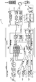
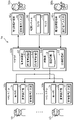
- FIG. 1A is a conceptual diagram of a VR sightseeing system according to a reference example that enables conversation with a guide.
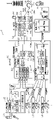
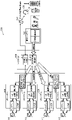
- FIG. 1B is a block diagram showing the detailed configuration of the VR sightseeing system shown in FIG. 1A.
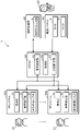
- FIG. 2A is a block diagram showing the configuration of the video display system according to the embodiment.
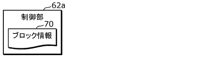
- 2B is a block diagram showing a configuration of a control unit according to Modification 1 of the video display system shown in FIG. 2A.
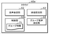
- FIG. 2C is a block diagram showing the configuration of a cloud according to modification 2 of the video display system shown in FIG. 2A.
- FIG. 2D is a block diagram showing the configuration of a video display system according to Modification 3 of the video display system shown in FIG. 2A.
- FIG. 1A is a conceptual diagram of a VR sightseeing system according to a reference example that enables conversation with a guide.
- FIG. 1B is a block diagram showing the detailed configuration of the VR sightseeing system shown in FIG. 1A.
- FIG. 2A is
- FIG. 2E is a block diagram showing the configuration of a cloud according to Modification 1 of the video display system shown in FIG. 2D.
- FIG. 2F is a block diagram showing the configuration of a cloud according to modification 2 of the video display system shown in FIG. 2D.
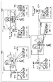
- FIG. 3 is a schematic diagram of the VR sightseeing system according to the first embodiment.
- FIG. 4 is a diagram illustrating an operation example of the VR sightseeing system according to the first embodiment;
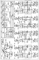
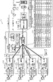
- FIG. 5 is a block diagram showing the detailed configuration of the VR sightseeing system according to the first embodiment.
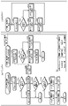
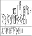
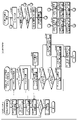
- FIG. 6 is a diagram illustrating an operation flow example of the VR sightseeing system according to the first embodiment.
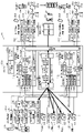
- FIG. 7 is a diagram showing a specific configuration example of the VR system of the VR sightseeing system according to the first embodiment.
- FIG. 8 is a diagram showing a specific configuration example of the VR audio conference unit included in the guide terminal of the VR sightseeing system according to the first embodiment.
- FIG. 9 is a schematic configuration diagram of a VR sightseeing system according to Modification 1 of Embodiment 1.
- FIG. 10 is a schematic configuration diagram of a VR sightseeing system according to Modification 2 of Embodiment 1.
- FIG. 11 is a diagram illustrating an operation example of the VR sightseeing system according to the second embodiment.
- FIG. 12 is a schematic diagram of the VR sightseeing system according to the second embodiment.
- FIG. 13 is a diagram illustrating an operation flow example of the VR sightseeing system according to the second embodiment.
- FIG. 14 is a diagram in which the description of problem (3) is added to the VR sightseeing system according to the reference example shown in FIG.
- FIG. 15 is a diagram illustrating an operation example of the VR sightseeing system according to the third embodiment
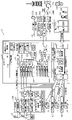
- FIG. 16 is a block diagram showing the detailed configuration of the VR sightseeing system according to the third embodiment.
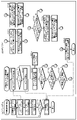
- FIG. 17 is a diagram illustrating an operation flow example of the VR sightseeing system according to the third embodiment.
- FIG. 18 is a block diagram showing the detailed configuration of the VR sightseeing system according to Modification 1 of Embodiment 3.
- FIG. 19 is a diagram in which the description of problem (4) is added to the VR sightseeing system according to the reference example shown in FIG. 1A.
- FIG. 20 is a diagram showing required specifications of the VR sightseeing system according to the fourth embodiment.
- FIG. 21 is a schematic configuration diagram of a VR sightseeing system according to the fourth embodiment.
- FIG. 22 is a diagram illustrating an example of a use case realized by the VR sightseeing system according to the fourth embodiment
- FIG. 23 is a diagram showing an example of a field of view seen by the VR system in the VR sightseeing system according to the fourth embodiment.
- FIG. 24 is a block diagram showing the detailed configuration of the VR sightseeing system according to the fourth embodiment.
- FIG. 25 is a diagram illustrating an operation flow example of the VR sightseeing system according to the fourth embodiment.
- 26 is a schematic configuration diagram of a VR sightseeing system according to Modification 1 of Embodiment 4.
- FIG. FIG. 27 is a diagram illustrating an example of a use case realized by the VR sightseeing system according to Modification 1 of Embodiment 4.
- FIG. 28 is a diagram for explaining functions of an audio switching unit included in the VR sightseeing system according to Modification 1 of Embodiment 4.
- FIG. FIG. 29 is a block diagram showing the detailed configuration of the VR sightseeing system according to Modification 1 of Embodiment 4.
- FIG. 30 is a diagram illustrating an operation flow example of the VR sightseeing system according to Modification 1 of Embodiment 4.
- FIG. 31 is a schematic configuration diagram of a VR sightseeing system according to modification 2 of embodiment 4.
- FIG. 32 is a diagram illustrating an example of a use case realized by the VR sightseeing system according to Modification 2 of Embodiment 4.
- FIG. 33 is a diagram for explaining detailed functions of a machine translation unit included in the VR sightseeing system according to Modification 2 of Embodiment 4;
- FIG. 34 is a block diagram showing the detailed configuration of the VR sightseeing system according to Modification 2 of Embodiment 4.
- FIG. 35 is a diagram illustrating an operation flow example of the VR sightseeing system according to Modification 2 of Embodiment 4.
- VR sightseeing services that realize virtual experiences such as sightseeing trips, exhibition tours, inspections, factory tours, art museums, museums, zoos, and aquariums without actually going to the place have become popular.
- Participants in VR tourism services include people with various experiences, ICT abilities, personalities, languages, etc., such as the elderly, children, and foreigners, so it is important to provide services that meet the following requirements. be.
- the VR sightseeing system uses a 360-degree video distribution system and a digital audio conference unit, and then allows VR sightseeing participants and guides to communicate in three states. , respectively, by realizing means that can be operated with a simple UI (user interface) with a single button, making it possible to provide a VR sightseeing service that anyone can easily participate in.
- a simple UI user interface
- the problems of (2) to (4) above were solved.
- the problems of (2) to (4) above were solved.
- VR tourism it is possible to realize a service with a simple UI that everyone from the elderly to children can participate in even without knowledge of ICT, so it is possible to enjoy VR tourism as if it were actual sightseeing.
- the VR sightseeing system according to the present disclosure does not necessarily have to solve all of the above four problems, and as a video display system in which anyone can easily participate, at least one of the above problems (1) to (4) Anything that solves
- FIG. 1A is a conceptual diagram of a VR sightseeing system 650 according to a reference example that enables conversation with a guide.
- the VR sightseeing system 650 by sending the video and audio (environmental sounds of the site, the voice of the guide 20, etc.) captured by the 360-degree camera at the site to each of the VR users 10 to 13, the presence of the site can be realized. Enables a pseudo-tourism experience with Note that the "VR user” is also referred to as "VR sightseeing user", “participant”, or simply "user”.
- the VR users 10 to 13 can have a two-way conversation with the guide 20 while wearing the VR systems 600 to 630, instead of listening to the explanation of the guide 20 one-sidedly. It is very important to. Therefore, in the VR sightseeing system 650 according to the reference example, as shown in FIG. Also, a function of conversing with other VR users 10 to 13 and conversing with the guide 20 is realized.
- FIG. 1B is a block diagram showing the detailed configuration of the VR sightseeing system 650 shown in FIG. 1A.
- the VR system 600 or the like includes a VR voice conference unit 605 that enables voice conversation during VR sightseeing.
- the VR audio conference unit 605 includes an A/D converter 108a that converts an audio signal output from the microphone 108 into digital audio data, an audio compression unit 108b that compresses the audio data, and a VR Mute section 108c for controlling transmission/non-transmission to the cloud 800.
- FIG. 1B is a block diagram showing the detailed configuration of the VR sightseeing system 650 shown in FIG. 1A.
- the VR system 600 or the like includes a VR voice conference unit 605 that enables voice conversation during VR sightseeing.
- the VR audio conference unit 605 includes an A/D converter 108a that converts an audio signal output from the microphone 108 into digital audio data, an audio compression unit 108b that compresses the audio data, and a VR Mute section 108c for controlling transmission/non-transmission to
- the VR audio conference unit 810 provided in the VR cloud 800 includes audio decoding units 314a to 314d that decode audio data transmitted from the VR system 600 and the like, and compressed audio transmitted from the smartphone 710 used by the guide 20.
- An audio decoding unit 316 that decodes data; an audio mixing unit 313 that mixes the audio data from the audio decoding units 314a to 314d and the audio data from the audio decoding unit 316 to generate synthesized audio data;
- An audio compression unit 317 that compresses audio data and transmits it to the smartphone 710 of the guide 20 is provided.
- the 360-degree video distribution unit 820 provided in the VR cloud 800 receives the 360-degree video transmitted from the observation system 700, separates it into video data and audio data, and decodes the separated audio data.
- an audio decoding unit 322 for decoding receives the 360-degree video transmitted from the observation system 700, separates it into video data and audio data, and decodes the separated audio data.
- an audio decoding unit 322 for decoding receives the 360-degree video transmitted from the observation system 700, separates it into video data and audio data, and decodes the separated audio data.
- an audio decoding unit 322 for decoding
- an audio mixing unit 323 for mixing the decoded audio data and the synthesized audio data sent from the VR audio conference unit 810
- an audio compression unit 324 for compressing the mixed audio data
- An AV synthesizing unit 325 is provided for synthesizing the compressed audio data and the video data separated by the AV separating unit 321 and delivering a 360-degree video to the VR system 600 or the like.
- the smartphone 710 which is a guide audio conference terminal, has hardware and an application (APP) that functions as the VR audio conference unit 750.
- the audio signal output from the microphone of the headset 720 is digitally , an audio compression unit 213b for compressing the audio data, a mute unit 213c for controlling whether or not to transmit the compressed audio data to the VR cloud 800, and the VR cloud Audio decoder 214a receives and decodes the synthesized speech data transmitted from 800, and D/A converter 214b converts the decoded synthesized speech data into analog speech signals and outputs them to speakers of headset 720. Consists of
- the observation system 700 includes an imaging unit 202 that controls a camera 203 for 360-degree imaging and acquires signals from the camera 203 and a remote controller 204, and a VR cloud that uses the signals acquired by the imaging unit 202 as 360-degree images. and a communication unit 201 for transmitting to 800 .
- a video distribution system including the 360-degree video distribution unit 820 is combined with a general net conference system to realize a conversation between the VR users 10 to 13 and the guide 20.
- the following functions are added (1) to (3).
- a smartphone 710 which is a voice conference terminal for guiding, is connected to the VR voice conference unit 810 of the VR cloud 800 from a headset 720 equipped with a microphone, earphones, etc. via an ICT device such as a smartphone.
- the position of the mute unit 108c is not limited to that shown in the figure as long as it can mute the sound captured by the microphone 108 before being mixed by the audio mixing unit 313.
- the Mute unit 108c may be located between the A/D conversion unit 108a and the Audio compression unit 108b or between the microphone 108 and the A/D conversion unit 108a.
- VR sightseeing users In the case of online conference systems such as Zoom (registered trademark) and Teams (registered trademark), it is used for business, and users can expect a certain level of ICT skills, so operations such as setting and canceling mute by themselves are not possible. It is possible.
- VR sightseeing users may be users of a wide range of age groups from the elderly to children, occupations, educational levels, etc., and it cannot be expected that all participants will have ICT skills. Therefore, the following problems may occur.
- each VR user should use the mute function of their own VR system when they are not speaking.
- the VR sightseeing system according to the reference example has the following four problems (1) to (4) to be solved.
- VR tourism users are different from users of net conference systems used for work, education, etc., and are attended by people of various ages and with different levels of understanding of ICT technology. Also, wearing VR goggles and entering the VR space blocks the view. Therefore, a user interface that is easy to operate using a controller or the like and satisfies the following simple conditions is required. It is also necessary that the user does not need to learn the concept or operation of mute. It is also necessary that the VR experience does not deteriorate even if people who cannot learn how to operate it, who have forgotten how to operate it, or who do not follow the rules participate. Furthermore, it is important to be able to easily explain the operation of the VR system before the VR experience.
- the main task of the guide 20 is to explain, and they cannot operate the system like the host of the net conference system.
- a very simple user interface is required for the guide 20 so that the user can concentrate on the instructional work.
- FIG. 2A is a block diagram showing the configuration of the image display system 1 according to the embodiment.
- the video display system 1 is a system that provides a service for experiencing VR (virtual reality), and includes VR systems 30a to 30b used by the participants 10 to 13, an explainer terminal 40, an observation system 50, and a cloud 60. Prepare.
- the VR systems 30a-30b, the explainer terminal 40, and the observation system 50 are connected to the cloud 60 via a communication network.
- Each of the VR systems 30a to 30b has a display unit 31 that displays a VR space, which is video for VR, to the participants 10 to 13 who participate in the experience, and performs audio input/output with the participants 10 to 13. It has an audio processing unit 32 .
- the explainer terminal 40 is a terminal that performs voice input/output with the explainer 20 who gives an explanation for the experience to the participants 10 to 13 in the VR space, and indicates whether or not to accept questions. It has an explainer input unit 41 that accepts an operation from 20 .
- the observation system 50 is a system that generates a 360-degree video by photographing the real world and transmits it to the video distribution unit 63 of the cloud 60, and has a camera 51 and a microphone 52 that acquires the voice of the explainer 20.
- the cloud 60 is a computer on a communication network, and a video distribution unit 63 that distributes 360-degree video for generating a VR space to the VR systems 30a to 30b, VR systems 30a to 30b, and the explainer terminal 40.
- control unit 62 selectively selects a first state in which the participants 10 to 13 cannot ask questions to the explainer 20, a second state in which questions can be asked, and a third state in which questions are asked.
- the VR systems 30a and 30b are controlled so that the operating modes to be taken are managed and information specifying the operating modes is displayed on the display unit 31.
- the participants 10 to 13 can determine their own states according to the information specifying the operation mode displayed on the display unit 31: the first state in which questions cannot be asked; the second state in which questions can be asked; It is possible to immediately know which of the third states is being performed, and the operation for asking questions to the explainer 20 is simplified. need to have a simple user interface to make the service available) is solved.
- the video distribution unit 63 of the cloud 60 may read 360-degree video from a storage previously created and held by live action, CG, etc., and distribute it to the VR systems 30a-30b.
- control unit 62 does not need to be provided in one computer that constitutes the cloud 60, and all of the control unit 62 is installed in other devices such as a plurality of computers, the VR systems 30a to 30b, and the presenter terminal 40. Or a part may be provided. That is, the control unit 62 may be divided into a plurality of functional modules and distributed to a plurality of devices.
- the control unit 62 displays an image indicating the first state on the display units 31 of the plurality of VR systems 30a to 30b.
- presenter input unit 41 displays a first
- an operation to set the second state that is, a question-accepting state
- an image showing the second state is displayed on the display units 31 of the plurality of VR systems 30a to 30b to set the second state, that is, a state in which questions can be asked
- Multiple VR systems 30a-30b may be controlled to place audio input from multiple participants 10-13 in a first state, ie, mute the audio input.
- the presenter 20 can control whether or not questions are permitted for the plurality of participants 10 to 13 with a simple operation using the presenter input unit 41 .
- the control unit 62 controls the participant input unit that has received the operation.
- the operation mode is in the second state
- information specifying the third state is displayed on the display unit 31 instead of the second state, and voice input from the participant is performed.
- the VR system 30a or the like may be controlled so that the third state is achieved by canceling the mute of the VR system 30a.
- the participants 10 to 13 can ask the explainer 20 a question with a simple operation using the participant input section 33 .
- the control unit 62 controls the VR system 30a and the like so as to unmute the audio input from the participant 10 and the like, that is, to put it in the third state
- the control unit 62 controls other VR systems other than the VR system 30a and the like.
- the VR system 30a etc. is set to the first state by displaying an image indicating the first state on the display unit 31 and muting the voice input from the corresponding participant 13 etc. may be controlled.
- the explainer input unit 41 may be a single button that accepts an operation indicating acceptance of a question and an operation indicating not accepting a question. As a result, the presenter 20 can switch between a question-accepting state and a question-not-accepting state by a simple operation using one button.
- the participant input unit 33 may be a single button that accepts a request to ask a question, an operation indicating that the question is being asked, and an operation indicating that the question has been completed. .
- the participants 10 to 13 can start asking questions to the explainer 20 by a simple operation using one button.
- the voice conversation unit 61 uses the explainer 20's voice acquired by the microphone 52 of the observation system 50 to Voice conversation between 13 and presenter 20 may be supported.
- the presenter 20 can use the microphone 52 of the observation system 50 to explain sightseeing information and answer questions from the participants 10-13.
- FIG. 2B is a block diagram showing the configuration of the control unit 62a according to Modification 1 of the video display system 1 shown in FIG. 2A.
- the control unit 62a has block information 70 including permission/denial information indicating whether or not to block questions to the presenter 20 for each of the plurality of participants 10 to 13, and based on the block information 70 Then, for the participants 10, etc. whose permission/denial information indicates blocking, an image showing the first state is displayed on the display unit 31 of the VR system 30a, etc. corresponding to the participants 10, etc., and The VR system 30a and the like are controlled so that the first state is achieved by muting the audio input.
- FIG. 2C is a block diagram showing the configuration of the cloud 60a according to Modification 2 of the video display system 1 shown in FIG. 2A.
- the cloud 60 a includes a voice conversation unit 61 , a control unit 62 b, a video distribution unit 63 and a group voice conversation unit 64 .
- the group voice conversation unit 64 supports group voice conversations between two or more participants 10 selected from a plurality of participants 10-13.
- the control unit 62b has group information 71 including belonging information indicating whether or not each of the plurality of participants 10 to 13 belongs to a predetermined group.
- the group voice conversation unit 64 is controlled so as to support the group voice conversation only for the participants 10, etc. of the group. This solves problem (3) mentioned above (the need to be able to support private conversations between friends traveling together).
- control unit 62b controls the group voice conversation when the operation mode of the corresponding VR system 30a or the like of any of the plurality of participants 10 or the like belonging to the same group is in the first state or the second state.
- the group voice conversation unit 64 is controlled so as to support .
- the control unit 62b controls the group voice conversation. Suspend support, display an image showing the first state on the display unit 31 of the corresponding VR system 30b, etc. for all participants 13, etc. other than the participant 10, etc., and control the VR system 30a-30b to mute the audio input of As a result, when one participant starts asking a question to the explainer 20 during a group conversation, the other participants can listen to the question.
- control unit 62b controls the volume of at least one of the voice from the explainer 20 to a plurality of participants 10 belonging to the same group and the voice of the group voice conversation.
- a plurality of VR systems 30a etc. corresponding to a plurality of participants 10 etc. belonging to the same group may be controlled so as to coordinate.
- participants in the group voice conversation can listen to both the group voice conversation and the explanation by the explainer 20 in a mixed form.
- FIG. 2D is a block diagram showing the configuration of a video display system 1a according to Modification 3 of the video display system 1 shown in FIG. 2A.
- the image display system 1a includes a first explainer terminal 40a and a second explainer terminal 40b instead of the explainer terminal 40 in the image display system 1 shown in FIG. 2A, and a cloud 60b instead of the cloud 60.
- FIG. 1a includes a first explainer terminal 40a and a second explainer terminal 40b instead of the explainer terminal 40 in the image display system 1 shown in FIG. 2A, and a cloud 60b instead of the cloud 60.
- the first explainer terminal 40a is a terminal that performs voice input/output with the first explainer 20a who gives explanations in the first language.
- the second explainer terminal 40b is a terminal that performs voice input/output with the second explainer 20b who gives explanations in the second language.
- the cloud 60b includes a voice conversation unit 61, a control unit 62c, and a video distribution unit 63.
- the voice conversation unit 61 includes a first voice conversation unit 61a that supports voice conversation between the participants 10 to 13 and the first explainer 20a via the plurality of VR systems 30a to 30b and the first explainer terminal 40a; and a second voice conversation unit 61b for supporting voice conversation between the participants 10 to 13 and the second presenter 20b via the VR systems 30a to 30b and the second presenter terminal 40b.
- the control unit 62c has language information 72 that associates the language of explanation desired for each of the plurality of participants 10 to 13, and based on the language information 72, the participant 10 etc. associated with the first language.
- the first voice conversation unit 61a supports the voice conversation between the participant 10 and the first presenter 20a
- the second voice conversation unit 61b supports the participant 13 and the like associated with the second language.
- the first voice conversation unit 61a and the second voice conversation unit 61b are controlled so as to support the voice conversation between the participant 13 and the second presenter 20b.
- the second explainer 20b may be a simultaneous interpreter for the first language and the second language.
- the first voice conversation unit 61a further outputs the voice from the first explainer 20a to the second explainer 20b.
- a video display system that can accommodate simultaneous interpreters is realized.
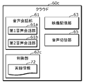
- FIG. 2E is a block diagram showing the configuration of the cloud 60c according to Modification 1 of the video display system 1a shown in FIG. 2D.
- the cloud 60 c includes an audio conversation unit 61 , a control unit 62 c, a video distribution unit 63 and an audio switching unit 65 .
- the audio switching unit 65 outputs the audio from the simultaneous interpreter to the participants 10 etc. associated with the second language, and outputs the audio to the first explainer 20a and the participants 13 etc. associated with the first language. Switch output.
- the simultaneous interpreter 20b is a simultaneous interpreter
- the simultaneous interpreter can switch between speaking to the participants and speaking to the first explainer 20a who speaks the first language, which is convenient. performance is improved.
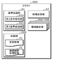
- FIG. 2F is a block diagram showing the configuration of a cloud 60d according to modification 2 of the video display system 1a shown in FIG. 2D.
- the cloud 60d includes a voice conversation unit 61, a control unit 62d, a video distribution unit 63, and machine translation units 66a-66b.
- the machine translation units 66a-66b perform machine translation between two different languages (first language, second language, etc.).
- the control unit 62d has language information 72 that associates the language of explanation desired for each of the plurality of participants 10 to 13, and based on the language information 72, the participant 10 etc. associated with the first language. , the participants 10, etc. and the explainer 20 have a voice conversation without going through the machine translation units 66a-66b, and the participants 13, etc. associated with the second language participate through the machine translation unit 66a etc.
- the machine translation unit 66a and the like are controlled so that the person 13 and the explainer 20 have a voice conversation. This makes it possible to support multiple languages through machine translation.
- control unit 62 has machine translation management information 73 indicating two languages handled by a plurality of machine translation units 66a to 66b, and based on the language information 72 and the machine translation management information 73, each participant 10 to 13 Then, a machine translation unit that translates between the language associated with the participants 10 to 13 and the first language used by the guide is selected from a plurality of machine translation units 66a to 66b, and the selected machine translation unit 66a to A plurality of machine translation units 66a-66b may be controlled so that participants 10-13 and presenter 20 have voice conversations through 66b. This enables support for an extremely large number of languages, corresponding to multiple different types of machine translation.
- the video display method according to the present disclosure is a video display method by a video display system 1 that provides a service for experiencing VR (virtual reality).
- It includes control steps for controlling the VR systems 30a-30b to display information specifying the mode on the display unit 31 (FIG. 6). More specifically, in the control step, the operation mode corresponding to each of the plurality of VR systems 30a-30b is managed, and information specifying the operation mode is displayed on the display unit 31 of the corresponding VR system 30a-30b. , controls a plurality of VR systems 30a-30b (FIGS. 6, 2A).
- the participants 10 to 13 can determine their own states according to the information specifying the operation mode displayed on the display unit 31: the first state in which questions cannot be asked; the second state in which questions can be asked; It is possible to immediately know which of the third states is being performed, and the operation for asking questions to the explainer 20 is simplified. need to have a simple user interface to make the service available) is solved.
- the permission/denial information indicates that the participation is blocked.
- an image showing the first state is displayed on the display unit 31 of the VR system 30a to 30b corresponding to the participants 10 to 13, and voice input from the participants 10 to 13 is muted.
- the VR systems 30a-30b are controlled to be in the first state (FIGS. 13 and 2B).
- group information 71 including belonging information indicating whether or not each of the plurality of participants 10 to 13 belongs to a predetermined group is provided.
- the group voice conversation unit 64 is controlled so as to support group voice conversations for a plurality of participants 10-13 (FIGS. 13 and 2C). This solves problem (3) mentioned above (the need to be able to support private conversations between friends traveling together).
- the participants 10 to 13 associated with the first language are The voice conversation unit 61a supports voice conversation between the participants 10 to 13 and the first presenter 20a. 13 and the second explainer 20b, the first voice conversation unit 61a and the second voice conversation unit 61b are controlled (FIGS. 25 and 2D). This solves the above-mentioned problem (4) (it is necessary to support multiple languages and multiple guides for VR sightseeing participants in order to deal with foreign travelers and foreigners).
- the participants 10 to 13 associated with the first language are machine-translated based on the language information 72 that associates the language of the explanation desired for each of the plurality of participants 10 to 13.
- the participants 10 to 13 and the presenter 20 have a voice conversation without going through the units 66a to 66b, and the participants 10 to 13 associated with the second language are translated through the machine translation units 66a to 66b.
- the machine translation units 66a-66b are controlled so that 13 and the presenter 20 have voice conversation (FIGS. 35 and 2F).
- Examples 1 to 4 for solving the above problems (1) to (4) will be described below as specific examples of the embodiment. Each example will be described as an example in which the video display system according to the embodiment is applied to a VR sightseeing system.
- Example 1 First, Example 1 will be described as a specific example for solving the above problem (1) (it is necessary to have a simple user interface that allows various participants to use the VR sightseeing service).
- FIG. 3 is a schematic diagram of the VR sightseeing system 2 according to the first embodiment.
- the VR tourism system 2 includes: A) VR systems 100, 110, 120 and 130 for the VR users 10 to 13 to experience VR tourism services; 360-degree video distribution unit 320 that distributes 360-degree video for generating the VR space in 130; and D) a guide terminal 210 consisting of a smartphone 210, a headset 220, and a guide remote control 230 for the guide 20 to have a voice conversation with the VR users 10 to 13. etc.
- the VR system 100 (110, 120, and 130) includes a display 101 (111, 121, and 131), an input unit 102 (112, 122, and 132) that receives operations, and a communication unit 104 that communicates with the VR cloud. (114, 124 and 134), and a VR space generator 103 (113, 123 and 133) for generating a VR space to be displayed on the display 101 (111, 121 and 131).
- the VR space generation unit 103 (113, 123 and 133) and the display 101 (111, 121 and 131) are examples of the display unit 31 in the embodiment
- the input unit 102 (110, 120 and 130) are examples of the display unit 31 in the embodiment. It is an example of the input part 33 for participants in a form. Note that the illustration of the audio processing unit 32 in the embodiment is omitted in this schematic configuration diagram.
- the VR cloud 300 includes a VR audio conference unit 310 having a conversation control unit 311 and an audio processing unit 312, and a 360-degree video distribution unit 320.
- the VR audio conference unit 310 is an example of the audio conversation unit 61 in the embodiment
- the 360-degree video distribution unit 320 is an example of the video distribution unit 63 in the embodiment
- the conversation control unit 311 is an example of the video distribution unit 63 in the embodiment. is an example of the control unit 62 in .
- the observation system 200 includes a communication unit 201, an imaging unit 202, a camera 203, a remote controller 204, and a microphone 205.
- Camera 203 is an example of camera 51 in the embodiment
- microphone 205 is an example of microphone 52 in the embodiment.
- the guide terminal 210 or the like is an example of the explainer terminal 40 in the embodiment, and is composed of a smartphone 210, a headset 220, and a guide remote controller 230, which is an example of the explainer input unit 41 in the embodiment. be done.
- the guide instruction generation unit 211 has a function of acquiring an instruction of the guide 20 from the guide remote control 230 and outputting it to the VR audio conference unit 310.
- the presenter input unit 41 This is an example of the function of acquiring the instruction of the guide 20 from.
- the guide 20 uses the guide instruction generation unit 211 in the guide terminal 210 or the like to operate the conversation control unit 311 in the VR cloud 300, so that the VR systems 100, 110 of each VR user 10 to 13 , 120 and 130 audio/display control (mute function, guidance display, etc.).
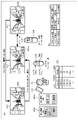
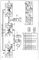
- FIG. 4 is a diagram showing an operation example of the VR sightseeing system 2 according to the first embodiment. More specifically, (a) of FIG. 4 shows display examples in the VR systems 100, 110, 120 and 130, display examples 240a and 240b of the guide 20 by the voice control application on the smartphone 210, and an operation example of the guide remote controller 230. , an operation example of the VR remote controller 106 by the VR user 10 or the like.
- FIG. 4 shows an operation mode description table 410 showing an example of operation mode management by the conversation control unit 311 . That is, when the "guidance” is “question not allowed”, “question not allowed” 400a is displayed at the lower right of the screen display example 400 of the VR system ("VR display state” is "question not allowed”).
- VR system mute function is “muted”, i.e., the first state
- the “guide instruction” is “questionable” 401a is displayed in the lower right of the screen display example 401 of the VR system (the display mode of the "VR display state” is the "questionable” display mode, that is, the second state), the VR user is being muted (“VR system mute function” is “Mute”), and “Questioning” 402a is displayed at the lower right of the screen display example 402 of the VR system (“VR display state” is In the “questioning” display mode (ie, the third state), the VR user is in an unmuted state (“VR system mute function” is “unmuted”).
- the three guidance display modes in the VR systems 100, 110, 120 and 130, the guide 20, the VR user 10, etc. are all realized by a simple one-button UI. , the following four things are realized.
- the guide 20 When the guide 20 does not want to be asked a question (that is, does not want to be disturbed in the explanation), the guide 20 simply operates the "no question” instruction at any time (even if the question is being asked), and the VR user 10 ⁇ 13 can be disabled from asking questions. Further, when accepting questions, it is possible to enable questions to the VR users 10 to 13 simply by instructing "questions allowed". Since both operations can be performed with a simple operation of one button such as a toggle button, the guide 20 can concentrate on the explanation.
- the VR users 10 to 13 can easily enjoy conversation with the guide 20 by operating a single button.
- the guide 20 can easily control the VR systems 100, 110, 120 and 130 with a single button operation, and can smoothly explain without disturbing the VR users 10-13.
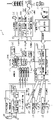
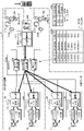
- FIG. 5 is a block diagram showing the detailed configuration of the VR sightseeing system 2 according to the first embodiment.
- the VR sightseeing system 2 is the configuration example of the VR sightseeing system 650 according to the reference example shown in FIG.
- a conversation control unit 107 and a guidance display control unit 109 are added to the VR audio conference units 105 of the systems 100, 110, 120, and 130, and an input unit 212 and a guide An instruction generator 211 is added.
- an input unit 212 that receives user input, and a guide instruction that transmits the instruction content of the guide 20 to the VR audio conference unit 310 in the VR cloud 300 based on the input and a generation unit 211 .
- it receives instructions from the guide 20 sent from the guide terminal 210 or the like into the VR cloud 300, and records the contents of the instructions in the guide instruction recording unit 315.
- a conversation control unit 107 for generating control instructions for controlling the audio conferencing unit 105 and transmitting them to the VR systems 100 , 110 , 120 and 130 .
- the functions shown in FIG. 4 are realized by executing the algorithm of the operation flow example of the VR sightseeing system 2 according to the first embodiment shown in FIG. 6 below.
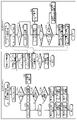
- FIG. 6 is a diagram showing an operation flow example (that is, a specific example of a video display method) of the VR sightseeing system 2 according to the first embodiment. More specifically, FIG. 6(a) shows the operational flow of the VR systems 100, 110, 120 and 130, and FIG. 6(b) shows the same operational mode description as FIG. 4(b) for reference. Table 410 is shown, and (c) of FIG. 6 shows the operation flow of VR cloud 300 .
- the VR cloud 300 receives a “guide instruction” from the APP of the smartphone 210, the guide remote controller 230, etc. via the input unit 212 and the guide instruction generation unit 211 of the guide terminal 210, etc.
- "Instruction” transition to “questionable”, transition to “questionable” as transition of operation mode
- S10 transition of operation mode
- the conversation control unit 311 determines the received "guide instruction” (S11) and divides it into the following two processes. That is, if the "guidance instruction" is "questionable” (Y in S11), the instruction is set to “questionable” (S13); N), and set the instruction to "no questions allowed” (S12).
- the conversation control unit 311 notifies all the VR systems 100, 110, 120 and 130 that the guide 20 has issued a new instruction together with the contents of the instruction (S14), and returns to step S10.
- each of the VR systems 100, 110, 120 and 130 performs the main processing of the VR sightseeing distribution service, but as shown in FIG. If there is S24), the interrupt process is performed and the process returns to the main process. If there is no interrupt processing, the reception processing in the VR sightseeing service is continued until the VR sightseeing distribution service ends.
- the main processing of the VR systems 100, 110, 120 and 130 is processing in which the VR systems 100, 110, 120 and 130 provide the VR users 10 to 13 with a VR space for VR sightseeing.
- the VR systems 100, 110, 120 and 130 After receiving the 360-degree video sent from the distribution unit 320, separating the received 360-degree video into video data and audio data, and decoding the separated audio data, depending on the position and orientation of the VR observation system 200
- the separated video data is decoded, it is mapped to a 360-degree spherical video, and video clipping is performed depending on the position and orientation of the VR observation system 200. This is the process of outputting to the display as an image.
- the first interrupt process is the user input interrupt process of the VR systems 100, 110, 120 and 130.
- the conversation control unit 107 receives a VR user input from the VR remote controller 106 or the like (S30), and if the received VR user input is a "questioning" request (Y in S31), the information in the guide instruction recording unit 315 is Refer (S33).
- the process is terminated. If the display mode is "questionable”, that is, in the second state (N in S36), the guidance display control unit 109 changes the display mode to "questioning" (S37), and the mute unit 108c cancels mute. It is set (S38), that is, the third state is set, and the process ends.
- the guidance display control unit 109 changes the display mode to The state is changed to "questionable” (S39), and the Mute unit 108c sets the state to Mute, ie, the second state (S40), and terminates the process.
- the conversation control unit 107 processes the VR user input (S32) and ends the process.
- the second interrupt process is the interrupt process from the VR cloud 300.
- the conversation control unit 311 records the guide instruction received from the VR cloud 300 in the guide instruction recording unit 315 (S20).
- the guidance display control unit 109 is caused to set the display mode to "questions allowed", that is, the second state (S23), and the process ends.
- the guidance instruction is "no questions asked” (N at S21)
- the guidance display control unit 109 sets the display mode to "no questions asked” (S22)
- the mute unit 108c sets to mute (S24), That is, the first state is set, and the process ends.
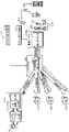
- FIG. 7 is a diagram showing a specific configuration example of the VR systems 100, 110, 120 and 130 of the VR sightseeing system 2 according to the first embodiment.
- the VR systems 100, 110, 120 and 130 consist of a computer or smartphone (computer/smartphone 160) and an HMD (head mounted display) or VR glasses (HMD/VR glasses 140) connected thereto. be done.
- the VR systems 100, 110, 120 and 130 may be realized by the HMD/VR glasses 140 alone. In that case, the functions of both the CPU and GPU will be integrated, and the peripheral functions will also be integrated.
- the computer/smartphone 160 mainly includes a high-speed communication element 163 compatible with WiFi (registered trademark) or Ethernet (registered trademark) for connecting to the VR systems 100, 110, 120 and 130, video data and graphics.
- a GPU (Graphics Processing Unit) 165 that mainly processes software, a CPU (Central Processing Unit) 170 that performs general data processing and overall control of the computer/smartphone 160, and stores programs for operating the CPU 170 and GPU 165
- a non-volatile memory 167 such as a hard disk or flash memory for operation, a RAM 166 used to store data for the operation of the CPU 170 or GPU 165, a power control element 169 for supplying power to the power switch 168 and each part, HMD/VR glasses 140 AV output terminal 161 for outputting video and audio signals to, I / F such as USB (Universal Serial Bus) 162 for controlling HMD / VR glasses 140 and acquiring data from there, RAM 166 and non-volatile memory 167 and accessed by the CPU 1
- the CPU 170 has, as functions exerted by executing a program, a multiplexing unit 170a that multiplexes video data and audio data, a separation unit 170b that separates video data and audio data from the received 360-degree video, and a separation unit 170b. It has an audio decoding unit 170c that decodes the audio data obtained, and an audio reproduction control unit 170d that controls reproduction of the decoded audio data.
- the GPU 165 receives the motion/position data generated by the motion/position detection unit 165a of the HMD/VR glasses 140 and detects the motion/position of the VR user as a function exhibited by the execution of the program. , a VR control unit 165b that issues an instruction to generate a VR space based on the detected motion and position of the VR user; A guidance display generation unit 165d for instructing display generation of guidance such as "questionable” and “questioning", a graphics generation unit 165e for generating guidance graphics according to the instructions, and a VR space from the VR control unit 165b. Based on the generation instruction, the video data decoded by the VR video decoding unit 165c and the graphics generated by the graphics generation unit are synthesized, and the VR display control unit outputs the VR video to the HMD/VR glasses 140. 165f.
- the bus configuration may also differ from this example, but there is no difference in the functional configuration and operation.
- the AV output terminal 161 and the USB 162 can be replaced by an I/F such as USB_TypeC (registered trademark) as a high-speed bidirectional I/F.
- the HMD/VR glasses 140 are also connected with the same I/F or connected with a converter that converts the I/F.
- the CPU 170 or GPU 165 performs appropriate video compression in order to compress the amount of data by appropriate compression, and the VR video is sent to the HMD/VR glasses 140 via USB 162. do.
- the HMD/VR glasses 140 in the VR systems 100, 110, 120 and 130 mainly consist of a microphone 157a for inputting voice, a microphone amplifier 157b, and an ADC (A/D converter) 157c. , speaker 158c, headphone terminal 158d, amplifier 158b, DAC (D/A converter) 158a, two sets of lenses 153a and 153b and display elements 152a and 152b for the user to view VR images.
- ADC A/D converter
- a motion/position sensor 141 consisting of a VR display unit, a gyro sensor, a motion/position detection unit and an orientation detection unit including a gyro sensor, a camera or an ultrasonic microphone, and a Bluetooth (registered trademark) for communicating with a controller (not shown).
- RAM 155 RAM 155, SD card (registered trademark), GPU 151, CPU 156, memory bus for exchanging data with memory, CPU 156, GPU 151, wireless communication device 148, receiving video and audio signals from computer/smartphone 160 AV input terminal 146 for receiving control signals from the computer/smartphone 160, I / F such as USB 147 for sending video and audio signals, movement and position data, mainly audio compression (audio compression unit 156a), switches, power supply, etc., CPU 156 that controls the entire HMD/VR glasses 140, image display processing unit 151b that mainly adjusts images on the VR display unit, and information from the movement/position sensor 141 to the computer.
- I / F such as USB 147 for sending video and audio signals, movement and position data, mainly audio compression (audio compression unit 156a), switches, power supply, etc.
- CPU 156 that controls the entire HMD/VR glasses 140, image display processing unit 151b that mainly adjusts images on the VR display unit, and information from the movement/position sensor 141
- /GPU 151 having a motion/position detection unit 151a that corrects/shapes motion/position information sent to the smartphone 160, EEPROM 154 for storing programs and data for operating the CPU 156 and GPU 151, and data during operation of the CPU 156 and GPU 151 RAM 155 for storing, CPU 156, GPU 151, memory bus for connecting RAM 155 and EEPROM 154, CPU 156, GPU 151, USB 147, audio input unit, audio output unit, and wireless communication device 148 are connected to control and exchange data.
- an I/O bus for controlling and exchanging low-speed data including an audio input unit, an audio output unit, a VR shooting camera, etc., and several buses connecting each bus It is composed of a conversion unit 150 .
- the HMD/VR glasses 140 can be connected to the VR remote controller 106 via BLE (Bluetooth Low Energy; registered trademark) 149, and can be used when the VR users 10 to 13 want to have a conversation with the guide 20. An operation to request a "question" is possible.
- BLE Bluetooth Low Energy; registered trademark
- the video data from the AV input terminal 146 has a large amount of data and is high speed, it is illustrated that the video data is directly taken into the GPU 151 if the system bus does not have a sufficient speed.
- the video information captured by the camera of the motion/position sensor 141 is sent to the display elements 152a and 152b as information for the VR user to check the surroundings of the HMD/VR glasses 140, or to the computer/smartphone 160 via the USB 147. It may be sent to monitor whether the user is in a dangerous situation.
- the power supply control element 145 receives power supply from the USB 147 or the AV input terminal 146, stabilizes the voltage, manages the battery capacity, etc., and supplies power to all components (not shown).
- the battery 144 may be provided internally or externally, and the battery 144 may be connected to the power control element 145 .
- the state of the buttons and cursor of the controller (not shown) is acquired by the CPU 156 through the wireless communication device 148 and used for button operations, movements, and application operations in the VR space.
- the position and orientation of the controller are detected by the camera or ultrasonic sensor of the motion/position sensor 141, and after appropriate processing is performed by the motion/position sensor 141, are used for control by the CPU 156, and are transmitted via the USB 147. and sent to the computer/smartphone 160 and used for drawing graphics and image processing executed by the program executed by the CPU 156 or by the GPU 151 .
- FIG. 8 is a diagram showing a specific configuration example of the VR audio conference unit 250 included in the guide terminal 210 and the like of the VR sightseeing system 2 according to the first embodiment.
- the VR audio conference unit 250 is a communication means with the VR cloud 300 (carrier communication such as 5G, or a terminal with a communication function with the VR cloud 300 such as a PC or smartphone 210 using Wi-Fi (registered trademark) ), an audio interface 215 for connecting to an external device that performs voice input/output such as a microphone 216 and a speaker 217, and an A/D that converts analog voice to digital data or vice versa A converter 213a and a D/A converter 214b, an audio compression unit 213b and an audio decoding unit 214a for compressing and decoding digital audio data, and a mute unit 213c for temporarily not sending the audio signal from the microphone 216. and a guide instruction generator 211 that converts the input into a guide instruction and sends it to the VR cloud 300 .
- carrier communication such as
- the guide terminal 210 and the like are a communication unit/headset CODEC 211a that communicates with the external headset 220, the guide remote controller 230 and the like using power-saving communication such as BLE (registered trademark), and input according to the communication. It has an input processing unit 211 b that gives instructions and outputs them to the guide instruction generation unit 211 .
- BLE registered trademark
- a dedicated terminal may be used as the guide terminal 210 or the like, but since it can be easily implemented with the smartphone 210 and the APP of the smartphone 210, it is implemented as an APP on the smartphone 210 (for company or private use) possessed by the guide 20. good too.
- using the guide remote controller 230 connected by low power consumption communication such as BLE (registered trademark) of the smartphone 210 allows easier operation, and the fact that the user is operating is VR. This is more preferable because it is unknown to the users 10-13 as well. If the guide remote control 230 is used, it can be operated by simply blind-pushing the button of the guide remote control 230 held in the hand during the explanation.
- the VR sightseeing system 2 realizes the simple user interface shown in FIG. 4 and solves the above problem (1).
- FIG. 9 is a schematic configuration diagram of a VR sightseeing system 2a according to Modification 1 of Embodiment 1.
- FIG. The VR sightseeing system 2a is a system obtained by applying the VR sightseeing system 2 according to the first embodiment to a VR sightseeing system having a "VR motion sickness prevention function" and a VR sightseeing system having a "lost child prevention function.”
- a VR sightseeing system with a "VR motion sickness prevention function” is a VR sightseeing system with the following functions.
- a VR sightseeing system with a "VR motion sickness prevention function” can avoid VR motion sickness that accompanies the movement of a 360-degree camera taken in VR tourism, etc., from the VR observation system, in addition to 360-degree video, metadata (Start time and direction of camera movement and panning for shooting 360-degree video) is sent to the VR system, and the VR system provides a visual effect that appropriately informs the viewer of the movement immediately before and during the camera movement. (on-screen display, etc.) and non-visual effects (sound, controller vibration, etc.) to encourage viewers to prepare and prevent them from feeling dizzy. By displaying , it has a function to avoid (reduce) VR sickness.
- a VR tourism system with a "lost child prevention function” is a VR tourism system with the following functions.
- a VR tourism system with a "lost child prevention function” can provide VR users with information about the guide by sending metadata including triggers generated by a tour guide (leader, explainer) to the VR system. It has a function to prevent the user from getting lost by showing visual guidance of the position and visual guidance indicating the position of the object specified (explained) in the 3D space by video, audio, vibration, etc.
- the VR sightseeing system 2a includes VR systems 100, 110, 120 and 130, a VR cloud 300a, an observation system 200a, and guide terminals (smartphone 210, guide remote control 230).
- the guide terminal 210 and the like send the acquired metadata additional information 219a and 219b to the VR cloud 300a and the observation system 200a, respectively.
- the observation system 200a has a camera 203 mounted on a vehicle 206 for acquiring 360-degree images, a remote controller 204, an imaging unit 202, and a communication unit 201, and metadata additional information 219b received from a guide terminal 210 or the like. and the 360-degree video are transmitted to the VR cloud 300a.
- the VR cloud 300a has a 360-degree video distribution unit 320a that distributes the metadata additional information 219a received from the guide terminal 210 and the like and the 360-degree video received from the observation system 200a to the VR systems 100, 110, 120 and 130. have.
- the VR space generation unit 103 changes the display based on the metadata received from the VR cloud 300a, thereby exhibiting the "VR motion sickness prevention function" and the "lost child prevention function.” .
- additional information on which metadata is based is acquired by various methods (start time and movement direction of camera movement and panning for shooting 360-degree video, etc.). and sent to each VR system 100, 110, 120 and 130 via the VR cloud 300a. Based on this metadata, the VR systems 100, 110, 120, and 130 generate additional information when reproducing the VR space using the 360-degree video, thereby preventing VR sickness and providing appropriate guidance. present information.
- the smartphone 210 having functions such as GPS, IMU (inertial measurement unit), camera, etc., as the guide terminal, (1) the location information, acceleration information, etc. of the smartphone 210 are used to generate metadata. (2) Metadata using location information, acceleration information, etc. of the smartphone 210; It is possible to do two things: take data useful for production, send it to the VR cloud 300a, and combine it with the metadata coming from the observation system 200a to create metadata in the VR cloud 300a.
- a movement start/stop button or the like is added to the guide remote controller 230 that can communicate with the smartphone 210 via BLE (registered trademark) or the like. It is also possible to improve the accuracy of detection, etc., and generate more appropriate metadata.
- FIG. 10 is a schematic configuration diagram of a VR sightseeing system 2b according to Modification 2 of Embodiment 1.
- FIG. The VR sightseeing system 2b corresponds to the second specific example that solves the above problem (1) (necessary to have a simple user interface that allows even various participants to use the VR sightseeing service).
- the VR sightseeing system 2 according to the first embodiment shown in FIG. It had two functions of communicating to The voice of the guide 20 is acquired from the microphone 205 of the observation system 200 in the VR sightseeing system 2b according to this modification. Therefore, in the VR sightseeing system 2b according to this modification, there is a part that transfers the voice of the guide 20 from the guide terminal 210 and the VR voice conference unit 310a of the VR cloud 300a to the VR systems 100, 110, 120 and 130. , are deleted from the VR sightseeing system 2 according to the first embodiment.
- the route for acquiring the voice of the guide 20 is only changed compared to the first embodiment, and the above problem (1) is solved. be done.
- Example 2 Next, Example 2 will be described as a specific example for solving the above problem (2) (it is necessary to eliminate VR users with bad manners who interfere with the explanation of the guide 20 with abusive language, continuous questions, etc.).
- VR sightseeing system having such functions will be described as a VR sightseeing system according to the second embodiment.
- the VR sightseeing system according to the second embodiment is a system in which a function for solving the problem (2) is added to the VR sightseeing system 2 according to the first embodiment.
- FIG. 11 is a diagram showing an operation example of the VR sightseeing system according to the second embodiment. More specifically, (a) of FIG. 11 shows display examples in the VR systems 100, 110, 120 and 130, display examples 240c and 240d of the guide 20 by the voice control application on the smartphone 210, and an operation example of the guide remote controller 230. , an operation example of the VR remote controller 106 by the VR user 10 or the like.
- FIG. 11(b) shows the same operation mode description table 410 as that of FIG. 4(b).
- (c) of FIG. 4 shows the user management table 330 that the VR audio conference unit according to this embodiment has.
- the user management table 330 is an example of the block information 70 in the embodiment including permission/denial information indicating whether or not to block questions to the presenter for each of a plurality of participants. This is an information table recording "Mode” indicating whether or not the user ("Block”) is the target of the block ("OK”) for each "User-ID”).
- the VR systems 100, 110, 120 and 130 have three display modes, the UI of the guide remote controller 230 and the VR remote controller 106, and the internal operation processing are similar to those of the first embodiment. are identical.
- a user management table 330 that records whether each VR user is a healthy user or a user who makes inappropriate remarks is added to the VR cloud.
- the user management table 330 is an example of the block information 70 in Modification 1 of the embodiment.
- the guide 20 can block (forcibly mute) the inappropriate speech user's speech. and a “unlock” instruction that allows the blocked user to speak.
- a function is added to change the Mode value of the user management table 330 of all users to "OK" when the guide 20 issues a "release” instruction. Note that when the guide 20 issues an instruction of "permitted to speak", the display in the VR system changes to "no questions allowed" 400a for users whose Mode value in the user management table 330 is "Block". do not have.
- FIG. 12 is a schematic diagram of the VR sightseeing system 3 according to the second embodiment.
- the VR sightseeing system 3 is a system in which a function for solving the problem (2) is added to the VR sightseeing system 2 according to the first embodiment, and includes VR systems 100, 110, 120 and 130, a VR cloud 300b, a guide and an observation system 200 .
- the VR voice conference unit 310 of the VR cloud 300b has a user management table 330 in addition to that of the first embodiment.
- the configurations of the VR systems 100, 110, 120 and 130 of the VR users 10-13 are the same as the configuration example of the VR sightseeing system 2 according to the first embodiment shown in FIG. are the same. In other words, the VR users 10 to 13 are unaware that the inappropriate-speaking user is blocked.
- the configuration inside the VR audio conference unit 250 such as the guide terminal 210 is also the same as in the first embodiment.
- the change is that the inputs accepted by the input unit 212 include “block” and “cancel” in addition to “question allowed” and “question not allowed” in the VR sightseeing system 2 according to the first embodiment. There is also an addition of "Guide Instructions" to be sent.
- the VR voice conference unit 310 of the VR cloud 300b is an example of the control unit 62a in Modification 1 of the embodiment, and receives "guidance instructions" sent from the guide terminal 210 or the like into the VR cloud 300b, If the content of the instruction is “questionable” or “questionable”, “guide instruction” is recorded in the guide instruction recording unit 315 .
- the VR audio conference unit 310 updates the user management table 330 for recording users who make inappropriate remarks according to the instructions.
- the VR audio conference unit 310 generates a “control instruction” for controlling the VR audio conference unit 105 of the VR systems 100, 110, 120 and 130, and transmits it to all the VR systems 100, 110, 120 and 130.
- the guidance display control unit 109 always displays "questions not allowed" 400a to the blocked user.
- FIG. 13 is a diagram showing an operation flow example (that is, a specific example of a video display method) of the VR sightseeing system 3 according to the second embodiment. More specifically, FIG. 13(a) shows the operation flow of the VR systems 100, 110, 120 and 130, and FIG. 13(b) shows the same operation mode description as FIG. 11(c) for reference. A table 410 is shown, FIG. 13(c) shows the operation flow of the VR cloud 300b, and FIG. 13(d) shows the same user management table 330 as FIG. 11(c) for reference.
- the conversation control unit 311 controls the APP of the smartphone 210 and the guide remote controller via the input unit 212 and the guide instruction generation unit 211 of the guide terminal 210 and the like. 230 or the like (S50).
- the conversation control unit 311 determines the received "guidance” and divides it into the following four processes (S51 to S54). That is, if the "guidance instruction" is "questionable” (Y at S51), the instruction is set to “questionable” (S60), and if the "guide instruction” is “question not permitted” (S52 Y), the instruction is set to "do not ask questions” (S61), and if the "guide instruction” is "Block” (Y in S53), the value in the user management table 330 of the user currently in conversation is set to "Block". (S62), and if the "guide instruction” is "unblock” (Y in S54), the value of all users in the user management table 330 is changed to "OK” (S63).
- the conversation control unit 311 notifies all the VR systems 100, 110, 120, and 130 that the guide 20 has issued a new instruction (instruction change notification) together with the contents of the instruction (however, the user management table 330 The user whose value is "Block” is notified of "no question” as the instruction content) (steps S70 to S75), and the process returns to step S50.
- conversation control unit 311 first sets variable N to 1 (S70), then sets N in user management table 330. th value is fetched and the variable N is incremented (S71). Then, the conversation control unit 311 determines whether or not the value extracted from the user management table 330 is "Block” (S72). "not possible” (S73), and then send an instruction change notification to the corresponding VR system (S74). If the value retrieved from the user management table 330 is not "Block" (N in S72), the conversation control unit 311 transmits an instruction change notification to the corresponding VR system without setting the instruction to "questions not allowed". (S74).
- the conversation control unit 311 determines whether or not all VR users have been confirmed (S75), and if not (N in S75), repeats steps S71 to S75 until all VR users have been confirmed. .
- the operations of the VR systems 100, 110, 120 and 130 are the same as the operations of the VR systems 100, 110, 120 and 130 in Example 1, as shown in (a) of FIG.
- each of the VR systems 100, 110, 120, and 130 performs the main processing of the VR sightseeing delivery service, but as shown in FIG. , interrupt processing similar to that of the first embodiment is performed (S20 to S25).
- the VR systems 100, 110, 120 and 130 perform interrupt processing similar to that of the first embodiment. (S30 to S40 in FIG. 6).
- Example 3 Next, Example 3 will be described as a specific example for solving the above problem (3) (it is necessary to be able to support private conversations between friends traveling together).
- FIG. 14 is a diagram in which the description of problem (3) is added to the VR sightseeing system 650 according to the reference example shown in FIG. 1A.
- each of the VR users 10 to 13 uses different VR systems 600, 610, 620 and 630 to participate in the VR tourism service. Therefore, you can only talk in the common VR space while participating. In other words, since the statements of the VR users 10 to 13 in the VR space are shared among all the participants, they cannot have private conversations.
- VR tourism services require support for conversations within the same group. In that case, it is necessary not to be heard by the guide 20 or travelers outside the group.
- the VR sightseeing system according to the third embodiment is a system in which a function for solving the problem (3) is added to the VR sightseeing system 3 according to the second embodiment.
- FIG. 15 is a diagram showing an operation example of the VR sightseeing system according to the third embodiment. More specifically, (a) of FIG. 15 shows display examples in the VR systems 100, 110, 120 and 130, the smartphone 210 and the guide remote controller 230 of the guide 20, and the VR remote controllers 106 of the VR user 10 and the like.
- FIG. 15 shows an operation mode description table 411 in this embodiment.
- This operation mode explanation table 411 is obtained by adding the item "mute function to group audio conference” to the operation mode explanation table 410 in the first embodiment.
- “Mute function for group audio conference” when “Mute function for VR system” is “Mute”, “Mute function for group audio conference” is set to “Group conversation possible ( When the “VR system mute function” is “Mute off”, the “group audio conference mute function” is "Mute on”.
- FIG. 15 shows the user management table 331 possessed by the VR audio conference unit according to this embodiment.
- a user management table 331 is an information table obtained by adding a group ID (“G-ID”) for each VR user to the user management table 330 according to the second embodiment.
- the user management table 331 is an example of the group information 71 in Modification 2 of the embodiment.
- the voices of the VR users 10 to 13 do not reach the VR space unless the VR users 10 to 13 explicitly ask the guide 20 a question, as in the operation example shown in FIG. .
- conversations within the group are not shared in the VR space
- mute function to group audio conference in (b) of FIG. 15 is changed to "group conversations allowed ( Unmute)”.
- no operation by the VR user is required for intra-group conversation.
- the VR sightseeing system mutes the voice conference for the group of the user. (“Mute function for group audio conference” in (b) of FIG. 15 is “Mute”).
- FIG. 16 is a block diagram showing the detailed configuration of the VR sightseeing system 4 according to the third embodiment.
- the VR sightseeing system 4 is a system in which a function for solving the problem (3) is added to the VR sightseeing system 3 according to the second embodiment, and includes VR systems 100, 110, 120 and 130, a VR cloud 300c, a guide and an observation system 200 .
- group audio conference units 341a to 341c that support audio conferences for each group and a VR sightseeing service management unit 340 that manages VR sightseeing and group audio conferences are added to the VR cloud 300b of the second embodiment.
- a user management table 331 added with a group ID is provided in place of the user management table 330 of the second embodiment.
- the group voice conference units 341a to 341c are examples of the group voice conversation unit 64 in Modification 2 of the embodiment, and the VR sightseeing service management unit 340 is an example of the control unit 62b in Modification 2 of the embodiment. be.
- the configuration of the VR audio conference unit 105 of the first and second embodiments is combined with the 360-degree video sent from the VR cloud 300c.
- An AV separation unit 183 that separates video and audio data, an audio decoding unit 184 that decodes the separated audio data, and audio data sent from the group audio conference units 341a to 341c of the VR cloud 300c are decoded.
- the VR sightseeing system 4 has a group voice for realizing a conversation for each user group in the VR cloud 300 of the configuration example of the VR sightseeing system 2 according to the first embodiment shown in FIG. It includes conference units 341a to 341c, a VR sightseeing service management unit 340 that manages the entire system, and a user management table 331 that manages groups to which users belong.
- the VR voice conference unit 310 that realizes conversation between the VR users 10 to 13 and the guide 20 in the VR cloud 300c and the group voice conference units 341a to 341c that realizes conversation between groups are completely independent of each other.
- the audio data managed by the two functions in 300c are not mixed.
- the group audio conference units 341a to 341c are provided in the VR cloud 300c when the users participate in the VR sightseeing using the VR systems 100, 110, 120 and 130 for the number of groups participating in the same VR sightseeing. Initialized.
- the group audio conference units 341a to 341c have a simple configuration that collects audio data used by the VR users 10, etc. belonging to the same group, mixes them, and returns them to the respective VR systems 100, 110, 120, and 130. Also, the VR audio conference unit 310, the 360-degree video distribution unit 320, the guide terminal 210, etc. of the VR cloud 300c have exactly the same configuration and functions as the configuration example of the VR sightseeing system 2 according to the first embodiment shown in FIG. have
- the VR systems 100, 110, 120 and 130 in addition to the components of the first embodiment shown in FIG. 341c and a second mute unit 180 for performing mute control on the audio data to be sent are added.
- a function has been added to receive 360-degree video data sent from the VR cloud 300c, separate the AV data, and mix the extracted voice data with voice conversation data within the group sent from the group voice conference units 341a to 341c. (AV separator 183, Audio decoder 184, Audio decoder 182a, Audio mixer 182b, D/A converter 182c).
- FIG. 17 is a diagram showing an operation flow example (that is, a specific example of a video display method) of the VR sightseeing system 4 according to the third embodiment. More specifically, (a) of FIG. 17 shows the operational flow of the VR systems 100, 110, 120 and 130, and (b) of FIG. 17 shows the operational flow of the VR cloud 300c.
- the main processing of the VR systems 100, 110, 120 and 130 is the same as in the first and second embodiments (not shown).
- steps S110 and S111 are newly added. That is, when the guidance display control unit 109 changes the display mode to "questioning" (S37) and the first mute unit 181 sets mute release (S38a), the second mute unit 180 sets mute (S110). ). Further, when the guidance display control unit 109 changes the display mode to "questions allowed" (S39) and the first mute unit 181 sets to mute (S40a), the second mute unit 180 cancels mute (S111). .
- interrupt processing from the VR cloud 300c in the VR systems 100, 110, 120 and 130 is the same as in the first and second embodiments (not shown).
- the VR user enters a user ID and password (S101), transmits them to the VR cloud 300 (S102), and waits for a reply from the VR cloud 300 (S103).
- the process returns to step S101, and if the received reply is normal (N at S104), the main processing of the VR systems 100, 110, 120 and 130 is performed. (S105).
- the main processing is the same as in Embodiments 1 and 2 (not shown).
- the VR sightseeing service management unit 340 sends an error to the relevant VR system 100, etc. (S92), and returns to step S90. If the user is an authorized user (Y in S91), the VR sightseeing service management unit 340 acquires the value of the user from the user management table 331 (S93).
- step S99 If the acquired user is a solo traveler (N in S95), jump to step S99.
- the VR sightseeing service management unit 340 activates (initializes) a group audio conference in which the user participates (S97).
- the VR tourism service management unit 340 is connected to the corresponding user's group audio conference (S98), and a message indicating that preparations for using the tourist service have been completed normally is sent to the corresponding VR systems 100, 110, 120 and 130 (S99), and the process ends. .
- the VR sightseeing system 4 supports private conversations between participants traveling together with friends, and solves the above problem (3).
- FIG. 18 is a block diagram showing the detailed configuration of the VR sightseeing system 4a according to the first modification of the third embodiment.
- the VR sightseeing system 4a corresponds to the second specific example that solves the above problem (3) (it is necessary to be able to support private conversations between friends traveling together).
- a VR sightseeing system 4a according to this modification is the same as the VR sightseeing system 4 according to the third embodiment shown in FIG. (that is, the VR audio conference unit 105b).
- the volume adjustment unit 187 controls the voice from the presenter to a plurality of participants belonging to the same group and the group voice conversation when supporting the group voice conversation. It is an example of the function of the control unit 62b in Modification 2 of the embodiment that controls a plurality of VR systems corresponding to a plurality of participants belonging to the same group so as to adjust the volume of at least one of the sounds.
- the VR sightseeing system 4a uses the VR sightseeing system 4a according to the third embodiment shown in FIG.
- the system 4 has a configuration in which a volume adjustment unit 187 for adjusting the volume of voices from the group audio conference units 341a to 341c is added.
- the VR users 10 to 13 have a VR remote controller 106a with a volume adjustment function, and by performing operations such as changing the volume of the VR remote controller 106a with a volume adjustment function, voices from the group audio conference units 341a to 341c can be heard. You can adjust the volume.
- the configuration of the VR systems 100, 110, 120, and 130, the operation flow of the processing in the VR systems 100, 110, 120, and 130 and the VR cloud 300c are the same as in the first embodiment.
- the volume adjustment unit 187 supports private conversation between the participants and their friends traveling together, and the problem (3) is solved. resolved.
- Example 4 will be described as a specific example for solving the above problem (4) (multilingual support for VR tour participants and support for multiple guides are required in order to deal with foreign travelers and foreigners). .
- FIG. 19 is a diagram in which the description of problem (4) is added to the VR sightseeing system 650 according to the reference example shown in FIG. 1A.
- the VR sightseeing system in order to provide a high-resolution and highly realistic VR sightseeing experience, it is necessary to shoot 8K video at a minimum, preferably 11K video resolution.
- shooting 8K and 11K video requires large equipment, high video transfer rate, and large capacity. This makes filming and distribution expensive. For this reason, unless many VR users use it, the VR sightseeing service will not be commercially viable.
- the VR sightseeing system according to the fourth embodiment is a system in which a function for solving the problem (4) is added to the VR sightseeing system 2 according to the first embodiment.
- FIG. 20 is a diagram showing a use case to be realized by the VR sightseeing system according to the fourth embodiment, in other words, the required specifications of the VR sightseeing service. More specifically, (a) of FIG. 20 shows an example of a case in which a Japanese user is provided with VR sightseeing at an overseas sightseeing spot.
- a Japanese VR tourism service provider dispatches its own guide 20 and film crew to Egypt 420a to provide VR tourism service, and after partnering with a local VR tourism service provider in English for English-speaking 420c So, if the language used by the guide 20 can be changed to Japanese, it will be possible to increase the types of VR sightseeing services for Japanese people (Japan 420b) more efficiently and at a lower cost.
- FIG. 20 shows an example of a case where VR tourism of a sightseeing spot in Japan 421a is provided overseas.
- VR tourism In the case of English, Chinese, and Spanish, which are spoken by many people, it is possible to reach VR tourism users in various countries even with that language alone.
- Vietnamese Vietnamese 421b
- Thai Thailand 421c
- FIG. 21 is a schematic diagram of the VR sightseeing system 5 according to the fourth embodiment.
- the VR sightseeing system 5 is a system in which a function for solving the problem (4) is added to the VR sightseeing system 2 according to the first embodiment, and includes VR systems 100, 110, 120 and 130, a VR cloud 300d, and a third 1 guide terminal 210 a and the like, a second guide terminal 210 b and the like, and an observation system 200 .
- the first guide terminal 210a and the like are an example of the first explainer terminal 40a in the modification 3 of the embodiment that performs voice input/output with the Japanese guide 20a who is the first explainer who gives explanations in the first language.
- which is composed of a smartphone 210a, a headset 220a, and a guide remote control 230a that are compatible with the first language.
- the second guide terminal 210b and the like are an example of the second explainer terminal 40b according to Modification 3 of the embodiment, which performs voice input/output with the English guide 20b who is the second explainer who gives explanations in the second language.
- the VR cloud 300d includes a first VR audio conference unit 310b, a second VR audio conference unit 310c, a user management table 330a, a guide language management table 332, and a 360-degree video distribution unit 320c.
- the first VR voice conference unit 310b is an example of the first voice conversation unit in Modification 3 of the embodiment that supports voice conversation between the participant and the first presenter via a plurality of VR systems and the first presenter terminal.
- the second VR voice conference unit 310c is an example of the second voice conversation unit in Modification 3 of the embodiment that supports voice conversation between the participant and the second presenter via a plurality of VR systems and the second presenter terminal. is.
- the user management table 330a stores, for each VR user (“User-ID”), the language (“Language”) used by the VR user and the guide ID (“Guid-ID”) of the corresponding guide. ) is recorded.
- the guide language management table 332 is an information table in which the language (“Language”) used by the guide is recorded for each guide ID (“Guid-ID”).
- the configuration example of the VR sightseeing system 5 according to the fourth embodiment shown in FIG. 21 is substantially the same as the schematic configuration of the VR sightseeing system 2 according to the first embodiment shown in FIG.
- the main difference is that A) Each Japanese guide 20a and English guide 20b has a VR audio conference unit (first VR audio conference unit 310b and second VR audio conference unit 310c) in the VR cloud 300d, B) the VR cloud 300d has a user management table 330a and the VR When the user starts using the VR sightseeing service, each VR user can receive the service of the Japanese guide 20a or the English guide 20b in his/her own language. It is to have means to connect to the portion 310c.
- the Japanese guide 20a and the English guide 20b share the 360-degree video, but the voice control is independent, and each of the Japanese guide 20a and the English guide 20b can be used by the VR user 10 or the like. to operate the VR system 100 and the like.
- Each VR space seems to be independent from the VR users 10 to 13, and for example, the Japanese user cannot know the existence of the English guide 20b or the English user at all.
- FIG. 22 is a diagram showing an example of a use case realized by the VR sightseeing system 5 according to the fourth embodiment. More specifically, (a) of FIG. 22 shows a case in which English-guided VR sightseeing of a sightseeing spot overseas (Egypt 422a) is provided not only to VR users in English-speaking countries 422c but also to VR users in Japan 422b. 22(b) shows a case of providing VR tours by a Vietnamese-language guide and a Thai-language guide at a sightseeing spot in Japan 423a to overseas VR users (Vietnam 423b and Thailand 423c).
- Egypt 422a English-guided VR sightseeing of a sightseeing spot overseas
- 22(b) shows a case of providing VR tours by a Vietnamese-language guide and a Thai-language guide at a sightseeing spot in Japan 423a to overseas VR users (Vietnam 423b and Thailand 423c).
- FIGS. 22(a) and (b) in each case, two guides (Japanese guide 20a and English guide 20b, Vietnamese guide 20a1 and Thai guide 20b1) If it can be explained, the use cases to be realized described in (a) and (b) of FIG. 20 can be realized.
- FIG. 23 is a diagram showing an example of the field of view seen by the VR systems 100, 110, 120 and 130 in the VR sightseeing system 5 according to the fourth embodiment.
- the user's field of view of each guide (Vietnamese user's field of view 424b (Fig. 23(b))
- an example of a Thai user's field of view 424c (FIG. 23(c))) is shown.
- FIG. 24 is a block diagram showing the detailed configuration of the VR sightseeing system 5 according to the fourth embodiment.
- the VR audio conference units 105a of the VR systems 100, 110, 120 and 130 are the same as those of the third embodiment.
- Both the first VR audio conference unit 310b and the second VR audio conference unit 310c have the same configuration as the VR audio conference unit 310 in the first embodiment.
- the VR voice conference unit 250 included in the first guide terminal 210a used by the Japanese guide 20a and the second guide terminal 210b used by the English guide 20b are both the VR voice conference unit 250 in the first embodiment. have the same configuration.
- the VR sightseeing system 5 has almost the same configuration as the VR sightseeing system 2 shown in FIG. 5 or the VR sightseeing system 3 shown in FIG. The point is that the two VR audio conference units (the first VR audio conference unit 310b and the second VR audio conference unit 310c) sharing the 360-degree video distribution unit 320 realize two independent VR sightseeing services.
- Each of the guide terminals (the first guide terminal 210a and the like and the second guide terminal 210b and the like) has the same configuration, function, and guide operation as the guide terminal 210 and the like of the first embodiment shown in FIG. It is the same.
- Both of the VR audio conference units (the first VR audio conference unit 310b and the second VR audio conference unit 310c) of the VR cloud 300d are similar in configuration and function to the VR audio conference unit 310 of the first embodiment shown in FIG. .
- the VR audio conference units 105a of the VR systems 100, 110, 120 and 130 combine the audio coming from the VR audio conference (the first VR audio conference unit 310b and the second VR audio conference unit 310c) of the VR cloud 300d with the audio of the 360-degree video.
- the functions and operations of the VR users 10 to 13 are the same as those of the VR audio conference unit 105 of the first embodiment shown in FIG.
- a VR sightseeing service management unit 340 and a user management table 331 are newly installed in the VR cloud 300d, and when the VR users 10 to 13 start using the VR sightseeing service, the VR sightseeing service management unit 340 connects each VR user to the appropriate VR audio conference unit (first VR audio conference unit 310b and second VR audio conference unit 310c) so that they can be served by a guide in their own language.
- the VR sightseeing service management unit 340 is an example of the control unit 62c in Modification 3 of the embodiment
- the user management table 331 is an example of the language information 72 in Modification 3 of the embodiment.
- FIG. 25 is a diagram showing an operation flow example (that is, a specific example of a video display method) of the VR sightseeing system 5 according to the fourth embodiment. More specifically, (a) of FIG. 25 shows the operational flow of the VR systems 100, 110, 120 and 130, and (b) of FIG. 25 shows the operational flow of the VR cloud 300d.
- the initial setting process ((a) of FIG. 25) in which the VR user starts using VR sightseeing in the VR systems 100, 110, 120 and 130 is the operation of the third embodiment shown in (b) of FIG. Since this is the same as the flow (S100-S105), its explanation is omitted.
- the main processing is the same as in the first and second embodiments (not shown).
- the VR sightseeing service management unit 340 first acquires a user ID and a password from the VR system 100 (S140), It is checked whether the user is an authorized user of the service (S141).
- the VR sightseeing service management unit 340 acquires the value of the user from the user management table 330 (S143).
- the VR sightseeing service management unit 340 selects the VR system 100 of the user. etc. are connected to the first VR audio conference unit 310b (S145a), and the process jumps to step S149.
- the VR sightseeing service management unit 340 selects the user's VR system 110 etc. are connected to the second VR audio conference unit 310c (S147), and a message indicating that preparations for using the sightseeing service have been completed normally is sent to the corresponding VR system 100 or the like (S149), and the process ends.
- the VR sightseeing service management unit 340 executes default language selection processing. (S148) and returns to step S145.
- the VR sightseeing service management unit 340 A instructs the relevant user to use the language of the first guide (for example, the language of the Japanese guide 20a (Japanese)) or the language of the second guide.
- the language of the first guide for example, the language of the Japanese guide 20a (Japanese)
- the language of the second guide for example, select the language of the English guide 20b (English)
- the language of the first guide or the second guide is English, select English, or C
- the language of the first guide For example, the language (Japanese) of the Japanese guide 20a is selected.
- the VR sightseeing system 5 realizes support for participants in multiple languages and support by multiple guides, thereby solving the above problem (4).
- FIG. 26 is a schematic configuration diagram of a VR sightseeing system 5a according to Modification 1 of Embodiment 4.
- FIG. The VR tourism system 5a is a second specific example that solves the above problem (4) (multilingual support for VR tourism participants and support for multiple guides are required to support foreign travelers and foreigners). Equivalent to.
- the VR sightseeing system 5a is a system that supports VR sightseeing including a Japanese-English simultaneous interpreter who accompanies the guide. Instead, a third guide terminal 210c for the Japanese-English simultaneous interpreter 20c is provided, and a voice switching unit 350 is added to the VR cloud 300e.
- the third guide terminal 210c is composed of a smartphone 210c and a headset 220c for the Japanese-English simultaneous interpreter 20c.
- the audio switching unit 350 outputs the audio from the second explainer to the participants associated with the second language, and outputs the audio to the first explainer and the participants associated with the first language. It is an example of the audio switching unit 65 in the embodiment that switches between .
- the Japanese VR space and the English VR space exist completely separately, and each guide 20 supports the VR users 10 to 13 in charge of themselves.
- the language spaces are two separate, but the Japanese guide 20a gives instructions to all the VR users 10-13, while the Japanese-English simultaneous interpreter 20c provides simultaneous interpretation services. It is configured such that it cannot give instructions to the VR users 10 to 13 just by doing so.
- the Japanese-language guide 20a is conscious of the fact that VR users include a Japanese-language user group and an English-language user group. It is necessary to distinguish between the two user groups, and three instructions are required: "questions not allowed”, “questions of the Japanese user group allowed”, and "questions of the English user group allowed”.
- FIG. 27 is a diagram showing an example of a use case realized by the VR sightseeing system 5a according to the first modification of the fourth embodiment. More specifically, (a) of FIG. 27 shows VR tourism with an English guide at a sightseeing spot overseas (Egypt 425a), not only for English-speaking 425c VR users, but also for Japan 425b via a Japanese-English simultaneous interpreter. FIG. 27(b) shows a case in which VR tourism is provided to VR users as well. (c) of FIG. 27 shows VR tourism by an English guide at a sightseeing spot in overseas (Egypt 427a), which is provided to a VR user of Vietnam 426b via a language simultaneous interpreter. A case will be shown in which the information is provided not only to users, but also to VR users in Japan 427b via a Japanese-English simultaneous interpreter, and to VR users in Vietnam 427d via an English-Vietnamese simultaneous interpreter.
- Egypt 425a sightseeing spot overseas
- FIG. 27(b) shows a case
- FIG. 28 is a diagram explaining the function of the audio switching unit 350 included in the VR sightseeing system 5a according to the first modification of the fourth embodiment. More specifically, (a) of FIG. 28 shows a state transition diagram 415 showing the state transition of each VR user managed by the VR sightseeing service management unit 340, and (b) of FIG. 28 shows (a) of FIG. 28(c) shows a configuration example of the voice switching unit 350, and FIG. 28(d) shows the state "no questions for all members" 415a. The operation states of the voice switching unit 350 in the state ⁇ Guide user questions allowed'' 415b and the status ⁇ Interpreter user questions allowed'' 415d are shown. FIG. FIG. 28(e) shows the operating state of the voice switching unit 350 in the state "interpreter user asking question" 415e.
- the solid line arrow indicates the transition when the Japanese guide 20a instructs "question not allowed”
- the broken line arrow indicates the transition when the Japanese guide 20a instructs the Japanese guide 20a.
- the dotted arrow indicates the transition when the Japanese guide 20a instructs the Japanese-English simultaneous interpreter 20c to "ask questions”.
- “state” indicates the states 415a to 415e shown in (a) of FIG.
- “VR display state (Guide)” indicates the display mode in the VR system of the VR user who has selected the Japanese guide 20a
- “VR display state (SI)” indicates Japanese-English simultaneous interpretation
- “VR mute function (G)” indicates the mute state of the VR user who has selected the Japanese guide 20a
- “Mute function (SI)” indicates the mute state of the VR user who has selected the Japanese-English simultaneous interpreter 20c
- “SI microphone connection destination” indicates the VR to which the microphone of the Japanese-English simultaneous interpreter 20c is connected. Indicates a user.
- “GU” means a Japanese guide 20a
- “SI” means a Japanese-English simultaneous interpreter 20c.
- the state ⁇ no questions allowed for all members'' 415a corresponds to the case where the ⁇ guidance of the guide'' is ⁇ no questions asked''.
- “Unable to ask questions” "VR display status (SI)” becomes “Unable to ask questions”
- “VR mute function (SI)” becomes “Mute “Medium”
- "SI microphone connection destination” is for VR users who have selected the Japanese-English simultaneous interpreter 20c ((d) in FIG. 28).
- the state 'Guide user can ask questions' 415b corresponds to the case where the 'Guide instruction' is 'Questions are allowed' for the Japanese guide 20a and the 'VR display state (Guide)' is 'Questions are allowed'.
- the "VR display state (SI)” is "unable to ask questions”
- the "VR mute function (G)” is “muted”
- the "VR mute function (SI)” is "muted”.
- "SI microphone connection destination" is for the VR user who has selected the Japanese-English simultaneous interpreter 20c ((d) in FIG. 28).
- the state 'guide user asking question' 415c corresponds to the case where the 'guide instruction' is 'questionable' for the Japanese guide 20a and the 'VR display state (Guide)' is 'questioning'.
- the "VR display state (SI)” becomes “Unable to ask questions”
- the "VR mute function (G)” becomes “Unmuted”
- the "VR mute function (SI)” becomes "Mute
- "SI microphone connection destination" is for the VR user who has selected the Japanese-English simultaneous interpreter 20c (FIG. 28(e)).
- the state ⁇ interpreter user questions allowed'' 415d indicates that the ⁇ guide instructions'' for the Japanese-English simultaneous interpreter 20c is ⁇ questions allowed'', and the ⁇ VR display state (Guide)'' is ⁇ questions not allowed'', and , "VR display state (SI)" is "questionable”, and at this time, "VR mute function (G)” is "Mute” is “Mute”, and "SI microphone connection destination” is for the VR user who has selected the Japanese-English simultaneous interpreter 20c ((d) in FIG. 28).
- the status ⁇ interpreter user asking questions'' 415e indicates that the ⁇ guide instructions'' for the Japanese-English simultaneous interpreter 20c is ⁇ questionable'', and the ⁇ VR display state (Guide)'' is ⁇ questions not allowed'', and , 'VR display state (SI)' is 'questioning'. becomes "Unmute", and "SI microphone connection destination" is for VR users who have selected the Japanese guide 20a ((f) in FIG. 28).
- FIG. 29 is a block diagram showing the detailed configuration of the VR sightseeing system 5a according to the first modification of the fourth embodiment.
- the VR sightseeing system 5a includes a third guide terminal 210c for a Japanese-English simultaneous interpreter 20c in place of the second guide terminal 210b in the configuration of the VR sightseeing system 5 according to the fourth embodiment shown in FIG. and a configuration in which an audio switching unit 350 is added to the VR cloud 300e.
- the VR sightseeing system 5a according to this modified example has a configuration equivalent to that of Example 1 shown in FIG.
- the main differences are, as explained in FIG. 28, that the number of types of guide instructions is increased from 2 to 3, that the Japanese-English simultaneous interpreter 20c cannot issue instructions, and that the three guide instructions and the VR user There are five states in combination with the operations 10 to 13, and the operation of the voice switching section 350 of the VR cloud 300e is changed by the VR sightseeing service management section 340 according to the states.
- FIG. 30 is a diagram showing an operation flow example (that is, a specific example of a video display method) of the VR sightseeing system 5a according to the first modification of the fourth embodiment. More specifically, (a) of FIG. 30 shows the operational flow of the VR systems 100, 110, 120 and 130, and (b) of FIG. 30 shows the operational flow of the VR cloud 300e.
- the main processing, the interrupt processing of input from the VR user, and the interrupt processing from the VR cloud 300e are the same as those of the fourth embodiment (not shown).
- the initial setting process ((a) of FIG. 30) in which the VR user starts using VR sightseeing in the VR systems 100, 110, 120 and 130 is the operation of the third embodiment shown in (b) of FIG. Since this is the same as the flow (S100-S105), its explanation is omitted.
- the VR sightseeing service management unit 340 determines the received "guide instructions” and divides them into the following three processes.
- the VR sightseeing service management unit 340 sets the "guide instruction” to "questionable GU” (S185), and the GU All the VR systems 100 and the like are notified (S186), all the VR systems 110 and the like of the IU are notified of "no questions allowed” (S187), and the process returns to step S180.
- the VR sightseeing service management unit 340 sets the "guide instruction” to "questionable IU” (S190), and the IU All VR systems 110 and the like are notified (S191), all VR systems 100 and the like of the GU are notified of "no questions allowed” (S192), and the process returns to step S180.
- the VR sightseeing service management unit 340 changes the “guide instruction” to “questioning Not possible” (S183), notifies all VR systems 100 and the like (S184), and returns to step S180.
- the VR sightseeing service management unit 340 acquires a user ID and a password from the VR systems 100, 110, 120 and 130, It is checked whether the user is an authorized user of the tourist service (S160).
- the VR sightseeing service management unit 340 sends an error to the relevant VR system 100 (S162) and returns to step S160. If the user is an authorized user (Y in S161), the VR sightseeing service management unit 340 acquires the value of the user from the user management table 330a (S163).
- the VR sightseeing service management unit 340 selects the corresponding user's VR system 100, etc. Connect to the first VR audio conference unit 310b (S166) and jump to step S170.
- the VR sightseeing service management unit 340 transfers the corresponding user's VR system 100 etc. to the second VR audio conference unit 310c. (S168) and jumps to step S170.
- the VR sightseeing service management unit 340 executes default language selection processing (S169), and returns to step S165.
- the VR sightseeing service management unit 340 After connecting the user's VR system 100 or the like to the first VR audio conference unit 310b or the second VR audio conference unit 310c (S166, S168), the VR sightseeing service management unit 340 confirms that the preparation for using the sightseeing service has been completed normally. is sent to the VR system 100 or the like (S170), and the process ends.
- the VR sightseeing service management unit 340 A instructs the relevant user to use the language of the first guide (for example, the language of the Japanese guide 20a (Japanese)) or the language of the simultaneous interpreter.
- the language of the first guide for example, the language of the Japanese guide 20a (Japanese)
- the language of the simultaneous interpreter for example, select the language (English) of the Japanese-English simultaneous interpreter 20c), or B) if the language of the first guide or the second guide is English, select English, or C) the first guide (for example, the language of the Japanese guide 20a (Japanese)).
- FIG. 31 is a schematic configuration diagram of a VR sightseeing system 5b according to modification 2 of embodiment 4.
- FIG. The VR tourism system 5b is a third specific example that solves the above problem (4) (multilingual support for VR tourism participants and support for multiple guides are required in order to deal with foreign travelers and foreigners). Equivalent to.
- the VR tourism system 5b is a system compatible with VR tourism and has a machine translation function.
- the configuration of the VR tourism system 2 according to the first embodiment shown in FIG. It has a configuration in which a machine translation unit 360, a machine translation management table 333, and a user management table 330b are added.
- the machine translation section 360 is an example of the machine translation sections 66a-66b in the embodiment that performs machine translation between the first language and the second language.
- the machine translation management table 333 is an example of the machine translation management information 73 in the embodiment. This is an information table that records correspondence between a first language (“Language-S”) to be translated and a second language (“Language-D”) to be translated.
- the user management table 330b is an example of the language information 72 in the embodiment, and includes the language used by the guide ("Guide Language"), the default language (“Default Language”), and the VR user ("User-ID").
- the VR sightseeing system 5b according to this modification has almost the same configuration as the schematic configuration diagram of the VR sightseeing system 2 according to the first embodiment shown in FIG.
- the audio conference unit 310d has a machine translation unit 360, a machine translation management table 333 for selecting the machine translation means to be used for each of the VR users 10-13, and a user management table 330b.
- the VR users 000001 to 000003 are Japanese users, so machine translation is not used. Since VR users 000004 and 000005 are English users, they use translation processing modules for Japanese-to-English translation (MT-IDs 01 and 02).
- VR user 000006 is a French user, but since the machine translation unit 360 does not have a French-Japanese translation function, the default language English is selected and has the same settings as VR user 000004 and VR user 000005 .
- VR user 000008 also selects the same Japanese-English translation as VR user 000006 because the machine translation unit 360 does not support Thai.
- VR user 000007 is a Chinese user, and the Chinese-Chinese translation processing modules (MT-IDs 05 and 06) are selected.
- VR sightseeing system 5b By using such a VR sightseeing system 5b, there is a possibility that there is a problem with the accuracy of machine translation from both Japanese and foreign language users, but guided VR sightseeing can be performed in their own language or You can experience it in your default language.
- FIG. 32 is a diagram showing an example of a use case realized by the VR sightseeing system 5b according to Modification 2 of Embodiment 4.
- FIG. 32(b) shows a case in which VR tourism by a Thai guide at a sightseeing spot in Japan 429a is provided to overseas VR users (not only the VR user in Thailand 429c, but also the machine translation unit 360).
- 32(c) shows a case in which English-speaking VR users in Vietnam 430d are provided with VR tourism by an English guide at a sightseeing spot overseas (Egypt 430a), as well as VR users in English-speaking countries 430d. It is also provided to VR users in Japan 430b through the machine translation unit 360, to VR users in Vietnam 430c through the machine translation unit 360, and to VR users in French-speaking countries 430e through the machine translation unit 360. case.
- FIG. 33 is a diagram for explaining detailed functions of the machine translation unit 360 included in the VR sightseeing system 5b according to the second modification of the fourth embodiment. More specifically, FIG. 33(a) is a block diagram showing the detailed configuration of the VR audio conference unit 310d, and FIG. 33(b) shows the machine translation unit 360 shown in FIG. The configuration of the translation processing module group 370 (machine translation units 360a to 360d) is shown, and (c) of FIG. 33 shows the machine translation management table 333 shown in (a) of FIG. 33, and (d) of FIG. shows the user management table 330b shown in FIG. 33(a).
- the VR audio conference unit 310d has a user management table 330b, a machine translation management table 333, a guide instruction recording unit, a machine translation unit 360, and an audio mixing unit 313.
- the machine translation unit 360 is a group of machine translation units 360a-360d that perform machine translation from the first language to the second language for each of the VR users 10-13.
- Each of the machine translation units 360a to 360d corresponds to an audio decoding unit 361a that decodes audio data sent from the corresponding VR system 100 or the like, and guides the decoded audio data (Japanese guide 20a in this modification).
- an audio compression unit 361c that compresses the obtained audio data and outputs it to the audio mixing unit 313; and decodes audio data sent from the guide terminal 210a or the like.
- Audio decoding unit 362a, translation processing module group D (362b) that translates the decoded audio data into a language corresponding to the VR user, and audio compression that compresses the translated audio data and sends it to the corresponding VR system 100, etc. It has a portion 362c.
- the audio mixing unit 313 mixes the audio data of the translated words output from the machine translation units 360a to 360d, and sends the result to the guide terminal 210a or the like.
- the translation processing module group 370 includes translation processing modules used as the translation processing module group S (361b) and the translation processing module group D (362b) shown in (a) of FIG.
- a collection of processing modules, as shown, for various first and second languages, such as "English To Japanese”, “Japanese To English”, etc. consists of modules that translate to
- the translation processing module group 370 has eight types of translation functions, which are converted into data in the machine translation management table 333 of C in FIG. 33(c).
- the VR systems 100, 110, 120 and 130 of the VR users 10 to 13 are connected to the machine translation units 360a to 360d, and the information in the user management table 330b allows each VR user
- the translation processing module to be used is selected each time, and the result is transmitted to the guide via the guide terminal 210a or the like, so the guide can listen to each VR user's question in his/her own language.
- the explanation of the guide is sent to the machine translation units 360a to 360d for each VR user via the guide terminal 210a, etc., translated by the translation processing module selected in the user management table 330b, and then sent to each VR user. Therefore, each VR user can listen to tourist information in his own language regardless of the language of the guide.
- the language used by the guide is set to English and the default language is set to English.
- Processing modules 01 and 02 are selected, users 000004 and 000005 are English users and therefore do not require translation, user 000006 is a French user and translation processing modules 07 and 08 for English-French translation are selected, and user 000007 is a Chinese user, so the Chinese-English translation processing modules 03 and 04 are selected, and user 000008 is a Thai user, but since there is no Thai translation processing module, the default language English is selected. and machine translation is not set.
- FIG. 34 is a block diagram showing the detailed configuration of the VR sightseeing system 5b according to Modification 2 of Embodiment 4.
- the VR sightseeing system 5b performs two-way audio processing in place of the VR audio conference unit 105 included in the VR systems 100, 110, 120 and 130 in the configuration of the VR sightseeing system 2 according to the first embodiment shown in FIG. It has the VR voice conference unit 105 a according to the fourth embodiment, and has a configuration equivalent to having a VR voice conference unit 310 d having a machine translation function in place of the VR voice conference unit 310 of the VR cloud 300 .
- the VR sightseeing system 5b includes a VR cloud 300f having a VR voice conference unit 310d with a machine translation function.
- the VR audio conference unit 310d includes a conversation control unit 311, an audio decoding unit 361a that decodes audio data sent from each VR user's VR system 100 or the like, and a guide for decoded audio data (in this modification, A translation processing module group S (361b) that translates into a language corresponding to the Japanese guide 20a), an audio mixer 313 that mixes a plurality of translated voice data corresponding to each VR user, and a mixed voice data
- An audio compression unit 361c that compresses and transmits to the guide terminal 210a, an audio decoding unit 362a that decodes the audio data sent from the guide terminal 210a, and the decoded audio data into the language corresponding to each VR user
- a translation processing module group D (362b) that translates, an audio compression unit 362c that compresses translated audio data and transmits it to the corresponding VR system 100 or the like
- each user's VR system 100, 110, 120 and 130 and the translation processing module group 370 (translation processing module group S ( 361b) and translation processing module group D (362D)) are correctly connected. Then, a VR user whose language is the same as the language used by the guide (the Japanese guide 20a in this modification) continues to have a conversation with the guide.
- a VR sightseeing system 5b according to this modified example when there is only a guide who speaks a language different from his/her own language, voice translation is performed in the VR cloud 300f and communication is carried out between both parties.
- a VR sightseeing system 5b according to this modification has the same functions as the VR sightseeing system 2 according to the first embodiment shown in FIG.
- the VR sightseeing service management unit 340 of the VR cloud 300f uses the language selection of the VR user, the language of the guide, and the setting of the default language, from the translation processing module group 370 The correct translation processing module is selected, and the translation processing module ID ("MT-ID-S") for each VR user's guide in the user management table 330, the translation processing module ID for the VR user ("MT-ID -D”).
- FIG. 35 is a diagram showing an operation flow example (that is, a specific example of a video display method) of the VR sightseeing system 5b according to Modification 2 of Embodiment 4. As shown in FIG. More specifically, (a) of FIG. 35 shows the operational flow of the VR systems 100, 110, 120 and 130, and (b) of FIG. 35 shows the operational flow of the VR cloud 300f.
- the main processing, the interrupt processing of the input from the VR user, and the interrupt processing from the VR cloud 300f are the same as in the fourth embodiment (not shown).
- the main processing is the same as in the first and second embodiments (not shown).
- the VR sightseeing service management unit 340 first acquires a user ID and a password from the VR systems 100, 110, 120 and 130 ( S210), it is checked whether the user is an authorized user of the tourist service (S210).
- the VR sightseeing service management unit 340 sends an error to the relevant VR system 100 (S212) and returns to step S210.
- the VR sightseeing service management unit 340 acquires the user's language selection value from the user management table 330b (S213).
- the VR sightseeing service management unit 340 jumps to step S220.
- the VR sightseeing service management unit 340 retrieves the translation processing module ID ("MT -ID-S" and "MT-ID-D"), the selected pair of values is set (S225), and the voice of the corresponding VR system 100 or the like is converted to the translation processing corresponding to the selected translation processing module ID. Connect to the module (S226) and jump to step S218.
- the VR sightseeing service management section 340 jumps to step S220.
- the VR sightseeing service management unit 340 The translation processing module ID in the user management table 330b is paired with the language of the guide and the default language (S231), and the voice of the VR system 100 or the like is connected to the translation processing module with the selected translation processing module ID (S232 ), jump to step S218.
- the VR sightseeing service management section 340 jumps to step S220.
- the VR sightseeing service management unit 340 sets the two values of the translation processing module ID in the user management table 330b of the user to "N/A" (S220), and sets the voice of the VR system 100, etc. Connect to the guide terminal 210a or the like (S221), and jump to step S218.
- the VR sightseeing service management unit 340 sends to the relevant VR system 100 or the like that the preparation for using the sightseeing service has been completed normally (S218), and ends the process.
- the machine translation unit 360 supports explanations and conversations in multiple languages, solving the above problem (4).
- the video display system according to the present disclosure can be used not only for VR tourism systems, but also for exhibition tours, inspections, factory visits, etc. It can also be applied to a VR experience system that provides virtual experiences such as tours and tours of art galleries, museums, zoos, and aquariums.
- voice conversation is supported between the participants 10 and the like and the guide 20 and the like by the voice conversation unit.
- the dialogue may be displayed as a telop on the display of the VR system.
- the VR system may be provided with a speech recognition unit that recognizes conversational speech in real time, and a video synthesis unit that displays the text obtained by the speech recognition unit on the display unit of the VR system.
- the guide 20 may receive questions from the participants 10 or the like in the form of a chat.
- the guide 20 may control whether chat input is possible/impossible using a guide remote controller, as in the case of voice.
- the output from the machine translation unit may be output to the VR system as text instead of voice.
- the VR cloud may be provided with a speech recognition unit and a synthesizing unit that synthesizes the text obtained by the speech recognition unit into a 360-degree video.
- the user management table 330a in FIG. 26, the user management table 330b in FIG. 31, the machine translation management table 333, and the user management table 330b in FIG. It can be determined by managing it by using it, or by selecting it when the participant 10 here uses it.
- a video display system and a video display method according to the present disclosure are used as a video display system that provides a service for experiencing VR (virtual reality). It can be used as a VR experience system that provides a virtual experience such as visiting an aquarium.
- VR virtual reality
Landscapes
- Engineering & Computer Science (AREA)
- Theoretical Computer Science (AREA)
- Physics & Mathematics (AREA)
- General Physics & Mathematics (AREA)
- Multimedia (AREA)
- Signal Processing (AREA)
- Business, Economics & Management (AREA)
- General Engineering & Computer Science (AREA)
- Marketing (AREA)
- Tourism & Hospitality (AREA)
- General Business, Economics & Management (AREA)
- Economics (AREA)
- Human Computer Interaction (AREA)
- Databases & Information Systems (AREA)
- Strategic Management (AREA)
- Computer Hardware Design (AREA)
- Human Resources & Organizations (AREA)
- Computer Graphics (AREA)
- Health & Medical Sciences (AREA)
- General Health & Medical Sciences (AREA)
- Entrepreneurship & Innovation (AREA)
- Operations Research (AREA)
- Accounting & Taxation (AREA)
- Finance (AREA)
- Quality & Reliability (AREA)
- Computer Vision & Pattern Recognition (AREA)
- Audiology, Speech & Language Pathology (AREA)
- Geometry (AREA)
- Computational Linguistics (AREA)
- Library & Information Science (AREA)
- Optics & Photonics (AREA)
- Artificial Intelligence (AREA)
- Software Systems (AREA)
- Primary Health Care (AREA)
- Development Economics (AREA)
- Two-Way Televisions, Distribution Of Moving Picture Or The Like (AREA)
- Controls And Circuits For Display Device (AREA)
- Telephonic Communication Services (AREA)
- Studio Devices (AREA)
- Management, Administration, Business Operations System, And Electronic Commerce (AREA)
Priority Applications (4)
| Application Number | Priority Date | Filing Date | Title |
|---|---|---|---|
| JP2023514695A JP7486110B2 (ja) | 2021-04-16 | 2022-04-18 | 映像表示システム及び映像表示方法 |
| CN202280028058.XA CN117280696A (zh) | 2021-04-16 | 2022-04-18 | 影像显示系统及影像显示方法 |
| US18/286,357 US12395691B2 (en) | 2021-04-16 | 2022-04-18 | Video display system and video display method |
| EP22788231.3A EP4325867A4 (en) | 2021-04-16 | 2022-04-18 | VIDEO DISPLAY SYSTEM AND VIDEO DISPLAY METHOD |
Applications Claiming Priority (2)
| Application Number | Priority Date | Filing Date | Title |
|---|---|---|---|
| US202163176004P | 2021-04-16 | 2021-04-16 | |
| US63/176,004 | 2021-04-16 |
Publications (1)
| Publication Number | Publication Date |
|---|---|
| WO2022220308A1 true WO2022220308A1 (ja) | 2022-10-20 |
Family
ID=83640677
Family Applications (4)
| Application Number | Title | Priority Date | Filing Date |
|---|---|---|---|
| PCT/JP2022/018089 Ceased WO2022220308A1 (ja) | 2021-04-16 | 2022-04-18 | 映像表示システム及び映像表示方法 |
| PCT/JP2022/018087 Ceased WO2022220306A1 (ja) | 2021-04-16 | 2022-04-18 | 映像表示システム、情報処理装置、情報処理方法、及び、プログラム |
| PCT/JP2022/018086 Ceased WO2022220305A1 (ja) | 2021-04-16 | 2022-04-18 | 映像表示システム、情報処理方法、及び、プログラム |
| PCT/JP2022/018088 Ceased WO2022220307A1 (ja) | 2021-04-16 | 2022-04-18 | 映像表示システム、観測装置、情報処理方法、及び、プログラム |
Family Applications After (3)
| Application Number | Title | Priority Date | Filing Date |
|---|---|---|---|
| PCT/JP2022/018087 Ceased WO2022220306A1 (ja) | 2021-04-16 | 2022-04-18 | 映像表示システム、情報処理装置、情報処理方法、及び、プログラム |
| PCT/JP2022/018086 Ceased WO2022220305A1 (ja) | 2021-04-16 | 2022-04-18 | 映像表示システム、情報処理方法、及び、プログラム |
| PCT/JP2022/018088 Ceased WO2022220307A1 (ja) | 2021-04-16 | 2022-04-18 | 映像表示システム、観測装置、情報処理方法、及び、プログラム |
Country Status (5)
| Country | Link |
|---|---|
| US (4) | US12587703B2 (cg-RX-API-DMAC7.html) |
| EP (4) | EP4325867A4 (cg-RX-API-DMAC7.html) |
| JP (4) | JP7745177B2 (cg-RX-API-DMAC7.html) |
| CN (4) | CN117121474A (cg-RX-API-DMAC7.html) |
| WO (4) | WO2022220308A1 (cg-RX-API-DMAC7.html) |
Cited By (2)
| Publication number | Priority date | Publication date | Assignee | Title |
|---|---|---|---|---|
| WO2025169454A1 (ja) * | 2024-02-09 | 2025-08-14 | Ntt株式会社 | メディア配信システム、メディア配信方法、及びプログラム |
| WO2026094579A1 (ja) * | 2024-10-31 | 2026-05-07 | パナソニックIpマネジメント株式会社 | 音声配信装置、音声配信システム、音声配信方法、及び、プログラム |
Families Citing this family (4)
| Publication number | Priority date | Publication date | Assignee | Title |
|---|---|---|---|---|
| US20240038095A1 (en) * | 2022-07-27 | 2024-02-01 | Carrie Amanda Creed | Museum access for all system and method |
| US12665995B2 (en) * | 2022-12-21 | 2026-06-23 | Sphere Entertainment Group, Llc | Projecting images on a spherical venue |
| US20250012625A1 (en) * | 2023-07-07 | 2025-01-09 | Electronics And Telecommunications Research Institute | System and method for detecting fire event in underground utility tunnels based on acoustics |
| US20260136063A1 (en) * | 2024-11-11 | 2026-05-14 | Adeia Guides Inc. | Systems and methods for mitigating motion ocular discomfort in live streaming media |
Citations (7)
| Publication number | Priority date | Publication date | Assignee | Title |
|---|---|---|---|---|
| JP2002169901A (ja) * | 2000-12-01 | 2002-06-14 | I Academy:Kk | インターネットを利用した集合参加型教育システム |
| JP2012010418A (ja) | 1996-10-03 | 2012-01-12 | Masanobu Kujirada | 実況映像提供システム |
| JP2014506023A (ja) * | 2010-11-12 | 2014-03-06 | クロスウイング・インコーポレーテッド | カスタマイズ可能なロボット・システム |
| JP2016177013A (ja) * | 2015-03-18 | 2016-10-06 | 株式会社東芝 | 講演支援装置、方法およびプログラム |
| US20180003969A1 (en) * | 2015-01-07 | 2018-01-04 | Samsung Electronics Co., Ltd. | Master device, slave device, and control method therefor |
| WO2019150675A1 (ja) * | 2018-02-02 | 2019-08-08 | 株式会社Nttドコモ | 情報処理装置 |
| JP6727388B1 (ja) * | 2019-11-28 | 2020-07-22 | 株式会社ドワンゴ | 授業システム、視聴端末、情報処理方法およびプログラム |
Family Cites Families (59)
| Publication number | Priority date | Publication date | Assignee | Title |
|---|---|---|---|---|
| JP2001352534A (ja) | 2000-06-08 | 2001-12-21 | Casio Comput Co Ltd | 放映配信システムおよびそのプログラム記録媒体 |
| JP2004007561A (ja) | 2002-04-15 | 2004-01-08 | Sumitomo Electric Ind Ltd | テレビ会議システム、それに含まれる端末装置、及びデータ配信方法 |
| JP2006040055A (ja) * | 2004-07-28 | 2006-02-09 | Matsushita Electric Ind Co Ltd | 画像表示装置 |
| WO2008153597A1 (en) * | 2006-12-06 | 2008-12-18 | Honeywell International, Inc. | Methods, apparatus and systems for enhanced synthetic vision and multi-sensor data fusion to improve operational capabilities of unmanned aerial vehicles |
| JP4434219B2 (ja) | 2007-02-26 | 2010-03-17 | 株式会社デンソー | 画像サーバ |
| DE102008023040B4 (de) * | 2008-05-09 | 2011-04-28 | Eurocopter Deutschland Gmbh | Flugführungsanzeige für einen Hubschrauber |
| CN101813873B (zh) * | 2009-02-19 | 2014-02-26 | 奥林巴斯映像株式会社 | 照相机以及佩戴型图像显示装置 |
| US20100283829A1 (en) | 2009-05-11 | 2010-11-11 | Cisco Technology, Inc. | System and method for translating communications between participants in a conferencing environment |
| JPWO2012127837A1 (ja) * | 2011-03-18 | 2014-07-24 | パナソニック株式会社 | 表示装置、3d眼鏡、及び3d映像視聴システム |
| JP6026088B2 (ja) | 2011-08-09 | 2016-11-16 | 株式会社トプコン | 遠隔操作システム |
| RU2646360C2 (ru) * | 2012-11-13 | 2018-03-02 | Сони Корпорейшн | Устройство и способ отображения изображения, мобильное устройство, система отображения изображения и компьютерная программа |
| JP2015005967A (ja) * | 2013-05-20 | 2015-01-08 | 株式会社ニコン | 電子機器及びプログラム |
| JP6289047B2 (ja) * | 2013-11-18 | 2018-03-07 | オリンパス株式会社 | 撮像装置、撮像システム、撮像方法、及び撮像プログラム |
| JP6404912B2 (ja) * | 2014-05-01 | 2018-10-17 | 貴弘 市橋 | ライブ放送システム |
| US10147015B2 (en) | 2014-05-07 | 2018-12-04 | Nec Corporation | Image processing device, image processing method, and computer-readable recording medium |
| EP3171602A4 (en) | 2014-07-18 | 2018-02-14 | Sony Corporation | Information processing device, display device, information processing method, program, and information processing system |
| CN106796761B (zh) * | 2014-09-30 | 2021-08-20 | 深圳市大疆创新科技有限公司 | 用于支持模拟移动的系统和方法 |
| CN107077113B (zh) * | 2014-10-27 | 2020-10-20 | 深圳市大疆创新科技有限公司 | 无人飞行器飞行显示 |
| JP2016090773A (ja) | 2014-11-04 | 2016-05-23 | 株式会社ソニー・コンピュータエンタテインメント | ヘッドマウントディスプレイおよび輝度調整方法 |
| US20160300392A1 (en) | 2015-04-10 | 2016-10-13 | VR Global, Inc. | Systems, media, and methods for providing improved virtual reality tours and associated analytics |
| US9911238B2 (en) * | 2015-05-27 | 2018-03-06 | Google Llc | Virtual reality expeditions |
| EP3185535A1 (en) | 2015-12-22 | 2017-06-28 | Thomson Licensing | Method and apparatus for controlling a discrepant aiming direction of a camera |
| WO2017134909A1 (ja) | 2016-02-03 | 2017-08-10 | ソニー株式会社 | 情報処理装置、情報処理方法及びプログラム |
| CN105867361A (zh) * | 2016-04-18 | 2016-08-17 | 深圳市道通智能航空技术有限公司 | 一种飞行方向控制方法、装置及其无人机 |
| US20170316806A1 (en) | 2016-05-02 | 2017-11-02 | Facebook, Inc. | Systems and methods for presenting content |
| US9794514B1 (en) * | 2016-06-03 | 2017-10-17 | Avaya Inc. | Positional sensitive interaction functionality |
| CN109069927A (zh) * | 2016-06-10 | 2018-12-21 | Colopl株式会社 | 用于提供虚拟空间的方法、用于使计算机实现该方法的程序以及用于提供虚拟空间的系统 |
| KR101917860B1 (ko) | 2016-07-28 | 2018-11-12 | 주식회사 빅스 | 무인 비행체의 최적 경로 탐색 방법, 최적 경로 탐색 서버 및 시스템 |
| US11069250B2 (en) | 2016-11-23 | 2021-07-20 | Sharelook Pte. Ltd. | Maze training platform |
| JP2018112809A (ja) | 2017-01-10 | 2018-07-19 | セイコーエプソン株式会社 | 頭部装着型表示装置およびその制御方法、並びにコンピュータープログラム |
| US10666923B2 (en) | 2017-02-24 | 2020-05-26 | Immervision, Inc. | Wide-angle stereoscopic vision with cameras having different parameters |
| JP2018142764A (ja) * | 2017-02-27 | 2018-09-13 | セイコーエプソン株式会社 | 表示システム、表示装置、及び、表示装置の制御方法 |
| JP6929674B2 (ja) * | 2017-03-22 | 2021-09-01 | 株式会社東京エネシス | 環境画像表示システム及び環境画像表示方法 |
| US10430622B2 (en) | 2017-06-29 | 2019-10-01 | Intermec, Inc. | RFID tag with reconfigurable properties and/or reconfiguring capability |
| US9992449B1 (en) * | 2017-08-10 | 2018-06-05 | Everysight Ltd. | System and method for sharing sensed data between remote users |
| JP6915442B2 (ja) * | 2017-08-10 | 2021-08-04 | 株式会社Ihi | 移動体の運動情報表示システム |
| JP2019040555A (ja) * | 2017-08-29 | 2019-03-14 | ソニー株式会社 | 情報処理装置、情報処理方法、およびプログラム |
| US10950135B2 (en) | 2017-11-09 | 2021-03-16 | Accenture Global Solutions Limited | Customized virtual reality learning environment |
| US20190250601A1 (en) * | 2018-02-13 | 2019-08-15 | Skydio, Inc. | Aircraft flight user interface |
| JP6981305B2 (ja) | 2018-02-27 | 2021-12-15 | トヨタ自動車株式会社 | 情報処理装置、画像配信システム、情報処理方法、及びプログラム |
| JP2019164216A (ja) | 2018-03-19 | 2019-09-26 | 株式会社東芝 | 指示位置伝達システムおよび指示位置伝達方法 |
| JP2019075075A (ja) | 2018-03-28 | 2019-05-16 | 株式会社自律制御システム研究所 | 無人航空機の飛行計画経路を設定するためのシステム及びプログラム |
| JP6974247B2 (ja) * | 2018-04-27 | 2021-12-01 | エスゼット ディージェイアイ テクノロジー カンパニー リミテッドSz Dji Technology Co., Ltd | 情報処理装置、情報提示指示方法、プログラム、及び記録媒体 |
| WO2019210465A1 (en) * | 2018-05-02 | 2019-11-07 | SZ DJI Technology Co., Ltd. | Optically supported object navigation |
| JP7009302B2 (ja) * | 2018-05-07 | 2022-01-25 | 株式会社Nttドコモ | 情報処理装置及び情報処理システム |
| CN108702591B (zh) | 2018-05-10 | 2021-10-15 | 北京小米移动软件有限公司 | 信息传输方法及装置 |
| WO2020116493A1 (ja) | 2018-12-05 | 2020-06-11 | 株式会社ナイルワークス | 移動体 |
| JP7017815B2 (ja) | 2018-12-05 | 2022-02-09 | 株式会社ナイルワークス | 移動体 |
| JP7342409B2 (ja) * | 2019-04-16 | 2023-09-12 | 凸版印刷株式会社 | 観察状態表示システム、観察状態表示方法及びプログラム |
| JP7289432B2 (ja) | 2019-04-22 | 2023-06-12 | スカイリンクテクノロジーズ株式会社 | 飛行ルート設定システム |
| JP2019195169A (ja) | 2019-04-29 | 2019-11-07 | 株式会社センシンロボティクス | 飛行体の制御に関する情報表示方法 |
| JP7353821B2 (ja) * | 2019-06-24 | 2023-10-02 | キヤノン株式会社 | 画像処理装置、その制御方法、プログラム |
| US20210031109A1 (en) * | 2019-07-31 | 2021-02-04 | David KONYNDYK | Augmented reality gaming system |
| JP2021043599A (ja) | 2019-09-09 | 2021-03-18 | パイオニア株式会社 | 表示制御装置、表示制御方法及び表示制御プログラム |
| US11459117B1 (en) * | 2019-09-23 | 2022-10-04 | Amazon Technologies, Inc. | Drone-based cameras to detect wind direction for landing |
| CN110673734B (zh) * | 2019-09-30 | 2023-12-01 | 京东方科技集团股份有限公司 | 虚拟旅游方法、客户端、服务器端、系统及图像采集设备 |
| US11776142B2 (en) | 2020-01-16 | 2023-10-03 | Fyusion, Inc. | Structuring visual data |
| JP6855616B2 (ja) * | 2020-04-01 | 2021-04-07 | キヤノン株式会社 | 操作装置、移動装置、およびその制御システム |
| KR102188335B1 (ko) * | 2020-06-26 | 2020-12-08 | 한국기술교육대학교 산학협력단 | 멀미 저감을 위한 vr 컨텐츠 설계 방법 |
-
2022
- 2022-04-18 JP JP2023514694A patent/JP7745177B2/ja active Active
- 2022-04-18 CN CN202280028040.XA patent/CN117121474A/zh active Pending
- 2022-04-18 US US18/286,353 patent/US12587703B2/en active Active
- 2022-04-18 US US18/286,354 patent/US12452481B2/en active Active
- 2022-04-18 EP EP22788231.3A patent/EP4325867A4/en active Pending
- 2022-04-18 EP EP22788230.5A patent/EP4325843A4/en active Pending
- 2022-04-18 CN CN202280028039.7A patent/CN117121473A/zh active Pending
- 2022-04-18 US US18/286,357 patent/US12395691B2/en active Active
- 2022-04-18 EP EP22788229.7A patent/EP4325842A4/en active Pending
- 2022-04-18 CN CN202280028041.4A patent/CN117223050A/zh active Pending
- 2022-04-18 WO PCT/JP2022/018089 patent/WO2022220308A1/ja not_active Ceased
- 2022-04-18 WO PCT/JP2022/018087 patent/WO2022220306A1/ja not_active Ceased
- 2022-04-18 WO PCT/JP2022/018086 patent/WO2022220305A1/ja not_active Ceased
- 2022-04-18 JP JP2023514693A patent/JP7702675B2/ja active Active
- 2022-04-18 WO PCT/JP2022/018088 patent/WO2022220307A1/ja not_active Ceased
- 2022-04-18 CN CN202280028058.XA patent/CN117280696A/zh active Pending
- 2022-04-18 EP EP22788228.9A patent/EP4325476A4/en active Pending
- 2022-04-18 JP JP2023514692A patent/JP7710159B2/ja active Active
- 2022-04-18 JP JP2023514695A patent/JP7486110B2/ja active Active
- 2022-04-18 US US18/286,346 patent/US12413808B2/en active Active
Patent Citations (7)
| Publication number | Priority date | Publication date | Assignee | Title |
|---|---|---|---|---|
| JP2012010418A (ja) | 1996-10-03 | 2012-01-12 | Masanobu Kujirada | 実況映像提供システム |
| JP2002169901A (ja) * | 2000-12-01 | 2002-06-14 | I Academy:Kk | インターネットを利用した集合参加型教育システム |
| JP2014506023A (ja) * | 2010-11-12 | 2014-03-06 | クロスウイング・インコーポレーテッド | カスタマイズ可能なロボット・システム |
| US20180003969A1 (en) * | 2015-01-07 | 2018-01-04 | Samsung Electronics Co., Ltd. | Master device, slave device, and control method therefor |
| JP2016177013A (ja) * | 2015-03-18 | 2016-10-06 | 株式会社東芝 | 講演支援装置、方法およびプログラム |
| WO2019150675A1 (ja) * | 2018-02-02 | 2019-08-08 | 株式会社Nttドコモ | 情報処理装置 |
| JP6727388B1 (ja) * | 2019-11-28 | 2020-07-22 | 株式会社ドワンゴ | 授業システム、視聴端末、情報処理方法およびプログラム |
Cited By (3)
| Publication number | Priority date | Publication date | Assignee | Title |
|---|---|---|---|---|
| WO2025169454A1 (ja) * | 2024-02-09 | 2025-08-14 | Ntt株式会社 | メディア配信システム、メディア配信方法、及びプログラム |
| WO2026094579A1 (ja) * | 2024-10-31 | 2026-05-07 | パナソニックIpマネジメント株式会社 | 音声配信装置、音声配信システム、音声配信方法、及び、プログラム |
| JP2026080491A (ja) * | 2024-10-31 | 2026-05-18 | パナソニックIpマネジメント株式会社 | 音声配信装置、音声配信システム、音声配信方法、及び、プログラム |
Also Published As
Similar Documents
| Publication | Publication Date | Title |
|---|---|---|
| JP7486110B2 (ja) | 映像表示システム及び映像表示方法 | |
| KR102580110B1 (ko) | 내비게이션 가능한 아바타들이 있는 웹 기반 화상 회의 가상 환경 및 그 응용들 | |
| US12262145B2 (en) | Integration of remote audio into a performance venue | |
| Ziegler et al. | Present? Remote? Remotely present! New technological approaches to remote simultaneous conference interpreting | |
| US11234094B2 (en) | Information processing device, information processing method, and information processing system | |
| US10958967B2 (en) | Universal mirroring receiver | |
| US20060212147A1 (en) | Interactive spatalized audiovisual system | |
| CN117321984A (zh) | 基于内容类型或参与者角色的视频会议电话中的空间音频 | |
| US20230239436A1 (en) | Enhanced virtual and/or augmented communications interface | |
| EP4210355A1 (en) | 3d spatialisation of voice chat | |
| JP2005055846A (ja) | 遠隔教育コミュニケーションシステム | |
| Sanford et al. | Audio channel constraints in video-mediated communication | |
| JP2004007561A (ja) | テレビ会議システム、それに含まれる端末装置、及びデータ配信方法 | |
| CN119601025B (zh) | 音频处理方法、相关装置及通信系统 | |
| Kawahara et al. | Impact of culture on the development of multisensory emotion perception | |
| Nassani et al. | Designing, Prototyping and Testing of $360^{\circ} $ Spatial Audio Conferencing for Virtual Tours | |
| US12132868B2 (en) | Telepresence system | |
| US20250159425A1 (en) | Information processing device, information processing method, and recording medium | |
| Kilgore et al. | The Vocal Village: enhancing collaboration with spatialized audio | |
| JP2000270306A (ja) | 画像処理装置および方法、並びに提供媒体 | |
| Billinghurst et al. | Motion-tracking in spatial mobile audio-conferencing | |
| JP2026028907A (ja) | システム | |
| WO2024006452A1 (en) | Session transfer in a virtual videoconferencing environment | |
| Kilgore | The Vocal Village: A Spatialized Audioconferencing Tool for Collaboration at a Distance | |
| JP2011039924A (ja) | 外出先の身代りシステム及び擬似体験システム |
Legal Events
| Date | Code | Title | Description |
|---|---|---|---|
| 121 | Ep: the epo has been informed by wipo that ep was designated in this application |
Ref document number: 22788231 Country of ref document: EP Kind code of ref document: A1 |
|
| WWE | Wipo information: entry into national phase |
Ref document number: 2023514695 Country of ref document: JP |
|
| WWE | Wipo information: entry into national phase |
Ref document number: 18286357 Country of ref document: US |
|
| WWE | Wipo information: entry into national phase |
Ref document number: 202280028058.X Country of ref document: CN |
|
| WWE | Wipo information: entry into national phase |
Ref document number: 2022788231 Country of ref document: EP |
|
| NENP | Non-entry into the national phase |
Ref country code: DE |
|
| ENP | Entry into the national phase |
Ref document number: 2022788231 Country of ref document: EP Effective date: 20231116 |
|
| WWG | Wipo information: grant in national office |
Ref document number: 18286357 Country of ref document: US |