WO2022219771A1 - 工作機械 - Google Patents
工作機械 Download PDFInfo
- Publication number
- WO2022219771A1 WO2022219771A1 PCT/JP2021/015557 JP2021015557W WO2022219771A1 WO 2022219771 A1 WO2022219771 A1 WO 2022219771A1 JP 2021015557 W JP2021015557 W JP 2021015557W WO 2022219771 A1 WO2022219771 A1 WO 2022219771A1
- Authority
- WO
- WIPO (PCT)
- Prior art keywords
- opening
- axial direction
- guide
- axis direction
- mounting portion
- Prior art date
Links
- 238000012545 processing Methods 0.000 claims description 15
- 230000000630 rising effect Effects 0.000 claims description 6
- 230000000149 penetrating effect Effects 0.000 claims description 5
- 238000005192 partition Methods 0.000 claims description 2
- 230000002093 peripheral effect Effects 0.000 description 31
- 238000003754 machining Methods 0.000 description 19
- 238000003780 insertion Methods 0.000 description 4
- 230000037431 insertion Effects 0.000 description 4
- 238000007599 discharging Methods 0.000 description 3
- 238000012986 modification Methods 0.000 description 3
- 230000004048 modification Effects 0.000 description 3
- 229910001018 Cast iron Inorganic materials 0.000 description 2
- 238000013459 approach Methods 0.000 description 2
- 239000012530 fluid Substances 0.000 description 2
- 239000010730 cutting oil Substances 0.000 description 1
- 230000000694 effects Effects 0.000 description 1
- 239000002184 metal Substances 0.000 description 1
- 229910052751 metal Inorganic materials 0.000 description 1
- 238000000034 method Methods 0.000 description 1
Images


Classifications
-
- B—PERFORMING OPERATIONS; TRANSPORTING
- B23—MACHINE TOOLS; METAL-WORKING NOT OTHERWISE PROVIDED FOR
- B23Q—DETAILS, COMPONENTS, OR ACCESSORIES FOR MACHINE TOOLS, e.g. ARRANGEMENTS FOR COPYING OR CONTROLLING; MACHINE TOOLS IN GENERAL CHARACTERISED BY THE CONSTRUCTION OF PARTICULAR DETAILS OR COMPONENTS; COMBINATIONS OR ASSOCIATIONS OF METAL-WORKING MACHINES, NOT DIRECTED TO A PARTICULAR RESULT
- B23Q1/00—Members which are comprised in the general build-up of a form of machine, particularly relatively large fixed members
- B23Q1/25—Movable or adjustable work or tool supports
- B23Q1/44—Movable or adjustable work or tool supports using particular mechanisms
- B23Q1/56—Movable or adjustable work or tool supports using particular mechanisms with sliding pairs only, the sliding pairs being the first two elements of the mechanism
- B23Q1/60—Movable or adjustable work or tool supports using particular mechanisms with sliding pairs only, the sliding pairs being the first two elements of the mechanism two sliding pairs only, the sliding pairs being the first two elements of the mechanism
- B23Q1/62—Movable or adjustable work or tool supports using particular mechanisms with sliding pairs only, the sliding pairs being the first two elements of the mechanism two sliding pairs only, the sliding pairs being the first two elements of the mechanism with perpendicular axes, e.g. cross-slides
- B23Q1/621—Movable or adjustable work or tool supports using particular mechanisms with sliding pairs only, the sliding pairs being the first two elements of the mechanism two sliding pairs only, the sliding pairs being the first two elements of the mechanism with perpendicular axes, e.g. cross-slides a single sliding pair followed perpendicularly by a single sliding pair
-
- B—PERFORMING OPERATIONS; TRANSPORTING
- B23—MACHINE TOOLS; METAL-WORKING NOT OTHERWISE PROVIDED FOR
- B23Q—DETAILS, COMPONENTS, OR ACCESSORIES FOR MACHINE TOOLS, e.g. ARRANGEMENTS FOR COPYING OR CONTROLLING; MACHINE TOOLS IN GENERAL CHARACTERISED BY THE CONSTRUCTION OF PARTICULAR DETAILS OR COMPONENTS; COMBINATIONS OR ASSOCIATIONS OF METAL-WORKING MACHINES, NOT DIRECTED TO A PARTICULAR RESULT
- B23Q1/00—Members which are comprised in the general build-up of a form of machine, particularly relatively large fixed members
- B23Q1/25—Movable or adjustable work or tool supports
- B23Q1/44—Movable or adjustable work or tool supports using particular mechanisms
- B23Q1/48—Movable or adjustable work or tool supports using particular mechanisms with sliding pairs and rotating pairs
- B23Q1/4852—Movable or adjustable work or tool supports using particular mechanisms with sliding pairs and rotating pairs a single sliding pair followed perpendicularly by a single rotating pair
- B23Q1/4866—Movable or adjustable work or tool supports using particular mechanisms with sliding pairs and rotating pairs a single sliding pair followed perpendicularly by a single rotating pair followed perpendicularly by a single sliding pair
-
- B—PERFORMING OPERATIONS; TRANSPORTING
- B23—MACHINE TOOLS; METAL-WORKING NOT OTHERWISE PROVIDED FOR
- B23Q—DETAILS, COMPONENTS, OR ACCESSORIES FOR MACHINE TOOLS, e.g. ARRANGEMENTS FOR COPYING OR CONTROLLING; MACHINE TOOLS IN GENERAL CHARACTERISED BY THE CONSTRUCTION OF PARTICULAR DETAILS OR COMPONENTS; COMBINATIONS OR ASSOCIATIONS OF METAL-WORKING MACHINES, NOT DIRECTED TO A PARTICULAR RESULT
- B23Q11/00—Accessories fitted to machine tools for keeping tools or parts of the machine in good working condition or for cooling work; Safety devices specially combined with or arranged in, or specially adapted for use in connection with, machine tools
- B23Q11/0042—Devices for removing chips
- B23Q11/0067—Devices for removing chips chip containers located under a machine or under a chip conveyor
-
- B—PERFORMING OPERATIONS; TRANSPORTING
- B23—MACHINE TOOLS; METAL-WORKING NOT OTHERWISE PROVIDED FOR
- B23Q—DETAILS, COMPONENTS, OR ACCESSORIES FOR MACHINE TOOLS, e.g. ARRANGEMENTS FOR COPYING OR CONTROLLING; MACHINE TOOLS IN GENERAL CHARACTERISED BY THE CONSTRUCTION OF PARTICULAR DETAILS OR COMPONENTS; COMBINATIONS OR ASSOCIATIONS OF METAL-WORKING MACHINES, NOT DIRECTED TO A PARTICULAR RESULT
- B23Q11/00—Accessories fitted to machine tools for keeping tools or parts of the machine in good working condition or for cooling work; Safety devices specially combined with or arranged in, or specially adapted for use in connection with, machine tools
- B23Q11/08—Protective coverings for parts of machine tools; Splash guards
-
- Y—GENERAL TAGGING OF NEW TECHNOLOGICAL DEVELOPMENTS; GENERAL TAGGING OF CROSS-SECTIONAL TECHNOLOGIES SPANNING OVER SEVERAL SECTIONS OF THE IPC; TECHNICAL SUBJECTS COVERED BY FORMER USPC CROSS-REFERENCE ART COLLECTIONS [XRACs] AND DIGESTS
- Y02—TECHNOLOGIES OR APPLICATIONS FOR MITIGATION OR ADAPTATION AGAINST CLIMATE CHANGE
- Y02P—CLIMATE CHANGE MITIGATION TECHNOLOGIES IN THE PRODUCTION OR PROCESSING OF GOODS
- Y02P70/00—Climate change mitigation technologies in the production process for final industrial or consumer products
- Y02P70/10—Greenhouse gas [GHG] capture, material saving, heat recovery or other energy efficient measures, e.g. motor control, characterised by manufacturing processes, e.g. for rolling metal or metal working
Definitions
- This invention relates to machine tools.
- Patent Document 1 discloses a bed, a saddle slidably supported by the bed in the Y-axis direction, and a table slidably guided by the saddle in the X-axis direction.
- a machine tool is disclosed.
- the table is provided with a plurality of chip discharge holes, and the saddle is provided with a chip drop space penetrating vertically.
- Patent Document 2 discloses a machine tool provided with a bed.
- the bed is provided with a fluid groove for flowing fluid so as to traverse from one side of the bed to the other side.
- the object of the present invention is to solve the above problems, and to provide a machine tool capable of efficiently collecting chips while ensuring sufficient rigidity of the bed.
- a machine tool comprises a table movable in the direction of a horizontally parallel first axis, and a second axis that guides the table in the direction of the first axis and is parallel in the horizontal direction and perpendicular to the first axis.
- a first guide portion and a second guide portion arranged apart from each other in two axial directions;
- a bed positioned between the first guide mounting portion and the second guide mounting portion and provided with an opening penetrating in a third axial direction parallel to the vertical direction;
- the first guide mounting portion and the second guide mounting portion respectively include a first opposing surface and a second opposing surface facing each other across the opening in the second axial direction.
- the bed further has a rib portion disposed in the opening and connected to the first facing surface and the second facing surface.
- the bed is provided with an opening penetrating in the third axial direction parallel to the vertical direction, chips generated during machining of the workpiece can be removed from above the bed through the opening. can be discharged under the bed through As a result, it is possible to efficiently collect the chips by improving the efficiency of discharging the chips from the bed.
- the bed since the bed has ribs arranged in the openings, it is possible to sufficiently secure the rigidity of the bed even though the bed is provided with the openings.
- the opening has a first opening end arranged at one end of the opening in the first axial direction and a second opening end arranged at the other end of the opening in the first axial direction.
- the length between the first open end and the second open end in the first axial direction is greater than the length of the opening in the second axial direction.
- the length between the first opening end and the second opening end in the first axial direction along which the table moves is set to the length of the opening in the second axial direction.
- the opening has a first opening end arranged at one end of the opening in the first axial direction and a second opening end arranged at the other end of the opening in the first axial direction.
- the length between the first open end and the second open end in the first axial direction is greater than the maximum stroke length of the table in the first axial direction.
- the length between the first opening end and the second opening end in the first axial direction along which the table moves is set to the maximum stroke length of the table in the first axial direction.
- the machine tool further comprises an automatic pallet changer (APC) for exchanging pallets attached to the table.
- the bed further has an APC mounting portion connecting the first guide mounting portion and the second guide mounting portion at one end side of the opening in the first axial direction and to which the automatic pallet changer is mounted.
- the table is rotatable around a rotation center axis extending in the direction of the third axis. When the table is positioned at the pallet exchange position by the automatic pallet exchange device, the central axis of rotation is arranged at a position overlapping the opening of the opening when viewed in the direction of the third axis.
- the center axis of rotation of the table is viewed in the third axis direction parallel to the vertical direction. Since it is arranged at a position that overlaps the opening of the opening, it is possible to obtain good chip discharge performance at the time of pallet replacement.
- the machine tool further includes a cover body that partitions and forms a machining area on the bed.
- the opening area of the opening when cut by a horizontal plane is 20% or more of the area of the processing area when cut by a horizontal plane.
- the rib portion has a lower surface parallel to a horizontal plane, first side surfaces and second side surfaces rising from both ends of the lower surface in the first axial direction, and upper ends of the first side surfaces along the first axial direction. It includes a first inclined surface extending obliquely upward, and a second inclined surface extending obliquely upward along the first axial direction from the upper end of the second side surface and intersecting with the first inclined surface.
- the machine tool configured in this way, it is possible to prevent chips from accumulating on the rib portion by the first inclined surface and the second inclined surface above the rib portion. Further, in the lower portion of the rib portion, the geometrical moment of inertia of the rib portion can be increased due to the rectangular shape formed by the lower surface, the first side surface, and the second side surface.
- the machine tool further comprises an automatic pallet changer (APC) for exchanging pallets mounted on the table, and a column for supporting the tool spindle.
- the bed connects the first guide mounting portion and the second guide mounting portion at one end side of the opening in the first axial direction, the APC mounting portion to which the automatic pallet changer is mounted, and the opening in the first axial direction.
- a column mounting portion that connects the first guide mounting portion and the second guide mounting portion and is mounted with the column, and a first fixing that is provided in the APC mounting portion and fixed to the floor surface on which the machine tool is installed.
- the opening has a first opening end arranged at one end of the opening in the first axial direction and a second opening end arranged at the other end of the opening in the first axial direction.
- the rib portion is provided at a position closer to the first opening end than the second opening end in the first axial direction.
- the APC attachment portion disposed on one end side of the opening in the first axial direction is fixed to the floor surface by the first fixing portion, and the opening in the first axial direction is fixed to the floor surface by the first fixing portion. Since the column mounting portion arranged on the other end side of the bed is fixed to the floor surface by the second fixing portion and the third fixing portion, the bed will not move the opening in the first axial direction when an external force is applied. It is easy to vibrate on one end side.
- the rib portion is arranged closer to the first opening end arranged at one end of the opening in the first axial direction than the second opening end arranged at the other end of the opening in the first axial direction.
- Vibration occurring at the one end side of the opening in the first axial direction can be effectively suppressed by providing it at the position.
- the rib portion is provided at a position farther apart from the column in the first axial direction, it is possible to efficiently discharge chips generated as the workpiece is machined by the tool spindle through the opening portion.
- FIG. 2 is a top view showing the machine tool in FIG. 1;
- FIG. 2 is a side view showing the machine tool in FIG. 1;
- FIG. 2 is a front view showing the machine tool in FIG. 1;
- FIG. 2 is a perspective view showing the bed in FIG. 1;
- FIG. 2 is a top view showing the bed in FIG. 1;
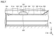
- FIG. 7 is a cross-sectional view showing the bed as viewed in the arrow direction on line VII-VII in FIG. 6;
- FIG. 4 is a top view showing the relationship between the opening area of an opening and the opening area of a processing area;
- FIG. 7 is a top view partially showing a modification of the bed in FIG. 6;
- FIG. 10 is a perspective view showing a machine tool (when the table is in a reference posture) according to Embodiment 2 of the present invention;
- FIG. 10 is a perspective view showing a machine tool (when the table is in an inverted posture) according to Embodiment 2 of the present invention;
- FIG. 1 is a perspective view showing a machine tool according to Embodiment 1 of the present invention.
- 2 is a top view showing the machine tool in FIG. 1.
- FIG. 3 is a side view showing the machine tool in FIG. 1.
- FIG. 4 is a front view showing the machine tool in FIG. 1.
- machine tool 100 in the present embodiment is a machining center that processes a workpiece by bringing a rotating tool into contact with the workpiece.
- the machine tool 100 is a horizontal machining center in which the central axis of rotation of the tool extends horizontally.
- the machine tool 100 is an NC (Numerically Controlled) machine tool in which various operations for machining a workpiece are automated by numerical control by a computer.
- an axis that is parallel to the horizontal direction and parallel to the moving direction of the table is referred to as the "Z-axis (first axis)".
- An axis orthogonal to the Z-axis is called an "X-axis (second axis)”
- an axis parallel to the vertical direction is called a "Y-axis (third axis)”.
- the right direction in FIG. 2 is the “+X axis direction” and the left direction is the “ ⁇ X axis direction”.
- the left direction in FIG. 3 is the “+Z axis direction” and the right direction is the “ ⁇ Z axis direction”.
- the upward direction is the “+Y axis direction” and the downward direction is the “ ⁇ Y axis direction”.
- the machine tool 100 has a bed 11 , a column 21 , a saddle 31 , a cross slide 41 and a tool spindle 91 .
- the bed 11 is a base member for supporting the column 21, the saddle 31, the cross slide 41, the tool spindle 91, a table 51 to be described later, and the like, and is installed on the floor of a factory or the like.
- the bed 11 is made of metal such as cast iron.
- the bed 11 has a rectangular shape with long sides extending in the Z-axis direction and short sides extending in the X-axis direction when viewed from above in the Y-axis direction.
- the total length of the bed 11 in the Y-axis direction is smaller than the total length of the bed 11 in the Z-axis direction and smaller than the total length of the bed 11 in the X-axis direction.
- the bed 11 has a first peripheral wall portion 12 and a second peripheral wall portion 13 .
- the first peripheral wall portion 12 and the second peripheral wall portion 13 are provided on the periphery of the bed 11 when viewed from above.
- the first peripheral wall portion 12 and the second peripheral wall portion 13 are provided at both ends of the bed 11 in the X-axis direction.
- the first peripheral wall portion 12 is provided at the end of the bed 11 in the -X-axis direction.
- the second peripheral wall portion 13 is provided at the end of the bed 11 in the +X-axis direction.
- the first peripheral wall portion 12 and the second peripheral wall portion 13 extend along the Z-axis direction while forming a wall shape that rises upward.
- the first peripheral wall portion 12 has a first top surface 16 .
- the second peripheral wall portion 13 has a second top surface 17 .
- the first top surface 16 and the second top surface 17 are planes parallel to the X-axis-Z-axis plane.
- the first top surface 16 and the second top surface 17 face upward.
- the bed 11 further has a first guide mounting portion 14 and a second guide mounting portion 15 .
- the first guide mounting portion 14 forms a step recessed downward from the first peripheral wall portion 12 .
- the second guide mounting portion 15 forms a step recessed downward from the second peripheral wall portion 13 .
- the first guide mounting portion 14 is provided between the first peripheral wall portion 12 and the second guide mounting portion 15 in the X-axis direction.
- the second guide mounting portion 15 is provided between the first guide mounting portion 14 and the second peripheral wall portion 13 in the X-axis direction.
- the first guide mounting portion 14 has a third top surface 18 .
- the first top surface 16 is arranged above the third top surface 18 .
- the first peripheral wall portion 12 has a wall shape rising upward from the third top surface 18 .
- the second guide mounting portion 15 has a fourth top surface 19 .
- the second top surface 17 is arranged above the fourth top surface 19 .
- the second peripheral wall portion 13 has a wall shape rising upward from the fourth top surface 19 .
- the column 21 is erected on the bed 11.
- the column 21 as a whole has a gate shape rising upward from the bed 11 .
- Column 21 is fixed to bed 11 .
- the column 21 is arranged at the end of the bed 11 in the -Z-axis direction.
- the saddle 31 is supported by the column 21.
- the saddle 31 is provided on the front surface of the column 21 facing the +Z-axis direction.
- the saddle 31 as a whole has a portal shape rising upward from the bed 11 .
- the saddle 31 is provided movably in the X-axis direction with respect to the column 21 by feeding devices 22 and 23 and guide portions 26 and 27 provided on the column 21 and the like.
- the cross slide 41 is supported by the saddle 31.
- the cross slide 41 is provided on the front surface of the saddle 31 facing the +Z-axis direction.
- the cross slide 41 as a whole has a plate shape parallel to the X-axis-Y-axis plane.
- the cross slide 41 is provided movably in the Y-axis direction (vertical direction) with respect to the saddle 31 by feed devices 42 and 43 and guide portions 46 and 47 provided on the saddle 31 and the like.
- the tool spindle 91 is supported by the cross slide 41.
- the tool spindle 91 is fixed with respect to the cross slide 41 .
- the tool spindle 91 passes through the cross slide 41 and protrudes from the cross slide 41 in the +Z-axis direction and the ⁇ Z-axis direction.
- a tool spindle 91 is supported by the column 21 via a cross slide 41 .
- the tool spindle 91 moves in the Y-axis direction (vertical direction) together with the cross slide 41 with respect to the saddle 31 .
- the tool spindle 91 is provided so as to be rotatable by motor drive around a rotation center axis 110 parallel to the Z-axis.
- the tool spindle 91 holds a tool for machining a workpiece in the machine tool 100 .
- the tool spindle 91 rotates, the tool held by the tool spindle 91 rotates about the rotation center axis 110 .
- the machine tool 100 further has a table 51.
- a table 51 is supported by the bed 11 .
- a table 51 is provided on the bed 11 .
- the table 51 is provided at a position separated from the column 21, the saddle 31 and the cross slide 41 in the +Z-axis direction.
- a table 51 is a device for holding a work.
- the table 51 holds the workpiece at a position facing the tool spindle 91 in the Z-axis direction.
- the table 51 is provided movably in the Z-axis direction with respect to the bed 11 .
- the table 51 has a work holding portion 61 and a table base 71 .
- the work holding part 61 is provided on the bed 11 .
- the work holding portion 61 is arranged between the first peripheral wall portion 12 and the second peripheral wall portion 13 in the X-axis direction.
- the work holding portion 61 detachably holds a work.
- a pallet P is attached to the work holding portion 61 .
- On the pallet P for example, jigs such as tombstones to which works are attached are mounted.
- the work holding portion 61 is supported by a table base 71.
- the table base 71 is provided below the workpiece holder 61 .
- the table base 71 straddles between the first guide mounting portion 14 (third top surface 18) and the second guide mounting portion 15 (fourth top surface 19) in the X-axis direction. is provided.
- the workpiece holding unit 61 includes a rotating mechanism (not shown) for rotating the pallet P around a rotation center axis 130 extending in the Y-axis direction, and a clamping mechanism (not shown) for clamping and unclamping the pallet P. (not shown) are built in.
- the machine tool 100 further has an automatic pallet changer (APC: Automatic Pallet Changer) 321 .
- the automatic pallet changer 321 is arranged on the opposite side of the tool spindle 91 across the table 51 in the Z-axis direction.
- An automatic pallet changer 321 is attached to the bed 11 .
- the automatic pallet exchange device 321 exchanges pallets mounted on the table 51 .
- the automatic pallet changer 321 changes pallets inside and outside the processing area.
- the table 51 is arranged at the pallet exchange position corresponding to the stroke end in the +Z-axis direction.
- the automatic pallet exchange device 321 exchanges the pallet P on the table 51 inside the machining area with the pallet at the setup station (not shown) outside the machining area.
- the automatic pallet changer 321 simultaneously holds the pallet P on the table 51 and the pallet on the setup station, and is composed of an arm mechanism capable of vertical movement and pivoting movement about a vertical axis.
- the structure of the automatic pallet changer 321 is not particularly limited, and may be composed of, for example, an arm mechanism capable of vertical movement and sliding movement in the Z-axis direction.
- FIG. 5 is a perspective view showing the bed in FIG. 1.
- FIG. 6 is a top view showing the bed in FIG. 1.
- FIG. 7 is a cross-sectional view showing the bed as viewed in the arrow direction on line VII-VII in FIG.
- the bed 11 further has an APC mounting portion 311 and a column mounting portion 240. As shown in FIG.
- the APC mounting portion 311 is provided at the end of the bed 11 in the +Z-axis direction.
- the APC mounting portion 311 is arranged between the first guide mounting portion 14 and the second guide mounting portion 15 in the X-axis direction.
- the APC mounting portion 311 extends in the X-axis direction and connects the first guide mounting portion 14 and the second guide mounting portion 15 .
- the APC mounting portion 311 is connected to the first guide mounting portion 14 at the end in the -X-axis direction.
- the APC attachment portion 311 is connected to the second guide attachment portion 15 at the end in the +X-axis direction.
- the column attachment part 240 is provided at the end of the bed 11 in the -Z-axis direction.
- the column attachment portion 240 extends in the X-axis direction and connects the first guide attachment portion 14 and the second guide attachment portion 15 .
- the column mounting portion 240 is connected to the ends of the first peripheral wall portion 12 and the first guide mounting portion 14 in the ⁇ Z-axis direction at the ends in the ⁇ X-axis direction.
- the column mounting portion 240 is connected to the ends of the second peripheral wall portion 13 and the second guide mounting portion 15 in the ⁇ Z-axis direction at the ends in the +X-axis direction.
- An automatic pallet changer 321 is attached to the APC attachment part 311 .
- the column 21 is attached to the column attachment portion 240 .
- Column mounting portion 240 has a fifth top surface 241 .
- the column 21 rests on the fifth top surface 241 .
- the first guide mounting portion 14 and the second guide mounting portion 15 further have a first guide mounting surface 221 and a second guide mounting surface 226, respectively.
- the first guide mounting surface 221 and the second guide mounting surface 226 are planes parallel to the X-axis-Z-axis plane.
- the first guide mounting surface 221 and the second guide mounting surface 226 extend in a belt shape in the Z-axis direction.
- the machine tool 100 further has a first feed device 52 , a second feed device 53 , a first guide section 58 and a second guide section 59 .
- the table 51 is provided movably in the Z-axis direction by a first feeder 52 , a second feeder 53 , a first guide portion 58 and a second guide portion 59 .
- the first feeding device 52 and the second feeding device 53 are provided on the bed 11 and the table 51.
- the first feeding device 52 and the second feeding device 53 are arranged apart from each other in the X-axis direction.
- the first feeding device 52 and the second feeding device 53 are provided on the third top surface 18 and the fourth top surface 19, respectively.
- the first feeding device 52 and the second feeding device 53 move the table 51 in the Z-axis direction by applying a driving force to the table 51 .
- the first feeding device 52 has a servomotor 261, a screw shaft 262 and a nut 263.
- the second feeding device 53 has a servomotor 266 , a screw shaft 267 and a nut 268 .
- the screw shaft 262 extends in the Z-axis direction.
- the screw shaft 262 is rotatably supported by a plurality of bearings arranged apart from each other in the Z-axis direction.
- the nut 263 is fitted onto the screw shaft 262 via a plurality of balls.
- the nut 263 is attached to the table 51 (table base 71).
- the screw shaft 262 and nut 263 constitute a ball screw.
- the output shaft of the servomotor 261 is connected to the screw shaft 262 . Rotation from the servomotor 261 is input to the screw shaft 262 .
- the screw shaft 267 extends in the Z-axis direction.
- the screw shaft 267 is rotatably supported by a plurality of bearings arranged apart from each other in the Z-axis direction.
- the nut 268 is fitted onto the screw shaft 267 via a plurality of balls.
- the nut 268 is attached to the table 51 (table base 71).
- the screw shaft 267 and nut 268 constitute a ball screw.
- the output shaft of the servomotor 266 is connected to the screw shaft 267 . Rotation from the servomotor 266 is input to the screw shaft 267 .
- the first guide part 58 and the second guide part 59 are provided on the bed 11 and the table 51 .
- the first guide portion 58 and the second guide portion 59 are arranged apart from each other in the X-axis direction.
- the first guide portion 58 and the second guide portion 59 are attached to the first guide attachment portion 14 and the second guide attachment portion 15, respectively.
- the first guide portion 58 and the second guide portion 59 guide the table 51 in the Z-axis direction.
- the first guide part 58 is arranged side by side with the first feeding device 52 in the X-axis direction.
- the second guide portion 59 is arranged side by side with the second feeding device 53 in the X-axis direction.
- the first guide portion 58 is arranged between the first feeding device 52 and the second guide portion 59 in the X-axis direction.
- the second guide portion 59 is arranged between the first guide portion 58 and the second feeding device 53 in the X-axis direction.
- the first guide portion 58 has rails 271 and sliders 272 .
- the rail 271 extends in the Z-axis direction.
- the rail 271 is attached to the first guide attachment surface 221 using bolts.
- the slider 272 is fitted to the rail 271 via a plurality of balls.
- the slider 272 is slidable in the Z-axis direction by being guided by the rails 271 .
- the slider 272 is attached to the table 51 (table base 71).
- the rail 271 and slider 272 constitute a linear guide, which is a linear guide mechanism.
- the second guide portion 59 has rails 276 and sliders 277 .
- Rail 276 extends in the Z-axis direction.
- the rail 276 is attached to the second guide mounting surface 226 using bolts.
- the slider 277 is fitted to the rail 276 via a plurality of balls.
- the slider 277 is slidable in the Z-axis direction by being guided by rails 276 .
- the slider 277 is attached to the table 51 (table base 71).
- the rail 276 and slider 277 constitute a linear guide, which is a linear guide mechanism.
- the bed 11 is provided with an opening 211.
- the opening 211 is positioned between the first guide mounting portion 14 and the second guide mounting portion 15 in the X-axis direction.
- the opening 211 is positioned between the APC mounting portion 311 and the column mounting portion 240 in the Z-axis direction.
- the opening 211 penetrates the bed 11 in the Y-axis direction.
- FIG. 6 shows the rotation center axis 130S of the pallet P when the table 51 is positioned at the stroke end in the +Z-axis direction, that is, the pallet exchange position by the automatic pallet changer 321, and the table 51 in the -Z-axis direction.
- a rotation center axis 130T of the pallet P when positioned at the stroke end is shown.
- the opening 211 has a first open end 211p and a second open end 211q.
- the first opening end 211p is arranged at one end of the opening 211 in the Z-axis direction.
- the first opening end 211p corresponds to the end of the opening 211 in the +Z-axis direction.
- the second opening end 211q is arranged at the other end of the opening 211 in the Z-axis direction.
- the second opening end 211q corresponds to the end of the opening 211 in the -Z-axis direction.
- the length L1 between the first opening end 211p and the second opening end 211q in the Z-axis direction is longer than the length L2 of the opening 211 in the X-axis direction (L1>L2).
- the opening 211 has a rectangular shape with the longitudinal direction in the Z-axis direction and the lateral direction in the X-axis direction when viewed from above.
- the opening 211 has a rectangular shape when viewed from above, and forms an opening (space) that extends in the Y-axis direction (vertical direction) and penetrates the bed 11 .
- the length L1 between the first opening end 211p and the second opening end 211q in the Z-axis direction is longer than the maximum stroke length L3 of the table 51 in the Z-axis direction (L1>L3).
- the rotation center axis 130S of the pallet P is arranged at a position overlapping a third opposing surface 244, which will be described later, when viewed from above.
- the rotation center axis 130S of the pallet P is arranged at a position closer to the +Z-axis direction than the first opening end 211p.
- the rotation center axis 130T of the pallet P is arranged at a position overlapping the opening of the opening 211 when viewed from above.
- a spindle end face 92 of the tool spindle 91 is arranged at a position overlapping the opening of the opening 211 in top view.
- a chip discharge mechanism (not shown) is provided directly below the opening 211 to discharge chips generated by machining the work in the machine tool 100 to the outside of the machine.
- the first guide mounting portion 14 and the second guide mounting portion 15 have a first facing surface 222 and a second facing surface 227, respectively.
- the first opposing surface 222 and the second opposing surface 227 face each other across the opening 211 in the X-axis direction.
- the first opposing surface 222 is provided side by side with the first guide mounting surface 221 in the X-axis direction.
- the first opposing surface 222 is inclined downward in the X-axis direction from the first guide mounting surface 221 toward the opening 211 .
- the first opposing surface 222 extends from the first guide mounting surface 221 toward the opening 211 in the +X-axis direction and the -Y-axis direction.
- the 1st opposing surface 222 consists of planes.
- the first opposing surface 222 extends along the first guide mounting surface 221 in the Z-axis direction in a strip shape when viewed from above.
- the second facing surface 227 is provided side by side with the second guide mounting surface 226 in the X-axis direction.
- the second opposing surface 227 is inclined downward from the second guide mounting surface 226 toward the opening 211 in the X-axis direction.
- the second facing surface 227 extends from the second guide mounting surface 226 toward the opening 211 in the ⁇ X-axis direction and the ⁇ Y-axis direction.
- the second facing surface 227 consists of a plane.
- the second facing surface 227 extends in the Z-axis direction along the second guide mounting surface 226 in a strip shape when viewed from above.
- the first facing surface 222 and the second facing surface 227 are provided symmetrically with the table 51 interposed therebetween.
- the APC mounting portion 311 and the column mounting portion 240 have a third facing surface 244 and a fourth facing surface 243, respectively.
- the third opposing surface 244 and the fourth opposing surface 243 face each other with the opening 211 interposed therebetween in the Z-axis direction.
- the third facing surface 244 is inclined downward as it approaches the opening 211 in the Z-axis direction.
- the third facing surface 244 extends in the ⁇ Z-axis direction and the ⁇ Y-axis direction toward the opening 211 .
- the third facing surface 244 consists of a plane.
- the third facing surface 244 extends in the X-axis direction in a strip shape.
- the third opposing surface 244 is connected at its ⁇ X-axis direction end to the +Z-axis direction end of the first opposing surface 222 .
- the end of the third opposing surface 244 in the +X-axis direction is connected to the end of the second opposing surface 227 in the +Z-axis direction.
- the fourth opposing surface 243 is inclined downward as it approaches the opening 211 in the Z-axis direction.
- the fourth opposing surface 243 extends in the +Z-axis direction and the ⁇ Y-axis direction toward the opening 211 .
- the fourth opposing surface 243 consists of a plane.
- the fourth facing surface 243 extends in the X-axis direction in a strip shape.
- the fourth facing surface 243 is connected to the end of the first facing surface 222 in the ⁇ Z-axis direction at the end in the ⁇ X-axis direction.
- the fourth facing surface 243 is connected to the end of the second facing surface 227 in the ⁇ Z-axis direction at its +X-axis direction end.
- the first opposing surface 222 , the third opposing surface 244 , the second opposing surface 227 and the fourth opposing surface 243 are provided so as to surround the opening 211 .
- the column mounting portion 240 further has an inclined surface 242 .
- the inclined surface 242 is arranged between the fifth top surface 241 and the third top surface 18, the fourth opposing surface 243 and the fourth top surface 19 in the Z-axis direction.
- the inclined surface 242 is inclined downward in the Z-axis direction from the fifth top surface 241 toward the third top surface 18 , the fourth opposing surface 243 and the fourth top surface 19 .
- the inclined surface 242 extends from the fifth top surface 241 toward the third top surface 18, the fourth opposing surface 243 and the fourth top surface 19 in the +Z-axis direction and the -Y-axis direction.
- the inclination of the inclined surface 242 may be steeper than the inclination of the fourth opposing surface 243, may be the same as the inclination of the fourth opposing surface 243, or may be gentler than the inclination of the fourth opposing surface 243.
- the inclination of the fourth opposing surface 243 may be steeper than the inclination of the third opposing surface 244 , may be the same as the inclination of the third opposing surface 244 , or may be steeper than the inclination of the third opposing surface 244 . may also be gradual.
- the bed 11 further has ribs 231 .
- the rib portion 231 is arranged in the opening portion 211 .
- the rib portion 231 extends like a rib in the X-axis direction.
- the rib portion 231 is connected to the first facing surface 222 and the second facing surface 227 .
- the rib portion 231 is provided integrally with the first guide mounting portion 14 and the second guide mounting portion 15 by cast iron forming the bed 11 .
- the rib portion 231 is provided so as to overlap the opening of the opening portion 211 when viewed from above.
- the rib portion 231 is arranged between the first open end 211p and the second open end 211q in the Z-axis direction.
- the rib portion 231 is arranged at a position closer to the first opening end 211p than the second opening end 211q in the Z-axis direction.
- the rib portion 231 is arranged between the rotation center axis 130S of the pallet P and the rotation center axis 130T of the pallet P in the Z-axis direction.
- the rib portion 231 is arranged at a position closer to the rotation center axis 130T of the pallet P than the rotation center axis 130S of the pallet P in the Z-axis direction.
- the rib portion 231 may be arranged at a central position between the first open end 211p and the second open end 211q in the Z-axis direction, or at a position closer to the second open end 211q than the first open end 211p. may be placed.
- the rib portion 231 may be arranged at a center position between the rotation center axis 130S of the pallet P and the rotation center axis 130T of the pallet P in the Z-axis direction, or may It may be arranged at a position closer to the rotation center axis 130S of the pallet P.
- the rib portion 231 is arranged at a position closer to the +Z-axis direction than the spindle end surface 92 of the tool spindle 91 in the Z-axis direction.
- the length L1 between the first opening end 211p and the second opening end 211q in the Z-axis direction is longer than the length L2 of the opening 211 in the X-axis direction.
- a length L1 between the first opening end 211p and the second opening end 211q in the Z-axis direction is longer than the maximum stroke length L3 of the table 51 in the Z-axis direction.
- FIG. 7 shows the cross-sectional shape of the rib portion 231 cut along the Y-axis-Z-axis plane.
- the rib portion 231 has a lower surface 232 , a first side surface 233 , a second side surface 234 , a first inclined surface 235 and a second inclined surface 236 .
- the lower surface 232 extends parallel to the horizontal plane (X-axis-Y-axis plane).
- the first side surface 233 and the second side surface 234 rise from both ends of the lower surface 232 in the Z-axis direction.
- the first side surface 233 rises from the end of the lower surface 232 in the +Z-axis direction
- the second side surface 234 rises from the end of the lower surface 232 in the -Z-axis direction.
- the first side surface 233 and the second side surface 234 extend parallel to the vertical plane (X axis-Y axis).
- the first inclined surface 235 extends obliquely upward along the Z-axis direction from the upper end of the first side surface 233 .
- the first inclined surface 235 extends from the upper end of the first side surface 233 in the ⁇ Z-axis direction and the +Y-axis direction.
- the first slanted surface 235 is slanted such that the inclination becomes gentler as the distance from the upper end of the first side surface 233 increases.
- the first inclined surface 235 is a curved surface that is convex upward.
- the first inclined surface 235 may be configured as a flat surface.
- the second inclined surface 236 extends obliquely upward along the Z-axis direction from the upper end of the second side surface 234 .
- the second inclined surface 236 extends from the upper end of the second side surface 234 in the +Z-axis direction and the +Y-axis direction.
- the second slanted surface 236 is slanted so that the inclination becomes gentler as it moves away from the upper end of the second side surface 234 .
- the second inclined surface 236 is a curved surface that is convex upward.
- the second inclined surface 236 intersects with the first inclined surface 235 .
- the second inclined surface 236 may be composed of a flat surface.
- the first inclined surface 235 and the second inclined surface 236 can prevent chips from accumulating on the upper portion of the rib portion 231 .
- the rectangular shape formed by the lower surface 232 , the first side surface 233 and the second side surface 234 can sufficiently ensure the geometrical moment of inertia of the rib portion 231 . Thereby, the rigidity of the bed 11 can be further enhanced by the rib portion 231 .
- FIG. 8 is a top view showing the relationship between the opening area of the opening and the opening area of the processing area.
- machine tool 100 further has cover body 281 .
- the cover body 281 defines a processing area 300 .
- the machining area 300 is a space in which the work is machined on the bed 11, and is sealed so that foreign matter such as chips or cutting oil resulting from the machining of the work does not leak out of the machining area 300.
- the opening area S1 of the opening 211 when cut by a horizontal plane is 20% or more of the area S2 of the processing area 300 when cut by a horizontal plane (S1 ⁇ 0.2 ⁇ S2).
- the area of the processing area 300 cut by a horizontal plane may change depending on the position (height) of the horizontal plane.
- the area S2 of the processing area 300 cut by the horizontal plane is the maximum value among the varying areas.
- the opening area S1 of the opening 211 may be 25% or more of the area S2 of the processing area 300 (S1 ⁇ 0.25 ⁇ S2), or 30% or more of the area S2 of the processing area 300. (S1 ⁇ 0.3 ⁇ S2).
- the bed 11 has a first fixing portion 251, a second fixing portion 255, and a third fixing portion 253 (in drawings other than FIG. 6, the first fixing portion 251, the The illustration of the second fixing portion 255 and the third fixing portion 253 is omitted).
- the first fixing part 251 , the second fixing part 255 and the third fixing part 253 are provided integrally with the bed 11 .
- the first fixing part 251, the second fixing part 255 and the third fixing part 253 are fixed to the floor FL on which the machine tool 100 is installed.
- first fixing portion 251, the second fixing portion 255 and the third fixing portion 253 are fastened to the foundation of the floor FL on which the machine tool 100 is installed using anchor bolts (not shown). ing.
- the first fixing portion 251, the second fixing portion 255, and the third fixing portion 253 are provided with a bolt insertion hole 252, a bolt insertion hole 256, and a bolt insertion hole 254, into which anchor bolts are inserted, respectively.
- the first fixing part 251, the second fixing part 255, and the third fixing part 253 are provided at the bottom of the bed 11 and at the peripheral edge of the bed 11 when viewed from above.
- the first fixing part 251 is provided below the APC mounting part 311 .
- the first fixing portion 251 is provided at a position overlapping a center line 131 that passes through the rotation center axis 130 of the table 51 and extends in the Z-axis direction when viewed from above.
- the second fixing part 255 and the third fixing part 253 are provided on the column mounting part 240 .
- the second fixing portion 255 and the third fixing portion 253 are positioned apart from each other in the X-axis direction.
- the second fixing portion 255 and the third fixing portion 253 are provided at both ends of the column mounting portion 240 in the X-axis direction.
- the APC attachment portion 311 provided at the end of the opening 211 in the +Z-axis direction is fixed to the floor FL by the first fixing portion 251, and the end of the opening 211 in the ⁇ Z-axis direction is fixed to the floor FL.
- a column mounting portion 240 provided in the column is fixed to the floor surface by a second fixing portion 255 and a third fixing portion 253 .
- the number of fixing points in the APC mounting portion 311 is smaller than that in the column mounting portion 240, when an external force is applied to the bed 11, vibration occurs on the end side of the opening 211 in the +Z-axis direction. becomes easier.
- the rib portion 231 is provided at a position closer to the first opening end 211p than the second opening end 211q in the Z-axis direction. Accordingly, since the first opening end 211p corresponds to the end of the opening 211 in the +Z-axis direction where the APC mounting portion 311 is provided, the vibration of the bed 11 can be suppressed more effectively. In addition, since the rib portion 231 is provided at a position farther apart from the column 21 in the Z-axis direction, chips generated by machining the workpiece by the tool spindle 91 can be efficiently discharged through the opening portion 211 .
- FIG. 9 is a top view partially showing a modification of the bed in FIG. Referring to FIG. 9, in this modification, when the table 51 is positioned at the stroke end in the +Z-axis direction, that is, at the pallet exchange position by the automatic pallet exchange device 321, the rotation center axis 130S of the table 51 It is arranged at a position overlapping with the opening of the opening 211 when viewed.
- the machine tool 100 according to the present embodiment is movable in the Z-axis direction as the first axial direction parallel to the horizontal direction.
- the first guide mounting portion 14 and the second guide mounting portion 15 respectively include a first opposing surface 222 and a second opposing surface 227 that face each other across the opening 211 in the X-axis direction.
- the bed 11 further has a rib portion 231 arranged in the opening 211 and connected to the first opposing surface 222 and the second opposing surface 227 .
- chips can be efficiently collected from the machining area 300 on the bed 11 while sufficiently ensuring the rigidity of the bed 11. can.
- FIG. 10 is a perspective view showing a machine tool (when the table is in a reference posture) according to Embodiment 2 of the present invention.
- FIG. 11 is a perspective view showing a machine tool (when the table is in an inverted posture) according to Embodiment 2 of the present invention.
- a machine tool according to the present embodiment has basically the same structure as machine tool 100 according to the first embodiment. Hereinafter, descriptions of overlapping structures will not be repeated.
- the table 51 is provided so as to be rotatable around a turning center axis 120 parallel to the X-axis direction.
- the machine tool 100 has a third guide portion 56 and a fourth guide portion 57 in addition to the first guide portion 58 and the second guide portion 59 .
- the third guide portion 56 and the fourth guide portion 57 are attached to the first peripheral wall portion 12 and the second peripheral wall portion 13, respectively.
- the third guide portion 56 and the fourth guide portion 57 are provided on the first top surface 16 and the second top surface 17, respectively.
- the third guide portion 56 and the fourth guide portion 57 guide the table 51 in the Z-axis direction together with the first guide portion 58 and the second guide portion 59 .
- the first feeding device 52 and the second feeding device 53 are provided on the first top surface 16 and the second top surface 17, respectively.
- the table 51 has a workpiece holding portion 61, a table base 71 (71J, 71K), and a turning device 81.
- the work holding part 61 is provided on the bed 11.
- the work holding portion 61 is provided across the first peripheral wall portion 12 and the second peripheral wall portion 13 in the X-axis direction.
- the work holding portion 61 is supported by a table base 71 .
- the table base 71 has a first support portion 72 and a second support portion 73 .
- the first support portion 72 and the second support portion 73 face each other with the work holding portion 61 interposed therebetween in the X-axis direction.
- the work holding portion 61 is supported by the first support portion 72 and the second support portion 73 so as to be rotatable about the turning center axis 120 .
- the table base 71 has a first table base 71J and a second table base 71K.
- the first table base 71J and the second table base 71K are provided apart from each other in the X-axis direction.
- the first table base 71J and the second table base 71K are separated in the X-axis direction.
- the first table base 71J and the second table base 71K are separated in a range overlapping the opening 211 of the bed 11 when viewed from above.
- the first feeding device 52, the third guide portion 56 and the first guide portion 58 are connected to the first table base 71J.
- a second feeding device 53, a fourth guide portion 57 and a second guide portion 59 are connected to the second table base 71K.
- the first table base 71J has a first support portion 72.
- the second table base 71K has a second support portion 73 .
- the first support portion 72 is provided above the first peripheral wall portion 12 .
- the second support portion 73 is provided above the second peripheral wall portion 13 .
- the turning device 81 is provided on the first support portion 72 .
- the turning device 81 is built in the first support portion 72 .
- the turning device 81 turns the work holding portion 61 around the turning center axis 120 .
- the structure in which the table base 71 is divided into the first table base 71J and the second table base 71K makes it possible to further improve the dischargeability of chips generated on the pallet P during work processing. .
- the bed 11 in Embodiment 1 and the bed 11 in this embodiment have the same structure.
- Embodiment 2 of the present invention configured in this way, the effects described in Embodiment 1 can be achieved in the same manner.
- This invention is applied to machine tools such as horizontal machining centers.
Abstract
Description
図1は、この発明の実施の形態1における工作機械を示す斜視図である。図2は、図1中の工作機械を示す上面図である。図3は、図1中の工作機械を示す側面図である。図4は、図1中の工作機械を示す正面図である。
図10は、この発明の実施の形態2における工作機械(テーブルの基準姿勢時)を示す斜視図である。図11は、この発明の実施の形態2における工作機械(テーブルの反転姿勢時)を示す斜視図である。本実施の形態における工作機械は、実施の形態1における工作機械100と比較して、基本的には同様の構造を備える。以下、重複する構造については、その説明を繰り返さない。
Claims (7)
- 水平方向に平行な第1軸方向に移動可能なテーブルと、
前記テーブルを前記第1軸方向に案内し、水平方向に平行で、かつ、前記第1軸に直交する第2軸方向に互いに離れて配置される第1ガイド部および第2ガイド部と、
前記第1ガイド部および前記第2ガイド部がそれぞれ取り付けられる第1ガイド取り付け部および第2ガイド取り付け部を有し、前記第1ガイド取り付け部および前記第2ガイド取り付け部の間に位置し、鉛直方向に平行な第3軸方向に貫通する開口部が設けられるベッドとを備え、
前記第1ガイド取り付け部および前記第2ガイド取り付け部は、それぞれ、前記第2軸方向において、前記開口部を挟んで互いに対向する第1対向面および第2対向面を含み、
前記ベッドは、前記開口部に配置され、前記第1対向面および前記第2対向面に接続されるリブ部をさらに有する、工作機械。 - 前記開口部は、前記第1軸方向における前記開口部の一方端に配置される第1開口端と、前記第1軸方向における前記開口部の他方端に配置される第2開口端とを有し、
前記第1軸方向における前記第1開口端および前記第2開口端の間の長さは、前記第2軸方向における前記開口部の長さよりも大きい、請求項1に記載の工作機械。 - 前記開口部は、前記第1軸方向における前記開口部の一方端に配置される第1開口端と、前記第1軸方向における前記開口部の他方端に配置される第2開口端とを有し、
前記第1軸方向における前記第1開口端および前記第2開口端の間の長さは、前記第1軸方向における前記テーブルの最大ストローク長よりも大きい、請求項1または2に記載の工作機械。 - 前記テーブルに装着されるパレットを交換するための自動パレット交換装置(APC:Automatic Pallet Changer)をさらに備え、
前記ベッドは、前記第1軸方向における前記開口部の一方端側において、前記第1ガイド取り付け部および前記第2ガイド取り付け部を繋ぎ、前記自動パレット交換装置が取り付けられるAPC取り付け部をさらに有し、
前記テーブルは、前記第3軸方向に延びる回転中心軸を中心に回転可能であり、
前記テーブルが前記自動パレット交換装置によるパレット交換位置に位置決めされた場合に、前記回転中心軸は、前記第3軸方向に見て前記開口部の開口に重なる位置に配置される、請求項1から3のいずれか1項に記載の工作機械。 - 前記ベッド上に加工エリアを区画形成するカバー体をさらに備え、
水平面により切断された場合の前記開口部の開口面積は、水平面により切断された場合の前記加工エリアの面積の20%以上である、請求項1から4のいずれか1項に記載の工作機械。 - 前記リブ部は、水平面に平行な下面と、前記第1軸方向における前記下面の両端部からそれぞれ立ち上がる第1側面および第2側面と、前記第1側面の上端部から前記第1軸方向に沿って斜め上方向に延在する第1傾斜面と、前記第2側面の上端部から前記第1軸方向に沿って斜め上方向に延在し、前記第1傾斜面と交わる第2傾斜面とを含む、請求項1から5のいずれか1項に記載の工作機械。
- 前記テーブルに装着されるパレットを交換するための自動パレット交換装置(APC:Automatic Pallet Changer)と、
工具主軸を支持するためのコラムとをさらに備え、
前記ベッドは、
前記第1軸方向における前記開口部の一方端側において、前記第1ガイド取り付け部および前記第2ガイド取り付け部を繋ぎ、前記自動パレット交換装置が取り付けられるAPC取り付け部と、
前記第1軸方向における前記開口部の他方端側において、前記第1ガイド取り付け部および前記第2ガイド取り付け部を繋ぎ、前記コラムが取り付けられるコラム取り付け部と、
前記APC取り付け部に設けられ、前記工作機械が設置される床面に固定される第1固定部と、
前記コラム取り付け部に設けられ、前記第2軸方向に互いに離れて位置し、前記工作機械が設置される床面に固定される第2固定部および第3固定部とをさらに有し、
前記開口部は、前記第1軸方向における前記開口部の一方端に配置される第1開口端と、前記第1軸方向における前記開口部の他方端に配置される第2開口端とを有し、
前記リブ部は、前記第1軸方向において、前記第2開口端よりも前記第1開口端寄りの位置に設けられる、請求項1に記載の工作機械。
Priority Applications (4)
| Application Number | Priority Date | Filing Date | Title |
|---|---|---|---|
| CN202180097068.4A CN117222495A (zh) | 2021-04-15 | 2021-04-15 | 机床 |
| EP21936967.5A EP4324589A1 (en) | 2021-04-15 | 2021-04-15 | Machine tool |
| PCT/JP2021/015557 WO2022219771A1 (ja) | 2021-04-15 | 2021-04-15 | 工作機械 |
| JP2023514269A JPWO2022219771A1 (ja) | 2021-04-15 | 2021-04-15 |
Applications Claiming Priority (1)
| Application Number | Priority Date | Filing Date | Title |
|---|---|---|---|
| PCT/JP2021/015557 WO2022219771A1 (ja) | 2021-04-15 | 2021-04-15 | 工作機械 |
Publications (1)
| Publication Number | Publication Date |
|---|---|
| WO2022219771A1 true WO2022219771A1 (ja) | 2022-10-20 |
Family
ID=83640224
Family Applications (1)
| Application Number | Title | Priority Date | Filing Date |
|---|---|---|---|
| PCT/JP2021/015557 WO2022219771A1 (ja) | 2021-04-15 | 2021-04-15 | 工作機械 |
Country Status (4)
| Country | Link |
|---|---|
| EP (1) | EP4324589A1 (ja) |
| JP (1) | JPWO2022219771A1 (ja) |
| CN (1) | CN117222495A (ja) |
| WO (1) | WO2022219771A1 (ja) |
Citations (12)
| Publication number | Priority date | Publication date | Assignee | Title |
|---|---|---|---|---|
| JPS55160745U (ja) | 1979-05-08 | 1980-11-18 | ||
| JPS60175540U (ja) * | 1984-04-28 | 1985-11-20 | 豊田工機株式会社 | 治具ベツド分離形nc専用機 |
| JPS60175541U (ja) * | 1984-04-29 | 1985-11-20 | 日立精機株式会社 | 工作機械のベツド構造 |
| JPH0235634U (ja) * | 1988-08-31 | 1990-03-07 | ||
| JP2001058288A (ja) * | 1999-08-20 | 2001-03-06 | Amada Co Ltd | 熱切断加工機のテーブル装置 |
| JP2002326137A (ja) * | 2001-05-02 | 2002-11-12 | Makino Milling Mach Co Ltd | 工作機械 |
| JP2005131768A (ja) * | 2003-10-31 | 2005-05-26 | Toyoda Mach Works Ltd | 工作機械 |
| JP2007054903A (ja) | 2005-08-23 | 2007-03-08 | Jtekt Corp | 工作機械のベッドの構造 |
| JP2007319951A (ja) * | 2006-05-30 | 2007-12-13 | Okuma Corp | パレット交換装置 |
| EP2093013A2 (en) * | 2008-02-01 | 2009-08-26 | SCM GROUP S.p.A. | Structure for machine tool |
| US20100252542A1 (en) * | 2009-04-07 | 2010-10-07 | Trumpf, Inc. | Workpiece processing system |
| JP2017064867A (ja) * | 2015-10-01 | 2017-04-06 | エンシュウ株式会社 | 工作機械 |
-
2021
- 2021-04-15 CN CN202180097068.4A patent/CN117222495A/zh active Pending
- 2021-04-15 EP EP21936967.5A patent/EP4324589A1/en active Pending
- 2021-04-15 JP JP2023514269A patent/JPWO2022219771A1/ja active Pending
- 2021-04-15 WO PCT/JP2021/015557 patent/WO2022219771A1/ja active Application Filing
Patent Citations (12)
| Publication number | Priority date | Publication date | Assignee | Title |
|---|---|---|---|---|
| JPS55160745U (ja) | 1979-05-08 | 1980-11-18 | ||
| JPS60175540U (ja) * | 1984-04-28 | 1985-11-20 | 豊田工機株式会社 | 治具ベツド分離形nc専用機 |
| JPS60175541U (ja) * | 1984-04-29 | 1985-11-20 | 日立精機株式会社 | 工作機械のベツド構造 |
| JPH0235634U (ja) * | 1988-08-31 | 1990-03-07 | ||
| JP2001058288A (ja) * | 1999-08-20 | 2001-03-06 | Amada Co Ltd | 熱切断加工機のテーブル装置 |
| JP2002326137A (ja) * | 2001-05-02 | 2002-11-12 | Makino Milling Mach Co Ltd | 工作機械 |
| JP2005131768A (ja) * | 2003-10-31 | 2005-05-26 | Toyoda Mach Works Ltd | 工作機械 |
| JP2007054903A (ja) | 2005-08-23 | 2007-03-08 | Jtekt Corp | 工作機械のベッドの構造 |
| JP2007319951A (ja) * | 2006-05-30 | 2007-12-13 | Okuma Corp | パレット交換装置 |
| EP2093013A2 (en) * | 2008-02-01 | 2009-08-26 | SCM GROUP S.p.A. | Structure for machine tool |
| US20100252542A1 (en) * | 2009-04-07 | 2010-10-07 | Trumpf, Inc. | Workpiece processing system |
| JP2017064867A (ja) * | 2015-10-01 | 2017-04-06 | エンシュウ株式会社 | 工作機械 |
Also Published As
| Publication number | Publication date |
|---|---|
| JPWO2022219771A1 (ja) | 2022-10-20 |
| EP4324589A1 (en) | 2024-02-21 |
| CN117222495A (zh) | 2023-12-12 |
Similar Documents
| Publication | Publication Date | Title |
|---|---|---|
| US6632054B2 (en) | Portal milling machine | |
| JP4542001B2 (ja) | 工作機械 | |
| JP5025036B2 (ja) | 工作機械のラム案内装置 | |
| JP5811599B2 (ja) | 工作機械 | |
| KR101324666B1 (ko) | 공작기계 | |
| US7063653B2 (en) | Horizontal machining center | |
| WO2022219771A1 (ja) | 工作機械 | |
| KR102165419B1 (ko) | 공작기계의 x축 이송장치 | |
| JP5108361B2 (ja) | 工作機械 | |
| JP5435169B1 (ja) | 工作機械 | |
| CN112475936A (zh) | 一种门型封闭式高刚性结构的五轴小龙门数控加工中心 | |
| CN111975135A (zh) | 一种数控齿轮加工机床 | |
| JP4268842B2 (ja) | 工作機械 | |
| WO2022219772A1 (ja) | 工作機械 | |
| WO2022219773A1 (ja) | 工作機械 | |
| JP7116172B2 (ja) | 工作機械 | |
| CN216990812U (zh) | 一种机床 | |
| JP2008105158A (ja) | 立形工作機械 | |
| JP2002028832A (ja) | 立形主軸を有する装置及びその製造方法 | |
| CN220128123U (zh) | 卧式钻攻一体机 | |
| KR100729473B1 (ko) | 3축집적구조를 갖는 머시닝센터 | |
| CN211916291U (zh) | 数控机床 | |
| JP3843098B2 (ja) | 送り系構造及びこれを備えた工作機械 | |
| CN214641749U (zh) | 一种机床横梁和加工组件的连接结构和门式加工中心 | |
| CN217393831U (zh) | 柔性化铣削设备 |
Legal Events
| Date | Code | Title | Description |
|---|---|---|---|
| 121 | Ep: the epo has been informed by wipo that ep was designated in this application |
Ref document number: 21936967 Country of ref document: EP Kind code of ref document: A1 |
|
| WWE | Wipo information: entry into national phase |
Ref document number: 18286347 Country of ref document: US |
|
| WWE | Wipo information: entry into national phase |
Ref document number: 2023514269 Country of ref document: JP |
|
| WWE | Wipo information: entry into national phase |
Ref document number: 2021936967 Country of ref document: EP |
|
| NENP | Non-entry into the national phase |
Ref country code: DE |
|
| ENP | Entry into the national phase |
Ref document number: 2021936967 Country of ref document: EP Effective date: 20231113 |