WO2022219760A1 - 数値制御装置及びコンピュータが読み取り可能な記憶媒体 - Google Patents
数値制御装置及びコンピュータが読み取り可能な記憶媒体 Download PDFInfo
- Publication number
- WO2022219760A1 WO2022219760A1 PCT/JP2021/015521 JP2021015521W WO2022219760A1 WO 2022219760 A1 WO2022219760 A1 WO 2022219760A1 JP 2021015521 W JP2021015521 W JP 2021015521W WO 2022219760 A1 WO2022219760 A1 WO 2022219760A1
- Authority
- WO
- WIPO (PCT)
- Prior art keywords
- machining
- conditions
- path
- route
- processing
- Prior art date
- Legal status (The legal status is an assumption and is not a legal conclusion. Google has not performed a legal analysis and makes no representation as to the accuracy of the status listed.)
- Ceased
Links
Images








Classifications
-
- G—PHYSICS
- G05—CONTROLLING; REGULATING
- G05B—CONTROL OR REGULATING SYSTEMS IN GENERAL; FUNCTIONAL ELEMENTS OF SUCH SYSTEMS; MONITORING OR TESTING ARRANGEMENTS FOR SUCH SYSTEMS OR ELEMENTS
- G05B19/00—Program-control systems
- G05B19/02—Program-control systems electric
- G05B19/18—Numerical control [NC], i.e. automatically operating machines, in particular machine tools, e.g. in a manufacturing environment, so as to execute positioning, movement or co-ordinated operations by means of program data in numerical form
- G05B19/402—Numerical control [NC], i.e. automatically operating machines, in particular machine tools, e.g. in a manufacturing environment, so as to execute positioning, movement or co-ordinated operations by means of program data in numerical form characterised by control arrangements for positioning, e.g. centring a tool relative to a hole in the workpiece, additional detection means to correct position
-
- B—PERFORMING OPERATIONS; TRANSPORTING
- B23—MACHINE TOOLS; METAL-WORKING NOT OTHERWISE PROVIDED FOR
- B23H—WORKING OF METAL BY THE ACTION OF A HIGH CONCENTRATION OF ELECTRIC CURRENT ON A WORKPIECE USING AN ELECTRODE WHICH TAKES THE PLACE OF A TOOL; SUCH WORKING COMBINED WITH OTHER FORMS OF WORKING OF METAL
- B23H7/00—Processes or apparatus applicable to both electrical discharge machining and electrochemical machining
- B23H7/14—Electric circuits specially adapted therefor, e.g. power supply
- B23H7/20—Electric circuits specially adapted therefor, e.g. power supply for program control, e.g. adaptive
-
- B—PERFORMING OPERATIONS; TRANSPORTING
- B23—MACHINE TOOLS; METAL-WORKING NOT OTHERWISE PROVIDED FOR
- B23H—WORKING OF METAL BY THE ACTION OF A HIGH CONCENTRATION OF ELECTRIC CURRENT ON A WORKPIECE USING AN ELECTRODE WHICH TAKES THE PLACE OF A TOOL; SUCH WORKING COMBINED WITH OTHER FORMS OF WORKING OF METAL
- B23H7/00—Processes or apparatus applicable to both electrical discharge machining and electrochemical machining
- B23H7/02—Wire-cutting
- B23H7/06—Control of the travel curve of the relative movement between electrode and workpiece
-
- G—PHYSICS
- G05—CONTROLLING; REGULATING
- G05B—CONTROL OR REGULATING SYSTEMS IN GENERAL; FUNCTIONAL ELEMENTS OF SUCH SYSTEMS; MONITORING OR TESTING ARRANGEMENTS FOR SUCH SYSTEMS OR ELEMENTS
- G05B19/00—Program-control systems
- G05B19/02—Program-control systems electric
- G05B19/18—Numerical control [NC], i.e. automatically operating machines, in particular machine tools, e.g. in a manufacturing environment, so as to execute positioning, movement or co-ordinated operations by means of program data in numerical form
- G05B19/19—Numerical control [NC], i.e. automatically operating machines, in particular machine tools, e.g. in a manufacturing environment, so as to execute positioning, movement or co-ordinated operations by means of program data in numerical form characterised by positioning or contouring control systems, e.g. to control position from one programmed point to another or to control movement along a programmed continuous path
-
- G—PHYSICS
- G05—CONTROLLING; REGULATING
- G05B—CONTROL OR REGULATING SYSTEMS IN GENERAL; FUNCTIONAL ELEMENTS OF SUCH SYSTEMS; MONITORING OR TESTING ARRANGEMENTS FOR SUCH SYSTEMS OR ELEMENTS
- G05B19/00—Program-control systems
- G05B19/02—Program-control systems electric
- G05B19/18—Numerical control [NC], i.e. automatically operating machines, in particular machine tools, e.g. in a manufacturing environment, so as to execute positioning, movement or co-ordinated operations by means of program data in numerical form
- G05B19/4093—Numerical control [NC], i.e. automatically operating machines, in particular machine tools, e.g. in a manufacturing environment, so as to execute positioning, movement or co-ordinated operations by means of program data in numerical form characterised by part programming, e.g. entry of geometrical information as taken from a technical drawing, combining this with machining and material information to obtain control information, named part program, for the NC machine
- G05B19/40937—Numerical control [NC], i.e. automatically operating machines, in particular machine tools, e.g. in a manufacturing environment, so as to execute positioning, movement or co-ordinated operations by means of program data in numerical form characterised by part programming, e.g. entry of geometrical information as taken from a technical drawing, combining this with machining and material information to obtain control information, named part program, for the NC machine concerning programming of machining or material parameters, pocket machining
-
- B—PERFORMING OPERATIONS; TRANSPORTING
- B23—MACHINE TOOLS; METAL-WORKING NOT OTHERWISE PROVIDED FOR
- B23H—WORKING OF METAL BY THE ACTION OF A HIGH CONCENTRATION OF ELECTRIC CURRENT ON A WORKPIECE USING AN ELECTRODE WHICH TAKES THE PLACE OF A TOOL; SUCH WORKING COMBINED WITH OTHER FORMS OF WORKING OF METAL
- B23H1/00—Electrical discharge machining, i.e. removing metal with a series of rapidly recurring electrical discharges between an electrode and a workpiece in the presence of a fluid dielectric
-
- G—PHYSICS
- G05—CONTROLLING; REGULATING
- G05B—CONTROL OR REGULATING SYSTEMS IN GENERAL; FUNCTIONAL ELEMENTS OF SUCH SYSTEMS; MONITORING OR TESTING ARRANGEMENTS FOR SUCH SYSTEMS OR ELEMENTS
- G05B2219/00—Program-control systems
- G05B2219/30—Nc systems
- G05B2219/45—Nc applications
- G05B2219/45043—EDM machine, wire cutting
-
- G—PHYSICS
- G05—CONTROLLING; REGULATING
- G05B—CONTROL OR REGULATING SYSTEMS IN GENERAL; FUNCTIONAL ELEMENTS OF SUCH SYSTEMS; MONITORING OR TESTING ARRANGEMENTS FOR SUCH SYSTEMS OR ELEMENTS
- G05B2219/00—Program-control systems
- G05B2219/30—Nc systems
- G05B2219/45—Nc applications
- G05B2219/45221—Edm, electrical discharge machining, electroerosion, ecm, chemical
-
- G—PHYSICS
- G05—CONTROLLING; REGULATING
- G05B—CONTROL OR REGULATING SYSTEMS IN GENERAL; FUNCTIONAL ELEMENTS OF SUCH SYSTEMS; MONITORING OR TESTING ARRANGEMENTS FOR SUCH SYSTEMS OR ELEMENTS
- G05B2219/00—Program-control systems
- G05B2219/30—Nc systems
- G05B2219/49—Nc machine tool, till multiple
- G05B2219/49164—Corner, making corner
-
- G—PHYSICS
- G05—CONTROLLING; REGULATING
- G05B—CONTROL OR REGULATING SYSTEMS IN GENERAL; FUNCTIONAL ELEMENTS OF SUCH SYSTEMS; MONITORING OR TESTING ARRANGEMENTS FOR SUCH SYSTEMS OR ELEMENTS
- G05B2219/00—Program-control systems
- G05B2219/30—Nc systems
- G05B2219/50—Machine tool, machine tool null till machine tool work handling
- G05B2219/50357—Tool tangential to path or surface
-
- Y—GENERAL TAGGING OF NEW TECHNOLOGICAL DEVELOPMENTS; GENERAL TAGGING OF CROSS-SECTIONAL TECHNOLOGIES SPANNING OVER SEVERAL SECTIONS OF THE IPC; TECHNICAL SUBJECTS COVERED BY FORMER USPC CROSS-REFERENCE ART COLLECTIONS [XRACs] AND DIGESTS
- Y02—TECHNOLOGIES OR APPLICATIONS FOR MITIGATION OR ADAPTATION AGAINST CLIMATE CHANGE
- Y02P—CLIMATE CHANGE MITIGATION TECHNOLOGIES IN THE PRODUCTION OR PROCESSING OF GOODS
- Y02P90/00—Enabling technologies with a potential contribution to greenhouse gas [GHG] emissions mitigation
- Y02P90/02—Total factory control, e.g. smart factories, flexible manufacturing systems [FMS] or integrated manufacturing systems [IMS]
Definitions
- the present invention relates to a numerical controller for controlling an electric discharge machine and a computer-readable storage medium.
- an electric discharge machine that performs machining by using an electric discharge phenomenon between a workpiece and a traveling electrode.
- electrical discharge machining after cutting out the material once, machining is repeated two or three times so as to trace the side surface of the workpiece, thereby improving the shape accuracy and reducing the roughness of the machined surface.
- the electrical discharge machining energy which is determined by the voltage value (current value) and pulse width, is gradually reduced in the order of rough machining, semi-finishing, and final finishing. Since the machined surface is not flat at the stage of rough machining, the machined surface is gradually flattened while decreasing the voltage value (current value) and pulse width.
- the distance between the electrodes where the discharge occurs is called the discharge gap, and can be predicted from the machining conditions such as the current value and pulse width.
- a correction path is created and excessive cutting is determined using a diameter correction amount based on a predicted value as a machining radius.
- Patent Literature 1 discloses that "a wire electric discharge machining apparatus comprises a machining unit that forms a product portion that is an inner part by cutting off an outer frame portion from a workpiece, and a control device 2 that controls the machining unit, The processing unit processes a first boundary region of the boundary between the outer frame portion and the product portion so that part of the boundary is left as an uncut portion, and then the member and the outer frame portion that will become the product portion.
- the product part is cut off from the outer frame portion by processing the second boundary region, which is the uncut portion of the boundary, and when processing the workpiece , the processing is repeated a plurality of times for the first boundary region, and the processing is repeated a plurality of times for the second boundary region, and the control device 2, when n is a natural number of 2 or more, Based on the processing status when the first boundary region is processed, a first processing condition for processing the first boundary region for the nth time and a first processing condition for processing the second boundary region for the nth time Different processing conditions are set for 2.”.
- Patent Document 1 in wire electric discharge machining, an uncut portion is intentionally made, and after processing the portion other than the uncut portion, the uncut portion is finally cut to separate the product portion (core).
- machining accuracy is improved by changing the machining conditions before separating the core and the machining conditions when separating the core.
- the machining conditions differ for rough machining, semi-finishing, and final finishing. Since the machining path changes according to the machining conditions, unmachined portions may occur depending on the machining conditions. Even if machining conditions suitable for each machining are set, if an unmachined portion occurs in rough machining, the unmachined portion is machined in semi-finishing, resulting in a mismatch between the machining conditions and the machining object.
- a numerical control device which is one aspect of the present disclosure, is a numerical control device that controls electrical discharge machining, and analyzes a machining program consisting of a plurality of machining steps including rough machining, semi-finishing, and final finishing.
- a program path creation unit for creating a program path in each machining process, a machining condition storage part for storing a plurality of machining conditions suitable for the machining process, and at least one machining condition suitable for an unmachined portion; a machining condition changing unit that changes the machining conditions of the current machining process to machining conditions adapted to the unmachined part when an unmachined part occurs in the machining process.
- a computer-readable storage medium which is one aspect of the present disclosure, is a process comprising a plurality of machining steps including rough machining, semi-finishing, and final finishing, executed by one or more processors.
- a program is analyzed to create a program path in each machining process, a plurality of machining conditions suitable for the machining process and at least one machining condition suitable for the unmachined part are stored, and the unmachined part is processed in the previous machining process. occurs, storing computer readable instructions for changing the machining conditions of the current machining step to those adapted to the unmachined portion.
- electrical discharge machining can be performed under appropriate machining conditions.
- FIG. 10 is a diagram showing the relationship between machining radius and overcutting (overcutting occurs);
- FIG. 10 is a diagram showing the relationship between machining radius and overcutting (no overcutting); It is a figure which shows an example of an avoidance route. It is a figure which shows an example of processing conditions. It is a figure which shows the relationship between a discharge gap and a wire diameter correction amount.
- FIG. 10 is a diagram showing occurrence of unmachined portions in rough machining; It is a figure which processes the already-processed part in semi-finishing.
- FIG. 10 is a diagram showing occurrence of unmachined portions in rough machining; It is a figure which shows the processing of the conventional unprocessed part.
- Fig. 10 is a flow chart illustrating a process of recording information related to unprocessed portions; 4 is a flowchart for explaining processing for changing processing conditions;
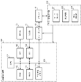
- a hardware configuration of a numerical controller 100 that controls the wire electric discharge machine 200 will be described with reference to FIG.
- the wire electric discharge machine 200 is given as an example of the present disclosure.
- the present disclosure shall be applicable to electrical discharge machining in general, including die-sinking electrical discharge machining.
- a CPU 111 included in the numerical controller 100 is a processor that controls the numerical controller 100 as a whole.
- the CPU 111 reads the system program processed in the ROM 112 via the bus 122 and controls the entire numerical controller 100 according to the system program.
- the RAM 113 temporarily stores calculation data, display data, various data input by the user via the input unit 71, and the like.
- the display unit 70 is a monitor attached to the numerical controller 100 or the like.
- the display unit 70 displays an operation screen, a setting screen, and the like of the numerical controller 100 .
- the input unit 71 is integrated with the display unit 70 or is a keyboard, touch panel, or the like that is separate from the display unit 70 .
- the user operates the input unit 71 to perform input to the screen displayed on the display unit 70 .
- the display unit 70 and the input unit 71 may be mobile terminals.
- the non-volatile memory 114 is, for example, a memory that is backed up by a battery (not shown) so that the memory state is retained even when the power of the numerical controller 100 is turned off.
- the nonvolatile memory 114 stores programs read from external devices via an interface (not shown), programs input via the input unit 71, and various data ( For example, setting parameters acquired from the machine tool 200, etc.) are stored. Programs and various data stored in the non-volatile memory 114 may be developed in the RAM 113 at the time of execution/use. Various system programs are pre-written in the ROM 112 .
- a controller 40 that controls the wire or table of the wire electric discharge machine 200 converts the axis movement command from the CPU 111 into a pulse signal and outputs it to the driver 41 .
- the driver 41 converts the pulse signal into current to drive the servo motor of the wire electric discharge machine 200 .
- the servomotor moves the wire and table under the control of the numerical controller 100 . By controlling the servomotor, it is possible to control the discharge gap and wire speed, which will be described later.
- the machining power supply 202 applies a voltage between the upper and lower feeders and the workpiece.
- the wire electric discharge machine 200 performs electric discharge machining on a work by generating electric discharge between a work mounted on a table and a wire electrode. The voltage and current applied to the wire change depending on the processing conditions described later.
- the discharge detection unit 203 measures the waveforms of the discharge voltage and the discharge current between the electrodes.
- the discharge detector 203 is, for example, an oscilloscope or a current sensor.
- the oscilloscope can grasp the discharge phenomenon occurring between poles.
- the current sensor measures the discharge current flowing through the power supply line.
- Numerical controller 100 adjusts the speed of the wire based on the discharge voltage and discharge current obtained from discharge detection unit 203, whether the discharge is normal, short-circuited, or continuous discharge.
- FIG. 2 is a block diagram of the numerical controller 100.
- the numerical control device 100 includes a machining program storage unit 11, a machining program analysis unit 12, a correction path creation unit 13, an excess cutting determination unit 14, an avoidance route creation unit 15, an unmachined path detection unit 16, a machining condition change unit 17, a machining A condition storage unit 18 and an interpolation processing unit 19 are provided.
- the machining program analysis section 12 creates a program path based on the machining program stored in the machining program storage section 11 .
- the program path varies depending on the machining process.
- FIG. 3 shows an example program path.
- the first machining process is rough machining
- the second machining process is semi-finishing (first time)
- the third machining process is semi-finishing (second time)
- the fourth machining process is final finishing. Finishing margins are often set from roughing to semi-finishing.
- the program path is shifted by the finishing margin. In general, a large finishing margin is left during rough machining, a small finishing margin is reduced during semi-finishing, and a finishing margin is zero during final finishing.
- the correction path creation unit 13 corrects the program path based on the wire diameter correction amount.
- the wire diameter correction amount is the processing radius of the wire.
- a route (correction route) is created by shifting the program route by the wire diameter correction amount.
- the wire diameter correction amount differs depending on the processing conditions. In general, the wire diameter correction amount for rough machining is large, and the wire diameter correction amount for final finishing is small.
- the excessive cutting determination unit 14 determines whether or not there is a portion in which excessive cutting occurs in the route after wire diameter correction.
- FIG. 4 shows the relationship between the machining radius and excess cutting depth.
- processing is performed in a straight line from the right side of the drawing to the left side of the drawing, and processing is performed diagonally from point A to the lower right side of the drawing.
- Excessive cutting occurs at point B when machining along the corrected path.
- FIG. 4B when the machining conditions are changed to reduce the voltage and current, the machining radius of the wire is reduced. Excessive depth of cut does not occur when the machining radius is small. In rough machining, the machining radius is large and the finishing margin is large, so overcutting is likely to occur and unmachined portions are likely to occur.
- the avoidance route creation unit 15 creates a route (avoidance route) that avoids excessive cutting.
- FIG. 5 is an example of an avoidance route.
- an avoidance path that avoids drilling is created.
- the avoidance path is not created and the correction path is adopted.
- the avoidance path is not created and the correction path is adopted.
- the raw route detection unit 16 detects the raw route by comparing the correction route and the avoidance route.
- the unprocessed route detection unit 16 stores information about the unprocessed portion (unprocessed portion related information).
- the processing condition changing unit 17 reads the unprocessed portion related information in the pre-processing, and selects processing conditions suitable for the processed shape of the unprocessed portion.
- (1) to (3) are the processing condition selection procedure.
- the machining condition changing unit 17 compares the correction path of the current machining and the avoidance path of the pre-machining to determine the shape of the unmachined part.
- the machining condition changing unit 17 determines whether to machine the rough-machined unmachined portion in the current machining for the first time.
- the machining condition changing unit 17 changes the machining conditions when all the conditions (1) to (3) are satisfied.
- the numerical controller 100 stores machining conditions as shown in FIG. Machining conditions include normal machining conditions such as rough machining, semi-finishing (first time), semi-finishing (second time), and final finishing, and machining conditions for unmachined portions. "Voltage”, “on time”, “feed rate”, “wire diameter correction amount” and the like are set for each machining condition.
- Processing conditions for unprocessed portions are set for each shape, such as "for corners” and “for grooves.”
- the machining condition “S21” is for “corners” and the machining condition “S22” is for “grooves.”
- the machining condition changing unit 17 compares the correction path of the previous machining and the avoidance path of the previous machining, determines the machining shape, and reads the machining conditions corresponding to the machining path. In the example of the present disclosure, the machining condition changing unit 17 reads the "grooving" machining condition "S22".
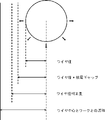
- the machining condition changing unit 17 determines whether or not excessive cutting occurs under the read machining conditions. As shown in FIG. 7, there is a gap called the “discharge gap" between the wire and the work surface. A “discharge gap” is a gap in which a discharge occurs. Changing the machining conditions changes the size of the "discharge gap". The machining radius corresponds to "wire diameter+discharge gap". “Wire diameter” is the radius of the wire to be processed. When changing the wire between roughing and finishing, the “wire diameter” also changes. The “wire diameter correction amount”, the "wire diameter+discharge gap", and the “machining radius” are substantially equal. If the machining conditions are changed, the machining radius will change and there is a possibility that an excessive interrupt will occur. In order to avoid this, the machining condition changing unit 17 determines whether or not excessive cutting occurs under the new machining conditions. If overcutting does not occur, the current machining conditions are changed to the machining conditions for the unmachined portion.
- the discharge gap is kept substantially constant during electrical discharge machining.
- the numerical controller 100 performs feedback control to control the speed of the wire and keep the discharge gap constant. A short circuit occurs when the distance between the wire and the workpiece is too close. When the wire speed decreases due to a mismatch between the machining conditions and the machining amount, the numerical controller 100 reduces the wire speed to keep the discharge gap constant.
- the change of processing conditions for the unprocessed portion will be described.
- the numerical controller 100 determines that overcutting occurs, the numerical controller 100 creates an avoidance path for avoiding overcutting.
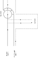
- the wire moves along the avoidance path and a raw part is generated (Fig. 8A).
- the semi-finishing first time
- machining is performed under the finishing machining condition "S2: semi-finishing (first time)" (Fig. 8B).
- S2 semi-finishing (first time)
- the numerical controller 100 starts processing to change the machining conditions.
- the numerical controller 100 compares the pre-machining correction path and the pre-machining avoidance path to determine the machining shape.
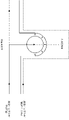
- the numerical controller 100 selects the machining condition "S22: unmachined portion (for groove)" as the machining condition corresponding to the machined shape, and determines whether or not excessive cutting occurs under this machining condition. When the numerical control device 100 determines that excessive cutting does not occur, the machining conditions are changed to machine the unmachined portion (FIG. 8C).
- the machining conditions are switched between the outward and return passes.
- an unmachined portion is machined on the forward pass (FIG. 9A)
- a portion that has already been machined is finished by the return pass (FIG. 9B). Therefore, the processing conditions are switched to those for the forward pass and the return pass.
- the machining condition "S22: unmachined portion (for groove)” is selected in the forward pass, and the machining condition is switched to "S2: semi-finishing (first time)" in the return pass.
- FIG. 11 shows conventional wire electrical discharge machining.
- an unmachined portion is generated in the grooving of rough machining.
- machining is started under the machining condition "S2: semi-finishing (first time)" (Fig. 11A).
- S2 intermediate finishing (first time)
- the machining amount of the unmachined portion is larger than the machining amount of the finish machining, causing a mismatch between the actual machining and the machining conditions, resulting in a decrease in wire speed.
- the distance between the wire and the workpiece is shortened, increasing the possibility of wire short-circuiting.
- the command speed of feedback control also decreases in order to keep the discharge gap constant.
- the numerical control device 100 of the present disclosure detects the occurrence of an unprocessed portion in the pre-machining, and changes the processing conditions to those suitable for the unprocessed portion when processing the unprocessed portion in the current processing. As a result, it is possible to prevent a decrease in machining speed and frequent occurrence of short circuits. In the present disclosure, by changing the machining conditions, determination is made so as not to cause excessive cutting even if the machining radius of wire electric discharge machining increases.
- the machining program analysis unit 12 analyzes the machining program and creates a program path (step S1).
- step S1 a program path for rough machining, a program path for semi-finishing, and a program path for final finishing may be created.
- a program path for rough machining is created.
- the corrected path creation unit 13 corrects the program path based on the wire diameter correction amount to create a corrected path (step S2).
- the excessive cutting determination unit determines whether or not there is a portion of the correction path in which excessive cutting occurs (step S3).
- the avoidance route creation unit 15 creates a route (avoidance route) for avoiding excessive cutting (step S5).
- the unprocessed route detection unit 16 detects an unprocessed portion by comparing the correction route and the avoidance route.
- the unprocessed route detection unit 16 stores information related to the unprocessed portion, such as position information of the unprocessed portion (step S6).
- step S7 When continuing machining (step S7; Yes), the numerical controller 100 shifts the process to step S1 and creates a program path.
- step S7; No When finishing the processing (step S7; No), the process of recording information related to the unprocessed portion is ended.
- Pre-processing means a processing step prior to the current processing step.
- the processing condition changing unit 17 determines whether or not the unprocessed portion in the pre-processing is approached. If the current machining is not approaching the unmachined portion (step S11; No), monitoring is continued. When the current machining approaches the unmachined portion (step S11; Yes), the machining condition changing unit 17 determines the machining shape of the unmachined portion (step S12). Machining shapes include, but are not limited to, "groove” and "corner”.
- the machining condition changing unit 17 determines whether the part is rough-machined or not. Since the unmachined portion of rough machining has a large amount of machining, machining conditions that require a larger amount of machining than finish machining are suitable. If the unmachined portion is rough-machined (step S13; Yes), the machining condition changing unit 17 selects machining conditions suitable for the machining shape of the unmachined portion from the machining condition storage unit 18 (step S14). The machining condition changing unit 17 determines whether or not excessive cutting occurs under machining conditions corresponding to the machining shape of the unmachined portion (step S15).
- step S16; Yes If excessive cutting occurs (step S16; Yes), the process proceeds to step S11 without changing the machining conditions. If excessive cutting does not occur (step S16; No), the machining conditions are changed (step 17). Here, when the current machining process is finished (step S18; Yes), the machining condition change process is finished. While the current machining process continues (step S18; No), the process proceeds to step S11 to continue the process of changing the machining conditions.
- the numerical control device 100 of the present disclosure in wire electric discharge machining that repeats machining a plurality of times to machine one workpiece, if there is an unmachined portion in the previous machining, changes the shape of the unmachined portion. Then, a machining condition suitable for the shape of the unmachined portion is selected, and it is judged whether or not excessive cutting occurs when machining is performed under this machining condition. When overcutting occurs, the numerical controller 100 does not change the machining conditions. If overcutting does not occur, change the machining conditions.
- the numerical controller 100 may be provided with a function of determining whether or not the current machining is the final finish, and not changing the machining conditions if it is the final finish.
- a function may be provided to change the machining conditions on the forward pass and not to change the machining conditions on the return pass. If the width of the groove in "groove machining" is equal to "wire diameter+discharge gap", a function that does not change the machining conditions may be provided.
- Wire electric discharge machining is electric discharge machining in which a tool electrode is a wire.
- the tool electrode may be a conductor (metal) in a shape other than a wire.
- Sinking EDM uses electrodes instead of wires.
- a correction amount for general electric discharge machining is defined as an electrode shape correction amount.
- the electrode shape correction amount is the electrode shape+discharge gap amount.
- the wire diameter correction amount is a kind of electrode shape correction amount.
- the electrode shape correction amount is used to correct the program path, create an avoidance path, and determine excessive cutting.
Landscapes
- Engineering & Computer Science (AREA)
- Physics & Mathematics (AREA)
- Automation & Control Theory (AREA)
- Human Computer Interaction (AREA)
- Manufacturing & Machinery (AREA)
- General Physics & Mathematics (AREA)
- Chemical & Material Sciences (AREA)
- Chemical Kinetics & Catalysis (AREA)
- Electrochemistry (AREA)
- Mechanical Engineering (AREA)
- Geometry (AREA)
- Electrical Discharge Machining, Electrochemical Machining, And Combined Machining (AREA)
Priority Applications (5)
| Application Number | Priority Date | Filing Date | Title |
|---|---|---|---|
| JP2023514259A JP7636524B2 (ja) | 2021-04-15 | 2021-04-15 | 数値制御装置及びコンピュータが読み取り可能な記憶媒体 |
| CN202180096817.1A CN117120198B (zh) | 2021-04-15 | 2021-04-15 | 数值控制装置以及计算机可读取的存储介质 |
| PCT/JP2021/015521 WO2022219760A1 (ja) | 2021-04-15 | 2021-04-15 | 数値制御装置及びコンピュータが読み取り可能な記憶媒体 |
| EP21936961.8A EP4324584A4 (en) | 2021-04-15 | 2021-04-15 | Numerical value control device and computer-readable storage medium |
| US18/286,154 US20240184264A1 (en) | 2021-04-15 | 2021-04-15 | Numerical control device and computer readable storage medium |
Applications Claiming Priority (1)
| Application Number | Priority Date | Filing Date | Title |
|---|---|---|---|
| PCT/JP2021/015521 WO2022219760A1 (ja) | 2021-04-15 | 2021-04-15 | 数値制御装置及びコンピュータが読み取り可能な記憶媒体 |
Publications (2)
| Publication Number | Publication Date |
|---|---|
| WO2022219760A1 true WO2022219760A1 (ja) | 2022-10-20 |
| WO2022219760A9 WO2022219760A9 (ja) | 2023-08-10 |
Family
ID=83640217
Family Applications (1)
| Application Number | Title | Priority Date | Filing Date |
|---|---|---|---|
| PCT/JP2021/015521 Ceased WO2022219760A1 (ja) | 2021-04-15 | 2021-04-15 | 数値制御装置及びコンピュータが読み取り可能な記憶媒体 |
Country Status (5)
| Country | Link |
|---|---|
| US (1) | US20240184264A1 (https=) |
| EP (1) | EP4324584A4 (https=) |
| JP (1) | JP7636524B2 (https=) |
| CN (1) | CN117120198B (https=) |
| WO (1) | WO2022219760A1 (https=) |
Cited By (2)
| Publication number | Priority date | Publication date | Assignee | Title |
|---|---|---|---|---|
| WO2024111031A1 (ja) * | 2022-11-21 | 2024-05-30 | ファナック株式会社 | 加工状態予測装置及び加工制御装置 |
| TWI865252B (zh) * | 2023-12-14 | 2024-12-01 | 國立臺灣師範大學 | 等能量密度的放電加工設備及方法 |
Citations (5)
| Publication number | Priority date | Publication date | Assignee | Title |
|---|---|---|---|---|
| JPH01228727A (ja) * | 1988-03-03 | 1989-09-12 | Mitsubishi Electric Corp | ワイヤ放電加工方法 |
| JPH04176516A (ja) * | 1990-11-09 | 1992-06-24 | Mitsubishi Electric Corp | ワイヤ放電加工におけるセカンドカット加工方法及びセカンドカット加工制御装置 |
| JPH06262438A (ja) * | 1992-07-06 | 1994-09-20 | Ind Elektronik Agie Losone Locarno:Ag | 精密ワイヤ放電加工方法および装置 |
| WO2010050014A1 (ja) * | 2008-10-29 | 2010-05-06 | 三菱電機株式会社 | ワイヤ放電加工装置 |
| JP5622977B1 (ja) | 2013-12-19 | 2014-11-12 | 三菱電機株式会社 | ワイヤ放電加工装置、ワイヤ放電加工方法および制御装置 |
Family Cites Families (17)
| Publication number | Priority date | Publication date | Assignee | Title |
|---|---|---|---|---|
| JPH01240219A (ja) * | 1988-03-22 | 1989-09-25 | Mitsubishi Electric Corp | ワイヤ放電加工方法 |
| DE4116868C2 (de) * | 1991-05-23 | 1995-07-27 | Agie Ag Ind Elektronik | Verfahren zur Bearbeitung von Werkstücken, insbesondere zur funkenerosiven Bearbeitung von Werkstücken mittels eines Drahtes |
| US5418344A (en) * | 1992-10-20 | 1995-05-23 | Mitsubishi Denki Kabushiki Kaisha | Method and apparatus for wire-cutting electrical discharge machining of a corner |
| JPH0819918A (ja) * | 1994-07-07 | 1996-01-23 | Mitsubishi Electric Corp | ワイヤ放電加工方法及びその装置 |
| JP3547618B2 (ja) * | 1998-05-25 | 2004-07-28 | 三菱電機株式会社 | 放電加工装置および放電加工方法、並びに放電加工方法をコンピュータに実行させるプログラムを格納した、コンピュータが読取可能な記録媒体 |
| JP2000280122A (ja) | 1999-03-30 | 2000-10-10 | Sodick Co Ltd | ワイヤカット放電加工方法 |
| CN1260031C (zh) * | 2000-10-27 | 2006-06-21 | 三菱电机株式会社 | 线切割放电加工方法及装置 |
| JP4588702B2 (ja) * | 2004-03-01 | 2010-12-01 | 三菱電機株式会社 | 放電加工装置 |
| US8829383B2 (en) * | 2008-07-03 | 2014-09-09 | Mitsubishi Electric Corporation | Wire electric discharge machine and wire electric discharge machining method |
| WO2011036924A1 (ja) * | 2009-09-24 | 2011-03-31 | 三菱電機株式会社 | ワイヤ放電加工装置、ワイヤ放電加工方法、薄板製造方法および半導体ウエハ製造方法 |
| JP5689431B2 (ja) * | 2012-03-12 | 2015-03-25 | ファナック株式会社 | プログラム指令によって加工経路の補正を行うワイヤ放電加工機の制御装置 |
| US9632497B2 (en) * | 2012-04-27 | 2017-04-25 | Mitsubishi Electric Corporation | Machining-program generating apparatus, machining-program generating method, and recording medium |
| CN104853872B (zh) * | 2013-12-10 | 2017-07-14 | 三菱电机株式会社 | 线电极放电加工装置、线电极放电加工方法以及控制装置 |
| JP5837031B2 (ja) * | 2013-12-26 | 2015-12-24 | ファナック株式会社 | 凹円弧コーナ部の経路補正を行うワイヤ放電加工機およびワイヤ放電加工機の加工経路作成装置およびワイヤ放電加工機の加工方法 |
| JP5855692B2 (ja) * | 2014-02-26 | 2016-02-09 | ファナック株式会社 | コーナ形状補正機能を有するワイヤ放電加工機 |
| CN106573322B (zh) * | 2014-08-26 | 2018-10-09 | 三菱电机株式会社 | Cam软件及线电极放电加工机 |
| JP6760998B2 (ja) * | 2018-06-29 | 2020-09-23 | ファナック株式会社 | ワイヤ放電加工機の制御装置 |
-
2021
- 2021-04-15 WO PCT/JP2021/015521 patent/WO2022219760A1/ja not_active Ceased
- 2021-04-15 JP JP2023514259A patent/JP7636524B2/ja active Active
- 2021-04-15 US US18/286,154 patent/US20240184264A1/en active Pending
- 2021-04-15 CN CN202180096817.1A patent/CN117120198B/zh active Active
- 2021-04-15 EP EP21936961.8A patent/EP4324584A4/en active Pending
Patent Citations (5)
| Publication number | Priority date | Publication date | Assignee | Title |
|---|---|---|---|---|
| JPH01228727A (ja) * | 1988-03-03 | 1989-09-12 | Mitsubishi Electric Corp | ワイヤ放電加工方法 |
| JPH04176516A (ja) * | 1990-11-09 | 1992-06-24 | Mitsubishi Electric Corp | ワイヤ放電加工におけるセカンドカット加工方法及びセカンドカット加工制御装置 |
| JPH06262438A (ja) * | 1992-07-06 | 1994-09-20 | Ind Elektronik Agie Losone Locarno:Ag | 精密ワイヤ放電加工方法および装置 |
| WO2010050014A1 (ja) * | 2008-10-29 | 2010-05-06 | 三菱電機株式会社 | ワイヤ放電加工装置 |
| JP5622977B1 (ja) | 2013-12-19 | 2014-11-12 | 三菱電機株式会社 | ワイヤ放電加工装置、ワイヤ放電加工方法および制御装置 |
Non-Patent Citations (1)
| Title |
|---|
| See also references of EP4324584A4 |
Cited By (2)
| Publication number | Priority date | Publication date | Assignee | Title |
|---|---|---|---|---|
| WO2024111031A1 (ja) * | 2022-11-21 | 2024-05-30 | ファナック株式会社 | 加工状態予測装置及び加工制御装置 |
| TWI865252B (zh) * | 2023-12-14 | 2024-12-01 | 國立臺灣師範大學 | 等能量密度的放電加工設備及方法 |
Also Published As
| Publication number | Publication date |
|---|---|
| EP4324584A4 (en) | 2025-02-19 |
| WO2022219760A9 (ja) | 2023-08-10 |
| US20240184264A1 (en) | 2024-06-06 |
| EP4324584A1 (en) | 2024-02-21 |
| CN117120198B (zh) | 2026-03-13 |
| JP7636524B2 (ja) | 2025-02-26 |
| CN117120198A (zh) | 2023-11-24 |
| JPWO2022219760A1 (https=) | 2022-10-20 |
Similar Documents
| Publication | Publication Date | Title |
|---|---|---|
| JPWO2010001472A1 (ja) | ワイヤ放電加工装置、及びワイヤ放電加工方法 | |
| KR102577377B1 (ko) | 와이어 방전 가공기 및 가공 프로그램 편집 장치 | |
| JP2006123065A (ja) | ワイヤ放電加工機の制御装置 | |
| KR920006654B1 (ko) | 와이어 커트 방전 가공기 | |
| CN103286397B (zh) | 减少加工损伤的电火花线切割机以及电火花线切割方法 | |
| US5021622A (en) | Wire cut electrical discharge machine | |
| WO2022219760A1 (ja) | 数値制御装置及びコンピュータが読み取り可能な記憶媒体 | |
| JP2005066738A (ja) | ワイヤカット放電加工機の加工制御方法 | |
| JP4569973B2 (ja) | 放電加工装置及び方法、並びに放電発生を判別する方法 | |
| US9442479B2 (en) | Wire electric discharge machine controller, wire electric discharge machine, and wire electric discharge machining method | |
| EP1909153B1 (en) | Apparatus for creating a turning program | |
| JP7372191B2 (ja) | プログラム編集装置、ワイヤ放電加工機およびプログラム編集方法 | |
| JP7364358B2 (ja) | ワイヤ放電加工機およびワイヤ放電加工方法 | |
| US10376977B2 (en) | Control device, wire electrical discharge machine, program editing apparatus, and control method | |
| JPH0253526A (ja) | ワイヤカット放電加工機 | |
| JP2004122260A (ja) | ワイヤ放電加工機 | |
| JPH01501051A (ja) | ワイヤカツト放電加工機 | |
| JP2885228B2 (ja) | ワイヤ放電加工方法及び装置 | |
| JPH0724645A (ja) | ワイヤ放電加工装置 | |
| JPH1076429A (ja) | ワイヤ放電加工装置及びその加工方法 | |
| JP3103675B2 (ja) | 放電加工方法およびその装置 | |
| JP2541205B2 (ja) | ワイヤカツト放電加工機 | |
| JPH0732968B2 (ja) | ワイヤカット放電加工機 | |
| WO2022097596A9 (ja) | ワイヤ放電加工機、及び、ワイヤ放電加工機の制御方法 | |
| CN119426738A (zh) | 电极丝放电加工装置和电极丝放电加工方法 |
Legal Events
| Date | Code | Title | Description |
|---|---|---|---|
| 121 | Ep: the epo has been informed by wipo that ep was designated in this application |
Ref document number: 21936961 Country of ref document: EP Kind code of ref document: A1 |
|
| WWE | Wipo information: entry into national phase |
Ref document number: 2023514259 Country of ref document: JP |
|
| WWE | Wipo information: entry into national phase |
Ref document number: 18286154 Country of ref document: US |
|
| WWE | Wipo information: entry into national phase |
Ref document number: 2021936961 Country of ref document: EP |
|
| NENP | Non-entry into the national phase |
Ref country code: DE |
|
| ENP | Entry into the national phase |
Ref document number: 2021936961 Country of ref document: EP Effective date: 20231115 |