WO2022210347A1 - センサ素子及びガスセンサ - Google Patents
センサ素子及びガスセンサ Download PDFInfo
- Publication number
- WO2022210347A1 WO2022210347A1 PCT/JP2022/014339 JP2022014339W WO2022210347A1 WO 2022210347 A1 WO2022210347 A1 WO 2022210347A1 JP 2022014339 W JP2022014339 W JP 2022014339W WO 2022210347 A1 WO2022210347 A1 WO 2022210347A1
- Authority
- WO
- WIPO (PCT)
- Prior art keywords
- voltage
- gas
- pump
- electrode
- cell
- Prior art date
- Legal status (The legal status is an assumption and is not a legal conclusion. Google has not performed a legal analysis and makes no representation as to the accuracy of the status listed.)
- Ceased
Links
Images






Classifications
-
- G—PHYSICS
- G01—MEASURING; TESTING
- G01N—INVESTIGATING OR ANALYSING MATERIALS BY DETERMINING THEIR CHEMICAL OR PHYSICAL PROPERTIES
- G01N27/00—Investigating or analysing materials by the use of electric, electrochemical, or magnetic means
- G01N27/26—Investigating or analysing materials by the use of electric, electrochemical, or magnetic means by investigating electrochemical variables; by using electrolysis or electrophoresis
- G01N27/416—Systems
- G01N27/417—Systems using cells, i.e. more than one cell and probes with solid electrolytes
-
- G—PHYSICS
- G01—MEASURING; TESTING
- G01N—INVESTIGATING OR ANALYSING MATERIALS BY DETERMINING THEIR CHEMICAL OR PHYSICAL PROPERTIES
- G01N27/00—Investigating or analysing materials by the use of electric, electrochemical, or magnetic means
- G01N27/26—Investigating or analysing materials by the use of electric, electrochemical, or magnetic means by investigating electrochemical variables; by using electrolysis or electrophoresis
- G01N27/416—Systems
- G01N27/417—Systems using cells, i.e. more than one cell and probes with solid electrolytes
- G01N27/419—Measuring voltages or currents with a combination of oxygen pumping cells and oxygen concentration cells
-
- G—PHYSICS
- G01—MEASURING; TESTING
- G01N—INVESTIGATING OR ANALYSING MATERIALS BY DETERMINING THEIR CHEMICAL OR PHYSICAL PROPERTIES
- G01N33/00—Investigating or analysing materials by specific methods not covered by groups G01N1/00 - G01N31/00
- G01N33/0004—Gaseous mixtures, e.g. polluted air
- G01N33/0009—General constructional details of gas analysers, e.g. portable test equipment
- G01N33/0027—General constructional details of gas analysers, e.g. portable test equipment concerning the detector
- G01N33/0036—General constructional details of gas analysers, e.g. portable test equipment concerning the detector specially adapted to detect a particular component
- G01N33/0037—NOx
Definitions
- the present invention relates to sensor elements and gas sensors.
- Patent Literature 1 describes a gas sensor having a long plate-like sensor element formed by laminating a plurality of oxygen ion conductive solid electrolyte layers.
- FIG. 13 shows a schematic cross-sectional view schematically showing an example of the configuration of such a conventional gas sensor 900.
- this gas sensor 900 has a sensor element 901 .
- This sensor element 901 is an element having a structure in which oxygen ion conductive solid electrolyte layers 911 to 916 are laminated.
- a measured gas flow section for introducing a measured gas is formed between the lower surface of the solid electrolyte layer 916 and the upper surface of the solid electrolyte layer 914.
- An internal cavity 920, a second internal cavity 940, and a third internal cavity 961 are provided.
- An inner pump electrode 922 is arranged in the first internal cavity 920, an auxiliary pump electrode 951 is arranged in the second internal cavity 940, and a measuring electrode 944 is arranged in the third internal cavity 961.
- An outer pump electrode 923 is arranged on the upper surface of the solid electrolyte layer 916 .
- a reference electrode 942 is arranged in contact with a reference gas (for example, the air) that serves as a reference for detecting the specific gas concentration in the gas to be measured.
- a main pump cell 921 is composed of the inner pump electrode 922, the outer pump electrode 923, and the solid electrolyte layers 914-916.
- a measuring pump cell 941 is composed of the measuring electrode 944, the outer pump electrode 923, and the solid electrolyte layers 914-916.
- the measuring electrode 944 , the reference electrode 942 , and the solid electrolyte layers 914 and 913 constitute an oxygen partial pressure detecting sensor cell 982 for controlling the measuring pump.
- a Vref detection sensor cell 983 is composed of the outer pump electrode 923, the reference electrode 942, and the solid electrolyte layers 913-916.
- a reference gas regulation pump cell 990 is composed of the outer pump electrode 923, the reference electrode 942, and the solid electrolyte layers 913-916.
- the main pump cell 921 pumps oxygen between the first internal cavity 920 and the outside of the sensor element.
- Oxygen is pumped in or out between the second internal cavity 940 and the outside of the sensor element to adjust the oxygen concentration in the measured gas flow portion. NOx in the gas under measurement after the oxygen concentration is adjusted is reduced around the measuring electrode 944 .
- the voltage Vp2 applied to the measuring pump cell 941 is feedback-controlled so that the voltage V2 generated at the measuring pump controlling oxygen partial pressure detecting sensor cell 982 becomes a predetermined target value, and the measuring pump cell 941 becomes the measuring electrode. Pump oxygen around 944.
- the reference gas regulating pump cell 990 also pumps oxygen around the reference electrode 942 by applying a voltage Vp3 between the reference electrode 942 and the outer pump electrode 923 to cause a pump current Ip3 to flow.
- the Vref detection sensor cell 983 develops a voltage Vref between the outer pump electrode 923 and the reference electrode 942 . The oxygen concentration in the gas to be measured outside the sensor element 901 can be detected from this voltage Vref.
- the voltage V2 of the oxygen partial pressure detection sensor cell 982 for controlling the measurement pump described above will change.
- the oxygen concentration detection accuracy may be low.
- the present invention has been made in order to solve such problems.
- the main purpose is
- the present invention employs the following means to achieve the above-mentioned main purpose.
- the sensor element of the present invention is A sensor element for detecting a specific gas concentration in a gas to be measured, an element body including a solid electrolyte layer with oxygen ion conductivity and having therein a measured gas flow section for introducing and circulating the measured gas; a reference gas introduction part disposed inside the element main body and into which a reference gas serving as a reference for detecting the specific gas concentration in the gas to be measured is introduced; A reference for pumping oxygen around the pump reference electrode, which has a pump reference electrode disposed inside the element body so as to be in contact with the reference gas introduced into the reference gas introduction portion.
- a gas regulating pump cell a voltage reference electrode disposed inside the element body so as to be in contact with the reference gas introduced into the reference gas introduction portion; and a voltage reference electrode disposed inside or outside the element body so as to be in contact with the measured gas.
- a sensor cell having a measured gas side electrode disposed thereon, the sensor cell generating a voltage based on the oxygen concentration around the measured gas side electrode; is provided.
- This sensor element includes a reference gas regulation pump cell and a sensor cell.
- the reference gas adjustment pump cell pumps oxygen around the pumping reference electrode, thereby compensating for a decrease in the oxygen concentration of the reference gas in the reference gas introduction section.
- the oxygen concentration around the measured gas side electrode can be detected by the voltage of the sensor cell.
- a pump reference electrode forming part of the reference gas adjustment pump cell and a voltage reference electrode forming part of the sensor cell are disposed in the element body of the sensor element. That is, in this sensor element, a reference electrode for pumping and a reference electrode for voltage are separately provided as electrodes that come into contact with the reference gas in the reference gas introduction section.
- the voltage reference electrode does not receive the pump current when the reference gas adjustment pump cell performs oxygen pumping, so the voltage of the sensor cell is The voltage drop of the voltage reference electrode due to the pump current is not included.
- the voltage of the sensor cell becomes a value that more accurately corresponds to the oxygen concentration around the electrode on the side of the gas to be measured, so that the oxygen concentration detection accuracy using the sensor cell is improved.
- this sensor element it is possible to suppress the deterioration of the oxygen concentration detection accuracy due to the pump current at the time of pumping oxygen while pumping oxygen into the reference gas introduction portion.
- the reference gas adjustment pump cell is a pumping source disposed inside or outside the element main body so as to draw oxygen around the reference electrode for pumping and to come into contact with the gas to be measured. It may have electrodes.
- the reference gas regulation pump cell may also pump oxygen from around the pump reference electrode.
- the sensor element of the present invention includes a measuring pump cell for pumping out oxygen generated in the measuring chamber of the measured gas flow section due to the specific gas, and the measured gas side electrode A measuring electrode disposed in a chamber, wherein the sensor cell may be a measuring sensor cell that produces a voltage based on the oxygen concentration in the measuring chamber.
- the sensor cell may be a measuring sensor cell that produces a voltage based on the oxygen concentration in the measuring chamber.
- the voltage of the sensor cell for measurement becomes a value corresponding to the oxygen concentration in the measurement chamber with higher accuracy.
- the detection accuracy of the oxygen concentration in the used measurement chamber is improved.
- the voltage of the measurement sensor cell affects the detection accuracy of the specific gas concentration in the gas under measurement by being used to control the measurement pump cell, for example. Therefore, by improving the detection accuracy of the oxygen concentration in the measurement chamber using the measurement sensor cell, the detection accuracy of the specific gas concentration is improved.
- the sensor element of the present invention includes an adjustment electrode arranged in the oxygen concentration adjustment chamber on the upstream side of the measurement chamber in the measurement gas circulation section, and an adjustment electrode arranged outside the element main body.
- An outer sensor cell having the provided outer voltage electrode and the voltage reference electrode and generating a voltage based on the oxygen concentration in the gas to be measured outside the element main body may be provided.
- a pump outer electrode forming a part of the regulation chamber pump cell and a voltage outer electrode forming a part of the outer sensor cell are arranged outside the element body.
- a pump outer electrode and a voltage outer electrode are separately provided outside the element body. Therefore, when one electrode serves both as the pump outer electrode and the voltage outer electrode (for example, in the sensor element 901 shown in FIG. 13, the outer pump electrode 923 serves as the electrode of the main pump cell 921 and the Vref detection sensor cell. 983), the voltage of the external sensor cell does not match the pump current when the control chamber pump cell pumps out or pumps oxygen. The resulting voltage drop of the outer voltage electrode is not included. As a result, the voltage of the outer sensor cell becomes a value that more accurately corresponds to the oxygen concentration in the gas to be measured outside the element body, so the accuracy of detecting the oxygen concentration in the gas to be measured using the outer sensor cell is improved. do.
- the pump current of the reference gas regulation pump cell does not flow through the voltage reference electrode. Therefore, the voltage of the outer sensor cell is the voltage between the outer voltage electrode and the voltage reference electrode, and no pump current flows through either of the voltage outer electrode or the voltage reference electrode. Therefore, the voltage of the outer sensor cell becomes a value corresponding to the oxygen concentration of the gas to be measured on the outer side of the element body with higher accuracy.
- a first gas sensor of the present invention comprises: a sensor element comprising the measuring pump cell and the measuring sensor cell described above; a measuring pump cell control unit that causes the measuring pump cell to pump oxygen from the measuring chamber by feedback-controlling the measuring pump cell so that the voltage of the measuring sensor cell becomes a target voltage; is provided.
- the detection accuracy of the oxygen concentration in the measurement chamber using the measurement sensor cell of the sensor element is improved. is feedback-controlled, the oxygen concentration in the measurement chamber can be accurately adjusted to the oxygen concentration corresponding to the target voltage. At this time, the concentration of the specific gas is detected based on the pump current flowing through the measuring pump cell, so the detection accuracy of the concentration of the specific gas is also improved.
- the first gas sensor of the present invention causes the reference gas regulation pump cell to pump oxygen around the pump reference electrode by applying a control voltage that is repeatedly turned on and off to the reference gas regulation pump cell.
- the measurement pump cell control unit acquires the voltage of the measurement sensor cell while the control voltage that is repeatedly turned on and off is off, and the acquired voltage reaches the target
- the measuring pump cell may be feedback-controlled so as to obtain the voltage.
- the sensor element is provided with the pump reference electrode and the voltage reference electrode separately, so that the voltage reference electrode is used by the reference gas adjustment pump cell when pumping oxygen. no current flows.
- the control voltage applied to the reference gas regulating pump cell may influence the voltage of the measuring sensor cell.
- the measuring pump cell control section may acquire the voltage of the measuring sensor cell at a timing immediately before the control voltage that is repeatedly turned on and off is turned off next time. In this way, the influence of the control voltage on the voltage of the measuring sensor cell can be further suppressed.
- the second gas sensor of the present invention is a sensor element in which the pump outer electrode and the voltage outer electrode are separately provided; By controlling the adjustment chamber pump cell so that the oxygen concentration in the oxygen concentration adjustment chamber becomes a predetermined low concentration, the adjustment chamber pump cell pumps oxygen from the oxygen concentration adjustment chamber or to the oxygen concentration adjustment chamber.
- a pump cell control unit for the control room that causes the pumping of oxygen from an oxygen concentration detection unit that detects the oxygen concentration in the gas to be measured outside the element body based on the voltage of the outer sensor cell; is provided.
- the adjustment chamber pump cell control unit controls the adjustment chamber pump cell so that the oxygen concentration in the oxygen concentration adjustment chamber becomes a predetermined low concentration.
- the adjustment chamber pump cell control section reverses the direction in which the adjustment chamber pump cell moves oxygen. switch.
- the direction of the pump current flowing through the adjustment chamber pump cell is reversed. Therefore, if one electrode serves both the role of the outer electrode for pump and the outer electrode for voltage, the time required for the current change when the direction of the pump current flowing in the control chamber pump cell is switched to the opposite direction is caused.
- the change in the voltage of the outer sensor cell also slows down.
- the outer electrode for pump and the outer electrode for voltage are provided separately, so the voltage of the outer sensor cell is affected by the time required for the change in the pump current flowing through the control chamber pump cell. Therefore, the voltage change of the outer sensor cell does not slow down. That is, the responsiveness of the voltage of the outer sensor cell is less likely to decrease when the oxygen concentration in the gas to be measured is switched between a state higher than a predetermined low concentration and a state lower than the predetermined low concentration.
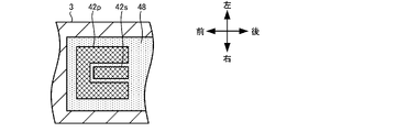
- FIG. 4 is a cross-sectional view of a pump reference electrode 42p and a voltage reference electrode 42s;
- FIG. 2 is a block diagram showing an electrical connection relationship between a control device 95 and each cell of a sensor element 101;
- FIG. 4 is an explanatory diagram showing an example of temporal change of voltage Vp3;
- FIG. 4 is an explanatory diagram showing an example of time change of voltage Vref;
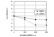
- Graph showing the relationship between the elapsed time of the endurance test and the NO output change rate.
- FIG. 4 is a graph showing changes in the response time of the voltage Vref before and after the atmospheric continuous test; 7 is a graph showing how the voltage Vref of Examples 2 and 3 changes over time after the continuous atmospheric test.
- FIG. 5 is a cross-sectional view of a pump reference electrode 42p and a voltage reference electrode 42s of a modified example;
- FIG. 5 is a cross-sectional view of a pump reference electrode 42p and a voltage reference electrode 42s of a modified example;
- FIG. 2 is a schematic cross-sectional view schematically showing an example of the configuration of a conventional gas sensor 900.
- FIG. 1 is a schematic cross-sectional view schematically showing an example of the configuration of a gas sensor 100 according to the first embodiment of the invention.
- FIG. 2 is a cross-sectional view of the pump reference electrode 42p and the voltage reference electrode 42s of the sensor element 101.
- FIG. 3 is a block diagram showing an electrical connection relationship between the control device 95 and each cell of the sensor element 101.
- the gas sensor 100 includes an elongated rectangular parallelepiped sensor element 101 and a control device 95 that controls the entire gas sensor 100 .
- the gas sensor 100 also includes an element sealing body (not shown) that encloses and fixes the sensor element 101, a bottomed cylindrical protective cover (not shown) that protects the front end of the sensor element 101, and the like.
- the sensor element 101 includes cells 21 , 41 , 50 , 80 to 83 , 90 and a heater section 70 .
- the gas sensor 100 is attached to a pipe such as an exhaust gas pipe of an internal combustion engine.
- the gas sensor 100 detects the concentration of specific gases such as NOx and ammonia in the gas to be measured, which is exhaust gas from an internal combustion engine.
- the gas sensor 100 measures the NOx concentration as the specific gas concentration.
- the longitudinal direction of the sensor element 101 (horizontal direction in FIG. 1) is defined as the front-rear direction, and the thickness direction of the sensor element 101 (vertical direction in FIG. 1) is defined as the vertical direction.
- the width direction of the sensor element 101 (the direction perpendicular to the front-back direction and the up-down direction) is defined as the left-right direction.
- FIG. 2 shows a partial cross section around the pump reference electrode 42p and the voltage reference electrode 42s when the third substrate layer 3 is cut along the front, back, left, and right.
- the sensor element 101 includes a first substrate layer 1, a second substrate layer 2, and a third substrate layer 3 each made of an oxygen ion conductive solid electrolyte layer such as zirconia (ZrO 2 ). , a first solid electrolyte layer 4, a spacer layer 5, and a second solid electrolyte layer 6, which are stacked in this order from the bottom as viewed in the drawing. Also, the solid electrolyte forming these six layers is dense and airtight.
- the sensor element 101 is manufactured by, for example, performing predetermined processing and circuit pattern printing on ceramic green sheets corresponding to each layer, laminating them, and firing them to integrate them.
- a gas introduction port 10 and a first diffusion control portion 11 are provided between the lower surface of the second solid electrolyte layer 6 and the upper surface of the first solid electrolyte layer 4 on the front end side (front end side) of the sensor element 101.
- the buffer space 12, the second diffusion rate-limiting portion 13, the first internal space 20, the third diffusion rate-limiting portion 30, the second internal space 40, the fourth diffusion rate-limiting portion 60, and the third internal space. 61 are formed adjacent to each other in a manner communicating with each other in this order.
- the gas introduction port 10, the buffer space 12, the first internal cavity 20, the second internal cavity 40, and the third internal cavity 61 are provided in the upper part provided by hollowing out the spacer layer 5.
- the space inside the sensor element 101 is defined by the lower surface of the second solid electrolyte layer 6 , the upper surface of the first solid electrolyte layer 4 in the lower portion, and the side surface of the spacer layer 5 in the lateral portion.
- Each of the first diffusion rate-controlling part 11, the second diffusion rate-controlling part 13, and the third diffusion rate-controlling part 30 is provided as two horizontally long slits (the opening has a longitudinal direction in a direction perpendicular to the drawing).
- the fourth diffusion rate-controlling part 60 is provided as one horizontally long slit (the opening has its longitudinal direction in the direction perpendicular to the drawing) formed as a gap with the lower surface of the second solid electrolyte layer 6 .
- a portion from the gas introduction port 10 to the third internal space 61 is also referred to as a measured gas flow portion.
- the sensor element 101 includes a reference gas introduction portion 49 for circulating a reference gas from the outside of the sensor element 101 to the pump reference electrode 42p and the voltage reference electrode 42s when measuring the NOx concentration.
- the reference gas introduction section 49 has a reference gas introduction space 43 and a reference gas introduction layer 48 .
- the reference gas introduction space 43 is a space provided inward from the rear end surface of the sensor element 101 .
- the reference gas introduction space 43 is provided between the upper surface of the third substrate layer 3 and the lower surface of the spacer layer 5 at a position defined by the side surface of the first solid electrolyte layer 4 .
- the reference gas introduction space 43 is open at the rear end surface of the sensor element 101, and the reference gas is introduced into the reference gas introduction space 43 through this opening.
- the reference gas introduction unit 49 introduces the reference gas introduced from the outside of the sensor element 101 into the pump reference electrode 42p and the voltage reference electrode 42s while imparting a predetermined diffusion resistance to the reference gas.
- the reference gas was the air in this embodiment.
- the reference gas introduction layer 48 is provided between the upper surface of the third substrate layer 3 and the lower surface of the first solid electrolyte layer 4 .
- the reference gas introduction layer 48 is a porous body made of ceramics such as alumina. A portion of the upper surface of the reference gas introduction layer 48 is exposed inside the reference gas introduction space 43 .
- the reference gas introduction layer 48 is formed to cover the pump reference electrode 42p and the voltage reference electrode 42s.
- the reference gas introduction layer 48 allows the reference gas to flow from the reference gas introduction space 43 to the pump reference electrode 42p and the voltage reference electrode 42s.
- the reference gas introduction section 49 may not include the reference gas introduction space 43 . In that case, the reference gas introduction layer 48 may be exposed on the rear end surface of the sensor element 101 .
- the pump reference electrode 42p and the voltage reference electrode 42s are electrodes formed sandwiched between the upper surface of the third substrate layer 3 and the first solid electrolyte layer 4. , a reference gas introduction layer 48 leading to the reference gas introduction space 43 is provided. Further, as will be described later, the oxygen concentration (oxygen partial pressure) in the first internal space 20, the second internal space 40, and the third internal space 61 is measured using the voltage reference electrode 42s. It is possible.
- the gas inlet port 10 is a portion that is open to the external space, and the gas to be measured is taken into the sensor element 101 from the outer space through the gas inlet port 10 .
- the first diffusion control portion 11 is a portion that imparts a predetermined diffusion resistance to the gas to be measured introduced from the gas inlet 10 .
- the buffer space 12 is a space provided for guiding the gas to be measured introduced from the first diffusion rate controlling section 11 to the second diffusion rate controlling section 13 .
- the second diffusion control portion 13 is a portion that imparts a predetermined diffusion resistance to the gas to be measured introduced from the buffer space 12 into the first internal space 20 .
- the pressure fluctuation of the gas to be measured in the external space (the pulsation of the exhaust pressure if the gas to be measured is the exhaust gas of an automobile) ) is not introduced directly into the first internal space 20, but rather into the first diffusion rate-determining portion 11, the buffer space 12, the second After pressure fluctuations of the gas to be measured are canceled out through the diffusion control section 13 , the gas is introduced into the first internal cavity 20 .
- the first internal space 20 is provided as a space for adjusting the oxygen partial pressure in the gas to be measured introduced through the second diffusion control section 13 .
- the oxygen partial pressure is adjusted by operating the main pump cell 21 .
- the main pump cell 21 includes an inner pump electrode 22 having a ceiling electrode portion 22a provided on substantially the entire lower surface of the second solid electrolyte layer 6 facing the first internal cavity 20, and an upper surface of the second solid electrolyte layer 6.
- An electrochemical pump cell comprising an outer pump electrode 23 provided in a region corresponding to the ceiling electrode portion 22a so as to be exposed to the external space, and a second solid electrolyte layer 6 sandwiched between these electrodes. be.
- the inner pump electrode 22 is formed across the upper and lower solid electrolyte layers (the second solid electrolyte layer 6 and the first solid electrolyte layer 4) that define the first internal cavity 20 and the spacer layer 5 that provides side walls.
- a ceiling electrode portion 22a is formed on the lower surface of the second solid electrolyte layer 6 that provides the ceiling surface of the first internal cavity 20
- a bottom electrode portion 22a is formed on the upper surface of the first solid electrolyte layer 4 that provides the bottom surface.
- a spacer layer in which electrode portions 22b are formed, and side electrode portions (not shown) constitute both side wall portions of the first internal cavity 20 so as to connect the ceiling electrode portion 22a and the bottom electrode portion 22b. 5, and arranged in a tunnel-shaped structure at the arrangement portion of the side electrode portion.
- the inner pump electrode 22 is an electrode containing a noble metal (for example, at least one of Pt, Rh, Pd, Ru, and Ir) having catalytic activity.
- the inner pump electrode 22 also contains a noble metal (for example, Au) having catalytic activity suppressing ability to suppress the catalytic activity of the noble metal having catalytic activity to a specific gas.
- the inner pump electrode 22 in contact with the gas to be measured has a weakened ability to reduce the specific gas (here, NOx) component in the gas to be measured.
- the inner pump electrode 22 is preferably an electrode made of a cermet containing a noble metal and an oxide having oxygen ion conductivity (here, ZrO 2 ).
- the inner pump electrode 22 is preferably a porous body. In this embodiment, the inner pump electrode 22 is a porous cermet electrode of Pt containing 1% Au and ZrO 2 .
- the outer pump electrode 23, like the inner pump electrode 22, is an electrode containing a catalytically active noble metal.
- the outer pump electrode 23, like the inner pump electrode 22, may be an electrode made of cermet.
- the outer pump electrode 23 is preferably a porous body. In this embodiment, the outer pump electrode 23 is a porous cermet electrode of Pt and ZrO 2 .
- a desired voltage Vp0 is applied between the inner pump electrode 22 and the outer pump electrode 23 to generate a positive or negative pump current Ip0 between the inner pump electrode 22 and the outer pump electrode 23.
- the oxygen in the first internal space 20 can be pumped out to the external space, or the oxygen in the external space can be pumped into the first internal space 20 .
- the inner pump electrode 22, the second solid electrolyte layer 6, the spacer layer 5, and the first solid electrolyte layer 4 , the third substrate layer 3, and the voltage reference electrode 42s constitute an electrochemical sensor cell, that is, a V0 detection sensor cell 80 (also referred to as a main pump control oxygen partial pressure detection sensor cell).
- the oxygen concentration (oxygen partial pressure) in the first internal space 20 can be known. Further, the pump current Ip0 is controlled by feedback-controlling the voltage Vp0 of the variable power supply 24 so that the voltage V0 becomes the target value. Thereby, the oxygen concentration in the first internal space 20 can be maintained at a predetermined constant value.
- Voltage V0 is the voltage between inner pump electrode 22 and voltage reference electrode 42s.
- the third diffusion rate control section 30 applies a predetermined diffusion resistance to the gas under measurement whose oxygen concentration (oxygen partial pressure) is controlled by the operation of the main pump cell 21 in the first internal cavity 20, thereby reducing the gas under measurement. It is a portion that leads to the second internal space 40 .
- the second internal space 40 is provided with the auxiliary pump cell 50 for the measurement gas introduced through the third diffusion control section 30 . It is provided as a space for adjusting the oxygen partial pressure by As a result, the oxygen concentration in the second internal space 40 can be kept constant with high accuracy, so that the gas sensor 100 can measure the NOx concentration with high accuracy.
- the auxiliary pump cell 50 includes an auxiliary pump electrode 51 having a ceiling electrode portion 51a provided over substantially the entire lower surface of the second solid electrolyte layer 6 facing the second internal cavity 40, and an outer pump electrode 23 (outer pump electrode 23). Any suitable electrode outside the sensor element 101 ) and the second solid electrolyte layer 6 .
- the auxiliary pump electrode 51 is arranged in the second internal space 40 in the same tunnel-like structure as the inner pump electrode 22 provided in the first internal space 20 . That is, the ceiling electrode portion 51a is formed on the second solid electrolyte layer 6 that provides the ceiling surface of the second internal space 40, and the first solid electrolyte layer 4 that provides the bottom surface of the second internal space 40 has , bottom electrode portions 51b are formed, and side electrode portions (not shown) connecting the ceiling electrode portions 51a and the bottom electrode portions 51b are formed on the spacer layer 5 that provides the sidewalls of the second internal cavity 40. It has a tunnel-like structure formed on both walls. As with the inner pump electrode 22, the auxiliary pump electrode 51 is also made of a material having a weakened ability to reduce NOx components in the gas under measurement.
- auxiliary pump cell 50 by applying a desired voltage Vp1 between the auxiliary pump electrode 51 and the outer pump electrode 23, oxygen in the atmosphere inside the second internal space 40 is pumped out to the external space, or It is possible to pump from the space into the second internal cavity 40 .
- the solid electrolyte layer 4 and the third substrate layer 3 constitute an electrochemical sensor cell, that is, a V1 detection sensor cell 81 (also referred to as an auxiliary pump control oxygen partial pressure detection sensor cell).
- the auxiliary pump cell 50 performs pumping with the variable power supply 52 voltage-controlled based on the voltage V1 detected by the V1 detection sensor cell 81 . Thereby, the oxygen partial pressure in the atmosphere inside the second internal cavity 40 is controlled to a low partial pressure that does not substantially affect the measurement of NOx.
- the voltage V1 is the voltage between the auxiliary pump electrode 51 and the voltage reference electrode 42s.
- the pump current Ip1 is used to control the electromotive force of the V0 detection sensor cell 80.
- the pump current Ip1 is input to the V0 detection sensor cell 80 as a control signal, and the above-described target value of the voltage V0 is controlled so that the current from the third diffusion rate-determining section 30 into the second internal space 40 is is controlled so that the gradient of the oxygen partial pressure in the gas to be measured introduced into the is always constant.
- the main pump cell 21 and the auxiliary pump cell 50 work to keep the oxygen concentration in the second internal space 40 at a constant value of approximately 0.001 ppm.
- the fourth diffusion rate control section 60 applies a predetermined diffusion resistance to the gas under measurement whose oxygen concentration (oxygen partial pressure) is controlled by the operation of the auxiliary pump cell 50 in the second internal space 40, thereby reducing the gas under measurement. It is a portion that leads to the third internal space 61 .
- the fourth diffusion control section 60 serves to limit the amount of NOx flowing into the third internal cavity 61 .
- the third internal space 61 allows the measurement gas introduced through the fourth diffusion control section 60 to It is provided as a space for performing processing related to measurement of nitrogen oxide (NOx) concentration.
- NOx concentration is measured mainly in the third internal cavity 61 by operating the measuring pump cell 41 .
- the measuring pump cell 41 measures the NOx concentration in the gas to be measured within the third internal space 61 .
- the measurement pump cell 41 includes a measurement electrode 44 provided on the upper surface of the first solid electrolyte layer 4 facing the third internal cavity 61 , an outer pump electrode 23 , a second solid electrolyte layer 6 and a spacer layer 5 . , and the first solid electrolyte layer 4 .
- the measurement electrode 44 is a porous cermet electrode made of a material having a higher ability to reduce NOx components in the gas to be measured than the inner pump electrode 22 does.
- the measurement electrode 44 also functions as a NOx reduction catalyst that reduces NOx present in the atmosphere inside the third internal cavity 61 .
- oxygen generated by the decomposition of nitrogen oxides in the atmosphere around the measurement electrode 44 can be pumped out, and the amount of oxygen generated can be detected as the pump current Ip2.
- an electrochemical sensor cell that is, a V2 detection sensor cell 82 (also referred to as a measuring pump control oxygen partial pressure detection sensor cell) is configured.
- the variable power supply 46 is controlled based on the voltage V2 detected by the V2 detection sensor cell 82 .
- the voltage V2 is the voltage between the measurement electrode 44 and the voltage reference electrode 42s.
- the measured gas guided into the second internal space 40 reaches the measurement electrode 44 in the third internal space 61 through the fourth diffusion control section 60 under the condition that the oxygen partial pressure is controlled. .
- Nitrogen oxides in the gas to be measured around the measuring electrode 44 are reduced (2NO ⁇ N 2 +O 2 ) to generate oxygen.
- the generated oxygen is pumped by the measurement pump cell 41.
- the voltage Vp2 of the variable power supply 46 is adjusted so that the voltage V2 detected by the V2 detection sensor cell 82 is constant (target value). is controlled. Since the amount of oxygen generated around the measuring electrode 44 is proportional to the concentration of nitrogen oxides in the gas to be measured, the pump current Ip2 in the pump cell 41 for measurement is used to measure the nitrogen oxides in the gas to be measured. The concentration will be calculated.
- the second solid electrolyte layer 6, the spacer layer 5, the first solid electrolyte layer 4, the third substrate layer 3, the outer pump electrode 23, and the voltage reference electrode 42s form an electrochemical Vref detection sensor cell.
- 83 is configured, and the voltage Vref obtained by this Vref detection sensor cell 83 can be used to detect the oxygen partial pressure in the gas to be measured outside the sensor.
- the voltage Vref is the voltage between the outer pump electrode 23 and the voltage reference electrode 42s.
- a pump cell 90 is constructed.
- This reference gas adjustment pump cell 90 pumps oxygen by causing a pump current Ip3 to flow by a control voltage (voltage Vp3) applied by a power supply circuit 92 connected between the outer pump electrode 23 and the pump reference electrode 42p. conduct.
- Vp3 control voltage
- the reference gas adjustment pump cell 90 pumps oxygen from the space around the outer pump electrode 23 to around the pump reference electrode 42p.
- the oxygen partial pressure is always kept at a constant low value (a value that does not substantially affect NOx measurement).
- a gas to be measured is supplied to the measuring pump cell 41 . Therefore, the NOx concentration in the gas to be measured is determined based on the pump current Ip2 that flows when the oxygen generated by reduction of NOx is pumped out of the measuring pump cell 41 in substantially proportion to the concentration of NOx in the gas to be measured. It is possible to know.
- the sensor element 101 is provided with a heater section 70 that plays a role of temperature adjustment for heating and keeping the sensor element 101 warm in order to increase the oxygen ion conductivity of the solid electrolyte.
- the heater section 70 includes heater connector electrodes 71 , heaters 72 , through holes 73 , heater insulating layers 74 , and pressure dissipation holes 75 .
- the heater connector electrode 71 is an electrode formed so as to contact the lower surface of the first substrate layer 1 . By connecting the heater connector electrode 71 to an external power source, power can be supplied to the heater section 70 from the outside.
- the heater 72 is an electric resistor that is sandwiched between the second substrate layer 2 and the third substrate layer 3 from above and below.
- the heater 72 is connected to the heater connector electrode 71 via the through hole 73, and generates heat by being supplied with power from the outside through the heater connector electrode 71, thereby heating the solid electrolyte forming the sensor element 101 and keeping it warm. .
- the heater 72 is embedded over the entire area from the first internal space 20 to the third internal space 61, and it is possible to adjust the entire sensor element 101 to a temperature at which the solid electrolyte is activated. ing.
- the heater insulating layer 74 is an insulating layer formed on the upper and lower surfaces of the heater 72 with an insulator such as alumina.
- the heater insulating layer 74 is formed for the purpose of providing electrical insulation between the second substrate layer 2 and the heater 72 and electrical insulation between the third substrate layer 3 and the heater 72 .
- the pressure dissipation hole 75 is a portion provided so as to penetrate the third substrate layer 3 and the reference gas introduction layer 48 and communicate with the reference gas introduction space 43 . It is formed for the purpose of alleviating the rise.
- the pump reference electrode 42p and the voltage reference electrode 42s correspond to a form in which the reference electrode 942 in FIG. 13 is divided into two electrodes. That is, the reference electrode 942 in FIG. 13 consists of the electrode of the reference gas adjustment pump cell 990 through which the pump current Ip3 flows, the electrode of the oxygen partial pressure detection sensor cell 982 for detecting the voltage V2, and the electrode of the oxygen partial pressure detection sensor cell 982 for detecting the voltage Vref. It also serves as an electrode of the detection sensor cell 983 .
- the pump reference electrode 42p of the reference gas adjustment pump cell 90 and the voltage reference electrodes 42s of the V0 detection sensor cell 80, V1 detection sensor cell 81, V2 detection sensor cell 82, and Vref detection sensor cell 83 are respectively As independent electrodes, they are arranged so as to be in contact with the reference gas introduced into the reference gas introduction section 49 .
- both the pump reference electrode 42p and the voltage reference electrode 42s have a substantially rectangular shape when viewed from above.
- the voltage reference electrode 42s is located behind the pump reference electrode 42p.
- the voltage reference electrode 42s has a shorter front-rear length and a smaller area than the pump reference electrode 42p.
- the area of the electrode is the area when viewed from a direction perpendicular to the surface on which the electrode is arranged.
- the areas of the pump reference electrode 42p and the voltage reference electrode 42s are the respective areas when viewed from above.
- Both the pump reference electrode 42p and the voltage reference electrode 42s may be electrodes containing a noble metal having catalytic activity (for example, at least one of Pt, Rh, Pd, Ru, and Ir), or at least La and Fe. , and a conductive oxide sintered body containing a crystal phase formed of a perovskite-type conductive oxide containing Ni.
- a noble metal having catalytic activity for example, at least one of Pt, Rh, Pd, Ru, and Ir
- the pump reference electrode 42p and the voltage reference electrode 42s contain a noble metal
- the pump reference electrode 42p and the voltage reference electrode 42s contain a noble metal and an oxide having oxygen ion conductivity (here, ZrO 2 ).
- the electrode is preferably made of cermet.
- the pump reference electrode 42p and the voltage reference electrode 42s are preferably porous bodies.
- the noble metal contained in the pump reference electrode 42p and the noble metal contained in the voltage reference electrode 42s may be the same in type and content ratio, or may differ in at least one of the type and content ratio. good.
- both the pump reference electrode 42p and the voltage reference electrode 42s are porous cermet electrodes of Pt and ZrO 2 .
- the control device 95 includes the variable power sources 24, 46, 52 described above, the heater power source 78, the power supply circuit 92 described above, and a control section 96, as shown in FIG.
- the control unit 96 is a microprocessor including a CPU 97, a RAM (not shown), a storage unit 98, and the like.
- the storage unit 98 is a non-volatile memory such as ROM, for example, and is a device that stores various data.
- the control unit 96 inputs the voltages V0 to V2 and the voltage Vref of the sensor cells 80 to 83, respectively.
- the controller 96 inputs the pump currents Ip0 to Ip3 flowing through the pump cells 21, 50, 41 and 90, respectively.
- the control unit 96 controls the voltages Vp0 to Vp3 output by the variable power sources 24, 46, 52 and the power circuit 92 by outputting control signals to the variable power sources 24, 46, 52 and the power circuit 92. It controls the pump cells 21, 41, 50, 90.
- the control unit 96 outputs a control signal to the heater power supply 78 to control the power supplied from the heater power supply 78 to the heater 72 , thereby adjusting the temperature of the sensor element 101 .
- the storage unit 98 stores target values V0*, V1*, V2*, Ip1*, etc., which will be described later.
- the control unit 96 feedback-controls the voltage Vp0 of the variable power supply 24 so that the voltage V0 becomes the target value V0* (that is, so that the oxygen concentration in the first internal space 20 becomes the target concentration).
- the control unit 96 controls the voltage V1 to a constant value (referred to as a target value V1*) (that is, the oxygen concentration in the second internal space 40 is a predetermined low oxygen concentration that does not substantially affect the NOx measurement).
- the voltage Vp1 of the variable power supply 52 is feedback-controlled so that Along with this, the control unit 96 sets the target value V0* of the voltage V0 based on the pump current Ip1 so that the pump current Ip1 flowing by the voltage Vp1 becomes a constant value (referred to as the target value Ip1*) (feedback control). do.
- the gradient of the partial pressure of oxygen in the gas to be measured introduced into the second internal space 40 from the third diffusion control section 30 is always constant.
- the oxygen partial pressure in the atmosphere within the second internal cavity 40 is controlled to a low partial pressure that has substantially no effect on NOx measurements.
- the target value V0* is set to a value such that the oxygen concentration in the first internal space 20 is higher than 0% and is low.
- the control unit 96 adjusts the voltage Vp2 of the variable power supply 46 so that the voltage V2 becomes a constant value (referred to as a target value V2*) (that is, so that the oxygen concentration in the third internal space 61 becomes a predetermined low concentration). the feedback control. As a result, oxygen is released from the third inner space 61 so that the amount of oxygen generated by the reduction of the specific gas (here, NOx) in the gas to be measured in the third inner space 61 is substantially zero. is pumped out. Then, the control unit 96 acquires the pump current Ip2 as a detection value corresponding to the oxygen generated in the third internal space 61 due to NOx, and calculates the NOx concentration in the gas under measurement based on this pump current Ip2. calculate.
- a target value V2* that is, so that the oxygen concentration in the third internal space 61 becomes a predetermined low concentration
- the target value V2* is predetermined as a value such that the pump current Ip2 flowing by the feedback-controlled voltage Vp2 becomes the limit current.
- the storage unit 98 stores a relational expression (for example, an expression of a linear function), a map, and the like as the correspondence relationship between the pump current Ip2 and the NOx concentration. Such a relational expression or map can be obtained in advance by experiments. Then, the control unit 96 detects the NOx concentration in the gas under measurement based on the obtained pump current Ip2 and the correspondence relationship stored in the storage unit 98 . In this way, the oxygen derived from the specific gas in the gas under measurement introduced into the sensor element 101 is pumped out, and the specific gas concentration is is called a limiting current method.
- the control unit 96 controls the power supply circuit 92 so that the voltage Vp3 is applied to the reference gas adjustment pump cell 90 to flow the pump current Ip3.
- the flow of the pump current Ip3 causes the reference gas regulation pump cell 90 to pump oxygen from around the outer pump electrode 23 to around the pump reference electrode 42p.
- the role played by the reference gas adjustment pump cell 90 will be explained below.
- the gas to be measured that has flowed into the above-described protective cover (not shown) is introduced into the gas-to-be-measured flow portion such as the gas introduction port 10 of the sensor element 101 .
- a reference gas is introduced into the reference gas introduction portion 49 of the sensor element 101 .
- the gas introduction port 10 side of the sensor element 101 and the inlet side of the reference gas introduction portion 49, that is, the front end side and the rear end side of the sensor element 101 are partitioned by the above-described element sealing body (not shown).
- the gas to be measured may slightly enter the side of the reference gas, and the oxygen concentration of the reference gas around the rear end side of the sensor element 101 may decrease. .
- the reference potential which is the potential of the voltage reference electrode 42s, will change.
- the voltages V0 to V2 and Vref of the sensor cells 80 to 83 described above are voltages based on the potential of the voltage reference electrode 42s. Detection accuracy may decrease.
- the reference gas adjustment pump cell 90 plays a role in suppressing such deterioration in detection accuracy.
- the controller 95 controls the power supply circuit 92 to apply a pulse voltage, which is repeatedly turned on and off at a predetermined cycle (for example, 10 msec) as the voltage Vp3, between the pump reference electrode 42p of the reference gas adjustment pump cell 90 and the outer pump electrode 23.
- a pulse voltage which is repeatedly turned on and off at a predetermined cycle (for example, 10 msec) as the voltage Vp3, between the pump reference electrode 42p of the reference gas adjustment pump cell 90 and the outer pump electrode 23.
- a pulse voltage Vp3 causes a pump current Ip3 to flow through the reference gas adjustment pump cell 90, thereby pumping oxygen from around the outer pump electrode 23 to around the pump reference electrode 42p.
- the oxygen pumped around the pumping reference electrode 42p by the reference gas adjusting pump cell 90 also reaches around the voltage reference electrode 42s via the reference gas introduction layer 48 . Therefore, even if the pump reference electrode 42p and the voltage reference electrode 42s are separately provided in the reference gas introduction portion 49, when the oxygen concentration around the voltage reference electrode 42s is reduced, the reduced oxygen is used as the reference gas. It can be supplemented by a regulating pump cell 90 .
- the control device 95 including the variable power sources 24, 46, 52, the heater power source 78 and the power circuit 92 shown in FIG. It is connected to each electrode inside the sensor element 101 via a connector electrode (not shown) formed on the rear end side of the sensor element 101 (only the heater connector electrode 71 is shown in FIG. 1).
- the control unit 96 starts driving the sensor element 101 . Specifically, the CPU 97 sends a control signal to the heater power supply 78 to cause the heater 72 to heat the sensor element 101 . Then, the CPU 97 heats the sensor element 101 to a predetermined drive temperature (800° C., for example). Next, the CPU 97 starts controlling the pump cells 21, 41, 50 and 90 described above and acquiring the voltages V0 to V2 and Vref from the sensor cells 80 to 83 described above.
- a predetermined drive temperature 800° C., for example
- the gas to be measured when the gas to be measured is introduced from the gas inlet 10, the gas to be measured passes through the first diffusion rate controlling portion 11, the buffer space 12 and the second diffusion rate controlling portion 13, and reaches the first inner space 20. to reach Next, the oxygen concentration of the gas to be measured is adjusted by the main pump cell 21 and the auxiliary pump cell 50 in the first internal space 20 and the second internal space 40, and the gas to be measured after adjustment reaches the third internal space 61. do. Then, the CPU 97 detects the NOx concentration in the gas under measurement based on the obtained pump current Ip2 and the correspondence stored in the storage section 98 .
- the sensor element 101 of the gas sensor 100 includes the reference gas regulation pump cell 90 and the V2 detection sensor cell 82 as described above.
- the reference gas adjustment pump cell 90 pumps oxygen around the pumping reference electrode 42p, so that the decrease in the oxygen concentration of the reference gas in the reference gas introduction section 49 can be compensated for.
- the voltage V2 based on the oxygen concentration difference between the reference gas and the third internal space 61 is generated in the V2 detection sensor cell 82, the oxygen concentration around the measurement electrode 44 can be detected by the voltage V2 of the V2 detection sensor cell 82.
- a reference electrode 42p for pump and a reference electrode 42s for voltage are separately provided as electrodes that come into contact with the reference gas of the reference gas introduction portion 49. As shown in FIG.
- the voltage reference electrode 42s of the sensor element 401 receives the pump current Ip3 when the reference gas adjustment pump cell 90 pumps oxygen. does not flow. Therefore, the voltage V2 of the measurement pump cell 41 does not include the voltage drop of the voltage reference electrode 42s caused by the pump current Ip3.
- the sensor element 101 while pumping oxygen into the reference gas introduction portion 49, it is possible to suppress a decrease in detection accuracy of the oxygen concentration in the third internal space 61 caused by the pump current Ip3 during pumping.
- the voltage V2 becomes a value that more accurately corresponds to the oxygen concentration in the third internal space 61, and the detection accuracy of the oxygen concentration in the third internal space 61 using the V2 detection sensor cell 82 is improved. do.
- the sensor element 101 while oxygen is being pumped into the reference gas introduction portion 49, it is possible to suppress a decrease in oxygen concentration detection accuracy caused by the pump current Ip3 during pumping.
- the oxygen concentration detection accuracy using the V2 detection sensor cell 82 is, for example, the oxygen concentration detection accuracy using the V0 detection sensor cell 80 or the V1 detection sensor cell 81.
- the NOx concentration in the gas to be measured has a greater influence on the detection accuracy than the detection accuracy. Therefore, the detection accuracy of the NOx concentration is improved by improving the detection accuracy of the oxygen concentration in the third internal space 61 using the V2 detection sensor cell 82 .
- the oxygen partial pressure detection sensor cell 982 for controlling the pump for measurement is In addition to the electromotive force based on the oxygen concentration difference between the circumference of the measurement electrode 944 and the circumference of the reference electrode 942, the voltage V2 includes the value (voltage descent) is included.
- the magnitude of the voltage drop at the reference electrode 942 varies for each sensor element 901 when a plurality of sensor elements 901 are manufactured due to the influence of manufacturing variations of the reference electrode 942 (for example, variations in thickness, porosity, surface area, etc.).
- the accuracy of detection of the oxygen concentration in the third internal space 961 by the voltage V2 may also vary from sensor element 901 to sensor element 901 .
- the sensor element 101 of the present embodiment no voltage drop occurs at the voltage reference electrode 42s because the pump current Ip2 does not flow through the voltage reference electrode 42s. Even if there are manufacturing variations in the reference electrode 42s, the detection accuracy of the oxygen concentration in the third internal space 61 by the voltage V2 is less likely to vary.
- the voltages V0, V1, and Vref do not include the voltage drop of the voltage reference electrode 42s caused by the pump current Ip3. Therefore, the voltages V0, V1, and Vref precisely correspond to the oxygen concentration in the first internal space 20, the oxygen concentration in the second internal space 40, and the oxygen concentration in the gas to be measured outside the sensor element 101. be a value.
- the voltages V0, V1, and Vref affect the first internal space 20, the second internal space 40, and the outside of the sensor element 101. Oxygen concentration detection accuracy is less likely to vary.
- the control unit 96 feedback-controls the measurement pump cell 41 so that the voltage V2 of the V2 detection sensor cell 82 becomes the target voltage (target value V2*). Oxygen is pumped out of the internal cavity 61 .
- the detection accuracy of the oxygen concentration in the third internal cavity 61 using the V2 detection sensor cell 82 is improved, so the voltage V2 becomes the target value V2*.
- the oxygen concentration in the third internal space 61 can be accurately adjusted to the oxygen concentration corresponding to the target value V2*.
- the detection accuracy of the NOx concentration is also improved.
- FIG. 4 is an explanatory diagram showing an example of temporal change of the voltage Vp3.
- FIG. 5 is an explanatory diagram showing an example of time change of the voltage Vref. 4 is applied as the voltage Vp3 between the pump reference electrode 42p and the outer pump electrode 23, the voltage Vref between the voltage reference electrode 42s and the outer pump electrode 23 is as indicated by the solid line in FIG. It changes like the waveform L1.
- the voltage Vref when the pulse voltage of the voltage Vp3 is turned on, the voltage Vref gradually rises, and when the pulse voltage of the voltage Vp3 is turned off, the voltage Vref gradually falls, and immediately before the next pulse voltage is turned on. , the voltage Vref becomes the minimum value.
- the reason why the voltage Vref changes in this manner is that the voltage Vref includes a voltage drop caused by the pump current Ip3 flowing through the outer pump electrode 23 . That is, since the pump current Ip3 repeats rising and falling due to the pulse voltage in the same manner as the waveform L1 in FIG. fluctuate as Then, when the voltage Vref fluctuates, the voltage V2 also fluctuates for the following reasons. As can be seen from FIG.
- the original value of the voltage Vref (the voltage based on the oxygen concentration difference between the surroundings of the voltage reference electrode 42s and the surroundings of the outer pump electrode 23) is shown as the base voltage Vrefb.
- the residual voltage DVref which is the difference between the voltage Vref and the base voltage Vrefb, includes the voltage drop of the outer pump electrode 23 .
- the smaller the residual voltage DVref the smaller the voltage drop in the outer pump electrode 23 due to the pump current Ip3 flowing with the voltage Vp3, and the smaller the change in the voltage V2.
- the control unit 96 preferably acquires the voltage V2 while the voltage Vp3 is off, and more preferably acquires the voltage V2 at a timing when the residual voltage DVref is as small as possible even during the period when the voltage Vp3 is off. In this way, the influence of voltage Vp3 on voltage V2 can be reduced. Therefore, it is possible to suppress a decrease in measurement accuracy of the oxygen concentration in the third internal space 61 due to the voltage Vp3, and the voltage V2 becomes a value that corresponds to the oxygen concentration in the third internal space 61 with higher accuracy. Further, if the control unit 96 performs feedback control of the measurement pump cell 41 based on the voltage V2 acquired at such timing, the oxygen concentration in the third internal space 61 can be accurately adjusted to the oxygen concentration corresponding to the target value V2*. Adjustable.
- the timing at which the residual voltage DVref is as small as possible may be any timing during the following period. Specifically, first, let the maximum value of the voltage Vref be 100% and the minimum value be 0% in one cycle in which the voltage Vp3 is turned on and off. Then, the period from when the voltage Vp3 is turned off and the voltage Vref becomes 10% or less to when the voltage Vref starts to rise when the voltage Vp3 is turned on in the next cycle is defined as the period in which the residual voltage DVref is small. It is preferable that the control unit 96 obtain the voltage V2 at some timing during this period.
- the control unit 96 acquires the voltage V2 at the timing when the residual voltage DVref reaches the minimum value DVrefmin (see FIG. 5) in one cycle in which the voltage Vp3 turns on and off.
- the control unit 96 may obtain the voltage V2. In this way, the control section 96 can acquire the voltage V2 at the timing when the residual voltage DVref reaches the minimum value DVrefmin.
- the residual voltage DVref becomes the minimum value DVrefmin at the timing immediately before the voltage Vp3 is turned on next time during the period when the voltage Vp3 is off. It is preferable to acquire the voltage V2 at this timing.
- the timing at which the control unit 96 acquires the voltage V2 can be determined in advance by experiments based on the on/off cycle of the voltage Vp3, the waveforms of the time change of the pump current Ip3 and the voltage Vref due to the voltage Vp3, and the like.
- FIG. 5 shows the waveform of the voltage Vref when the base voltage Vrefb is constant, that is, when the oxygen concentration in the measured gas around the outer pump electrode 23 is constant. Since the base voltage Vrefb actually fluctuates according to the oxygen concentration in the measured gas around the outer pump electrode 23, the voltage Vref also fluctuates according to fluctuations in the base voltage Vrefb.
- the voltages V0 and V1 are also affected by the voltage Vp3 in the same way as the voltage V2.
- the voltage Vref is also affected by the voltage Vp3 as shown in FIG. Therefore, the control unit 96 preferably obtains the voltages V0, V1, and Vref during the period when the voltage Vp3 is off, and more preferably during the period when the residual voltage DVref is small, as in the case of the voltage V2. , during the period when the voltage Vref is stable, or during the period when the voltage Vp3 is off and immediately before it is turned on next time.
- control unit 96 preferably acquires the pump currents Ip0 to Ip3 in the same manner as in the case of the voltage V2, during the period when the voltage Vp3 is off, and more preferably during the period when the residual voltage DVref described above is small. It is more preferable to perform this at any timing during the period when the voltage Vref is stable, or during the period when the voltage Vp3 is off and immediately before it is turned on next time.
- the control unit 96 acquires the voltages V0, V1, V2, Vref and the pump currents Ip0 to Ip3 during the off period of the voltage Vp3 and immediately before the next on.
- the residual voltage DVref includes the voltage drop of the outer pump electrode 23 as described above, but since the pump current Ip3 does not flow, the voltage drop of the voltage reference electrode 42s is included in the residual voltage DVref. is not included.
- one reference electrode 942 serves both as the pump reference electrode 42p and as the voltage reference electrode 42s as in the sensor element 901 shown in FIG.
- the voltage drop across the reference electrode 942 as well as the voltage drop across the pump electrode 923 is included. Therefore, the voltage Vref of the sensor element 901 changes like the waveform L2 of the dashed-dotted line in FIG.
- the residual voltage DVref of the waveform L2 is always higher than that of the waveform L1, so that the voltage Vref is also higher than that of the waveform L1. Therefore, the minimum value DVrefmin' of the residual voltage DVref of the waveform L2 is also greater than the minimum value DVrefmin of the waveform L1.
- the pump reference electrode 42p and the voltage reference electrode 42s are arranged separately, so that the residual voltage DVref and the minimum value DVrefmin can be reduced. Therefore, in the sensor element 101, the influence of the voltage Vp3 on the voltage V2 can be reduced compared to the sensor element 901, and the voltage V2 becomes a value corresponding to the oxygen concentration in the third internal space 61 with higher accuracy.
- deterioration in NOx concentration detection accuracy (hereinafter referred to as "deterioration in detection accuracy") associated with the use of the gas sensor 100 is suppressed. You can also The reason for this will be explained.
- one reference electrode 942 serves both as the pump reference electrode 42p and as the voltage reference electrode 42s as in the sensor element 901 shown in FIG. may be oxidized by the flow of For example, if the reference electrode 942 contains Pt, part of the Pt may be oxidized to PtO and PtO 2 .
- the noble metal in the reference electrode 942 decreases as the gas sensor 900 is used, and the catalytic activity of the reference electrode 942 decreases. That is, the reference electrode 942 deteriorates.
- the reaction resistance of the reference electrode 942 increases and the voltage drop further increases, so the residual voltage DVref of the waveform L2 in FIG. To go.
- the residual voltage DVref becomes larger overall than the waveform L2 by the amount of increase Ri of the voltage drop of the reference electrode 942, like the waveform L3 of the chain double-dashed line shown in FIG.
- the residual voltage DVref is higher than that of the gas sensor 100 even immediately after manufacturing, and the residual voltage DVref increases as the gas sensor 900 is used. Therefore, the effect of the voltage Vp3 on the voltage V2 also increases as the gas sensor 900 is used, and the accuracy of measurement of the oxygen concentration in the third internal space 61 by the V2 detection sensor cell 82 decreases. As a result, the gas sensor 900 degrades the NOx concentration detection accuracy. On the other hand, in the gas sensor 100, since the pump current Ip3 does not flow through the voltage reference electrode 42s, the voltage reference electrode 42s is less likely to deteriorate.
- the voltage reference electrode 42s deteriorates, no voltage drop occurs because the pump current Ip3 does not flow.
- the residual voltage DVref is less likely to increase, so the accuracy of detecting the oxygen concentration in the third internal cavity 61 by the voltage V2 is less likely to decrease, and the deterioration of the accuracy of detecting the NOx concentration is reduced. Suppressed.
- the residual voltage DVref may increase due to deterioration of the outer pump electrode 23 .
- the outer pump electrode 23 has a relatively large area compared to the other electrodes, and the outer pump electrode 23 (and the inner pump electrode 22) is heated to a relatively higher temperature by the heater 72 than the other electrodes.
- the resistance value of the pump electrode 23 is often lower than that of the other electrodes. Therefore, compared to the reference electrode 942 of the gas sensor 900, for example, the amount of increase due to the voltage drop due to deterioration of the outer pump electrode 23, that is, the amount of increase in the residual voltage DVref is small.
- the voltage V2 includes an electromotive force based on the oxygen concentration difference between the circumference of the measurement electrode 44 and the circumference of the voltage reference electrode 42s, the voltage drop of the outer pump electrode 23, and the voltage reference electrode 42s. also includes the thermoelectromotive force of Therefore, in order to further improve the detection accuracy of the oxygen concentration using the V2 detection sensor cell 82, it is preferable to reduce the thermoelectromotive force of the voltage reference electrode 42s. For example, by making the area of the voltage reference electrode 42s as small as possible, the temperature variation in the voltage reference electrode 42s can be reduced, so that the thermoelectromotive force of the voltage reference electrode 42s can be reduced.
- the resistance value may be large, so the area of the voltage reference electrode 42s can be easily made smaller than that of the pump reference electrode 42p.
- the area of the voltage reference electrode 42s is made smaller than the area of the pump reference electrode 42p, so that the thermal electromotive force of the voltage reference electrode 42s can be made relatively small.
- the pump reference electrode 42p and the voltage reference electrode 42s are arranged as close as possible within a range that they do not contact each other (not conduct). This makes it easier for the oxygen pumped around the pump reference electrode 42p to reach around the voltage reference electrode 42s. Oxygen is easily supplemented by the reference gas regulating pump cell 90 .
- the pump reference electrode 42p and the voltage reference electrode 42s are adjacent to each other in the front and rear directions, so that they are arranged as close as possible.
- the sensor element 101 and the gas sensor 100 of this embodiment shown in FIGS. Further, a gas sensor similar to that of Example 1 except that the reference electrode 942 shown in FIG.
- the reference electrode 942 constitutes part of each of the reference gas adjustment pump cell 90 , the V0 detection sensor cell 80 , the V1 detection sensor cell 81 , the V2 detection sensor cell 82 and the Vref detection sensor cell 83 .
- the pump reference electrode 42p and the voltage reference electrode 42s of Example 1 and the reference electrode 942 of Comparative Example 1 are made of the same material.
- Example 1 A durability test was conducted using a diesel engine for Example 1 and Comparative Example 1 to evaluate the degree of deterioration in the NOx concentration detection accuracy.
- the gas sensor of Example 1 was attached to the model gas apparatus.
- the heater 72 was energized to raise the temperature to 800° C., thereby heating the sensor element 101 .
- a state is assumed in which the controller 96 controls the pump cells 21, 41, 50, and 90 described above and obtains the voltages V0, V1, V2, and Vref from the sensor cells 80 to 83 described above.
- a first model gas having nitrogen as the base gas and an NO concentration of 1500 ppm was flowed through the model gas apparatus, and the pump current Ip2 was waited until it stabilized.
- the pump current Ip2 after stabilization was measured as the initial value Ia of the gas sensor output for NO.
- a durability test was performed as follows. First, the gas sensor of Example 1 was attached to the exhaust pipe of an automobile. Then, a 40-minute operation pattern consisting of an engine speed range of 1500 to 3500 rpm and a load torque range of 0 to 350 N ⁇ m was repeated until 1000 hours passed. At that time, the gas temperature was 200° C. to 600° C., and the NOx concentration was 0 to 1500 ppm. During these 1000 hours, the above-described control of each pump cell and acquisition of each voltage by the control unit 96 were continued.
- the gas sensor was temporarily removed from the exhaust gas pipe and attached to the model gas system, and the value of the pump current Ip2 was measured in the same manner as the initial value Ia, and was taken as the value Ib after 1000 hours.
- the 1000-hour endurance test and the subsequent measurement of the value Ib were repeated, and the NO output change rate was derived when the total elapsed time of the endurance test was 2000 hours and 3000 hours.
- the initial value Ia and the NO output change rate until the elapsed time of the endurance test reached 3000 hours were similarly derived.
- FIG. 6 is a graph showing the relationship between the elapsed time of the endurance test described above and the NO output change rate in Example 1 and Comparative Example 1.
- the smaller the absolute value of the NO output change rate the smaller the change in the pump current Ip2 with respect to NO after the endurance test, which means that the deterioration of the NOx concentration detection accuracy is suppressed.
- the first embodiment in which the pump reference electrode 42p and the voltage reference electrode 42s are respectively arranged is the comparative example in which the reference electrode 942 is arranged instead of these electrodes.
- the first substrate layer 1, the second substrate layer 2, the third substrate layer 3, the first solid electrolyte layer 4, the spacer layer 5 and the second solid electrolyte layer 6 of this embodiment correspond to the element body of the present invention
- the reference The gas introduction part 49 corresponds to the reference gas introduction part
- the pump reference electrode 42p corresponds to the pump reference electrode
- the reference gas adjustment pump cell 90 corresponds to the reference gas adjustment pump cell
- the voltage reference electrode 42s corresponds to the voltage reference.
- the inner pump electrode 22, the auxiliary pump electrode 51, the measuring electrode 44, and the outer pump electrode 23 correspond to the measured gas side electrodes, and the V0 detection sensor cell 80, the V1 detection sensor cell 81, the V2 detection sensor cell 82, and the Vref The detection sensor cell 83 corresponds to the sensor cell.
- the outer pump electrode 23 corresponds to the pumping source electrode.
- the third internal space 61 corresponds to the measurement chamber, the measurement pump cell 41 corresponds to the measurement pump cell, the measurement electrode 44 corresponds to the measurement electrode, and the V2 detection sensor cell 82 corresponds to the measurement sensor cell.
- the control section 96 corresponds to the measurement pump cell control section and the reference gas adjustment section.
- the pump reference electrode 42p and the voltage reference electrode 42s are separately provided as electrodes that come into contact with the reference gas of the reference gas introduction section 49. ing. Therefore, the voltages V0, V1, V2 and Vref do not include the voltage drop of the voltage reference electrode 42s caused by the pump current Ip3. This improves the detection accuracy of the oxygen concentration outside the first internal space 20, the second internal space 40, the third internal space 61, and the sensor element 101 using each of the sensor cells 80-83. As described above, in the sensor element 101, while oxygen is being pumped into the reference gas introduction portion 49, it is possible to suppress a decrease in oxygen concentration detection accuracy caused by the pump current Ip3 during pumping.
- the voltage V2 of the V2 detection sensor cell 82 is used to control the measurement pump cell 41, and thus affects the detection accuracy of the specific gas concentration in the gas to be measured more than the voltages V0, V1, and Vref. Therefore, the voltage reference electrode 42s provided independently of the pump reference electrode 42p constitutes a part of the V2 detection sensor cell 82, thereby further improving the detection accuracy of the specific gas concentration.
- control unit 96 feedback-controls the measurement pump cell 41 so that the voltage V2 becomes the target value V2*, thereby causing the measurement pump cell 41 to pump out oxygen from the third internal space 61 .
- the pump reference electrode 42p and the voltage reference electrode 42s are separately arranged as described above, the oxygen concentration in the third internal space 61 can be detected using the V2 detection sensor cell 82 of the sensor element 101. Since the accuracy is improved, the oxygen concentration in the third internal space 61 can be adjusted to the oxygen concentration corresponding to the target value V2* with high accuracy by performing the above feedback control.
- the NOx concentration is detected based on the pump current Ip2 flowing through the measurement pump cell 41 by this feedback control, the detection accuracy of the NOx concentration is also improved.
- control unit 96 applies a voltage Vp3 that is repeatedly turned on and off to the reference gas adjustment pump cell 90 to cause the reference gas adjustment pump cell 90 to pump oxygen around the pump reference electrode 42p. Then, the control unit 96 acquires the voltage V2 of the V2 detection sensor cell 82 while the voltage Vp3 is off. As a result, the influence of the voltage Vp3 on the voltage V2 of the V2 detection sensor cell 82 can be reduced. Therefore, it is possible to suppress the deterioration of the oxygen concentration detection accuracy caused by the voltage Vp3.
- FIG. 7 is a cross-sectional schematic diagram schematically showing an example of the configuration of the gas sensor 200 of the second embodiment.
- the sensor element 201 of the gas sensor 200 includes a pumping reference electrode 42p and a voltage reference electrode 42s in the same manner as the sensor element 101, and further includes an outer pumping electrode 23p and an outer voltage electrode 23p instead of the outer pumping electrode 23 of FIG.
- An electrode 23s is provided.
- the pump outer electrode 23p and the voltage outer electrode 23s are arranged outside the sensor element 201 so as to be in contact with the gas to be measured outside the sensor element 201, respectively.
- the pump outer electrode 23 p and the voltage outer electrode 23 s are arranged on the upper surface of the sensor element 201 like the outer pump electrode 23 .
- the pumping outer electrode 23p constitutes a part of each of the main pumping cell 21, the auxiliary pumping cell 50, the measuring pumping cell 41, and the reference gas adjusting pumping cell 90.
- the pumping outer electrode 23p receives the pump currents Ip0, Ip1, Ip2 and Ip3 flow.
- the voltage outer electrode 23 s constitutes a part of the Vref detection sensor cell 83 . Therefore, the voltage between the voltage outer electrode 23s and the voltage reference electrode 42s is the voltage Vref.
- the pump outer electrode 23p and the voltage outer electrode 23s are substantially rectangular in top view, like the pump reference electrode 42p and the voltage reference electrode 42s shown in FIG.
- the voltage outer electrode 23s is located on the rear side of the pump outer electrode 23p.
- the voltage outer electrode 23s has a smaller front-rear length and a smaller area than the pump outer electrode 23p.
- the materials of the pump outer electrode 23p and the voltage outer electrode 23s are the same as those of the outer pump electrode 23 of the first embodiment.
- the noble metal contained in the pump outer electrode 23p and the noble metal contained in the voltage outer electrode 23s may be different in at least one of the type and content ratio.
- the gas sensor 200 is otherwise the same as the gas sensor 100 of the first embodiment.
- the control unit 96 feedback-controls the voltage Vp0 of the variable power supply 24 so that the voltage V0 becomes the target value V0*, whereby the pump current Ip0 flows through the main pump cell 21 .
- the control unit 96 also detects the oxygen concentration in the gas under measurement outside the sensor element 201 based on the voltage Vref of the Vref detection sensor cell 83 .
- the pump outer electrode 23p forming part of each of the pump cells 21, 41, 50 and 90 and the part of the Vref detection sensor cell 83 are provided outside the sensor element 201. and the voltage outer electrodes 23s constituting the part are arranged respectively. That is, in the sensor element 201, the pump outer electrode 23p and the voltage outer electrode 23s are separately provided outside the sensor element 201. As shown in FIG. As a result, the same effect as that obtained by separately providing the pump reference electrode 42p and the voltage reference electrode 42s in the above-described first embodiment can be obtained. For example, unlike the gas sensor 900 shown in FIG.
- the voltage outer electrode 23s does not receive the pump current. Ip2 does not flow. Similarly, the pump currents Ip0, Ip1 and Ip3 do not flow through the voltage outer electrode 23s. Therefore, the voltage Vref of the Vref detection sensor cell 83 does not include the voltage drop of the voltage outer electrode 23s caused by the pump currents Ip0 to Ip3. As a result, the voltage Vref of the Vref detection sensor cell 83 becomes a value corresponding to the oxygen concentration in the gas to be measured outside the sensor element 201 with higher accuracy. Improves detection accuracy. In addition, even if there are manufacturing variations in the voltage outer electrodes 23s in the plurality of sensor elements 201, the detection accuracy of the oxygen concentration in the gas to be measured outside the sensor elements 201 by the voltage Vref is less likely to vary.
- the voltage Vref in the sensor element 201 is the voltage between the outer voltage electrode 23s and the voltage reference electrode 42s. No pump current is applied to either the reference electrode 42s. Therefore, in the sensor element 201, the voltage Vref in particular corresponds to the oxygen concentration more accurately than the voltages V0, V1, and V2. Also, the voltage Vref of the sensor element 201 corresponds to the oxygen concentration outside the sensor element more accurately than the voltage Vref of the sensor element 101 .
- the control unit 96 controls the main pump cell 21 so that the voltage V0 becomes the target value V0*, that is, the oxygen concentration in the first internal space 20 becomes a predetermined low concentration. .
- the control unit 96 switches the direction in which the main pump cell 21 moves oxygen to the opposite direction. As a result, the direction of the pump current Ip0 flowing through the main pump cell 21 is reversed.
- the direction of the pump current Ip0 flowing through the main pump cell 21 changes from the direction in which oxygen is pumped out of the first internal space 20 to the first internal space 20. Switch to the direction of insertion.
- a lean atmosphere is a state in which the air-fuel ratio of the gas to be measured is greater than the stoichiometric air-fuel ratio
- a rich atmosphere is a state in which the air-fuel ratio of the gas to be measured is less than the stoichiometric air-fuel ratio.
- the gas to be measured contains unburned fuel, and the amount of oxygen required to burn the unburned components in just the right amount corresponds to the oxygen concentration of the gas to be measured in the rich atmosphere. Therefore, the oxygen concentration of the gas to be measured in the rich atmosphere is represented by a negative number. Therefore, when the gas to be measured is in a rich atmosphere, the control unit 96 sets the negative oxygen concentration to a predetermined low concentration (a state in which the oxygen concentration is higher than 0%) corresponding to the target value V0*.
- the 96 controls the main pump cell 21 to pump oxygen into the first internal cavity 20; Therefore, if one electrode serves both as the pump outer electrode 23p and as the voltage outer electrode 23s, the time required for the current change when the direction of the pump current Ip0 flowing through the main pump cell 21 is switched to the opposite direction is , the change in voltage Vref is also delayed.
- the pumping outer electrode 23p and the voltage outer electrode 23s are provided separately, so that the voltage Vref is not affected by the time required for the pump current Ip0 to change. change does not slow down. That is, the responsiveness of the voltage Vref is less likely to decrease when the oxygen concentration in the gas to be measured is switched between a state higher than a predetermined low concentration and a state lower than the predetermined low concentration.
- the direction of the pump current Ip0 is reversed as the electrode deteriorates through use. In some cases, the time required for the current change at the time becomes even longer. The reason for this is thought to be that the capacitive component of the electrode changes due to deterioration of the electrode. As a result, for example, the gas sensor 900 may experience a decrease in responsiveness of the voltage Vref (hereinafter referred to as "deterioration of responsiveness") as the gas sensor 900 is used. On the other hand, in this embodiment, since the pump currents Ip0 to Ip3 do not flow through the voltage outer electrode 23s, the voltage outer electrode 23s is less likely to deteriorate.
- the sensor element 201 and gas sensor 200 of this embodiment shown in FIG. Further, a gas sensor similar to that of Example 2 except that the outer pump electrode 923 of FIG. In Example 3, the outer pump electrode 923 forms part of each of the main pump cell 21 , the auxiliary pump cell 50 , the measuring pump cell 41 , the reference gas regulation pump cell 90 and the Vref detection sensor cell 83 .
- the pump outer electrode 23p and the voltage outer electrode 23s of Example 2, and the outer pump electrode 923 of Example 3 are all made of the same material.
- the responsiveness of the voltage Vref was examined for Examples 2 and 3.
- the gas sensor of Example 2 was attached to the pipe.
- the heater 72 was energized to raise the temperature to 800° C., thereby heating the sensor element 201 .
- a state is assumed in which the controller 96 controls the pump cells 21, 41, and 50 described above and obtains the voltages V0, V1, V2, and Vref from the sensor cells 80 to 83 described above.
- the reference gas adjustment pump cell 90 was not controlled by the controller 96 .
- a gas simulating lean exhaust gas is passed through the piping as the gas to be measured, and then a gas simulating rich exhaust gas is passed through the piping to change the gas to be measured from lean to rich.
- simulated the switching of The voltage Vref at this time was continuously measured to examine how the voltage Vref changes over time.
- Example 3 the change over time of the voltage Vref was similarly examined.
- Example 2 in which the pump outer electrode 23p and the voltage outer electrode 23s are respectively arranged, is better than Example 3, in which the outer pump electrode 923 is arranged instead of these electrodes.
- the sensor element 201 was driven by the control unit 96 in the same manner as described above, and an atmospheric continuous test was performed for 500 hours.
- the gas sensor of Example 3 was similarly subjected to an atmospheric continuous test.
- the atmospheric air has a higher oxygen concentration than the exhaust gas, and the precious metal in the electrode is easily oxidized and deteriorated. Therefore, this atmospheric continuous test corresponds to the accelerated deterioration test of the electrode.
- the response time [msec] of the voltage Vref was measured by the method described above for Examples 2 and 3 after the atmospheric continuous test.
- FIG. 8 is a graph showing changes in the response time of the voltage Vref before and after the atmospheric continuous test in Examples 2 and 3.
- Example 3 the response time after the continuous atmospheric test (elapsed time of 500 hours) was longer than the response time (400 msec) before the continuous atmospheric test (elapsed time of 0 hours). (580 msec), and the responsiveness was degraded.
- Example 2 the response time only changed from 380 msec to 385 msec before and after the atmospheric continuous test, and the change in response time was slight. From this result, Example 2, in which the pump outer electrode 23p and the voltage outer electrode 23s are respectively arranged, is better than Example 3, in which the outer pump electrode 923 is arranged instead of these electrodes.
- FIG. 9 is a graph showing how the voltage Vref of Examples 2 and 3 changes over time after the continuous atmospheric test. In each of Examples 2 and 3, 10% and 90% are shown in FIG. A voltage Vref corresponding to is also shown. Also, FIG. 9 shows the values of the above-described response time measured as the time required for the voltage Vref to change from 10% to 90% for each of Examples 2 and 3. As shown in FIG.
- Example 3 has substantially the same configuration as the sensor element 101 .
- the second embodiment includes the pump reference electrode 42p and the voltage reference electrode 42s, thereby achieving the same effect as the gas sensor 100 of the first embodiment described above. Therefore, Example 3 corresponds to an example of the present invention rather than a comparative example.
- the control unit 96 detects the oxygen concentration in the gas to be measured outside the sensor element 201 based on the voltage Vref of the Vref detection sensor cell 83, as a kind of oxygen concentration detection, the oxygen concentration outside the sensor element 201 is detected based on the voltage Vref. It may be determined whether the measured gas is in a rich state or a lean state. For example, the control unit 96 stores in advance a predetermined threshold value for determining whether the voltage Vref is in a rising state or a falling state in the storage unit 98, and binarizes the acquired voltage Vref based on this threshold value. , it can be determined whether the gas to be measured is in a rich state or a lean state.
- the gas sensor 200 functions not only as a NOx sensor but also as a lambda sensor (air-fuel ratio sensor). Also in the gas sensor 100 of the first embodiment, the control unit 96 may determine the rich state and the lean state in the same manner as described above.
- the first internal space 20 of this embodiment corresponds to the oxygen concentration adjustment chamber of the present invention
- the pump outer electrode 23p corresponds to the pump outer electrode
- the main pump cell 21 corresponds to the adjustment chamber pump cell
- the voltage The outer electrode 23s corresponds to the voltage outer electrode
- the Vref detection sensor cell 83 corresponds to the outer sensor cell.
- the control unit 96 corresponds to the adjustment chamber pump cell control unit and the oxygen concentration detection unit.
- the outer electrode 23p for pump and the outer electrode 23s for voltage are separately provided outside the sensor element 201 .
- the voltage Vref of the Vref detection sensor cell 83 does not include the voltage drop in the voltage outer electrodes 23s caused by the pump currents Ip0 to Ip3.
- the voltage Vref becomes a value that more accurately corresponds to the oxygen concentration in the gas to be measured outside the sensor element 201, so that the accuracy of detecting the oxygen concentration in the gas to be measured using the Vref detection sensor cell 83 is improved. .
- the voltage Vref is the voltage between the voltage outer electrode 23s and the voltage reference electrode 42s, and the pump currents Ip0 to Ip3 do not flow through either the voltage outer electrode 23s or the voltage reference electrode 42s. Therefore, the voltage Vref becomes a value that more accurately corresponds to the oxygen concentration of the gas to be measured outside the sensor element 201 .
- control unit 96 controls the main pump cell 21 so that the oxygen concentration in the first internal space 20 becomes a predetermined low concentration, so that the main pump cell 21 pumps out oxygen from the first internal space 20.
- oxygen is pumped into the first internal cavity 20 .
- the direction of the pump current Ip0 flowing through the main pump cell 21 may be reversed.
- the sensor element 201 is provided with the pump outer electrode 23p and the voltage outer electrode 23s separately, the voltage Vref is not affected by the time required for the pump current Ip0 to change. This makes it difficult for the responsiveness of the voltage Vref to decrease when the oxygen concentration in the gas to be measured is switched between a state higher than a predetermined low concentration and a state lower than the predetermined low concentration.
- the pump reference electrode 42p and the voltage reference electrode 42s are arranged side by side in front and back, but they may be arranged side by side.
- voltage reference electrodes 42s may be arranged on the left and right sides of the pump reference electrode 42p.
- the two voltage reference electrodes 42s shown in FIG. 10 are electrically connected by a lead wire (not shown) and function as one voltage reference electrode.
- the pump reference electrode 42p may have a recess, and the voltage reference electrode 42s may be arranged in the recess. In this way, since the voltage reference electrode 42s is surrounded by the pump reference electrode 42p in the three directions of the front and left and right directions, the oxygen pumped around the pump reference electrode 42p will flow around the voltage reference electrode 42s. easier to reach.
- the pump outer electrode 23p and the voltage outer electrode 23s need not be arranged close to each other. It is preferable to dispose the pump outer electrode 23p and the voltage outer electrode 23s at a certain distance so that the voltage Vref does not change due to the oxygen pumped around the pump outer electrode 23p.
- thermoelectromotive force by reducing the area of the voltage reference electrode 42s.
- thermoelectromotive force by reducing the area of the voltage outer electrode 23s.
- the fourth diffusion control portion 60 is configured as a slit-shaped gap, but it is not limited to this.
- the fourth diffusion control section 60 may be configured as a porous body (for example, a ceramic porous body such as alumina (Al 2 O 3 )).
- the measurement electrode 44 may be covered with the fourth diffusion control section 60 configured as a porous body.
- the area around the measuring electrode 44 functions as a measuring chamber. That is, the circumference of the measuring electrode 44 plays the same role as the third internal space 61 .
- FIG. 12 is a schematic cross-sectional view of a gas sensor 300 of a modified example.
- the sensor element 301 of the gas sensor 300 includes a Vref1 detection sensor cell 83a and a Vref2 detection sensor cell 83b.
- the Vref1 detection sensor cell 83 a is the same sensor cell as the Vref detection sensor cell 83 of the sensor element 201 .
- a voltage Vref1 is generated between the voltage outer electrode 23s and the voltage reference electrode 42s.
- the Vref2 detection sensor cell 83b is composed of the second solid electrolyte layer 6, the spacer layer 5, the first solid electrolyte layer 4, the third substrate layer 3, the pump outer electrode 23p, and the voltage reference electrode 42s. It is an electrochemical sensor cell.
- a voltage Vref2 is generated between the pump outer electrode 23p and the voltage reference electrode 42s. In this gas sensor 300, deterioration of the pump outer electrode 23p can be determined based on the difference between the voltage Vref1 and the voltage Vref2.
- the control unit 96 acquires the current Ip4 flowing through the pump outer electrode 23p (for example, the total value of the pump currents Ip0 to Ip3), the voltage Vref1 and the voltage Vref2 at a predetermined deterioration determination timing, and acquires the acquired voltage Vref1. and the voltage Vref2.
- the control unit 96 calculates a reference value for the difference between the voltage Vref1 and the voltage Vref2 based on the acquired current Ip4. This reference value is a value corresponding to the difference between the voltage Vref1 and the voltage Vref2 when the pump outer electrode 23p is not deteriorated.
- the controller 96 determines the reference value based on the acquired pump current Ip4.
- a relational expression for example, a linear function equation
- a map representing the correspondence relationship between the current Ip4 and the reference value is stored in advance in the storage unit 98, and the obtained current Ip4 and the correspondence relationship are used for control.
- a unit 96 calculates a reference value. If current Ip0 accounts for a large proportion of current Ip4 (total value of currents Ip0 to Ip3), the reference value may be calculated based on current Ip0 instead of current Ip4.
- the pump outer electrode 23p it is determined whether or not the pump outer electrode 23p has deteriorated, depending on whether or not the difference Da and the reference value diverge (for example, whether or not the difference between the difference Da and the reference value exceeds a predetermined threshold). do.
- the sensor element 301 the pump currents Ip0 to Ip3 flow through the pump outer electrode 23p, thereby deteriorating the pump outer electrode 23p.
- the voltage drop at the pumping outer electrode 23p due to the flow of the current increases compared to before deterioration.
- the controller 96 can determine whether or not the pump outer electrode 23p has deteriorated by comparing the difference Da with the reference value described above.
- the control unit 96 can determine deterioration of the pump outer electrode 23p, the control unit 96 can take measures such as sending error information to the engine ECU, for example, to prevent the NOx concentration measurement accuracy from continuing to deteriorate. .
- control unit 96 not only determines whether or not the pump outer electrode 23p has deteriorated, but also determines based on the magnitude of the difference Da, or the degree of divergence between the difference Da and a reference value (for example, the difference Da and the reference value). The degree of deterioration of the pump outer electrode 23p can also be determined based on the magnitude of the difference from the reference value. Further, the control unit 96 may change the control of the sensor element 301 so as to offset the influence of deterioration according to the presence or absence of deterioration and the degree of deterioration of the pump outer electrode 23p.
- control unit 96 may change at least one of the target values V0*, V1*, V2*, Ip1* based on the difference Da or based on the difference between the difference Da and the reference value. good.
- control unit 96 changes the pump current Ip3 by changing the voltage Vp3 based on the difference Da or based on the difference between the difference Da and the reference value so that the pump current Ip3 is pumped around the pump reference electrode 42p. You can change the amount of oxygen you put in.
- the reference gas adjustment pump cell 90 includes the outer pump electrode 23 arranged outside the element main body as the source electrode for pumping oxygen into the reference gas introduction section 49 .
- the pumping outer electrode 23p arranged outside the element main body is provided as the pumping source electrode.
- the invention is not limited to these, and the source electrode may be arranged inside or outside the element main body so as to be in contact with the gas to be measured.
- the reference gas regulation pump cell 90 may also pump oxygen from around the pump reference electrode 42p.
- the element body of the sensor element 101 is a laminate having a plurality of solid electrolyte layers (layers 1 to 6), but it is not limited to this.
- the element main body of the sensor element 101 may include at least one oxygen ion conductive solid electrolyte layer, and may be provided with a gas flow portion to be measured therein.
- layers 1 to 5 other than the second solid electrolyte layer 6 in FIG. 1 may be structural layers made of a material other than the solid electrolyte (for example, layers made of alumina).
- each electrode of sensor element 101 may be arranged on second solid electrolyte layer 6 .
- the reference gas introduction space 43 is provided in the spacer layer 5 instead of the first solid electrolyte layer 4
- the reference gas introduction layer 48 is provided between the first solid electrolyte layer 4 and the third substrate layer 3 instead of the second solid electrolyte layer 4.
- the pump reference electrode 42 p and the voltage reference electrode 42 s may be provided behind the third internal space 61 and on the lower surface of the second solid electrolyte layer 6 . The same applies to the second embodiment.
- the control unit 96 sets the target value V0* of the voltage V0 based on the pump current Ip1 so that the pump current Ip1 becomes the target value Ip1* (feedback control), Although the voltage Vp0 is feedback-controlled so that the voltage V0 becomes the target value V0*, other control may be performed. For example, the control unit 96 may feedback-control the voltage Vp0 based on the pump current Ip1 so that the pump current Ip1 becomes the target value Ip1*.
- control unit 96 omits acquisition of the voltage V0 from the V0 detection sensor cell 80 and setting of the target value V0*, and directly controls the voltage Vp0 based on the pump current Ip1 (and thus controls the pump current Ip0). You may In this case as well, the control unit 96 feedback-controls the voltage Vp1 so that the voltage V1 becomes the target value V1*.
- the oxygen concentration in the first internal space 20 on the upstream side of the second internal space 40 is reduced to a predetermined low concentration (oxygen concentration corresponding to the voltage V1) so that the concentration becomes a predetermined low concentration.
- the oxygen concentration adjustment chamber has the first internal space 20 and the second internal space 40, but the oxygen concentration adjustment chamber is not limited to this, and the oxygen concentration adjustment chamber may have another internal space. or one of the first internal cavity 20 and the second internal cavity 40 may be omitted.
- the adjustment pump cell has the main pump cell 21 and the auxiliary pump cell 50, but the adjustment pump cell is not limited to this, and for example, the adjustment pump cell may further include another pump cell, One of the main pump cell 21 and the auxiliary pump cell 50 may be omitted.
- the auxiliary pump cell 50 may be omitted when the oxygen concentration of the gas to be measured can be sufficiently lowered only by the main pump cell 21 .
- the control section 96 may omit the setting of the target value V0* based on the pump current Ip1 described above. Specifically, a predetermined target value V0* is stored in the storage unit 98 in advance, and the control unit 96 feedback-controls the voltage Vp0 of the variable power supply 24 so that the voltage V0 becomes the target value V0*.
- the main pump cell 21 should be controlled. The same applies to the second embodiment.
- the gas sensor 100 detects the NOx concentration as the specific gas concentration, but it is not limited to this, and other oxide concentrations may be used as the specific gas concentration.
- the specific gas is an oxide
- oxygen is generated when the specific gas itself is reduced in the third internal space 61 as in the first embodiment described above.
- a specific gas concentration can be detected based on the value.
- the specific gas may be a non-oxide such as ammonia.
- the specific gas is a non-oxide
- the specific gas is converted into an oxide in the first internal space 20 (for example, if it is ammonia, it is oxidized and converted into NO), so that the oxide after conversion is Since oxygen is generated when reducing in the third internal space 61, the control unit 96 can acquire a detection value corresponding to this oxygen and detect the concentration of the specific gas.
- the gas sensor 100 can detect the specific gas concentration based on the oxygen generated in the third internal space 61 due to the specific gas. . The same applies to the second embodiment.
- the present invention can be used for a gas sensor that detects the concentration of a specific gas such as NOx in gas to be measured such as automobile exhaust gas.
- Second substrate layer 1 First substrate layer, 2 Second substrate layer, 3 Third substrate layer, 4 First solid electrolyte layer, 5 Spacer layer, 6 Second solid electrolyte layer, 10 Gas introduction port, 11 First diffusion control part, 12 Buffer Space, 13 Second diffusion control section, 20 First internal cavity, 21 Main pump cell, 22 Inner pump electrode, 22a Ceiling electrode section, 22b Bottom electrode section, 23 Outer pump electrode, 23p Pump outer electrode, 23s Voltage outer side Electrode, 24 Variable power supply, 30 Third diffusion control section, 40 Second internal space, 41 Measurement pump cell, 42p Pump reference electrode, 42s Voltage reference electrode, 43 Reference gas introduction space, 44 Measurement electrode, 46 Variable power supply , 47 Reference electrode lead, 48 Reference gas introduction layer, 49 Reference gas introduction part, 50 Auxiliary pump cell, 51 Auxiliary pump electrode, 51a Ceiling electrode part, 51b Bottom electrode part, 52 Variable power supply, 60 4th diffusion control part, 61 th 3 internal cavity, 70 heater section, 71 heater connector electrode, 72 heater, 73 through hole, 74 heater insul
Landscapes
- Chemical & Material Sciences (AREA)
- Life Sciences & Earth Sciences (AREA)
- Health & Medical Sciences (AREA)
- Pathology (AREA)
- General Physics & Mathematics (AREA)
- Immunology (AREA)
- Physics & Mathematics (AREA)
- Analytical Chemistry (AREA)
- Biochemistry (AREA)
- General Health & Medical Sciences (AREA)
- Engineering & Computer Science (AREA)
- Chemical Kinetics & Catalysis (AREA)
- Electrochemistry (AREA)
- Molecular Biology (AREA)
- Combustion & Propulsion (AREA)
- Food Science & Technology (AREA)
- Medicinal Chemistry (AREA)
- Measuring Oxygen Concentration In Cells (AREA)
Priority Applications (4)
| Application Number | Priority Date | Filing Date | Title |
|---|---|---|---|
| JP2023511167A JPWO2022210347A1 (https=) | 2021-03-31 | 2022-03-25 | |
| DE112022000735.4T DE112022000735T5 (de) | 2021-03-31 | 2022-03-25 | Sensorelement und Gassensor |
| CN202280008088.4A CN117015707A (zh) | 2021-03-31 | 2022-03-25 | 传感器元件以及气体传感器 |
| US18/472,553 US20240011942A1 (en) | 2021-03-31 | 2023-09-22 | Sensor element and gas sensor |
Applications Claiming Priority (2)
| Application Number | Priority Date | Filing Date | Title |
|---|---|---|---|
| JP2021059121 | 2021-03-31 | ||
| JP2021-059121 | 2021-03-31 |
Related Child Applications (1)
| Application Number | Title | Priority Date | Filing Date |
|---|---|---|---|
| US18/472,553 Continuation US20240011942A1 (en) | 2021-03-31 | 2023-09-22 | Sensor element and gas sensor |
Publications (1)
| Publication Number | Publication Date |
|---|---|
| WO2022210347A1 true WO2022210347A1 (ja) | 2022-10-06 |
Family
ID=83458951
Family Applications (1)
| Application Number | Title | Priority Date | Filing Date |
|---|---|---|---|
| PCT/JP2022/014339 Ceased WO2022210347A1 (ja) | 2021-03-31 | 2022-03-25 | センサ素子及びガスセンサ |
Country Status (5)
| Country | Link |
|---|---|
| US (1) | US20240011942A1 (https=) |
| JP (1) | JPWO2022210347A1 (https=) |
| CN (1) | CN117015707A (https=) |
| DE (1) | DE112022000735T5 (https=) |
| WO (1) | WO2022210347A1 (https=) |
Citations (6)
| Publication number | Priority date | Publication date | Assignee | Title |
|---|---|---|---|---|
| JPH1019842A (ja) * | 1996-06-28 | 1998-01-23 | Ngk Insulators Ltd | ガスセンサ、ガスセンサの制御方法、ガス濃度制御器及びガス濃度の制御方法 |
| JPH1090222A (ja) * | 1996-09-19 | 1998-04-10 | Ngk Insulators Ltd | ガスセンサ |
| JP2001242127A (ja) * | 2000-02-29 | 2001-09-07 | Toyota Central Res & Dev Lab Inc | ガス濃度検知装置 |
| JP2003014690A (ja) * | 2001-04-27 | 2003-01-15 | Ngk Spark Plug Co Ltd | ガスセンサ素子及びガスセンサ |
| JP2018173318A (ja) * | 2017-03-31 | 2018-11-08 | 日本碍子株式会社 | ガスセンサ |
| JP2019203837A (ja) * | 2018-05-25 | 2019-11-28 | 株式会社Soken | マルチガスセンサ |
Family Cites Families (4)
| Publication number | Priority date | Publication date | Assignee | Title |
|---|---|---|---|---|
| WO2020004356A1 (ja) | 2018-06-28 | 2020-01-02 | 日本碍子株式会社 | ガスセンサ |
| JP7261053B2 (ja) * | 2018-07-02 | 2023-04-19 | 日本碍子株式会社 | ガスセンサ及びセンサ素子 |
| JP2020165966A (ja) * | 2019-03-27 | 2020-10-08 | 日本碍子株式会社 | ガスセンサ及びセンサ素子 |
| JP7017181B2 (ja) | 2021-01-07 | 2022-02-08 | カシオ計算機株式会社 | サーマルプリンタ、売上データ処理装置、印刷方法およびプログラム |
-
2022
- 2022-03-25 JP JP2023511167A patent/JPWO2022210347A1/ja active Pending
- 2022-03-25 CN CN202280008088.4A patent/CN117015707A/zh active Pending
- 2022-03-25 DE DE112022000735.4T patent/DE112022000735T5/de not_active Withdrawn
- 2022-03-25 WO PCT/JP2022/014339 patent/WO2022210347A1/ja not_active Ceased
-
2023
- 2023-09-22 US US18/472,553 patent/US20240011942A1/en not_active Abandoned
Patent Citations (6)
| Publication number | Priority date | Publication date | Assignee | Title |
|---|---|---|---|---|
| JPH1019842A (ja) * | 1996-06-28 | 1998-01-23 | Ngk Insulators Ltd | ガスセンサ、ガスセンサの制御方法、ガス濃度制御器及びガス濃度の制御方法 |
| JPH1090222A (ja) * | 1996-09-19 | 1998-04-10 | Ngk Insulators Ltd | ガスセンサ |
| JP2001242127A (ja) * | 2000-02-29 | 2001-09-07 | Toyota Central Res & Dev Lab Inc | ガス濃度検知装置 |
| JP2003014690A (ja) * | 2001-04-27 | 2003-01-15 | Ngk Spark Plug Co Ltd | ガスセンサ素子及びガスセンサ |
| JP2018173318A (ja) * | 2017-03-31 | 2018-11-08 | 日本碍子株式会社 | ガスセンサ |
| JP2019203837A (ja) * | 2018-05-25 | 2019-11-28 | 株式会社Soken | マルチガスセンサ |
Also Published As
| Publication number | Publication date |
|---|---|
| US20240011942A1 (en) | 2024-01-11 |
| DE112022000735T5 (de) | 2023-11-23 |
| JPWO2022210347A1 (https=) | 2022-10-06 |
| CN117015707A (zh) | 2023-11-07 |
Similar Documents
| Publication | Publication Date | Title |
|---|---|---|
| US20220113280A1 (en) | Gas sensor | |
| US11378543B2 (en) | Gas sensor and sensor element | |
| JP7261053B2 (ja) | ガスセンサ及びセンサ素子 | |
| JP7263349B2 (ja) | ガスセンサ | |
| JP7122958B2 (ja) | センサ素子及びガスセンサ | |
| JP7259011B2 (ja) | ガスセンサ | |
| JP2023090025A (ja) | ガスセンサ | |
| JP7138069B2 (ja) | センサ素子の制御用の目標値の決定方法,センサ素子の製造方法,及びガスセンサの製造方法 | |
| JP7046733B2 (ja) | ガスセンサ | |
| US10627365B2 (en) | Sensor control apparatus and sensor control system | |
| JP7311992B2 (ja) | ガスセンサ及びセンサ素子 | |
| US20240192161A1 (en) | Gas sensor and control method of gas sensor | |
| WO2022210347A1 (ja) | センサ素子及びガスセンサ | |
| WO2022210346A1 (ja) | センサ素子及びガスセンサ | |
| JP7737921B2 (ja) | センサ素子及びセンサ素子を用いたガス検出方法 | |
| WO2022210348A1 (ja) | センサ素子及びガスセンサ | |
| JP7349936B2 (ja) | ガスセンサ | |
| US20260118310A1 (en) | Gas sensor | |
| JP2024022007A (ja) | ガスセンサ及びガスセンサの基準電位のずれの把握方法 | |
| JP2022153758A (ja) | センサ素子及びガスセンサ | |
| JP2024062098A (ja) | ガスセンサ | |
| JP2024119106A (ja) | ガスセンサ | |
| JP2024061252A (ja) | ガスセンサ | |
| JP2022153759A (ja) | センサ素子及びガスセンサ | |
| WO2023026899A1 (ja) | ガスセンサ |
Legal Events
| Date | Code | Title | Description |
|---|---|---|---|
| 121 | Ep: the epo has been informed by wipo that ep was designated in this application |
Ref document number: 22780560 Country of ref document: EP Kind code of ref document: A1 |
|
| WWE | Wipo information: entry into national phase |
Ref document number: 202280008088.4 Country of ref document: CN |
|
| WWE | Wipo information: entry into national phase |
Ref document number: 2023511167 Country of ref document: JP |
|
| WWE | Wipo information: entry into national phase |
Ref document number: 112022000735 Country of ref document: DE |
|
| 122 | Ep: pct application non-entry in european phase |
Ref document number: 22780560 Country of ref document: EP Kind code of ref document: A1 |