WO2022208892A1 - ステータ - Google Patents
ステータ Download PDFInfo
- Publication number
- WO2022208892A1 WO2022208892A1 PCT/JP2021/014400 JP2021014400W WO2022208892A1 WO 2022208892 A1 WO2022208892 A1 WO 2022208892A1 JP 2021014400 W JP2021014400 W JP 2021014400W WO 2022208892 A1 WO2022208892 A1 WO 2022208892A1
- Authority
- WO
- WIPO (PCT)
- Prior art keywords
- adhesive
- insulating sheet
- foaming
- stator
- slot
- Prior art date
Links
- 239000000853 adhesive Substances 0.000 claims abstract description 147
- 230000001070 adhesive effect Effects 0.000 claims abstract description 147
- 238000005187 foaming Methods 0.000 claims abstract description 117
- 239000012790 adhesive layer Substances 0.000 claims abstract description 83
- 238000004804 winding Methods 0.000 claims abstract description 83
- 238000010438 heat treatment Methods 0.000 claims description 15
- 239000003795 chemical substances by application Substances 0.000 claims description 6
- 239000010410 layer Substances 0.000 claims description 3
- 238000009413 insulation Methods 0.000 abstract description 7
- 238000010292 electrical insulation Methods 0.000 abstract 1
- 230000004048 modification Effects 0.000 description 10
- 238000012986 modification Methods 0.000 description 10
- 239000006260 foam Substances 0.000 description 9
- 238000000034 method Methods 0.000 description 8
- 238000010586 diagram Methods 0.000 description 7
- 229920005989 resin Polymers 0.000 description 5
- 239000011347 resin Substances 0.000 description 5
- 230000008569 process Effects 0.000 description 4
- 238000003780 insertion Methods 0.000 description 2
- 230000037431 insertion Effects 0.000 description 2
- 238000004519 manufacturing process Methods 0.000 description 2
- 230000002093 peripheral effect Effects 0.000 description 2
- 229910000831 Steel Inorganic materials 0.000 description 1
- 230000009471 action Effects 0.000 description 1
- 239000011230 binding agent Substances 0.000 description 1
- 230000008859 change Effects 0.000 description 1
- 239000011248 coating agent Substances 0.000 description 1
- 238000000576 coating method Methods 0.000 description 1
- 230000006866 deterioration Effects 0.000 description 1
- 238000006073 displacement reaction Methods 0.000 description 1
- 238000005516 engineering process Methods 0.000 description 1
- 239000003822 epoxy resin Substances 0.000 description 1
- 239000011810 insulating material Substances 0.000 description 1
- 238000010030 laminating Methods 0.000 description 1
- 239000000463 material Substances 0.000 description 1
- 239000000155 melt Substances 0.000 description 1
- 239000004745 nonwoven fabric Substances 0.000 description 1
- 239000000123 paper Substances 0.000 description 1
- 229920000647 polyepoxide Polymers 0.000 description 1
- 230000009467 reduction Effects 0.000 description 1
- 239000010959 steel Substances 0.000 description 1
- 229920002803 thermoplastic polyurethane Polymers 0.000 description 1
- 229920001187 thermosetting polymer Polymers 0.000 description 1
Images


Classifications
-
- H—ELECTRICITY
- H02—GENERATION; CONVERSION OR DISTRIBUTION OF ELECTRIC POWER
- H02K—DYNAMO-ELECTRIC MACHINES
- H02K3/00—Details of windings
- H02K3/32—Windings characterised by the shape, form or construction of the insulation
- H02K3/34—Windings characterised by the shape, form or construction of the insulation between conductors or between conductor and core, e.g. slot insulation
- H02K3/345—Windings characterised by the shape, form or construction of the insulation between conductors or between conductor and core, e.g. slot insulation between conductor and core, e.g. slot insulation
-
- H—ELECTRICITY
- H02—GENERATION; CONVERSION OR DISTRIBUTION OF ELECTRIC POWER
- H02K—DYNAMO-ELECTRIC MACHINES
- H02K15/00—Methods or apparatus specially adapted for manufacturing, assembling, maintaining or repairing of dynamo-electric machines
- H02K15/10—Applying solid insulation to windings, stators or rotors
-
- H—ELECTRICITY
- H02—GENERATION; CONVERSION OR DISTRIBUTION OF ELECTRIC POWER
- H02K—DYNAMO-ELECTRIC MACHINES
- H02K3/00—Details of windings
- H02K3/30—Windings characterised by the insulating material
-
- H—ELECTRICITY
- H02—GENERATION; CONVERSION OR DISTRIBUTION OF ELECTRIC POWER
- H02K—DYNAMO-ELECTRIC MACHINES
- H02K15/00—Methods or apparatus specially adapted for manufacturing, assembling, maintaining or repairing of dynamo-electric machines
- H02K15/12—Impregnating, heating or drying of windings, stators, rotors or machines
- H02K15/125—Heating or drying of machines in operational state, e.g. standstill heating
Definitions
- the present invention relates to a stator of a rotating electric machine.
- Insulating sheets are used to insulate the stator and windings in rotating electric machines such as electric motors.
- An adhesive such as a resin is placed on the surface of the insulating sheet to adhere to both the stator and the windings.
- JP2011-244596A discloses a stator in which an insulating sheet whose surface is made of foamed resin is sandwiched between the inner wall surface of the stator core and the windings and is heated and expanded. By configuring in this way, the stator and the windings can be brought into closer contact.
- the stickiness of the foamed resin increases the resistance when inserting the windings into the slots of the stator, reducing workability. If the clearance between the slot and the winding is increased to improve this, the design of the magnetic circuit composed of the coil and stator will be restricted, and the thermal conductivity between the coil and stator will also decrease. be.
- An object of the present invention is to provide a technique that can improve the workability of inserting windings into a stator without reducing thermal conductivity.
- One embodiment of the present invention includes a stator core having slots, windings inserted into the slots, and an insulating sheet interposed between the slots and the windings to electrically insulate the inner walls of the slots and the windings. and the stator.
- the insulating sheet comprises an insulating paper, a first adhesive layer disposed on the surface of the insulating paper facing the inner wall of the slot, and a second adhesive layer disposed on the back surface of the insulating paper facing the winding.
- a foaming adhesive that is thermally cured while being foamed by heating is disposed on the first adhesive layer.
- a non-foaming adhesive having a lower stickiness when unheated than the foaming adhesive is disposed in the second adhesive layer.
- the foaming adhesive is placed on the surface of the insulating sheet facing the inner wall of the slot, and the non-foaming adhesive with low adhesiveness is placed on the surface facing the winding, so that the winding can be attached to the slot.
- a decrease in workability during insertion can be suppressed.
- the foaming of the foaming adhesive brings the windings and the slots into close contact with each other, thereby suppressing a decrease in thermal conductivity between the windings and the slots.
- FIG. 1 is an explanatory diagram of a stator according to an embodiment of the invention.
- FIG. 2 is an enlarged view of the stator slots.
- FIG. 3 is a flowchart of a stator assembly method.
- FIG. 4 is an enlarged view of slots in a modified stator.
- FIG. 5 is an enlarged view of slots in a modified stator.
- FIG. 6 is an enlarged view of slots in a modified stator.
- FIG. 7 is an enlarged view of slots in a modified stator.
- FIG. 8 is an enlarged view of slots in a modified stator.
- FIG. 9 is an enlarged view of slots in a modified stator.
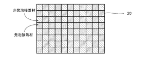
- FIG. 10 is an explanatory diagram of an insulating sheet of a modified example.
- FIG. 10 is an explanatory diagram of an insulating sheet of a modified example.
- FIG. 11 is an enlarged view of slots in a modified stator.
- FIG. 12A is an explanatory diagram of an insulating sheet of a modified example.
- FIG. 12B is an explanatory diagram of an insulating sheet of a modified example.
- FIG. 12C is an explanatory diagram of an insulating sheet of a modified example.
- FIG. 1 is an explanatory diagram of a stator 10 of a motor (rotary electric machine) to which an insulating sheet according to an embodiment of the present invention is applied, viewed from the rotation axis direction.
- the stator 10 includes a stator core 11 in which a plurality of slots 12 are formed, windings 30 inserted into the slots 12, and an insulating sheet 20 (see FIG. 2) that electrically insulates between the stator core 11 and the windings 30. and
- the stator core 11 is constructed by laminating electromagnetic steel plates punched in an annular shape in the rotation axis direction.
- the stator core 11 is formed with an annular back yoke 13 and a plurality of teeth 14 protruding from the back yoke 13 toward the inner circumference.
- a gap formed between the teeth 14 constitutes the slot 12 , and the winding 30 (shown hatched in FIG. 1 ) is inserted inside the slot 12 .
- a rotor (not shown) is arranged on the inner peripheral side of the stator 10 .
- the rotor rotates due to the action of the permanent magnets provided on the rotor.
- stator core 11 shown in FIG. 1 shows an example in which 48 slots 12 are formed, the number of slots 12 is not limited to this.
- the motor of this embodiment is mounted, for example, on an electric vehicle and functions as an electric motor that drives the wheels.
- the motor also functions as a generator that generates (regenerates) power by receiving the driving force generated by the rotation of the wheels.
- the motor may be used as a driving device for devices other than automobiles, such as various electric devices or industrial machines.
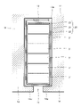
- FIG. 2 is a partially enlarged view of the slots 12 of the stator 10 of this embodiment.
- FIG. 2 will be described as a representative of one of the plurality of slots 12 in FIG. 1, but the configurations of the other slots 12 are the same.
- the slots 12 are gaps formed between the teeth 14 in the stator 10 .
- Protrusions 14a protruding in the circumferential direction are formed at the tips of the teeth 14, and the slots 12 are opened to the inner peripheral side of the stator 10 by the gaps 15 between the protrusions 14a.
- a winding 30 is inserted into the slot 12, and an insulating sheet 20 is interposed between the inner wall 12a of the slot 12 and the winding 30.
- the insulating sheet 20 electrically insulates between the stator core 11 and the windings 30 .
- the insulating sheet 20 has a foamable adhesive on its surface, which is foamed by heating, so that the inner wall 12a of the slot 12 and the winding 30 are tightly fixed.
- the winding 30 is composed of a plurality of rectangular wires 31 having an insulating coating.
- six rectangular wires 31 are accommodated in parallel in one slot 12 in the radial direction. Note that the number and shape of the windings 30 are not limited to this.
- the insulating sheet 20 placed between the slot 12 and the winding 30 is pre-applied with a thermosetting adhesive on both sides thereof.
- the wire 30 is inserted and heated to melt and harden the adhesive, so that the inner wall 12a of the slot 12 and the wire 30 are brought into close contact.
- the degree of adhesion on the surface is greater than that of the non-foaming adhesives.
- the insulating sheet 20 may stick and workability may deteriorate.
- the insulating sheet 20 is arranged around the winding 30 over the entire circumference of the inner wall 12a of the slot 12. As shown in FIG. At the radially outer bottom of the slot 12 , the insulating sheet 20 is overlapped at its starting and ending points.
- the insulating sheet 20 is composed of an insulating paper 21 , a first adhesive layer 22 provided on the surface of the insulating paper 21 , and a second adhesive layer 23 provided on the back surface of the insulating paper 21 .
- the front surface of the insulating paper 21 is the surface of the insulating sheet 20 on the inner wall 12a side of the slot 12
- the back surface of the insulating paper 21 is the surface of the insulating sheet 20 on the winding 30 side.
- the insulating paper 21 is formed into a sheet from an insulating material such as paper, nonwoven fabric, or resin.
- the first adhesive layer 22 is coated with a predetermined thickness of a foaming adhesive that hardens after being foamed by heating to expand its volume.
- a non-foaming adhesive that hardens without foaming when heated is applied to the second adhesive layer 23 in a predetermined thickness.
- Foaming adhesives are dispersed and mixed in the adhesive, for example, with fine binders that foam when heated. It is configured. The foamed adhesive hardens while maintaining its thickness by further heating.
- a non-foaming adhesive does not contain any foaming material. Non-foaming adhesives are melted by heating and hardened with little change in volume (thickness). The non-foaming adhesive is configured to have a lower surface tackiness than the foaming adhesive in an unheated state.
- the curing temperature of the non-foaming adhesive is set to be higher than the curing temperature of the foaming adhesive.
- the foam adhesive is made of, for example, urethane resin.
- the non-foaming adhesive is composed of epoxy resin, for example.
- FIG. 3 is a flow chart showing a method of assembling the stator 10 using the insulating sheet 20 of this embodiment.
- step S10 the insulating sheets 20 are attached in all the slots 12 of the stator core 11 respectively.
- a jig or the like is used to bring the first surface of the insulating sheet 20 into close contact with the inner wall 12a of the slot 12 .
- the surface of the insulating paper 21 is the first adhesive layer 22 that is coated with a highly sticky foamed adhesive on the entire surface, so that the insulating sheet 20 can be easily adhered to the inner wall 12a of the slot 12.
- the second adhesive layer 23 on the back surface of the insulating paper 21 is coated with a non-foaming adhesive having low adhesiveness, the non-foaming adhesive does not stick to the operator's hands or jigs during work. It does not interfere with work.
- step S20 the winding 30 is inserted into each slot 12.
- the winding 30 is composed of a plurality of rectangular wires 31 having a U-shape.
- a rectangular wire 31 is inserted in the axial direction of the slot 12 from the open end.
- the inner wall 12a of the slot 12 and the insulating sheet 20 are in close contact with each other with a highly adhesive foam adhesive.
- the insulating sheet 20 is less likely to shift when the winding 30 is inserted.
- step S30 the insulating sheet 20 attached inside the slot 12 is heated to the curing temperature.
- the insulating sheet 20 is kept at the curing temperature for a predetermined time until the foaming adhesive and the non-foaming adhesive fully cure. to maintain.
- step S30 the foaming adhesive is first melted due to the temperature rise.
- the foaming adhesive foams and increases in volume when melted. This increases the thickness of the foamed adhesive to fill the gap between the inner wall 12a of the slot 12 and the winding 30, as shown in FIG.
- the foam adhesive is then cured while maintaining this thickness. At the same time, or after curing of the foamed adhesive, the non-foamed adhesive melts and cures.
- the foaming adhesive disposed on the first adhesive layer 22 is foamed, thereby increasing the thickness of the first adhesive layer and creating a gap between the inner wall 12a of the slot 12 and the winding 30. embedded and the winding 30 is secured within the slot 12 .
- the stator 10 of the present embodiment includes the stator core 11 having the slots 12, the windings 30 inserted into the slots 12, and the windings 30 interposed between the slots 12 and the windings 30. and an insulating sheet 20 that electrically insulates the inner wall 12 a and the winding 30 .
- the insulating sheet 20 includes an insulating paper 21, a first adhesive layer 22 disposed on the surface of the insulating paper 21 facing the inner wall 12a of the slot 12, and a back surface of the insulating paper 21 facing the winding 30. and a second adhesive layer 23 .
- the first adhesive layer 22 includes a foaming adhesive that is thermally cured while foaming when heated, and the second adhesive layer 23 includes a non-foaming adhesive having a lower stickiness than the first adhesive when not heated. agent is placed.
- the foaming adhesive is arranged on the surface of the insulating sheet 20 facing the inner wall 12a of the slot 12, and the non-foaming adhesive with low adhesiveness is arranged on the back surface facing the winding 30 side. Therefore, when inserting the windings 30 into the slots 12, the insertion resistance of the windings 30 is reduced, and it is possible to suppress deterioration of workability due to displacement of the insulating sheet 20 and the like. Furthermore, after assembly, the foaming adhesive foams due to heating, which increases the thickness of the insulating sheet 20 and brings the windings 30 and the slots 12 into close contact with each other. can suppress the decrease in In addition, the clearance between the slot 12 and the winding 30 can be minimized, eliminating restrictions on the magnetic circuit design comprising the slot 12 and the winding 30. FIG. These can improve the motor efficiency.
- the insulating sheet 20 has a foaming adhesive on all of the first adhesive layer 22 and a non-foaming adhesive on all of the second adhesive layer 23 .
- the windings 30 can be brought into closer contact with the inner wall 12a of the slot 12 by the foamed adhesive.
- the curing temperature of the non-foaming adhesive is set to be equal to or higher than the curing temperature of the foaming adhesive.
- At least the foaming adhesive is placed on the surface of the insulating sheet 20 on the inner wall 12a side of the slot 12, and at least the non-foaming adhesive is placed on the surface of the insulating sheet 20 on the winding 30 side.
- the following modified example can be adopted.
- FIG. 5 is a partially enlarged view of the slot 12 of a modified example of this embodiment.
- the insulating sheet 20 has a first adhesive layer 22 and a second adhesive layer 23 on one of the two surfaces facing each other when placed in the slot 12. was placed. A non-foaming adhesive was placed on the first adhesive layer 22 and the second adhesive layer 23 on the other side.
- the foamed adhesive was placed on the entire left side in FIG. 5, and the foamed adhesive was placed on the opposite right side of the inner wall 12a in FIG. Further, the foaming adhesive is placed on the entire inner surface of the inner wall 12 a of the slot 12 near the gap 15 of the slot 12 , and the non-foaming adhesive is placed on the entire outer surface of the stator 10 on the far side in the radial direction. In the vicinity of the gap 15 of the slot 12, the start point and the end point of the insulating sheet 20 are overlapped.
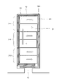
- FIG. 6 is a partially enlarged view of the slot 12 of another modified example of this embodiment.
- the winding 30 is composed of six rectangular wires 31 (31A, 31B, 31C, 31D, 31E, 31F) arranged in a row in the radial direction.
- the first adhesive layer 22 and the second adhesive layer 23 of the insulating sheet 20 facing one side surface (the left side in FIG. 6) of the slot 12 are foamed.
- a non-foaming adhesive is placed on the first adhesive layer 22 and the second adhesive layer 23 of the insulating sheet 20 facing the other side (the right side in FIG. 6).
- the arrangement of the foaming adhesive and the non-foaming adhesive is different from that of the one flat wire 31A. That is, in the other rectangular wire 31B, a non-foaming adhesive is arranged on the first adhesive layer 22 and the second adhesive layer 23 of the insulating sheet 20 facing one side (left side in FIG. 6), and the other A foaming adhesive is placed on the first adhesive layer 22 and the second adhesive layer 23 of the insulating sheet 20 facing the side surface (right side in FIG. 6).
- the foaming adhesive and the non-foaming adhesive of the first adhesive layer 22 and the second adhesive layer 23 of the insulating sheet 20 facing each other across the flat wire 31 are made different, and , the plurality of flat wires 31 adjacent in the radial direction are arranged so that the foaming adhesive and the non-foaming adhesive are alternately arranged in the radial direction. Also, regarding the radial direction of the slot 12, the foaming adhesive and the non-foaming adhesive of the first adhesive layer 22 and the second adhesive layer 23 of the insulating sheet 20 facing each other across the plurality of rectangular wires 31 arranged in a line are formed. were placed so as to differ from the agent.
- FIG. 7 is a partially enlarged view of the slot 12 of still another modified example of this embodiment.
- the modified example shown in FIG. 7 is similar to the modified example shown in FIG. 6, but a plurality of rectangular wires 31 are grouped together, and the first adhesive layer 22 and the second adhesive layer 22 of the insulating sheet 20 are attached to each group. Different adhesives were placed on the agent layer 23 .
- the insulating sheets 20 (both sides of the inner wall 12 a ) at positions facing the two flat wires 31 on the far side in the radial direction are a first group 311 .
- the insulating sheets 20 (both sides of the inner wall 12 a ) at positions facing the two rectangular wires 31 adjacent to the first group 311 are defined as a second group 312 .
- the insulating sheets 20 (both sides of the inner wall 12a) at positions facing the two radially outer rectangular wires 31 are defined as a third group 313 .
- the foamed adhesive is placed on the first adhesive layer 22 and the second adhesive layer 23 of the insulating sheet 20 facing one side (left side in FIG. 7), and the other side (left side in FIG. 7).
- a non-foaming adhesive is disposed on the first adhesive layer 22 and the second adhesive layer 23 of the insulating sheet 20 facing the right side of the 7).
- the foaming adhesive and the non-foaming adhesive are arranged differently. That is, in the second group 312, a non-foaming adhesive is placed on the first adhesive layer 22 and the second adhesive layer 23 of the insulating sheet 20 facing one side (the left side in FIG. 7), and the other side Foaming adhesive is disposed on the first adhesive layer 22 and the second adhesive layer 23 of the insulating sheet 20 facing (the right side in FIG. 7). Similarly, in the third group 313 adjacent to the second group 312, the arrangement of the foaming adhesive and the non-foaming adhesive is different from that of the second group 312. FIG.
- the foaming adhesive and the non-foaming adhesive of the first adhesive layer 22 and the second adhesive layer 23 of the insulating sheet 20 facing each other across the plurality of rectangular wires 31 arranged in a line are formed. were placed so as to differ from the agent.
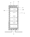
- FIG. 8 is a partially enlarged view of the slot 12 of still another modified example of this embodiment.
- the insulating sheet 20 is composed of a plurality of insulating sheets (first insulating sheet 20A, second insulating sheet 20B).
- a first insulating sheet 20A having a first adhesive layer 22 and a second adhesive layer 23 with a foam adhesive is inserted into one side surface of the slot 12 (left side in FIG. 8).
- a second insulating sheet 20B having a first adhesive layer 22 and a second adhesive layer 23 with a non-foaming adhesive is inserted into the other side surface of the slot 12 (right side in FIG. 8).
- the first insulating sheet 20A and the second insulating sheet 20B overlap each other at the bottom surface of the slot 12 on the far side in the radial direction and the gap 15 on the front side in the radial direction.
- a sheet 20B is arranged on the winding 30 side.
- the first insulating sheet 20A, on which only the foaming adhesive is placed, and the second insulating sheet 20B, on which only the non-foaming adhesive is placed are separately formed.
- the process for forming the first adhesive layer 22 and the second adhesive layer 23 in 20A and 20B is simplified, and the manufacturing cost of the insulating sheet 20 can be suppressed.
- the first insulating sheet 20A and the second insulating sheet 20B are overlapped at the bottom surface of the slot 12 on the far side in the radial direction and the gap 15 on the front side in the radial direction. It may be arranged so that it overlaps at another position.
- FIG. 9 is a partially enlarged view of the slot 12 of still another modification of the present embodiment
- FIG. 10 is an explanatory view of the insulation sheet 20 before and after heating.
- the thickness of the portion of the insulating sheet 20 to which the foaming adhesive is applied is smaller than the thickness of the portion to which the non-foaming adhesive is applied when not heated, and is heated to the curing temperature. Configured to grow later.
- the thickness of the insulating sheet 20 where the foaming adhesive is applied is smaller than the thickness of the non-foaming adhesive.
- the winding 30 is pressed at the location where the foamed adhesive is arranged, and the inner wall 12a of the slot 12 and the winding 30 are securely connected via the insulating sheet 20. can be fixed.
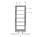
- FIG. 11 is a partially enlarged view of the slot 12 of still another modified example of this embodiment.
- the positions of the foaming adhesive and the non-foaming adhesive to be placed on the insulating sheet 20 are not related to the positions of the rectangular wire 31 of the winding 30 ( placed randomly).
- the thickness of the portion of the insulating sheet 20 to which the foaming adhesive is applied is smaller than the thickness of the portion to which the non-foaming adhesive is applied when not heated, and after heating to the curing temperature. configured to be large.
- the adhesive placed on the first adhesive layer 22 and the adhesive placed on the second adhesive layer 23 of the insulating sheet 20 at corresponding positions on the front and back sides are made different. That is, at certain locations of the insulating sheet 20, the foaming adhesive is placed on the first adhesive layer 22, and the non-foaming adhesive is placed on the second adhesive layer 23 on the back side. At another location, the first adhesive layer 22 has a non-foaming adhesive and the second adhesive layer 23 behind it has a foaming adhesive.
- 12A, 12B, and 12C are explanatory diagrams showing an example of the arrangement of the foaming adhesive and the non-foaming adhesive of the insulating sheet 20 in the modified example shown in FIG.
- FIGS. 12A, 12B, and 12C show the first adhesive layer 22 arranged on the surface of the insulating sheet 20.
- FIG. 12A shows an example in which a foaming adhesive and a non-foaming adhesive are alternately arranged in strips.
- FIG. 12B shows an example in which a circular foaming adhesive is dispersed in a non-foaming adhesive.
- FIG. 12C shows an example in which the foaming adhesive and the non-foaming adhesive are alternately arranged in a grid pattern.
- the thickness of the portion of the insulating sheet 20 to which the foaming adhesive is applied is set smaller than the thickness of the portion to which the non-foaming adhesive is applied.
- the degree of freedom in forming the first adhesive layer 22 and the second adhesive layer 23 on the insulating sheet 20 increases, and the insulating sheet 20 manufacturing cost can be reduced.
Landscapes
- Engineering & Computer Science (AREA)
- Power Engineering (AREA)
- Manufacturing & Machinery (AREA)
- Insulation, Fastening Of Motor, Generator Windings (AREA)
Priority Applications (5)
| Application Number | Priority Date | Filing Date | Title |
|---|---|---|---|
| US18/284,259 US20240154485A1 (en) | 2021-04-02 | 2021-04-02 | Stator |
| JP2023510157A JP7537603B2 (ja) | 2021-04-02 | 2021-04-02 | ステータ |
| PCT/JP2021/014400 WO2022208892A1 (ja) | 2021-04-02 | 2021-04-02 | ステータ |
| CN202180096195.2A CN117044076A (zh) | 2021-04-02 | 2021-04-02 | 定子 |
| EP21933498.4A EP4318891A4 (de) | 2021-04-02 | 2021-04-02 | Stator |
Applications Claiming Priority (1)
| Application Number | Priority Date | Filing Date | Title |
|---|---|---|---|
| PCT/JP2021/014400 WO2022208892A1 (ja) | 2021-04-02 | 2021-04-02 | ステータ |
Publications (1)
| Publication Number | Publication Date |
|---|---|
| WO2022208892A1 true WO2022208892A1 (ja) | 2022-10-06 |
Family
ID=83457567
Family Applications (1)
| Application Number | Title | Priority Date | Filing Date |
|---|---|---|---|
| PCT/JP2021/014400 WO2022208892A1 (ja) | 2021-04-02 | 2021-04-02 | ステータ |
Country Status (5)
| Country | Link |
|---|---|
| US (1) | US20240154485A1 (de) |
| EP (1) | EP4318891A4 (de) |
| JP (1) | JP7537603B2 (de) |
| CN (1) | CN117044076A (de) |
| WO (1) | WO2022208892A1 (de) |
Cited By (2)
| Publication number | Priority date | Publication date | Assignee | Title |
|---|---|---|---|---|
| WO2024095555A1 (ja) * | 2022-10-31 | 2024-05-10 | 株式会社日立製作所 | 回転電機および産業機械 |
| EP4391319A1 (de) * | 2022-12-22 | 2024-06-26 | Valeo eAutomotive Germany GmbH | Verfahren zur herstellung eines stators für eine elektrische rotierende maschine, stator, elektrische rotierende maschine und fahrzeug |
Citations (8)
| Publication number | Priority date | Publication date | Assignee | Title |
|---|---|---|---|---|
| JP2006094622A (ja) * | 2004-09-22 | 2006-04-06 | Toshiba Corp | 回転電機の固定子コイルの固定方法 |
| JP2011244596A (ja) | 2010-05-18 | 2011-12-01 | Toyota Motor Corp | 電動機のステータの製造方法 |
| JP2013009499A (ja) * | 2011-06-24 | 2013-01-10 | Toyota Motor Corp | 回転電機用絶縁部材、回転電機用ステータ、および、回転電機用ステータの製造方法 |
| WO2018131703A1 (ja) * | 2017-01-16 | 2018-07-19 | 本田技研工業株式会社 | 絶縁部材、回転電機のステータおよび回転電機 |
| JP2019022276A (ja) * | 2017-07-13 | 2019-02-07 | 株式会社デンソー | 回転電機の固定子、及びその固定子の製造方法 |
| JP2019161695A (ja) * | 2018-03-07 | 2019-09-19 | 本田技研工業株式会社 | 回転電機 |
| JP2020092482A (ja) * | 2018-12-03 | 2020-06-11 | トヨタ自動車株式会社 | ステータ |
| JP2020167797A (ja) * | 2019-03-28 | 2020-10-08 | アイシン・エィ・ダブリュ株式会社 | ステータの製造方法およびステータ |
Family Cites Families (3)
| Publication number | Priority date | Publication date | Assignee | Title |
|---|---|---|---|---|
| JP6685878B2 (ja) * | 2016-10-14 | 2020-04-22 | 本田技研工業株式会社 | 回転電機および回転電機の製造方法 |
| JP2018078764A (ja) * | 2016-11-11 | 2018-05-17 | トヨタ自動車株式会社 | モータ用ステータ |
| JP2019161951A (ja) * | 2018-03-15 | 2019-09-19 | 本田技研工業株式会社 | 回転電機のステータ |
-
2021
- 2021-04-02 JP JP2023510157A patent/JP7537603B2/ja active Active
- 2021-04-02 WO PCT/JP2021/014400 patent/WO2022208892A1/ja active Application Filing
- 2021-04-02 EP EP21933498.4A patent/EP4318891A4/de active Pending
- 2021-04-02 CN CN202180096195.2A patent/CN117044076A/zh active Pending
- 2021-04-02 US US18/284,259 patent/US20240154485A1/en active Pending
Patent Citations (8)
| Publication number | Priority date | Publication date | Assignee | Title |
|---|---|---|---|---|
| JP2006094622A (ja) * | 2004-09-22 | 2006-04-06 | Toshiba Corp | 回転電機の固定子コイルの固定方法 |
| JP2011244596A (ja) | 2010-05-18 | 2011-12-01 | Toyota Motor Corp | 電動機のステータの製造方法 |
| JP2013009499A (ja) * | 2011-06-24 | 2013-01-10 | Toyota Motor Corp | 回転電機用絶縁部材、回転電機用ステータ、および、回転電機用ステータの製造方法 |
| WO2018131703A1 (ja) * | 2017-01-16 | 2018-07-19 | 本田技研工業株式会社 | 絶縁部材、回転電機のステータおよび回転電機 |
| JP2019022276A (ja) * | 2017-07-13 | 2019-02-07 | 株式会社デンソー | 回転電機の固定子、及びその固定子の製造方法 |
| JP2019161695A (ja) * | 2018-03-07 | 2019-09-19 | 本田技研工業株式会社 | 回転電機 |
| JP2020092482A (ja) * | 2018-12-03 | 2020-06-11 | トヨタ自動車株式会社 | ステータ |
| JP2020167797A (ja) * | 2019-03-28 | 2020-10-08 | アイシン・エィ・ダブリュ株式会社 | ステータの製造方法およびステータ |
Non-Patent Citations (1)
| Title |
|---|
| See also references of EP4318891A4 |
Cited By (2)
| Publication number | Priority date | Publication date | Assignee | Title |
|---|---|---|---|---|
| WO2024095555A1 (ja) * | 2022-10-31 | 2024-05-10 | 株式会社日立製作所 | 回転電機および産業機械 |
| EP4391319A1 (de) * | 2022-12-22 | 2024-06-26 | Valeo eAutomotive Germany GmbH | Verfahren zur herstellung eines stators für eine elektrische rotierende maschine, stator, elektrische rotierende maschine und fahrzeug |
Also Published As
| Publication number | Publication date |
|---|---|
| JP7537603B2 (ja) | 2024-08-21 |
| EP4318891A4 (de) | 2024-05-15 |
| EP4318891A1 (de) | 2024-02-07 |
| US20240154485A1 (en) | 2024-05-09 |
| CN117044076A (zh) | 2023-11-10 |
| JPWO2022208892A1 (de) | 2022-10-06 |
Similar Documents
| Publication | Publication Date | Title |
|---|---|---|
| JP5833844B2 (ja) | 回転電機用絶縁部材、回転電機用ステータ、および、回転電機用ステータの製造方法 | |
| WO2022208892A1 (ja) | ステータ | |
| JP5718854B2 (ja) | 回転電機用膨張シート、回転電機用膨張シートを用いた回転電機用ステータおよび回転電機用ステータの製造方法 | |
| JP4661261B2 (ja) | 回転電機の回転子構造 | |
| JP6959778B2 (ja) | 回転電機の固定子、及びその固定子の製造方法 | |
| JP6307876B2 (ja) | ステータ、及び、ステータの製造方法 | |
| JP2006311782A (ja) | ロータおよびその製造方法 | |
| JP6350107B2 (ja) | ステータのインシュレータ及びこれを用いた回転電機用ステータ、並びに、回転電機用ステータの製造方法 | |
| JP7047897B2 (ja) | 電機子の製造方法及び電機子 | |
| CN111446790A (zh) | 转子 | |
| JP2019161695A (ja) | 回転電機 | |
| JP2011205834A (ja) | ステータの製造方法 | |
| JP6680199B2 (ja) | 回転電機のステータの製造方法 | |
| JP5742414B2 (ja) | ステータの製造方法 | |
| JP2019115170A (ja) | ステータおよびステータの製造方法 | |
| JP2015133810A (ja) | 回転電機の固定子 | |
| JP7365949B2 (ja) | 絶縁シート、ステータの製造方法及びステータ | |
| JP5991011B2 (ja) | モータの固定子構造及びその製作方法 | |
| JP6939609B2 (ja) | 電機子の製造方法及び電機子 | |
| WO2020067352A1 (ja) | ステータの製造方法 | |
| WO2020067353A1 (ja) | ステータの製造方法 | |
| JP4504143B2 (ja) | 回転電機の固定子コイルの固定方法 | |
| JP2020141536A (ja) | ステータ | |
| JP2006158070A (ja) | 回転電機 | |
| JP7239284B2 (ja) | 回転電機のステータ |
Legal Events
| Date | Code | Title | Description |
|---|---|---|---|
| 121 | Ep: the epo has been informed by wipo that ep was designated in this application |
Ref document number: 21933498 Country of ref document: EP Kind code of ref document: A1 |
|
| WWE | Wipo information: entry into national phase |
Ref document number: 202180096195.2 Country of ref document: CN Ref document number: 2023510157 Country of ref document: JP |
|
| WWE | Wipo information: entry into national phase |
Ref document number: 18284259 Country of ref document: US |
|
| WWE | Wipo information: entry into national phase |
Ref document number: 2021933498 Country of ref document: EP |
|
| ENP | Entry into the national phase |
Ref document number: 2021933498 Country of ref document: EP Effective date: 20231102 |
|
| NENP | Non-entry into the national phase |
Ref country code: DE |