WO2022208705A1 - Élément de batterie à combustible et son procédé de fabrication - Google Patents
Élément de batterie à combustible et son procédé de fabrication Download PDFInfo
- Publication number
- WO2022208705A1 WO2022208705A1 PCT/JP2021/013769 JP2021013769W WO2022208705A1 WO 2022208705 A1 WO2022208705 A1 WO 2022208705A1 JP 2021013769 W JP2021013769 W JP 2021013769W WO 2022208705 A1 WO2022208705 A1 WO 2022208705A1
- Authority
- WO
- WIPO (PCT)
- Prior art keywords
- solid electrolyte
- electrolyte layer
- layer
- electrode layer
- fuel cell
- Prior art date
Links
- 239000000446 fuel Substances 0.000 title claims abstract description 142
- 238000004519 manufacturing process Methods 0.000 title claims description 28
- 239000007784 solid electrolyte Substances 0.000 claims abstract description 273
- 239000000758 substrate Substances 0.000 claims abstract description 142
- 238000000034 method Methods 0.000 claims description 66
- 229910052751 metal Inorganic materials 0.000 claims description 35
- 239000002184 metal Substances 0.000 claims description 35
- 239000000463 material Substances 0.000 claims description 18
- 229910044991 metal oxide Inorganic materials 0.000 claims description 10
- 150000004706 metal oxides Chemical class 0.000 claims description 10
- PNEYBMLMFCGWSK-UHFFFAOYSA-N aluminium oxide Inorganic materials [O-2].[O-2].[O-2].[Al+3].[Al+3] PNEYBMLMFCGWSK-UHFFFAOYSA-N 0.000 claims description 7
- 239000010408 film Substances 0.000 abstract description 51
- 239000000126 substance Substances 0.000 abstract description 12
- 239000010409 thin film Substances 0.000 abstract description 10
- 230000007423 decrease Effects 0.000 abstract description 4
- 239000012528 membrane Substances 0.000 abstract description 4
- 210000004027 cell Anatomy 0.000 description 127
- BASFCYQUMIYNBI-UHFFFAOYSA-N platinum Chemical compound [Pt] BASFCYQUMIYNBI-UHFFFAOYSA-N 0.000 description 26
- 239000007789 gas Substances 0.000 description 24
- 238000010586 diagram Methods 0.000 description 19
- 230000008569 process Effects 0.000 description 19
- 239000002737 fuel gas Substances 0.000 description 18
- XUIMIQQOPSSXEZ-UHFFFAOYSA-N Silicon Chemical compound [Si] XUIMIQQOPSSXEZ-UHFFFAOYSA-N 0.000 description 17
- 229910052710 silicon Inorganic materials 0.000 description 17
- 239000010703 silicon Substances 0.000 description 17
- CMIHHWBVHJVIGI-UHFFFAOYSA-N gadolinium(iii) oxide Chemical compound [O-2].[O-2].[O-2].[Gd+3].[Gd+3] CMIHHWBVHJVIGI-UHFFFAOYSA-N 0.000 description 16
- PXHVJJICTQNCMI-UHFFFAOYSA-N Nickel Chemical compound [Ni] PXHVJJICTQNCMI-UHFFFAOYSA-N 0.000 description 14
- 230000001590 oxidative effect Effects 0.000 description 13
- 229910052697 platinum Inorganic materials 0.000 description 13
- 230000004048 modification Effects 0.000 description 10
- 238000012986 modification Methods 0.000 description 10
- 239000011195 cermet Substances 0.000 description 8
- 238000004544 sputter deposition Methods 0.000 description 8
- 229910001233 yttria-stabilized zirconia Inorganic materials 0.000 description 8
- RUDFQVOCFDJEEF-UHFFFAOYSA-N yttrium(III) oxide Inorganic materials [O-2].[O-2].[O-2].[Y+3].[Y+3] RUDFQVOCFDJEEF-UHFFFAOYSA-N 0.000 description 8
- 230000002950 deficient Effects 0.000 description 7
- 229910052759 nickel Inorganic materials 0.000 description 7
- 239000007800 oxidant agent Substances 0.000 description 7
- MCMNRKCIXSYSNV-UHFFFAOYSA-N Zirconium dioxide Chemical compound O=[Zr]=O MCMNRKCIXSYSNV-UHFFFAOYSA-N 0.000 description 6
- 230000015572 biosynthetic process Effects 0.000 description 6
- 238000005498 polishing Methods 0.000 description 6
- 238000005546 reactive sputtering Methods 0.000 description 5
- 238000000231 atomic layer deposition Methods 0.000 description 4
- CETPSERCERDGAM-UHFFFAOYSA-N ceric oxide Chemical compound O=[Ce]=O CETPSERCERDGAM-UHFFFAOYSA-N 0.000 description 4
- 229910000422 cerium(IV) oxide Inorganic materials 0.000 description 4
- 230000007547 defect Effects 0.000 description 4
- 230000000694 effects Effects 0.000 description 4
- 239000000203 mixture Substances 0.000 description 4
- 239000007787 solid Substances 0.000 description 4
- 238000007517 polishing process Methods 0.000 description 3
- 239000011148 porous material Substances 0.000 description 3
- 238000010248 power generation Methods 0.000 description 3
- UFHFLCQGNIYNRP-UHFFFAOYSA-N Hydrogen Chemical compound [H][H] UFHFLCQGNIYNRP-UHFFFAOYSA-N 0.000 description 2
- 210000000170 cell membrane Anatomy 0.000 description 2
- 238000009826 distribution Methods 0.000 description 2
- 238000010304 firing Methods 0.000 description 2
- 239000001257 hydrogen Substances 0.000 description 2
- 229910052739 hydrogen Inorganic materials 0.000 description 2
- 239000012212 insulator Substances 0.000 description 2
- 150000002500 ions Chemical class 0.000 description 2
- 230000000149 penetrating effect Effects 0.000 description 2
- 230000010287 polarization Effects 0.000 description 2
- 238000000427 thin-film deposition Methods 0.000 description 2
- MYMOFIZGZYHOMD-UHFFFAOYSA-N Dioxygen Chemical compound O=O MYMOFIZGZYHOMD-UHFFFAOYSA-N 0.000 description 1
- 230000008901 benefit Effects 0.000 description 1
- 230000000903 blocking effect Effects 0.000 description 1
- 229910001882 dioxygen Inorganic materials 0.000 description 1
- 230000005611 electricity Effects 0.000 description 1
- 239000007772 electrode material Substances 0.000 description 1
- 239000003792 electrolyte Substances 0.000 description 1
- 238000005516 engineering process Methods 0.000 description 1
- 238000005530 etching Methods 0.000 description 1
- 230000012447 hatching Effects 0.000 description 1
- 230000006872 improvement Effects 0.000 description 1
- 230000003647 oxidation Effects 0.000 description 1
- 238000007254 oxidation reaction Methods 0.000 description 1
- 229910001220 stainless steel Inorganic materials 0.000 description 1
Images


Classifications
-
- H—ELECTRICITY
- H01—ELECTRIC ELEMENTS
- H01M—PROCESSES OR MEANS, e.g. BATTERIES, FOR THE DIRECT CONVERSION OF CHEMICAL ENERGY INTO ELECTRICAL ENERGY
- H01M8/00—Fuel cells; Manufacture thereof
- H01M8/10—Fuel cells with solid electrolytes
- H01M8/12—Fuel cells with solid electrolytes operating at high temperature, e.g. with stabilised ZrO2 electrolyte
- H01M8/1213—Fuel cells with solid electrolytes operating at high temperature, e.g. with stabilised ZrO2 electrolyte characterised by the electrode/electrolyte combination or the supporting material
-
- H—ELECTRICITY
- H01—ELECTRIC ELEMENTS
- H01M—PROCESSES OR MEANS, e.g. BATTERIES, FOR THE DIRECT CONVERSION OF CHEMICAL ENERGY INTO ELECTRICAL ENERGY
- H01M8/00—Fuel cells; Manufacture thereof
- H01M8/10—Fuel cells with solid electrolytes
- H01M8/12—Fuel cells with solid electrolytes operating at high temperature, e.g. with stabilised ZrO2 electrolyte
- H01M8/1213—Fuel cells with solid electrolytes operating at high temperature, e.g. with stabilised ZrO2 electrolyte characterised by the electrode/electrolyte combination or the supporting material
- H01M8/1226—Fuel cells with solid electrolytes operating at high temperature, e.g. with stabilised ZrO2 electrolyte characterised by the electrode/electrolyte combination or the supporting material characterised by the supporting layer
-
- H—ELECTRICITY
- H01—ELECTRIC ELEMENTS
- H01M—PROCESSES OR MEANS, e.g. BATTERIES, FOR THE DIRECT CONVERSION OF CHEMICAL ENERGY INTO ELECTRICAL ENERGY
- H01M8/00—Fuel cells; Manufacture thereof
- H01M8/10—Fuel cells with solid electrolytes
- H01M8/12—Fuel cells with solid electrolytes operating at high temperature, e.g. with stabilised ZrO2 electrolyte
- H01M8/124—Fuel cells with solid electrolytes operating at high temperature, e.g. with stabilised ZrO2 electrolyte characterised by the process of manufacturing or by the material of the electrolyte
- H01M8/1246—Fuel cells with solid electrolytes operating at high temperature, e.g. with stabilised ZrO2 electrolyte characterised by the process of manufacturing or by the material of the electrolyte the electrolyte consisting of oxides
- H01M8/1253—Fuel cells with solid electrolytes operating at high temperature, e.g. with stabilised ZrO2 electrolyte characterised by the process of manufacturing or by the material of the electrolyte the electrolyte consisting of oxides the electrolyte containing zirconium oxide
-
- H—ELECTRICITY
- H01—ELECTRIC ELEMENTS
- H01M—PROCESSES OR MEANS, e.g. BATTERIES, FOR THE DIRECT CONVERSION OF CHEMICAL ENERGY INTO ELECTRICAL ENERGY
- H01M8/00—Fuel cells; Manufacture thereof
- H01M8/10—Fuel cells with solid electrolytes
- H01M8/12—Fuel cells with solid electrolytes operating at high temperature, e.g. with stabilised ZrO2 electrolyte
- H01M8/1286—Fuel cells applied on a support, e.g. miniature fuel cells deposited on silica supports
-
- H—ELECTRICITY
- H01—ELECTRIC ELEMENTS
- H01M—PROCESSES OR MEANS, e.g. BATTERIES, FOR THE DIRECT CONVERSION OF CHEMICAL ENERGY INTO ELECTRICAL ENERGY
- H01M8/00—Fuel cells; Manufacture thereof
- H01M8/10—Fuel cells with solid electrolytes
- H01M8/12—Fuel cells with solid electrolytes operating at high temperature, e.g. with stabilised ZrO2 electrolyte
- H01M2008/1293—Fuel cells with solid oxide electrolytes
-
- Y—GENERAL TAGGING OF NEW TECHNOLOGICAL DEVELOPMENTS; GENERAL TAGGING OF CROSS-SECTIONAL TECHNOLOGIES SPANNING OVER SEVERAL SECTIONS OF THE IPC; TECHNICAL SUBJECTS COVERED BY FORMER USPC CROSS-REFERENCE ART COLLECTIONS [XRACs] AND DIGESTS
- Y02—TECHNOLOGIES OR APPLICATIONS FOR MITIGATION OR ADAPTATION AGAINST CLIMATE CHANGE
- Y02E—REDUCTION OF GREENHOUSE GAS [GHG] EMISSIONS, RELATED TO ENERGY GENERATION, TRANSMISSION OR DISTRIBUTION
- Y02E60/00—Enabling technologies; Technologies with a potential or indirect contribution to GHG emissions mitigation
- Y02E60/30—Hydrogen technology
- Y02E60/50—Fuel cells
-
- Y—GENERAL TAGGING OF NEW TECHNOLOGICAL DEVELOPMENTS; GENERAL TAGGING OF CROSS-SECTIONAL TECHNOLOGIES SPANNING OVER SEVERAL SECTIONS OF THE IPC; TECHNICAL SUBJECTS COVERED BY FORMER USPC CROSS-REFERENCE ART COLLECTIONS [XRACs] AND DIGESTS
- Y02—TECHNOLOGIES OR APPLICATIONS FOR MITIGATION OR ADAPTATION AGAINST CLIMATE CHANGE
- Y02P—CLIMATE CHANGE MITIGATION TECHNOLOGIES IN THE PRODUCTION OR PROCESSING OF GOODS
- Y02P70/00—Climate change mitigation technologies in the production process for final industrial or consumer products
- Y02P70/50—Manufacturing or production processes characterised by the final manufactured product
Definitions
- the present invention relates to a solid oxide fuel cell in which a solid electrolyte layer is formed by a film-forming process.
- Patent Document 1 JP-A-2016-115506
- Non-Patent Document 1 Journal of Power Sources 194 (2009) 119-129
- Non-Patent Document 1 describes a cell technology that forms the anode layer, solid electrolyte layer, and cathode layer of a fuel cell membrane by a thin film deposition process.
- the ionic conductivity can be improved and the power generation efficiency can be improved.
- the ionic conductivity of solid electrolytes exhibits an activated temperature dependence. Therefore, the ionic conductivity is large at high temperatures and small at low temperatures.
- a sufficiently large ion conductivity can be obtained even at low temperatures, and practical power generation efficiency can be realized.
- YSZ Yttria Stabilized Zirconia
- yttria or the like zirconia doped with yttria or the like
- porous electrodes By using porous electrodes as the anode layer and the cathode layer, it is possible to increase the three-phase interface where the gas, the electrode, and the solid electrolyte are in contact with each other, and it is possible to suppress the power loss due to the polarization resistance generated at the electrode interface. .
- the output power per area can be improved, but thinning causes a problem of leakage current in the solid electrolyte layer between the anode layer and the cathode.
- a uniform solid electrolyte layer can be formed, for example, when YSZ is used for the solid electrolyte layer, the thickness can be reduced to 100 nanometers or less.
- an extremely thin portion is formed in the solid electrolyte layer due to foreign matter present in the underlying layer before the solid electrolyte layer is formed, resulting in an increase in leakage current between the anode layer and the cathode.
- Non-Patent Document 2 discloses a technique for filling voids formed in the solid electrolyte layer, although it is not a countermeasure against foreign matter existing in the underlying layer before the solid electrolyte layer is formed. After filling the voids formed in the solid electrolyte layer (YSZ layer) formed on the anode layer by forming an alumina film by the atomic layer deposition method (ALD method), part of the alumina is removed by etching back. Subsequently, a solid electrolyte layer (YSZ layer) is additionally formed.
- ALD method atomic layer deposition method
- Non-Patent Document 1 With the method described in Non-Patent Document 1, the voids formed in the solid electrolyte can be filled, but the influence of foreign matter present in the underlying layer cannot be suppressed before the solid electrolyte layer is formed.
- the electrodes In a fuel cell, the electrodes must be porous because they are required to diffuse gas. Therefore, when forming the solid electrolyte layer, it is formed on a porous electrode. Since the porous electrode has a structure in which granular electrode materials are gathered, the frequency of foreign matter generated during formation is very high compared to a flat and dense electrode.
- the film thickness of the solid electrolyte layer is extremely thin at the foreign substance portion, and in extreme cases, solid Pores are formed in the electrolyte layer.
- the fuel gas supplied to the anode side and the oxidant gas supplied to the cathode side are mutually diffused through the holes of the solid electrolyte layer, and the output power of the fuel cell is also increased. lower the
- the present invention has been made in view of the above-described problems, and suppresses a decrease in output power due to foreign matter present in the underlying layer when the thin-film solid electrolyte layer is formed, and increases the area of the fuel cell.
- the object is to increase the yield and reduce the cost of the fuel cell.
- a membrane electrode assembly composed of a lower electrode layer, a first solid electrolyte layer, a second solid electrolyte layer, and an upper electrode layer is formed on a support substrate, and the first solid electrolyte layer and the second solid electrolyte layer are formed on the support substrate.
- the interface between the solid electrolyte layer is flat compared to the interface between the lower electrode layer and the solid electrolyte layer, and the second solid electrolyte layer is flat when the output voltage of the fuel cell is generated.
- the film thickness is such that the leakage current between the first solid electrolyte layer and the second solid electrolyte layer is less than the allowable value.
- the fuel cell according to the present invention it is possible to provide a solid oxide fuel cell that has a large output power per area, can have a large area, and can operate at a low temperature. Problems, configurations and effects other than those described above will be clarified by the following description of the embodiments.
- FIG. 1 is a diagram showing a general structure of a fuel cell with a thin-film solid electrolyte layer;
- FIG. 1 is a schematic diagram showing a configuration example of a fuel cell module using a thin film process SOFC according to Embodiment 1.
- FIG. It is the figure which looked at the shielding plate from the fuel cell side. It is the figure which looked at the fuel cell from the back side of a shielding plate.
- 1 is a schematic diagram showing a configuration example of a fuel cell 1 according to Embodiment 1.
- FIG. 6 is a diagram illustrating an example of a method of forming the fuel cell 1 shown in FIG. 5.
- FIG. 6 is a diagram illustrating an example of a method of forming the fuel cell 1 shown in FIG. 5.
- FIG. 6 is a diagram illustrating an example of a method of forming the fuel cell 1 shown in FIG. 5.
- FIG. 6 is a diagram illustrating an example of a method of forming the fuel cell 1 shown in FIG. 5.
- FIG. 6 is a diagram illustrating an example of a method of forming the fuel cell 1 shown in FIG. 5.
- FIG. 6 is a diagram illustrating an example of a method of forming the fuel cell 1 shown in FIG. 5.
- FIG. 6 is a diagram illustrating an example of a method of forming the fuel cell 1 shown in FIG. 5.
- FIG. 2 shows the difference in shape between the fuel cell of the prior art and the fuel cell 1 according to the first embodiment at the portion where the foreign matter 200 exists on the lower electrode layer 20.
- FIG. FIG. 2 shows the difference in shape between the fuel cell of the prior art and the fuel cell 1 according to the first embodiment at the portion where the foreign matter 200 exists on the lower electrode layer 20.
- FIG. 3 is a diagram for explaining leakage current of the fuel cell 1 according to Embodiment 1;
- a manufacturing method of a modified example using the first porous metal substrate 71 as the substrate of the fuel cell 1 is shown.
- a manufacturing method of a modified example using the first porous metal substrate 71 as the substrate of the fuel cell 1 is shown.
- a manufacturing method of a modified example using the first porous metal substrate 71 as the substrate of the fuel cell 1 is shown.
- a manufacturing method of a modified example using the first porous metal substrate 71 as the substrate of the fuel cell 1 is shown.
- a manufacturing method of a modified example using the first porous metal substrate 71 as the substrate of the fuel cell 1 is shown.
- 1 shows an example of a method for manufacturing the fuel cell 1 in Embodiment 2.
- FIG. 1 shows an example of a method for manufacturing the fuel cell 1 in Embodiment 2.
- FIG. 1 shows an example of a method for manufacturing the fuel cell 1 in Embodiment 2.
- FIG. 1 shows an example of a method for manufacturing the fuel cell 1 in Embodiment 2.
- FIG. 1 shows an example of a method for manufacturing the fuel cell 1 in Embodiment 2.
- FIG. 1 shows an example of a method for manufacturing the fuel cell 1 in Embodiment 2.
- FIG. 1 shows an example of a method for manufacturing the fuel cell 1 in Embodiment 2.
- FIG. The shape of the fuel cell 1 according to Embodiment 2 is shown at the portions where the foreign matter 200 exists on the lower electrode layer 20 and the upper electrode layer 10 . 4 shows a modification of Embodiment 2.
- FIG. 1 shows an example of a method for manufacturing the fuel cell 1 in Embodiment 2.
- FIG. 1 shows an example of a method for manufacturing the fuel cell 1 in Embodiment 2.
- FIG. 1 shows an example of
- the X direction, Y direction, and Z direction are used as directions for explanation.
- the X direction and the Y direction are orthogonal to each other and constitute a horizontal plane, and the Z direction is a direction perpendicular to the horizontal plane.
- hatching may be omitted even in cross-sectional views to make the drawings easier to see. Also, even a plan view may be hatched to make the drawing easier to see.
- each part does not correspond to the actual device, and in order to make the drawing easier to understand, certain parts may be shown relatively large. Also, even when the cross-sectional view and the plan view correspond to each other, there are cases where a specific portion is displayed relatively large in order to make the drawing easier to understand.
- FIG. 1 is a diagram showing a general structure of a fuel cell having a thin-film solid electrolyte layer.
- the solid electrolyte layer that constitutes the membrane electrode assembly for fuel cells.
- Fuel cells are the best. If the anode electrode layer, the solid electrolyte layer, and the cathode electrode layer are all made thin, the mechanical strength of the fuel cell membrane electrode assembly is weakened, but this can be compensated for by supporting the substrate as shown in FIG.
- the substrate for example, an anodized alumina substrate (AAO substrate) 4 can be used as shown in FIG. In FIG.
- a first solid electrolyte layer 101 is formed on a lower electrode layer 20 formed on a first AAO substrate 4, and an upper electrode layer 10 is formed thereon.
- the first AAO substrate 4 can supply fuel gas or oxidant gas from the back surface to the lower electrode layer 20 through the first holes 51 .
- the upper electrode layer 10 and the lower electrode layer 20 can be made porous.
- FIG. 2 is a schematic diagram showing a configuration example of a fuel cell module using a thin film process SOFC (Solid Oxide Fuel Cell) according to Embodiment 1 of the present invention.
- the gas flow path in the module is separated into a flow path for fuel gas and a flow path for gas containing oxygen gas (for example, air; the same applies hereinafter).
- the fuel gas flow path includes a fuel inlet, a fuel chamber, and a fuel outlet.
- the air flow path includes an air inlet, an air chamber, and an air outlet.
- Fuel gas and air are shielded by the shield plate in FIG. 2 so as not to mix inside the module. Wires are led out from the anode and cathode electrodes of the fuel cell by connectors and connected to an external load.
- FIG. 3 is a diagram of the shielding plate viewed from the fuel cell side.
- the fuel cell is mounted on the shield plate. Although one fuel cell may be used, generally a plurality of cells are arranged.
- Fig. 4 is a view of the fuel cell seen from the back side of the shield plate. A hole is formed in the shield plate for each fuel cell so that the fuel gas is supplied from the fuel chamber to the fuel cell.
- FIG. 5 is a schematic diagram showing a configuration example of the fuel cell 1 according to the first embodiment.
- the fuel cell 1 corresponds to the fuel cells shown in FIGS.
- a lower electrode layer 20 is formed on the first AAO substrate 4 .
- a first hole 51 is formed in the first AAO substrate 4, and a fuel gas or an oxidant gas can be supplied to the lower electrode layer 20 from the back surface through the hole.
- the lower electrode layer 20 can be formed of, for example, platinum, a cermet material composed of platinum and a metal oxide, nickel, a cermet material composed of nickel and a metal oxide, or the like. Power can be supplied to the lower electrode layer 20 from the rear surface of the first AAO substrate 4 via the lower electrode wiring layer 21 formed on the side walls of the first holes 51 .
- the lower electrode wiring layer 21 can be made of platinum, nickel, or the like, for example.
- the lower electrode layer 20 and the lower electrode wiring layer 21 can be made of a porous material.
- An yttria-doped zirconia thin film serving as the first solid electrolyte layer 101 is formed on the upper layer of the lower electrode layer 20 .
- the yttria doping amount can be, for example, 3% or 8%.
- the first solid electrolyte layer 101 is formed to completely cover the lower electrode layer 20 on the first AAO substrate.
- the film thickness of the first solid electrolyte layer 101 can be equal to or greater than the unevenness (D) of the predetermined region of the surface of the underlying lower electrode layer 20, and can be equal to or less than twice (2 ⁇ D). For example, when D is 100 nm, it should be 100 nm or more and 200 nm or less.
- first solid electrolyte layer 101 can be flattened compared to the surface of lower electrode layer 20 . As will be described later, this can be achieved by using a chemical mechanical polishing method (CMP method) after forming the first solid electrolyte layer 101 .
- CMP method chemical mechanical polishing method
- the unevenness (D) referred to here can be defined, for example, as the sum of the maximum peak height and the maximum valley depth within a predetermined region on the surface.
- An yttria-doped zirconia thin film serving as the second solid electrolyte layer 102 is formed on the upper layer of the first solid electrolyte layer 101 .
- the yttria doping amount can be, for example, 3% or 8%.
- the material of the second solid electrolyte layer 102 the same material as that of the first solid electrolyte layer can be used.
- Second solid electrolyte layer 102 is formed to completely cover first solid electrolyte layer 101 .
- the film thickness of the second solid electrolyte layer 102 is such that the second solid electrolyte layer 102 alone can sufficiently suppress current due to electron leak and hole leak between the anode layer and the cathode layer.
- the thickness of the second solid electrolyte layer 102 is reduced to 100 nm or less.
- the total film thickness of the first solid electrolyte layer and the second solid electrolyte layer can be made 1000 nm or less.
- a first interface layer 61 is formed on the upper layer of the second solid electrolyte layer 102 .
- the first interface layer 61 can be made of ceria (CeO2) doped with 10% gadolinia (Gd2O3), for example.
- First interface layer 61 is formed to cover the upper surface of second solid electrolyte layer 102 .
- the second solid electrolyte layer 102 and the upper electrode layer 10 are likely to chemically react due to the manufacturing process of the fuel cell 1 or the heat load during operation, it is not preferable to bring them into direct contact with each other. 61 is used.
- the first interface layer 61 By forming the first interface layer 61 between the upper electrode layer 10 and the second solid electrolyte layer 102, the effect of reducing the polarization resistance in the upper electrode layer 10 during operation may be obtained. Depending on the usage conditions such as the operating temperature of the fuel cell 1, the first interface layer 61 may not be formed. Further, as will be described later, it is also possible to separately form an interface layer at the interface between the lower electrode layer 20 and the first solid electrolyte layer 101 .
- the upper electrode layer 10 is formed on the upper layer of the first interface layer 61 .
- the upper electrode layer 10 can be made of, for example, porous platinum or a cermet material composed of platinum and a metal oxide.
- the upper electrode layer 10 is formed so as to partially cover the first AAO substrate 4 .
- the thin film process type fuel cell 1 includes, from the bottom layer, the first AAO substrate 4, the bottom electrode wiring layer 21, the bottom electrode layer 20, the first solid electrolyte layer 101, the second solid electrolyte layer 102, the first interface It comprises a membrane electrode assembly composed of a layer 61 and an upper electrode layer 10 .
- a fuel gas containing hydrogen is supplied to the lower electrode layer 20 side, and an oxidizing gas such as air is supplied to the upper electrode layer 10 side.
- the supplied fuel gas reaches the lower electrode layer 20 through the first holes 51 of the first AAO substrate 4 .
- the supplied oxidizing gas is supplied to the surface of the upper electrode layer 10 .
- the oxidation gas and the fuel gas react with each other through ion conduction through the first solid electrolyte layer 101, the second solid electrolyte layer 102, and the first interface layer 61, so that the fuel cell can operate in the same manner as a normal fuel cell.
- the space between the lower electrode layer 20 side and the upper electrode layer 10 side is sealed so that the oxidizing gas and the fuel gas to be supplied do not mix with each other in the gaseous state.
- the fuel gas and the oxidizing gas can be supplied by supplying an oxidizing gas such as air to the lower electrode layer 20 side and supplying a fuel gas containing hydrogen to the upper electrode layer 10 side. Also in this case, the space between the lower electrode layer 20 side and the upper electrode layer 10 side is sealed so that the supplied oxidizing gas and fuel gas do not mix with each other in the gas state.
- FIG. 1 a first AAO substrate 4 is formed on a silicon substrate 2 (FIG. 6).
- the first AAO substrate 4 is formed with a plurality of first holes 51 penetrating between the front and back surfaces.
- the diameter of the first holes 51 can be, for example, 50-100 nm.
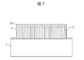
- a lower electrode layer 20 is formed on the first AAO substrate 4 (FIG. 7).
- the lower electrode layer 20 is formed by sputtering using a cermet made of nickel and YSZ, and the film thickness can be set to 100 to 200 nm. Since the upper surface of the first AAO substrate 4 is uneven and the lower electrode layer 20 is porous, the upper surface of the lower electrode layer 20 is uneven. In addition, the frequency of foreign matter generated and adhering to the surface of the lower electrode layer 20 during the formation of the porous lower electrode layer 20 is extremely high.
- the foreign matter generated in the film forming process of the lower electrode layer 20 is conductive, and as described later, in the conventional fuel cell, it causes electron leakage and hole leakage between the anode layer and the cathode layer, and the output of the fuel cell is reduced. Since it lowers the voltage, countermeasures are essential.
- the lower electrode layer 20 is formed not only on the upper surface of the first AAO substrate 4 but also on the side surfaces of the first AAO substrate 4 and the upper surface of the silicon substrate 2 as shown in FIG.
- the silicon substrate 2 can be replaced by substrates using other materials as long as they have sufficient strength, flatness of the surface, and ease of processing.
- a first solid electrolyte layer 101 is formed on the upper surface of the lower electrode layer 20 (FIG. 8).
- the material of the first solid electrolyte layer 101 can be doped with 3% or 8% yttria, for example.
- the solid electrolyte layer has a function of preventing mixing of gases on the anode side and the cathode side, so it is formed densely.
- the dense first solid electrolyte layer 101 can be formed by a sputtering method using an oxide target or a reactive sputtering method using a metal target. Since the upper surface of lower electrode layer 20 is uneven, the upper surface of first solid electrolyte layer 101 is uneven.
- the first solid electrolyte layer 101 does not have a desired film thickness at the foreign substance portion.
- the shape of the foreign matter portion will be described later (FIG. 13).
- the first solid electrolyte layer 101 is formed not only on the upper surface of the first AAO substrate 4 but also on the side surface of the first AAO substrate 4 and the upper surface of the silicon substrate 2 as shown in FIG.
- the remaining film thickness of the first solid electrolyte layer 101 should be equal to or greater than the unevenness (D) of the predetermined region of the surface of the underlying lower electrode layer 20, and should be equal to or less than two times (2 ⁇ D). .
- D unevenness
- 2 ⁇ D two times
- the first solid electrolyte layer 101 on the upper surface of the first AAO substrate 4 is partially removed, but the first solid electrolyte layer 101 formed on the silicon substrate 2 having a low altitude is not removed. film thickness remains. If the above-described foreign matter is present on the lower electrode layer 20 on the first AAO substrate 4, the foreign matter is polished at the same time as the first solid electrolyte layer 101 in the polishing process by the CMP method, so that even the foreign matter portion is planarized. The shape of the foreign matter portion will be described later (FIG. 13). The first solid electrolyte layer 101 is partially removed from the upper surface of the first AAO substrate 4 as shown in FIG.
- a second solid electrolyte layer 102 is formed on the upper surface of the first solid electrolyte layer 101 (FIG. 10).
- the material of the second solid electrolyte layer 102 can be doped with 3% or 8% yttria, for example.
- the same composition as the first solid electrolyte layer 101 can also be used as the second solid electrolyte layer 102 .
- the solid electrolyte layer has a function of preventing mixing of gases on the anode side and the cathode side, so it is formed densely.
- the dense second solid electrolyte layer 102 can be formed by a sputtering method using an oxide target or a reactive sputtering method using a metal target.
- the second solid electrolyte layer 102 can be formed with a uniform thickness. Strictly speaking, some unevenness remains on the surface of the first solid electrolyte layer 101 even after polishing by the CMP method. Therefore, the in-plane distribution of the second solid electrolyte layer 102 is not affected by the local unevenness of the lower electrode layer 20 . Similarly, the second solid electrolyte layer 102 can be formed with a uniform thickness even in the aforementioned foreign matter portion.
- the film thickness of the second solid electrolyte layer 102 can be set to 100 nm, for example. The shape of the foreign matter portion will be described later (FIG. 13).
- the second solid electrolyte layer 102 is formed not only on the upper surface of the first AAO substrate 4 but also on the side surface of the first AAO substrate 4 and the upper surface of the silicon substrate 2 as shown in FIG.
- the film thickness of the second solid electrolyte layer 102 is uniform, the film thickness of the entire portion may not necessarily be exactly the same. At least, the difference between the maximum film thickness and the minimum film thickness of the second solid electrolyte layer 102 is smaller than the unevenness (D) of the lower electrode layer 20 . Thus, it can be said that the second solid electrolyte layer 102 is formed flatter than the lower electrode layer 20 . The same applies to the case where the second solid electrolyte layer 102 is formed flat in the following embodiments.
- a first interface layer 61 is formed on the upper surface of the second solid electrolyte layer 102 (FIG. 11).
- the first interface layer 61 can be made of ceria (CeO2) doped with 10% gadolinia (Gd2O3), for example.
- First interface layer 61 is formed to cover the upper surface of second solid electrolyte layer 102 . Since the surface of the second solid electrolyte layer 102 is flat in the upper surface region of the first AAO substrate 4, the first interface layer 61 can be formed with a uniform thickness.
- the first interface layer 61 is formed not only on the upper surface of the first AAO substrate 4 but also on the side surface of the first AAO substrate 4 and the upper surface of the silicon substrate 2 .
- the upper electrode layer 10 is formed on the upper surface of the first interface layer 61 (FIG. 11).
- An upper electrode layer 10 is formed on a portion of the upper surface of the first AAO substrate 4 .
- the upper electrode layer 10 can be made of, for example, porous platinum, a cermet material made of platinum and a metal oxide, or the like.
- the lower electrode wiring layer 21 is formed on the inner wall of the first hole 51 by the ALD method.
- Battery cell 1 is completed (FIG. 12).
- the lower electrode wiring layer 21 can be made of, for example, platinum or nickel.
- the lower electrode layer 20 and the lower electrode wiring layer 21 can be made of a porous material.
- the back side of the first AAO substrate 4 and the lower electrode layer 20 can be electrically connected through the lower electrode wiring layer 21 .
- the lower electrode wiring layer 21 is formed on the sidewalls of the first holes 51 and does not completely fill the first holes 51 .
- the fuel gas or oxidant gas supplied from the back side of the first AAO substrate 4 can reach the lower electrode layer 20 through the first holes 51 .
- the lower electrode layer 20, the first solid electrolyte layer 101, the second solid electrolyte layer 102, the first interface layer 61, and the upper electrode layer 10 are deposited on the first fuel cell end portion 301. formed. Since the first solid electrolyte layer 101 in the first fuel cell end portion 301 is not removed in the CMP process of FIG. ing.
- FIG. 13 shows the difference in shape between the conventional fuel cell and the fuel cell 1 according to the first embodiment at the portion where the foreign matter 200 exists on the lower electrode layer 20 described above.
- a region where the first solid electrolyte layer 101 and the first interface layer 61 are extremely thin is formed around the foreign matter 200 .
- foreign matter generated in the film formation process of the lower electrode layer 20 is conductive.
- leakage current due to electron current and hole current is generated between the anode layer and the cathode layer through the conductive foreign matter 200, and the output voltage of the fuel cell 1 is lowered.
- the second solid electrolyte layer 102 is formed with a uniform film thickness. If the film thickness of the second solid electrolyte layer 102 is sufficient to suppress leakage current due to electron current and hole current, the output power does not decrease.
- the second solid electrolyte layer 102 is configured as follows.
- the potential difference between the lower electrode layer 20 and the upper electrode layer 10 becomes the output voltage of the fuel cell 1 .
- the leak current is less than the allowable value between the first solid electrolyte layer 101 and the second solid electrolyte layer 102 (the second solid electrolyte layer 102 blocks the leak current).
- a certain thickness is ensured at any location of the second solid electrolyte layer 102 (that is, at the location where the thickness of the second solid electrolyte layer 102 is the thinnest).
- a specific film thickness may be appropriately determined in view of the balance between the performance of blocking the leak current and the performance of the fuel cell 1 .
- FIG. 14 is a diagram for explaining leakage current of the fuel cell 1 according to the first embodiment.
- the upper part of FIG. 14 shows the leakage currents of samples #1 to #5 of the fuel cell 1 according to the first embodiment.
- the cell areas of samples #1-#5 are larger than the minimum cell area allowed from a cost standpoint.
- FIG. 14 is a diagram showing the relationship between the cell area and the rate of non-defective products.
- the non-defective product rate decreases sharply as the area increases.
- a cell area larger than the minimum cell area allowed from a cost standpoint cannot maintain an acceptable rate of non-defective products. This is probably because the defect rate due to leakage current at the location of the foreign matter 200 shown in the upper part of FIG. 13 rapidly increased as the cell area increased.
- a high non-defective product rate could be ensured even with a cell area larger than the minimum cell area allowed from the viewpoint of cost.
- ⁇ Embodiment 1 Modification> 15 to 19 show a manufacturing method of a modification using the first porous metal substrate 71 as the substrate of the fuel cell 1.
- FIG. 6 to 12 the structure and manufacturing method of the fuel cell 1 using the first AAO substrate 4 have been described, but the first porous metal substrate 71 can also be used as the substrate of the fuel cell 1.
- FIG. 15 to 19 a manufacturing method of a modified example of Embodiment 1 using the first porous metal substrate 71 as the substrate of the fuel cell 1 will be described.
- the first porous metal substrate 71 is prepared (Fig. 15). Since it is porous, the surface has an uneven shape.
- ferritic stainless steel such as SUS can be used as the material of the first porous metal substrate 71 .
- the lower electrode layer 20 is formed on the upper surface of the first porous metal substrate 71 (FIG. 16).
- the lower electrode layer 20 is formed by sputtering using a cermet made of nickel and YSZ, and the film thickness can be set to 100 to 200 nm. Since the upper surface of the first porous metal substrate 71 is uneven and the lower electrode layer 20 is porous, the upper surface of the lower electrode layer 20 is uneven.
- the frequency of foreign matter generated and adhering to the surface of the lower electrode layer 20 during the formation of the porous lower electrode layer 20 is extremely high.
- the foreign matter generated in the film forming process of the lower electrode layer 20 is conductive, and as described later, in the conventional fuel cell, it causes electron leakage and hole leakage between the anode layer and the cathode layer, and the output of the fuel cell is reduced. Since it lowers the voltage, countermeasures are essential.
- a first solid electrolyte layer 101 is formed on the upper surface of the lower electrode layer 20 (FIG. 17).
- the material of the first solid electrolyte layer 101 can be doped with 3% or 8% yttria, for example.
- the solid electrolyte layer has a function of preventing mixing of gases on the anode side and the cathode side, so it is formed densely.
- the dense first solid electrolyte layer 101 can be formed by a sputtering method using an oxide target or a reactive sputtering method using a metal target. Since the upper surface of lower electrode layer 20 is uneven, the upper surface of first solid electrolyte layer 101 is uneven. If a foreign substance is formed on the lower electrode layer 20, the first solid electrolyte layer 101 does not have a desired film thickness at the foreign substance portion.
- the remaining film thickness of the first solid electrolyte layer 101 should be equal to or greater than the unevenness (D) of the predetermined region of the surface of the underlying lower electrode layer 20, and should be equal to or less than two times (2 ⁇ D). .
- D unevenness
- 2 ⁇ D two times
- the foreign matter is polished at the same time as the first solid electrolyte layer 101 in the polishing process by the CMP method. But flattened.
- a second solid electrolyte layer 102 is formed on the upper surface of the first solid electrolyte layer 101 (FIG. 19).
- the material of the second solid electrolyte layer 102 can be doped with 3% or 8% yttria, for example.
- the same composition as the first solid electrolyte layer 101 can also be used as the second solid electrolyte layer 102 .
- the solid electrolyte layer has a function of preventing mixing of gases on the anode side and the cathode side, so it is formed densely.
- the dense second solid electrolyte layer 102 can be formed by a sputtering method using an oxide target or a reactive sputtering method using a metal target.
- the film thickness of the second solid electrolyte layer 102 can be set to 100 nm, for example. Since the surface of the first solid electrolyte layer 101 is planarized in the upper surface region of the first porous metal substrate 71, the second solid electrolyte layer 102 can be formed with a uniform thickness. Strictly speaking, some unevenness remains on the surface of the first solid electrolyte layer 101 even after polishing by the CMP method. Therefore, the in-plane distribution of the second solid electrolyte layer 102 is not affected by the local unevenness of the lower electrode layer 20 . Similarly, the second solid electrolyte layer 102 can be formed with a uniform thickness even in the aforementioned foreign matter portion.
- the first interface layer 61 is formed on the upper surface of the second solid electrolyte layer 102 .
- the first interface layer 61 can be made of ceria (CeO2) doped with 10% gadolinia (Gd2O3), for example.
- First interface layer 61 is formed to cover the upper surface of second solid electrolyte layer 102 .
- the upper electrode layer 10 is formed on the upper surface of the first interface layer 61 to complete the fuel cell 1 (FIG. 19).
- the upper electrode layer 10 is formed on part of the upper surface of the first porous metal substrate 71 .
- the upper electrode layer 10 can be made of, for example, porous platinum or a cermet material composed of platinum and a metal oxide.
- the first AAO substrate 4 is an insulator, it is necessary to form the lower electrode wiring layer 21. However, in the structure of FIG. Since it is formed, it is easy to supply power to the lower electrode layer 20 . Further, since the first porous metal substrate 71 is porous, the fuel gas or the oxidant gas can be supplied to the lower electrode layer 20 from the rear surface of the first porous metal substrate 71 .
- the leakage current generated in the foreign matter portion on the upper surface of the lower electrode layer 20 was suppressed, and a high non-defective product rate could be ensured even with a cell area larger than the minimum allowable cell area from the viewpoint of cost.
- the second solid electrolyte layer 102 is formed after planarizing the upper surface of the first solid electrolyte layer 101 by the CMP method.
- the second solid electrolyte layer 102 on 10 can also be made separately and then bonded.
- FIG. 20 is a diagram of forming a lower electrode wiring layer 21 by partially removing the back surface of the silicon substrate 2 in the process of FIG. 9 of the first embodiment. 9 in that the first interface layer 61 is formed at the boundary between the lower electrode layer 20 and the first solid electrolyte layer 101 . Depending on the usage conditions such as the operating temperature of the fuel cell 1, the first interface layer 61 may not be formed.
- the remaining film thickness of the first solid electrolyte layer 101 is set to be equal to or greater than the unevenness (D) of the predetermined region of the surface of the underlying lower electrode layer 20 and equal to or less than twice (2 ⁇ D).
- the remaining film thickness of the first solid electrolyte layer 101 in FIG. A stopping film thickness is required. It is sufficient that the film thickness of the thinnest region is 100 nm or more.
- the second AAO substrate 5 is formed on the silicon substrate 3 as shown in FIG.
- the second AAO substrate 5 is formed with a plurality of second holes 52 penetrating between the front and back surfaces.
- the diameter of the second holes 52 can be, for example, 50-100 nm.
- an upper electrode layer 10 is formed on the second AAO substrate 5 (FIG. 22).
- An upper electrode layer 10 is formed on a portion of the upper surface of the first AAO substrate 4 .
- the upper electrode layer 10 can be made of, for example, porous platinum or a cermet material composed of platinum and a metal oxide.
- a film is formed by a sputtering method, and the film thickness can be set to 100 to 200 nm.
- the upper surface of the second AAO substrate 5 is uneven and the upper electrode layer 10 is porous, the upper surface of the upper electrode layer 10 is uneven.
- the frequency of foreign matters generated and adhering to the surface of the upper electrode layer 10 during the formation of the porous upper electrode layer 10 is extremely high.
- Foreign matter generated in the film formation process of the upper electrode layer 10 is conductive, and as described later, in the conventional fuel cell, it causes electron leakage and hole leakage between the anode layer and the cathode layer, and the output of the fuel cell is reduced. Since it lowers the voltage, countermeasures are essential.
- the upper electrode layer 10 is formed not only on the upper surface of the second AAO substrate 5 but also on the side surface of the second AAO substrate 5 and the upper surface of the silicon substrate 3 as shown in FIG.
- the silicon substrate 3 can be replaced by substrates using other materials as long as they have sufficient strength, flatness of the surface, and ease of processing.
- a second interface layer 62 and a second solid electrolyte layer 102 are formed on the upper surface of the upper electrode layer 10 (FIG. 23).
- the second interfacial layer 62 can be made of ceria (CeO2) doped with 10% gadolinia (Gd2O3), for example.
- the second interface layer 62 is formed to cover the upper electrode layer 10 .
- the material of the second solid electrolyte layer 102 can be doped with 3% or 8% yttria, for example.
- the solid electrolyte layer has a function of preventing mixing of gases on the anode side and the cathode side, so it is formed densely.
- the dense second solid electrolyte layer 102 can be formed by a sputtering method using an oxide target or a reactive sputtering method using a metal target. Since the upper surface of the upper electrode layer 10 is uneven, the upper surface of the second solid electrolyte layer 102 is uneven. In addition, when foreign matter is formed on the upper electrode layer 10 described above, the second solid electrolyte layer 102 does not have a desired film thickness at the foreign matter portion.
- the second interface layer 62 and the second solid electrolyte layer 102 are formed not only on the upper surface of the second AAO substrate 5 but also on the side surfaces of the second AAO substrate 5 and the upper surface of the silicon substrate 3 as shown in FIG.
- part of the surface of the second solid electrolyte layer 102 is removed by an appropriate method such as chemical mechanical polishing (CMP method) (FIG. 24).
- CMP method chemical mechanical polishing
- the remaining film thickness of the second solid electrolyte layer 102 is adjusted to the thickness of the underlying upper electrode layer 10 so that the second solid electrolyte layer is completely removed and the second interface layer 62 and the upper electrode layer 10 are not exposed. It shall be more than the unevenness (D) of the predetermined area of the surface of the .
- the thickness of the second solid electrolyte layer 102 alone is required to be sufficient to stop leakage current. It is sufficient that the film thickness of the thinnest region is 100 nm or more.
- Second solid electrolyte layer 102 is partially removed from the upper surface of second AAO substrate 5 as shown in FIG.
- the upper electrode wiring layer 11 is formed on the inner walls of the second holes 52 by the ALD method (Fig. 25).
- the upper electrode wiring layer 11 can be made of, for example, nickel or platinum.
- the back side of the second AAO substrate 5 and the upper electrode layer 10 can be electrically connected through the upper electrode wiring layer 11 .
- the upper electrode wiring layer 11 is formed on the sidewalls of the second holes 52 and does not completely fill the second holes 52 . Therefore, the fuel gas or oxidant gas supplied from the back side of the second AAO substrate 5 can reach the upper electrode layer 10 through the second holes 52 . As shown in FIG.
- the upper electrode layer 10 , the second interface layer 62 and the second solid electrolyte layer 102 are formed on the second fuel cell end portion 302 . Since the second solid electrolyte layer 102 in the second fuel cell end portion 302 is not removed in the CMP process of FIG. ing.
- the surface of the first solid electrolyte layer 101 in FIG. 20 and the surface of the second solid electrolyte layer 102 in FIG. 25 are brought into contact with each other as shown in FIG. Since the second solid electrolyte layer 102 is formed on the upper surface of the upper electrode layer 10 and then flattened by CMP, the thickness of the second solid electrolyte layer 102 is irrelevant to the unevenness of the surface of the upper electrode layer 10 . Similarly, since the first solid electrolyte layer 101 is formed on the upper surface of the lower electrode layer 20 and then flattened by CMP, the thickness of the first solid electrolyte layer 101 is irrelevant to the unevenness of the surface of the lower electrode layer 20 .
- a heat load due to the firing temperature is applied to each part of the fuel cell 1.
- the heat load on the lower electrode wiring layer 21 and the upper electrode wiring layer 11 can be avoided by changing the order of the steps and forming them after bonding the first solid electrolyte layer 101 and the second solid electrolyte layer 102 .
- FIG. 27 shows the shape of the fuel cell 1 according to Embodiment 2 at the locations on the lower electrode layer 20 and the upper electrode layer 10 where the foreign matter 200 is present.
- the upper part of the foreign matter 200 is also removed and flattened by the CMP process for the first solid electrolyte layer 101 and the CMP process for the second solid electrolyte layer.
- the thicknesses of the first solid electrolyte layer 101 and the thickness of the second solid electrolyte layer 102 are each capable of independently suppressing leakage current. Since the probability that the position of the foreign matter in the first solid electrolyte layer 101 and the position of the foreign matter in the second solid electrolyte layer 102 overlap at the time of bonding in FIG.
- the defect rate due to leakage current between the anode and cathode through the electrodes is sufficiently reduced.
- the leak current generated at the foreign matter portion was suppressed, and a high non-defective product rate could be ensured even with a cell area larger than the minimum allowable cell area from the viewpoint of cost.
- the second embodiment is configured as follows.
- the film thickness of the second solid electrolyte layer 102 in Embodiment 2 is the same as in Embodiment 1, when the output voltage of the fuel cell 1 is generated between the lower electrode layer 20 and the upper electrode layer 10. is also ensured to the extent that the leak current between the first solid electrolyte layer 101 and the second solid electrolyte layer 102 can be blocked at any location.
- the film thickness of the first solid electrolyte layer 101 is similarly between the first solid electrolyte layer 101 and the second solid electrolyte layer 102 at an arbitrary location (that is, at the location where the film thickness is the thinnest). is secured to the extent that it can block the leakage current of
- FIG. 28 shows a modification of the second embodiment.
- the first AAO substrate 4 and the second AAO substrate 5 are used in FIGS. 20 to 26, as in the modification of the second embodiment shown in FIG. can also be used.
- the first interface layer 61, and the first solid electrolyte layer 101 on the first porous metal substrate 71 a part of the upper portion of the first solid electrolyte layer 101 is removed by the CMP method to planarize it.
- the upper electrode layer 10, the second interface layer 62, and the second solid electrolyte layer 102 on the second porous metal substrate 72 a part of the upper part of the second solid electrolyte layer 102 is removed by the CMP method.
- the flattened parts were brought into contact with each other on the surface of the first solid electrolyte layer 101 and the surface of the second solid electrolyte layer 102 and joined by firing to complete the fuel cell 1 .
- the remaining film thickness of the first solid electrolyte layer 101 in the CMP process is equal to or greater than the unevenness (D) of the predetermined region of the surface of the underlying lower electrode layer 20, and the leakage is caused only by the thickness of the first solid electrolyte layer 101. It is required to have a film thickness that can stop the current. It is sufficient that the film thickness of the thinnest region is 100 nm or more.
- the remaining film thickness of the second solid electrolyte layer 102 in the CMP process is greater than or equal to the unevenness (D) of the predetermined region of the surface of the underlying upper electrode layer 10, and leakage is caused only by the thickness of the second solid electrolyte layer 102. It is required to have a film thickness that can stop the current. It is sufficient that the film thickness of the thinnest region is 100 nm or more.
- the second solid electrolyte layer 102 is formed on the upper surface of the upper electrode layer 10 and then flattened by CMP, its film thickness is irrelevant to the unevenness of the surface of the upper electrode layer 10 .
- the first solid electrolyte layer 101 is formed on the upper surface of the lower electrode layer 20 and then flattened by CMP, the thickness of the first solid electrolyte layer 101 is irrelevant to the unevenness of the surface of the lower electrode layer 20 .
- the lower electrode wiring layer 21 and the upper electrode wiring layer 11 must be formed. Since the porous metal substrate 71 and the second porous metal substrate 72 are made of a conductive metal, power can be easily supplied to the lower electrode layer 20 and the upper electrode layer 10 . Since the first porous metal substrate 71 and the second porous metal substrate 72 are porous, the fuel gas or the oxidant gas is supplied to the lower electrode through the first porous metal substrate 71 and the second porous metal substrate 72. Layer 20 and top electrode layer 10 can be supplied, respectively.
- the film thicknesses of the first solid electrolyte layer 101 and the second solid electrolyte layer 102 are each capable of independently suppressing the leak current, and the position of the foreign matter in the first solid electrolyte layer 101 and 28 is sufficiently low, the defect rate due to leakage current between the anode and cathode through the foreign matter is sufficiently reduced in the fuel cell 1 according to the modification of the second embodiment. be done. Also in the fuel cell according to the modification of the second embodiment, it was possible to suppress the leak current generated in the foreign matter portion and ensure a high non-defective product rate even with a cell area larger than the minimum allowable cell area from the viewpoint of cost.
- the present invention is not limited to the embodiments described above, and includes various modifications.
- the above-described embodiments have been described in detail in order to explain the present invention in an easy-to-understand manner, and are not necessarily limited to those having all the configurations described.
- part of the configuration of one embodiment can be replaced with the configuration of another embodiment, and the configuration of another embodiment can be added to the configuration of one embodiment.
- the lower electrode layer 20 functions as an anode layer and the upper electrode layer 10 functions as a cathode layer
- the upper electrode layer 10 functions as an anode layer and the lower electrode layer 20 functions as a cathode layer.
Landscapes
- Engineering & Computer Science (AREA)
- Manufacturing & Machinery (AREA)
- Life Sciences & Earth Sciences (AREA)
- Sustainable Development (AREA)
- Sustainable Energy (AREA)
- Chemical & Material Sciences (AREA)
- Chemical Kinetics & Catalysis (AREA)
- Electrochemistry (AREA)
- General Chemical & Material Sciences (AREA)
- Fuel Cell (AREA)
Abstract
Priority Applications (6)
| Application Number | Priority Date | Filing Date | Title |
|---|---|---|---|
| US18/275,884 US20240120520A1 (en) | 2021-03-31 | 2021-03-31 | Fuel battery cell and manufacturing method therefor |
| KR1020237025423A KR20230125033A (ko) | 2021-03-31 | 2021-03-31 | 연료 전지 셀 및 그 제조 방법 |
| PCT/JP2021/013769 WO2022208705A1 (fr) | 2021-03-31 | 2021-03-31 | Élément de batterie à combustible et son procédé de fabrication |
| JP2023510001A JPWO2022208705A1 (fr) | 2021-03-31 | 2021-03-31 | |
| CN202180090123.7A CN116711112A (zh) | 2021-03-31 | 2021-03-31 | 燃料电池单元及其制造方法 |
| TW111103942A TWI811984B (zh) | 2021-03-31 | 2022-01-28 | 燃料電池胞及其製造方法 |
Applications Claiming Priority (1)
| Application Number | Priority Date | Filing Date | Title |
|---|---|---|---|
| PCT/JP2021/013769 WO2022208705A1 (fr) | 2021-03-31 | 2021-03-31 | Élément de batterie à combustible et son procédé de fabrication |
Publications (1)
| Publication Number | Publication Date |
|---|---|
| WO2022208705A1 true WO2022208705A1 (fr) | 2022-10-06 |
Family
ID=83458186
Family Applications (1)
| Application Number | Title | Priority Date | Filing Date |
|---|---|---|---|
| PCT/JP2021/013769 WO2022208705A1 (fr) | 2021-03-31 | 2021-03-31 | Élément de batterie à combustible et son procédé de fabrication |
Country Status (6)
| Country | Link |
|---|---|
| US (1) | US20240120520A1 (fr) |
| JP (1) | JPWO2022208705A1 (fr) |
| KR (1) | KR20230125033A (fr) |
| CN (1) | CN116711112A (fr) |
| TW (1) | TWI811984B (fr) |
| WO (1) | WO2022208705A1 (fr) |
Citations (6)
| Publication number | Priority date | Publication date | Assignee | Title |
|---|---|---|---|---|
| JPH07320756A (ja) * | 1994-05-20 | 1995-12-08 | Tokyo Gas Co Ltd | 固体電解質燃料電池 |
| JP2005302612A (ja) * | 2004-04-14 | 2005-10-27 | Toyota Motor Corp | 固体電解質膜 |
| JP2007265898A (ja) * | 2006-03-29 | 2007-10-11 | Toyota Motor Corp | 固体高分子型燃料電池用電解質膜及びこれを備える固体高分子型燃料電池 |
| WO2012105575A1 (fr) * | 2011-01-31 | 2012-08-09 | Toto株式会社 | Matière d'électrolyte solide et pile à combustible à oxyde solide la comprenant |
| JP2015122288A (ja) * | 2013-12-25 | 2015-07-02 | 株式会社ノリタケカンパニーリミテド | 固体酸化物形燃料電池および該電池を製造する方法と材料 |
| JP2020129433A (ja) * | 2017-06-15 | 2020-08-27 | 住友電気工業株式会社 | 固体電解質部材、固体酸化物型燃料電池、水電解装置、水素ポンプ及び固体電解質部材の製造方法 |
Family Cites Families (5)
| Publication number | Priority date | Publication date | Assignee | Title |
|---|---|---|---|---|
| JP5131629B2 (ja) * | 2001-08-13 | 2013-01-30 | 日産自動車株式会社 | 固体電解質型燃料電池の製造方法 |
| JP3997874B2 (ja) * | 2002-09-25 | 2007-10-24 | 日産自動車株式会社 | 固体酸化物形燃料電池用単セル及びその製造方法 |
| JP4135891B2 (ja) * | 2002-11-07 | 2008-08-20 | 独立行政法人産業技術総合研究所 | 固体電解質型燃料電池用電解質材料の製造方法、及び固体電解質型燃料電池セルの製造方法 |
| FR2948821B1 (fr) * | 2009-08-03 | 2011-12-09 | Commissariat Energie Atomique | Cellule electrochimique a metal support et son procede de fabrication |
| JP2016115506A (ja) | 2014-12-15 | 2016-06-23 | 株式会社村田製作所 | メタルサポートsofc |
-
2021
- 2021-03-31 JP JP2023510001A patent/JPWO2022208705A1/ja active Pending
- 2021-03-31 WO PCT/JP2021/013769 patent/WO2022208705A1/fr active Application Filing
- 2021-03-31 KR KR1020237025423A patent/KR20230125033A/ko unknown
- 2021-03-31 CN CN202180090123.7A patent/CN116711112A/zh active Pending
- 2021-03-31 US US18/275,884 patent/US20240120520A1/en active Pending
-
2022
- 2022-01-28 TW TW111103942A patent/TWI811984B/zh active
Patent Citations (6)
| Publication number | Priority date | Publication date | Assignee | Title |
|---|---|---|---|---|
| JPH07320756A (ja) * | 1994-05-20 | 1995-12-08 | Tokyo Gas Co Ltd | 固体電解質燃料電池 |
| JP2005302612A (ja) * | 2004-04-14 | 2005-10-27 | Toyota Motor Corp | 固体電解質膜 |
| JP2007265898A (ja) * | 2006-03-29 | 2007-10-11 | Toyota Motor Corp | 固体高分子型燃料電池用電解質膜及びこれを備える固体高分子型燃料電池 |
| WO2012105575A1 (fr) * | 2011-01-31 | 2012-08-09 | Toto株式会社 | Matière d'électrolyte solide et pile à combustible à oxyde solide la comprenant |
| JP2015122288A (ja) * | 2013-12-25 | 2015-07-02 | 株式会社ノリタケカンパニーリミテド | 固体酸化物形燃料電池および該電池を製造する方法と材料 |
| JP2020129433A (ja) * | 2017-06-15 | 2020-08-27 | 住友電気工業株式会社 | 固体電解質部材、固体酸化物型燃料電池、水電解装置、水素ポンプ及び固体電解質部材の製造方法 |
Also Published As
| Publication number | Publication date |
|---|---|
| TWI811984B (zh) | 2023-08-11 |
| US20240120520A1 (en) | 2024-04-11 |
| KR20230125033A (ko) | 2023-08-28 |
| JPWO2022208705A1 (fr) | 2022-10-06 |
| TW202240959A (zh) | 2022-10-16 |
| CN116711112A (zh) | 2023-09-05 |
Similar Documents
| Publication | Publication Date | Title |
|---|---|---|
| US7326485B2 (en) | Fuel cell with a seal tightly in contact with an electrode for preventing leakage of a reactant gas | |
| KR101184486B1 (ko) | 고체산화물 연료전지용 밀봉부재 및 이를 채용한 고체산화물 연료전지 | |
| US20070048589A1 (en) | Integrated micro fuel cell apparatus | |
| WO2022208705A1 (fr) | Élément de batterie à combustible et son procédé de fabrication | |
| US20210320317A1 (en) | Fuel cell system for portable applications | |
| JP7279183B2 (ja) | 燃料電池セル、燃料電池システム、燃料電池セル製造方法 | |
| JPH1074528A (ja) | 固体電解質型燃料電池およびその製造方法 | |
| JP2022112590A (ja) | 電気化学反応単セルおよび電気化学反応セルスタック | |
| KR20180036281A (ko) | 고체 산화물 연료전지 | |
| US20060159979A1 (en) | Membrane electrode assembly for improved fuel cell performance | |
| JP4409925B2 (ja) | 固体酸化物形燃料電池の燃料極およびその製造方法 | |
| JP7132982B2 (ja) | 電気化学反応単セルおよび電気化学反応セルスタック | |
| JP7383137B2 (ja) | 燃料電池セルおよびその製造方法 | |
| JP7317082B2 (ja) | セパレータ付電気化学反応単セル、および、電気化学反応セルスタック | |
| JP7353345B2 (ja) | 電気化学反応セルスタック | |
| JP7324983B2 (ja) | インターコネクタ部材、および、インターコネクタ部材の製造方法 | |
| JP2010165680A (ja) | 湿度が調整される燃料電池 | |
| WO2015115125A1 (fr) | Pile à combustible à oxyde solide et empilement de piles à combustible à oxyde solide | |
| JP2018113127A (ja) | 電気化学反応セルスタックの製造方法 | |
| US20190157707A1 (en) | Secondary interconnect for fuel cell systems | |
| KR20230069006A (ko) | 개선된 유전체 레이어들을 포함하는 연료 전지 스택들 | |
| JP2023031899A (ja) | 複合体の製造方法 | |
| JP2005235658A (ja) | 固体酸化物形燃料電池及びこれに用いる基板 | |
| KR20190057016A (ko) | 다중 연료 전지 제2 인터커넥트 결합 패드 및 와이어 | |
| JPH0722038A (ja) | 平板型固体電解質燃料電池 |
Legal Events
| Date | Code | Title | Description |
|---|---|---|---|
| 121 | Ep: the epo has been informed by wipo that ep was designated in this application |
Ref document number: 21934874 Country of ref document: EP Kind code of ref document: A1 |
|
| WWE | Wipo information: entry into national phase |
Ref document number: 202180090123.7 Country of ref document: CN |
|
| ENP | Entry into the national phase |
Ref document number: 20237025423 Country of ref document: KR Kind code of ref document: A |
|
| WWE | Wipo information: entry into national phase |
Ref document number: 18275884 Country of ref document: US |
|
| WWE | Wipo information: entry into national phase |
Ref document number: 2023510001 Country of ref document: JP |
|
| NENP | Non-entry into the national phase |
Ref country code: DE |
|
| 122 | Ep: pct application non-entry in european phase |
Ref document number: 21934874 Country of ref document: EP Kind code of ref document: A1 |