WO2022202758A1 - 放射性物質吸着剤 - Google Patents
放射性物質吸着剤 Download PDFInfo
- Publication number
- WO2022202758A1 WO2022202758A1 PCT/JP2022/012994 JP2022012994W WO2022202758A1 WO 2022202758 A1 WO2022202758 A1 WO 2022202758A1 JP 2022012994 W JP2022012994 W JP 2022012994W WO 2022202758 A1 WO2022202758 A1 WO 2022202758A1
- Authority
- WO
- WIPO (PCT)
- Prior art keywords
- particles
- molybdenum disulfide
- molybdenum
- radioactive substance
- disulfide particles
- Prior art date
- Legal status (The legal status is an assumption and is not a legal conclusion. Google has not performed a legal analysis and makes no representation as to the accuracy of the status listed.)
- Ceased
Links
Images


Classifications
-
- B—PERFORMING OPERATIONS; TRANSPORTING
- B01—PHYSICAL OR CHEMICAL PROCESSES OR APPARATUS IN GENERAL
- B01J—CHEMICAL OR PHYSICAL PROCESSES, e.g. CATALYSIS OR COLLOID CHEMISTRY; THEIR RELEVANT APPARATUS
- B01J20/00—Solid sorbent compositions or filter aid compositions; Sorbents for chromatography; Processes for preparing, regenerating or reactivating thereof
- B01J20/02—Solid sorbent compositions or filter aid compositions; Sorbents for chromatography; Processes for preparing, regenerating or reactivating thereof comprising inorganic material
-
- B—PERFORMING OPERATIONS; TRANSPORTING
- B01—PHYSICAL OR CHEMICAL PROCESSES OR APPARATUS IN GENERAL
- B01J—CHEMICAL OR PHYSICAL PROCESSES, e.g. CATALYSIS OR COLLOID CHEMISTRY; THEIR RELEVANT APPARATUS
- B01J20/00—Solid sorbent compositions or filter aid compositions; Sorbents for chromatography; Processes for preparing, regenerating or reactivating thereof
- B01J20/28—Solid sorbent compositions or filter aid compositions; Sorbents for chromatography; Processes for preparing, regenerating or reactivating thereof characterised by their form or physical properties
-
- G—PHYSICS
- G21—NUCLEAR PHYSICS; NUCLEAR ENGINEERING
- G21F—PROTECTION AGAINST X-RADIATION, GAMMA RADIATION, CORPUSCULAR RADIATION OR PARTICLE BOMBARDMENT; TREATING RADIOACTIVELY CONTAMINATED MATERIAL; DECONTAMINATION ARRANGEMENTS THEREFOR
- G21F9/00—Treating radioactively contaminated material; Decontamination arrangements therefor
- G21F9/04—Treating liquids
- G21F9/06—Processing
- G21F9/12—Processing by absorption; by adsorption; by ion-exchange
Definitions
- the present invention relates to a radioactive substance adsorbent.
- This application claims priority based on Japanese Patent Application No. 2021-050487 filed in Japan on March 24, 2021, the content of which is incorporated herein.
- contaminated water generated by mixing cooling water of fuel debris with groundwater that has flowed into the reactor building, turbine building, etc. is treated with an alternative nuclide removal system (ALPS) and stored in tanks as treated water.
- APS alternative nuclide removal system
- ion exchangers When ion exchangers are used as adsorbents for radioactive substances to purify radioactive waste liquids, their adsorption capacity is limited due to the principle of ion exchange. In addition, in order to improve the adsorption efficiency, the ability to adsorb radioactive substances to low concentrations in a short period of time is required.
- N-vinylcarboxylic acid amide and a crosslinkable monomer are subjected to suspension polymerization in salt water in the presence of a dispersant to obtain polyvinylcarboxylic acid amide crosslinked polymer particles.
- a method of using polyvinylamine crosslinked polymer particles obtained by hydrolyzing the coalescence as a chelate resin is disclosed (Patent Document 1).
- a ruthenium adsorbent containing manganese oxide as a main component as an inorganic ion exchanger and further containing copper as a transition metal element or aluminum oxide as an inorganic binder is disclosed.
- the structural defect of the manganese compound is used to improve the ruthenium removal rate (Patent Document 2).
- JP 2017-70909 A Japanese Patent No. 6671343 Japanese Patent No. 6688432
- Patent Document 1 when 10 mg of a chelate resin is added to 500 mL of a ruthenium solution with an initial concentration of about 4.5 ppm and stirred, the concentration of the ruthenium solution after 24 hours is less than 100 ppb.
- an adsorbent capable of adsorbing radioactive substances such as ruthenium at an initial concentration as low as 1 ppm or less until the radioactive substances reach a lower concentration of 100 ppb or less.
- chelate resins which are organic ion exchangers, are produced using various materials through various processes such as polymerization, filtration, and hydrolysis, and therefore require complicated operations and are likely to be costly.
- Patent Document 2 the specific concentration of ruthenium after adsorption is not shown in the examples. However, the test conditions are harsh, and there are concerns about the adsorption capacity under conditions such as running water. Further, in Patent Document 3, when ruthenium is adsorbed from a ruthenium solution having an initial concentration of 10 ppm, the adsorption rate is only about 50%, and there is still room for improvement.
- the present invention provides a radioactive substance adsorbent capable of exhibiting excellent adsorption performance with a high adsorption rate even when the initial concentration of radioactive substances is low, and capable of easily adsorbing radioactive substances. With the goal.
- nanometer-sized molybdenum disulfide particles having a plate-like structure and a large surface area per unit weight, which are difficult to achieve by synthesis, can be obtained.
- a radioactive substance adsorbent containing a metal sulfide.
- the molybdenum disulfide particles have a 2H crystal structure and a 3R crystal structure of molybdenum disulfide;
- XRD powder X-ray diffraction
- the peak near 32.5 °, the peak near 39.5 ° and the peak near 49.5 ° are derived from the 3R crystal structure,
- the present invention even when the initial concentration of radioactive substances is low, it is possible to exhibit excellent adsorption performance with a high adsorption rate.
- FIG. 1 is a schematic diagram showing an example of an apparatus used for producing molybdenum trioxide particles, which is a raw material for molybdenum disulfide particles.
- FIG. 2 shows the X-ray diffraction (XRD) pattern results of commercially available molybdenum disulfide particles together with the diffraction pattern of the 2H crystal structure of molybdenum disulfide (MoS 2 ).
- FIG. 3 shows the results of the X-ray diffraction (XRD) pattern of the molybdenum disulfide particles obtained in Synthesis Example 1, the diffraction pattern of the 3R crystal structure of molybdenum disulfide (MoS 2 ) , the FIG.
- XRD X-ray diffraction
- FIG. 2 shows the diffraction pattern of the 2H crystal structure and the diffraction pattern of molybdenum dioxide (MoO 2 ).
- FIG. 4 is an AFM image of synthesized molybdenum disulfide particles.
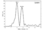
- FIG. 5 is a graph showing a cross section of the molybdenum disulfide particles shown in FIG. 6 is an extended X-ray absorption fine structure (EXAFS) profile of the molybdenum K absorption edge measured using the molybdenum disulfide particles obtained in Synthesis Example 1.
- EXAFS extended X-ray absorption fine structure
- the radioactive substance adsorbent according to this embodiment contains a metal sulfide, and is preferably composed of a metal sulfide.
- the radioactive substance adsorbent of this embodiment has selectivity for radioactive substances and exhibits high adsorption performance for radioactive substances.
- the metal sulfide preferably contains molybdenum disulfide particles as a main component, and is more preferably composed of molybdenum disulfide particles. It is considered that the high ability to adsorb radioactive substances is due to, for example, the small median diameter D50 of the molybdenum disulfide particles of 1000 nm or less.
- the selective adsorption performance of radioactive substances is considered to be due to, for example, the sulfur element in the metal sulfide having a property of being easily adsorbed to radioactive substances.
- the form of the radioactive substance adsorbent include metal sulfide particles, and molybdenum disulfide particles are preferred.
- the metal sulfide particles preferably contain molybdenum disulfide particles and more preferably consist of molybdenum disulfide particles.
- the radioactive substance of the present embodiment may contain a radioactive isotope, for example, it may contain a stable isotope and a radioactive isotope, or it may consist of only a radioactive isotope.
- the radioactive substance adsorbent of this embodiment is particularly excellent in adsorption performance for ruthenium.
- the excellent ruthenium adsorption performance is that the median diameter D50 of the molybdenum disulfide particles is as small as 1000 nm or less, the 3R crystal structure of molybdenum disulfide, and / or the affinity between ruthenium and sulfur is very high. This is thought to be caused by
- the radioactive material to be adsorbed by the molybdenum disulfide particles is preferably one or more selected from ruthenium and cobalt, more preferably ruthenium.
- the median diameter D50 of the molybdenum disulfide particles in the radioactive substance adsorbent of the present embodiment determined by the dynamic light scattering method is, for example, 10 nm or more and 1000 nm or less. is more preferable, and 400 nm or less is particularly preferable.
- the median diameter D50 of the molybdenum disulfide particles may be 10 nm or more, 20 nm or more, or 40 nm or more.
- the median diameter D50 of the molybdenum disulfide particles is determined, for example, by a dynamic light scattering particle size distribution analyzer (Microtrack Bell, Nanotrac Wave II) or a laser diffraction particle size distribution analyzer (SALD-7000 by Shimadzu Corporation). Measured using
- the molybdenum disulfide particles in the radioactive substance adsorbent of this embodiment preferably contain the 3R crystal structure of molybdenum disulfide. Inclusion of the 3R crystal structure increases the crystal edge portion of the molybdenum disulfide particles and increases the ion adsorption sites, which is considered to contribute to further improvement of the radioactive substance adsorption performance. Moreover, by containing the 3R crystal structure, the adsorption performance of ruthenium, among other radioactive substances, is remarkably improved. It is presumed that this is due to the specific surface area derived from the nanostructure of the molybdenum disulfide particles.
- the point that the molybdenum disulfide particles contain a metastable 3R crystal structure is a peak near 39.5 ° in a profile obtained from powder X-ray diffraction (XRD) using Cu-K ⁇ rays as an X-ray source.
- XRD powder X-ray diffraction
- the peaks near 49.5° are both synthetic peaks (broad peaks) of the 2H crystal structure and the 3R crystal structure.
- the molybdenum disulfide particles in the radioactive substance adsorbent of the present embodiment preferably contain 2H crystal structure and 3R crystal structure of molybdenum disulfide.
- Generally commercially available molybdenum disulfide particles include many particles with a particle size exceeding 1 ⁇ m, and are hexagonal solids, and as shown in FIG. .
- the molybdenum disulfide particles produced through the "method for producing molybdenum trioxide particles" and "method for producing molybdenum disulfide particles” described below contain a 2H crystal structure and a 3R crystal structure, and have a median diameter of D50 . can be easily adjusted from 10 nm to 1000 nm.
- the fact that the molybdenum disulfide particles have a 2H crystal structure and a 3R crystal structure can be confirmed using, for example, Rietveld analysis software (manufactured by PANalytical, High Score Plus) that can consider the crystallite size. .
- Rietveld analysis software manufactured by PANalytical, High Score Plus
- the entire XRD diffraction profile is simulated using a crystal structure model including the crystallite size, compared with the XRD diffraction profile obtained in the experiment, and compared with the diffraction profile obtained in the experiment.
- the crystallite size can be calculated in addition to the crystal structure type and its ratio calculated by the usual Rietveld analysis.
- extended Rietveld analysis the analysis method using the high score plus is referred to as "extended Rietveld analysis”.
- the peaks near 39.5 ° and the peaks near 49.5 ° Derived from the 2H crystal structure a peak near 32.5 °, a peak near 39.5 ° and a peak near 49.5 ° derived from the 3R crystal structure, a peak near 39.5 ° and 49.5 It is preferable that the half width of the peak near ° is 1° or more.
- the molybdenum disulfide particles may contain a crystal structure other than the 2H crystal structure and 3R crystal structure of molybdenum disulfide, such as a 1H crystal structure.
- the shape of the primary particles of the molybdenum disulfide particles in a two-dimensional image taken with a transmission electron microscope (TEM) is particulate, spherical, plate-like, needle-like, string-like, ribbon-like, or sheet-like. may be included, or a combination of these shapes may be included.
- the shape of the primary particles of the molybdenum disulfide particles is preferably disk-like, ribbon-like or sheet-like.
- the shape of the primary particles of the molybdenum disulfide particles preferably has a thickness in the range of 3 nm or more, and a size in the range of 5 nm or more, as measured by an atomic force microscope (AFM).
- the shape of the primary particles of the molybdenum disulfide particles preferably has a thickness in the range of 100 nm or less, and a size in the range of 50 nm or less, as measured by an atomic force microscope (AFM). It is more preferable to have, and it is particularly preferable to have a size in the range of 20 nm or less.
- the shape of the primary particles of the molybdenum disulfide particles may have a thickness in the range of 40 nm or less, measured by an atomic force microscope (AFM), and a size in the range of 30 nm or less.
- the shape of the primary particles of the molybdenum disulfide particles is disk-like, ribbon-like or sheet-like, the specific surface area of the molybdenum disulfide particles can be increased. Further, it is preferable that the molybdenum disulfide particles have a primary particle shape of a disk, a ribbon or a sheet, and have a thickness in the range of 3 to 100 nm.
- the disk-like, ribbon-like or sheet-like means a thin layer shape.
- the aspect ratio of the primary particles of molybdenum sulfide is preferably 1.2 to 1200 on the average of 50 particles, It is more preferably 2-800, even more preferably 5-400, and particularly preferably 10-200.
- the shape, length, width, and thickness of the primary particles of 50 molybdenum disulfide particles can be measured by observation with an atomic force microscope (AFM), and the aspect ratio can be calculated from the measurement results. It is possible.
- the shape of the primary particles of the molybdenum disulfide particles is not simply spherical, but disk-like, ribbon-like or sheet-like with a large aspect ratio, thereby increasing the contact area between the molybdenum disulfide particles and the radioactive substance. can be expected, and is thought to contribute to an increase in the amount of adsorption of radioactive substances.
- the specific surface area of the molybdenum disulfide particles in the radioactive substance adsorbent of the present embodiment as measured by the BET method is preferably 10 m 2 /g or more, more preferably 30 m 2 /g or more, and more preferably 40 m 2 /g. g or more is particularly preferred.
- the specific surface area of the molybdenum disulfide particles measured by the BET method may be 300 m 2 /g or less, or 200 m 2 /g or less.
- the radioactive substance adsorbent in which the molybdenum disulfide particles in the radioactive substance adsorbent of the present embodiment have a specific surface area of 10 m 2 /g or more as measured by the BET method can increase the contact area with the radioactive substance. It is considered that the adsorption performance of the
- the intensity I of the peak due to Mo—S and the ratio (I/II) of the peak intensity II due to Mo-Mo is preferably greater than 1.0, more preferably 1.1 or more, and particularly preferably 1.2 or more .
- the crystal structure of molybdenum disulfide is the 2H crystal structure or the 3R crystal structure
- the distance between Mo—S is almost the same due to the covalent bond, so the extended X-ray absorption fine structure (EXAFS) profile of the K absorption edge of molybdenum
- the peak intensity due to Mo—S is the same.
- the 2H crystal structure of molybdenum disulfide is hexagonal, the same hexagon is located directly below the hexagon of Mo atoms at 90°, so the distance between Mo-Mo becomes closer, and Mo-Mo The resulting peak intensity II becomes stronger.
- the hexagon exists not at 90° directly below the hexagon, but at a half offset, so that the distance between Mo-Mo becomes longer, and Mo The peak intensity II due to -Mo is weakened. While the pure 2H crystal structure of molybdenum disulfide has a lower ratio (I/II), the ratio (I/II) increases as the 3R crystal structure is included.
- the hexagons of Mo atoms in each of the three layers are offset from each other by half a hexagon, so each layer It can be expected that the interaction between them will be small and that radioactive substances will be easily adsorbed.
- the conversion rate R C of molybdenum disulfide particles to MoS 2 in the radioactive substance adsorbent of this embodiment is preferably 70% or more because the presence of molybdenum trioxide is considered to have an adverse effect on the radioactive substance adsorption performance. , is more preferably 80% or more, and particularly preferably 90% or more.
- the molybdenum disulfide particles in the radioactive substance adsorbent of the present embodiment can show a conversion rate R C of nearly 100% to MoS 2 , so that other molybdenum disulfide materials that can contain molybdenum trioxide as a by-product or The radioactive substance adsorption performance can be superior to that of the precursor.
- the conversion rate R C of the molybdenum disulfide particles to MoS 2 in the radioactive substance adsorbent of the present embodiment is obtained from the profile data obtained by X-ray diffraction (XRD) measurement of the molybdenum disulfide particles, from the RIR (see below) intensity ratio) method.
- XRD X-ray diffraction
- the radioactive substance adsorbent of this embodiment can adsorb and remove radioactive substance ions, radioactive substances, or radioactive substance compounds contained in a radioactive substance-containing solution, for example, a radioactive substance-containing aqueous solution. Further, the radioactive substance adsorbent of this embodiment can adsorb and remove radioactive substances or radioactive substance compounds contained in the radioactive substance-containing gas.
- the method for producing the radioactive substance adsorbent according to this embodiment is not particularly limited, but for example, it can be produced by heating a metal oxide in the presence of a sulfur source.
- the radioactive substance adsorbent of the present embodiment is not limited to those obtained by the above-described production method, and may be commercially available metal sulfides, such as commercially available molybdenum disulfide particles, as long as the adsorption performance of the present invention can be expressed. good.
- Molybdenum disulfide particles in the radioactive substance adsorbent of the present embodiment can be produced, for example, by heating molybdenum trioxide particles at a temperature of 200 to 1000° C. in the presence of a sulfur source.
- the average particle size of the primary particles of the molybdenum trioxide particles is preferably 2 nm or more and 1000 nm or less.
- the average particle size of the primary particles of the molybdenum trioxide particles is the minimum size of the molybdenum trioxide particles that constitutes aggregates on a two-dimensional image obtained by photographing the molybdenum trioxide particles with a scanning electron microscope (SEM) or a transmission electron microscope (TEM).
- SEM scanning electron microscope
- TEM transmission electron microscope
- the average particle size of the primary particles of the molybdenum trioxide particles is preferably 1 ⁇ m or less. From the point of reactivity with sulfur, it is more preferably 600 nm or less, even more preferably 400 nm or less, and particularly preferably 200 nm or less.
- the average particle diameter of the primary particles of the molybdenum trioxide particles may be 2 nm or more, 5 nm or more, or 10 nm or more.
- the molybdenum trioxide particles used for producing the molybdenum disulfide particles in the radioactive substance adsorbent of the present embodiment are preferably composed of an aggregate of primary particles containing the ⁇ crystal structure of molybdenum trioxide.
- the molybdenum trioxide particles have better reactivity with sulfur than conventional molybdenum trioxide particles consisting of only ⁇ crystals as a crystal structure, and contain the ⁇ crystal structure of molybdenum trioxide.
- the conversion rate R C to MoS 2 can be increased.
- the ⁇ crystal structure of molybdenum trioxide is assigned to the (011) plane of the ⁇ crystal of MoO3 in the profile obtained from X-ray powder diffraction (XRD) using Cu-K ⁇ radiation as the X-ray source, (2 ⁇ : It can be confirmed by the presence of a peak near 23.01°, No. 86426 (Inorganic Crystal Structure Database, ICSD)).
- the ⁇ crystal structure of molybdenum trioxide can be confirmed by the presence of the peak of the (021) plane of the ⁇ crystal of MoO3 (2 ⁇ : around 27.32°, No. 166363 (Inorganic Crystal Structure Database, ICSD)). can.
- the molybdenum trioxide particles belong to the (011) plane of the ⁇ crystal of MoO 3 (2 ⁇ : 23.01 ° near No. 86426 (Inorganic Crystal Structure Database (ICSD))) peak intensity attributed to the (021) plane of the ⁇ crystal of MoO 3 (2 ⁇ : near 27.32 °, No. 166363 (Inorganic Crystal Structure Database (ICSD)))
- the ratio to the peak intensity ( ⁇ (011)/ ⁇ (021)) is preferably 0.1 or more.
- the peak intensity attributed to the (011) plane of the ⁇ crystal of MoO 3 and the peak intensity attributed to the (021) plane of the ⁇ crystal of MoO 3 read the maximum intensity of the peak, respectively, and the ratio ( ⁇ (011 )/ ⁇ (021)).
- the ratio ( ⁇ (011)/ ⁇ (021)) is preferably 0.1 to 10.0, more preferably 0.2 to 10.0. .4 to 10.0 are particularly preferred.
- the ⁇ crystal structure of molybdenum trioxide can also be confirmed by the presence of peaks at wavenumbers 773, 848 cm ⁇ 1 and 905 cm ⁇ 1 in the Raman spectrum obtained from Raman spectroscopy.
- the ⁇ crystal structure of molybdenum trioxide can be confirmed by the presence of peaks at wavenumbers of 663, 816 cm ⁇ 1 and 991 cm ⁇ 1 .
- the average particle diameter of the primary particles of the molybdenum trioxide particles may be 5 nm or more and 2000 nm or less.
- sulfur sources include sulfur and hydrogen sulfide, and these may be used alone or in combination.
- the method for producing molybdenum disulfide particles includes heating molybdenum trioxide particles, which are aggregates of primary particles containing a ⁇ crystal structure of molybdenum trioxide, at a temperature of 100 to 800° C. in the absence of a sulfur source, and then It may include heating at a temperature of 200-1000° C. in the presence of a sulfur source.
- the heating time in the presence of the sulfur source may be a time for the sulfurization reaction to proceed sufficiently, and may be 1 to 20 hours, 2 to 15 hours, or 3 to 10 hours.
- the charging ratio of the amount of S in the sulfur source to the amount of MoO 3 in the molybdenum trioxide particles is such that the sulfurization reaction proceeds sufficiently.
- the amount of S in the sulfur source is preferably 450 mol% or more, preferably 600 mol% or more, and preferably 700 mol% or more with respect to 100 mol% of MoO 3 in the molybdenum trioxide particles. is preferred.
- the amount of S in the sulfur source may be 3000 mol% or less, 2000 mol% or less, or 1500 mol% or less with respect to 100 mol% of MoO 3 in the molybdenum trioxide particles. good too.
- the heating temperature in the presence of the sulfur source may be a temperature at which the sulfurization reaction sufficiently proceeds, preferably 320° C. or higher, more preferably 340° C. or higher. , 360° C. or higher is particularly preferred. It may be 320 to 1000°C, 340 to 800°C, or 360 to 600°C.
- the molybdenum trioxide particles preferably have a MoO3 content of 99.5% or more as measured by X-ray fluorescence (XRF). It is possible to increase the conversion rate R 2 to MoS 2 , and obtain molybdenum disulfide of high purity and good storage stability without the risk of generating sulfides derived from impurities.
- XRF X-ray fluorescence
- the molybdenum trioxide particles preferably have a specific surface area of 10 m 2 /g or more and 100 m 2 /g or less as measured by the BET method.
- the specific surface area is preferably 10 m 2 /g, preferably 20 m 2 /g, and more preferably 30 m 2 /g because reactivity with sulfur is improved. is preferred.
- the particle size is preferably 100 m 2 /g, may be 90 m 2 /g, or may be 80 m 2 /g, because production is facilitated.
- the molybdenum trioxide particles have a radial distribution function obtained from the extended X-ray absorption fine structure (EXAFS) profile of the K absorption edge of molybdenum, the intensity I of the peak due to Mo-O and the peak due to Mo-Mo
- the ratio (I/II) to intensity II is preferably greater than 1.1.
- the ratio (I/II) is considered to be an indication that the ⁇ crystal structure of MoO3 is obtained in the molybdenum trioxide particles, and the larger the ratio (I/II), the more reactive with sulfur Excellent for
- the ratio (I/II) is preferably 1.1 to 5.0, may be 1.2 to 4.0, and may be 1.2 to 3.0. There may be.
- the molybdenum trioxide particles can be produced by vaporizing a molybdenum oxide precursor compound to form a molybdenum trioxide vapor and cooling the molybdenum trioxide vapor.
- the method for producing the molybdenum trioxide particles includes firing a raw material mixture containing a molybdenum oxide precursor compound and a metal compound other than the molybdenum oxide precursor compound, vaporizing the molybdenum oxide precursor compound, and molybdenum trioxide particles. It is preferable that the ratio of the metal compound to 100% by mass of the raw material mixture is 70% by mass or less in terms of oxide, including the formation of vapor.
- the method for producing molybdenum trioxide particles can be suitably carried out using the production apparatus 1 shown in FIG.
- FIG. 1 is a schematic diagram of an example of an apparatus used for producing the molybdenum trioxide particles that are the raw material of the molybdenum disulfide particles in this embodiment.
- a manufacturing apparatus 1 includes a firing furnace 2 for firing a molybdenum trioxide precursor compound or the raw material mixture and vaporizing the molybdenum trioxide precursor compound; It has a cross-shaped cooling pipe 3 for pulverizing molybdenum oxide vapor, and a collector 4 as a collecting means for collecting molybdenum trioxide particles pulverized in the cooling pipe 3 .
- the firing furnace 2 and the cooling pipe 3 are connected through an exhaust port 5 .
- the cooling pipe 3 is provided with an opening adjusting damper 6 for an outside air intake (not shown) at the left end, and an observation window 7 at the upper end.
- the collection machine 4 is connected to an exhaust device 8 as a first air blowing means. When the exhaust device 8 exhausts the air, the collector 4 and the cooling pipe 3 are sucked, and outside air is blown to the cooling pipe 3 from the opening adjustment damper 6 of the cooling pipe 3 . That is, the cooling pipe 3 is passively blown with air by the exhaust device 8 having a suction function.
- the manufacturing apparatus 1 may have an external cooling device 9, which makes it possible to arbitrarily control the cooling conditions of the molybdenum trioxide vapor generated from the kiln 2.
- Air is taken in from the outside air intake port by the opening adjustment damper 6, and the molybdenum trioxide vapor vaporized in the firing furnace 2 is cooled in an air atmosphere to form molybdenum trioxide particles, so that the ratio (I / II) can be greater than 1.1, and the ⁇ crystal structure of MoO3 is likely to be obtained in the molybdenum trioxide particles.
- the molybdenum trioxide precursor compound is not particularly limited as long as it forms a molybdenum trioxide vapor when fired, and includes metallic molybdenum, molybdenum trioxide, molybdenum dioxide, molybdenum sulfide, ammonium molybdate, and phosphomolybdic acid.
- molybdenum trioxide precursor compounds may be used alone or in combination of two or more.
- the form of the molybdenum trioxide precursor compound is not particularly limited, and may be, for example, powder such as molybdenum trioxide, or liquid such as an aqueous ammonium molybdate solution. Preferably, it is in the form of powder, which is easy to handle and energy efficient.
- molybdenum trioxide precursor compound it is preferable to use commercially available ⁇ -crystalline molybdenum trioxide. Further, when ammonium molybdate is used as the molybdenum oxide precursor compound, it is converted to thermodynamically stable molybdenum trioxide by firing, so the molybdenum oxide precursor compound to be vaporized is the molybdenum trioxide. .
- Molybdenum trioxide vapor can also be formed by firing a raw material mixture containing a molybdenum oxide precursor compound and a metal compound other than the molybdenum oxide precursor compound.
- the molybdenum oxide precursor compound preferably contains molybdenum trioxide in terms of ease of control of the purity of the obtained molybdenum trioxide particles, the average particle size of the primary particles, and the crystal structure.
- a molybdenum oxide precursor compound and a metal compound other than the molybdenum oxide precursor compound may sometimes form an intermediate. It can be vaporized in the form
- the content of the molybdenum oxide precursor compound with respect to 100% by mass of the raw material mixture is 40 to 100 mass%. %, may be 45 to 100% by mass, or may be 50 to 100% by mass.
- the firing temperature varies depending on the molybdenum oxide precursor compound, the metal compound, and the desired molybdenum trioxide particles used, it is usually preferable to set the temperature at which the intermediates can be decomposed.
- the temperature is preferably 500 to 1500 ° C. It is more preferably 600 to 1550°C, even more preferably 700 to 1600°C.
- the firing time is also not particularly limited, and can be, for example, 1 min to 30 hours, 10 min to 25 hours, or 100 min to 20 hours.
- the rate of temperature increase varies depending on the properties of the molybdenum oxide precursor compound used, the metal compound, and the desired molybdenum trioxide particles. It is preferably 1° C./min or more and 50° C./min or less, more preferably 2° C./min or more and 10° C./min or less.
- the molybdenum trioxide vapor is then cooled and granulated. Cooling of the molybdenum trioxide vapor is performed by lowering the temperature of the cooling pipe.
- the cooling means includes cooling by blowing gas into the cooling pipe, cooling by a cooling mechanism provided in the cooling pipe, and cooling by an external cooling device, as described above.
- Cooling of the molybdenum trioxide vapor is preferably carried out in an air atmosphere.
- the ratio (I/II) can be made larger than 1.1, and in the molybdenum trioxide particles, ⁇ crystals of MoO 3 Easy to obtain structure.
- the cooling temperature (the temperature of the cooling pipe) is not particularly limited, but is preferably -100 to 600°C, more preferably -50 to 400°C.
- the cooling rate of the molybdenum trioxide vapor is not particularly limited, it is preferably 100°C/s or more and 100000°C/s or less, more preferably 1000°C/s or more and 50000°C/s or less. There is a tendency that molybdenum trioxide particles having a smaller particle size and a larger specific surface area can be obtained as the cooling rate of the molybdenum trioxide vapor increases.
- the temperature of the blown gas is preferably -100 to 300°C, more preferably -50 to 100°C.
- the particles obtained by cooling the molybdenum trioxide vapor are transported to and collected by the collector.
- the particles obtained by cooling the molybdenum trioxide vapor may be fired again at a temperature of 100 to 320°C.
- the molybdenum trioxide particles obtained by the method for producing molybdenum trioxide particles may be fired again at a temperature of 100 to 320°C.
- the firing temperature for the second firing may be 120 to 280.degree. C. or 140 to 240.degree.
- the firing time for the second firing can be, for example, 1 min to 4 hours, 10 min to 5 hours, or 100 min to 6 hours.
- part of the ⁇ crystal structure of molybdenum trioxide disappears, and when fired at a temperature of 350 ° C. or higher for 4 hours, the ⁇ crystal structure in the molybdenum trioxide particles disappears. , the ratio ( ⁇ (011)/ ⁇ (021)) becomes 0 and the reactivity with sulfur is impaired.
- Molybdenum disulfide particles in the radioactive substance adsorbent of this embodiment can be produced by the method for producing the radioactive substance adsorbent.
- molybdenum trioxide particles suitable for producing molybdenum disulfide particles in the radioactive substance adsorbent of the present embodiment can be produced by the method for producing molybdenum trioxide particles.
- R C (%) ( IA / KA )/( ⁇ (IB/ KB )) ⁇ 100 (1)
- the RIR values used were the values described in the Inorganic Crystal Structure Database (ICSD), and the integrated powder X-ray analysis software (PDXL) (manufactured by Rigaku Corporation) was used for the analysis.
- EXAFS Extra X-ray absorption fine structure
- the solution is prepared in the same manner, and particles with a particle size in the range of 0.015 to 500 ⁇ m are measured using a laser diffraction particle size distribution analyzer (SALD-7000, manufactured by Shimadzu Corporation). The size distribution was measured and the median diameter D50 was calculated.
- SALD-7000 laser diffraction particle size distribution analyzer
- Molybdenum disulfide particles were measured with an atomic force microscope (AFM) (Oxford Cypher-ES) to observe the particle shape.
- Example 1 As molybdenum disulfide particles used in Example 1, the result of the X-ray diffraction pattern of a commercially available molybdenum disulfide reagent (manufactured by Kanto Kagaku Co., Ltd.) is shown in FIG. 2 together with the diffraction pattern of molybdenum disulfide with a 2H crystal structure. .
- the molybdenum disulfide reagent of Example 1 was found to be molybdenum disulfide with a 2H crystal structure of 99% or more.
- the half widths of the peak near 39.5° and the peak near 49.5° were 0.23° and 0.22°, respectively.
- the specific surface area (SA), the intensity of the peak due to Mo—S obtained from the measurement of the extended X-ray absorption fine structure (EXAFS) of the K absorption edge of molybdenum, I and the peak intensity II due to Mo—Mo (I/II) was 1.2.
- the specific surface area of the molybdenum disulfide particles used in Example 1 was measured by the BET method and found to be 5.6 m 2 /g. Further, the particle size distribution of the molybdenum disulfide particles used in Example 1 was measured by a dynamic light scattering particle size distribution analyzer, and the median diameter D50 was determined to be 13340 nm.
- ⁇ Synthesis Example 1> (Production of molybdenum trioxide particles) 1 kg of transitional aluminum oxide (manufactured by Wako Pure Chemical Industries, Ltd., activated alumina, average particle size 45 ⁇ m) and 1 kg of molybdenum trioxide (manufactured by Taiyo Koko Co., Ltd.) are mixed, then charged into a sachet, and the production apparatus shown in FIG. 1 was fired at a temperature of 1100° C. for 10 hours in the firing furnace 2. During firing, outside air (blowing speed: 50 L/min, outside air temperature: 25° C.) was introduced from the side and bottom surfaces of the firing furnace 2 .
- outside air blow speed: 50 L/min, outside air temperature: 25° C.
- Molybdenum trioxide was evaporated in the calcining furnace 2, cooled in the vicinity of the collector 4, and precipitated as particles.
- a RHK simulator manufactured by Noritake Co., Ltd.
- VF-5N dust collector manufactured by Amano
- the specific surface area of the molybdenum disulfide particles of Synthesis Example 1 was measured by the BET method and found to be 67.8 m 2 /g.
- the particle size distribution of the molybdenum disulfide particles of Synthesis Example 1 was measured with a dynamic light scattering particle size distribution analyzer, and the median diameter D50 was determined to be 170 nm.
- FIG. 4 is an AFM image obtained by the measurement, showing the upper surface of the molybdenum disulfide particles.
- FIG. 5 is a graph showing a cross section of the molybdenum disulfide particles shown in FIG.
- the thickness (height) was obtained from this cross-sectional view, it was 16 nm. Therefore, the aspect ratio (length (longitudinal)/thickness (height)) of the primary particles of the molybdenum disulfide particles was 11.25.
- Table 1 shows representative examples of AFM measurement results of molybdenum disulfide particles.
- molybdenum disulfide particles (1) are molybdenum disulfide particles shown in FIG.
- Molybdenum disulfide particles (2) are the particles with the longest length among the measured molybdenum disulfide particles
- Molybdenum disulfide particles (3) are the particles with the shortest length.
- Molybdenum disulfide particles (4) are relatively thick particles
- “Molybdenum disulfide particles (5)” are the thinnest particles.
- Molybdenum disulfide particles (6) are particles with the largest aspect ratio.
- Molybdenum disulfide particles (7) are particles having the largest thickness and the smallest aspect ratio.
- the extended X-ray absorption fine structure (EXAFS) of the molybdenum disulfide particles of Synthesis Example 1 was measured.
- the extended X-ray absorption fine structure (EXAFS) profile of the K-edge of molybdenum is shown in FIG. In the radial distribution function obtained from this profile, the ratio (I/II) between the peak intensity I due to Mo--S and the peak intensity II due to Mo--Mo was 1.2.
- Example 1 [Radioactive substance (ruthenium) adsorption evaluation] ⁇ Example 1> A 1000 ppm ruthenium standard solution (manufactured by ACROS ORGANICS) was diluted with ion-exchanged water, and an aqueous sodium hydroxide solution was used to prepare a solution to be adsorbed so that the pH was 3.5 and the initial ruthenium concentration was about 1000 ppb.
- the sample solution was filtered with a 0.2 ⁇ m syringe filter, and the concentration of ruthenium remaining in the sample solution was quantified with an ICP emission spectrometer (ICP-OES, Optima8300, manufactured by PerkinElmer). Also, using the residual ruthenium concentration in the sample solution after 24 hours and the input amount of molybdenum disulfide powder, the amount of ruthenium adsorbed per 1 g of adsorbent for 24 hours (g/g) was calculated from the following formula.
- Amount of ruthenium adsorbed for 24 hours (initial ruthenium concentration ⁇ ruthenium concentration after 24 hours) ⁇ liquid volume/amount of molybdenum disulfide powder charged
- Adsorption rate (initial ruthenium concentration - ruthenium concentration after 24 hours) / initial ruthenium concentration x 100
- Example 2 In the same manner as in Example 1, except that the molybdenum disulfide powder obtained in Synthesis Example 1 was used instead of the commercially available molybdenum disulfide powder, the ruthenium residual concentration in the sample solution after 24 hours and the adsorbent The amount of ruthenium adsorbed per 1 g for 24 hours was calculated.
- Example 2 From the results in Table 2, in Example 1, when 30 mg of commercially available molybdenum disulfide powder was used as the adsorbent, the ruthenium concentration in the solution after 24 hours was 80 ppb, the ruthenium adsorption amount was 0.69 g / g, and the ruthenium adsorption The ruthenium adsorption rate was 89.6%, indicating that the ruthenium adsorption rate was high and good adsorption performance was exhibited.
- Example 2 when 30 mg of the molybdenum disulfide powder of Synthesis Example 1 was used, the ruthenium concentration in the solution after 24 hours was 67 ppb, the ruthenium adsorption amount was 0.70 g/g, and the ruthenium adsorption rate was 91.3%. , and it was found that the ruthenium adsorption rate was higher than that of Example 1 and that better adsorption performance was exhibited.
- Comparative Example 1 when 30 mg of carbon was used as the adsorbent, the ruthenium concentration in the solution after 24 hours was 271 ppb, the ruthenium adsorption amount was 0.50 g/g, and the ruthenium adsorption rate was 64.7%. As compared with Examples 3 and 4 in which molybdenum disulfide powder was used as an adsorbent, the ruthenium adsorption rate was low and the adsorption performance was inferior.
- the radioactive substance adsorbent of the present invention has a high adsorption performance for radioactive substances, it can be suitably used as a radioactive substance adsorption material when adsorbing radioactive substances from radioactive waste liquids from nuclear facilities and the like. Among them, it can be particularly suitably used as a material for adsorbing ruthenium from radioactive waste liquids containing ruthenium at high to low concentrations because of its remarkably excellent adsorption performance for ruthenium. In addition, since the radioactive substance adsorption method of the present invention can easily adsorb radioactive substances, it is extremely useful as a method for adsorbing radioactive substances from contaminated water or the like generated from nuclear facilities or the like.
Landscapes
- Chemical & Material Sciences (AREA)
- Analytical Chemistry (AREA)
- Organic Chemistry (AREA)
- Chemical Kinetics & Catalysis (AREA)
- Physics & Mathematics (AREA)
- Engineering & Computer Science (AREA)
- General Engineering & Computer Science (AREA)
- High Energy & Nuclear Physics (AREA)
- Inorganic Chemistry (AREA)
- Solid-Sorbent Or Filter-Aiding Compositions (AREA)
- Inorganic Compounds Of Heavy Metals (AREA)
Priority Applications (1)
| Application Number | Priority Date | Filing Date | Title |
|---|---|---|---|
| JP2022571744A JP7255760B2 (ja) | 2021-03-24 | 2022-03-22 | 放射性物質吸着剤 |
Applications Claiming Priority (2)
| Application Number | Priority Date | Filing Date | Title |
|---|---|---|---|
| JP2021050487 | 2021-03-24 | ||
| JP2021-050487 | 2021-03-24 |
Publications (1)
| Publication Number | Publication Date |
|---|---|
| WO2022202758A1 true WO2022202758A1 (ja) | 2022-09-29 |
Family
ID=83397367
Family Applications (1)
| Application Number | Title | Priority Date | Filing Date |
|---|---|---|---|
| PCT/JP2022/012994 Ceased WO2022202758A1 (ja) | 2021-03-24 | 2022-03-22 | 放射性物質吸着剤 |
Country Status (2)
| Country | Link |
|---|---|
| JP (1) | JP7255760B2 (https=) |
| WO (1) | WO2022202758A1 (https=) |
Cited By (1)
| Publication number | Priority date | Publication date | Assignee | Title |
|---|---|---|---|---|
| WO2025109873A1 (ja) * | 2023-11-24 | 2025-05-30 | Dic株式会社 | 三酸化モリブデン微粒子の製造方法 |
Citations (5)
| Publication number | Priority date | Publication date | Assignee | Title |
|---|---|---|---|---|
| JP2013002865A (ja) * | 2011-06-14 | 2013-01-07 | Dainichiseika Color & Chem Mfg Co Ltd | 吸着剤組成物、放射性セシウム吸着剤及びそれを用いた放射性セシウムの分離方法 |
| JP2014517306A (ja) * | 2011-06-03 | 2014-07-17 | ダウ グローバル テクノロジーズ エルエルシー | ポリマーのクロマトグラフィー |
| US9056263B2 (en) * | 2010-05-25 | 2015-06-16 | Northwestern University | Chalcogenide compounds for the remediation of nuclear and heavy metal wastes |
| JP2019527125A (ja) * | 2016-06-16 | 2019-09-26 | クリオン、インコーポレイテッド | 水性毒性廃棄物捕捉の性能を制御するシステム及び方法 |
| WO2019181723A1 (ja) * | 2018-03-19 | 2019-09-26 | Dic株式会社 | モリブデン硫化物、その製造方法及び水素発生触媒 |
Family Cites Families (1)
| Publication number | Priority date | Publication date | Assignee | Title |
|---|---|---|---|---|
| CN112266098B (zh) * | 2020-10-12 | 2023-03-24 | 东华理工大学 | 一种利用助剂提升吸咐剂吸附性能的方法 |
-
2022
- 2022-03-22 JP JP2022571744A patent/JP7255760B2/ja active Active
- 2022-03-22 WO PCT/JP2022/012994 patent/WO2022202758A1/ja not_active Ceased
Patent Citations (5)
| Publication number | Priority date | Publication date | Assignee | Title |
|---|---|---|---|---|
| US9056263B2 (en) * | 2010-05-25 | 2015-06-16 | Northwestern University | Chalcogenide compounds for the remediation of nuclear and heavy metal wastes |
| JP2014517306A (ja) * | 2011-06-03 | 2014-07-17 | ダウ グローバル テクノロジーズ エルエルシー | ポリマーのクロマトグラフィー |
| JP2013002865A (ja) * | 2011-06-14 | 2013-01-07 | Dainichiseika Color & Chem Mfg Co Ltd | 吸着剤組成物、放射性セシウム吸着剤及びそれを用いた放射性セシウムの分離方法 |
| JP2019527125A (ja) * | 2016-06-16 | 2019-09-26 | クリオン、インコーポレイテッド | 水性毒性廃棄物捕捉の性能を制御するシステム及び方法 |
| WO2019181723A1 (ja) * | 2018-03-19 | 2019-09-26 | Dic株式会社 | モリブデン硫化物、その製造方法及び水素発生触媒 |
Non-Patent Citations (1)
| Title |
|---|
| MANOS MANOLIS J., DING NAN, KANATZIDIS MERCOURI G.: "Layered metal sulfides: Exceptionally selective agents for radioactive strontium removal", PROCEEDINGS OF THE NATIONAL ACADEMY OF SCIENCES, NATIONAL ACADEMY OF SCIENCES, vol. 105, no. 10, 11 March 2008 (2008-03-11), pages 3696 - 3699, XP055970206, ISSN: 0027-8424, DOI: 10.1073/pnas.0711528105 * |
Cited By (3)
| Publication number | Priority date | Publication date | Assignee | Title |
|---|---|---|---|---|
| WO2025109873A1 (ja) * | 2023-11-24 | 2025-05-30 | Dic株式会社 | 三酸化モリブデン微粒子の製造方法 |
| JPWO2025109873A1 (https=) * | 2023-11-24 | 2025-05-30 | ||
| JP7846471B2 (ja) | 2023-11-24 | 2026-04-15 | Dic株式会社 | 三酸化モリブデン微粒子の製造方法 |
Also Published As
| Publication number | Publication date |
|---|---|
| JPWO2022202758A1 (https=) | 2022-09-29 |
| JP7255760B2 (ja) | 2023-04-11 |
Similar Documents
| Publication | Publication Date | Title |
|---|---|---|
| JP7060170B2 (ja) | 硫化モリブデン粉体及びその製造方法、重金属吸着剤、光熱変換材料、蒸留方法、酸素還元触媒、並びに触媒インク | |
| Yin et al. | Characterization of Co-doped birnessites and application for removal of lead and arsenite | |
| US12497303B2 (en) | Molybdenum trioxide powder and method for producing same | |
| KR20220112802A (ko) | 나트륨 페라이트 입자 분말 및 그 제조 방법 | |
| Nenadović et al. | Mechanochemical treatment and structural properties of lead adsorption on kaolinite (Rudovci, Serbia) | |
| JP7255760B2 (ja) | 放射性物質吸着剤 | |
| JP6099040B2 (ja) | 複合化層状複水酸化物 | |
| JP7274207B2 (ja) | 層状複水酸化物の花冠状凝集粒子を含むカラム用充填材及びこれを充填した分離デバイス | |
| JP7460015B2 (ja) | 貴金属吸着剤、貴金属回収方法及び貴金属吸着剤の再生方法 | |
| JP2022041132A (ja) | 二酸化炭素吸着剤、二酸化炭素吸着剤の再生方法、および、層状金属水酸化物の製造方法 | |
| JP4189652B2 (ja) | 吸着剤 | |
| CN117062776B (zh) | 钼化合物和其制造方法 | |
| JP7638899B2 (ja) | 層状マンガン酸化物成形体およびその製造方法 | |
| JP5099349B2 (ja) | 吸着剤 | |
| JP4238111B2 (ja) | フッ素イオン回収材の製造方法及びフッ素イオンの回収方法 | |
| JP5099348B2 (ja) | 吸着剤 | |
| JP7188664B1 (ja) | 三酸化モリブデン粉体及びその製造方法 | |
| Ni et al. | Synthesis of platy potassium magnesium titanate and its application in removal of copper ions from aqueous solution | |
| Liu et al. | Enhanced Cesium Removal through Heterogeneous Chemical Precipitation on Modified Magnesium Silicate Mineral. | |
| WO2025022983A1 (ja) | カラム構造体 | |
| CN114259987A (zh) | 花生壳/羟基磷灰石复合材料及其制备方法和在吸附分离Pb(II)中的应用 | |
| JP2021087931A (ja) | ストロンチウム含有廃液の処理方法 |
Legal Events
| Date | Code | Title | Description |
|---|---|---|---|
| 121 | Ep: the epo has been informed by wipo that ep was designated in this application |
Ref document number: 22775542 Country of ref document: EP Kind code of ref document: A1 |
|
| ENP | Entry into the national phase |
Ref document number: 2022571744 Country of ref document: JP Kind code of ref document: A |
|
| NENP | Non-entry into the national phase |
Ref country code: DE |
|
| 122 | Ep: pct application non-entry in european phase |
Ref document number: 22775542 Country of ref document: EP Kind code of ref document: A1 |