WO2022202758A1 - 放射性物質吸着剤 - Google Patents
放射性物質吸着剤 Download PDFInfo
- Publication number
- WO2022202758A1 WO2022202758A1 PCT/JP2022/012994 JP2022012994W WO2022202758A1 WO 2022202758 A1 WO2022202758 A1 WO 2022202758A1 JP 2022012994 W JP2022012994 W JP 2022012994W WO 2022202758 A1 WO2022202758 A1 WO 2022202758A1
- Authority
- WO
- WIPO (PCT)
- Prior art keywords
- particles
- molybdenum disulfide
- molybdenum
- radioactive substance
- disulfide particles
- Prior art date
Links
- 239000000941 radioactive substance Substances 0.000 title claims abstract description 93
- 239000003463 adsorbent Substances 0.000 title claims abstract description 71
- 239000002245 particle Substances 0.000 claims abstract description 221
- CWQXQMHSOZUFJS-UHFFFAOYSA-N molybdenum disulfide Chemical compound S=[Mo]=S CWQXQMHSOZUFJS-UHFFFAOYSA-N 0.000 claims abstract description 158
- 229910052982 molybdenum disulfide Inorganic materials 0.000 claims abstract description 153
- 229910052976 metal sulfide Inorganic materials 0.000 claims abstract description 15
- 239000013078 crystal Substances 0.000 claims description 80
- 229910052707 ruthenium Inorganic materials 0.000 claims description 61
- KJTLSVCANCCWHF-UHFFFAOYSA-N Ruthenium Chemical compound [Ru] KJTLSVCANCCWHF-UHFFFAOYSA-N 0.000 claims description 59
- 239000011164 primary particle Substances 0.000 claims description 33
- 238000010521 absorption reaction Methods 0.000 claims description 17
- 238000002441 X-ray diffraction Methods 0.000 claims description 16
- 238000000034 method Methods 0.000 claims description 16
- 238000004438 BET method Methods 0.000 claims description 11
- ZOKXTWBITQBERF-UHFFFAOYSA-N Molybdenum Chemical compound [Mo] ZOKXTWBITQBERF-UHFFFAOYSA-N 0.000 claims description 11
- 239000011733 molybdenum Substances 0.000 claims description 11
- 229910052750 molybdenum Inorganic materials 0.000 claims description 11
- 229910017311 Mo—Mo Inorganic materials 0.000 claims description 8
- 238000002296 dynamic light scattering Methods 0.000 claims description 7
- 238000005315 distribution function Methods 0.000 claims description 5
- 238000000634 powder X-ray diffraction Methods 0.000 claims description 5
- 239000012857 radioactive material Substances 0.000 claims description 5
- 238000001179 sorption measurement Methods 0.000 abstract description 53
- JKQOBWVOAYFWKG-UHFFFAOYSA-N molybdenum trioxide Chemical compound O=[Mo](=O)=O JKQOBWVOAYFWKG-UHFFFAOYSA-N 0.000 description 224
- 238000001816 cooling Methods 0.000 description 35
- 238000004519 manufacturing process Methods 0.000 description 26
- 150000001875 compounds Chemical class 0.000 description 25
- 239000002243 precursor Substances 0.000 description 24
- NINIDFKCEFEMDL-UHFFFAOYSA-N Sulfur Chemical compound [S] NINIDFKCEFEMDL-UHFFFAOYSA-N 0.000 description 22
- 229910052717 sulfur Inorganic materials 0.000 description 22
- 238000010304 firing Methods 0.000 description 21
- 239000000843 powder Substances 0.000 description 21
- 239000011593 sulfur Substances 0.000 description 21
- 229910000476 molybdenum oxide Inorganic materials 0.000 description 20
- PQQKPALAQIIWST-UHFFFAOYSA-N oxomolybdenum Chemical compound [Mo]=O PQQKPALAQIIWST-UHFFFAOYSA-N 0.000 description 20
- 238000005259 measurement Methods 0.000 description 15
- 230000015572 biosynthetic process Effects 0.000 description 13
- 239000000243 solution Substances 0.000 description 13
- 238000003786 synthesis reaction Methods 0.000 description 12
- 239000000203 mixture Substances 0.000 description 11
- 239000002994 raw material Substances 0.000 description 11
- 238000006243 chemical reaction Methods 0.000 description 10
- QXYJCZRRLLQGCR-UHFFFAOYSA-N dioxomolybdenum Chemical compound O=[Mo]=O QXYJCZRRLLQGCR-UHFFFAOYSA-N 0.000 description 10
- 238000009826 distribution Methods 0.000 description 10
- MEFBJEMVZONFCJ-UHFFFAOYSA-N molybdate Chemical compound [O-][Mo]([O-])(=O)=O MEFBJEMVZONFCJ-UHFFFAOYSA-N 0.000 description 10
- 239000000523 sample Substances 0.000 description 9
- 239000007788 liquid Substances 0.000 description 8
- 150000002736 metal compounds Chemical class 0.000 description 8
- XLYOFNOQVPJJNP-UHFFFAOYSA-N water Substances O XLYOFNOQVPJJNP-UHFFFAOYSA-N 0.000 description 8
- 238000004458 analytical method Methods 0.000 description 7
- 150000002500 ions Chemical class 0.000 description 7
- 238000010438 heat treatment Methods 0.000 description 6
- 239000000463 material Substances 0.000 description 6
- 238000000089 atomic force micrograph Methods 0.000 description 4
- 238000007664 blowing Methods 0.000 description 4
- 210000004027 cell Anatomy 0.000 description 4
- 239000007806 chemical reaction intermediate Substances 0.000 description 4
- 230000000052 comparative effect Effects 0.000 description 4
- 239000007789 gas Substances 0.000 description 4
- 230000002285 radioactive effect Effects 0.000 description 4
- 239000002901 radioactive waste Substances 0.000 description 4
- 230000009257 reactivity Effects 0.000 description 4
- 239000012488 sample solution Substances 0.000 description 4
- 238000004876 x-ray fluorescence Methods 0.000 description 4
- IJGRMHOSHXDMSA-UHFFFAOYSA-N Atomic nitrogen Chemical compound N#N IJGRMHOSHXDMSA-UHFFFAOYSA-N 0.000 description 3
- HEMHJVSKTPXQMS-UHFFFAOYSA-M Sodium hydroxide Chemical compound [OH-].[Na+] HEMHJVSKTPXQMS-UHFFFAOYSA-M 0.000 description 3
- APUPEJJSWDHEBO-UHFFFAOYSA-P ammonium molybdate Chemical compound [NH4+].[NH4+].[O-][Mo]([O-])(=O)=O APUPEJJSWDHEBO-UHFFFAOYSA-P 0.000 description 3
- 239000011609 ammonium molybdate Substances 0.000 description 3
- 235000018660 ammonium molybdate Nutrition 0.000 description 3
- 229940010552 ammonium molybdate Drugs 0.000 description 3
- 239000012298 atmosphere Substances 0.000 description 3
- 230000005540 biological transmission Effects 0.000 description 3
- 239000013522 chelant Substances 0.000 description 3
- 239000003153 chemical reaction reagent Substances 0.000 description 3
- HNPSIPDUKPIQMN-UHFFFAOYSA-N dioxosilane;oxo(oxoalumanyloxy)alumane Chemical compound O=[Si]=O.O=[Al]O[Al]=O HNPSIPDUKPIQMN-UHFFFAOYSA-N 0.000 description 3
- 239000000543 intermediate Substances 0.000 description 3
- 239000010410 layer Substances 0.000 description 3
- TWNQGVIAIRXVLR-UHFFFAOYSA-N oxo(oxoalumanyloxy)alumane Chemical compound O=[Al]O[Al]=O TWNQGVIAIRXVLR-UHFFFAOYSA-N 0.000 description 3
- 239000011347 resin Substances 0.000 description 3
- 229920005989 resin Polymers 0.000 description 3
- 238000005987 sulfurization reaction Methods 0.000 description 3
- 230000008016 vaporization Effects 0.000 description 3
- XEFUJGURFLOFAN-UHFFFAOYSA-N 1,3-dichloro-5-isocyanatobenzene Chemical compound ClC1=CC(Cl)=CC(N=C=O)=C1 XEFUJGURFLOFAN-UHFFFAOYSA-N 0.000 description 2
- CSCPPACGZOOCGX-UHFFFAOYSA-N Acetone Chemical compound CC(C)=O CSCPPACGZOOCGX-UHFFFAOYSA-N 0.000 description 2
- OKTJSMMVPCPJKN-UHFFFAOYSA-N Carbon Chemical compound [C] OKTJSMMVPCPJKN-UHFFFAOYSA-N 0.000 description 2
- 241000084008 Cyanidiales Species 0.000 description 2
- XEEYBQQBJWHFJM-UHFFFAOYSA-N Iron Chemical compound [Fe] XEEYBQQBJWHFJM-UHFFFAOYSA-N 0.000 description 2
- 238000003991 Rietveld refinement Methods 0.000 description 2
- 229910021536 Zeolite Inorganic materials 0.000 description 2
- -1 aluminum compound Chemical class 0.000 description 2
- QVGXLLKOCUKJST-UHFFFAOYSA-N atomic oxygen Chemical compound [O] QVGXLLKOCUKJST-UHFFFAOYSA-N 0.000 description 2
- 239000006227 byproduct Substances 0.000 description 2
- 229910052799 carbon Inorganic materials 0.000 description 2
- 229910017052 cobalt Inorganic materials 0.000 description 2
- 239000010941 cobalt Substances 0.000 description 2
- GUTLYIVDDKVIGB-UHFFFAOYSA-N cobalt atom Chemical compound [Co] GUTLYIVDDKVIGB-UHFFFAOYSA-N 0.000 description 2
- 239000010949 copper Substances 0.000 description 2
- 229920006037 cross link polymer Polymers 0.000 description 2
- 238000010586 diagram Methods 0.000 description 2
- 238000002474 experimental method Methods 0.000 description 2
- AMWRITDGCCNYAT-UHFFFAOYSA-L hydroxy(oxo)manganese;manganese Chemical compound [Mn].O[Mn]=O.O[Mn]=O AMWRITDGCCNYAT-UHFFFAOYSA-L 0.000 description 2
- 230000006872 improvement Effects 0.000 description 2
- 239000012299 nitrogen atmosphere Substances 0.000 description 2
- 229910052760 oxygen Inorganic materials 0.000 description 2
- 239000001301 oxygen Substances 0.000 description 2
- 239000000047 product Substances 0.000 description 2
- 238000011084 recovery Methods 0.000 description 2
- 238000003756 stirring Methods 0.000 description 2
- 239000000126 substance Substances 0.000 description 2
- 238000012360 testing method Methods 0.000 description 2
- 239000010457 zeolite Substances 0.000 description 2
- 208000000659 Autoimmune lymphoproliferative syndrome Diseases 0.000 description 1
- 229910052582 BN Inorganic materials 0.000 description 1
- ZOXJGFHDIHLPTG-UHFFFAOYSA-N Boron Chemical compound [B] ZOXJGFHDIHLPTG-UHFFFAOYSA-N 0.000 description 1
- PZNSFCLAULLKQX-UHFFFAOYSA-N Boron nitride Chemical compound N#B PZNSFCLAULLKQX-UHFFFAOYSA-N 0.000 description 1
- 101100069231 Caenorhabditis elegans gkow-1 gene Proteins 0.000 description 1
- VYZAMTAEIAYCRO-UHFFFAOYSA-N Chromium Chemical compound [Cr] VYZAMTAEIAYCRO-UHFFFAOYSA-N 0.000 description 1
- RYGMFSIKBFXOCR-UHFFFAOYSA-N Copper Chemical compound [Cu] RYGMFSIKBFXOCR-UHFFFAOYSA-N 0.000 description 1
- RWSOTUBLDIXVET-UHFFFAOYSA-N Dihydrogen sulfide Chemical compound S RWSOTUBLDIXVET-UHFFFAOYSA-N 0.000 description 1
- PWHULOQIROXLJO-UHFFFAOYSA-N Manganese Chemical compound [Mn] PWHULOQIROXLJO-UHFFFAOYSA-N 0.000 description 1
- 229910017299 Mo—O Inorganic materials 0.000 description 1
- 239000004698 Polyethylene Substances 0.000 description 1
- ZLMJMSJWJFRBEC-UHFFFAOYSA-N Potassium Chemical compound [K] ZLMJMSJWJFRBEC-UHFFFAOYSA-N 0.000 description 1
- 238000001069 Raman spectroscopy Methods 0.000 description 1
- 238000001237 Raman spectrum Methods 0.000 description 1
- 241000206572 Rhodophyta Species 0.000 description 1
- XUIMIQQOPSSXEZ-UHFFFAOYSA-N Silicon Chemical compound [Si] XUIMIQQOPSSXEZ-UHFFFAOYSA-N 0.000 description 1
- 241001168730 Simo Species 0.000 description 1
- UCKMPCXJQFINFW-UHFFFAOYSA-N Sulphide Chemical compound [S-2] UCKMPCXJQFINFW-UHFFFAOYSA-N 0.000 description 1
- RTAQQCXQSZGOHL-UHFFFAOYSA-N Titanium Chemical compound [Ti] RTAQQCXQSZGOHL-UHFFFAOYSA-N 0.000 description 1
- 238000000833 X-ray absorption fine structure spectroscopy Methods 0.000 description 1
- HCHKCACWOHOZIP-UHFFFAOYSA-N Zinc Chemical compound [Zn] HCHKCACWOHOZIP-UHFFFAOYSA-N 0.000 description 1
- QCWXUUIWCKQGHC-UHFFFAOYSA-N Zirconium Chemical compound [Zr] QCWXUUIWCKQGHC-UHFFFAOYSA-N 0.000 description 1
- 239000002253 acid Substances 0.000 description 1
- 230000002411 adverse Effects 0.000 description 1
- 229910052782 aluminium Inorganic materials 0.000 description 1
- PNEYBMLMFCGWSK-UHFFFAOYSA-N aluminium oxide Inorganic materials [O-2].[O-2].[O-2].[Al+3].[Al+3] PNEYBMLMFCGWSK-UHFFFAOYSA-N 0.000 description 1
- 150000001408 amides Chemical class 0.000 description 1
- 229910052787 antimony Inorganic materials 0.000 description 1
- WATWJIUSRGPENY-UHFFFAOYSA-N antimony atom Chemical compound [Sb] WATWJIUSRGPENY-UHFFFAOYSA-N 0.000 description 1
- 239000007864 aqueous solution Substances 0.000 description 1
- RCMWGBKVFBTLCW-UHFFFAOYSA-N barium(2+);dioxido(dioxo)molybdenum Chemical compound [Ba+2].[O-][Mo]([O-])(=O)=O RCMWGBKVFBTLCW-UHFFFAOYSA-N 0.000 description 1
- 239000011230 binding agent Substances 0.000 description 1
- 229910052796 boron Inorganic materials 0.000 description 1
- 238000001354 calcination Methods 0.000 description 1
- 238000004364 calculation method Methods 0.000 description 1
- PBAYDYUZOSNJGU-UHFFFAOYSA-N chelidonic acid Natural products OC(=O)C1=CC(=O)C=C(C(O)=O)O1 PBAYDYUZOSNJGU-UHFFFAOYSA-N 0.000 description 1
- 239000003795 chemical substances by application Substances 0.000 description 1
- 229910052804 chromium Inorganic materials 0.000 description 1
- 239000011651 chromium Substances 0.000 description 1
- 239000003245 coal Substances 0.000 description 1
- 238000004581 coalescence Methods 0.000 description 1
- KYYSIVCCYWZZLR-UHFFFAOYSA-N cobalt(2+);dioxido(dioxo)molybdenum Chemical compound [Co+2].[O-][Mo]([O-])(=O)=O KYYSIVCCYWZZLR-UHFFFAOYSA-N 0.000 description 1
- 239000000498 cooling water Substances 0.000 description 1
- 229910052802 copper Inorganic materials 0.000 description 1
- IKUPISAYGBGQDT-UHFFFAOYSA-N copper;dioxido(dioxo)molybdenum Chemical compound [Cu+2].[O-][Mo]([O-])(=O)=O IKUPISAYGBGQDT-UHFFFAOYSA-N 0.000 description 1
- 230000007547 defect Effects 0.000 description 1
- AGNOBAWAZFBMMI-UHFFFAOYSA-N dicesium dioxido(dioxo)molybdenum Chemical compound [Cs+].[Cs+].[O-][Mo]([O-])(=O)=O AGNOBAWAZFBMMI-UHFFFAOYSA-N 0.000 description 1
- 229910001873 dinitrogen Inorganic materials 0.000 description 1
- NLPVCCRZRNXTLT-UHFFFAOYSA-N dioxido(dioxo)molybdenum;nickel(2+) Chemical compound [Ni+2].[O-][Mo]([O-])(=O)=O NLPVCCRZRNXTLT-UHFFFAOYSA-N 0.000 description 1
- 239000002270 dispersing agent Substances 0.000 description 1
- 239000000428 dust Substances 0.000 description 1
- 230000000694 effects Effects 0.000 description 1
- 238000005516 engineering process Methods 0.000 description 1
- 238000011156 evaluation Methods 0.000 description 1
- 230000001747 exhibiting effect Effects 0.000 description 1
- 238000001914 filtration Methods 0.000 description 1
- 239000010419 fine particle Substances 0.000 description 1
- 239000000446 fuel Substances 0.000 description 1
- 239000003673 groundwater Substances 0.000 description 1
- 229910000037 hydrogen sulfide Inorganic materials 0.000 description 1
- 230000007062 hydrolysis Effects 0.000 description 1
- 238000006460 hydrolysis reaction Methods 0.000 description 1
- 230000003301 hydrolyzing effect Effects 0.000 description 1
- 230000001771 impaired effect Effects 0.000 description 1
- 239000012535 impurity Substances 0.000 description 1
- 238000002354 inductively-coupled plasma atomic emission spectroscopy Methods 0.000 description 1
- 229910001410 inorganic ion Inorganic materials 0.000 description 1
- 230000003993 interaction Effects 0.000 description 1
- 238000005342 ion exchange Methods 0.000 description 1
- 229910052742 iron Inorganic materials 0.000 description 1
- NMHMDUCCVHOJQI-UHFFFAOYSA-N lithium molybdate Chemical compound [Li+].[Li+].[O-][Mo]([O-])(=O)=O NMHMDUCCVHOJQI-UHFFFAOYSA-N 0.000 description 1
- MODMKKOKHKJFHJ-UHFFFAOYSA-N magnesium;dioxido(dioxo)molybdenum Chemical compound [Mg+2].[O-][Mo]([O-])(=O)=O MODMKKOKHKJFHJ-UHFFFAOYSA-N 0.000 description 1
- 229910052748 manganese Inorganic materials 0.000 description 1
- 239000011572 manganese Substances 0.000 description 1
- 150000002697 manganese compounds Chemical class 0.000 description 1
- 230000007246 mechanism Effects 0.000 description 1
- 229910052751 metal Inorganic materials 0.000 description 1
- 239000002184 metal Substances 0.000 description 1
- 229910044991 metal oxide Inorganic materials 0.000 description 1
- 150000004706 metal oxides Chemical class 0.000 description 1
- 238000005065 mining Methods 0.000 description 1
- 238000002156 mixing Methods 0.000 description 1
- 239000005078 molybdenum compound Substances 0.000 description 1
- 150000002752 molybdenum compounds Chemical class 0.000 description 1
- 239000000178 monomer Substances 0.000 description 1
- 239000004570 mortar (masonry) Substances 0.000 description 1
- ZQXSMRAEXCEDJD-UHFFFAOYSA-N n-ethenylformamide Chemical compound C=CNC=O ZQXSMRAEXCEDJD-UHFFFAOYSA-N 0.000 description 1
- 239000002086 nanomaterial Substances 0.000 description 1
- 229910052757 nitrogen Inorganic materials 0.000 description 1
- DHRLEVQXOMLTIM-UHFFFAOYSA-N phosphoric acid;trioxomolybdenum Chemical compound O=[Mo](=O)=O.O=[Mo](=O)=O.O=[Mo](=O)=O.O=[Mo](=O)=O.O=[Mo](=O)=O.O=[Mo](=O)=O.O=[Mo](=O)=O.O=[Mo](=O)=O.O=[Mo](=O)=O.O=[Mo](=O)=O.O=[Mo](=O)=O.O=[Mo](=O)=O.OP(O)(O)=O DHRLEVQXOMLTIM-UHFFFAOYSA-N 0.000 description 1
- 229920000573 polyethylene Polymers 0.000 description 1
- 238000006116 polymerization reaction Methods 0.000 description 1
- 229910052700 potassium Inorganic materials 0.000 description 1
- 239000011591 potassium Substances 0.000 description 1
- 230000008569 process Effects 0.000 description 1
- 238000010298 pulverizing process Methods 0.000 description 1
- 230000005855 radiation Effects 0.000 description 1
- 238000011160 research Methods 0.000 description 1
- 239000011342 resin composition Substances 0.000 description 1
- 150000003839 salts Chemical class 0.000 description 1
- 229910052710 silicon Inorganic materials 0.000 description 1
- 239000010703 silicon Substances 0.000 description 1
- 238000005245 sintering Methods 0.000 description 1
- 239000011734 sodium Substances 0.000 description 1
- 239000011684 sodium molybdate Substances 0.000 description 1
- 235000015393 sodium molybdate Nutrition 0.000 description 1
- TVXXNOYZHKPKGW-UHFFFAOYSA-N sodium molybdate (anhydrous) Chemical compound [Na+].[Na+].[O-][Mo]([O-])(=O)=O TVXXNOYZHKPKGW-UHFFFAOYSA-N 0.000 description 1
- 239000007787 solid Substances 0.000 description 1
- 239000012086 standard solution Substances 0.000 description 1
- 238000003860 storage Methods 0.000 description 1
- 229910052712 strontium Inorganic materials 0.000 description 1
- CIOAGBVUUVVLOB-UHFFFAOYSA-N strontium atom Chemical compound [Sr] CIOAGBVUUVVLOB-UHFFFAOYSA-N 0.000 description 1
- 230000007847 structural defect Effects 0.000 description 1
- 150000004763 sulfides Chemical class 0.000 description 1
- 239000002344 surface layer Substances 0.000 description 1
- 238000010557 suspension polymerization reaction Methods 0.000 description 1
- 238000009210 therapy by ultrasound Methods 0.000 description 1
- 239000010936 titanium Substances 0.000 description 1
- 229910052719 titanium Inorganic materials 0.000 description 1
- 229910052723 transition metal Inorganic materials 0.000 description 1
- 238000004736 wide-angle X-ray diffraction Methods 0.000 description 1
- 229910052727 yttrium Inorganic materials 0.000 description 1
- VWQVUPCCIRVNHF-UHFFFAOYSA-N yttrium atom Chemical compound [Y] VWQVUPCCIRVNHF-UHFFFAOYSA-N 0.000 description 1
- XAEWLETZEZXLHR-UHFFFAOYSA-N zinc;dioxido(dioxo)molybdenum Chemical compound [Zn+2].[O-][Mo]([O-])(=O)=O XAEWLETZEZXLHR-UHFFFAOYSA-N 0.000 description 1
- 229910052726 zirconium Inorganic materials 0.000 description 1
Images


Classifications
-
- B—PERFORMING OPERATIONS; TRANSPORTING
- B01—PHYSICAL OR CHEMICAL PROCESSES OR APPARATUS IN GENERAL
- B01J—CHEMICAL OR PHYSICAL PROCESSES, e.g. CATALYSIS OR COLLOID CHEMISTRY; THEIR RELEVANT APPARATUS
- B01J20/00—Solid sorbent compositions or filter aid compositions; Sorbents for chromatography; Processes for preparing, regenerating or reactivating thereof
- B01J20/02—Solid sorbent compositions or filter aid compositions; Sorbents for chromatography; Processes for preparing, regenerating or reactivating thereof comprising inorganic material
-
- B—PERFORMING OPERATIONS; TRANSPORTING
- B01—PHYSICAL OR CHEMICAL PROCESSES OR APPARATUS IN GENERAL
- B01J—CHEMICAL OR PHYSICAL PROCESSES, e.g. CATALYSIS OR COLLOID CHEMISTRY; THEIR RELEVANT APPARATUS
- B01J20/00—Solid sorbent compositions or filter aid compositions; Sorbents for chromatography; Processes for preparing, regenerating or reactivating thereof
- B01J20/28—Solid sorbent compositions or filter aid compositions; Sorbents for chromatography; Processes for preparing, regenerating or reactivating thereof characterised by their form or physical properties
-
- G—PHYSICS
- G21—NUCLEAR PHYSICS; NUCLEAR ENGINEERING
- G21F—PROTECTION AGAINST X-RADIATION, GAMMA RADIATION, CORPUSCULAR RADIATION OR PARTICLE BOMBARDMENT; TREATING RADIOACTIVELY CONTAMINATED MATERIAL; DECONTAMINATION ARRANGEMENTS THEREFOR
- G21F9/00—Treating radioactively contaminated material; Decontamination arrangements therefor
- G21F9/04—Treating liquids
- G21F9/06—Processing
- G21F9/12—Processing by absorption; by adsorption; by ion-exchange
Definitions
- the present invention relates to a radioactive substance adsorbent.
- This application claims priority based on Japanese Patent Application No. 2021-050487 filed in Japan on March 24, 2021, the content of which is incorporated herein.
- contaminated water generated by mixing cooling water of fuel debris with groundwater that has flowed into the reactor building, turbine building, etc. is treated with an alternative nuclide removal system (ALPS) and stored in tanks as treated water.
- APS alternative nuclide removal system
- ion exchangers When ion exchangers are used as adsorbents for radioactive substances to purify radioactive waste liquids, their adsorption capacity is limited due to the principle of ion exchange. In addition, in order to improve the adsorption efficiency, the ability to adsorb radioactive substances to low concentrations in a short period of time is required.
- N-vinylcarboxylic acid amide and a crosslinkable monomer are subjected to suspension polymerization in salt water in the presence of a dispersant to obtain polyvinylcarboxylic acid amide crosslinked polymer particles.
- a method of using polyvinylamine crosslinked polymer particles obtained by hydrolyzing the coalescence as a chelate resin is disclosed (Patent Document 1).
- a ruthenium adsorbent containing manganese oxide as a main component as an inorganic ion exchanger and further containing copper as a transition metal element or aluminum oxide as an inorganic binder is disclosed.
- the structural defect of the manganese compound is used to improve the ruthenium removal rate (Patent Document 2).
- JP 2017-70909 A Japanese Patent No. 6671343 Japanese Patent No. 6688432
- Patent Document 1 when 10 mg of a chelate resin is added to 500 mL of a ruthenium solution with an initial concentration of about 4.5 ppm and stirred, the concentration of the ruthenium solution after 24 hours is less than 100 ppb.
- an adsorbent capable of adsorbing radioactive substances such as ruthenium at an initial concentration as low as 1 ppm or less until the radioactive substances reach a lower concentration of 100 ppb or less.
- chelate resins which are organic ion exchangers, are produced using various materials through various processes such as polymerization, filtration, and hydrolysis, and therefore require complicated operations and are likely to be costly.
- Patent Document 2 the specific concentration of ruthenium after adsorption is not shown in the examples. However, the test conditions are harsh, and there are concerns about the adsorption capacity under conditions such as running water. Further, in Patent Document 3, when ruthenium is adsorbed from a ruthenium solution having an initial concentration of 10 ppm, the adsorption rate is only about 50%, and there is still room for improvement.
- the present invention provides a radioactive substance adsorbent capable of exhibiting excellent adsorption performance with a high adsorption rate even when the initial concentration of radioactive substances is low, and capable of easily adsorbing radioactive substances. With the goal.
- nanometer-sized molybdenum disulfide particles having a plate-like structure and a large surface area per unit weight, which are difficult to achieve by synthesis, can be obtained.
- a radioactive substance adsorbent containing a metal sulfide.
- the molybdenum disulfide particles have a 2H crystal structure and a 3R crystal structure of molybdenum disulfide;
- XRD powder X-ray diffraction
- the peak near 32.5 °, the peak near 39.5 ° and the peak near 49.5 ° are derived from the 3R crystal structure,
- the present invention even when the initial concentration of radioactive substances is low, it is possible to exhibit excellent adsorption performance with a high adsorption rate.
- FIG. 1 is a schematic diagram showing an example of an apparatus used for producing molybdenum trioxide particles, which is a raw material for molybdenum disulfide particles.
- FIG. 2 shows the X-ray diffraction (XRD) pattern results of commercially available molybdenum disulfide particles together with the diffraction pattern of the 2H crystal structure of molybdenum disulfide (MoS 2 ).
- FIG. 3 shows the results of the X-ray diffraction (XRD) pattern of the molybdenum disulfide particles obtained in Synthesis Example 1, the diffraction pattern of the 3R crystal structure of molybdenum disulfide (MoS 2 ) , the FIG.
- XRD X-ray diffraction
- FIG. 2 shows the diffraction pattern of the 2H crystal structure and the diffraction pattern of molybdenum dioxide (MoO 2 ).
- FIG. 4 is an AFM image of synthesized molybdenum disulfide particles.
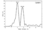
- FIG. 5 is a graph showing a cross section of the molybdenum disulfide particles shown in FIG. 6 is an extended X-ray absorption fine structure (EXAFS) profile of the molybdenum K absorption edge measured using the molybdenum disulfide particles obtained in Synthesis Example 1.
- EXAFS extended X-ray absorption fine structure
- the radioactive substance adsorbent according to this embodiment contains a metal sulfide, and is preferably composed of a metal sulfide.
- the radioactive substance adsorbent of this embodiment has selectivity for radioactive substances and exhibits high adsorption performance for radioactive substances.
- the metal sulfide preferably contains molybdenum disulfide particles as a main component, and is more preferably composed of molybdenum disulfide particles. It is considered that the high ability to adsorb radioactive substances is due to, for example, the small median diameter D50 of the molybdenum disulfide particles of 1000 nm or less.
- the selective adsorption performance of radioactive substances is considered to be due to, for example, the sulfur element in the metal sulfide having a property of being easily adsorbed to radioactive substances.
- the form of the radioactive substance adsorbent include metal sulfide particles, and molybdenum disulfide particles are preferred.
- the metal sulfide particles preferably contain molybdenum disulfide particles and more preferably consist of molybdenum disulfide particles.
- the radioactive substance of the present embodiment may contain a radioactive isotope, for example, it may contain a stable isotope and a radioactive isotope, or it may consist of only a radioactive isotope.
- the radioactive substance adsorbent of this embodiment is particularly excellent in adsorption performance for ruthenium.
- the excellent ruthenium adsorption performance is that the median diameter D50 of the molybdenum disulfide particles is as small as 1000 nm or less, the 3R crystal structure of molybdenum disulfide, and / or the affinity between ruthenium and sulfur is very high. This is thought to be caused by
- the radioactive material to be adsorbed by the molybdenum disulfide particles is preferably one or more selected from ruthenium and cobalt, more preferably ruthenium.
- the median diameter D50 of the molybdenum disulfide particles in the radioactive substance adsorbent of the present embodiment determined by the dynamic light scattering method is, for example, 10 nm or more and 1000 nm or less. is more preferable, and 400 nm or less is particularly preferable.
- the median diameter D50 of the molybdenum disulfide particles may be 10 nm or more, 20 nm or more, or 40 nm or more.
- the median diameter D50 of the molybdenum disulfide particles is determined, for example, by a dynamic light scattering particle size distribution analyzer (Microtrack Bell, Nanotrac Wave II) or a laser diffraction particle size distribution analyzer (SALD-7000 by Shimadzu Corporation). Measured using
- the molybdenum disulfide particles in the radioactive substance adsorbent of this embodiment preferably contain the 3R crystal structure of molybdenum disulfide. Inclusion of the 3R crystal structure increases the crystal edge portion of the molybdenum disulfide particles and increases the ion adsorption sites, which is considered to contribute to further improvement of the radioactive substance adsorption performance. Moreover, by containing the 3R crystal structure, the adsorption performance of ruthenium, among other radioactive substances, is remarkably improved. It is presumed that this is due to the specific surface area derived from the nanostructure of the molybdenum disulfide particles.
- the point that the molybdenum disulfide particles contain a metastable 3R crystal structure is a peak near 39.5 ° in a profile obtained from powder X-ray diffraction (XRD) using Cu-K ⁇ rays as an X-ray source.
- XRD powder X-ray diffraction
- the peaks near 49.5° are both synthetic peaks (broad peaks) of the 2H crystal structure and the 3R crystal structure.
- the molybdenum disulfide particles in the radioactive substance adsorbent of the present embodiment preferably contain 2H crystal structure and 3R crystal structure of molybdenum disulfide.
- Generally commercially available molybdenum disulfide particles include many particles with a particle size exceeding 1 ⁇ m, and are hexagonal solids, and as shown in FIG. .
- the molybdenum disulfide particles produced through the "method for producing molybdenum trioxide particles" and "method for producing molybdenum disulfide particles” described below contain a 2H crystal structure and a 3R crystal structure, and have a median diameter of D50 . can be easily adjusted from 10 nm to 1000 nm.
- the fact that the molybdenum disulfide particles have a 2H crystal structure and a 3R crystal structure can be confirmed using, for example, Rietveld analysis software (manufactured by PANalytical, High Score Plus) that can consider the crystallite size. .
- Rietveld analysis software manufactured by PANalytical, High Score Plus
- the entire XRD diffraction profile is simulated using a crystal structure model including the crystallite size, compared with the XRD diffraction profile obtained in the experiment, and compared with the diffraction profile obtained in the experiment.
- the crystallite size can be calculated in addition to the crystal structure type and its ratio calculated by the usual Rietveld analysis.
- extended Rietveld analysis the analysis method using the high score plus is referred to as "extended Rietveld analysis”.
- the peaks near 39.5 ° and the peaks near 49.5 ° Derived from the 2H crystal structure a peak near 32.5 °, a peak near 39.5 ° and a peak near 49.5 ° derived from the 3R crystal structure, a peak near 39.5 ° and 49.5 It is preferable that the half width of the peak near ° is 1° or more.
- the molybdenum disulfide particles may contain a crystal structure other than the 2H crystal structure and 3R crystal structure of molybdenum disulfide, such as a 1H crystal structure.
- the shape of the primary particles of the molybdenum disulfide particles in a two-dimensional image taken with a transmission electron microscope (TEM) is particulate, spherical, plate-like, needle-like, string-like, ribbon-like, or sheet-like. may be included, or a combination of these shapes may be included.
- the shape of the primary particles of the molybdenum disulfide particles is preferably disk-like, ribbon-like or sheet-like.
- the shape of the primary particles of the molybdenum disulfide particles preferably has a thickness in the range of 3 nm or more, and a size in the range of 5 nm or more, as measured by an atomic force microscope (AFM).
- the shape of the primary particles of the molybdenum disulfide particles preferably has a thickness in the range of 100 nm or less, and a size in the range of 50 nm or less, as measured by an atomic force microscope (AFM). It is more preferable to have, and it is particularly preferable to have a size in the range of 20 nm or less.
- the shape of the primary particles of the molybdenum disulfide particles may have a thickness in the range of 40 nm or less, measured by an atomic force microscope (AFM), and a size in the range of 30 nm or less.
- the shape of the primary particles of the molybdenum disulfide particles is disk-like, ribbon-like or sheet-like, the specific surface area of the molybdenum disulfide particles can be increased. Further, it is preferable that the molybdenum disulfide particles have a primary particle shape of a disk, a ribbon or a sheet, and have a thickness in the range of 3 to 100 nm.
- the disk-like, ribbon-like or sheet-like means a thin layer shape.
- the aspect ratio of the primary particles of molybdenum sulfide is preferably 1.2 to 1200 on the average of 50 particles, It is more preferably 2-800, even more preferably 5-400, and particularly preferably 10-200.
- the shape, length, width, and thickness of the primary particles of 50 molybdenum disulfide particles can be measured by observation with an atomic force microscope (AFM), and the aspect ratio can be calculated from the measurement results. It is possible.
- the shape of the primary particles of the molybdenum disulfide particles is not simply spherical, but disk-like, ribbon-like or sheet-like with a large aspect ratio, thereby increasing the contact area between the molybdenum disulfide particles and the radioactive substance. can be expected, and is thought to contribute to an increase in the amount of adsorption of radioactive substances.
- the specific surface area of the molybdenum disulfide particles in the radioactive substance adsorbent of the present embodiment as measured by the BET method is preferably 10 m 2 /g or more, more preferably 30 m 2 /g or more, and more preferably 40 m 2 /g. g or more is particularly preferred.
- the specific surface area of the molybdenum disulfide particles measured by the BET method may be 300 m 2 /g or less, or 200 m 2 /g or less.
- the radioactive substance adsorbent in which the molybdenum disulfide particles in the radioactive substance adsorbent of the present embodiment have a specific surface area of 10 m 2 /g or more as measured by the BET method can increase the contact area with the radioactive substance. It is considered that the adsorption performance of the
- the intensity I of the peak due to Mo—S and the ratio (I/II) of the peak intensity II due to Mo-Mo is preferably greater than 1.0, more preferably 1.1 or more, and particularly preferably 1.2 or more .
- the crystal structure of molybdenum disulfide is the 2H crystal structure or the 3R crystal structure
- the distance between Mo—S is almost the same due to the covalent bond, so the extended X-ray absorption fine structure (EXAFS) profile of the K absorption edge of molybdenum
- the peak intensity due to Mo—S is the same.
- the 2H crystal structure of molybdenum disulfide is hexagonal, the same hexagon is located directly below the hexagon of Mo atoms at 90°, so the distance between Mo-Mo becomes closer, and Mo-Mo The resulting peak intensity II becomes stronger.
- the hexagon exists not at 90° directly below the hexagon, but at a half offset, so that the distance between Mo-Mo becomes longer, and Mo The peak intensity II due to -Mo is weakened. While the pure 2H crystal structure of molybdenum disulfide has a lower ratio (I/II), the ratio (I/II) increases as the 3R crystal structure is included.
- the hexagons of Mo atoms in each of the three layers are offset from each other by half a hexagon, so each layer It can be expected that the interaction between them will be small and that radioactive substances will be easily adsorbed.
- the conversion rate R C of molybdenum disulfide particles to MoS 2 in the radioactive substance adsorbent of this embodiment is preferably 70% or more because the presence of molybdenum trioxide is considered to have an adverse effect on the radioactive substance adsorption performance. , is more preferably 80% or more, and particularly preferably 90% or more.
- the molybdenum disulfide particles in the radioactive substance adsorbent of the present embodiment can show a conversion rate R C of nearly 100% to MoS 2 , so that other molybdenum disulfide materials that can contain molybdenum trioxide as a by-product or The radioactive substance adsorption performance can be superior to that of the precursor.
- the conversion rate R C of the molybdenum disulfide particles to MoS 2 in the radioactive substance adsorbent of the present embodiment is obtained from the profile data obtained by X-ray diffraction (XRD) measurement of the molybdenum disulfide particles, from the RIR (see below) intensity ratio) method.
- XRD X-ray diffraction
- the radioactive substance adsorbent of this embodiment can adsorb and remove radioactive substance ions, radioactive substances, or radioactive substance compounds contained in a radioactive substance-containing solution, for example, a radioactive substance-containing aqueous solution. Further, the radioactive substance adsorbent of this embodiment can adsorb and remove radioactive substances or radioactive substance compounds contained in the radioactive substance-containing gas.
- the method for producing the radioactive substance adsorbent according to this embodiment is not particularly limited, but for example, it can be produced by heating a metal oxide in the presence of a sulfur source.
- the radioactive substance adsorbent of the present embodiment is not limited to those obtained by the above-described production method, and may be commercially available metal sulfides, such as commercially available molybdenum disulfide particles, as long as the adsorption performance of the present invention can be expressed. good.
- Molybdenum disulfide particles in the radioactive substance adsorbent of the present embodiment can be produced, for example, by heating molybdenum trioxide particles at a temperature of 200 to 1000° C. in the presence of a sulfur source.
- the average particle size of the primary particles of the molybdenum trioxide particles is preferably 2 nm or more and 1000 nm or less.
- the average particle size of the primary particles of the molybdenum trioxide particles is the minimum size of the molybdenum trioxide particles that constitutes aggregates on a two-dimensional image obtained by photographing the molybdenum trioxide particles with a scanning electron microscope (SEM) or a transmission electron microscope (TEM).
- SEM scanning electron microscope
- TEM transmission electron microscope
- the average particle size of the primary particles of the molybdenum trioxide particles is preferably 1 ⁇ m or less. From the point of reactivity with sulfur, it is more preferably 600 nm or less, even more preferably 400 nm or less, and particularly preferably 200 nm or less.
- the average particle diameter of the primary particles of the molybdenum trioxide particles may be 2 nm or more, 5 nm or more, or 10 nm or more.
- the molybdenum trioxide particles used for producing the molybdenum disulfide particles in the radioactive substance adsorbent of the present embodiment are preferably composed of an aggregate of primary particles containing the ⁇ crystal structure of molybdenum trioxide.
- the molybdenum trioxide particles have better reactivity with sulfur than conventional molybdenum trioxide particles consisting of only ⁇ crystals as a crystal structure, and contain the ⁇ crystal structure of molybdenum trioxide.
- the conversion rate R C to MoS 2 can be increased.
- the ⁇ crystal structure of molybdenum trioxide is assigned to the (011) plane of the ⁇ crystal of MoO3 in the profile obtained from X-ray powder diffraction (XRD) using Cu-K ⁇ radiation as the X-ray source, (2 ⁇ : It can be confirmed by the presence of a peak near 23.01°, No. 86426 (Inorganic Crystal Structure Database, ICSD)).
- the ⁇ crystal structure of molybdenum trioxide can be confirmed by the presence of the peak of the (021) plane of the ⁇ crystal of MoO3 (2 ⁇ : around 27.32°, No. 166363 (Inorganic Crystal Structure Database, ICSD)). can.
- the molybdenum trioxide particles belong to the (011) plane of the ⁇ crystal of MoO 3 (2 ⁇ : 23.01 ° near No. 86426 (Inorganic Crystal Structure Database (ICSD))) peak intensity attributed to the (021) plane of the ⁇ crystal of MoO 3 (2 ⁇ : near 27.32 °, No. 166363 (Inorganic Crystal Structure Database (ICSD)))
- the ratio to the peak intensity ( ⁇ (011)/ ⁇ (021)) is preferably 0.1 or more.
- the peak intensity attributed to the (011) plane of the ⁇ crystal of MoO 3 and the peak intensity attributed to the (021) plane of the ⁇ crystal of MoO 3 read the maximum intensity of the peak, respectively, and the ratio ( ⁇ (011 )/ ⁇ (021)).
- the ratio ( ⁇ (011)/ ⁇ (021)) is preferably 0.1 to 10.0, more preferably 0.2 to 10.0. .4 to 10.0 are particularly preferred.
- the ⁇ crystal structure of molybdenum trioxide can also be confirmed by the presence of peaks at wavenumbers 773, 848 cm ⁇ 1 and 905 cm ⁇ 1 in the Raman spectrum obtained from Raman spectroscopy.
- the ⁇ crystal structure of molybdenum trioxide can be confirmed by the presence of peaks at wavenumbers of 663, 816 cm ⁇ 1 and 991 cm ⁇ 1 .
- the average particle diameter of the primary particles of the molybdenum trioxide particles may be 5 nm or more and 2000 nm or less.
- sulfur sources include sulfur and hydrogen sulfide, and these may be used alone or in combination.
- the method for producing molybdenum disulfide particles includes heating molybdenum trioxide particles, which are aggregates of primary particles containing a ⁇ crystal structure of molybdenum trioxide, at a temperature of 100 to 800° C. in the absence of a sulfur source, and then It may include heating at a temperature of 200-1000° C. in the presence of a sulfur source.
- the heating time in the presence of the sulfur source may be a time for the sulfurization reaction to proceed sufficiently, and may be 1 to 20 hours, 2 to 15 hours, or 3 to 10 hours.
- the charging ratio of the amount of S in the sulfur source to the amount of MoO 3 in the molybdenum trioxide particles is such that the sulfurization reaction proceeds sufficiently.
- the amount of S in the sulfur source is preferably 450 mol% or more, preferably 600 mol% or more, and preferably 700 mol% or more with respect to 100 mol% of MoO 3 in the molybdenum trioxide particles. is preferred.
- the amount of S in the sulfur source may be 3000 mol% or less, 2000 mol% or less, or 1500 mol% or less with respect to 100 mol% of MoO 3 in the molybdenum trioxide particles. good too.
- the heating temperature in the presence of the sulfur source may be a temperature at which the sulfurization reaction sufficiently proceeds, preferably 320° C. or higher, more preferably 340° C. or higher. , 360° C. or higher is particularly preferred. It may be 320 to 1000°C, 340 to 800°C, or 360 to 600°C.
- the molybdenum trioxide particles preferably have a MoO3 content of 99.5% or more as measured by X-ray fluorescence (XRF). It is possible to increase the conversion rate R 2 to MoS 2 , and obtain molybdenum disulfide of high purity and good storage stability without the risk of generating sulfides derived from impurities.
- XRF X-ray fluorescence
- the molybdenum trioxide particles preferably have a specific surface area of 10 m 2 /g or more and 100 m 2 /g or less as measured by the BET method.
- the specific surface area is preferably 10 m 2 /g, preferably 20 m 2 /g, and more preferably 30 m 2 /g because reactivity with sulfur is improved. is preferred.
- the particle size is preferably 100 m 2 /g, may be 90 m 2 /g, or may be 80 m 2 /g, because production is facilitated.
- the molybdenum trioxide particles have a radial distribution function obtained from the extended X-ray absorption fine structure (EXAFS) profile of the K absorption edge of molybdenum, the intensity I of the peak due to Mo-O and the peak due to Mo-Mo
- the ratio (I/II) to intensity II is preferably greater than 1.1.
- the ratio (I/II) is considered to be an indication that the ⁇ crystal structure of MoO3 is obtained in the molybdenum trioxide particles, and the larger the ratio (I/II), the more reactive with sulfur Excellent for
- the ratio (I/II) is preferably 1.1 to 5.0, may be 1.2 to 4.0, and may be 1.2 to 3.0. There may be.
- the molybdenum trioxide particles can be produced by vaporizing a molybdenum oxide precursor compound to form a molybdenum trioxide vapor and cooling the molybdenum trioxide vapor.
- the method for producing the molybdenum trioxide particles includes firing a raw material mixture containing a molybdenum oxide precursor compound and a metal compound other than the molybdenum oxide precursor compound, vaporizing the molybdenum oxide precursor compound, and molybdenum trioxide particles. It is preferable that the ratio of the metal compound to 100% by mass of the raw material mixture is 70% by mass or less in terms of oxide, including the formation of vapor.
- the method for producing molybdenum trioxide particles can be suitably carried out using the production apparatus 1 shown in FIG.
- FIG. 1 is a schematic diagram of an example of an apparatus used for producing the molybdenum trioxide particles that are the raw material of the molybdenum disulfide particles in this embodiment.
- a manufacturing apparatus 1 includes a firing furnace 2 for firing a molybdenum trioxide precursor compound or the raw material mixture and vaporizing the molybdenum trioxide precursor compound; It has a cross-shaped cooling pipe 3 for pulverizing molybdenum oxide vapor, and a collector 4 as a collecting means for collecting molybdenum trioxide particles pulverized in the cooling pipe 3 .
- the firing furnace 2 and the cooling pipe 3 are connected through an exhaust port 5 .
- the cooling pipe 3 is provided with an opening adjusting damper 6 for an outside air intake (not shown) at the left end, and an observation window 7 at the upper end.
- the collection machine 4 is connected to an exhaust device 8 as a first air blowing means. When the exhaust device 8 exhausts the air, the collector 4 and the cooling pipe 3 are sucked, and outside air is blown to the cooling pipe 3 from the opening adjustment damper 6 of the cooling pipe 3 . That is, the cooling pipe 3 is passively blown with air by the exhaust device 8 having a suction function.
- the manufacturing apparatus 1 may have an external cooling device 9, which makes it possible to arbitrarily control the cooling conditions of the molybdenum trioxide vapor generated from the kiln 2.
- Air is taken in from the outside air intake port by the opening adjustment damper 6, and the molybdenum trioxide vapor vaporized in the firing furnace 2 is cooled in an air atmosphere to form molybdenum trioxide particles, so that the ratio (I / II) can be greater than 1.1, and the ⁇ crystal structure of MoO3 is likely to be obtained in the molybdenum trioxide particles.
- the molybdenum trioxide precursor compound is not particularly limited as long as it forms a molybdenum trioxide vapor when fired, and includes metallic molybdenum, molybdenum trioxide, molybdenum dioxide, molybdenum sulfide, ammonium molybdate, and phosphomolybdic acid.
- molybdenum trioxide precursor compounds may be used alone or in combination of two or more.
- the form of the molybdenum trioxide precursor compound is not particularly limited, and may be, for example, powder such as molybdenum trioxide, or liquid such as an aqueous ammonium molybdate solution. Preferably, it is in the form of powder, which is easy to handle and energy efficient.
- molybdenum trioxide precursor compound it is preferable to use commercially available ⁇ -crystalline molybdenum trioxide. Further, when ammonium molybdate is used as the molybdenum oxide precursor compound, it is converted to thermodynamically stable molybdenum trioxide by firing, so the molybdenum oxide precursor compound to be vaporized is the molybdenum trioxide. .
- Molybdenum trioxide vapor can also be formed by firing a raw material mixture containing a molybdenum oxide precursor compound and a metal compound other than the molybdenum oxide precursor compound.
- the molybdenum oxide precursor compound preferably contains molybdenum trioxide in terms of ease of control of the purity of the obtained molybdenum trioxide particles, the average particle size of the primary particles, and the crystal structure.
- a molybdenum oxide precursor compound and a metal compound other than the molybdenum oxide precursor compound may sometimes form an intermediate. It can be vaporized in the form
- the content of the molybdenum oxide precursor compound with respect to 100% by mass of the raw material mixture is 40 to 100 mass%. %, may be 45 to 100% by mass, or may be 50 to 100% by mass.
- the firing temperature varies depending on the molybdenum oxide precursor compound, the metal compound, and the desired molybdenum trioxide particles used, it is usually preferable to set the temperature at which the intermediates can be decomposed.
- the temperature is preferably 500 to 1500 ° C. It is more preferably 600 to 1550°C, even more preferably 700 to 1600°C.
- the firing time is also not particularly limited, and can be, for example, 1 min to 30 hours, 10 min to 25 hours, or 100 min to 20 hours.
- the rate of temperature increase varies depending on the properties of the molybdenum oxide precursor compound used, the metal compound, and the desired molybdenum trioxide particles. It is preferably 1° C./min or more and 50° C./min or less, more preferably 2° C./min or more and 10° C./min or less.
- the molybdenum trioxide vapor is then cooled and granulated. Cooling of the molybdenum trioxide vapor is performed by lowering the temperature of the cooling pipe.
- the cooling means includes cooling by blowing gas into the cooling pipe, cooling by a cooling mechanism provided in the cooling pipe, and cooling by an external cooling device, as described above.
- Cooling of the molybdenum trioxide vapor is preferably carried out in an air atmosphere.
- the ratio (I/II) can be made larger than 1.1, and in the molybdenum trioxide particles, ⁇ crystals of MoO 3 Easy to obtain structure.
- the cooling temperature (the temperature of the cooling pipe) is not particularly limited, but is preferably -100 to 600°C, more preferably -50 to 400°C.
- the cooling rate of the molybdenum trioxide vapor is not particularly limited, it is preferably 100°C/s or more and 100000°C/s or less, more preferably 1000°C/s or more and 50000°C/s or less. There is a tendency that molybdenum trioxide particles having a smaller particle size and a larger specific surface area can be obtained as the cooling rate of the molybdenum trioxide vapor increases.
- the temperature of the blown gas is preferably -100 to 300°C, more preferably -50 to 100°C.
- the particles obtained by cooling the molybdenum trioxide vapor are transported to and collected by the collector.
- the particles obtained by cooling the molybdenum trioxide vapor may be fired again at a temperature of 100 to 320°C.
- the molybdenum trioxide particles obtained by the method for producing molybdenum trioxide particles may be fired again at a temperature of 100 to 320°C.
- the firing temperature for the second firing may be 120 to 280.degree. C. or 140 to 240.degree.
- the firing time for the second firing can be, for example, 1 min to 4 hours, 10 min to 5 hours, or 100 min to 6 hours.
- part of the ⁇ crystal structure of molybdenum trioxide disappears, and when fired at a temperature of 350 ° C. or higher for 4 hours, the ⁇ crystal structure in the molybdenum trioxide particles disappears. , the ratio ( ⁇ (011)/ ⁇ (021)) becomes 0 and the reactivity with sulfur is impaired.
- Molybdenum disulfide particles in the radioactive substance adsorbent of this embodiment can be produced by the method for producing the radioactive substance adsorbent.
- molybdenum trioxide particles suitable for producing molybdenum disulfide particles in the radioactive substance adsorbent of the present embodiment can be produced by the method for producing molybdenum trioxide particles.
- R C (%) ( IA / KA )/( ⁇ (IB/ KB )) ⁇ 100 (1)
- the RIR values used were the values described in the Inorganic Crystal Structure Database (ICSD), and the integrated powder X-ray analysis software (PDXL) (manufactured by Rigaku Corporation) was used for the analysis.
- EXAFS Extra X-ray absorption fine structure
- the solution is prepared in the same manner, and particles with a particle size in the range of 0.015 to 500 ⁇ m are measured using a laser diffraction particle size distribution analyzer (SALD-7000, manufactured by Shimadzu Corporation). The size distribution was measured and the median diameter D50 was calculated.
- SALD-7000 laser diffraction particle size distribution analyzer
- Molybdenum disulfide particles were measured with an atomic force microscope (AFM) (Oxford Cypher-ES) to observe the particle shape.
- Example 1 As molybdenum disulfide particles used in Example 1, the result of the X-ray diffraction pattern of a commercially available molybdenum disulfide reagent (manufactured by Kanto Kagaku Co., Ltd.) is shown in FIG. 2 together with the diffraction pattern of molybdenum disulfide with a 2H crystal structure. .
- the molybdenum disulfide reagent of Example 1 was found to be molybdenum disulfide with a 2H crystal structure of 99% or more.
- the half widths of the peak near 39.5° and the peak near 49.5° were 0.23° and 0.22°, respectively.
- the specific surface area (SA), the intensity of the peak due to Mo—S obtained from the measurement of the extended X-ray absorption fine structure (EXAFS) of the K absorption edge of molybdenum, I and the peak intensity II due to Mo—Mo (I/II) was 1.2.
- the specific surface area of the molybdenum disulfide particles used in Example 1 was measured by the BET method and found to be 5.6 m 2 /g. Further, the particle size distribution of the molybdenum disulfide particles used in Example 1 was measured by a dynamic light scattering particle size distribution analyzer, and the median diameter D50 was determined to be 13340 nm.
- ⁇ Synthesis Example 1> (Production of molybdenum trioxide particles) 1 kg of transitional aluminum oxide (manufactured by Wako Pure Chemical Industries, Ltd., activated alumina, average particle size 45 ⁇ m) and 1 kg of molybdenum trioxide (manufactured by Taiyo Koko Co., Ltd.) are mixed, then charged into a sachet, and the production apparatus shown in FIG. 1 was fired at a temperature of 1100° C. for 10 hours in the firing furnace 2. During firing, outside air (blowing speed: 50 L/min, outside air temperature: 25° C.) was introduced from the side and bottom surfaces of the firing furnace 2 .
- outside air blow speed: 50 L/min, outside air temperature: 25° C.
- Molybdenum trioxide was evaporated in the calcining furnace 2, cooled in the vicinity of the collector 4, and precipitated as particles.
- a RHK simulator manufactured by Noritake Co., Ltd.
- VF-5N dust collector manufactured by Amano
- the specific surface area of the molybdenum disulfide particles of Synthesis Example 1 was measured by the BET method and found to be 67.8 m 2 /g.
- the particle size distribution of the molybdenum disulfide particles of Synthesis Example 1 was measured with a dynamic light scattering particle size distribution analyzer, and the median diameter D50 was determined to be 170 nm.
- FIG. 4 is an AFM image obtained by the measurement, showing the upper surface of the molybdenum disulfide particles.
- FIG. 5 is a graph showing a cross section of the molybdenum disulfide particles shown in FIG.
- the thickness (height) was obtained from this cross-sectional view, it was 16 nm. Therefore, the aspect ratio (length (longitudinal)/thickness (height)) of the primary particles of the molybdenum disulfide particles was 11.25.
- Table 1 shows representative examples of AFM measurement results of molybdenum disulfide particles.
- molybdenum disulfide particles (1) are molybdenum disulfide particles shown in FIG.
- Molybdenum disulfide particles (2) are the particles with the longest length among the measured molybdenum disulfide particles
- Molybdenum disulfide particles (3) are the particles with the shortest length.
- Molybdenum disulfide particles (4) are relatively thick particles
- “Molybdenum disulfide particles (5)” are the thinnest particles.
- Molybdenum disulfide particles (6) are particles with the largest aspect ratio.
- Molybdenum disulfide particles (7) are particles having the largest thickness and the smallest aspect ratio.
- the extended X-ray absorption fine structure (EXAFS) of the molybdenum disulfide particles of Synthesis Example 1 was measured.
- the extended X-ray absorption fine structure (EXAFS) profile of the K-edge of molybdenum is shown in FIG. In the radial distribution function obtained from this profile, the ratio (I/II) between the peak intensity I due to Mo--S and the peak intensity II due to Mo--Mo was 1.2.
- Example 1 [Radioactive substance (ruthenium) adsorption evaluation] ⁇ Example 1> A 1000 ppm ruthenium standard solution (manufactured by ACROS ORGANICS) was diluted with ion-exchanged water, and an aqueous sodium hydroxide solution was used to prepare a solution to be adsorbed so that the pH was 3.5 and the initial ruthenium concentration was about 1000 ppb.
- the sample solution was filtered with a 0.2 ⁇ m syringe filter, and the concentration of ruthenium remaining in the sample solution was quantified with an ICP emission spectrometer (ICP-OES, Optima8300, manufactured by PerkinElmer). Also, using the residual ruthenium concentration in the sample solution after 24 hours and the input amount of molybdenum disulfide powder, the amount of ruthenium adsorbed per 1 g of adsorbent for 24 hours (g/g) was calculated from the following formula.
- Amount of ruthenium adsorbed for 24 hours (initial ruthenium concentration ⁇ ruthenium concentration after 24 hours) ⁇ liquid volume/amount of molybdenum disulfide powder charged
- Adsorption rate (initial ruthenium concentration - ruthenium concentration after 24 hours) / initial ruthenium concentration x 100
- Example 2 In the same manner as in Example 1, except that the molybdenum disulfide powder obtained in Synthesis Example 1 was used instead of the commercially available molybdenum disulfide powder, the ruthenium residual concentration in the sample solution after 24 hours and the adsorbent The amount of ruthenium adsorbed per 1 g for 24 hours was calculated.
- Example 2 From the results in Table 2, in Example 1, when 30 mg of commercially available molybdenum disulfide powder was used as the adsorbent, the ruthenium concentration in the solution after 24 hours was 80 ppb, the ruthenium adsorption amount was 0.69 g / g, and the ruthenium adsorption The ruthenium adsorption rate was 89.6%, indicating that the ruthenium adsorption rate was high and good adsorption performance was exhibited.
- Example 2 when 30 mg of the molybdenum disulfide powder of Synthesis Example 1 was used, the ruthenium concentration in the solution after 24 hours was 67 ppb, the ruthenium adsorption amount was 0.70 g/g, and the ruthenium adsorption rate was 91.3%. , and it was found that the ruthenium adsorption rate was higher than that of Example 1 and that better adsorption performance was exhibited.
- Comparative Example 1 when 30 mg of carbon was used as the adsorbent, the ruthenium concentration in the solution after 24 hours was 271 ppb, the ruthenium adsorption amount was 0.50 g/g, and the ruthenium adsorption rate was 64.7%. As compared with Examples 3 and 4 in which molybdenum disulfide powder was used as an adsorbent, the ruthenium adsorption rate was low and the adsorption performance was inferior.
- the radioactive substance adsorbent of the present invention has a high adsorption performance for radioactive substances, it can be suitably used as a radioactive substance adsorption material when adsorbing radioactive substances from radioactive waste liquids from nuclear facilities and the like. Among them, it can be particularly suitably used as a material for adsorbing ruthenium from radioactive waste liquids containing ruthenium at high to low concentrations because of its remarkably excellent adsorption performance for ruthenium. In addition, since the radioactive substance adsorption method of the present invention can easily adsorb radioactive substances, it is extremely useful as a method for adsorbing radioactive substances from contaminated water or the like generated from nuclear facilities or the like.
Landscapes
- Chemical & Material Sciences (AREA)
- Analytical Chemistry (AREA)
- Organic Chemistry (AREA)
- Chemical Kinetics & Catalysis (AREA)
- Physics & Mathematics (AREA)
- Engineering & Computer Science (AREA)
- General Engineering & Computer Science (AREA)
- High Energy & Nuclear Physics (AREA)
- Inorganic Chemistry (AREA)
- Inorganic Compounds Of Heavy Metals (AREA)
Abstract
放射性物質の初期濃度が低い場合であっても高い吸着率で優れた吸着性能を発揮することができる放射性物質吸着剤を提供する。 本発明の放射性物質吸着剤は、金属硫化物を含有する。前記金属硫化物は、例えば二硫化モリブデン粒子で構成されている。
Description
本発明は、放射性物質吸着剤に関する。
本出願は、2021年3月24日に、日本に出願された特願2021-050487に基づき優先権を主張し、その内容をここに援用する。
本出願は、2021年3月24日に、日本に出願された特願2021-050487に基づき優先権を主張し、その内容をここに援用する。
原子力設備では、例えば燃料デブリの冷却水と原子炉建屋、タービン建屋等に流入した地下水とが混ざり合うことで生じた汚染水を他核種除去装置(ALPS)で処理し、処理水としてタンクに貯蔵されている。上記汚染水や処理水のような放射性廃液において、特に主要七核種(Cs-134、Cs-137、Sr-90、I-129、Ru-106、Co-60、Sb-125)の放射性元素の存在が問題とされており、これを浄化する際に、無機ないし有機イオン交換体を用いて浄化する方法が知られている。イオン交換体を放射性物質の吸着材として用いて放射性廃液を浄化する場合は、イオン交換という原理上、その吸着能力には限界がある。また、その吸着効率を向上するために、短時間で低濃度まで放射性物質を吸着する性能が求められる。
従来、例えば有機イオン交換体として、N-ビニルカルボン酸アミドと架橋性単量体を塩水中で分散剤存在下、懸濁重合しポリビニルカルボン酸アミド架橋重合体粒子を得た後に、該架橋重合体を加水分解することにより得られたポリビニルアミン架橋重合体粒子をキレート樹脂として用いる方法が開示されている(特許文献1)。
また、無機イオン交換体として、酸化マンガンを主成分とし、さらに遷移金属元素として銅又は無機バインダーとして酸化アルミニウムを含むルテニウム吸着剤が開示されている。本方法では、マンガン化合物の構造欠陥を利用してルテニウム除去率を向上させていると考えられる(特許文献2)。
また近年、無機、有機イオン交換体以外の吸着剤として、シアニディウム目の紅藻の細胞の乾燥物、シアニディウム目の紅藻の細胞表層由来物の乾燥物、又は前記細胞の乾燥物もしくは前記細胞表層由来物の乾燥物を模した人工物を含む金属回収剤が提案されている(特許文献3)。
しかしながら、特許文献1では、初期濃度約4.5ppmのルテニウム溶解液500mLに10mgのキレート樹脂を投入して撹拌した場合、24時間経過後のルテニウム溶解液の濃度が100ppb未満となっているが、ルテニウムをはじめとする放射性物質の初期濃度が1ppm以下などの低濃度であっても、100ppb以下のより低い濃度となるまで放射性物質を吸着できる吸着剤が求められている。また、有機イオン交換体であるキレート樹脂は、種々の材料を用いて重合、ろ過、加水分解など様々な工程経て製造されるため煩雑な作業を要し、高コストとなることが懸念される。
特許文献2では、実施例において吸着後のルテニウムの具体的な濃度が示されておらず、また、250mlのポリ容器に50mLの試験液を入れ、180回/分で振とうして吸着させているが、激しい試験条件であり、実施される際の条件、例えば通水条件での吸着能力に懸念がある。
また、特許文献3では、初期濃度10ppmのルテニウム溶解液からルテニウムを吸着したときの吸着率は50%程度にとどまり、未だ改善の余地がある。
特許文献2では、実施例において吸着後のルテニウムの具体的な濃度が示されておらず、また、250mlのポリ容器に50mLの試験液を入れ、180回/分で振とうして吸着させているが、激しい試験条件であり、実施される際の条件、例えば通水条件での吸着能力に懸念がある。
また、特許文献3では、初期濃度10ppmのルテニウム溶解液からルテニウムを吸着したときの吸着率は50%程度にとどまり、未だ改善の余地がある。
本発明は、放射性物質の初期濃度が低い場合であっても高い吸着率で優れた吸着性能を発揮することができ、且つ放射性物質を容易に吸着することができる放射性物質吸着剤を提供することを目的とする。
本発明者らは、鋭意研究を重ねた結果、金属硫化物を放射性物質吸着剤、特に二硫化モリブデン粒子を放射性物質吸着剤として用いると、金属硫化物の放射性物質に対する選択性により、高い吸着性能を実現できることを見出した。なかでも、二硫化モリブデン粒子をルテニウムの吸着剤として用いると、二硫化モリブデン粒子のルテニウムに対する選択性が高く、初期濃度が低いルテニウム含有溶液からルテニウムを吸着する際の吸着率が従来のルテニウム吸着剤よりも高く、吸着性能を向上できることを見出した。
また、本出願人が保有する技術「nmサイズの三酸化モリブデン微粒子」を原料として二硫化モリブデン粒子を製造すると、粒子含有樹脂組成物の鉱山品の粉砕や汎用三酸化モリブデン(μmスケール)からの合成では達成困難な、板状構造をもち且つ単位重量当たりの表面積が大きいnmサイズの二硫化モリブデン粒子が得られる。よってこの二硫化モリブデン粒子を放射性物質吸着剤、特にルテニウム吸着剤として用いると、二硫化モリブデン粒子の大きい比表面積及びルテニウムと硫黄との親和性により、放射性物質を良好に吸着できることを見出した。
すなわち、本発明は以下の構成を提供する。
[1]金属硫化物を含有する、放射性物質吸着剤。
[1]金属硫化物を含有する、放射性物質吸着剤。
[2]前記金属硫化物が二硫化モリブデン粒子で構成される、上記[1]に記載の放射性物質吸着剤。
[3]動的光散乱法により求められる前記二硫化モリブデン粒子のメディアン径D50が10nm以上1000nm以下である、上記[2]に記載の放射性物質吸着剤。
[4]前記二硫化モリブデン粒子の一次粒子の形状が、円盤状、リボン状またはシート状であり、厚さが、3~100nmの範囲である、上記[2]又は[3]に記載の放射性物質吸着剤。
[5]BET法で測定される、前記二硫化モリブデン粒子の比表面積が10m2/g以上である、上記[2]~[4]のいずれかに記載の放射性物質吸着剤。
[6]前記二硫化モリブデン粒子の、モリブデンのK吸収端の広域X線吸収微細構造(EXAFS)プロファイルから得られる動径分布関数において、Mo-Sに起因するピークの強度IとMo-Moに起因するピーク強度IIとの比(I/II)が、1.0より大きい、上記[2]~[5]のいずれかに記載の放射性物質吸着剤。
[7]前記二硫化モリブデン粒子が、二硫化モリブデンの2H結晶構造及び3R結晶構造を有し、
前記二硫化モリブデン粒子の、X線源としてCu-Kα線を用いた粉末X線回折(XRD)から得られるプロファイルにおいて、39.5°付近のピーク及び49.5°付近のピークが前記2H結晶構造に由来し、32.5°付近のピーク、39.5°付近のピーク及び49.5°付近のピークが前記3R結晶構造に由来し、
39.5°付近のピーク及び49.5°付近のピークの半値幅が1°以上である、上記[2]~[6]のいずれかに記載の放射性物質吸着剤。
前記二硫化モリブデン粒子の、X線源としてCu-Kα線を用いた粉末X線回折(XRD)から得られるプロファイルにおいて、39.5°付近のピーク及び49.5°付近のピークが前記2H結晶構造に由来し、32.5°付近のピーク、39.5°付近のピーク及び49.5°付近のピークが前記3R結晶構造に由来し、
39.5°付近のピーク及び49.5°付近のピークの半値幅が1°以上である、上記[2]~[6]のいずれかに記載の放射性物質吸着剤。
[8]前記二硫化モリブデン粒子に吸着される放射性物質が、ルテニウムである、上記[2]~[7]のいずれかに記載の放射性物質吸着剤。
本発明によれば、放射性物質の初期濃度が低い場合であっても高い吸着率で優れた吸着性能を発揮することができる。
以下、本発明の実施形態を図面を参照しながら詳細に説明する。
<放射性物質吸着剤>
本実施形態に係る放射性物質吸着剤は、金属硫化物を含有しており、好ましくは金属硫化物で構成される。本実施形態の放射性物質吸着剤は、放射性物質に対する選択性を有し、放射性物質の高い吸着性能を発揮する。金属硫化物は、二硫化モリブデン粒子を主成分とするのが好ましく、二硫化モリブデン粒子で構成されるのがより好ましい。放射性物質の吸着性能が高い点は、例えば前記二硫化モリブデン粒子の前記メディアン径D50が1000nm以下と小さいことに起因すると考えられる。放射性物質の上記選択的な吸着性能は、例えば金属硫化物中の硫黄元素が放射性物質と吸着しやすい性質を有することに起因すると考えられる。放射性物質吸着剤の形態としては、例えば金属硫化物粒子が挙げられ、二硫化モリブデン粒子が好ましい。金属硫化粒子は、二硫化モリブデン粒子を含有するのが好ましく、二硫化モリブデン粒子で構成されるのがより好ましい。
本実施形態に係る放射性物質吸着剤は、金属硫化物を含有しており、好ましくは金属硫化物で構成される。本実施形態の放射性物質吸着剤は、放射性物質に対する選択性を有し、放射性物質の高い吸着性能を発揮する。金属硫化物は、二硫化モリブデン粒子を主成分とするのが好ましく、二硫化モリブデン粒子で構成されるのがより好ましい。放射性物質の吸着性能が高い点は、例えば前記二硫化モリブデン粒子の前記メディアン径D50が1000nm以下と小さいことに起因すると考えられる。放射性物質の上記選択的な吸着性能は、例えば金属硫化物中の硫黄元素が放射性物質と吸着しやすい性質を有することに起因すると考えられる。放射性物質吸着剤の形態としては、例えば金属硫化物粒子が挙げられ、二硫化モリブデン粒子が好ましい。金属硫化粒子は、二硫化モリブデン粒子を含有するのが好ましく、二硫化モリブデン粒子で構成されるのがより好ましい。
本実施形態の放射性物質吸着剤が吸着できる放射性物質としては、例えばルテニウム(Ru)、コバルト(Co)、アンチモン(Sb)等の放射性物質が挙げられる。本実施形態の放射性物質は、放射性同位体を含むものであればよく、例えば安定同位体と放射性同位体を含むものであってもよいし、放射性同位体のみからなるものであってもよい。本実施形態の放射性物質吸着剤は、特にルテニウムの吸着性能に優れる。ルテニウムの吸着性能に優れる点は、前記二硫化モリブデン粒子の前記メディアン径D50が1000nm以下と小さいこと、二硫化モリブデンの3R結晶構造、及び/又は、ルテニウムと硫黄の親和性が非常に高いことに起因すると考えられる。
放射性物質吸着剤として二硫化モリブデン粒子を用いる場合には、二硫化モリブデン粒子に吸着される放射性物質としては、ルテニウム及びコバルトから選択される1種又は複数種が好ましく、ルテニウムがより好ましい。
放射性物質吸着剤として二硫化モリブデン粒子を用いる場合には、二硫化モリブデン粒子に吸着される放射性物質としては、ルテニウム及びコバルトから選択される1種又は複数種が好ましく、ルテニウムがより好ましい。
本実施形態の放射性物質吸着剤における二硫化モリブデン粒子の、動的光散乱法により求められるメディアン径D50は例えば10nm以上1000nm以下であり、前記の効果の点から、600nm以下が好ましく、500nm以下がより好ましく、400nm以下が特に好ましい。前記二硫化モリブデン粒子のメディアン径D50は10nm以上であってもよく、20nm以上であってもよく、40nm以上であってもよい。二硫化モリブデン粒子のメディアン径D50は、例えば動的光散乱式粒子径分布測定装置(マイクロトラックベル社製、Nanotrac WaveII)やレーザ回折式粒度分布測定装置(島津製作所社製 SALD-7000)等を用いて測定される。
本実施形態の放射性物質吸着剤における二硫化モリブデン粒子は、二硫化モリブデンの3R結晶構造を含むことが好ましい。3R結晶構造を含むことにより、二硫化モリブデン粒子の結晶のエッジ部分が増加し、イオン吸着サイトが増加することが、放射性物質の吸着性能の更なる向上に寄与すると考えられる。また、3R結晶構造を含むことにより、放射性物質のうち、特にルテニウムの吸着性能が格段に向上する。二硫化モリブデン粒子のナノ構造に由来する比表面積が起因していると推測される。
前記二硫化モリブデン粒子が、準安定構造の3R結晶構造を含む点は、X線源としてCu-Kα線を用いた粉末X線回折(XRD)から得られるプロファイルにおいて、39.5°付近のピーク、及び、49.5°付近のピークが共に2H結晶構造及び3R結晶構造の合成ピーク(ブロードピーク)からなることで区別することができる。
さらに、本実施形態の放射性物質吸着剤における二硫化モリブデン粒子は、二硫化モリブデンの2H結晶構造及び3R結晶構造を含むことが好ましい。一般に市販されている二硫化モリブデン粒子は、粒径が1μmを超える大きさのものを多く含み、また、六方晶固体であり、図2に示されるように、結晶構造としてほぼ2H結晶構造を有する。これに対して、後述する「三酸化モリブデン粒子の製造方法」及び「二硫化モリブデン粒子の製造方法」を経て製造する二硫化モリブデン粒子は、2H結晶構造及び3R結晶構造を含み、メディアン径D50を10nm以上1000nm以下に、容易に調整可能である。
二硫化モリブデン粒子が2H結晶構造及び3R結晶構造を有していることは、例えば結晶子サイズを考慮できるリートベルト解析ソフト(パナリティカル社製、ハイスコアプラス)を使用して確認することができる。このリートベルト解析ソフトでは、結晶子サイズを含めた結晶構造モデルを用いてXRDの回折プロファイル全体をシミュレートして、実験で得られるXRDの回折プロファイルと比較し、実験で得られた回折プロファイルと計算で得られた回折プロファイルの残差が最小になるように結晶構造モデルの結晶格子定数、原子座標などの結晶構造因子、重量分率(存在比)等を最小二乗法で最適化し、2H結晶構造及び3R結晶構造の各相を高精度に同定、定量することにより、通常のリートベルト解析によって算出される結晶構造タイプ及びその比率に加えて、結晶子サイズを算出することができる。以下、本特許では、上記のハイスコアプラスを用いた解析手法を「拡張型リートベルト解析」と呼ぶ。
さらに、前記二硫化モリブデン粒子の、X線源としてCu-Kα線を用いた粉末X線回折(XRD)から得られるプロファイルにおいて、39.5°付近のピーク及び49.5°付近のピークが前記2H結晶構造に由来し、32.5°付近のピーク、39.5°付近のピーク及び49.5°付近のピークが前記3R結晶構造に由来し、39.5°付近のピーク及び49.5°付近のピークの半値幅が1°以上であることが好ましい。さらに、前記二硫化モリブデン粒子は、1H結晶構造など、二硫化モリブデンの2H結晶構造、3R結晶構造以外の結晶構造を含んでいても良い。
透過型電子顕微鏡(TEM)で撮影したときの二次元画像における前記二硫化モリブデン粒子の一次粒子の形状は、粒子状、球状、板状、針状、紐形状、リボン状またはシート状であっても良く、これらの形状が組み合わさって含まれていても良い。前記二硫化モリブデン粒子の一次粒子の形状は、円盤状、リボン状またはシート状であることが好ましい。また、モリブデン硫化物50個の一次粒子の形状が、平均で、長さ(縦)×幅(横)=50~1000nm×50~1000nmの範囲の大きさを有することが好ましく、100~500nm×100~500nmの範囲の大きさを有することがより好ましく、50~200nm×50~200nmの範囲の大きさを有することが特に好ましい。また、前記二硫化モリブデン粒子の一次粒子の形状は、原子間力顕微鏡(AFM)で測定される厚さが、3nm以上の範囲の大きさを有することが好ましく、5nm以上の範囲の大きさを有することがより好ましい。また、前記二硫化モリブデン粒子の一次粒子の形状は、原子間力顕微鏡(AFM)で測定される厚さが、100nm以下の範囲の大きさを有することが好ましく、50nm以下の範囲の大きさを有することがより好ましく、20nm以下の範囲の大きさを有することが特に好ましい。また、前記二硫化モリブデン粒子の一次粒子の形状は、原子間力顕微鏡(AFM)で測定される厚さが、40mn以下の範囲の大きさを有していてもよく、30mn以下の範囲の大きさを有していてもよい。前記二硫化モリブデン粒子の一次粒子の形状が、円盤状、リボン状またはシート状であることで、二硫化モリブデン粒子の比表面積を大きくすることができる。また、前記二硫化モリブデン粒子の一次粒子の形状が、円盤状、リボン状またはシート状であり、且つ、厚さが3~100nmの範囲であるのが好ましい。ここで、円盤状、リボン状またはシート状であるとは、薄層形状であることをいう。円盤状、リボン状、シート状の明確な区別は無いが、例えば厚みが10nm以下の場合はシート状、厚みが10nm以上で、長さ÷幅≧2の場合はリボン状、厚みが10nm以上で、長さ÷幅<2の場合は円盤状とすることができる。モリブデン硫化物の一次粒子のアスペクト比、すなわち、(長さ(縦横の大きさ))/厚み(高さ))の値は、50個の平均で、1.2~1200であることが好ましく、2~800であることがより好ましく、5~400であることが更に好ましく、10~200であることが特に好ましい。二硫化モリブデン粒子50個の一次粒子の形状は、原子間力顕微鏡(AFM)による観察でも形状、長さ、幅、厚みを測定することが可能であり、測定結果からアスペクト比を算出することも可能である。
前記二硫化モリブデン粒子の一次粒子の形状が、単純な球状ではなく、アスペクト比の大きな円盤状、リボン状もしくはシート状であることにより、二硫化モリブデン粒子と放射性物質との接触面積が増大することが期待でき、放射性物質の吸着量の増大に寄与すると考えられる。
本実施形態の放射性物質吸着剤における二硫化モリブデン粒子の、BET法で測定される比表面積は10m2/g以上であることが好ましく、30m2/g以上であることがより好ましく、40m2/g以上であることが特に好ましい。前記二硫化モリブデン粒子の、BET法で測定される比表面積は300m2/g以下であってもよく、200m2/g以下であってもよい。
本実施形態の放射性物質吸着剤における二硫化モリブデン粒子の、BET法で測定される比表面積が10m2/g以上に大きい放射性物質吸着剤は、放射性物質との接触面積を大きくできるので、放射性物質の吸着性能が向上すると考えられる。
本実施形態の放射性物質吸着剤における二硫化モリブデン粒子の、モリブデンのK吸収端の広域X線吸収微細構造(EXAFS)プロファイルから得られる動径分布関数において、Mo-Sに起因するピークの強度IとMo-Moに起因するピーク強度IIとの比(I/II)は、1.0より大きいことが好ましく、1.1以上であることがより好ましく、1.2以上であることが特に好ましい。
二硫化モリブデンの結晶構造が、2H結晶構造であれ3R結晶構造であれ、Mo-S間の距離は共有結合のためほぼ同じなので、モリブデンのK吸収端の広域X線吸収微細構造(EXAFS)プロファイルにおいて、Mo-Sに起因するピークの強度は同じである。
一方、二硫化モリブデンの2H結晶構造は六方晶(hexagonal)のため、Mo原子の六角形の90°真下に同じ六角形が位置するため、Mo-Mo間の距離が近くなり、Mo-Moに起因するピーク強度IIは強くなる。
逆に、二硫化モリブデンの3R結晶構造は菱面体晶(rhombohedral)のため、六角形の90°真下ではなく、半分ずれて六角形が存在するため、Mo-Mo間の距離が遠くなり、Mo-Moに起因するピーク強度IIは弱くなる。
二硫化モリブデンの純粋な2H結晶構造では前記比(I/II)が小さくなるが、3R結晶構造を含むにつれ前記比(I/II)が大きくなる。
3R結晶構造では、3層のそれぞれのMo原子の六角形が互いに六角形の半分だけずれているため、2層のMo原子の六角形が垂直に規則正しく並んでいる2H結晶構造に比べて、各層の間の相互作用が小さく、放射性物質を吸着しやすくなることが期待できる。
本実施形態の放射性物質吸着剤における二硫化モリブデン粒子のMoS2への転化率RCは、三酸化モリブデンの存在が放射性物質吸着性能に悪影響を及ぼすと考えられるため70%以上であることが好ましく、80%以上であることがより好ましく、90%以上であることが特に好ましい。
本実施形態の放射性物質吸着剤における二硫化モリブデン粒子は、MoS2への転化率RCが100%近い数字を示せることにより、三酸化モリブデンを副生もしくは含有しうる他の二硫化モリブデン素材やその前駆体より放射性物質吸着性能が優れるものとすることができる。
本実施形態の放射性物質吸着剤における二硫化モリブデン粒子は、MoS2への転化率RCが100%近い数字を示せることにより、三酸化モリブデンを副生もしくは含有しうる他の二硫化モリブデン素材やその前駆体より放射性物質吸着性能が優れるものとすることができる。
本実施形態の放射性物質吸着剤における二硫化モリブデン粒子のMoS2への転化率RCは、二硫化モリブデン粒子をX線回折(XRD)測定することにより得られるプロファイルデータから、後述するRIR(参照強度比)法により求めることができる。
尚、本実施形態の放射性物質吸着剤は、二硫化モリブデン粒子(MoS2)で構成されるのが好ましいが、これに限らず、MoSx(X=1~3)で表される硫化モリブデン粒子で構成されてもよいし、MoSx(X=1~3)で表される硫化モリブデン粒子の1種又は複数種で構成されてもよい。
本実施形態の放射性物質吸着剤は、放射性物質含有溶液、例えば放射性物質含有水溶液に含まれる放射性物質イオン、放射性物質又は放射性物質化合物を吸着し、除去することができる。また、本実施形態の放射性物質吸着剤は、放射性物質含有ガスに含まれる放射性物質又は放射性物質化合物を吸着し、除去することができる。
<放射性物質吸着剤の製造方法>
本実施形態に係る放射性物質吸着剤の製造方法は、特に制限されないが、例えば金属酸化物を、硫黄源の存在下で加熱することにより製造することができる。また、本実施形態の放射性物質吸着剤は、上記製造方法によって得られたものに限らず、本発明の吸着性能を発現できれば、市販の金属硫化物、例えば市販の二硫化モリブデン粒子であってもよい。
本実施形態に係る放射性物質吸着剤の製造方法は、特に制限されないが、例えば金属酸化物を、硫黄源の存在下で加熱することにより製造することができる。また、本実施形態の放射性物質吸着剤は、上記製造方法によって得られたものに限らず、本発明の吸着性能を発現できれば、市販の金属硫化物、例えば市販の二硫化モリブデン粒子であってもよい。
(放射性物質吸着剤における二硫化モリブデン粒子の製造方法)
本実施形態の放射性物質吸着剤における二硫化モリブデン粒子は、例えば、三酸化モリブデン粒子を、硫黄源の存在下、温度200~1000℃で加熱することにより製造することができる。
本実施形態の放射性物質吸着剤における二硫化モリブデン粒子は、例えば、三酸化モリブデン粒子を、硫黄源の存在下、温度200~1000℃で加熱することにより製造することができる。
三酸化モリブデン粒子の一次粒子の平均粒径は、2nm以上1000nm以下であるのが好ましい。三酸化モリブデン粒子の一次粒子の平均粒径とは、三酸化モリブデン粒子を、走査型電子顕微鏡(SEM)もしくは透過型電子顕微鏡(TEM)で撮影し、二次元画像上の凝集体を構成する最小単位の粒子(すなわち、一次粒子)について、その長径(観察される最も長い部分のフェレ径)と短径(その最も長い部分のフェレ径に対して、垂直な向きの短いフェレ径)を計測し、その平均値を一次粒子径としたとき、ランダムに選ばれた50個の一次粒子の一次粒子径の平均値を云う。
本実施形態の二硫化モリブデン粒子の製造方法において、前記三酸化モリブデン粒子の一次粒子の平均粒径は1μm以下であることが好ましい。硫黄との反応性の点から、600nm以下がより好ましく、400nm以下がさらに好ましく、200nm以下が特に好ましい。前記三酸化モリブデン粒子の一次粒子の平均粒径は2nm以上であってもよく、5nm以上であってもよく、10nm以上であってもよい。
本実施形態の放射性物質吸着剤における二硫化モリブデン粒子の製造に用いる三酸化モリブデン粒子は、三酸化モリブデンのβ結晶構造を含む一次粒子の集合体からなることが好ましい。前記三酸化モリブデン粒子は、結晶構造としてα結晶のみからなる従来の三酸化モリブデン粒子に比べて、硫黄との反応性が良好であり、三酸化モリブデンのβ結晶構造を含むので、硫黄源との反応において、MoS2への転化率RCを大きくすることができる。
三酸化モリブデンのβ結晶構造は、X線源としてCu-Kα線を用いた粉末X線回折(XRD)から得られるプロファイルにおいて、MoO3のβ結晶の(011)面に帰属する、(2θ:23.01°付近、No.86426(無機結晶構造データベース、ICSD))のピークの存在によって、確認することができる。三酸化モリブデンのα結晶構造は、MoO3のα結晶の(021)面(2θ:27.32°付近、No.166363(無機結晶構造データベース、ICSD))のピークの存在によって、確認することができる。
前記三酸化モリブデン粒子は、X線源としてCu-Kα線を用いた粉末X線回折(XRD)から得られるプロファイルにおいて、MoO3のβ結晶の(011)面に帰属する(2θ:23.01°付近、No.86426(無機結晶構造データベース(ICSD)))ピーク強度の、MoO3のα結晶の(021)面に帰属する(2θ:27.32°付近、No.166363(無機結晶構造データベース(ICSD)))ピーク強度に対する比(β(011)/α(021))が0.1以上であることが好ましい。
MoO3のβ結晶の(011)面に帰属するピーク強度、及び、MoO3のα結晶の(021)面に帰属するピーク強度は、それぞれ、ピークの最大強度を読み取り、前記比(β(011)/α(021))を求める。
前記三酸化モリブデン粒子において、前記比(β(011)/α(021))は、0.1~10.0であることが好ましく、0.2~10.0であることがより好ましく、0.4~10.0であることが特に好ましい。
三酸化モリブデンのβ結晶構造は、ラマン分光測定から得られるラマンスペクトルにおいて、波数773、848cm-1及び905cm-1でのピークの存在によっても、確認することができる。三酸化モリブデンのα結晶構造は、波数663、816cm-1及び991cm-1でのピークの存在によって、確認することができる。
前記三酸化モリブデン粒子の一次粒子の平均粒径は、5nm以上2000nm以下であってもよい。
硫黄源としては、例えば、硫黄、硫化水素等が挙げられ、これらは単独でも二種を併用しても良い。
前記二硫化モリブデン粒子の製造方法は、三酸化モリブデンのβ結晶構造を含む一次粒子の集合体からなる三酸化モリブデン粒子を、硫黄源の不存在下、温度100~800℃で加熱し、次いで、硫黄源の存在下、温度200~1000℃で加熱することを含むものであってもよい。
硫黄源の存在下の加熱時間は、硫化反応が充分に進行する時間であればよく、1h~20hであってもよく、2h~15hであってもよく、3h~10hであってもよい。
本実施形態の二硫化モリブデン粒子の製造方法において、前記三酸化モリブデン粒子のMoO3量に対する、前記硫黄源のS量の仕込み比は、硫化反応が充分に進行する条件であることが好ましい。前記三酸化モリブデン粒子のMoO3量100モル%に対して、前記硫黄源のS量が450モル%以上であることが好ましく、600モル%以上であることが好ましく、700モル%以上であることが好ましい。前記三酸化モリブデン粒子のMoO3量100モル%に対して、前記硫黄源のS量が3000モル%以下であってもよく、2000モル%以下であってもよく、1500モル%以下であってもよい。
本実施形態の製造方法において、前記硫黄源の存在下の加熱温度は、硫化反応が充分に進行する温度であればよく、320℃以上であることが好ましく、340℃以上であることがより好ましく、360℃以上であることが特に好ましい。320~1000℃であってもよく、340~800℃であってもよく、360~600℃であってもよい。
本実施形態の二硫化モリブデン粒子の製造方法において、前記三酸化モリブデン粒子は、蛍光X線(XRF)で測定されるMoO3の含有割合が99.5%以上であることが好ましく、これにより、MoS2への転化率RCを大きくすることができ、高純度な、不純物由来の硫化物が生成するおそれがない、保存安定性の良好な二硫化モリブデンを得ることができる。
前記三酸化モリブデン粒子は、BET法で測定される比表面積が10m2/g以上100m2/g以下であることが好ましい。
前記三酸化モリブデン粒子において、前記比表面積は、硫黄との反応性が良好になることから、10m2/gであることが好ましく、20m2/gであることが好ましく、30m2/gであることが好ましい。前記三酸化モリブデン粒子において、製造が容易になることから、100m2/gであることが好ましく、90m2/gであってもよく、80m2/gであってもよい。
前記三酸化モリブデン粒子は、モリブデンのK吸収端の広域X線吸収微細構造(EXAFS)プロファイルから得られる動径分布関数において、Mo-Oに起因するピークの強度IとMo-Moに起因するピーク強度IIとの比(I/II)が、1.1より大きいことが好ましい。
Mo-Oに起因するピークの強度I、及び、Mo-Moに起因するピーク強度IIは、それぞれ、ピークの最大強度を読み取り、前記比(I/II)を求める。前記比(I/II)は、三酸化モリブデン粒子において、MoO3のβ結晶構造が得られていることの目安になると考えられ、前記比(I/II)が大きいほど、硫黄との反応性に優れる。
前記三酸化モリブデン粒子において、前記比(I/II)は、1.1~5.0であることが好ましく、1.2~4.0であってもよく、1.2~3.0であってもよい。
(三酸化モリブデン粒子の製造方法)
前記三酸化モリブデン粒子は、酸化モリブデン前駆体化合物を気化させて、三酸化モリブデン蒸気を形成し、前記三酸化モリブデン蒸気を冷却することにより製造することができる。
前記三酸化モリブデン粒子は、酸化モリブデン前駆体化合物を気化させて、三酸化モリブデン蒸気を形成し、前記三酸化モリブデン蒸気を冷却することにより製造することができる。
前記三酸化モリブデン粒子の製造方法は、酸化モリブデン前駆体化合物、及び、前記酸化モリブデン前駆体化合物以外の金属化合物を含む原料混合物を焼成し、前記酸化モリブデン前駆体化合物を気化させて、三酸化モリブデン蒸気を形成することを含み、前記原料混合物100質量%に対する、前記金属化合物の割合が、酸化物換算で70質量%以下であることが好ましい。
前記三酸化モリブデン粒子の製造方法は、図1に示す製造装置1を用いて好適に実施することができる。
図1は、本実施形態における二硫化モリブデン粒子の原料である前記三酸化モリブデン粒子の製造に用いられる装置の一例の概略図である。製造装置1は、三酸化モリブデン前駆体化合物、又は、前記原料混合物を焼成し、前記三酸化モリブデン前駆体化合物を気化させる焼成炉2と、前記焼成炉2に接続され、前記焼成により気化した三酸化モリブデン蒸気を粉体化する十字(クロス)型の冷却配管3と、前記冷却配管3で粉体化した三酸化モリブデン粒子を回収する回収手段である回収機4と、を有する。この際、前記焼成炉2および冷却配管3は、排気口5を介して接続されている。また、前記冷却配管3は、左端部には外気吸気口(図示せず)に開度調整ダンパー6が、上端部には観察窓7がそれぞれ配置されている。回収機4には、第1の送風手段である排風装置8が接続されている。当該排風装置8が排風することにより、回収機4および冷却配管3が吸引され、冷却配管3が有する開度調整ダンパー6から外気が冷却配管3に送風される。すなわち、排風装置8が吸引機能を奏することによって、受動的に冷却配管3に送風が生じる。なお、製造装置1は、外部冷却装置9を有していてもよく、これによって焼成炉2から生じる三酸化モリブデン蒸気の冷却条件を任意に制御することが可能となる。
開度調整ダンパー6により、外気吸気口からは空気を取り入れ、焼成炉2で気化した三酸化モリブデン蒸気を空気雰囲気下で冷却し、三酸化モリブデン粒子とすることで、前記比(I/II)を1.1より大きくすることができ、三酸化モリブデン粒子において、MoO3のβ結晶構造が得られ易い。三酸化モリブデン蒸気を、液体窒素を用いて冷却した場合など、窒素雰囲気下の酸素濃度が低い状態での三酸化モリブデン蒸気の冷却は、酸素欠陥密度を増加させ、前記比(I/II)を低下させ易い。
前記三酸化モリブデン前駆体化合物としては、焼成することで三酸化モリブデン蒸気を形成するものであれば特に制限されないが、金属モリブデン、三酸化モリブデン、二酸化モリブデン、硫化モリブデン、モリブデン酸アンモニウム、リンモリブデン酸(H3PMo12O40)、ケイモリブデン酸(H4SiMo12O40)、モリブデン酸アルミニウム、モリブデン酸ケイ素、モリブデン酸マグネシウム(MgMonO3n+1(n=1~3))、モリブデン酸ナトリウム(Na2MonO3n+1(n=1~3))、モリブデン酸チタニウム、モリブデン酸鉄、モリブデン酸カリウム(K2MonO3n+1(n=1~3))、モリブデン酸亜鉛、モリブデン酸ホウ素、モリブデン酸リチウム(Li2MonO3n+1(n=1~3))、モリブデン酸コバルト、モリブデン酸ニッケル、モリブデン酸マンガン、モリブデン酸クロム、モリブデン酸セシウム、モリブデン酸バリウム、モリブデン酸ストロンチウム、モリブデン酸イットリウム、モリブデン酸ジルコニウム、モリブデン酸銅等が挙げられる。これらの三酸化モリブデン前駆体化合物は、単独で用いても、2種以上を組み合わせて用いてもよい。三酸化モリブデン前駆体化合物の形態は、特に限定されず、例えば、三酸化モリブデンなどの粉体状であっても良く、モリブデン酸アンモニウム水溶液のような液体であっても良い。好ましくは、ハンドリング性かつエネルギー効率の良い粉体状である。
三酸化モリブデン前駆体化合物として、市販のα結晶の三酸化モリブデンを用いることが好ましい。また、酸化モリブデン前駆体化合物として、モリブデン酸アンモニウムを用いる場合には、焼成により熱力学的に安定な三酸化モリブデンに変換されることから、気化する酸化モリブデン前駆体化合物は前記三酸化モリブデンとなる。
酸化モリブデン前駆体化合物、及び、前記酸化モリブデン前駆体化合物以外の金属化合物を含む原料混合物を焼成することでも、三酸化モリブデン蒸気を形成することができる。
これらのうち、得られる三酸化モリブデン粒子の純度、一次粒子の平均粒径、結晶構造を制御しやすい点では、酸化モリブデン前駆体化合物は、三酸化モリブデンを含むことが好ましい。
酸化モリブデン前駆体化合物と前記酸化モリブデン前駆体化合物以外の金属化合物とが中間体を生成する場合があるが、この場合でも焼成により中間体が分解して、三酸化モリブデンを熱力学的に安定な形態で気化させることができる。
酸化モリブデン前駆体化合物、及び、前記酸化モリブデン前駆体化合物以外の金属化合物を含む原料混合物を焼成するに際して、前記原料混合物100質量%に対する、前記酸化モリブデン前駆体化合物の含有割合は、40~100質量%であることが好ましく、45~100質量%であってもよく、50~100質量%であってもよい。
焼成温度としては、使用する酸化モリブデン前駆体化合物、金属化合物、および所望とする三酸化モリブデン粒子等によっても異なるが、通常、中間体が分解できる温度とすることが好ましい。例えば、酸化モリブデン前駆体化合物としてモリブデン化合物を、金属化合物としてアルミニウム化合物を用いる場合には、中間体として、モリブデン酸アルミニウムが形成されうることから、焼成温度は500~1500℃であることが好ましく、600~1550℃であることがより好ましく、700~1600℃であることがさらに好ましい。
焼成時間についても特に制限はなく、例えば、1min~30hとすることができ、10min~25hとすることができ、100min~20hとすることができる。
昇温速度は、使用する酸化モリブデン前駆体化合物、前記金属化合物、および所望とする三酸化モリブデン粒子の特性等によっても異なるが、製造効率の観点から、0.1℃/min以上100℃/min以下であることが好ましく、1℃/min以上50℃/min以下であることがより好ましく、2℃/min以上10℃/min以下であることがさらに好ましい。
次に、前記三酸化モリブデン蒸気を冷却して粒子化する。
三酸化モリブデン蒸気の冷却は、冷却配管を低温にすることにより行われる。この際、冷却手段としては、上述のように冷却配管中への気体の送風による冷却、冷却配管が有する冷却機構による冷却、外部冷却装置による冷却等が挙げられる。
三酸化モリブデン蒸気の冷却は、冷却配管を低温にすることにより行われる。この際、冷却手段としては、上述のように冷却配管中への気体の送風による冷却、冷却配管が有する冷却機構による冷却、外部冷却装置による冷却等が挙げられる。
三酸化モリブデン蒸気の冷却は、空気雰囲気下で行うことが好ましい。三酸化モリブデン蒸気を空気雰囲気下で冷却し、三酸化モリブデン粒子とすることで、前記比(I/II)を1.1より大きくすることができ、三酸化モリブデン粒子において、MoO3のβ結晶構造が得られ易い。
冷却温度(冷却配管の温度)は、特に制限されないが、-100~600℃であることが好ましく、-50~400℃であることがより好ましい。
三酸化モリブデン蒸気の冷却速度は、特に制限されないが、100℃/s以上100000℃/s以下であることが好ましく、1000℃/s以上50000℃/s以下であることがより好ましい。なお、三酸化モリブデン蒸気の冷却速度が早くなるほど、粒径の小さく、比表面積の大きい三酸化モリブデン粒子が得られる傾向がある。
冷却手段が、冷却配管中への気体の送風による冷却である場合、送風する気体の温度は-100~300℃であることが好ましく、-50~100℃であることがより好ましい。
三酸化モリブデン蒸気を冷却して得られた粒子は、回収機に輸送されて回収される。
前記三酸化モリブデン粒子の製造方法は、前記三酸化モリブデン蒸気を冷却して得られた粒子を、再度、100~320℃の温度で焼成してもよい。
すなわち、前記三酸化モリブデン粒子の製造方法で得られた三酸化モリブデン粒子を、再度、100~320℃の温度で焼成してもよい。再度の焼成の焼成温度は、120~280℃であってもよく、140~240℃であってもよい。再度の焼成の焼成時間は、例えば、1min~4hとすることができ、10min~5hとすることができ、100min~6hとすることができる。ただし、再度、焼成することにより、三酸化モリブデンのβ結晶構造の一部は、消失してしまい、350℃以上の温度で4時間焼成すると、三酸化モリブデン粒子中のβ結晶構造は消失して、前記比(β(011)/α(021))が0になって、硫黄との反応性が損なわれる。
前記放射性物質吸着剤の製造方法により、本実施形態の放射性物質吸着剤における二硫化モリブデン粒子を製造することができる。
また、前記三酸化モリブデン粒子の製造方法により、本実施形態の放射性物質吸着剤における二硫化モリブデン粒子の製造に好適な、三酸化モリブデン粒子を製造することができる。
また、前記三酸化モリブデン粒子の製造方法により、本実施形態の放射性物質吸着剤における二硫化モリブデン粒子の製造に好適な、三酸化モリブデン粒子を製造することができる。
次に実施例を示して本発明をさらに詳細に説明するが、本発明は以下の実施例に限定されるものではない。
[三酸化モリブデン粉体の一次粒子の平均粒径の測定方法]
三酸化モリブデン粉体を構成する三酸化モリブデン粒子を、走査型電子顕微鏡(SEM)で撮影した。二次元画像上の凝集体を構成する最小単位の粒子(すなわち、一次粒子)について、その長径(観察される最も長い部分のフェレ径)及び短径(その最も長い部分のフェレ径に対して、垂直な向きの短いフェレ径)を計測し、その平均値を一次粒子径とした。同様の操作をランダムに選ばれた50個の一次粒子に対して行い、その一次粒子の一次粒子径の平均値から、一次粒子の平均粒径を算出した。
三酸化モリブデン粉体を構成する三酸化モリブデン粒子を、走査型電子顕微鏡(SEM)で撮影した。二次元画像上の凝集体を構成する最小単位の粒子(すなわち、一次粒子)について、その長径(観察される最も長い部分のフェレ径)及び短径(その最も長い部分のフェレ径に対して、垂直な向きの短いフェレ径)を計測し、その平均値を一次粒子径とした。同様の操作をランダムに選ばれた50個の一次粒子に対して行い、その一次粒子の一次粒子径の平均値から、一次粒子の平均粒径を算出した。
[三酸化モリブデンの純度測定:XRF分析]
蛍光X線分析装置PrimusIV(リガク社製)を用い、回収した三酸化モリブデン粒子の試料約70mgをろ紙にとり、PPフィルムをかぶせて組成分析を行った。XRF分析結果により求められるモリブデン量を、三酸化モリブデン粒子100質量%に対する三酸化モリブデン換算(質量%)により求めた。
蛍光X線分析装置PrimusIV(リガク社製)を用い、回収した三酸化モリブデン粒子の試料約70mgをろ紙にとり、PPフィルムをかぶせて組成分析を行った。XRF分析結果により求められるモリブデン量を、三酸化モリブデン粒子100質量%に対する三酸化モリブデン換算(質量%)により求めた。
[結晶構造解析:XRD法]
回収した三酸化モリブデン粒子、又は、その硫化物の試料を0.5mm深さの測定試料用ホルダーに充填し、それを広角X線回折(XRD)装置(リガク社製、UltimaIV)にセットし、Cu/Kα線、40kV/40mA、スキャンスピード2°/min、走査範囲10°以上70°以下の条件で測定を行った。
回収した三酸化モリブデン粒子、又は、その硫化物の試料を0.5mm深さの測定試料用ホルダーに充填し、それを広角X線回折(XRD)装置(リガク社製、UltimaIV)にセットし、Cu/Kα線、40kV/40mA、スキャンスピード2°/min、走査範囲10°以上70°以下の条件で測定を行った。
[比表面積測定:BET法]
三酸化モリブデン粒子又は二硫化モリブデン粒子の試料について、比表面積計(マイクロトラックベル社製、BELSORP-mini)にて測定し、BET法による窒素ガスの吸着量から測定された試料1g当たりの表面積を、比表面積(m2/g)として算出した。
三酸化モリブデン粒子又は二硫化モリブデン粒子の試料について、比表面積計(マイクロトラックベル社製、BELSORP-mini)にて測定し、BET法による窒素ガスの吸着量から測定された試料1g当たりの表面積を、比表面積(m2/g)として算出した。
[MoS2への転化率RC]
RIR(参照強度比)法により、二硫化モリブデン(MoS2)のRIR値KAおよび二硫化モリブデン(MoS2)の(002)面または(003)面に帰属される、2θ=14.4°±0.5°付近のピークの積分強度IA、並びに、各酸化モリブデン(原料であるMoO3、および反応中間体であるMo9O25、Mo4O11、MoO2など)のRIR値KBおよび各酸化モリブデン(原料であるMoO3、および反応中間体であるMo9O25、Mo4O11、MoO2など)の最強線ピークの積分強度IBを用いて、次の式(1)からMoS2への転化率RCを求めた。
RC(%)=(IA/KA)/(Σ(IB/KB))×100 ・・・(1)
ここで、RIR値は、無機結晶構造データベース(ICSD)に記載されている値をそれぞれ用い、解析には、統合粉末X線解析ソフトウェア(PDXL)(リガク社製)を用いた。
[広域X線吸収微細構造(EXAFS)測定]
二硫化モリブデン粉末36.45mgと窒化ホウ素(キシダ化学社製)333.0mgとを乳鉢で混合した。この混合物123.15mgを量り取り、φ8mmの錠剤に圧縮成形し、測定サンプルを得た。この測定サンプルを用いて、あいちシンクロトロン光センターのBL5S1にて透過法で広域X線吸収微細構造(EXAFS)を測定した。解析にはAthena(インターネット<URL: https://bruceravel.github.io/demeter/>)を用いた。
二硫化モリブデン粉末36.45mgと窒化ホウ素(キシダ化学社製)333.0mgとを乳鉢で混合した。この混合物123.15mgを量り取り、φ8mmの錠剤に圧縮成形し、測定サンプルを得た。この測定サンプルを用いて、あいちシンクロトロン光センターのBL5S1にて透過法で広域X線吸収微細構造(EXAFS)を測定した。解析にはAthena(インターネット<URL: https://bruceravel.github.io/demeter/>)を用いた。
[二硫化モリブデン粒子のメディアン径D50の測定]
アセトン20ccに二硫化モリブデン粉末0.1gを添加し、氷浴中で4時間超音波処理を施した後、さらにアセトンで、動的光散乱式粒子径分布測定装置(マイクロトラックベル社製、Nanotrac WaveII)の測定可能範囲の濃度に適宜調整し、測定サンプルを得た。この測定サンプルを用い、上記動的光散乱式粒子径分布測定装置により、粒径0.0001~10μmの範囲の粒子径分布を測定し、メディアン径D50を算出した。
ただし、メディアン径D50が10μmを超えるものについては、同様に溶液を調整し、レーザ回折式粒度分布測定装置(島津製作所製、SALD-7000)により、粒径0.015~500μmの範囲の粒子径分布を測定し、メディアン径D50を算出した。
[二硫化モリブデン粒子の粒子形状観察方法]
二硫化モリブデン粒子を、原子間力顕微鏡(AFM)(Oxfоrd Cypher-ES)で測定し、粒子形状を観察した。
二硫化モリブデン粒子を、原子間力顕微鏡(AFM)(Oxfоrd Cypher-ES)で測定し、粒子形状を観察した。
(市販の三酸化モリブデン粒子)
実施例1で使用される二硫化モリブデン粒子として、市販の二硫化モリブデン試薬(関東化学社製)のX線回折パターンの結果を、2H結晶構造の二硫化モリブデンの回折パターンと共に、図2に示す。この実施例1の二硫化モリブデン試薬は、2H結晶構造が99%以上の二硫化モリブデンであることが分かった。39.5°付近のピーク、49.5°付近のピークの半値幅は、それぞれ0.23°、0.22°であった。
実施例1で使用される二硫化モリブデン粒子として、市販の二硫化モリブデン試薬(関東化学社製)のX線回折パターンの結果を、2H結晶構造の二硫化モリブデンの回折パターンと共に、図2に示す。この実施例1の二硫化モリブデン試薬は、2H結晶構造が99%以上の二硫化モリブデンであることが分かった。39.5°付近のピーク、49.5°付近のピークの半値幅は、それぞれ0.23°、0.22°であった。
実施例1で使用される二硫化モリブデン粒子について、比表面積(SA)、モリブデンのK吸収端の広域X線吸収微細構造(EXAFS)の測定から得られる、Mo-Sに起因するピークの強度IとMo-Moに起因するピーク強度IIとの比(I/II)は、1.2であった。
実施例1で使用される二硫化モリブデン粒子の比表面積をBET法により測定したところ、5.6m2/gであった。
また、実施例1で使用される二硫化モリブデン粒子の粒度分布を、動的光散乱式粒子径分布測定装置により計測し、メディアン径D50を求めたところ、13340nmであった。
実施例1で使用される二硫化モリブデン粒子の比表面積をBET法により測定したところ、5.6m2/gであった。
また、実施例1で使用される二硫化モリブデン粒子の粒度分布を、動的光散乱式粒子径分布測定装置により計測し、メディアン径D50を求めたところ、13340nmであった。
<合成例1>
(三酸化モリブデン粒子の製造)
遷移酸化アルミニウム(和光純薬工業社製、活性アルミナ、平均粒径45μm)1kgと、三酸化モリブデン(太陽鉱工社製)1kgと、を混合し、次いでサヤに仕込み、図1に示す製造装置1のうち焼成炉2で、温度1100℃で10時間焼成した。焼成中、焼成炉2の側面および下面から外気(送風速度:50L/min、外気温度:25℃)を導入した。三酸化モリブデンは、焼成炉2内で蒸発した後、回収機4付近で冷却され、粒子として析出した。焼成炉2としてRHKシミュレーター(ノリタケカンパニーリミテド製)を用い、回収機4としてVF-5N集塵機(アマノ社製)を用いた。
(三酸化モリブデン粒子の製造)
遷移酸化アルミニウム(和光純薬工業社製、活性アルミナ、平均粒径45μm)1kgと、三酸化モリブデン(太陽鉱工社製)1kgと、を混合し、次いでサヤに仕込み、図1に示す製造装置1のうち焼成炉2で、温度1100℃で10時間焼成した。焼成中、焼成炉2の側面および下面から外気(送風速度:50L/min、外気温度:25℃)を導入した。三酸化モリブデンは、焼成炉2内で蒸発した後、回収機4付近で冷却され、粒子として析出した。焼成炉2としてRHKシミュレーター(ノリタケカンパニーリミテド製)を用い、回収機4としてVF-5N集塵機(アマノ社製)を用いた。
焼成後、サヤから1.0kgの青色の粉体である酸化アルミニウムと、回収機4で回収した三酸化モリブデン粒子0.85kgを取り出した。回収した三酸化モリブデン粒子は、一次粒子の平均粒径が80nmであり、蛍光X線(XRF)測定にて、三酸化モリブデンの純度は99.7%であることが確認できた。この三酸化モリブデン粒子の、BET法で測定される比表面積(SA)は、44.0m2/gであった。
(二硫化モリブデン粒子の製造)
磁性坩堝中で、三酸化モリブデン1.00gと、硫黄粉末(関東化学社製)1.57gとを、粉末が均一になるように攪拌棒にて混合し、窒素雰囲気下、500℃で4時間の焼成を行い、黒色粉末を得た。ここで、前記三酸化モリブデン粒子のMoO3量100モル%に対して、前記硫黄のS量は705モル%である。この黒色粉末(合成例1の二硫化モリブデン粒子)のX線回折(XRD)パターンの結果を、無機結晶構造データベース(ICSD)に記されている二硫化モリブデン(MoS2)の3R結晶構造の回折パターン、二硫化モリブデン(MoS2)の2H結晶構造の回折パターン及び二酸化モリブデン(MoO2)の回折パターンと共に、図3に示す。二酸化モリブデン(MoO2)は、反応中間体である。
磁性坩堝中で、三酸化モリブデン1.00gと、硫黄粉末(関東化学社製)1.57gとを、粉末が均一になるように攪拌棒にて混合し、窒素雰囲気下、500℃で4時間の焼成を行い、黒色粉末を得た。ここで、前記三酸化モリブデン粒子のMoO3量100モル%に対して、前記硫黄のS量は705モル%である。この黒色粉末(合成例1の二硫化モリブデン粒子)のX線回折(XRD)パターンの結果を、無機結晶構造データベース(ICSD)に記されている二硫化モリブデン(MoS2)の3R結晶構造の回折パターン、二硫化モリブデン(MoS2)の2H結晶構造の回折パターン及び二酸化モリブデン(MoO2)の回折パターンと共に、図3に示す。二酸化モリブデン(MoO2)は、反応中間体である。
図3のX線回折(XRD)パターンでは、二硫化モリブデン(MoS2)に帰属されるピークのみが検出され、二硫化モリブデン(MoS2)に帰属されないピークが見られなかった。すなわち、副生成物である二酸化モリブデン(MoO2)などの反応中間体ピークが観察されず、二硫化モリブデン(MoS2)に帰属されるピークのみが観察されたことから、合成性1の二硫化モリブデン粒子は、MoS2への転化率が99%以上であり、硫黄との反応が速やかに進んだことが確認できた。
この合成例1の二硫化モリブデン粒子をX線回折(XRD)により結晶構造解析したところ、2H結晶構造及び3R結晶構造が含まれていることを確認した。39.5°付近のピーク、49.5°付近のピークの半値幅は、それぞれ2.36°、3.71°であり、市販の三酸化モリブデン粒子よりも広かった。
この合成例1の二硫化モリブデン粒子をX線回折(XRD)により結晶構造解析したところ、2H結晶構造及び3R結晶構造が含まれていることを確認した。39.5°付近のピーク、49.5°付近のピークの半値幅は、それぞれ2.36°、3.71°であり、市販の三酸化モリブデン粒子よりも広かった。
合成例1の二硫化モリブデン粒子の比表面積をBET法により測定したところ、67.8m2/gであった。
合成例1の二硫化モリブデン粒子の粒度分布を、動的光散乱式粒子径分布測定装置により計測し、メディアン径D50を求めたところ、170nmであった。
合成例1の二硫化モリブデン粒子のAFM像を図4に示す。図4は測定して得られたAFM像であり二硫化モリブデン粒子の上面を示している。このAFM像より長さ(縦)×幅(横)を求めたところ、180nm×80nmであった。図5は図4に示す二硫化モリブデン粒子の断面を示すグラフである。この断面図より厚み(高さ)を求めたところ、16nmであった。したがって、二硫化モリブデン粒子の一次粒子のアスペクト比(長さ(縦)/厚み(高さ))の値は、11.25であった。
図4に示した二硫化モリブデン粒子を含む二硫化モリブデン粒子50個の平均値は、長さ(縦)×幅(横)×厚み(高さ)=198nm×158nm×19nmであった。
また、二硫化モリブデン粒子のAFM測定結果の代表例を表1に示す。表中、「二硫化モリブデン粒子(1)」は、図4に記載の二硫化モリブデン粒子である。「二硫化モリブデン粒子(2)」は、測定した二硫化モリブデン粒子の中で、最も長さが長い粒子であり、「二硫化モリブデン粒子(3)」は、最も長さが短い粒子である。「二硫化モリブデン粒子(4)は、比較的厚みが厚い粒子であり、「二硫化モリブデン粒子(5)」は、最も厚みが薄い粒子である。「二硫化モリブデン粒子(6)」は、最もアスペクト比が大きい粒子である。「二硫化モリブデン粒子(7)」は、最も厚みが厚い粒子であり、かつ、最もアスペクト比が小さい粒子である。

合成例1の二硫化モリブデン粒子の、広域X線吸収微細構造(EXAFS)を測定した。モリブデンのK吸収端の広域X線吸収微細構造(EXAFS)プロファイルを図6に示す。このプロファイルから得られる動径分布関数において、Mo-Sに起因するピークの強度IとMo-Moに起因するピーク強度IIとの比(I/II)は、1.2であった。
[放射性物質(ルテニウム)吸着評価]
<実施例1>
1000ppmルテニウム標準液(ACROS ORGANICS社製)をイオン交換水を用いて希釈し、更に水酸化ナトリウム水溶液を用いてpH3.5、初期ルテニウム濃度が約1000ppbとなるように吸着対象液を調製した。
得られた吸着対象液30gを容積50mLのポリ試験管に入れ、吸着剤として市販の二硫化モリブデン粉末(関東化学社製、二硫化モリブデン試薬)を30mg投入し、転倒回転型撹拌器(トーワラボ社製、ロータ・ミックスRKVSD)で15rpmの回転速度で、24時間撹拌した。
24時間の撹拌時間経過後、0.2μmのシリンジフィルターで濾過を行い、試料溶液中に残存するルテニウム濃度を、ICP発光分光分析装置(ICP-OES、パーキンエルマー社製、Optima8300)で定量した。また、24時間後の試料溶液中のルテニウム残存濃度と、二硫化モリブデン粉末の投入量を用い、以下の式から吸着剤1gあたりの24時間でのルテニウム吸着量(g/g)を算出した。
24時間ルテニウム吸着量=(初期ルテニウム濃度-24時間後ルテニウム濃度)×液量/二硫化モリブデン粉末投入量
また、24時間経過後のルテニウムの吸着率を以下の式から算出した。
吸着率=(初期ルテニウム濃度-24時間後ルテニウム濃度)/初期ルテニウム濃度×100
<実施例2>
市販の二硫化モリブデン粉末に代えて合成例1で得られた二硫化モリブデン粉末を用いたこと以外は、実施例1と同様にして、24時間後の試料溶液中のルテニウム残存濃度と、吸着剤1gあたりの24時間でのルテニウム吸着量を算出した。
市販の二硫化モリブデン粉末に代えて合成例1で得られた二硫化モリブデン粉末を用いたこと以外は、実施例1と同様にして、24時間後の試料溶液中のルテニウム残存濃度と、吸着剤1gあたりの24時間でのルテニウム吸着量を算出した。
<比較例1>
市販の二硫化モリブデン粉末に代えてカーボン(クラレ社製、クラレコール(登録商標))を用いたこと以外は、実施例1と同様にして、吸着剤1gあたりの24時間でのルテニウム吸着量、及び吸着率を算出した。
市販の二硫化モリブデン粉末に代えてカーボン(クラレ社製、クラレコール(登録商標))を用いたこと以外は、実施例1と同様にして、吸着剤1gあたりの24時間でのルテニウム吸着量、及び吸着率を算出した。
<比較例2>
市販の二硫化モリブデン粉末に代えてゼオライト(東ソー社製、ゼオラム(登録商標)A-4 球状14~20mesh)を用いたこと以外は、実施例1と同様にして、吸着剤1gあたりの24時間でのルテニウム吸着量、及び吸着率を算出した。
市販の二硫化モリブデン粉末に代えてゼオライト(東ソー社製、ゼオラム(登録商標)A-4 球状14~20mesh)を用いたこと以外は、実施例1と同様にして、吸着剤1gあたりの24時間でのルテニウム吸着量、及び吸着率を算出した。

表2結果から、実施例1では、吸着剤として市販の二硫化モリブデン粉末を30mg使用したときの24時間後の溶液中のルテニウム濃度は80ppb、ルテニウム吸着量は0.69g/g、ルテニウムの吸着率は89.6%であり、ルテニウムの吸着率が高く良好な吸着性能を示すことが分かった。
実施例2では、合成例1の二硫化モリブデン粉末を30mg使用したときの24時間後の溶液中のルテニウム濃度が67ppb、ルテニウム吸着量は0.70g/g、ルテニウムの吸着率は91.3%であり、実施例1と比較してルテニウムの吸着率が高く、より良好な吸着性能を示すことが分かった。
一方、比較例1では、吸着剤としてカーボンを30mg用いたときの24時間後の溶液中のルテニウム濃度は271ppb、ルテニウム吸着量は0.50g/g、ルテニウムの吸着率は64.7%であり、吸着剤として二硫化モリブデン粉末を用いた実施例3,4と比較して、ルテニウムの吸着率が低く吸着性能に劣った。
また比較例2では、吸着剤としてゼオライトを30mg用いたときの24時間後の溶液中のルテニウム濃度は167ppb、ルテニウム吸着量は0.60g/g、ルテニウムの吸着率は78.2%であり、吸着剤として二硫化モリブデン粉末を用いた実施例3,4と比較して、ルテニウムの吸着率が低く吸着性能に劣った。
本発明の放射性物質吸着剤は、放射性物質の吸着性能が大きいので、原子力設備等からの放射性廃液からの放射性物質の吸着などを行う際に、放射性物質吸着材料として好適に利用することができる。なかでも、ルテニウムの吸着性能が格段に優れることから、高濃度~低濃度でルテニウムを含有する放射性廃液からのルテニウムの吸着材料として特に好適に利用することができる。
また、本発明の放射性物質吸着方法は、放射性物質の吸着を容易に行うことができることから、原子力設備等から生じた汚染水等から放射性物質を吸着する方法として極めて有用である。
また、本発明の放射性物質吸着方法は、放射性物質の吸着を容易に行うことができることから、原子力設備等から生じた汚染水等から放射性物質を吸着する方法として極めて有用である。
1 製造装置
2 焼成炉
3 冷却配管
4 回収機
5 排気口
6 開度調整ダンパー
7 観察窓
8 排風装置
9 外部冷却装置
2 焼成炉
3 冷却配管
4 回収機
5 排気口
6 開度調整ダンパー
7 観察窓
8 排風装置
9 外部冷却装置
Claims (8)
- 金属硫化物を含有する、放射性物質吸着剤。
- 前記金属硫化物が二硫化モリブデン粒子で構成される、請求項1に記載の放射性物質吸着剤。
- 動的光散乱法により求められる前記二硫化モリブデン粒子のメディアン径D50が10nm以上1000nm以下である、請求項2に記載の放射性物質吸着剤。
- 前記二硫化モリブデン粒子の一次粒子の形状が、円盤状、リボン状またはシート状であり、厚さが、3~100nmの範囲である、請求項2又は3に記載の放射性物質吸着剤。
- BET法で測定される、前記二硫化モリブデン粒子の比表面積が10m2/g以上である、請求項2~4のいずれか1項に記載の放射性物質吸着剤。
- 前記二硫化モリブデン粒子の、モリブデンのK吸収端の広域X線吸収微細構造(EXAFS)プロファイルから得られる動径分布関数において、Mo-Sに起因するピークの強度IとMo-Moに起因するピーク強度IIとの比(I/II)が、1.0より大きい、請求項2~5のいずれか1項に記載の放射性物質吸着剤。
- 前記二硫化モリブデン粒子が、二硫化モリブデンの2H結晶構造及び3R結晶構造を有し、
前記二硫化モリブデン粒子の、X線源としてCu-Kα線を用いた粉末X線回折(XRD)から得られるプロファイルにおいて、39.5°付近のピーク及び49.5°付近のピークが前記2H結晶構造に由来し、32.5°付近のピーク、39.5°付近のピーク及び49.5°付近のピークが前記3R結晶構造に由来し、
39.5°付近のピーク及び49.5°付近のピークの半値幅が1°以上である、請求項2~6のいずれか1項に記載の放射性物質吸着剤。 - 前記二硫化モリブデン粒子に吸着される放射性物質が、ルテニウムである、請求項2~7のいずれか1項に記載の放射性物質吸着剤。
Priority Applications (1)
| Application Number | Priority Date | Filing Date | Title |
|---|---|---|---|
| JP2022571744A JP7255760B2 (ja) | 2021-03-24 | 2022-03-22 | 放射性物質吸着剤 |
Applications Claiming Priority (2)
| Application Number | Priority Date | Filing Date | Title |
|---|---|---|---|
| JP2021050487 | 2021-03-24 | ||
| JP2021-050487 | 2021-03-24 |
Publications (1)
| Publication Number | Publication Date |
|---|---|
| WO2022202758A1 true WO2022202758A1 (ja) | 2022-09-29 |
Family
ID=83397367
Family Applications (1)
| Application Number | Title | Priority Date | Filing Date |
|---|---|---|---|
| PCT/JP2022/012994 WO2022202758A1 (ja) | 2021-03-24 | 2022-03-22 | 放射性物質吸着剤 |
Country Status (2)
| Country | Link |
|---|---|
| JP (1) | JP7255760B2 (ja) |
| WO (1) | WO2022202758A1 (ja) |
Citations (5)
| Publication number | Priority date | Publication date | Assignee | Title |
|---|---|---|---|---|
| JP2013002865A (ja) * | 2011-06-14 | 2013-01-07 | Dainichiseika Color & Chem Mfg Co Ltd | 吸着剤組成物、放射性セシウム吸着剤及びそれを用いた放射性セシウムの分離方法 |
| JP2014517306A (ja) * | 2011-06-03 | 2014-07-17 | ダウ グローバル テクノロジーズ エルエルシー | ポリマーのクロマトグラフィー |
| US9056263B2 (en) * | 2010-05-25 | 2015-06-16 | Northwestern University | Chalcogenide compounds for the remediation of nuclear and heavy metal wastes |
| JP2019527125A (ja) * | 2016-06-16 | 2019-09-26 | クリオン、インコーポレイテッド | 水性毒性廃棄物捕捉の性能を制御するシステム及び方法 |
| WO2019181723A1 (ja) * | 2018-03-19 | 2019-09-26 | Dic株式会社 | モリブデン硫化物、その製造方法及び水素発生触媒 |
Family Cites Families (1)
| Publication number | Priority date | Publication date | Assignee | Title |
|---|---|---|---|---|
| CN112266098B (zh) * | 2020-10-12 | 2023-03-24 | 东华理工大学 | 一种利用助剂提升吸咐剂吸附性能的方法 |
-
2022
- 2022-03-22 WO PCT/JP2022/012994 patent/WO2022202758A1/ja active Application Filing
- 2022-03-22 JP JP2022571744A patent/JP7255760B2/ja active Active
Patent Citations (5)
| Publication number | Priority date | Publication date | Assignee | Title |
|---|---|---|---|---|
| US9056263B2 (en) * | 2010-05-25 | 2015-06-16 | Northwestern University | Chalcogenide compounds for the remediation of nuclear and heavy metal wastes |
| JP2014517306A (ja) * | 2011-06-03 | 2014-07-17 | ダウ グローバル テクノロジーズ エルエルシー | ポリマーのクロマトグラフィー |
| JP2013002865A (ja) * | 2011-06-14 | 2013-01-07 | Dainichiseika Color & Chem Mfg Co Ltd | 吸着剤組成物、放射性セシウム吸着剤及びそれを用いた放射性セシウムの分離方法 |
| JP2019527125A (ja) * | 2016-06-16 | 2019-09-26 | クリオン、インコーポレイテッド | 水性毒性廃棄物捕捉の性能を制御するシステム及び方法 |
| WO2019181723A1 (ja) * | 2018-03-19 | 2019-09-26 | Dic株式会社 | モリブデン硫化物、その製造方法及び水素発生触媒 |
Non-Patent Citations (1)
| Title |
|---|
| MANOS MANOLIS J., DING NAN, KANATZIDIS MERCOURI G.: "Layered metal sulfides: Exceptionally selective agents for radioactive strontium removal", PROCEEDINGS OF THE NATIONAL ACADEMY OF SCIENCES, NATIONAL ACADEMY OF SCIENCES, vol. 105, no. 10, 11 March 2008 (2008-03-11), pages 3696 - 3699, XP055970206, ISSN: 0027-8424, DOI: 10.1073/pnas.0711528105 * |
Also Published As
| Publication number | Publication date |
|---|---|
| JP7255760B2 (ja) | 2023-04-11 |
| JPWO2022202758A1 (ja) | 2022-09-29 |
Similar Documents
| Publication | Publication Date | Title |
|---|---|---|
| WO2021060377A1 (ja) | 硫化モリブデン粉体及びその製造方法、重金属吸着剤、光熱変換材料、蒸留方法、酸素還元触媒、並びに触媒インク | |
| Yin et al. | Characterization of Co-doped birnessites and application for removal of lead and arsenite | |
| US20220340443A1 (en) | Molybdenum trioxide powder and method for producing same | |
| JP6099040B2 (ja) | 複合化層状複水酸化物 | |
| KR20220112802A (ko) | 나트륨 페라이트 입자 분말 및 그 제조 방법 | |
| Sheikhshoaie et al. | Removal of Pb (II) from aqueous solution by gel combustion derived nano Co3O4-ZnO | |
| WO2012127889A1 (ja) | 球状の水酸化マグネシウム粒子、及び球状の酸化マグネシウム粒子、並びにそれらの製造方法 | |
| JP7274207B2 (ja) | 層状複水酸化物の花冠状凝集粒子を含むカラム用充填材及びこれを充填した分離デバイス | |
| Nenadović et al. | Mechanochemical treatment and structural properties of lead adsorption on kaolinite (Rudovci, Serbia) | |
| JP7255760B2 (ja) | 放射性物質吸着剤 | |
| CN106955661A (zh) | 阳离子吸附剂及使用其的溶液的处理方法 | |
| WO2021112163A1 (ja) | 層状マンガン酸化物成形体およびその製造方法 | |
| JP2022041132A (ja) | 二酸化炭素吸着剤、二酸化炭素吸着剤の再生方法、および、層状金属水酸化物の製造方法 | |
| WO2022202738A1 (ja) | 貴金属吸着剤、貴金属回収方法及び貴金属吸着剤の再生方法 | |
| JP4189652B2 (ja) | 吸着剤 | |
| JP5099349B2 (ja) | 吸着剤 | |
| JP5099348B2 (ja) | 吸着剤 | |
| Liu et al. | Enhanced Cesium Removal through Heterogeneous Chemical Precipitation on Modified Magnesium Silicate Mineral. | |
| Tan et al. | Synthesis of platy potassium magnesium titanate and its application in removal of copper ions from aqueous solution | |
| EP4317063A1 (en) | Molybdenum compound and method for producing same | |
| WO2022202757A1 (ja) | 三酸化モリブデン粉体及びその製造方法 | |
| JP4238111B2 (ja) | フッ素イオン回収材の製造方法及びフッ素イオンの回収方法 | |
| JP2021087931A (ja) | ストロンチウム含有廃液の処理方法 | |
| CN114259987A (zh) | 花生壳/羟基磷灰石复合材料及其制备方法和在吸附分离Pb(II)中的应用 |
Legal Events
| Date | Code | Title | Description |
|---|---|---|---|
| 121 | Ep: the epo has been informed by wipo that ep was designated in this application |
Ref document number: 22775542 Country of ref document: EP Kind code of ref document: A1 |
|
| ENP | Entry into the national phase |
Ref document number: 2022571744 Country of ref document: JP Kind code of ref document: A |
|
| NENP | Non-entry into the national phase |
Ref country code: DE |
|
| 122 | Ep: pct application non-entry in european phase |
Ref document number: 22775542 Country of ref document: EP Kind code of ref document: A1 |