WO2022202396A1 - Substrate transfer device, coating processing device, substrate transfer method, and substrate transfer program - Google Patents
Substrate transfer device, coating processing device, substrate transfer method, and substrate transfer program Download PDFInfo
- Publication number
- WO2022202396A1 WO2022202396A1 PCT/JP2022/010829 JP2022010829W WO2022202396A1 WO 2022202396 A1 WO2022202396 A1 WO 2022202396A1 JP 2022010829 W JP2022010829 W JP 2022010829W WO 2022202396 A1 WO2022202396 A1 WO 2022202396A1
- Authority
- WO
- WIPO (PCT)
- Prior art keywords
- unit
- moving
- holding
- substrate
- distance
- Prior art date
Links
- 239000000758 substrate Substances 0.000 title claims abstract description 145
- 238000012546 transfer Methods 0.000 title claims abstract description 28
- 238000000034 method Methods 0.000 title claims description 64
- 239000011248 coating agent Substances 0.000 title claims description 17
- 238000000576 coating method Methods 0.000 title claims description 17
- 238000012545 processing Methods 0.000 title description 103
- 238000005259 measurement Methods 0.000 claims abstract description 146
- 230000032258 transport Effects 0.000 claims description 81
- 230000008569 process Effects 0.000 claims description 51
- 230000003287 optical effect Effects 0.000 claims description 26
- 238000001179 sorption measurement Methods 0.000 claims description 20
- 239000007788 liquid Substances 0.000 claims description 12
- 230000007246 mechanism Effects 0.000 claims description 8
- 230000003028 elevating effect Effects 0.000 claims description 5
- 230000008859 change Effects 0.000 description 52
- 238000010586 diagram Methods 0.000 description 14
- 238000005339 levitation Methods 0.000 description 14
- 238000012423 maintenance Methods 0.000 description 6
- 238000003462 Bender reaction Methods 0.000 description 2
- 238000007599 discharging Methods 0.000 description 2
- 230000007613 environmental effect Effects 0.000 description 2
- 238000009434 installation Methods 0.000 description 2
- 230000006870 function Effects 0.000 description 1
- 239000010438 granite Substances 0.000 description 1
- 230000002452 interceptive effect Effects 0.000 description 1
- 230000001678 irradiating effect Effects 0.000 description 1
- 238000004556 laser interferometry Methods 0.000 description 1
- 239000004065 semiconductor Substances 0.000 description 1
- 238000005507 spraying Methods 0.000 description 1
- 239000002344 surface layer Substances 0.000 description 1
Images


Classifications
-
- B—PERFORMING OPERATIONS; TRANSPORTING
- B05—SPRAYING OR ATOMISING IN GENERAL; APPLYING FLUENT MATERIALS TO SURFACES, IN GENERAL
- B05C—APPARATUS FOR APPLYING FLUENT MATERIALS TO SURFACES, IN GENERAL
- B05C11/00—Component parts, details or accessories not specifically provided for in groups B05C1/00 - B05C9/00
- B05C11/10—Storage, supply or control of liquid or other fluent material; Recovery of excess liquid or other fluent material
-
- B—PERFORMING OPERATIONS; TRANSPORTING
- B05—SPRAYING OR ATOMISING IN GENERAL; APPLYING FLUENT MATERIALS TO SURFACES, IN GENERAL
- B05C—APPARATUS FOR APPLYING FLUENT MATERIALS TO SURFACES, IN GENERAL
- B05C13/00—Means for manipulating or holding work, e.g. for separate articles
- B05C13/02—Means for manipulating or holding work, e.g. for separate articles for particular articles
-
- B—PERFORMING OPERATIONS; TRANSPORTING
- B05—SPRAYING OR ATOMISING IN GENERAL; APPLYING FLUENT MATERIALS TO SURFACES, IN GENERAL
- B05C—APPARATUS FOR APPLYING FLUENT MATERIALS TO SURFACES, IN GENERAL
- B05C5/00—Apparatus in which liquid or other fluent material is projected, poured or allowed to flow on to the surface of the work
-
- H—ELECTRICITY
- H01—ELECTRIC ELEMENTS
- H01L—SEMICONDUCTOR DEVICES NOT COVERED BY CLASS H10
- H01L21/00—Processes or apparatus adapted for the manufacture or treatment of semiconductor or solid state devices or of parts thereof
- H01L21/67—Apparatus specially adapted for handling semiconductor or electric solid state devices during manufacture or treatment thereof; Apparatus specially adapted for handling wafers during manufacture or treatment of semiconductor or electric solid state devices or components ; Apparatus not specifically provided for elsewhere
- H01L21/677—Apparatus specially adapted for handling semiconductor or electric solid state devices during manufacture or treatment thereof; Apparatus specially adapted for handling wafers during manufacture or treatment of semiconductor or electric solid state devices or components ; Apparatus not specifically provided for elsewhere for conveying, e.g. between different workstations
Definitions
- Patent Document 1 discloses that a substrate is transported along two guide rails extending in the transport direction of the substrate, and droplets of functional liquid are ejected onto the substrate.
- the present disclosure provides a technique for reducing errors in substrate transfer.
- the plurality of holding units includes an adsorption unit that adsorbs and holds the substrate, and an adjustment unit that adjusts the positions of the adsorption units.
- the control unit controls the adjusting unit to adjust the position of the suction unit so that the measurement result obtained by the distance measuring unit is constant while the first moving unit and the second moving unit move along the pair of guide rails. The substrate is transported while
- FIG. 1 is a schematic plan view showing part of the substrate processing apparatus according to the embodiment.
- FIG. 2 is a schematic plan view of a holding portion according to the embodiment;
- FIG. 3 is a schematic side view of a holding portion according to the embodiment;
- FIG. 4 is a schematic diagram showing how the relative positions of a plurality of holding portions are shifted when the guide rail according to the embodiment is distorted in the horizontal direction.
- FIG. 5 is a schematic diagram showing how the relative positions of a plurality of holding portions are shifted when the guide rail according to the embodiment is distorted in the vertical direction.
- FIG. 6 is a schematic diagram showing the configuration of the measurement system according to the embodiment.
- FIG. 7 is a schematic diagram for explaining the installation position of the optical system according to the embodiment.
- FIG. 1 is a schematic plan view showing part of the substrate processing apparatus according to the embodiment.
- FIG. 2 is a schematic plan view of a holding portion according to the embodiment;
- FIG. 3 is a schematic side view of a holding portion according
- FIG. 8 is a block diagram showing the configuration of the control device according to the embodiment.
- FIG. 9 is a diagram illustrating an example of first moving unit adjustment information according to the embodiment.
- 10 is a diagram illustrating an example of first holding unit adjustment information according to the embodiment;
- FIG. 11 is a flow chart showing procedures of a measurement process and a change process among processes executed by the substrate processing apparatus according to the embodiment.
- the front-rear direction is defined with the positive direction of the Y-axis as the front and the negative direction of the Y-axis as the rear, and the left-right direction with the positive direction of the X-axis as the right and the negative direction of the X-axis as the left.
- a vertical direction is defined in which the positive direction of the Z-axis is upward and the negative direction of the Z-axis is downward.
- the substrate processing apparatus 1 processes the substrate S while transporting the substrate S forward and backward along the front-rear direction. That is, the substrate processing apparatus 1 processes the substrate S while transporting the substrate S along the transport direction (Y-axis direction).
- FIG. 1 is a schematic plan view showing part of a substrate processing apparatus 1 according to an embodiment.
- the substrate processing apparatus 1 performs drawing on the substrate S by an inkjet method while horizontally transporting the substrate S as a work.
- the substrate S is, for example, a substrate used for flat panel displays.
- the substrate processing apparatus 1 includes a floating stage 2 (an example of a stage portion), a first guide rail 3_1, and a second guide rail 3_2. Further, the substrate processing apparatus 1 includes a first moving part 4_1, a second moving part 4_2, a first holding part 5_1, a second holding part 5_2, a third holding part 5_3, and a fourth holding part 5_4. Prepare. The substrate processing apparatus 1 also includes a plurality of coating units 6 , a maintenance unit 7 and a control device 8 .
- first guide rail 3_1 and the second guide rail 3_2 may be collectively referred to as “the guide rail 3”.
- the first moving section 4_1 and the second moving section 4_2 may be collectively referred to as the “moving section 4”.
- the first holding portion 5_1 to the fourth holding portion 5_4 may be collectively referred to as the “holding portion 5”.
- the levitation stage 2 has a large number of ejection ports (not shown).
- the levitation stage 2 blows compressed gas (for example, air) from an ejection port toward the lower surface of the substrate S to apply a force acting upward on the substrate S (hereinafter referred to as “levitation force”).
- the levitation stage 2 adjusts the levitation height of the substrate S held by the adsorption section 55 (see FIG. 2) of the holding section 5 by applying a levitation force. That is, the levitation stage 2 adjusts the floating height of the substrate S by spraying gas from below onto the substrate S held by the adsorption section 55 of the holding section 5 .
- the floating stage 2 includes a loading stage into which the substrate S is loaded and a loading stage into which the substrate S is loaded.
- the carry-in stage is provided on the rear side (Y-axis negative direction side) of the substrate processing apparatus 1 .
- the carry-out stage is provided on the front side (the positive Y-axis direction side) of the substrate processing apparatus 1 .
- a plurality of levitation stages 2 may be provided along the transport direction (Y-axis direction).
- the floating height range of the substrate S in the floating stage 2 located below the coating section 6 is narrower than the floating height range of the substrate S in the other floating stages 2 .
- the floating height range of the substrate S on the floating stage 2 positioned below the coating section 6 is 30 to 60 ⁇ m.
- the floating height range of the substrate S in the other floating stages 2 is 200 to 2000 ⁇ m.
- the floating stage 2 positioned below the coating section 6 discharges compressed air toward the lower surface of the substrate S, and sucks the air between the substrate S and the floating stage 2, so that the substrate S may be adjusted.
- the first guide rail 3_1 and the second guide rail 3_2 are arranged in the horizontal direction (X-axis direction) and extend along the transport direction (Y-axis direction).
- the first guide rail 3_1 and the second guide rail 3_2 are arranged so as to sandwich the levitation stage 2 in the left-right direction (X-axis direction).
- the first guide rail 3_1 is arranged on the X-axis positive direction side of the levitation stage 2
- the second guide rail 3_2 is arranged on the X-axis negative direction side of the levitation stage 2 .
- the first guide rail 3_1 and the second guide rail 3_2 are made of granite, for example.
- a cross section of the guide rail 3 orthogonal to the transport direction (Y-axis direction) is, for example, rectangular.
- a plurality of holding parts 5 are provided on the first moving part 4_1 and the second moving part 4_2, respectively, and hold the substrate S by suction from below.
- a plurality (here, four) of holding parts 5 suck and hold the four corners of the substrate S from below.
- the substrate S is held at its four corners by a plurality of holders 5 and is transported along the transport direction (Y-axis positive direction) by the first moving part 4_1 and the second moving part 4_2 while being floated by the floating stage 2. be done.
- the applicator 6 is movable along a pair of rails 9 arranged in the Y-axis direction and extending along the X-axis direction.
- a pair of rails 9 are provided, for example, so as to extend rightward with respect to the levitation stage 2 .
- a maintenance section 7 is provided between a pair of rails 9 on the right side of the levitation stage 2 .
- the application unit 6 can move between a position above the maintenance unit 7 and a position where the functional liquid is discharged onto the substrate S. As shown in FIG.
- the application unit 6 is moved in the left-right direction along the pair of rails 9 by a driving device such as a linear motor.
- the plurality of application units 6 may move independently in the left-right direction, or may move together in the left-right direction.
- the maintenance section 7 performs maintenance of the head of the coating section 6 and eliminates or prevents ejection failures of the head of the coating section 6 . Note that the maintenance section 7 may be provided above the levitation stage 2 .
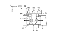
- FIG. 2 is a schematic plan view of the holding portion 5 according to the embodiment.
- FIG. 3 is a schematic side view of the holding part 5 according to the embodiment. 2 and 3 show the first holding portion 5_1 as an example, the configurations of the second holding portion 5_2 to the fourth holding portion 5_4 are also the same as the first holding portion 5_1.
- the holding portion 5 includes a base portion 50, a first adjusting portion 51, a second adjusting portion 52, a rotating portion 53, an arm portion 54, and a suction portion 55.
- the adsorption part 55 adsorbs and holds the substrate S.
- the suction unit 55 includes a plurality of suction pads 551 .
- a plurality of suction pads 551 are provided side by side in the horizontal direction (here, Y-axis direction). Although an example in which the suction unit 55 includes three suction pads 551 is shown here, the number of suction pads 551 is not limited to three.
- the suction unit 55 holds the substrate S by sucking the lower surface of the substrate S with a plurality of suction pads 551 .
- the base part 50 is fixed on the moving part 4 .
- the first adjusting portion 51 is provided on the base portion 50 and is movable on the base portion 50 along the left-right direction (X-axis direction).
- the second adjuster 52 is provided on the first adjuster 51 and is movable on the first adjuster 51 in the front-rear direction (Y-axis direction).
- the rotating portion 53 is provided on the second adjusting portion 52 and is rotatable around the vertical axis (Z-axis).
- the arm portion 54 is a member that extends in the horizontal direction, is supported by the rotating portion 53 at its proximal end, and supports the suction portion 55 at its distal end.
- first adjusting section 51 and the second adjusting section 52 each have a driving section such as a motor, and can move independently.
- the rotating portion 53 is, for example, a bearing, does not have a driving portion, and rotates the adsorption portion 55 so as to follow the movements of the first adjusting portion 51 and the second adjusting portion 52 .
- a drive part may be provided in the rotation part 53.
- the pair of guide rails 3 extends along the front-rear direction (Y-axis direction), which is the transport direction of the substrate S.
- the length of the pair of guide rails 3 in the front-rear direction (Y-axis direction) is approximately 3 to 7 m.
- the pair of guide rails 3 since the pair of guide rails 3 is long, it is difficult to form them completely straight, and there is a possibility that a distortion of, for example, several ⁇ m may occur in the left-right direction (X-axis direction). Similarly, the pair of guide rails 3 may be distorted by several ⁇ m in the vertical direction (Z-axis direction). Moreover, even if the pair of guide rails 3 can be formed straight, there is a possibility that they will be distorted afterward due to environmental changes (for example, temperature changes).
- FIGS. 4 and 5 the guide rails 3 and the holding portion 5 when the pair of guide rails 3 are not distorted are indicated by dashed lines. As indicated by solid lines in FIGS. 4 and 5, in FIGS. 4 and 5, the strain generated in the pair of guide rails 3 is exaggerated for easy understanding.
- the holding portion 5 provided on the first guide rail 3_1 side and the holding portion 5 provided on the second guide rail 3_2 side The distance between is also changed.
- the fourth gap G4 which is the distance between the second holding portion 5_2 and the fourth holding portion 5_4, is is longer than the fourth interval G4.
- the third gap G3 and the fourth gap G4 when the guide rail 3 is distorted are the same as those when the guide rail 3 is not distorted. It may be shorter than the 3rd interval G3 and the 4th interval G4.
- changes in the third gap G3 and the fourth gap G4 can also occur when only one of the pair of guide rails 3 is distorted.
- the substrate processing apparatus 1 includes a measurement system 100.
- the measurement system 100 is an example of a distance measuring unit that measures the distance between adjacent holding portions 5 among the plurality of holding portions 5 .
- the measuring system 100 is also an example of a moving distance measuring unit that measures the moving distances of the first moving unit 4 and the second moving unit 4 along the front-rear direction (Y-axis direction).
- the measurement system 100 measures the distance to the measurement site using laser interferometry.
- the measurement system 100 includes a light projecting unit 110 that projects a laser beam, a light receiving unit 120 that receives the laser light projected from the light projecting unit 110, and light of the laser light from the light projecting unit 110 to the light receiving unit 120. and an optical system 130 arranged on the road.
- the light projecting section 110 includes a light source 111, a plurality of beam splitters 112-115, and a plurality of beam benders 116-118.
- the light source 111 generates laser light.
- a plurality of beam splitters 112 to 115 split the incident laser light into two laser lights at a predetermined splitting ratio.
- a plurality of beam benders 116-118 change the traveling direction of the incident laser light.
- the beam splitter 112 splits the laser light incident from the light source 111 and projects the split light toward the beam splitter 113 and an interferometer 134d, which will be described later.
- the beam splitter 113 splits the laser light incident from the beam splitter 112 and projects the split light toward the beam splitter 114 and the beam bender 116 .
- the beam splitter 114 splits the laser light incident from the beam splitter 113 and projects the split light toward a beam bender 118 and an interferometer 134b, which will be described later.
- the beam splitter 115 splits the laser light incident from a beam bender 116 described later and projects the split light toward a beam bender 117 and a beam splitter 132 described later.
- the beam bender 116 changes the traveling direction of the laser incident from the beam splitter 113 by 90 degrees and projects the light toward the beam splitter 115 .
- the beam bender 117 changes the traveling direction of the laser incident from the beam splitter 115 by 90 degrees and projects the light toward an interferometer 134c described later.
- the beam bender 118 changes the traveling direction of the laser incident from the beam splitter 114 by 90 degrees, and projects the light toward an interferometer 134a, which will be described later.
- the light receiving unit 120 includes a plurality of light receivers 121-126.
- the light receiver 121 receives the laser beam reflected at the measurement site 131a described later
- the light receiver 122 receives the laser light reflected at the measurement site 131b described later
- the light receiver 123 receives the laser light reflected at the measurement site 131c described later.
- the light receiver 124 receives the laser beam reflected at the measurement site 131d described later
- the light receiver 125 receives the laser light reflected at the measurement site 131e described later
- the light receiver 126 receives the laser light reflected at the measurement site 131f described later. receives the laser light reflected at the
- the light projecting unit 110, the light receiving unit 120, and the optical system 130 are arranged along the front-rear direction (Y-axis direction).
- the light receivers 121 to 126 are positioned on the Y-axis positive direction side of the light projecting unit 110 and on the Y-axis negative direction side of the optical system 130. It is located on the Y-axis positive direction side of the system 130 .
- a plurality of measurement sites 131a to 131f are sites irradiated with laser light.
- the plurality of measurement sites 131a to 131f have reflecting surfaces perpendicular to the incident laser light.
- the beam splitter 132 is provided on the first holding portion 5_1.
- the beam splitter 132 splits the laser light incident from the beam splitter 115 and projects the split light toward the interferometer 134 e and the beam bender 133 .
- the beam bender 133 is provided in the second adjuster 52 .
- the beam bender 133 changes the traveling direction of the laser light incident from the beam splitter 132 by 90 degrees and projects the laser light toward the interferometer 134f.
- the plurality of interferometers 134a to 134f for example, split the incident laser light into two laser lights using a beam splitter provided inside. Also, the plurality of interferometers 134a to 134f reflect one of the split laser beams by a reflecting mirror provided inside. The laser light (reference path) reflected by the reflecting mirrors in the interferometers 134a to 134f and the laser light (measurement path) reflected by the measurement sites 131a to 131f are separated by the beam splitters in the interferometers 134a to 134f. They are recombined and enter photodetectors 121-126.
- the measurement system 100 measures the distances to the measurement sites 131a-131f based on the phase difference between the two laser beams obtained by optical signal processing of the laser beams received by the light receivers 121-126.
- the interferometer 134a is arranged at a position separated from the first moving part 4_1 between the light receiver 121 and the measurement site 131a.
- the interferometer 134a splits the laser light projected from the beam bender 118 into two.
- One of the two laser beams split by the interferometer 134a is projected toward the reflecting mirror inside the interferometer 134a, and the other is projected toward the measurement site 131a.
- the laser light recombined in the interferometer 134 a is received by the light receiver 121 .
- the measurement system 100 can obtain the distance from the interferometer 134a to the measurement site 131a, that is, the first moving distance D1, which is the moving distance of the first moving part 4_1. .
- the interferometer 134b is arranged at a position separated from the second moving part 4_2 between the light receiver 122 and the measurement site 131b.
- the interferometer 134b splits the laser light projected from the beam splitter 114 into two.
- One of the two laser beams split by the interferometer 134b is projected toward the reflecting mirror inside the interferometer 134b, and the other is projected toward the measurement site 131b.
- the laser light recombined in the interferometer 134 b is received by the photodetector 122 .
- the measurement system 100 can obtain the distance from the interferometer 134b to the measurement site 131b, that is, the second moving distance D2, which is the moving distance of the second moving part 4_2. .
- the interferometer 134c is provided in the first holding portion 5_1.
- the interferometer 134c splits the laser light projected from the beam bender 117 into two.
- One of the two laser beams split by the interferometer 134c is projected toward the reflecting mirror inside the interferometer 134c, and the other is projected toward the measurement site 131c.
- the laser light recombined in the interferometer 134 c is received by the light receiver 123 .
- the measurement system 100 determines the distance from the interferometer 134c to the measurement site 131b, that is, the distance between the first holding portion 5_1 and the second holding portion 5_2. can be obtained.
- the interferometer 134d is provided in the third holding part 5_3.
- the interferometer 134d splits the laser light projected from the beam splitter 112 into two.
- One of the two laser beams split by the interferometer 134d is projected toward the reflector within the interferometer 134d, and the other is projected toward the measurement site 131d.
- the laser light recombined in the interferometer 134 d is received by the photodetector 124 . Based on the laser light received by the light receiver 124, the measurement system 100 determines the distance from the interferometer 134d to the measurement site 131d, i. can be obtained.
- the interferometer 134e is provided in the first holding portion 5_1.
- a laser beam projected from the beam splitter 115 and split by the beam splitter 132 is incident on the interferometer 134e.
- the interferometer 134e splits the laser light incident from the beam splitter 132 into two.
- One of the two laser beams split by the interferometer 134e is projected toward the reflecting mirror inside the interferometer 134e, and the other is projected toward the measurement site 131e.
- the laser light recombined in the interferometer 134 e is received by the photodetector 125 . Based on the laser light received by the light receiver 125, the measurement system 100 determines the distance from the interferometer 134e to the measurement site 131e, i. can be obtained.
- the interferometer 134f is provided in the second holding portion 5_2.
- a laser beam projected from the beam splitter 132 and having its course changed by the beam bender 133 is incident on the interferometer 134f.
- the interferometer 134f splits the laser light incident from the beam bender 133 into two.
- One of the two laser beams split by the interferometer 134f is projected toward the reflecting mirror inside the interferometer 134f, and the other is projected toward the measurement site 131f.
- the laser light recombined in the interferometer 134f is received by the photodetector 126.
- FIG. Based on the laser light received by the light receiver 126, the measurement system 100 determines the distance from the interferometer 134f to the measurement site 131f, i. can be obtained.
- the interferometers 134c and 134e and the beam splitter 132 provided in the first holding unit 5_1 of the optical system 130 are the first adjustment unit 51 and the second adjustment unit 52. It is provided in the adjustment part located above. With such a configuration, the height positions of the interferometers 134c and 134e and the beam splitter 132 can be brought closer to the height position of the substrate S, so that the first gap G1 and the third gap G3 can be measured with higher accuracy. can be done.
- the rotation of the rotating portion 53 reduces the measurement accuracy of the first gap G1 and the third gap G3. can be suppressed.
- the embodiment shows an example in which the second adjustment section 52 is provided on the first adjustment section 51
- the first adjustment section 51 may be provided on the second adjustment section 52
- interferometers 134 c and 134 e and beam splitter 132 may be provided in first adjustment section 51 .
- the measurement system 100 When measuring the first gap G1 and the third gap G3, the measurement system 100 lifts the stage 151 using the lifting mechanism 150 to move the interferometers 134c and 134e and the beam splitter 132 to the upper surface of the adsorption unit 55 ( That is, it is positioned above the adsorption surface). With this configuration, the height positions of the interferometers 134c and 134e and the beam splitter 132 can be brought closer to the height position of the substrate S, so that the first gap G1 and the third gap G3 can be measured with higher accuracy. be able to.
- the measurement system 100 When measurement is not performed, the measurement system 100 lowers the interferometers 134 c and 134 e and the beam splitter 132 using the elevating mechanism 150 to position them below the upper surface of the adsorption unit 55 . This can prevent the interferometers 134c and 134e and the beam splitter 132 from interfering with the transportation of the substrate S.
- FIG. 7 shows, as an example, the arrangement of the interferometers 134c and 134e and the beam splitter 132 provided in the first holding section 5_1.
- part of the optical system 130 (the beam bender 133 and the interferometer 134f) provided in the second holding part 5_2 and part of the optical system 130 (the interferometer 134d) provided in the third holding part 5_3 are also raised and lowered. It is provided in the second adjusting section 52 via the mechanism 150 .
- the measurement portion 131a provided in the first holding section 5_1 of the optical system 130 is provided below the first adjustment section 51 and the second adjustment section 52.
- the guide rail 3 is distorted in the vertical direction (Z-axis direction)
- the measurement portion 131a is provided in the first adjusting portion 51 or the second adjusting portion 52. Therefore, it is possible to accurately measure the first moving distance D1.
- FIG. 7 shows an example in which the measurement site 131a is provided on the first moving section 4_1.
- the measurement site 131a is provided at a location located below the first adjusting section 51 and the second adjusting section 52 among members other than the first moving section 4_1 that move together with the first moving section 4_1.
- measurement site 131 a may be provided on base portion 50 .
- the measurement site 131a may be provided in the first adjusting section 51 or may be provided in the second adjusting section 52, for example, without being limited to the example described above. By providing the measurement portion 131a at a position close to the substrate S, the first moving distance D1 can be measured with high accuracy.
- the light projecting section 110, the light receivers 121 and 122, the measurement sites 131a and 131b, and the interferometers 134a and 134b are an example of the moving distance measuring section.
- the light projecting unit 110, the light receiving unit 121, the measurement part 131a, and the interferometer 134a are used for first movement distance measurement for measuring the movement distance of the first moving part 4_1 along the front-rear direction (Y-axis direction). This is an example of a part.
- the light projecting section 110, the light receivers 123 to 126, the measurement sites 131c to 131f, the beam splitter 132, the beam bender 133, and the interferometers 134c to 134f measure the distance between the adjacent holding sections 5. It is an example of an interval measurement unit that Specifically, the light projecting unit 110, the light receiving unit 123, the measurement part 131c, and the interferometer 134c are an example of a first distance measuring unit that measures the first distance G1. Further, the light projecting section 110, the light receiver 124, the measurement site 131d, and the interferometer 134d are an example of a second distance measuring section that measures the second distance G2.
- FIG. 8 is a block diagram showing the configuration of the control device 8 according to the embodiment.
- the control device 8 includes a control section 81 and a storage section 82 .
- the control unit 81 is a controller.
- the control unit 81 is realized by executing various programs stored in a storage device inside the control device 8 using the RAM as a work area, for example, by a CPU (Central Processing Unit) or MPU (Micro Processing Unit). be.
- the control unit 81 is a controller, and is implemented by an integrated circuit such as an ASIC (Application Specific Integrated Circuit) or an FPGA (Field Programmable Gate Array).
- the control unit 81 includes a measurement processing unit 811, a change processing unit 812, and a transport processing unit 813, and implements or executes processing functions and actions described below.
- the storage unit 82 is implemented by, for example, a semiconductor memory device such as RAM (Random Access Memory) or flash memory, or a storage device such as a hard disk or optical disk. As shown in FIG. 8 , the storage unit 82 stores transport information 821 , first moving unit adjustment information 822 and second moving unit adjustment information 823 . The storage unit 82 also stores first holding portion adjustment information 824 , second holding portion adjustment information 825 , third holding portion adjustment information 826 , and fourth holding portion adjustment information 827 .
- a semiconductor memory device such as RAM (Random Access Memory) or flash memory
- FIG. 8 the storage unit 82 stores transport information 821 , first moving unit adjustment information 822 and second moving unit adjustment information 823 .
- the storage unit 82 also stores first holding portion adjustment information 824 , second holding portion adjustment information 825 , third holding portion adjustment information 826 , and fourth holding portion adjustment information 827 .
- the transport information 821 is information indicating the amount of movement instructed to the moving part 4 and the holding part 5 at each point on the pair of guide rails 3 .
- Each point on the pair of guide rails 3 is, for example, the distance from the starting point of the transport path of the substrate S (the movement distance of the moving part 4 when it is assumed that the pair of guide rails 3 are not distorted, hereinafter referred to as "ideal movement distance”).
- a movement command for the moving part 4 and the holding part 5 is output, for example, every 50 mm of the ideal movement distance.
- the transport information 821 is associated with the amount of movement instructed to the first moving unit 4_1 and the second moving unit 4_2 for each ideal moving distance of 50 mm.
- 50 mm may be associated with each ideal movement distance of 50 mm as a movement amount instructed to the first moving section 4_1 and the second moving section 4_2.
- the first moving part 4_1 and the second moving part 4_2 move 50 mm on the guide rail each time a movement instruction is received.
- the transport information 821 may be associated with, for example, the amount of movement in consideration of the distortion of the pair of guide rails 3, which is obtained based on prior measurements using a laser interferometer or the like. For example, when a movement command for a movement amount of 50 mm was output to the first moving unit 4_1 at a point with an ideal movement distance of 100 mm, it was found from previous measurements that the point actually reached was 149 mm. Suppose In this case, the transport information 821 may be associated with a movement amount of 51 mm for an ideal movement distance of 100 mm. By outputting such a movement command and moving the first moving part 4_1 and the second moving part 4_2 by 51 mm, the first moving part 4_1 and the second moving part 4_2 can be made to reach the point of 150 mm.
- the information associated with the movement amount in the transport information 821 is the ideal movement distance
- the information associated with the movement amount in the transport information 821 is the movement command for the moving unit 4 and the holding unit 5. It may be the number of outputs. That is, the transport information 821 may be information in which the movement amount included in the movement command is associated with the number of times the movement command is output to the moving unit 4 and the holding unit 5 .
- the transport information 821 is associated with the movement amount instructed to the first holding part 5_1 to the fourth holding part 5_4 for each ideal movement distance of 50 mm, for example.
- the transport information 821 for each holding unit 5 is the amount of movement of the first adjustment unit 51 (hereinafter referred to as “X movement amount”) and the second adjustment with respect to the ideal movement distance (or the number of times the movement command is output). It is information that associates the amount of movement of the unit 52 (hereinafter referred to as "Y movement amount").
- X movement amount the amount of movement of the first adjustment unit 51
- Y movement amount the transport information 821 for each holding portion 5 considers the distortion of the pair of guide rails 3 based on, for example, prior measurements.
- the transport information 821 for each holding portion 5 may not consider the distortion of the pair of guide rails 3 .
- "0" is associated with the ideal movement distance (or the number of times the movement command is output) as the X movement amount and the Y movement amount.
- Each of the adjustment information 822 to 827 including the first moving part adjustment information 822 is information for adjusting the movement amount associated with the transport information 821 .
- the first moving part adjustment information 822 is information indicating an adjustment value for adjusting the movement amount included in the movement command output to the first moving part 4_1 at each point on the first guide rail 3_1.
- the second moving part adjustment information 823 is information indicating an adjustment value for adjusting the amount of movement included in the movement command output to the second moving part 4_2 at each point on the second guide rail 3_2. be.
- FIG. 9 is a diagram showing an example of first moving unit adjustment information 822 according to the embodiment.
- the first moving part adjustment information 822 is information in which the item "number of output of movement commands", the item “ideal movement distance”, and the item “adjustment value” are associated with each other.
- the number of times a move command is output to the first mover 4_1 is stored in the "number of times move command is output" item.
- the first movement distance after the movement command is output the number of times stored in the corresponding "output number of movement commands"
- the ideal moving distance of the part 4_1 is stored.
- the “adjustment value” item stores the adjustment value of the movement amount stored in the transport information 821 for the first moving unit 4_1.
- the ideal movement distance "50 (mm)” and the adjustment value "-1 ( ⁇ m)" are associated with the number of times the movement command is output “1 (times)". This indicates that the ideal moving distance of the first moving section 4_1 when the first moving command is output to the first moving section 4_1 is "50 (mm)". Further, the transport information 821 indicates that the movement amount associated with the first movement command for the first moving section 4_1 is adjusted by "-1 ( ⁇ m)".
- the positive and negative values of the “adjustment value ( ⁇ m)” shown in FIG. 9 are “+” when adjusting in the positive direction of the Y-axis and “-” when adjusting in the negative direction of the Y-axis.
- the first holding portion adjustment information 824 is information indicating an adjustment value for adjusting the movement amount included in the movement command output to the first holding portion 5_1 at each point on the first guide rail 3_1.
- the second holding portion adjustment information 825 is information indicating an adjustment value for adjusting the amount of movement included in the movement command output to the second holding portion 5_2 at each point on the first guide rail 3_1.
- the third holding portion adjustment information 826 is information indicating an adjustment value for adjusting the movement amount included in the movement command output to the third holding portion 5_3 at each point on the second guide rail 3_2. be.
- the fourth holding portion adjustment information 827 is information indicating an adjustment value for adjusting the movement amount included in the movement command output to the fourth holding portion 5_4 at each point on the second guide rail 3_2. be.
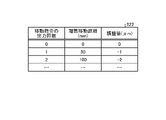
- FIG. 10 is a diagram illustrating an example of first holding unit adjustment information 824 according to the embodiment.
- the first holding unit adjustment information 824 includes an item of "number of output of movement commands", an item of "ideal movement distance”, an item of "X adjustment value”, and an item of "Y adjustment value”. This is associated information.
- the number of times the movement command is output to the first adjustment section 51 and the second adjustment section 52 included in the first holding section 5_1 is stored in the "output number of movement commands" item.
- the "ideal movement distance” item when it is assumed that the pair of guide rails 3 are not distorted, the first movement distance after the movement command is output the number of times stored in the corresponding "output number of movement commands"
- the ideal moving distance of the part 4_1 is stored.
- the "X adjustment value” item stores a value for adjusting the X movement amount stored in the transport information 821 for the first holding unit 5_1.
- the "Y adjustment value” item stores a value for adjusting the Y movement amount stored in the transport information 821 for the first holding unit 5_1.
- the ideal movement distance is 50 (mm)
- the X adjustment value is 0 ( ⁇ m)
- the Y adjustment value is 3 ( ⁇ m) for the number of output movement commands of 1 (times). )” is associated.
- the ideal moving distance of the first moving part 4_1 when the first moving command is output to the first holding part 5_1 is "50 (mm)”.
- the X movement amount associated with the first movement command to the first holding unit 5_1 is adjusted to "0 ( ⁇ m)”
- the Y movement amount is adjusted to "3 ( ⁇ m)”. ing.
- the control part 81 adjusts the adjusting part of each holding part 5 so that the measurement result by the measuring system 100 is constant. It controls and adjusts the position of the adsorption part 55 with respect to the moving part 4 .
- the control section 81 includes a measurement processing section 811 , a change processing section 812 and a transport processing section 813 .
- the measurement processing unit 811 performs measurement by the measurement system 100 while moving the first moving unit 4_1 and the second moving unit 4_2 along the pair of guide rails 3 . As a result, the information of the first movement distance D1, the first gap G1, the third gap G3, and the fourth gap G4 at each point on the first guide rail 3_1 and the second movement distance at each point on the second guide rail 3_2 are obtained. Information of the distance D2 and the second spacing G2 is obtained.
- the measurement processing by the measurement processing unit 811 is performed while the substrates S are not held by the plurality of holding units 5 .
- the change processing unit 812 changes the first moving unit adjustment information 822 stored in the storage unit 82 based on the measurement result of the first moving distance D1 measured by the measurement system 100 in the measurement processing by the measurement processing unit 811. Similarly, the change processing unit 812 changes the second movement unit adjustment information 823 stored in the storage unit 82 based on the measurement result of the second movement distance D2 measured by the measurement system 100 in the measurement processing by the measurement processing unit 811. change.
- the change processing unit 812 for each movement command to the first moving part 4_1 (every time the first moving part 4_1 moves according to the movement command), changes the first moving part 4_1 after the first moving part 4_1 moves according to the movement command. It is determined whether or not the distance D1 has deviated from the ideal moving distance. Then, when it is determined that the first moving distance D1 deviates from the ideal moving distance, the change processing unit 812 adjusts the movement in the first moving part adjustment information 822 so that the first moving distance D1 matches the ideal moving distance. Change the adjustment value associated with the command. For example, assume that the first moving distance D1 after the first moving part 4_1 moves according to the third movement command is deviated from the ideal moving distance by -1 ⁇ m. In this case, the change processing unit 812 adds 1 ⁇ m to the adjustment value associated with the third movement command in the first movement unit adjustment information 822 .
- the change processing unit 812 performs the first holding unit adjustment stored in the storage unit 82 based on the measurement results of the first interval G1 to the fourth interval G4 measured by the measurement system 100 in the measurement processing by the measurement processing unit 811.
- Information 824 to fourth holding unit adjustment information 827 are changed.
- the change processing unit 812 determines whether the first interval G1 has changed from the first specified value for each point on the first guide rail 3_1.
- “at each point on the first guide rail 3_1” can be rephrased as “each move command to the first moving part 4_1” or "each time the first moving part 4_1 moves according to the move command”.
- the first specified value is the value obtained when it is assumed that each of the suction portions 55 of the first holding portion 5_1 and the suction portions 55 of the second holding portion 5_2 is correctly sucking and holding the substrate S at a prescribed position. This is the ideal value for the first interval G1. If the first guide rail 3_1 is straight without being distorted, the first gap G1 is maintained at the first specified value from the start point to the end point of the substrate S transport path.
- the change processing unit 812 changes the first holding unit adjustment information 824 or the second holding unit adjustment information 825 so that the first interval G1 at that point matches, for example, the first specified value in the next transportation process. change.
- the change processing unit 812 changes the first holding unit adjustment information 824 . Specifically, the change processing unit 812 changes the Y adjustment value corresponding to the point at which the first interval G1 has changed (the number of times the movement command is output) in the first holding unit adjustment information 824 . For example, assume that the first gap G1 changes from the first specified value by "-1 ⁇ m" after the first moving part 4_1 moves according to the second movement command. In this case, the change processing unit 812 subtracts 1 ⁇ m from the Y adjustment value “4 ( ⁇ m)” associated with the movement command output count “2” in the first holding unit adjustment information 824 to obtain “3 ( ⁇ m)”. )”.
- the change processing unit 812 may change the Y adjustment value of the second holding unit adjustment information 825 .
- the change processing unit 812 changes the position at the one point in the transport process after the measurement process.
- the amount of movement of the first adjustment portion 51, which is one of the first holding portion 5_1 and the second holding portion 5_2, at the one point is adjusted so that the first gap G1 at .theta.
- the first distance G1 at the one point can be maintained at the first predetermined value. That is, the relative positions of the first holding portion 5_1 and the second holding portion 5_2 at the one point can be maintained.
- the change processing unit 812 determines whether or not the second interval G2 has changed from the second specified value for each point on the second guide rail 3_2.
- the second specified value is the second specified value when it is assumed that each of the adsorption portions 55 of the third holding portion 5_3 and the adsorption portions 55 of the fourth holding portion 5_4 correctly adsorbs and holds the substrate S at a specified position. This is the ideal value for the interval G2.
- the change processing unit 812 changes the third holding unit adjustment information 826 or the fourth holding unit adjustment information 827 so that the second interval G2 at that point matches the second specified value in the next transportation process, for example. do.
- the change processing unit 812 changes the third holding unit adjustment information 826 .
- the change processing unit 812 changes the Y adjustment value corresponding to the point (the number of times the movement command is output) at which the second interval G2 changes in the third holding unit adjustment information 826 .
- the change processing unit 812 may change the Y adjustment value of the fourth holding unit adjustment information 827 .
- the change processing unit 812 determines whether or not the third interval G3 has changed from the third specified value for each point on the first guide rail 3_1.
- the third specified value is the third specified value when it is assumed that each of the suction portions 55 of the first holding portion 5_1 and the suction portions 55 of the third holding portion 5_3 is correctly sucking and holding the substrate S at a prescribed position. This is the ideal value for the interval G3.
- the change processing unit 812 changes the first holding unit adjustment information 824 or the third holding unit adjustment information 826 so that the third interval G3 at that point matches the third specified value in the next transportation process, for example. do.
- the change processing unit 812 changes the first holding unit adjustment information 824 .
- the change processing unit 812 changes the X adjustment value corresponding to the point (the number of times the movement command is output) at which the third interval G3 has changed in the first holding unit adjustment information 824 .
- the change processing unit 812 may change the X adjustment value of the third holding unit adjustment information 826 .
- the change processing unit 812 adds 1 ⁇ m to the X adjustment value “5 ( ⁇ m)” associated with the movement command output count “2” in the first holding unit adjustment information 824 to obtain “6 ( ⁇ m)”. )”.
- the second adjustment part 52 of the first holding part 5_1 is The amount of movement included in the output movement command is adjusted.
- the change processing unit 812 may change the X adjustment value of the third holding unit adjustment information 826 .
- the change processing unit 812 changes the position at the one point in the transport process after the measurement process.
- the amount of movement of the second adjusting portion 52, which is one of the first holding portion 5_1 and the third holding portion 5_3, at the one point is adjusted so that the third gap G3 at the point coincides with the third specified value.
- the third gap G3 at the one point can be maintained at the third default value. That is, the relative positions of the first holding portion 5_1 and the third holding portion 5_3 at the one point can be maintained.
- the change processing unit 812 determines whether the fourth interval G4 has changed from the fourth specified value for each point on the first guide rail 3_1.
- the fourth specified value is the fourth specified value when it is assumed that each of the adsorption portions 55 of the second holding portion 5_2 and the adsorption portions 55 of the fourth holding portion 5_4 correctly adsorbs and holds the substrate S at a specified position. This is the ideal value for the interval G4.
- the change processing unit 812 changes the second holding unit adjustment information 825 or the fourth holding unit adjustment information 827 so that the fourth interval G4 at that point matches the fourth specified value in the next transportation process, for example. do.
- the change processing unit 812 changes the second holding unit adjustment information 825 .
- the change processing unit 812 changes the X adjustment value corresponding to the point (the number of times the movement command is output) at which the fourth interval G4 changes in the second holding unit adjustment information 825 .
- the change processing unit 812 may change the X adjustment value of the fourth holding unit adjustment information 827 .
- the transport processing unit 813 controls the first moving unit 4_1 using the transport information 821 and the first moving unit adjustment information 822 to determine the amount of movement of the first moving unit 4_1 at each point on the first guide rail 3_1. adjust. Specifically, the transport processing unit 813 adjusts the movement amount of the first moving unit 4_1 stored in the transport information 821 using the adjustment value stored in the first moving unit adjustment information 822 . Then, the transport processing unit 813 outputs a movement command including the adjusted movement amount to the first moving unit 4_1.
- the transport processing unit 813 controls the second moving unit 4_2 using the transport information 821 and the second moving unit adjustment information 823 to move the second moving unit 4_2 at each point on the second guide rail 3_2. Adjust quantity. Specifically, the transport processing unit 813 adjusts the movement amount of the second moving unit 4_2 stored in the transport information 821 using the adjustment value stored in the second moving unit adjustment information 823 . Then, the transport processing section 813 outputs a movement command including the adjusted movement amount to the second movement section 4_2.
- the transport processing unit 813 uses the transport information 821 and the first holding unit adjustment information 824 to control the second adjusting unit 52 of the first holding unit 5_1, so that each point on the first guide rail 3_1 Adjust the amount of movement of the second adjuster 52 . Specifically, the transport processing unit 813 adjusts the movement amount of the second adjustment unit 52 stored in the transport information 821 using the adjustment value stored in the first holding unit adjustment information 824 . Then, the transport processing unit 813 outputs a movement command including the adjusted movement amount to the second adjustment unit 52 of the first holding unit 5_1.
- the transport processing unit 813 uses the transport information 821 and the second holding unit adjustment information 825 to control the first adjusting unit 51 and the second adjusting unit 52 of the second holding unit 5_2. Further, the transport processing unit 813 uses the transport information 821 and the third holding unit adjustment information 826 to control the first adjustment unit 51 and the second adjustment unit 52 of the third holding unit 5_3. Further, the transport processing unit 813 uses the transport information 821 and the fourth holding unit adjustment information 827 to control the first adjusting unit 51 and the second adjusting unit 52 of the fourth holding unit 5_4.
- the transport processing unit 813 moves the first moving unit 4_1 and the second moving unit 4_2 along the pair of guide rails 3
- the first adjusting unit 51 moves on the basis of the measurement results obtained by the measurement process.
- the second adjuster 52 to adjust the position of the suction part 55 at each point of the pair of guide rails.
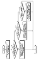
- FIG. 11 is a flow chart showing procedures of the measurement process and the change process among the processes executed by the substrate processing apparatus 1 according to the embodiment. Each process shown in FIG. 11 is executed under the control of the control device 8 .
- the substrate processing apparatus 1 performs measurement processing. Specifically, the control unit 81 performs measurement by the measurement system 100 while moving the moving unit 4 and the holding unit 5 (step S101). At this time, the control section 81 moves the first moving section 4_1 by controlling the first moving section 4_1 using the transport information 821 and the first moving section adjustment information 822 . Further, the control section 81 moves the second moving section 4_2 by controlling the second moving section 4_2 using the transport information 821 and the second moving section adjustment information 823 . Further, the control unit 81 uses the transport information 821 and the first holding unit adjustment information 824 to move the first holding unit 5_1, and uses the transport information 821 and the second holding unit adjustment information 825 to move the second holding unit 5_2. move. Further, the control unit 81 uses the transport information 821 and the third holding unit adjustment information 826 to move the third holding unit 5_3, and uses the transport information 821 and the fourth holding unit adjustment information 827 to move the fourth holding unit 5_4. move.
- the control unit 81 uses the measurement system 100 to determine the first moving distance D1, the second moving distance D2, and the A first interval G1 to a fourth interval G4 are measured.
- control unit 81 determines whether or not the first moving distance D1 or the second moving distance D2 has changed from the ideal moving distance (step S102).
- step S102 When it is determined in step S102 that the first movement distance D1 or the second movement distance D2 has changed from the ideal movement distance (step S102; Yes), the control unit 81 determines that the first movement distance D1 or the second movement distance D2 is The adjustment value of the first moving unit 4_1 or the second moving unit 4_2 is changed so as to match the ideal moving distance (step S103).
Abstract
A substrate transfer device according to an embodiment of the present invention comprises a pair of guide rails, a first moving unit, a second moving unit, a plurality of holding parts, a space measuring unit, and a control unit. The pair of guide rails are aligned in a first direction and extend in a second direction that is orthogonal to the first direction. The plurality of holding parts are each provided on the first moving unit and second moving unit and hold a substrate, from the bottom thereof, by suction. The space measuring unit measures the distance between holding parts which are, from among the plurality of holding parts, adjacent to one another. The control unit controls the first moving unit, the second moving unit, and the plurality of holding parts. The plurality of holding parts comprise a suction unit for holding the substrate by suction and an adjustment unit for adjusting the position of the suction unit. The control unit transfers the substrate while controlling the adjustment unit to adjust the position of the suction unit such that measurement results by the space measuring unit remain constant as the first moving unit and second moving unit are moving along the pair of guide rails.
Description
本開示は、基板搬送装置、塗布処理装置、基板搬送方法および基板搬送プログラムに関する。
The present disclosure relates to a substrate transfer apparatus, a coating processing apparatus, a substrate transfer method, and a substrate transfer program.
特許文献1には、基板の搬送方向に延びる2本のガイドレールに沿って基板を搬送し、基板に機能液の液滴を吐出することが開示されている。
Patent Document 1 discloses that a substrate is transported along two guide rails extending in the transport direction of the substrate, and droplets of functional liquid are ejected onto the substrate.
本開示は、基板搬送における誤差を低減する技術を提供する。
The present disclosure provides a technique for reducing errors in substrate transfer.
本開示の一態様による基板搬送装置は、一対のガイドレールと、第1移動部と、第2移動部と、複数の保持部と、間隔測定部と、制御部とを備える。一対のガイドレールは、第1方向に並べられ且つ第1方向と直交する第2方向に沿って延在する。第1移動部は、一対のガイドレールのうち一方のガイドレールに沿って移動する。第2移動部は、一対のガイドレールのうち他方のガイドレールに沿って移動する。複数の保持部は、第1移動部および第2移動部上にそれぞれ設けられ、基板の下方から基板を吸着保持する。間隔測定部は、複数の保持部のうち隣り合う保持部間の距離を測定する。制御部は、第1移動部、第2移動部および複数の保持部を制御する。複数の保持部は、基板を吸着保持する吸着部と、吸着部の位置を調整する調整部とを備える。制御部は、一対のガイドレールに沿って第1移動部および第2移動部が移動する間、間隔測定部による測定結果が一定となるように、調整部を制御して吸着部の位置を調整しながら基板を搬送する。
A substrate transport apparatus according to one aspect of the present disclosure includes a pair of guide rails, a first moving section, a second moving section, a plurality of holding sections, a gap measuring section, and a control section. A pair of guide rails are arranged in a first direction and extend along a second direction orthogonal to the first direction. The first moving part moves along one of the pair of guide rails. The second moving part moves along the other guide rail of the pair of guide rails. A plurality of holding parts are provided on the first moving part and the second moving part, respectively, and hold the substrate by suction from below the substrate. The interval measuring unit measures the distance between adjacent holding portions among the plurality of holding portions. The control section controls the first moving section, the second moving section and the plurality of holding sections. The plurality of holding units includes an adsorption unit that adsorbs and holds the substrate, and an adjustment unit that adjusts the positions of the adsorption units. The control unit controls the adjusting unit to adjust the position of the suction unit so that the measurement result obtained by the distance measuring unit is constant while the first moving unit and the second moving unit move along the pair of guide rails. The substrate is transported while
本開示によれば、基板搬送における誤差を低減することができる。
According to the present disclosure, errors in substrate transfer can be reduced.
以下、添付図面を参照して、本願の開示する基板搬送装置、塗布処理装置、基板搬送方法および基板搬送プログラムの実施形態を詳細に説明する。なお、以下に示す実施形態により開示される基板搬送装置、塗布処理装置、基板搬送方法および基板搬送プログラムが限定されるものではない。
Hereinafter, embodiments of a substrate transfer apparatus, a coating treatment apparatus, a substrate transfer method, and a substrate transfer program disclosed in the present application will be described in detail with reference to the accompanying drawings. It should be noted that the substrate transfer apparatus, the coating treatment apparatus, the substrate transfer method, and the substrate transfer program disclosed by the embodiments shown below are not limited.
以下参照する各図面では、説明を分かりやすくするために、互いに直交するX軸方向、Y軸方向およびZ軸方向を規定し、Z軸正方向を鉛直上向き方向とする直交座標系を示す。
Each drawing referred to below shows an orthogonal coordinate system in which the X-axis direction, the Y-axis direction, and the Z-axis direction are defined to be orthogonal to each other, and the Z-axis positive direction is the vertically upward direction, in order to make the explanation easier to understand.
また、ここでは、Y軸正方向を前方とし、Y軸負方向を後方とする前後方向を規定し、X軸正方向を右方とし、X軸負方向を左方とする左右方向を規定する。また、Z軸正方向を上方とし、Z軸負方向を下方とする上下方向を規定する。基板処理装置1は、基板Sを後方から前方に向けて前後方向に沿って搬送しながら基板Sを処理する。すなわち、基板処理装置1は、搬送方向(Y軸方向)に沿って基板Sを搬送しながら、基板Sを処理する。
Here, the front-rear direction is defined with the positive direction of the Y-axis as the front and the negative direction of the Y-axis as the rear, and the left-right direction with the positive direction of the X-axis as the right and the negative direction of the X-axis as the left. . A vertical direction is defined in which the positive direction of the Z-axis is upward and the negative direction of the Z-axis is downward. The substrate processing apparatus 1 processes the substrate S while transporting the substrate S forward and backward along the front-rear direction. That is, the substrate processing apparatus 1 processes the substrate S while transporting the substrate S along the transport direction (Y-axis direction).
<全体構成>
実施形態に係る基板処理装置1の全体構成について図1を参照して説明する。図1は、実施形態に係る基板処理装置1の一部を示す模式的な平面図である。基板処理装置1は、ワークである基板Sを水平方向に搬送しながら、インクジェット方式で基板Sに描画を行う。基板Sは、例えば、フラットパネルディスプレイに用いられる基板である。 <Overall composition>
An overall configuration of asubstrate processing apparatus 1 according to an embodiment will be described with reference to FIG. FIG. 1 is a schematic plan view showing part of a substrate processing apparatus 1 according to an embodiment. The substrate processing apparatus 1 performs drawing on the substrate S by an inkjet method while horizontally transporting the substrate S as a work. The substrate S is, for example, a substrate used for flat panel displays.
実施形態に係る基板処理装置1の全体構成について図1を参照して説明する。図1は、実施形態に係る基板処理装置1の一部を示す模式的な平面図である。基板処理装置1は、ワークである基板Sを水平方向に搬送しながら、インクジェット方式で基板Sに描画を行う。基板Sは、例えば、フラットパネルディスプレイに用いられる基板である。 <Overall composition>
An overall configuration of a
基板処理装置1は、浮上ステージ2(ステージ部の一例)と、第1ガイドレール3_1と、第2ガイドレール3_2とを備える。また、基板処理装置1は、第1移動部4_1と、第2移動部4_2と、第1保持部5_1と、第2保持部5_2と、第3保持部5_3と、第4保持部5_4とを備える。また、基板処理装置1は、複数の塗布部6と、メンテナンス部7と、制御装置8とを備える。
The substrate processing apparatus 1 includes a floating stage 2 (an example of a stage portion), a first guide rail 3_1, and a second guide rail 3_2. Further, the substrate processing apparatus 1 includes a first moving part 4_1, a second moving part 4_2, a first holding part 5_1, a second holding part 5_2, a third holding part 5_3, and a fourth holding part 5_4. Prepare. The substrate processing apparatus 1 also includes a plurality of coating units 6 , a maintenance unit 7 and a control device 8 .
なお、以下では、第1ガイドレール3_1および第2ガイドレール3_2を総称して「ガイドレール3」と記載することがある。また、第1移動部4_1および第2移動部4_2を総称して「移動部4」と記載することがある。また、第1保持部5_1~第4保持部5_4を総称して「保持部5」と記載することがある。
It should be noted that hereinafter, the first guide rail 3_1 and the second guide rail 3_2 may be collectively referred to as "the guide rail 3". Also, the first moving section 4_1 and the second moving section 4_2 may be collectively referred to as the "moving section 4". In addition, the first holding portion 5_1 to the fourth holding portion 5_4 may be collectively referred to as the “holding portion 5”.
浮上ステージ2は、多数の噴出口(図示せず)を有する。浮上ステージ2は、圧縮されたガス(例えば、空気)を噴出口から基板Sの下面に向けて吹き付け、基板Sに対して上方へ作用する力(以下、「浮上力」と記載する)を与える。浮上ステージ2は、浮上力を与えることで、保持部5の吸着部55(図2参照)に保持された基板Sの浮上高を調整する。すなわち、浮上ステージ2は、保持部5の吸着部55に保持された基板Sに対して下方からガスを吹き付けて、基板Sの浮上高を調整する。
The levitation stage 2 has a large number of ejection ports (not shown). The levitation stage 2 blows compressed gas (for example, air) from an ejection port toward the lower surface of the substrate S to apply a force acting upward on the substrate S (hereinafter referred to as “levitation force”). . The levitation stage 2 adjusts the levitation height of the substrate S held by the adsorption section 55 (see FIG. 2) of the holding section 5 by applying a levitation force. That is, the levitation stage 2 adjusts the floating height of the substrate S by spraying gas from below onto the substrate S held by the adsorption section 55 of the holding section 5 .
浮上ステージ2は、基板Sが搬入される搬入ステージ、および基板Sが搬出される搬出ステージを含む。搬入ステージは、基板処理装置1の後方側(Y軸負方向側)に設けられる。搬出ステージは、基板処理装置1の前方側(Y軸正方向側)に設けられる。
The floating stage 2 includes a loading stage into which the substrate S is loaded and a loading stage into which the substrate S is loaded. The carry-in stage is provided on the rear side (Y-axis negative direction side) of the substrate processing apparatus 1 . The carry-out stage is provided on the front side (the positive Y-axis direction side) of the substrate processing apparatus 1 .
なお、浮上ステージ2は、搬送方向(Y軸方向)に沿って複数設けられてもよい。塗布部6の下方に位置する浮上ステージ2における基板Sの浮上高の範囲は、他の浮上ステージ2における基板Sの浮上高の範囲よりも狭い。例えば、塗布部6の下方に位置する浮上ステージ2における基板Sの浮上高の範囲は、30~60μmである。他の浮上ステージ2における基板Sの浮上高の範囲は、200~2000μmである。
A plurality of levitation stages 2 may be provided along the transport direction (Y-axis direction). The floating height range of the substrate S in the floating stage 2 located below the coating section 6 is narrower than the floating height range of the substrate S in the other floating stages 2 . For example, the floating height range of the substrate S on the floating stage 2 positioned below the coating section 6 is 30 to 60 μm. The floating height range of the substrate S in the other floating stages 2 is 200 to 2000 μm.
例えば、塗布部6の下方に位置する浮上ステージ2では、圧縮された空気を基板Sの下面に向けて吐出するとともに、基板Sと浮上ステージ2との間の空気を吸引することによって、基板Sの浮上高を調整してもよい。
For example, the floating stage 2 positioned below the coating section 6 discharges compressed air toward the lower surface of the substrate S, and sucks the air between the substrate S and the floating stage 2, so that the substrate S may be adjusted.
第1ガイドレール3_1および第2ガイドレール3_2は、左右方向(X軸方向)に並べられ、且つ、搬送方向(Y軸方向)に沿って延在する。
The first guide rail 3_1 and the second guide rail 3_2 are arranged in the horizontal direction (X-axis direction) and extend along the transport direction (Y-axis direction).
第1ガイドレール3_1および第2ガイドレール3_2は、左右方向(X軸方向)において、浮上ステージ2を挟むように配置される。第1ガイドレール3_1は、浮上ステージ2のX軸正方向側に配置され、第2ガイドレール3_2は、浮上ステージ2のX軸負方向側に配置される。第1ガイドレール3_1および第2ガイドレール3_2は、例えば、グラナイトによって構成される。搬送方向(Y軸方向)に直交するガイドレール3の断面は、たとえば矩形状である。
The first guide rail 3_1 and the second guide rail 3_2 are arranged so as to sandwich the levitation stage 2 in the left-right direction (X-axis direction). The first guide rail 3_1 is arranged on the X-axis positive direction side of the levitation stage 2 , and the second guide rail 3_2 is arranged on the X-axis negative direction side of the levitation stage 2 . The first guide rail 3_1 and the second guide rail 3_2 are made of granite, for example. A cross section of the guide rail 3 orthogonal to the transport direction (Y-axis direction) is, for example, rectangular.
第1移動部4_1は、第1ガイドレール3_1上に設けられ、第1ガイドレール3_1に沿って移動する。第2移動部4_2は、第2ガイドレール3_2上に設けられ、第2ガイドレール3_2に沿って移動する。なお、第1移動部4_1および第2移動部4_2は、それぞれモータ等の駆動部を有しており、各々独立して移動することが可能である。
The first moving part 4_1 is provided on the first guide rail 3_1 and moves along the first guide rail 3_1. The second moving part 4_2 is provided on the second guide rail 3_2 and moves along the second guide rail 3_2. The first moving part 4_1 and the second moving part 4_2 each have a driving part such as a motor, and can move independently.
複数の保持部5は、第1移動部4_1および第2移動部4_2上にそれぞれ設けられ、基板Sの下方から基板Sを吸着保持する。
A plurality of holding parts 5 are provided on the first moving part 4_1 and the second moving part 4_2, respectively, and hold the substrate S by suction from below.
具体的には、複数の保持部5のうち、第1保持部5_1および第2保持部5_2は、第1移動部4_1上に設けられ、第3保持部5_3および第4保持部5_4は、第2移動部4_2上に設けられる。第1保持部5_1および第2保持部5_2は、第1移動部4_1上において、搬送方向(Y軸方向)に沿って第1保持部5_1および第2保持部5_2の順番で並べられる。また、第3保持部5_3および第4保持部5_4は、第2移動部4_2上において、搬送方向(Y軸方向)に沿って第3保持部5_3および第4保持部5_4の順番で並べられる。なお、複数の保持部5の数は、4つに限定されない。
Specifically, among the plurality of holding portions 5, the first holding portion 5_1 and the second holding portion 5_2 are provided on the first moving portion 4_1, and the third holding portion 5_3 and the fourth holding portion 5_4 are provided on the first moving portion 4_1. 2 is provided on the moving part 4_2. The first holding portion 5_1 and the second holding portion 5_2 are arranged in the order of the first holding portion 5_1 and the second holding portion 5_2 along the transport direction (Y-axis direction) on the first moving portion 4_1. Further, the third holding portion 5_3 and the fourth holding portion 5_4 are arranged in the order of the third holding portion 5_3 and the fourth holding portion 5_4 along the transport direction (Y-axis direction) on the second moving portion 4_2. Note that the number of the plurality of holding portions 5 is not limited to four.
実施形態において複数(ここでは4つ)の保持部5は、基板Sの四隅を基板Sの下方から吸着保持する。基板Sは、複数の保持部5によって四隅を保持され、且つ、浮上ステージ2によって浮上した状態で、第1移動部4_1および第2移動部4_2によって搬送方向(Y軸正方向)に沿って搬送される。
In the embodiment, a plurality (here, four) of holding parts 5 suck and hold the four corners of the substrate S from below. The substrate S is held at its four corners by a plurality of holders 5 and is transported along the transport direction (Y-axis positive direction) by the first moving part 4_1 and the second moving part 4_2 while being floated by the floating stage 2. be done.
塗布部6は、搬送方向(Y軸正方向)に沿って搬送される基板Sに対して機能液を塗布する。機能液は、インクである。塗布部6は、浮上ステージ2(ステージ部の一例)によって浮上高が調整された基板Sに機能液を塗布する。具体的には、塗布部6は、基板Sに機能液を吐出することによって、機能液を基板Sに塗布する。塗布部6は、左右方向(X軸方向)に沿って複数配置される。図1に示す例では、左右方向(X軸方向)に沿って7つの塗布部6が配置された状態を示しているが、塗布部6の数は、これに限られない。塗布部6は、機能液を吐出する複数のヘッドを有し、各ヘッドから機能液を基板Sに吐出する。
The coating unit 6 applies the functional liquid to the substrate S that is transported along the transport direction (Y-axis positive direction). The functional liquid is ink. The application unit 6 applies the functional liquid to the substrate S whose floating height is adjusted by the floating stage 2 (an example of the stage unit). Specifically, the coating unit 6 coats the substrate S with the functional liquid by discharging the functional liquid onto the substrate S. As shown in FIG. A plurality of application units 6 are arranged along the left-right direction (X-axis direction). Although the example shown in FIG. 1 shows a state in which seven application units 6 are arranged along the left-right direction (X-axis direction), the number of application units 6 is not limited to this. The application unit 6 has a plurality of heads for ejecting functional liquid, and the functional liquid is ejected onto the substrate S from each head.
塗布部6は、Y軸方向に並べられ、且つ、X軸方向に沿って延在する一対のレール9に沿って移動可能である。一対のレール9は、例えば、浮上ステージ2に対して右方に延びるように設けられる。浮上ステージ2の右方における一対のレール9間には、メンテナンス部7が設けられる。塗布部6は、メンテナンス部7の上方となる位置と、基板Sに機能液を吐出する位置との間を移動可能である。塗布部6は、駆動装置、例えば、リニアモータによって、一対のレール9に沿って左右方向に移動する。複数の塗布部6は、独立して左右方向に移動してもよく、一体に左右方向に移動してもよい。
The applicator 6 is movable along a pair of rails 9 arranged in the Y-axis direction and extending along the X-axis direction. A pair of rails 9 are provided, for example, so as to extend rightward with respect to the levitation stage 2 . A maintenance section 7 is provided between a pair of rails 9 on the right side of the levitation stage 2 . The application unit 6 can move between a position above the maintenance unit 7 and a position where the functional liquid is discharged onto the substrate S. As shown in FIG. The application unit 6 is moved in the left-right direction along the pair of rails 9 by a driving device such as a linear motor. The plurality of application units 6 may move independently in the left-right direction, or may move together in the left-right direction.
メンテナンス部7は、塗布部6のヘッドのメンテナンスを行い、塗布部6のヘッドの吐出不良などを解消、または防止する。なお、メンテナンス部7は、浮上ステージ2の上方に設けられてもよい。
The maintenance section 7 performs maintenance of the head of the coating section 6 and eliminates or prevents ejection failures of the head of the coating section 6 . Note that the maintenance section 7 may be provided above the levitation stage 2 .
制御装置8は、たとえばコンピュータであり、制御部81と記憶部82とを備える。記憶部82には、基板処理装置1において実行される各種の処理を制御するプログラムが格納される。制御部81は、記憶部82に記憶されたプログラム(基板搬送プログラムの一例)を読み出して実行することによって基板処理装置1の動作を制御する。
The control device 8 is a computer, for example, and includes a control section 81 and a storage section 82 . The storage unit 82 stores programs for controlling various processes executed in the substrate processing apparatus 1 . The control unit 81 controls the operation of the substrate processing apparatus 1 by reading out and executing a program (an example of a substrate transfer program) stored in the storage unit 82 .
なお、かかるプログラムは、コンピュータによって読み取り可能な記憶媒体に記録されていたものであって、記憶媒体から制御装置8の記憶部82にインストールされたものであってもよい。コンピュータによって読み取り可能な記憶媒体としては、たとえばハードディスク(HD)、フレキシブルディスク(FD)、コンパクトディスク(CD)、マグネットオプティカルディスク(MO)、メモリカードなどがある。
The program may be recorded in a computer-readable storage medium and installed in the storage unit 82 of the control device 8 from the storage medium. Examples of computer-readable storage media include hard disks (HD), flexible disks (FD), compact disks (CD), magnet optical disks (MO), and memory cards.
<保持部>
次に、保持部5の構成について図2および図3を参照して説明する。図2は、実施形態に係る保持部5の模式的な平面図である。また、図3は、実施形態に係る保持部5の模式的な側面図である。なお、図2および図3には、一例として第1保持部5_1を示しているが、第2保持部5_2~第4保持部5_4の構成も第1保持部5_1と同様である。 <Holding part>
Next, the configuration of the holdingportion 5 will be described with reference to FIGS. 2 and 3. FIG. FIG. 2 is a schematic plan view of the holding portion 5 according to the embodiment. Moreover, FIG. 3 is a schematic side view of the holding part 5 according to the embodiment. 2 and 3 show the first holding portion 5_1 as an example, the configurations of the second holding portion 5_2 to the fourth holding portion 5_4 are also the same as the first holding portion 5_1.
次に、保持部5の構成について図2および図3を参照して説明する。図2は、実施形態に係る保持部5の模式的な平面図である。また、図3は、実施形態に係る保持部5の模式的な側面図である。なお、図2および図3には、一例として第1保持部5_1を示しているが、第2保持部5_2~第4保持部5_4の構成も第1保持部5_1と同様である。 <Holding part>
Next, the configuration of the holding
図2および図3に示すように、保持部5は、ベース部50と、第1調整部51と、第2調整部52と、回動部53と、アーム部54と、吸着部55とを備える。
As shown in FIGS. 2 and 3, the holding portion 5 includes a base portion 50, a first adjusting portion 51, a second adjusting portion 52, a rotating portion 53, an arm portion 54, and a suction portion 55. Prepare.
吸着部55は、基板Sを吸着保持する。具体的には、吸着部55は、複数の吸着パッド551を備える。複数の吸着パッド551は、水平方向(ここでは、Y軸方向)に並んで設けられる。なお、ここでは、吸着部55が3つの吸着パッド551を備える場合の例を示しているが、吸着パッド551の数は、3つに限定されない。吸着部55は、複数の吸着パッド551によって、基板Sの下面を吸着し、基板Sを保持する。
The adsorption part 55 adsorbs and holds the substrate S. Specifically, the suction unit 55 includes a plurality of suction pads 551 . A plurality of suction pads 551 are provided side by side in the horizontal direction (here, Y-axis direction). Although an example in which the suction unit 55 includes three suction pads 551 is shown here, the number of suction pads 551 is not limited to three. The suction unit 55 holds the substrate S by sucking the lower surface of the substrate S with a plurality of suction pads 551 .
ベース部50、第1調整部51、第2調整部52、回動部53およびアーム部54は、移動部4に対する吸着部55の相対位置を調整する調整部の一例である。
The base portion 50 , the first adjusting portion 51 , the second adjusting portion 52 , the rotating portion 53 and the arm portion 54 are examples of adjusting portions that adjust the relative position of the suction portion 55 with respect to the moving portion 4 .
ベース部50は、移動部4上に固定される。第1調整部51は、ベース部50上に設けられ、ベース部50上を左右方向(X軸方向)に沿って移動可能である。第2調整部52は、第1調整部51上に設けられ、第1調整部51上を前後方向(Y軸方向)に沿って移動可能である。回動部53は、第2調整部52上に設けられ、鉛直軸(Z軸)周りに回転可能である。アーム部54は、水平方向に延在する部材であり、基端部において回動部53に支持され、先端部において吸着部55を支持する。
The base part 50 is fixed on the moving part 4 . The first adjusting portion 51 is provided on the base portion 50 and is movable on the base portion 50 along the left-right direction (X-axis direction). The second adjuster 52 is provided on the first adjuster 51 and is movable on the first adjuster 51 in the front-rear direction (Y-axis direction). The rotating portion 53 is provided on the second adjusting portion 52 and is rotatable around the vertical axis (Z-axis). The arm portion 54 is a member that extends in the horizontal direction, is supported by the rotating portion 53 at its proximal end, and supports the suction portion 55 at its distal end.
このように、調整部は、第1調整部51を左右方向(X軸方向)に沿って移動させることにより、吸着部55を左右方向(X軸方向)に移動させることができる。すなわち、第1調整部51は、移動部4に対する吸着部55の位置を左右方向(X軸方向)に沿って調整することができる。
In this way, the adjustment section can move the suction section 55 in the left-right direction (X-axis direction) by moving the first adjustment section 51 along the left-right direction (X-axis direction). That is, the first adjustment section 51 can adjust the position of the suction section 55 with respect to the moving section 4 along the left-right direction (X-axis direction).
また、調整部は、第2調整部52を前後方向(Y軸方向)に沿って移動させることにより、吸着部55を前後方向(Y軸方向)に移動させることができる。すなわち、第2調整部52は、移動部4に対する吸着部55の位置を前後方向(Y軸方向)に沿って調整することができる。
In addition, the adjusting section can move the suction section 55 in the front-rear direction (Y-axis direction) by moving the second adjustment section 52 in the front-rear direction (Y-axis direction). That is, the second adjustment section 52 can adjust the position of the suction section 55 with respect to the moving section 4 along the front-rear direction (Y-axis direction).
また、調整部は、回動部53が鉛直軸(Z軸)まわりに回動することにより、回動部53にアーム部54を介して支持された吸着部55を鉛直軸(Z軸)まわりに回動させることができる。すなわち、回動部53は、移動部4に対する吸着部55の位置を鉛直軸(Z軸方向)を中心とする周方向に調整することができる。
In addition, the adjusting portion rotates the suction portion 55 supported by the rotating portion 53 via the arm portion 54 about the vertical axis (Z-axis) by rotating the rotating portion 53 about the vertical axis (Z-axis). can be rotated to That is, the rotating portion 53 can adjust the position of the suction portion 55 with respect to the moving portion 4 in the circumferential direction around the vertical axis (Z-axis direction).
なお、第1調整部51および第2調整部52は、それぞれモータ等の駆動部を有しており、各々独立して移動することが可能である。一方、回動部53は、たとえば軸受であって、駆動部を有しておらず、第1調整部51および第2調整部52の動きに追従するように吸着部55を回動させる。なお、これに限らず、回動部53に駆動部が設けられてもよい。
It should be noted that the first adjusting section 51 and the second adjusting section 52 each have a driving section such as a motor, and can move independently. On the other hand, the rotating portion 53 is, for example, a bearing, does not have a driving portion, and rotates the adsorption portion 55 so as to follow the movements of the first adjusting portion 51 and the second adjusting portion 52 . In addition, not only this but a drive part may be provided in the rotation part 53. FIG.
ところで、一対のガイドレール3は、基板Sの搬送方向である前後方向(Y軸方向)に沿って延在している。一例として、一対のガイドレール3の前後方向(Y軸方向)における長さは、3~7m程度である。このように、一対のガイドレール3は長いため、完全に真っ直ぐに形成することは難しく、左右方向(X軸方向)にたとえば数μm程度の歪みが生じるおそれがある。同様に、一対のガイドレール3には、鉛直方向(Z軸方向)にも数μm程度の歪みが生じるおそれがある。また、仮に一対のガイドレール3を真っ直ぐに形成できたとしても、環境変化(たとえば、温度変化)によって事後的に歪みが生じるおそれがある。
By the way, the pair of guide rails 3 extends along the front-rear direction (Y-axis direction), which is the transport direction of the substrate S. As an example, the length of the pair of guide rails 3 in the front-rear direction (Y-axis direction) is approximately 3 to 7 m. As described above, since the pair of guide rails 3 is long, it is difficult to form them completely straight, and there is a possibility that a distortion of, for example, several μm may occur in the left-right direction (X-axis direction). Similarly, the pair of guide rails 3 may be distorted by several μm in the vertical direction (Z-axis direction). Moreover, even if the pair of guide rails 3 can be formed straight, there is a possibility that they will be distorted afterward due to environmental changes (for example, temperature changes).
このように、一対のガイドレール3に歪みが存在していると、複数(ここでは、4つ)の保持部5の相対位置にずれが生じるおそれがある。この点について図4および図5を参照して説明する。図4は、実施形態に係るガイドレール3に左右方向における歪みが生じた場合に複数の保持部5の相対位置にずれが生じる様子を示した模式図である。図5は、実施形態に係るガイドレール3に鉛直方向における歪みが生じた場合に複数の保持部5の相対位置にずれが生じる様子を示した模式図である。
If the pair of guide rails 3 is thus distorted, there is a risk that the relative positions of the plurality (here, four) of the holding portions 5 will be displaced. This point will be described with reference to FIGS. 4 and 5. FIG. FIG. 4 is a schematic diagram showing how the relative positions of the plurality of holding portions 5 are shifted when the guide rail 3 according to the embodiment is distorted in the horizontal direction. FIG. 5 is a schematic diagram showing how the relative positions of the plurality of holding portions 5 are shifted when the guide rail 3 according to the embodiment is distorted in the vertical direction.
なお、図4および図5においては、一対のガイドレール3に歪みが生じていない場合におけるガイドレール3および保持部5を一点鎖線で示している。図4および図5に実線で示したように、図4および図5では、理解を容易にするために、一対のガイドレール3に生じた歪みを誇張して示している。
In addition, in FIGS. 4 and 5, the guide rails 3 and the holding portion 5 when the pair of guide rails 3 are not distorted are indicated by dashed lines. As indicated by solid lines in FIGS. 4 and 5, in FIGS. 4 and 5, the strain generated in the pair of guide rails 3 is exaggerated for easy understanding.
また、以下では、第1保持部5_1および第2保持部5_2間の距離を「第1間隔G1」と記載し、第3保持部5_3および第4保持部5_4間の距離を「第2間隔G2」と記載する。また、第1保持部5_1および第3保持部5_3間の距離を「第3間隔G3」と記載し、第2保持部5_2および第4保持部5_4間の距離を「第4間隔G4」と記載する。
Further, hereinafter, the distance between the first holding portion 5_1 and the second holding portion 5_2 is referred to as the "first gap G1", and the distance between the third holding portion 5_3 and the fourth holding portion 5_4 is referred to as the "second gap G2". ”. Also, the distance between the first holding portion 5_1 and the third holding portion 5_3 is described as a "third gap G3", and the distance between the second holding portion 5_2 and the fourth holding portion 5_4 is described as a "fourth gap G4". do.
図4に示すように、第1ガイドレール3_1に左右方向(X軸方向)における歪みが生じている場合、第1保持部5_1および第2保持部5_2間の距離である第1間隔G1は、第1ガイドレール3_1に歪みが生じていない場合の第1間隔G1から変化する。具体的には、第1ガイドレール3_1に歪みが生じている場合の第1間隔G1は、第1ガイドレール3_1に歪みが生じていない場合の第1間隔G1よりも短くなる。このことは、第3保持部5_3および第4保持部5_4間の距離である第2間隔G2についても同様である。
As shown in FIG. 4, when the first guide rail 3_1 is distorted in the left-right direction (X-axis direction), the first gap G1, which is the distance between the first holding portion 5_1 and the second holding portion 5_2, is It changes from the first interval G1 when the first guide rail 3_1 is not distorted. Specifically, the first interval G1 when the first guide rail 3_1 is distorted is shorter than the first interval G1 when the first guide rail 3_1 is not distorted. The same applies to the second gap G2, which is the distance between the third holding portion 5_3 and the fourth holding portion 5_4.
また、第1ガイドレール3_1に左右方向(X軸方向)における歪みが生じている場合、第1ガイドレール3_1側に設けられた保持部5と第2ガイドレール3_2側に設けられた保持部5との間の距離も変化する。たとえば、図4に示す例では、一対のガイドレール3の歪みにより、第2保持部5_2および第4保持部5_4間の距離である第4間隔G4が、一対のガイドレール3に歪みがない場合の第4間隔G4よりも長くなっている。なお、ここでは、第4間隔G4が長くなる場合の例を示したが、ガイドレール3が歪んでいる場合の第3間隔G3および第4間隔G4は、ガイドレール3が歪んでいない場合の第3間隔G3および第4間隔G4よりも短くなることもある。また、第3間隔G3および第4間隔G4の変化は、一対のガイドレール3のうちの一方のみが歪んでいる場合にも生じ得る。
Further, when the first guide rail 3_1 is distorted in the left-right direction (X-axis direction), the holding portion 5 provided on the first guide rail 3_1 side and the holding portion 5 provided on the second guide rail 3_2 side The distance between is also changed. For example, in the example shown in FIG. 4, due to distortion of the pair of guide rails 3, the fourth gap G4, which is the distance between the second holding portion 5_2 and the fourth holding portion 5_4, is is longer than the fourth interval G4. Here, an example in which the fourth gap G4 is long is shown, but the third gap G3 and the fourth gap G4 when the guide rail 3 is distorted are the same as those when the guide rail 3 is not distorted. It may be shorter than the 3rd interval G3 and the 4th interval G4. In addition, changes in the third gap G3 and the fourth gap G4 can also occur when only one of the pair of guide rails 3 is distorted.
また、図5に示すように、第1ガイドレール3_1に鉛直方向(Z軸方向)における歪みが生じている場合も、第1間隔G1は、第1ガイドレール3_1に歪みが生じていない場合の第1間隔G1から変化する。具体的には、第1ガイドレール3_1に歪みが生じている場合の第1間隔G1は、第1ガイドレール3_1に歪みが生じていない場合の第1間隔G1よりも短くなる。このことは、第3保持部5_3および第4保持部5_4間の距離である第2間隔G2についても同様である。
Further, as shown in FIG. 5, even when the first guide rail 3_1 is distorted in the vertical direction (Z-axis direction), the first gap G1 is the same as when the first guide rail 3_1 is not distorted. It changes from the first interval G1. Specifically, the first interval G1 when the first guide rail 3_1 is distorted is shorter than the first interval G1 when the first guide rail 3_1 is not distorted. The same applies to the second gap G2, which is the distance between the third holding portion 5_3 and the fourth holding portion 5_4.
このように、ガイドレール3に歪みが生じている場合、第1間隔G1~第4間隔G4が変化する。すなわち、複数の保持部5の相対位置が変化する。言い換えれば、複数の吸着部55の相対位置が変化する。複数の吸着部55の相対位置が変化すると、吸着部55と基板Sとの位置関係が変化する。これにより、基板Sに対して吸着部55がずれることで、基板Sを高精度に搬送することが困難となる。特に、実施形態に係る基板処理装置1のように、第1移動部4_1および第2移動部4_2が一体ではなく独立している場合、ガイドレール3の歪みによって複数の保持部5の相対位置がずれやすい。
Thus, when the guide rail 3 is distorted, the first to fourth gaps G1 to G4 change. That is, the relative positions of the plurality of holding portions 5 change. In other words, the relative positions of the suction portions 55 change. When the relative positions of the suction portions 55 change, the positional relationship between the suction portions 55 and the substrate S changes. This makes it difficult to convey the substrate S with high precision due to the adsorption portion 55 being displaced with respect to the substrate S. In particular, when the first moving part 4_1 and the second moving part 4_2 are not integrated but independent as in the substrate processing apparatus 1 according to the embodiment, the distortion of the guide rail 3 causes the relative positions of the plurality of holding parts 5 to change. Easy to shift.
そこで、実施形態に係る基板処理装置1では、第1移動部4_1および第2移動部4_2が移動する間、第1間隔G1~第4間隔G4が一定となるように、各保持部5の第1調整部51および第2調整部52を制御して移動部4に対する吸着部55の位置を調整することとした。
Therefore, in the substrate processing apparatus 1 according to the embodiment, while the first moving part 4_1 and the second moving part 4_2 move, the first spacing G1 to the fourth spacing G4 are kept constant. The position of the suction portion 55 with respect to the moving portion 4 is adjusted by controlling the first adjustment portion 51 and the second adjustment portion 52 .
<測定システム>
この点について具体的に説明する。まず、基板処理装置1が備える測定システムの構成について図6を参照して説明する。図6は、実施形態に係る測定システムの構成を示す模式図である。 <Measurement system>
This point will be specifically described. First, the configuration of the measurement system provided in thesubstrate processing apparatus 1 will be described with reference to FIG. FIG. 6 is a schematic diagram showing the configuration of the measurement system according to the embodiment.
この点について具体的に説明する。まず、基板処理装置1が備える測定システムの構成について図6を参照して説明する。図6は、実施形態に係る測定システムの構成を示す模式図である。 <Measurement system>
This point will be specifically described. First, the configuration of the measurement system provided in the
図6に示すように、基板処理装置1は、測定システム100を備える。測定システム100は、複数の保持部5のうち隣り合う保持部5間の距離を測定する間隔測定部の一例である。また、測定システム100は、第1移動部4および第2移動部4の前後方向(Y軸方向)に沿った移動距離をそれぞれ測定する移動距離測定部の一例でもある。
As shown in FIG. 6, the substrate processing apparatus 1 includes a measurement system 100. As shown in FIG. The measurement system 100 is an example of a distance measuring unit that measures the distance between adjacent holding portions 5 among the plurality of holding portions 5 . The measuring system 100 is also an example of a moving distance measuring unit that measures the moving distances of the first moving unit 4 and the second moving unit 4 along the front-rear direction (Y-axis direction).
測定システム100は、レーザ干渉法を用いて測定部位までの距離を計測する。測定システム100は、レーザ光を投光する投光部110と、投光部110から投光されたレーザ光を受光する受光部120と、投光部110から受光部120に至るレーザ光の光路上に配置される光学系130とを備える。
The measurement system 100 measures the distance to the measurement site using laser interferometry. The measurement system 100 includes a light projecting unit 110 that projects a laser beam, a light receiving unit 120 that receives the laser light projected from the light projecting unit 110, and light of the laser light from the light projecting unit 110 to the light receiving unit 120. and an optical system 130 arranged on the road.
投光部110は、光源111と、複数のビームスプリッタ112~115と、複数のビームベンダ116~118とを備える。光源111は、レーザ光を発生させる。複数のビームスプリッタ112~115は、入射されたレーザ光を所定の分割比にて2つのレーザ光に分割する。複数のビームベンダ116~118は、入射されたレーザ光の進行方向を変更する。
The light projecting section 110 includes a light source 111, a plurality of beam splitters 112-115, and a plurality of beam benders 116-118. The light source 111 generates laser light. A plurality of beam splitters 112 to 115 split the incident laser light into two laser lights at a predetermined splitting ratio. A plurality of beam benders 116-118 change the traveling direction of the incident laser light.
ビームスプリッタ112は、光源111から入射されたレーザ光を分割して、ビームスプリッタ113および後述する干渉計134dに向けて投光する。ビームスプリッタ113は、ビームスプリッタ112から入射されたレーザ光を分割して、ビームスプリッタ114およびビームベンダ116に向けて投光する。ビームスプリッタ114は、ビームスプリッタ113から入射されたレーザ光を分割して、ビームベンダ118および後述する干渉計134bに向けて投光する。ビームスプリッタ115は、後述するビームベンダ116から入射されたレーザ光を分割して、ビームベンダ117および後述するビームスプリッタ132に向けて投光する。
The beam splitter 112 splits the laser light incident from the light source 111 and projects the split light toward the beam splitter 113 and an interferometer 134d, which will be described later. The beam splitter 113 splits the laser light incident from the beam splitter 112 and projects the split light toward the beam splitter 114 and the beam bender 116 . The beam splitter 114 splits the laser light incident from the beam splitter 113 and projects the split light toward a beam bender 118 and an interferometer 134b, which will be described later. The beam splitter 115 splits the laser light incident from a beam bender 116 described later and projects the split light toward a beam bender 117 and a beam splitter 132 described later.
ビームベンダ116は、ビームスプリッタ113から入射されたレーザ方向の進行方向を90度変更して、ビームスプリッタ115に向けて投光する。ビームベンダ117は、ビームスプリッタ115から入射されたレーザ方向の進行方向を90度変更して、後述する干渉計134cに向けて投光する。ビームベンダ118は、ビームスプリッタ114から入射されたレーザ方向の進行方向を90度変更して、後述する干渉計134aに向けて投光する。
The beam bender 116 changes the traveling direction of the laser incident from the beam splitter 113 by 90 degrees and projects the light toward the beam splitter 115 . The beam bender 117 changes the traveling direction of the laser incident from the beam splitter 115 by 90 degrees and projects the light toward an interferometer 134c described later. The beam bender 118 changes the traveling direction of the laser incident from the beam splitter 114 by 90 degrees, and projects the light toward an interferometer 134a, which will be described later.
受光部120は、複数の受光器121~126を備える。受光器121は、後述する測定部位131aにおいて反射されたレーザ光を受光し、受光器122は、後述する測定部位131bにおいて反射されたレーザ光を受光し、受光器123は、後述する測定部位131cにおいて反射されたレーザ光を受光する。受光器124は、後述する測定部位131dにおいて反射されたレーザ光を受光し、受光器125は、後述する測定部位131eにおいて反射されたレーザ光を受光し、受光器126は、後述する測定部位131fにおいて反射されたレーザ光を受光する。
The light receiving unit 120 includes a plurality of light receivers 121-126. The light receiver 121 receives the laser beam reflected at the measurement site 131a described later, the light receiver 122 receives the laser light reflected at the measurement site 131b described later, and the light receiver 123 receives the laser light reflected at the measurement site 131c described later. receives the laser light reflected at the The light receiver 124 receives the laser beam reflected at the measurement site 131d described later, the light receiver 125 receives the laser light reflected at the measurement site 131e described later, and the light receiver 126 receives the laser light reflected at the measurement site 131f described later. receives the laser light reflected at the
なお、投光部110、受光部120および光学系130は、前後方向(Y軸方向)に沿って配置される。また、複数の受光器121~126のうち受光器121~125は、投光部110のY軸正方向側且つ光学系130のY軸負方向側に位置しており、受光器126は、光学系130のY軸正方向側に位置している。
Note that the light projecting unit 110, the light receiving unit 120, and the optical system 130 are arranged along the front-rear direction (Y-axis direction). Among the plurality of light receivers 121 to 126, the light receivers 121 to 125 are positioned on the Y-axis positive direction side of the light projecting unit 110 and on the Y-axis negative direction side of the optical system 130. It is located on the Y-axis positive direction side of the system 130 .
光学系130は、複数の測定部位131a~131fと、ビームスプリッタ132と、ビームベンダ133と、複数の干渉計134a~134fとを備える。
The optical system 130 includes a plurality of measurement sites 131a-131f, a beam splitter 132, a beam bender 133, and a plurality of interferometers 134a-134f.
複数の測定部位131a~131fは、レーザ光が照射される部位である。複数の測定部位131a~131fは、入射されるレーザ光に対して垂直な反射面を有する。
A plurality of measurement sites 131a to 131f are sites irradiated with laser light. The plurality of measurement sites 131a to 131f have reflecting surfaces perpendicular to the incident laser light.
測定部位131aは、たとえば第1移動部4_1に設けられ、測定部位131bは、たとえば第2移動部4_2に設けられる。また、測定部位131cは、たとえば第2保持部5_2に設けられ、測定部位131dは、たとえば第4保持部5_4に設けられ、測定部位131eは、たとえば第3保持部5_3に設けられ、測定部位131fは、たとえば第4保持部5_4に設けられる。複数の測定部位131a~131fは、入射されたレーザ光を入射方向と逆方向に反射する。なお、測定部位131a~131dには、Y軸正方向に沿って直進するレーザ光が入射され、測定部位131eおよび131dには、X軸負方向に沿って直進するレーザ光が入射される。
The measurement site 131a is provided, for example, in the first moving section 4_1, and the measurement site 131b is provided, for example, in the second moving section 4_2. Further, the measurement site 131c is provided, for example, on the second holding part 5_2, the measurement site 131d is provided, for example, on the fourth holding part 5_4, the measurement site 131e is provided on the third holding part 5_3, for example, and the measurement site 131f is provided, for example, in the fourth holding portion 5_4. A plurality of measurement sites 131a to 131f reflect incident laser light in a direction opposite to the incident direction. Laser light traveling straight along the positive direction of the Y-axis is incident on the measurement sites 131a to 131d, and laser light traveling straight along the negative direction of the X-axis is incident on the measurement sites 131e and 131d.
ビームスプリッタ132は、第1保持部5_1に設けられる。ビームスプリッタ132は、ビームスプリッタ115から入射されたレーザ光を分割して、干渉計134eおよびビームベンダ133に向けて投光する。ビームベンダ133は、第2調整部52に設けられる。ビームベンダ133は、ビームスプリッタ132から入射されたレーザ光の進行方向を90度変更して、干渉計134fに向けて投光する。
The beam splitter 132 is provided on the first holding portion 5_1. The beam splitter 132 splits the laser light incident from the beam splitter 115 and projects the split light toward the interferometer 134 e and the beam bender 133 . The beam bender 133 is provided in the second adjuster 52 . The beam bender 133 changes the traveling direction of the laser light incident from the beam splitter 132 by 90 degrees and projects the laser light toward the interferometer 134f.
複数の干渉計134a~134fは、たとえば、入射されたレーザ光を内部に設けられたビームスプリッタを用いて2つのレーザ光に分割する。また、複数の干渉計134a~134fは、分割したレーザ光のうちの一方を内部に設けられた反射鏡によって反射させる。干渉計134a~134f内の反射鏡によって反射されたレーザ光(参照パス)と、測定部位131a~131fによって反射されたレーザ光(測定パス)とは、干渉計134a~134f内のビームスプリッタにて再結合されて受光器121~126に入射する。
The plurality of interferometers 134a to 134f, for example, split the incident laser light into two laser lights using a beam splitter provided inside. Also, the plurality of interferometers 134a to 134f reflect one of the split laser beams by a reflecting mirror provided inside. The laser light (reference path) reflected by the reflecting mirrors in the interferometers 134a to 134f and the laser light (measurement path) reflected by the measurement sites 131a to 131f are separated by the beam splitters in the interferometers 134a to 134f. They are recombined and enter photodetectors 121-126.
測定システム100は、受光器121~126によって受光されたレーザ光を光学信号処理することにより得られる2本のレーザ光の位相差に基づき、測定部位131a~131fまでの距離を測定する。
The measurement system 100 measures the distances to the measurement sites 131a-131f based on the phase difference between the two laser beams obtained by optical signal processing of the laser beams received by the light receivers 121-126.
具体的には、干渉計134aは、受光器121と測定部位131aとの間において第1移動部4_1から離隔した位置に配置される。干渉計134aは、ビームベンダ118から投光されたレーザ光を2つに分割する。干渉計134aによって分割された2つのレーザ光のうち一方は、干渉計134a内の反射鏡に向かって投光され、他方は、測定部位131aに向かって投光される。そして、干渉計134a内で再結合されたレーザ光は、受光器121によって受光される。測定システム100は、受光器121により受光されたレーザ光に基づき、干渉計134aから測定部位131aまでの距離、すなわち、第1移動部4_1の移動距離である第1移動距離D1を得ることができる。
Specifically, the interferometer 134a is arranged at a position separated from the first moving part 4_1 between the light receiver 121 and the measurement site 131a. The interferometer 134a splits the laser light projected from the beam bender 118 into two. One of the two laser beams split by the interferometer 134a is projected toward the reflecting mirror inside the interferometer 134a, and the other is projected toward the measurement site 131a. The laser light recombined in the interferometer 134 a is received by the light receiver 121 . Based on the laser light received by the light receiver 121, the measurement system 100 can obtain the distance from the interferometer 134a to the measurement site 131a, that is, the first moving distance D1, which is the moving distance of the first moving part 4_1. .
干渉計134bは、受光器122と測定部位131bとの間において第2移動部4_2から離隔した位置に配置される。干渉計134bは、ビームスプリッタ114から投光されたレーザ光を2つに分割する。干渉計134bによって分割された2つのレーザ光のうち一方は、干渉計134b内の反射鏡に向かって投光され、他方は、測定部位131bに向かって投光される。そして、干渉計134b内で再結合されたレーザ光は、受光器122によって受光される。測定システム100は、受光器122により受光されたレーザ光に基づき、干渉計134bから測定部位131bまでの距離、すなわち、第2移動部4_2の移動距離である第2移動距離D2を得ることができる。
The interferometer 134b is arranged at a position separated from the second moving part 4_2 between the light receiver 122 and the measurement site 131b. The interferometer 134b splits the laser light projected from the beam splitter 114 into two. One of the two laser beams split by the interferometer 134b is projected toward the reflecting mirror inside the interferometer 134b, and the other is projected toward the measurement site 131b. The laser light recombined in the interferometer 134 b is received by the photodetector 122 . Based on the laser light received by the light receiver 122, the measurement system 100 can obtain the distance from the interferometer 134b to the measurement site 131b, that is, the second moving distance D2, which is the moving distance of the second moving part 4_2. .
干渉計134cは、第1保持部5_1に設けられる。干渉計134cは、ビームベンダ117から投光されたレーザ光を2つに分割する。干渉計134cによって分割された2つのレーザ光のうち一方は、干渉計134c内の反射鏡に向かって投光され、他方は、測定部位131cに向かって投光される。そして、干渉計134c内で再結合されたレーザ光は、受光器123によって受光される。測定システム100は、受光器123により受光されたレーザ光に基づき、干渉計134cから測定部位131bまでの距離、すなわち、第1保持部5_1および第2保持部5_2間の距離である第1間隔G1を得ることができる。
The interferometer 134c is provided in the first holding portion 5_1. The interferometer 134c splits the laser light projected from the beam bender 117 into two. One of the two laser beams split by the interferometer 134c is projected toward the reflecting mirror inside the interferometer 134c, and the other is projected toward the measurement site 131c. The laser light recombined in the interferometer 134 c is received by the light receiver 123 . Based on the laser light received by the light receiver 123, the measurement system 100 determines the distance from the interferometer 134c to the measurement site 131b, that is, the distance between the first holding portion 5_1 and the second holding portion 5_2. can be obtained.
干渉計134dは、第3保持部5_3に設けられる。干渉計134dは、ビームスプリッタ112から投光されたレーザ光を2つに分割する。干渉計134dによって分割された2つのレーザ光のうち一方は、干渉計134d内の反射鏡に向かって投光され、他方は、測定部位131dに向かって投光される。そして、干渉計134d内で再結合されたレーザ光は、受光器124によって受光される。測定システム100は、受光器124により受光されたレーザ光に基づき、干渉計134dから測定部位131dまでの距離、すなわち、第3保持部5_3および第4保持部5_4間の距離である第2間隔G2を得ることができる。
The interferometer 134d is provided in the third holding part 5_3. The interferometer 134d splits the laser light projected from the beam splitter 112 into two. One of the two laser beams split by the interferometer 134d is projected toward the reflector within the interferometer 134d, and the other is projected toward the measurement site 131d. The laser light recombined in the interferometer 134 d is received by the photodetector 124 . Based on the laser light received by the light receiver 124, the measurement system 100 determines the distance from the interferometer 134d to the measurement site 131d, i. can be obtained.
干渉計134eは、第1保持部5_1に設けられる。干渉計134eには、ビームスプリッタ115から投光され、ビームスプリッタ132によって分割されたレーザ光が入射される。干渉計134eは、ビームスプリッタ132から入射されたレーザ光を2つに分割する。干渉計134eによって分割された2つのレーザ光のうち一方は、干渉計134e内の反射鏡に向かって投光され、他方は、測定部位131eに向かって投光される。そして、干渉計134e内で再結合されたレーザ光は、受光器125によって受光される。測定システム100は、受光器125により受光されたレーザ光に基づき、干渉計134eから測定部位131eまでの距離、すなわち、第1保持部5_1および第3保持部5_3間の距離である第3間隔G3を得ることができる。
The interferometer 134e is provided in the first holding portion 5_1. A laser beam projected from the beam splitter 115 and split by the beam splitter 132 is incident on the interferometer 134e. The interferometer 134e splits the laser light incident from the beam splitter 132 into two. One of the two laser beams split by the interferometer 134e is projected toward the reflecting mirror inside the interferometer 134e, and the other is projected toward the measurement site 131e. The laser light recombined in the interferometer 134 e is received by the photodetector 125 . Based on the laser light received by the light receiver 125, the measurement system 100 determines the distance from the interferometer 134e to the measurement site 131e, i. can be obtained.
干渉計134fは、第2保持部5_2に設けられる。干渉計134fには、ビームスプリッタ132から投光され、ビームベンダ133によって進路が変更されたレーザ光が入射される。干渉計134fは、ビームベンダ133から入射されたレーザ光を2つに分割する。干渉計134fによって分割された2つのレーザ光のうち一方は、干渉計134f内の反射鏡に向かって投光され、他方は、測定部位131fに向かって投光される。そして、干渉計134f内で再結合されたレーザ光は、受光器126によって受光される。測定システム100は、受光器126により受光されたレーザ光に基づき、干渉計134fから測定部位131fまでの距離、すなわち、第2保持部5_2および第4保持部5_4間の距離である第4間隔G4を得ることができる。
The interferometer 134f is provided in the second holding portion 5_2. A laser beam projected from the beam splitter 132 and having its course changed by the beam bender 133 is incident on the interferometer 134f. The interferometer 134f splits the laser light incident from the beam bender 133 into two. One of the two laser beams split by the interferometer 134f is projected toward the reflecting mirror inside the interferometer 134f, and the other is projected toward the measurement site 131f. The laser light recombined in the interferometer 134f is received by the photodetector 126. FIG. Based on the laser light received by the light receiver 126, the measurement system 100 determines the distance from the interferometer 134f to the measurement site 131f, i. can be obtained.
測定システム100の測定結果である第1移動距離D1、第2移動距離D2および第1間隔G1~第4間隔G4は、制御装置8に出力される。
The first movement distance D1, the second movement distance D2, and the first to fourth distances G1 to G4, which are the measurement results of the measurement system 100, are output to the control device 8.
図7は、実施形態に係る光学系130の設置位置を説明するための模式図である。図7に示すように、干渉計134c,134eおよびビームスプリッタ132は、第1保持部5_1のうち第2調整部52に設けられる。
FIG. 7 is a schematic diagram for explaining the installation position of the optical system 130 according to the embodiment. As shown in FIG. 7, the interferometers 134c and 134e and the beam splitter 132 are provided in the second adjusting section 52 of the first holding section 5_1.
このように、間隔測定部としての測定システム100において、光学系130のうち第1保持部5_1に設けられる干渉計134c,134eおよびビームスプリッタ132は、第1調整部51および第2調整部52のうち上方に位置する調整部に設けられる。かかる構成とすることにより、干渉計134c,134eおよびビームスプリッタ132の高さ位置を基板Sの高さ位置により近づけることができることから、第1間隔G1および第3間隔G3をより精度よく測定することができる。
As described above, in the measurement system 100 as the distance measurement unit, the interferometers 134c and 134e and the beam splitter 132 provided in the first holding unit 5_1 of the optical system 130 are the first adjustment unit 51 and the second adjustment unit 52. It is provided in the adjustment part located above. With such a configuration, the height positions of the interferometers 134c and 134e and the beam splitter 132 can be brought closer to the height position of the substrate S, so that the first gap G1 and the third gap G3 can be measured with higher accuracy. can be done.
また、回動部53より以外の場所に干渉計134c,134eおよびビームスプリッタ132を設けることで、回動部53の回動によって第1間隔G1および第3間隔G3の測定精度が低下することを抑制することができる。
Further, by providing the interferometers 134c and 134e and the beam splitter 132 at locations other than the rotating portion 53, the rotation of the rotating portion 53 reduces the measurement accuracy of the first gap G1 and the third gap G3. can be suppressed.
なお、実施形態では、第1調整部51上に第2調整部52が設けられる場合の例を示しているが、第2調整部52上に第1調整部51が設けられてもよい。この場合、干渉計134c,134eおよびビームスプリッタ132は、第1調整部51に設けられてもよい。
Although the embodiment shows an example in which the second adjustment section 52 is provided on the first adjustment section 51 , the first adjustment section 51 may be provided on the second adjustment section 52 . In this case, interferometers 134 c and 134 e and beam splitter 132 may be provided in first adjustment section 51 .
また、干渉計134c,134eおよびビームスプリッタ132は、第2調整部52に対して昇降機構150を介して固定されている。昇降機構150は、第2調整部52に固定されており、ステージ151を鉛直方向(Z軸方向)に沿って移動させる。干渉計134c,134eおよびビームスプリッタ132は、ステージ151上に設けられる。
In addition, the interferometers 134 c and 134 e and the beam splitter 132 are fixed to the second adjusting section 52 via the lifting mechanism 150 . The lifting mechanism 150 is fixed to the second adjusting section 52 and moves the stage 151 along the vertical direction (Z-axis direction). Interferometers 134 c and 134 e and beam splitter 132 are provided on stage 151 .
第1間隔G1および第3間隔G3の測定を行う場合、測定システム100は、昇降機構150を用いてステージ151を上昇させることにより、干渉計134c,134eおよびビームスプリッタ132を吸着部55の上面(すなわち、吸着面)よりも上方に位置させる。かかる構成とすることにより、干渉計134c,134eおよびビームスプリッタ132の高さ位置を基板Sの高さ位置にさらに近づけることができることから、第1間隔G1および第3間隔G3をより精度よく測定することができる。また、測定システム100は、測定を行わない場合には、昇降機構150を用いて干渉計134c,134eおよびビームスプリッタ132を下降させて吸着部55の上面よりも下方に位置させる。これにより、干渉計134c,134eおよびビームスプリッタ132が基板Sの搬送の妨げとなることを抑制することができる。
When measuring the first gap G1 and the third gap G3, the measurement system 100 lifts the stage 151 using the lifting mechanism 150 to move the interferometers 134c and 134e and the beam splitter 132 to the upper surface of the adsorption unit 55 ( That is, it is positioned above the adsorption surface). With this configuration, the height positions of the interferometers 134c and 134e and the beam splitter 132 can be brought closer to the height position of the substrate S, so that the first gap G1 and the third gap G3 can be measured with higher accuracy. be able to. When measurement is not performed, the measurement system 100 lowers the interferometers 134 c and 134 e and the beam splitter 132 using the elevating mechanism 150 to position them below the upper surface of the adsorption unit 55 . This can prevent the interferometers 134c and 134e and the beam splitter 132 from interfering with the transportation of the substrate S.
なお、図7では、一例として、第1保持部5_1に設けられる干渉計134c,134eおよびビームスプリッタ132の配置を示した。これと同様に、第2保持部5_2に設けられる光学系130の一部(ビームベンダ133および干渉計134f)、第3保持部5_3に設けられる光学系130の一部(干渉計134d)も昇降機構150を介して第2調整部52に設けられる。
Note that FIG. 7 shows, as an example, the arrangement of the interferometers 134c and 134e and the beam splitter 132 provided in the first holding section 5_1. Similarly, part of the optical system 130 (the beam bender 133 and the interferometer 134f) provided in the second holding part 5_2 and part of the optical system 130 (the interferometer 134d) provided in the third holding part 5_3 are also raised and lowered. It is provided in the second adjusting section 52 via the mechanism 150 .
また、光学系130のうち測定部位131aは、第1調整部51および第2調整部52よりも下方に配置される。たとえば、図7に示す例において、測定部位131aは、第1移動部4_1の移動方向(Y軸正方向)における後端部(すなわち、Y軸負方向側の端部)に設けられる。
In addition, the measurement site 131 a of the optical system 130 is arranged below the first adjustment section 51 and the second adjustment section 52 . For example, in the example shown in FIG. 7, the measurement site 131a is provided at the rear end (that is, the end on the Y-axis negative direction side) in the moving direction (Y-axis positive direction) of the first moving part 4_1.
このように、移動距離測定部としての測定システム100において、光学系130のうち第1保持部5_1に設けられる測定部位131aは、第1調整部51および第2調整部52よりも下方に設けられてもよい。かかる構成とすることにより、たとえば、ガイドレール3が鉛直方向(Z軸方向)に歪んだ場合に、測定部位131aを第1調整部51または第2調整部52に設けた場合と比較して、かかる歪みの影響を少なく抑えることができる。したがって、第1移動距離D1を精度よく測定することができる。
Thus, in the measurement system 100 as the movement distance measurement section, the measurement portion 131a provided in the first holding section 5_1 of the optical system 130 is provided below the first adjustment section 51 and the second adjustment section 52. may With such a configuration, for example, when the guide rail 3 is distorted in the vertical direction (Z-axis direction), compared to the case where the measurement portion 131a is provided in the first adjusting portion 51 or the second adjusting portion 52, The influence of such distortion can be suppressed. Therefore, it is possible to accurately measure the first moving distance D1.
なお、図7では、測定部位131aが第1移動部4_1に設けられる場合の例を示した。これに限らず、測定部位131aは、第1移動部4_1とともに移動する第1移動部4_1以外の部材のうち、第1調整部51および第2調整部52よりも下方に位置する場所に設けられてもよい。たとえば、測定部位131aは、ベース部50に設けられてもよい。
Note that FIG. 7 shows an example in which the measurement site 131a is provided on the first moving section 4_1. Not limited to this, the measurement site 131a is provided at a location located below the first adjusting section 51 and the second adjusting section 52 among members other than the first moving section 4_1 that move together with the first moving section 4_1. may For example, measurement site 131 a may be provided on base portion 50 .
また、図7では、一例として、第1保持部5_1に設けられる測定部位131aの配置を示した。これと同様に、第3保持部5_3に設けられる測定部位131bも、第3保持部5_3が備える第1調整部51および第2調整部52よりも下方に設けられる。
In addition, FIG. 7 shows, as an example, the arrangement of the measurement sites 131a provided on the first holding part 5_1. Similarly, the measurement part 131b provided on the third holding part 5_3 is also provided below the first adjusting part 51 and the second adjusting part 52 provided on the third holding part 5_3.
上述した例に限らず、測定部位131aは、たとえば、第1調整部51に設けられてもよいし、第2調整部52に設けられてもよい。基板Sに近い位置に測定部位131aを設けることで、第1移動距離D1を精度よく測定することができる。
The measurement site 131a may be provided in the first adjusting section 51 or may be provided in the second adjusting section 52, for example, without being limited to the example described above. By providing the measurement portion 131a at a position close to the substrate S, the first moving distance D1 can be measured with high accuracy.
なお、測定システム100のうち、投光部110、受光器121,122、測定部位131a,131b、干渉計134a,134bは、移動距離測定部の一例である。具体的には、投光部110、受光器121、測定部位131a、干渉計134aは、第1移動部4_1の前後方向(Y軸方向)に沿った移動距離をそれぞれ測定する第1移動距離測定部の一例である。また、投光部110、受光器122、測定部位131b、干渉計134bは、第2移動部4_2の前後方向(Y軸方向)に沿った移動距離をそれぞれ測定する第2移動距離測定部の一例である。
In addition, in the measurement system 100, the light projecting section 110, the light receivers 121 and 122, the measurement sites 131a and 131b, and the interferometers 134a and 134b are an example of the moving distance measuring section. Specifically, the light projecting unit 110, the light receiving unit 121, the measurement part 131a, and the interferometer 134a are used for first movement distance measurement for measuring the movement distance of the first moving part 4_1 along the front-rear direction (Y-axis direction). This is an example of a part. The light projecting unit 110, the light receiving unit 122, the measurement part 131b, and the interferometer 134b are examples of a second moving distance measuring unit that measures the moving distance of the second moving unit 4_2 along the front-rear direction (Y-axis direction). is.
また、測定システム100のうち、投光部110、受光器123~126、測定部位131c~131f、ビームスプリッタ132、ビームベンダ133および干渉計134c~134fは、隣り合う保持部5間の距離を測定する間隔測定部の一例である。具体的には、投光部110、受光器123、測定部位131cおよび干渉計134cは、第1間隔G1を測定する第1間隔測定部の一例である。また、投光部110、受光器124、測定部位131dおよび干渉計134dは、第2間隔G2を測定する第2間隔測定部の一例である。また、投光部110、受光器125、測定部位131e、ビームスプリッタ132および干渉計134eは、第3間隔G3を測定する第3間隔測定部の一例である。また、投光部110、受光器126、測定部位131f、ビームスプリッタ132、ビームベンダ133および干渉計134fは、第4間隔G4を測定する第4間隔測定部の一例である。
Further, in the measurement system 100, the light projecting section 110, the light receivers 123 to 126, the measurement sites 131c to 131f, the beam splitter 132, the beam bender 133, and the interferometers 134c to 134f measure the distance between the adjacent holding sections 5. It is an example of an interval measurement unit that Specifically, the light projecting unit 110, the light receiving unit 123, the measurement part 131c, and the interferometer 134c are an example of a first distance measuring unit that measures the first distance G1. Further, the light projecting section 110, the light receiver 124, the measurement site 131d, and the interferometer 134d are an example of a second distance measuring section that measures the second distance G2. Also, the light projecting section 110, the light receiver 125, the measurement site 131e, the beam splitter 132, and the interferometer 134e are an example of a third distance measuring section that measures the third distance G3. Light projecting section 110, light receiver 126, measurement site 131f, beam splitter 132, beam bender 133, and interferometer 134f are an example of a fourth distance measuring section that measures fourth distance G4.
<制御装置>
次に、制御装置8の構成について図8を参照して説明する。図8は、実施形態に係る制御装置8の構成を示すブロック図である。図8に示すように、制御装置8は、制御部81と記憶部82とを備える。 <Control device>
Next, the configuration of thecontrol device 8 will be described with reference to FIG. FIG. 8 is a block diagram showing the configuration of the control device 8 according to the embodiment. As shown in FIG. 8 , the control device 8 includes a control section 81 and a storage section 82 .
次に、制御装置8の構成について図8を参照して説明する。図8は、実施形態に係る制御装置8の構成を示すブロック図である。図8に示すように、制御装置8は、制御部81と記憶部82とを備える。 <Control device>
Next, the configuration of the
制御部81は、コントローラ(controller)である。制御部81は、たとえば、CPU(Central Processing Unit)やMPU(Micro Processing Unit)等によって、制御装置8内部の記憶装置に記憶されている各種プログラムがRAMを作業領域として実行されることにより実現される。また、制御部81は、コントローラであり、たとえば、ASIC(Application Specific Integrated Circuit)やFPGA(Field Programmable Gate Array)等の集積回路により実現される。制御部81は、図8に示すように、測定処理部811と、変更処理部812と、搬送処理部813とを備えており、以下に説明する処理の機能や作用を実現または実行する。
The control unit 81 is a controller. The control unit 81 is realized by executing various programs stored in a storage device inside the control device 8 using the RAM as a work area, for example, by a CPU (Central Processing Unit) or MPU (Micro Processing Unit). be. Also, the control unit 81 is a controller, and is implemented by an integrated circuit such as an ASIC (Application Specific Integrated Circuit) or an FPGA (Field Programmable Gate Array). As shown in FIG. 8, the control unit 81 includes a measurement processing unit 811, a change processing unit 812, and a transport processing unit 813, and implements or executes processing functions and actions described below.
記憶部82は、たとえば、RAM(Random Access Memory)、フラッシュメモリ(Flash Memory)等の半導体メモリ素子、または、ハードディスク、光ディスク等の記憶装置によって実現される。図8に示すように、記憶部82は、搬送情報821と、第1移動部調整情報822と、第2移動部調整情報823とを記憶する。また、記憶部82は、第1保持部調整情報824と、第2保持部調整情報825と、第3保持部調整情報826と、第4保持部調整情報827とを記憶する。
The storage unit 82 is implemented by, for example, a semiconductor memory device such as RAM (Random Access Memory) or flash memory, or a storage device such as a hard disk or optical disk. As shown in FIG. 8 , the storage unit 82 stores transport information 821 , first moving unit adjustment information 822 and second moving unit adjustment information 823 . The storage unit 82 also stores first holding portion adjustment information 824 , second holding portion adjustment information 825 , third holding portion adjustment information 826 , and fourth holding portion adjustment information 827 .
搬送情報821は、一対のガイドレール3上の各地点において移動部4および保持部5に対して指示する移動量を示す情報である。一対のガイドレール3上の各地点は、たとえば、基板Sの搬送経路における始点からの距離(一対のガイドレール3に歪みがないと仮定した場合の移動部4の移動距離、以下、「理想移動距離」と記載する)で表される。
The transport information 821 is information indicating the amount of movement instructed to the moving part 4 and the holding part 5 at each point on the pair of guide rails 3 . Each point on the pair of guide rails 3 is, for example, the distance from the starting point of the transport path of the substrate S (the movement distance of the moving part 4 when it is assumed that the pair of guide rails 3 are not distorted, hereinafter referred to as "ideal movement distance”).
移動部4および保持部5に対する移動指令は、たとえば、理想移動距離50mmごとに出力される。搬送情報821には、理想移動距離50mmごとに、第1移動部4_1および第2移動部4_2に対してそれぞれ指示する移動量が対応付けられている。たとえば、搬送情報821には、理想移動距離50mmごとに、第1移動部4_1および第2移動部4_2に対してそれぞれ指示する移動量として50mmが対応付けられていてもよい。第1移動部4_1および第2移動部4_2は、移動指示を受け取るごとに、ガイドレール上を50mmずつ移動する。
A movement command for the moving part 4 and the holding part 5 is output, for example, every 50 mm of the ideal movement distance. The transport information 821 is associated with the amount of movement instructed to the first moving unit 4_1 and the second moving unit 4_2 for each ideal moving distance of 50 mm. For example, in the transport information 821, 50 mm may be associated with each ideal movement distance of 50 mm as a movement amount instructed to the first moving section 4_1 and the second moving section 4_2. The first moving part 4_1 and the second moving part 4_2 move 50 mm on the guide rail each time a movement instruction is received.
搬送情報821には、たとえば、レーザ干渉計等を用いた事前の測定に基づき得られた、一対のガイドレール3の歪みを考慮した移動量が対応付けられていてもよい。たとえば、理想移動距離100mmの地点において、移動量50mmの移動指令を第1移動部4_1に対して出力したところ、実際に到達したのが149mmの地点であったことが事前の測定により明らかとなったとする。この場合、搬送情報821には、理想移動距離100mmに対し、移動量51mmが対応付けられてもよい。かかる移動指令を出力して、第1移動部4_1および第2移動部4_2を51mm移動させることで、150mmの地点に第1移動部4_1および第2移動部4_2を到達させることができる。
The transport information 821 may be associated with, for example, the amount of movement in consideration of the distortion of the pair of guide rails 3, which is obtained based on prior measurements using a laser interferometer or the like. For example, when a movement command for a movement amount of 50 mm was output to the first moving unit 4_1 at a point with an ideal movement distance of 100 mm, it was found from previous measurements that the point actually reached was 149 mm. Suppose In this case, the transport information 821 may be associated with a movement amount of 51 mm for an ideal movement distance of 100 mm. By outputting such a movement command and moving the first moving part 4_1 and the second moving part 4_2 by 51 mm, the first moving part 4_1 and the second moving part 4_2 can be made to reach the point of 150 mm.
なお、ここでは、搬送情報821において移動量と対応付けられる情報が理想移動距離であるとしたが、搬送情報821において移動量と対応付けられる情報は、移動部4および保持部5に対する移動指令の出力回数であってもよい。すなわち、搬送情報821は、移動部4および保持部5に対する移動指令の出力回数に対して、移動指令に含まれる移動量を対応付けた情報であってもよい。
Here, although the information associated with the movement amount in the transport information 821 is the ideal movement distance, the information associated with the movement amount in the transport information 821 is the movement command for the moving unit 4 and the holding unit 5. It may be the number of outputs. That is, the transport information 821 may be information in which the movement amount included in the movement command is associated with the number of times the movement command is output to the moving unit 4 and the holding unit 5 .
また、搬送情報821には、たとえば理想移動距離50mmごとに、第1保持部5_1~第4保持部5_4に対してそれぞれ指示する移動量が対応付けられている。各保持部5についての搬送情報821は、理想移動距離(または移動指令の出力回数)に対し、第1調整部51の移動量(以下、「X移動量」と記載する)と、第2調整部52の移動量(以下、「Y移動量」と記載する)とを対応付けた情報である。ここでは、各保持部5についての搬送情報821が、たとえば事前の測定に基づく、一対のガイドレール3の歪みを考慮したものであるとする。しかし、これに限らず、各保持部5についての搬送情報821は、一対のガイドレール3の歪みを考慮しないものであってもよい。この場合の各保持部5についての搬送情報821は、理想移動距離(または移動指令の出力回数)に対し、X移動量およびY移動量としていずれも「0」が対応付けられる。
Further, the transport information 821 is associated with the movement amount instructed to the first holding part 5_1 to the fourth holding part 5_4 for each ideal movement distance of 50 mm, for example. The transport information 821 for each holding unit 5 is the amount of movement of the first adjustment unit 51 (hereinafter referred to as “X movement amount”) and the second adjustment with respect to the ideal movement distance (or the number of times the movement command is output). It is information that associates the amount of movement of the unit 52 (hereinafter referred to as "Y movement amount"). Here, it is assumed that the transport information 821 for each holding portion 5 considers the distortion of the pair of guide rails 3 based on, for example, prior measurements. However, not limited to this, the transport information 821 for each holding portion 5 may not consider the distortion of the pair of guide rails 3 . In the transport information 821 for each holding unit 5 in this case, "0" is associated with the ideal movement distance (or the number of times the movement command is output) as the X movement amount and the Y movement amount.
第1移動部調整情報822をはじめとする各調整情報822~827は、搬送情報821において対応付けられた移動量を調整するための情報である。
Each of the adjustment information 822 to 827 including the first moving part adjustment information 822 is information for adjusting the movement amount associated with the transport information 821 .
第1移動部調整情報822は、第1ガイドレール3_1上の各地点において第1移動部4_1に対して出力される移動指令に含まれる移動量を調整するための調整値を示す情報である。また、第2移動部調整情報823は、第2ガイドレール3_2上の各地点において第2移動部4_2に対して出力される移動指令に含まれる移動量を調整するための調整値を示す情報である。
The first moving part adjustment information 822 is information indicating an adjustment value for adjusting the movement amount included in the movement command output to the first moving part 4_1 at each point on the first guide rail 3_1. The second moving part adjustment information 823 is information indicating an adjustment value for adjusting the amount of movement included in the movement command output to the second moving part 4_2 at each point on the second guide rail 3_2. be.
一例として、第1移動部調整情報822の内容について図9を参照して説明する。図9は、実施形態に係る第1移動部調整情報822の一例を示す図である。図9に示すように、第1移動部調整情報822は、「移動指令の出力回数」項目と、「理想移動距離」項目と、「調整値」項目とを対応付けた情報である。「移動指令の出力回数」項目には、第1移動部4_1に対する移動指令の出力回数が格納される。「理想移動距離」項目には、一対のガイドレール3に歪みがないと仮定した場合において、対応する「移動指令の出力回数」に格納された回数の移動指令が出力された後の第1移動部4_1の理想移動距離が格納される。「調整値」項目には、第1移動部4_1についての搬送情報821に格納される移動量の調整値が格納される。
As an example, the contents of the first moving part adjustment information 822 will be described with reference to FIG. FIG. 9 is a diagram showing an example of first moving unit adjustment information 822 according to the embodiment. As shown in FIG. 9, the first moving part adjustment information 822 is information in which the item "number of output of movement commands", the item "ideal movement distance", and the item "adjustment value" are associated with each other. The number of times a move command is output to the first mover 4_1 is stored in the "number of times move command is output" item. In the "ideal movement distance" item, when it is assumed that the pair of guide rails 3 are not distorted, the first movement distance after the movement command is output the number of times stored in the corresponding "output number of movement commands" The ideal moving distance of the part 4_1 is stored. The “adjustment value” item stores the adjustment value of the movement amount stored in the transport information 821 for the first moving unit 4_1.
たとえば、図9に示す例では、移動指令の出力回数「1(回)」に対し、理想移動距離「50(mm)」および調整値「-1(μm)」が対応付けられている。これは、第1移動部4_1に対して1回目の移動指令を出力した場合の第1移動部4_1の理想移動距離が「50(mm)」であることを示している。また、搬送情報821において第1移動部4_1に対する1回目の移動指令に対応付けられた移動量を「-1(μm)」調整することを示している。なお、図9に示す「調整値(μm)」の正負については、Y軸正方向側に調整する場合を「+」とし、Y軸負方向側に調整する場合を「-」とする。
For example, in the example shown in FIG. 9, the ideal movement distance "50 (mm)" and the adjustment value "-1 (μm)" are associated with the number of times the movement command is output "1 (times)". This indicates that the ideal moving distance of the first moving section 4_1 when the first moving command is output to the first moving section 4_1 is "50 (mm)". Further, the transport information 821 indicates that the movement amount associated with the first movement command for the first moving section 4_1 is adjusted by "-1 (μm)". The positive and negative values of the “adjustment value (μm)” shown in FIG. 9 are “+” when adjusting in the positive direction of the Y-axis and “-” when adjusting in the negative direction of the Y-axis.
第1保持部調整情報824は、第1ガイドレール3_1上の各地点において第1保持部5_1に対して出力される移動指令に含まれる移動量を調整するための調整値を示す情報である。また、第2保持部調整情報825は、第1ガイドレール3_1上の各地点において第2保持部5_2に対して出力される移動指令に含まれる移動量を調整するための調整値を示す情報である。また、第3保持部調整情報826は、第2ガイドレール3_2上の各地点において第3保持部5_3に対して出力される移動指令に含まれる移動量を調整するための調整値を示す情報である。また、第4保持部調整情報827は、第2ガイドレール3_2上の各地点において第4保持部5_4に対して出力される移動指令に含まれる移動量を調整するための調整値を示す情報である。
The first holding portion adjustment information 824 is information indicating an adjustment value for adjusting the movement amount included in the movement command output to the first holding portion 5_1 at each point on the first guide rail 3_1. The second holding portion adjustment information 825 is information indicating an adjustment value for adjusting the amount of movement included in the movement command output to the second holding portion 5_2 at each point on the first guide rail 3_1. be. The third holding portion adjustment information 826 is information indicating an adjustment value for adjusting the movement amount included in the movement command output to the third holding portion 5_3 at each point on the second guide rail 3_2. be. The fourth holding portion adjustment information 827 is information indicating an adjustment value for adjusting the movement amount included in the movement command output to the fourth holding portion 5_4 at each point on the second guide rail 3_2. be.
一例として、第1保持部調整情報824の内容について図10を参照して説明する。図10は、実施形態に係る第1保持部調整情報824の一例を示す図である。図10に示すように、第1保持部調整情報824は、「移動指令の出力回数」項目と、「理想移動距離」項目と、「X調整値」項目と、「Y調整値」項目とを対応付けた情報である。
As an example, the contents of the first holding unit adjustment information 824 will be described with reference to FIG. FIG. 10 is a diagram illustrating an example of first holding unit adjustment information 824 according to the embodiment. As shown in FIG. 10, the first holding unit adjustment information 824 includes an item of "number of output of movement commands", an item of "ideal movement distance", an item of "X adjustment value", and an item of "Y adjustment value". This is associated information.
「移動指令の出力回数」項目には、第1保持部5_1が備える第1調整部51および第2調整部52に対する移動指令の出力回数が格納される。「理想移動距離」項目には、一対のガイドレール3に歪みがないと仮定した場合において、対応する「移動指令の出力回数」に格納された回数の移動指令が出力された後の第1移動部4_1の理想移動距離が格納される。「X調整値」項目には、第1保持部5_1についての搬送情報821に格納されるX移動量を調整する値が格納される。「Y調整値」項目には、第1保持部5_1についての搬送情報821に格納されるY移動量を調整する値が格納される。
The number of times the movement command is output to the first adjustment section 51 and the second adjustment section 52 included in the first holding section 5_1 is stored in the "output number of movement commands" item. In the "ideal movement distance" item, when it is assumed that the pair of guide rails 3 are not distorted, the first movement distance after the movement command is output the number of times stored in the corresponding "output number of movement commands" The ideal moving distance of the part 4_1 is stored. The "X adjustment value" item stores a value for adjusting the X movement amount stored in the transport information 821 for the first holding unit 5_1. The "Y adjustment value" item stores a value for adjusting the Y movement amount stored in the transport information 821 for the first holding unit 5_1.
たとえば、図10に示す例では、移動指令の出力回数「1(回)」に対し、理想移動距離「50(mm)」、X調整値「0(μm)」およびY調整値「3(μm)」が対応付けられている。これは、第1保持部5_1に対して1回目の移動指令を出力した場合の第1移動部4_1の理想移動距離が「50(mm)」であることを示している。また、搬送情報821において第1保持部5_1に対する1回目の移動指令に対応付けられたX移動量を「0(μm)」調整し、Y移動量を「3(μm)」調整することを示している。
For example, in the example shown in FIG. 10, the ideal movement distance is 50 (mm), the X adjustment value is 0 (μm), and the Y adjustment value is 3 (μm) for the number of output movement commands of 1 (times). )” is associated. This indicates that the ideal moving distance of the first moving part 4_1 when the first moving command is output to the first holding part 5_1 is "50 (mm)". Further, in the transport information 821, the X movement amount associated with the first movement command to the first holding unit 5_1 is adjusted to "0 (μm)", and the Y movement amount is adjusted to "3 (μm)". ing.
なお、図10に示す「X調整値(μm)」の正負については、X軸正方向側に調整する場合を「+」とし、Y軸負方向側に調整する場合を「-」とする。また、図10に示す「Y調整値(μm)」の正負については、Y軸正方向側に調整する場合を「+」とし、Y軸負方向側に調整する場合を「-」とする。
Regarding the positive/negative of the "X adjustment value (μm)" shown in FIG. 10, "+" indicates adjustment in the positive direction of the X-axis, and "-" indicates adjustment in the negative direction of the Y-axis. Regarding the positive and negative values of the “Y adjustment value (μm)” shown in FIG. 10, “+” indicates adjustment in the positive direction of the Y axis, and “−” indicates adjustment in the negative direction of the Y axis.
制御部81は、一対のガイドレール3に沿って第1移動部4_1および第2移動部4_2が移動する間、測定システム100による測定結果が一定となるように、各保持部5の調整部を制御して移動部4に対する吸着部55の位置を調整する。かかる制御部81は、測定処理部811と、変更処理部812と、搬送処理部813とを備える。
While the first moving part 4_1 and the second moving part 4_2 move along the pair of guide rails 3, the control part 81 adjusts the adjusting part of each holding part 5 so that the measurement result by the measuring system 100 is constant. It controls and adjusts the position of the adsorption part 55 with respect to the moving part 4 . The control section 81 includes a measurement processing section 811 , a change processing section 812 and a transport processing section 813 .
測定処理部811は、一対のガイドレール3に沿って第1移動部4_1および第2移動部4_2を移動させつつ、測定システム100による測定を行う。これにより、第1ガイドレール3_1上の各地点における第1移動距離D1、第1間隔G1、第3間隔G3および第4間隔G4の情報と、第2ガイドレール3_2上の各地点における第2移動距離D2および第2間隔G2の情報が得られる。測定処理部811による測定処理は、複数の保持部5が基板Sを保持していない状態で行われる。
The measurement processing unit 811 performs measurement by the measurement system 100 while moving the first moving unit 4_1 and the second moving unit 4_2 along the pair of guide rails 3 . As a result, the information of the first movement distance D1, the first gap G1, the third gap G3, and the fourth gap G4 at each point on the first guide rail 3_1 and the second movement distance at each point on the second guide rail 3_2 are obtained. Information of the distance D2 and the second spacing G2 is obtained. The measurement processing by the measurement processing unit 811 is performed while the substrates S are not held by the plurality of holding units 5 .
変更処理部812は、測定処理部811による測定処理において測定システム100によって測定された第1移動距離D1の測定結果に基づき、記憶部82に記憶された第1移動部調整情報822を変更する。同様に、変更処理部812は、測定処理部811による測定処理において測定システム100によって測定された第2移動距離D2の測定結果に基づき、記憶部82に記憶された第2移動部調整情報823を変更する。
The change processing unit 812 changes the first moving unit adjustment information 822 stored in the storage unit 82 based on the measurement result of the first moving distance D1 measured by the measurement system 100 in the measurement processing by the measurement processing unit 811. Similarly, the change processing unit 812 changes the second movement unit adjustment information 823 stored in the storage unit 82 based on the measurement result of the second movement distance D2 measured by the measurement system 100 in the measurement processing by the measurement processing unit 811. change.
たとえば、変更処理部812は、第1移動部4_1に対する移動指令ごとに(移動指令に従って第1移動部4_1が移動するごとに)、移動指令に従って第1移動部4_1が移動した後の第1移動距離D1が理想移動距離からずれたか否かを判定する。そして、変更処理部812は、第1移動距離D1が理想移動距離からずれたと判定した場合に、第1移動距離D1が理想移動距離と一致するように、第1移動部調整情報822においてその移動指令に対応付けられた調整値を変更する。たとえば、3回目の移動指令に従って第1移動部4_1が移動した後の第1移動距離D1が理想移動距離から-1μmずれていたとする。この場合、変更処理部812は、第1移動部調整情報822において3回目の移動指令に対応付けられた調整値に1μmを加算する。
For example, the change processing unit 812, for each movement command to the first moving part 4_1 (every time the first moving part 4_1 moves according to the movement command), changes the first moving part 4_1 after the first moving part 4_1 moves according to the movement command. It is determined whether or not the distance D1 has deviated from the ideal moving distance. Then, when it is determined that the first moving distance D1 deviates from the ideal moving distance, the change processing unit 812 adjusts the movement in the first moving part adjustment information 822 so that the first moving distance D1 matches the ideal moving distance. Change the adjustment value associated with the command. For example, assume that the first moving distance D1 after the first moving part 4_1 moves according to the third movement command is deviated from the ideal moving distance by -1 μm. In this case, the change processing unit 812 adds 1 μm to the adjustment value associated with the third movement command in the first movement unit adjustment information 822 .
また、変更処理部812は、測定処理部811による測定処理において測定システム100によって測定された第1間隔G1~第4間隔G4の測定結果に基づき、記憶部82に記憶された第1保持部調整情報824~第4保持部調整情報827を変更する。
Further, the change processing unit 812 performs the first holding unit adjustment stored in the storage unit 82 based on the measurement results of the first interval G1 to the fourth interval G4 measured by the measurement system 100 in the measurement processing by the measurement processing unit 811. Information 824 to fourth holding unit adjustment information 827 are changed.
具体的には、変更処理部812は、第1ガイドレール3_1上の各地点ごとに、第1間隔G1が第1規定値から変化したか否かを判定する。なお、「第1ガイドレール3_1上の各地点ごとに」は、「第1移動部4_1に対する移動指令ごとに」または「移動指令に従って第1移動部4_1が移動するごとに」と言い換えることができる。また、第1規定値とは、第1保持部5_1の吸着部55および第2保持部5_2の吸着部55の各々が基板Sを規定された位置で正しく吸着保持していると仮定した場合における第1間隔G1の理想的な値である。仮に、第1ガイドレール3_1に歪みがなく真っ直ぐである場合、第1間隔G1は、基板Sの搬送経路における始点から終点まで第1規定値に維持される。
Specifically, the change processing unit 812 determines whether the first interval G1 has changed from the first specified value for each point on the first guide rail 3_1. Note that "at each point on the first guide rail 3_1" can be rephrased as "each move command to the first moving part 4_1" or "each time the first moving part 4_1 moves according to the move command". . Further, the first specified value is the value obtained when it is assumed that each of the suction portions 55 of the first holding portion 5_1 and the suction portions 55 of the second holding portion 5_2 is correctly sucking and holding the substrate S at a prescribed position. This is the ideal value for the first interval G1. If the first guide rail 3_1 is straight without being distorted, the first gap G1 is maintained at the first specified value from the start point to the end point of the substrate S transport path.
ここで、第1ガイドレール3_1上のある地点において、言い換えれば、第1移動部4_1に対して移動指令を出力した回数がある回数に達したときに、第1間隔G1が第1規定値から変化したとする。この場合、変更処理部812は、その地点における第1間隔G1が、たとえば次回の搬送処理において第1規定値と一致するように、第1保持部調整情報824または第2保持部調整情報825を変更する。
Here, at a certain point on the first guide rail 3_1, in other words, when the number of times the movement command is output to the first moving section 4_1 reaches a certain number, the first gap G1 is changed from the first specified value. Suppose it has changed. In this case, the change processing unit 812 changes the first holding unit adjustment information 824 or the second holding unit adjustment information 825 so that the first interval G1 at that point matches, for example, the first specified value in the next transportation process. change.
一例として、変更処理部812は、第1保持部調整情報824を変更する。具体的には、変更処理部812は、第1保持部調整情報824のうち、第1間隔G1が変化した地点(移動指令の出力回数)に対応するY調整値を変更する。たとえば、2回目の移動指令に従って第1移動部4_1が移動した後、第1間隔G1が第1規定値から「-1μm」変化したとする。この場合、変更処理部812は、第1保持部調整情報824において、移動指令の出力回数「2」に対応付けられたY調整値「4(μm)」から1μmを減算して「3(μm)」に変更する。これにより、次回の搬送処理時において、第1移動部4_1に対して2回目の移動指令が出力される際に、第1保持部5_1の第1調整部51に対して出力される移動指令に含まれる移動量が変更される(1μm少なくなる)。この結果、2回目の移動指令に従って第1移動部4_1が移動した後における第1間隔G1が第1規定値に保たれる。なお、変更処理部812は、第2保持部調整情報825のY調整値を変更してもよい。
As an example, the change processing unit 812 changes the first holding unit adjustment information 824 . Specifically, the change processing unit 812 changes the Y adjustment value corresponding to the point at which the first interval G1 has changed (the number of times the movement command is output) in the first holding unit adjustment information 824 . For example, assume that the first gap G1 changes from the first specified value by "-1 μm" after the first moving part 4_1 moves according to the second movement command. In this case, the change processing unit 812 subtracts 1 μm from the Y adjustment value “4 (μm)” associated with the movement command output count “2” in the first holding unit adjustment information 824 to obtain “3 (μm)”. )”. As a result, when the second movement command is output to the first moving unit 4_1 in the next transport process, the movement command output to the first adjustment unit 51 of the first holding unit 5_1 is The amount of movement involved is changed (1 μm less). As a result, the first gap G1 after the first moving part 4_1 moves according to the second movement command is maintained at the first specified value. Note that the change processing unit 812 may change the Y adjustment value of the second holding unit adjustment information 825 .
このように、変更処理部812は、測定処理において、第1ガイドレール3_1における一の地点で第1間隔G1が第1規定値から変化した場合に、測定処理後の搬送処理において上記一の地点における第1間隔G1が第1規定値と一致するように、第1保持部5_1および第2保持部5_2のうち一方の第1調整部51の上記一の地点における移動量を調整する。これにより、上記一の地点における第1間隔G1を第1既定値に保つことができる。すなわち、上記一の地点における第1保持部5_1と第2保持部5_2との相対位置を保つことができる。
In this way, when the first gap G1 changes from the first specified value at one point on the first guide rail 3_1 in the measurement process, the change processing unit 812 changes the position at the one point in the transport process after the measurement process. The amount of movement of the first adjustment portion 51, which is one of the first holding portion 5_1 and the second holding portion 5_2, at the one point is adjusted so that the first gap G1 at .theta. Thereby, the first distance G1 at the one point can be maintained at the first predetermined value. That is, the relative positions of the first holding portion 5_1 and the second holding portion 5_2 at the one point can be maintained.
また、変更処理部812は、第2ガイドレール3_2上の各地点ごとに、第2間隔G2が第2規定値から変化したか否かを判定する。第2規定値とは、第3保持部5_3の吸着部55および第4保持部5_4の吸着部55の各々が基板Sを規定された位置で正しく吸着保持していると仮定した場合における第2間隔G2の理想的な値である。
Also, the change processing unit 812 determines whether or not the second interval G2 has changed from the second specified value for each point on the second guide rail 3_2. The second specified value is the second specified value when it is assumed that each of the adsorption portions 55 of the third holding portion 5_3 and the adsorption portions 55 of the fourth holding portion 5_4 correctly adsorbs and holds the substrate S at a specified position. This is the ideal value for the interval G2.
ここで、第2ガイドレール3_2上のある地点において、第2間隔G2が第2規定値から変化したとする。この場合、変更処理部812は、その地点における第2間隔G2がたとえば次回の搬送処理において第2規定値と一致するように、第3保持部調整情報826または第4保持部調整情報827を変更する。一例として、変更処理部812は、第3保持部調整情報826を変更する。具体的には、変更処理部812は、第3保持部調整情報826のうち、第2間隔G2が変化した地点(移動指令の出力回数)に対応するY調整値を変更する。なお、変更処理部812は、第4保持部調整情報827のY調整値を変更してもよい。
Here, assume that the second gap G2 changes from the second specified value at a certain point on the second guide rail 3_2. In this case, the change processing unit 812 changes the third holding unit adjustment information 826 or the fourth holding unit adjustment information 827 so that the second interval G2 at that point matches the second specified value in the next transportation process, for example. do. As an example, the change processing unit 812 changes the third holding unit adjustment information 826 . Specifically, the change processing unit 812 changes the Y adjustment value corresponding to the point (the number of times the movement command is output) at which the second interval G2 changes in the third holding unit adjustment information 826 . Note that the change processing unit 812 may change the Y adjustment value of the fourth holding unit adjustment information 827 .
また、変更処理部812は、第1ガイドレール3_1上の各地点ごとに、第3間隔G3が第3規定値から変化したか否かを判定する。第3規定値とは、第1保持部5_1の吸着部55および第3保持部5_3の吸着部55の各々が基板Sを規定された位置で正しく吸着保持していると仮定した場合における第3間隔G3の理想的な値である。
Also, the change processing unit 812 determines whether or not the third interval G3 has changed from the third specified value for each point on the first guide rail 3_1. The third specified value is the third specified value when it is assumed that each of the suction portions 55 of the first holding portion 5_1 and the suction portions 55 of the third holding portion 5_3 is correctly sucking and holding the substrate S at a prescribed position. This is the ideal value for the interval G3.
ここで、第1ガイドレール3_1上のある地点において、第3間隔G3が第3規定値から変化したとする。この場合、変更処理部812は、その地点における第3間隔G3がたとえば次回の搬送処理において第3規定値と一致するように、第1保持部調整情報824または第3保持部調整情報826を変更する。一例として、変更処理部812は、第1保持部調整情報824を変更する。具体的には、変更処理部812は、第1保持部調整情報824のうち、第3間隔G3が変化した地点(移動指令の出力回数)に対応するX調整値を変更する。なお、変更処理部812は、第3保持部調整情報826のX調整値を変更してもよい。
Here, it is assumed that the third gap G3 has changed from the third specified value at a certain point on the first guide rail 3_1. In this case, the change processing unit 812 changes the first holding unit adjustment information 824 or the third holding unit adjustment information 826 so that the third interval G3 at that point matches the third specified value in the next transportation process, for example. do. As an example, the change processing unit 812 changes the first holding unit adjustment information 824 . Specifically, the change processing unit 812 changes the X adjustment value corresponding to the point (the number of times the movement command is output) at which the third interval G3 has changed in the first holding unit adjustment information 824 . Note that the change processing unit 812 may change the X adjustment value of the third holding unit adjustment information 826 .
たとえば、2回目の移動指令に従って第1移動部4_1および第2移動部4_2が移動した後、第3間隔G3が第3規定値から「-1μm」変化したとする。この場合、変更処理部812は、第1保持部調整情報824において、移動指令の出力回数「2」に対応付けられたX調整値「5(μm)」に1μmを加算して「6(μm)」に変更する。これにより、次回の搬送処理時において、第1移動部4_1および第2移動部4_2に対して2回目の移動指令が出力される際に、第1保持部5_1の第2調整部52に対して出力される移動指令に含まれる移動量が調整される。この結果、2回目の移動指令に従って第1移動部4_1が移動した後における第3間隔G3が第3規定値に保たれる。なお、変更処理部812は、第3保持部調整情報826のX調整値を変更してもよい。
For example, after the first moving part 4_1 and the second moving part 4_2 have moved according to the second movement command, the third gap G3 has changed from the third specified value by "-1 μm". In this case, the change processing unit 812 adds 1 μm to the X adjustment value “5 (μm)” associated with the movement command output count “2” in the first holding unit adjustment information 824 to obtain “6 (μm)”. )”. As a result, when the second movement command is output to the first moving part 4_1 and the second moving part 4_2 in the next transport process, the second adjustment part 52 of the first holding part 5_1 is The amount of movement included in the output movement command is adjusted. As a result, the third gap G3 after the first moving part 4_1 moves according to the second movement command is maintained at the third specified value. Note that the change processing unit 812 may change the X adjustment value of the third holding unit adjustment information 826 .
このように、変更処理部812は、測定処理において、第1ガイドレール3_1における一の地点で第3間隔G3が第3規定値から変化した場合に、測定処理後の搬送処理において上記一の地点における第3間隔G3が第3規定値と一致するように、第1保持部5_1および第3保持部5_3のうち一方の第2調整部52の上記一の地点における移動量を調整する。これにより、上記一の地点における第3間隔G3を第3既定値に保つことができる。すなわち、上記一の地点における第1保持部5_1と第3保持部5_3との相対位置を保つことができる。
In this way, when the third gap G3 changes from the third specified value at one point on the first guide rail 3_1 in the measurement process, the change processing unit 812 changes the position at the one point in the transport process after the measurement process. The amount of movement of the second adjusting portion 52, which is one of the first holding portion 5_1 and the third holding portion 5_3, at the one point is adjusted so that the third gap G3 at the point coincides with the third specified value. Thereby, the third gap G3 at the one point can be maintained at the third default value. That is, the relative positions of the first holding portion 5_1 and the third holding portion 5_3 at the one point can be maintained.
また、変更処理部812は、第1ガイドレール3_1上の各地点ごとに、第4間隔G4が第4規定値から変化したか否かを判定する。第4規定値とは、第2保持部5_2の吸着部55および第4保持部5_4の吸着部55の各々が基板Sを規定された位置で正しく吸着保持していると仮定した場合における第4間隔G4の理想的な値である。
Also, the change processing unit 812 determines whether the fourth interval G4 has changed from the fourth specified value for each point on the first guide rail 3_1. The fourth specified value is the fourth specified value when it is assumed that each of the adsorption portions 55 of the second holding portion 5_2 and the adsorption portions 55 of the fourth holding portion 5_4 correctly adsorbs and holds the substrate S at a specified position. This is the ideal value for the interval G4.
ここで、第1ガイドレール3_1上のある地点において、第4間隔G4が第4規定値から変化したとする。この場合、変更処理部812は、その地点における第4間隔G4がたとえば次回の搬送処理において第4規定値と一致するように、第2保持部調整情報825または第4保持部調整情報827を変更する。一例として、変更処理部812は、第2保持部調整情報825を変更する。具体的には、変更処理部812は、第2保持部調整情報825のうち、第4間隔G4が変化した地点(移動指令の出力回数)に対応するX調整値を変更する。なお、変更処理部812は、第4保持部調整情報827のX調整値を変更してもよい。
Here, suppose that the fourth gap G4 changes from the fourth specified value at a certain point on the first guide rail 3_1. In this case, the change processing unit 812 changes the second holding unit adjustment information 825 or the fourth holding unit adjustment information 827 so that the fourth interval G4 at that point matches the fourth specified value in the next transportation process, for example. do. As an example, the change processing unit 812 changes the second holding unit adjustment information 825 . Specifically, the change processing unit 812 changes the X adjustment value corresponding to the point (the number of times the movement command is output) at which the fourth interval G4 changes in the second holding unit adjustment information 825 . Note that the change processing unit 812 may change the X adjustment value of the fourth holding unit adjustment information 827 .
搬送処理部813は、第1移動部4および複数の保持部5を制御して基板Sの搬送を行う。具体的には、搬送処理部813は、第1移動部4に対して移動指令を出力することにより、ガイドレール3に沿って第1移動部4を移動させる。また、搬送処理部813は、保持部5の第1調整部51および第2調整部52に対して移動指令を出力することにより、左右方向(X軸方向)に沿って第1調整部51を移動させ、前後方向(Y軸方向)に沿って第2調整部52を移動させる。また、搬送処理部813は、塗布部6を制御して、搬送される基板Sに対して機能液の塗布を行う。
The transport processing unit 813 transports the substrate S by controlling the first moving unit 4 and the plurality of holding units 5 . Specifically, the transport processing unit 813 moves the first moving unit 4 along the guide rail 3 by outputting a movement command to the first moving unit 4 . Further, the transport processing unit 813 outputs a movement command to the first adjustment unit 51 and the second adjustment unit 52 of the holding unit 5, thereby moving the first adjustment unit 51 along the left-right direction (X-axis direction). Then, the second adjusting portion 52 is moved in the front-rear direction (Y-axis direction). Further, the transport processing unit 813 controls the coating unit 6 to apply the functional liquid to the substrate S being transported.
搬送処理部813は、搬送情報821および第1移動部調整情報822を用いて第1移動部4_1を制御することにより、第1ガイドレール3_1上の各地点における第1移動部4_1の移動量を調整する。具体的には、搬送処理部813は、搬送情報821に格納された第1移動部4_1の移動量を、第1移動部調整情報822に格納された調整値を用いて調整する。そして、搬送処理部813は、調整後の移動量を含む移動指令を第1移動部4_1に対して出力する。
The transport processing unit 813 controls the first moving unit 4_1 using the transport information 821 and the first moving unit adjustment information 822 to determine the amount of movement of the first moving unit 4_1 at each point on the first guide rail 3_1. adjust. Specifically, the transport processing unit 813 adjusts the movement amount of the first moving unit 4_1 stored in the transport information 821 using the adjustment value stored in the first moving unit adjustment information 822 . Then, the transport processing unit 813 outputs a movement command including the adjusted movement amount to the first moving unit 4_1.
また、搬送処理部813は、搬送情報821および第2移動部調整情報823を用いて第2移動部4_2を制御することにより、第2ガイドレール3_2上の各地点における第2移動部4_2の移動量を調整する。具体的には、搬送処理部813は、搬送情報821に格納された第2移動部4_2の移動量を、第2移動部調整情報823に格納された調整値を用いて調整する。そして、搬送処理部813は、調整後の移動量を含む移動指令を第2移動部4_2に対して出力する。
In addition, the transport processing unit 813 controls the second moving unit 4_2 using the transport information 821 and the second moving unit adjustment information 823 to move the second moving unit 4_2 at each point on the second guide rail 3_2. Adjust quantity. Specifically, the transport processing unit 813 adjusts the movement amount of the second moving unit 4_2 stored in the transport information 821 using the adjustment value stored in the second moving unit adjustment information 823 . Then, the transport processing section 813 outputs a movement command including the adjusted movement amount to the second movement section 4_2.
また、搬送処理部813は、搬送情報821および第1保持部調整情報824を用いて第1保持部5_1の第1調整部51を制御することにより、第1ガイドレール3_1上の各地点における第1調整部51の移動量を調整する。具体的には、搬送処理部813は、搬送情報821に格納された第1調整部51の移動量を、第1保持部調整情報824に格納された調整値を用いて調整する。そして、搬送処理部813は、調整後の移動量を含む移動指令を第1保持部5_1の第1調整部51に対して出力する。同様に、搬送処理部813は、搬送情報821および第1保持部調整情報824を用いて第1保持部5_1の第2調整部52を制御することにより、第1ガイドレール3_1上の各地点における第2調整部52の移動量を調整する。具体的には、搬送処理部813は、搬送情報821に格納された第2調整部52の移動量を、第1保持部調整情報824に格納された調整値を用いて調整する。そして、搬送処理部813は、調整後の移動量を含む移動指令を第1保持部5_1の第2調整部52に対して出力する。
Further, the transport processing unit 813 uses the transport information 821 and the first holding unit adjustment information 824 to control the first adjusting unit 51 of the first holding unit 5_1, thereby controlling the first adjustment unit 51 at each point on the first guide rail 3_1. 1 Adjust the amount of movement of the adjustment unit 51 . Specifically, the transport processing unit 813 adjusts the movement amount of the first adjustment unit 51 stored in the transport information 821 using the adjustment value stored in the first holding unit adjustment information 824 . Then, the transport processing unit 813 outputs a movement command including the movement amount after adjustment to the first adjusting unit 51 of the first holding unit 5_1. Similarly, the transport processing unit 813 uses the transport information 821 and the first holding unit adjustment information 824 to control the second adjusting unit 52 of the first holding unit 5_1, so that each point on the first guide rail 3_1 Adjust the amount of movement of the second adjuster 52 . Specifically, the transport processing unit 813 adjusts the movement amount of the second adjustment unit 52 stored in the transport information 821 using the adjustment value stored in the first holding unit adjustment information 824 . Then, the transport processing unit 813 outputs a movement command including the adjusted movement amount to the second adjustment unit 52 of the first holding unit 5_1.
同様に、搬送処理部813は、搬送情報821および第2保持部調整情報825を用いて第2保持部5_2の第1調整部51および第2調整部52を制御する。また、搬送処理部813は、搬送情報821および第3保持部調整情報826を用いて第3保持部5_3の第1調整部51および第2調整部52を制御する。また、搬送処理部813は、搬送情報821および第4保持部調整情報827を用いて第4保持部5_4の第1調整部51および第2調整部52を制御する。
Similarly, the transport processing unit 813 uses the transport information 821 and the second holding unit adjustment information 825 to control the first adjusting unit 51 and the second adjusting unit 52 of the second holding unit 5_2. Further, the transport processing unit 813 uses the transport information 821 and the third holding unit adjustment information 826 to control the first adjustment unit 51 and the second adjustment unit 52 of the third holding unit 5_3. Further, the transport processing unit 813 uses the transport information 821 and the fourth holding unit adjustment information 827 to control the first adjusting unit 51 and the second adjusting unit 52 of the fourth holding unit 5_4.
このように、搬送処理部813は、一対のガイドレール3に沿って第1移動部4_1および第2移動部4_2を移動させる間、測定処理によって測定された測定結果に基づいて第1調整部51および第2調整部52を制御することにより、一対のガイドレールの各地点における吸着部55の位置を調整する。
In this way, while the transport processing unit 813 moves the first moving unit 4_1 and the second moving unit 4_2 along the pair of guide rails 3, the first adjusting unit 51 moves on the basis of the measurement results obtained by the measurement process. and the second adjuster 52 to adjust the position of the suction part 55 at each point of the pair of guide rails.
<基板処理装置の処理フロー>
次に、実施形態に係る基板処理装置1が実行する処理のうち、測定処理および変更処理の手順について図11を参照して説明する。図11は、実施形態に係る基板処理装置1が実行する処理のうち、測定処理および変更処理の手順を示すフローチャートである。図11に示す各処理は、制御装置8による制御に従って実行される。 <Processing Flow of Substrate Processing Apparatus>
Next, among the processes executed by thesubstrate processing apparatus 1 according to the embodiment, procedures of the measurement process and the change process will be described with reference to FIG. 11 . FIG. 11 is a flow chart showing procedures of the measurement process and the change process among the processes executed by the substrate processing apparatus 1 according to the embodiment. Each process shown in FIG. 11 is executed under the control of the control device 8 .
次に、実施形態に係る基板処理装置1が実行する処理のうち、測定処理および変更処理の手順について図11を参照して説明する。図11は、実施形態に係る基板処理装置1が実行する処理のうち、測定処理および変更処理の手順を示すフローチャートである。図11に示す各処理は、制御装置8による制御に従って実行される。 <Processing Flow of Substrate Processing Apparatus>
Next, among the processes executed by the
まず、基板処理装置1では、測定処理が行われる。具体的には、制御部81は、移動部4および保持部5を移動させつつ、測定システム100による測定を行う(ステップS101)。このとき、制御部81は、搬送情報821および第1移動部調整情報822を用いて第1移動部4_1を制御することによって第1移動部4_1を移動させる。また、制御部81は、搬送情報821および第2移動部調整情報823を用いて第2移動部4_2を制御することによって第2移動部4_2を移動させる。また、制御部81は、搬送情報821および第1保持部調整情報824を用いて第1保持部5_1を移動させ、搬送情報821および第2保持部調整情報825を用いて第2保持部5_2を移動させる。また、制御部81は、搬送情報821および第3保持部調整情報826を用いて第3保持部5_3を移動させ、搬送情報821および第4保持部調整情報827を用いて第4保持部5_4を移動させる。
First, the substrate processing apparatus 1 performs measurement processing. Specifically, the control unit 81 performs measurement by the measurement system 100 while moving the moving unit 4 and the holding unit 5 (step S101). At this time, the control section 81 moves the first moving section 4_1 by controlling the first moving section 4_1 using the transport information 821 and the first moving section adjustment information 822 . Further, the control section 81 moves the second moving section 4_2 by controlling the second moving section 4_2 using the transport information 821 and the second moving section adjustment information 823 . Further, the control unit 81 uses the transport information 821 and the first holding unit adjustment information 824 to move the first holding unit 5_1, and uses the transport information 821 and the second holding unit adjustment information 825 to move the second holding unit 5_2. move. Further, the control unit 81 uses the transport information 821 and the third holding unit adjustment information 826 to move the third holding unit 5_3, and uses the transport information 821 and the fourth holding unit adjustment information 827 to move the fourth holding unit 5_4. move.
そして、制御部81は、移動部4を移動させるごとに、すなわち、移動部4に対して移動指令を出力するごとに、測定システム100を用いて第1移動距離D1、第2移動距離D2および第1間隔G1~第4間隔G4を測定する。
Then, each time the moving unit 4 is moved, that is, every time a movement command is output to the moving unit 4, the control unit 81 uses the measurement system 100 to determine the first moving distance D1, the second moving distance D2, and the A first interval G1 to a fourth interval G4 are measured.
つづいて、基板処理装置1では、変更処理が行われる。具体的には、制御部81は、第1移動距離D1または第2移動距離D2が理想移動距離から変化したか否かを判定する(ステップS102)。
Subsequently, in the substrate processing apparatus 1, change processing is performed. Specifically, the control unit 81 determines whether or not the first moving distance D1 or the second moving distance D2 has changed from the ideal moving distance (step S102).
ステップS102において、第1移動距離D1または第2移動距離D2が理想移動距離から変化したと判定した場合(ステップS102;Yes)、制御部81は、第1移動距離D1または第2移動距離D2が理想移動距離と一致するように、第1移動部4_1または第2移動部4_2の調整値を変更する(ステップS103)。
When it is determined in step S102 that the first movement distance D1 or the second movement distance D2 has changed from the ideal movement distance (step S102; Yes), the control unit 81 determines that the first movement distance D1 or the second movement distance D2 is The adjustment value of the first moving unit 4_1 or the second moving unit 4_2 is changed so as to match the ideal moving distance (step S103).
ステップS102において、第1移動距離D1または第2移動距離D2が理想移動距離から変化していない場合(ステップS102;No)、制御部81は、第1間隔G1または第2間隔G2が規定値から変化したか否かを判定する(ステップS104)。
In step S102, if the first moving distance D1 or the second moving distance D2 has not changed from the ideal moving distance (step S102; No), the control unit 81 changes the first distance G1 or the second distance G2 from the prescribed value. It is determined whether or not it has changed (step S104).
ステップS104において、第1間隔G1または第2間隔G2が規定値から変化したと判定した場合(ステップS104;Yes)、制御部81は、第1間隔G1または第2間隔G2が規定値と一致するように第1保持部5_1のY調整値または第3保持部5_3のY調整値を変更する(ステップS105)。
When it is determined in step S104 that the first interval G1 or the second interval G2 has changed from the specified value (step S104; Yes), the control unit 81 determines that the first interval G1 or the second interval G2 matches the specified value. The Y adjustment value of the first holding unit 5_1 or the Y adjustment value of the third holding unit 5_3 is changed as follows (step S105).
ステップS104において、第1間隔G1または第2間隔G2が規定値から変化していない場合(ステップS104;No)、制御部81は、第3間隔G3または第4間隔G4が規定値から変化したか否かを判定する(ステップS106)。
In step S104, if the first interval G1 or the second interval G2 has not changed from the specified value (step S104; No), the control unit 81 determines whether the third interval G3 or the fourth interval G4 has changed from the specified value. It is determined whether or not (step S106).
ステップS106において、第3間隔G3または第4間隔G4が規定値から変化したと判定した場合(ステップS106;Yes)、制御部81は、第3間隔G3または第4間隔G4が規定値と一致するように第1保持部5_1のX調整値または第2保持部5_2のX調整値を変更する(ステップS107)。
When it is determined in step S106 that the third interval G3 or the fourth interval G4 has changed from the specified value (step S106; Yes), the control unit 81 determines that the third interval G3 or the fourth interval G4 matches the specified value. The X adjustment value of the first holding unit 5_1 or the X adjustment value of the second holding unit 5_2 is changed as follows (step S107).
ステップS103,S105,S107の処理を終えると、制御部81は、測定処理および変更処理を終了する。
After finishing the processes of steps S103, S105, and S107, the control unit 81 ends the measurement process and the change process.
上述してきたように、実施形態に係る基板搬送装置(一例として、基板処理装置1)は、一対のガイドレール(一例として、第1ガイドレール3_1および第2ガイドレール3_2)と、第1移動部(一例として、第1移動部4_1)と、第2移動部(一例として、第2移動部4_2)と、複数の保持部(一例として、第1保持部5_1~第4保持部5_4)と、間隔測定部(一例として、測定システム100)と、制御部(一例として、制御部81)とを備える。一対のガイドレールは、第1方向(一例として、X軸方向)に並べられ且つ第1方向と直交する第2方向(一例として、Y軸方向)に沿って延在する。第1移動部は、一対のガイドレールのうち一方のガイドレールに沿って移動する。第2移動部は、一対のガイドレールのうち他方のガイドレールに沿って移動する。複数の保持部は、第1移動部および第2移動部上にそれぞれ設けられ、基板の下方から基板(一例として、基板S)を吸着保持する。間隔測定部は、複数の保持部のうち隣り合う保持部間の距離を測定する。制御部は、第1移動部、第2移動部および複数の保持部を制御する。複数の保持部は、基板を吸着保持する吸着部(一例として、吸着部55)と、吸着部の位置を調整する調整部(一例として、第1調整部51および第2調整部52)とを備える。制御部は、一対のガイドレールに沿って第1移動部および第2移動部が移動する間、間隔測定部による測定結果が一定となるように、調整部を制御して吸着部の位置を調整しながら基板を搬送する。
As described above, the substrate transfer apparatus (substrate processing apparatus 1 as an example) according to the embodiment includes a pair of guide rails (a first guide rail 3_1 and a second guide rail 3_2 as an example) and a first moving section (First moving part 4_1 as an example), a second moving part (second moving part 4_2 as an example), a plurality of holding parts (first holding part 5_1 to fourth holding part 5_4 as an example), It includes a distance measurement unit (measurement system 100 as an example) and a control unit (control unit 81 as an example). The pair of guide rails are arranged in a first direction (eg, X-axis direction) and extend along a second direction (eg, Y-axis direction) orthogonal to the first direction. The first moving part moves along one of the pair of guide rails. The second moving part moves along the other guide rail of the pair of guide rails. A plurality of holding parts are provided on the first moving part and the second moving part, respectively, and suck and hold the substrate (substrate S as an example) from below the substrate. The interval measuring unit measures the distance between adjacent holding portions among the plurality of holding portions. The control section controls the first moving section, the second moving section and the plurality of holding sections. The plurality of holding units includes a suction unit (for example, the suction unit 55) that suctions and holds the substrate, and an adjustment unit (for example, the first adjustment unit 51 and the second adjustment unit 52) that adjusts the positions of the suction units. Prepare. The control unit controls the adjusting unit to adjust the position of the suction unit so that the measurement result obtained by the distance measuring unit is constant while the first moving unit and the second moving unit move along the pair of guide rails. The substrate is transported while
これにより、仮に一対のガイドレールに歪みが存在している場合や、一対のガイドレールの歪み具合が環境変化によって変化した場合であっても、複数の保持部同士の相対位置を一定に保つことができる。したがって、実施形態に係る基板搬送装置によれば、基板搬送における誤差を低減することができる。
As a result, even if the pair of guide rails is distorted or the degree of distortion of the pair of guide rails changes due to environmental changes, the relative positions of the plurality of holding portions can be kept constant. can be done. Therefore, according to the substrate transfer apparatus according to the embodiment, errors in substrate transfer can be reduced.
制御部は、測定処理と、搬送処理とを実行してもよい。測定処理は、一対のガイドレールに沿って第1移動部および第2移動部を移動させつつ、間隔測定部による測定を行う。搬送処理は、一対のガイドレールに沿って第1移動部および第2移動部を移動させる間、測定処理によって測定された測定結果に基づいて調整部を制御することにより、一対のガイドレールの各地点における吸着部の位置を調整しながら基板の搬送を行う。これにより、複数の保持部同士の相対位置を一定に保つことができる。
The control unit may execute the measurement process and the transport process. In the measurement process, the distance measuring section performs measurement while moving the first moving section and the second moving section along the pair of guide rails. In the transporting process, while the first moving part and the second moving part are moved along the pair of guide rails, each part of the pair of guide rails is moved by controlling the adjusting part based on the measurement result measured by the measuring process. The substrate is transported while adjusting the position of the suction unit at the point. Thereby, the relative positions of the plurality of holding portions can be kept constant.
調整部は、吸着部の位置を第1方向に沿って調整する第1調整部(一例として、第1調整部51)と、吸着部の位置を第2方向に沿って調整する第2調整部(一例として、第2調整部52)とを備えていてもよい。これにより、吸着部55の位置を第1方向および第2方向に沿って調整することができる。
The adjustment units include a first adjustment unit (for example, a first adjustment unit 51) that adjusts the position of the suction unit along the first direction, and a second adjustment unit that adjusts the position of the suction unit along the second direction. (as an example, the second adjusting section 52). Thereby, the position of the adsorption portion 55 can be adjusted along the first direction and the second direction.
複数の保持部は、第1移動部上において第2方向に沿って並べられた第1保持部(一例として、第1保持部5_1)および第2保持部(一例として、第2保持部5_2)と、第2移動部上において第2方向に沿って並べられた第3保持部(一例として、第3保持部5_3)および第4保持部(一例として、第4保持部5_4)とを含んでいてもよい。この場合、制御部は、測定処理において、ガイドレールにおける一の地点で第1保持部および第2保持部間の距離である第1間隔(一例として、第1間隔G1)が規定値(一例として、第1規定値)から変化した場合に、測定処理後の搬送処理において一の地点における第1間隔が規定値と一致するように、第1保持部および第2保持部のうち一方の第1調整部の一の地点における移動量を調整してもよい。これにより、基板の搬送を行っている間、第1保持部および第2保持部間の距離である第1間隔を規定値に保つことができる。
The plurality of holding portions includes a first holding portion (as an example, a first holding portion 5_1) and a second holding portion (as an example, a second holding portion 5_2) arranged along the second direction on the first moving portion. and a third holding portion (third holding portion 5_3 as an example) and a fourth holding portion (fourth holding portion 5_4 as an example) arranged along the second direction on the second moving portion You can In this case, in the measurement process, the control unit determines that the first gap (for example, the first gap G1), which is the distance between the first holding part and the second holding part at one point on the guide rail, is set to a specified value (for example, , first specified value), one of the first holding unit and the second holding unit is adjusted so that the first interval at one point in the transportation process after the measurement process matches the specified value. You may adjust the moving amount|distance in one point of an adjustment part. Thereby, the first gap, which is the distance between the first holding portion and the second holding portion, can be maintained at the specified value while the substrate is being transported.
複数の保持部は、第1移動部上において第2方向に沿って並べられた第1保持部および第2保持部と、第2移動部上において第2方向に沿って並べられた第3保持部および第4保持部とを含んでいてもよい。この場合、制御部は、測定処理において、ガイドレールにおける一の地点で第1保持部および第3保持部間の距離である第3間隔が規定値(一例として、第3規定値)から変化した場合に、測定処理後の搬送処理において一の地点における第3間隔が規定値(一例として、第3規定値)と一致するように、第1保持部および第3保持部のうち一方の第2調整部の一の地点における移動量を調整してもよい。これにより、基板の搬送を行っている間、第1保持部および第3保持部間の距離である第3間隔を規定値に保つことができる。
The plurality of holding portions includes a first holding portion and a second holding portion arranged along the second direction on the first moving portion, and a third holding portion arranged along the second direction on the second moving portion. A portion and a fourth holding portion may be included. In this case, in the measurement process, the control unit determines that the third interval, which is the distance between the first holding portion and the third holding portion, has changed from a specified value (for example, a third specified value) at one point on the guide rail. In this case, one of the first holding unit and the third holding unit is adjusted so that the third interval at one point in the transportation process after the measurement process matches the specified value (for example, the third specified value). You may adjust the moving amount|distance in one point of an adjustment part. Thereby, the third gap, which is the distance between the first holding portion and the third holding portion, can be kept at the specified value while the substrate is being transported.
第1調整部および第2調整部のうち一方は、第1調整部および第2調整部のうち他方の上に配置されていてもよい。また、間隔測定部は、レーザ光を投光する投光部(一例として、投光部110)と、レーザ光を受光する受光部(一例として、受光部120)と、投光部から受光部に至るレーザ光の光路上に配置される光学系(一例として、光学系130)とを備えていてもよい。この場合、光学系は、第1調整部および第2調整部のうちの一方に設けられてもよい。これにより、光学系の高さ位置を基板の高さ位置により近づけることができることから、隣り合う保持部同士の間隔をより精度よく測定することができる。
One of the first adjustment section and the second adjustment section may be arranged on the other of the first adjustment section and the second adjustment section. In addition, the distance measuring unit includes a light projecting unit (for example, light projecting unit 110) that projects laser light, a light receiving unit (for example, light receiving unit 120) that receives laser light, and a light receiving unit from the light projecting unit. and an optical system (optical system 130 as an example) arranged on the optical path of the laser light leading to. In this case, the optical system may be provided in one of the first adjusting section and the second adjusting section. As a result, the height position of the optical system can be brought closer to the height position of the substrate, so that the interval between the adjacent holding portions can be measured with higher accuracy.
間隔測定部は、光学系を昇降させる昇降機構(一例として、昇降機構150)を備えていてもよい。これにより、光学系の高さ位置を基板の高さ位置にさらに近づけることができることから、隣り合う保持部同士の間隔をより精度よく測定することができる。
The distance measurement unit may include an elevating mechanism (elevating mechanism 150 as an example) that elevates the optical system. As a result, the height position of the optical system can be brought closer to the height position of the substrate, so that the interval between the adjacent holding portions can be measured with higher accuracy.
実施形態に係る基板搬送装置は、第1移動部および第2移動部の第2方向に沿った移動距離をそれぞれ測定する移動距離測定部(一例として、測定システム100)を備えていてもよい。これにより、第1移動部および第2移動部の実際の移動距離を把握することができる。
The substrate transport apparatus according to the embodiment may include a moving distance measuring unit (measurement system 100 as an example) that measures the moving distances of the first moving unit and the second moving unit along the second direction. This makes it possible to grasp the actual moving distances of the first moving part and the second moving part.
移動距離測定部は、第1移動部または第1移動部とともに移動する部材のうち、第1調整部および第2調整部よりも下方に位置する部位から反射するレーザ光を受光することによって第1移動部の移動距離を測定してもよい。また、移動距離測定部は、第2移動部または第2移動部とともに移動する部材のうち、第1調整部および第2調整部よりも下方に位置する部位から反射するレーザ光を受光することによって第2移動部の移動距離を測定してもよい。これにより、たとえば、ガイドレールが鉛直方向(Z軸方向)に歪んだ場合に、かかる歪みによる測定精度への影響を少なく抑えることができる。
The moving distance measuring unit receives laser light reflected from a portion of the first moving unit or a member that moves together with the first moving unit that is located below the first adjusting unit and the second adjusting unit, thereby measuring the first distance. A moving distance of the moving part may be measured. Further, the moving distance measuring unit receives the laser beam reflected from the second moving unit or a member that moves together with the second moving unit, which is located below the first adjusting unit and the second adjusting unit. A moving distance of the second moving part may be measured. As a result, for example, when the guide rail is distorted in the vertical direction (Z-axis direction), the influence of such distortion on the measurement accuracy can be suppressed.
上述してきた実施形態では、基板処理装置1が塗布部6を備えており、塗布部6がインクジェット方式で基板Sに描画を行う例について説明したが、基板Sに対する加工処理はこれに限らない。例えば、基板Sに対して光を照射する処理や除去液を吐出する処理を行うことにより基板Sの表面を改質又は表層の膜を除去する等、各種加工処理を行う場合においても、本開示の技術は適用可能である。
In the above-described embodiment, the substrate processing apparatus 1 includes the coating unit 6, and the coating unit 6 performs drawing on the substrate S using an inkjet method. However, processing of the substrate S is not limited to this. For example, even when performing various processing such as modifying the surface of the substrate S or removing a film on the surface layer by performing a process of irradiating the substrate S with light or a process of discharging a removing liquid, the present disclosure techniques are applicable.
なお、今回開示された実施形態は全ての点で例示であって制限的なものではないと考えられるべきである。実に、上記した実施形態は多様な形態で具現され得る。また、上記の実施形態は、添付の請求の範囲及びその趣旨を逸脱することなく、様々な形態で省略、置換、変更されてもよい。
It should be noted that the embodiments disclosed this time should be considered as examples in all respects and not restrictive. Indeed, the above-described embodiments may be embodied in many different forms. Also, the above-described embodiments may be omitted, substituted, or modified in various ways without departing from the scope and spirit of the appended claims.
1 基板処理装置
2 浮上ステージ
3_1 第1ガイドレール
3_2 第2ガイドレール
4_1 第1移動部
4_2 第2移動部
5_1 第1保持部
5_2 第2保持部
5_3 第3保持部
5_4 第4保持部
6 塗布部
8 制御装置
50 ベース部
51 第1調整部
52 第2調整部
53 回動部
54 アーム部
55 吸着部
81 制御部
82 記憶部
100 測定システム
110 投光部
120 受光部
130 光学系 1substrate processing apparatus 2 floating stage 3_1 first guide rail 3_2 second guide rail 4_1 first moving part 4_2 second moving part 5_1 first holding part 5_2 second holding part 5_3 third holding part 5_4 fourth holding part 6 coating part 8 Control device 50 Base part 51 First adjustment part 52 Second adjustment part 53 Rotating part 54 Arm part 55 Adsorption part 81 Control part 82 Storage part 100 Measuring system 110 Light projecting part 120 Light receiving part 130 Optical system
2 浮上ステージ
3_1 第1ガイドレール
3_2 第2ガイドレール
4_1 第1移動部
4_2 第2移動部
5_1 第1保持部
5_2 第2保持部
5_3 第3保持部
5_4 第4保持部
6 塗布部
8 制御装置
50 ベース部
51 第1調整部
52 第2調整部
53 回動部
54 アーム部
55 吸着部
81 制御部
82 記憶部
100 測定システム
110 投光部
120 受光部
130 光学系 1
Claims (12)
- 第1方向に並べられ且つ前記第1方向と直交する第2方向に沿って延在する一対のガイドレールと、
前記一対のガイドレールのうち一方の前記ガイドレールに沿って移動する第1移動部と、
前記一対のガイドレールのうち他方の前記ガイドレールに沿って移動する第2移動部と、
前記第1移動部および前記第2移動部上にそれぞれ設けられ、基板の下方から前記基板を吸着保持する複数の保持部と、
前記複数の保持部のうち隣り合う前記保持部間の距離を測定する間隔測定部と、
前記第1移動部、前記第2移動部および前記複数の保持部を制御する制御部と
を備え、
前記複数の保持部は、
前記基板を吸着保持する吸着部と、
前記吸着部の位置を調整する調整部と
を備え、
前記制御部は、
前記一対のガイドレールに沿って前記第1移動部および前記第2移動部が移動する間、前記間隔測定部による測定結果が一定となるように、前記調整部を制御して前記吸着部の位置を調整しながら前記基板を搬送する、基板搬送装置。 a pair of guide rails arranged in a first direction and extending along a second direction orthogonal to the first direction;
a first moving part that moves along one of the pair of guide rails;
a second moving part that moves along the other guide rail of the pair of guide rails;
a plurality of holding portions provided on the first moving portion and the second moving portion, respectively, for sucking and holding the substrate from below;
a distance measuring unit that measures a distance between adjacent holding portions among the plurality of holding portions;
a control unit that controls the first moving unit, the second moving unit, and the plurality of holding units;
The plurality of holding parts are
an adsorption unit that adsorbs and holds the substrate;
and an adjustment unit that adjusts the position of the adsorption unit,
The control unit
While the first moving part and the second moving part move along the pair of guide rails, the position of the suction part is controlled by controlling the adjusting part so that the measurement result by the distance measuring part is constant. A substrate transport device that transports the substrate while adjusting the - 前記制御部は、
前記一対のガイドレールに沿って前記第1移動部および前記第2移動部を移動させつつ、前記間隔測定部による測定を行う測定処理と、
前記一対のガイドレールに沿って前記第1移動部および前記第2移動部を移動させる間、前記測定処理によって測定された前記測定結果に基づいて前記調整部を制御することにより、前記一対のガイドレールの各地点における前記吸着部の位置を調整しながら前記基板の搬送を行う搬送処理と
を実行する、請求項1に記載の基板搬送装置。 The control unit
a measurement process of performing measurement by the distance measuring unit while moving the first moving unit and the second moving unit along the pair of guide rails;
While moving the first moving part and the second moving part along the pair of guide rails, the pair of guide rails is controlled by controlling the adjusting part based on the measurement result measured by the measuring process. 2. The substrate transfer apparatus according to claim 1, further comprising: a transfer process of transferring the substrate while adjusting the position of the suction unit at each point on the rail. - 前記調整部は、
前記吸着部の位置を前記第1方向に沿って調整する第1調整部と、
前記吸着部の位置を前記第2方向に沿って調整する第2調整部と
を備える、請求項2に記載の基板搬送装置。 The adjustment unit
a first adjustment unit that adjusts the position of the suction unit along the first direction;
The substrate transfer apparatus according to claim 2, further comprising: a second adjustment section that adjusts the position of the suction section along the second direction. - 前記複数の保持部は、
前記第1移動部上において前記第2方向に沿って並べられた第1保持部および第2保持部と、
前記第2移動部上において前記第2方向に沿って並べられた第3保持部および第4保持部と
を含み、
前記制御部は、
前記測定処理において、前記ガイドレールにおける一の地点で前記第1保持部および前記第2保持部間の距離である第1間隔が規定値から変化した場合に、前記測定処理後の前記搬送処理において前記一の地点における前記第1間隔が前記規定値と一致するように、前記第1保持部および前記第2保持部のうち一方の前記第1調整部の前記一の地点における移動量を調整する、請求項3に記載の基板搬送装置。 The plurality of holding parts are
a first holding portion and a second holding portion arranged along the second direction on the first moving portion;
a third holding portion and a fourth holding portion arranged along the second direction on the second moving portion;
The control unit
In the measuring process, if the first distance, which is the distance between the first holding part and the second holding part at one point on the guide rail, changes from a specified value, in the conveying process after the measuring process Adjusting the amount of movement of the first adjusting portion, which is one of the first holding portion and the second holding portion, at the one point such that the first distance at the one point coincides with the specified value. 4. The substrate transfer apparatus according to claim 3. - 前記複数の保持部は、
前記第1移動部上において前記第2方向に沿って並べられた第1保持部および第2保持部と、
前記第2移動部上において前記第2方向に沿って並べられた第3保持部および第4保持部と
を含み、
前記制御部は、
前記測定処理において、前記ガイドレールにおける一の地点で前記第1保持部および前記第3保持部間の距離である第3間隔が規定値から変化した場合に、前記測定処理後の前記搬送処理において前記一の地点における前記第3間隔が前記規定値と一致するように、前記第1保持部および前記第3保持部のうち一方の前記第2調整部の前記一の地点における移動量を調整する、請求項3に記載の基板搬送装置。 The plurality of holding parts are
a first holding portion and a second holding portion arranged along the second direction on the first moving portion;
a third holding portion and a fourth holding portion arranged along the second direction on the second moving portion;
The control unit
In the measuring process, if the third distance, which is the distance between the first holding part and the third holding part at one point on the guide rail, changes from a specified value, in the conveying process after the measuring process Adjusting the amount of movement of the second adjusting portion, which is one of the first holding portion and the third holding portion, at the one point such that the third distance at the one point coincides with the specified value. 4. The substrate transfer apparatus according to claim 3. - 前記第1調整部および前記第2調整部のうち一方は、前記第1調整部および前記第2調整部のうち他方の上に配置され、
前記間隔測定部は、
レーザ光を投光する投光部と、
前記レーザ光を受光する受光部と、
前記投光部から前記受光部に至る前記レーザ光の光路上に配置される光学系と
を備え、
前記光学系は、
前記第1調整部および前記第2調整部のうちの前記一方に設けられる、請求項3~5のいずれか一つに記載の基板搬送装置。 one of the first adjusting section and the second adjusting section is arranged on the other of the first adjusting section and the second adjusting section;
The interval measurement unit
a light projecting unit that projects a laser beam;
a light receiving unit that receives the laser light;
an optical system arranged on the optical path of the laser beam from the light projecting unit to the light receiving unit,
The optical system is
6. The substrate transfer apparatus according to claim 3, provided in said one of said first adjusting section and said second adjusting section. - 前記間隔測定部は、
前記光学系を昇降させる昇降機構
を備える、請求項6に記載の基板搬送装置。 The interval measurement unit
7. The substrate transfer apparatus according to claim 6, further comprising an elevating mechanism for elevating said optical system. - 前記第1移動部および前記第2移動部の前記第2方向に沿った移動距離をそれぞれ測定する移動距離測定部
を備える、請求項3~6のいずれか一つに記載の基板搬送装置。 7. The substrate transfer apparatus according to claim 3, further comprising: a movement distance measuring section that measures movement distances of said first moving section and said second moving section along said second direction. - 前記移動距離測定部は、
前記第1移動部または前記第1移動部とともに移動する部材のうち、前記第1調整部および前記第2調整部よりも下方に位置する部位から反射するレーザ光を受光することによって前記第1移動部の移動距離を測定し、前記第2移動部または前記第2移動部とともに移動する部材のうち、前記第1調整部および前記第2調整部よりも下方に位置する部位から反射するレーザ光を受光することによって前記第2移動部の移動距離を測定する、請求項8に記載の基板搬送装置。 The moving distance measuring unit
By receiving a laser beam reflected from a portion of the first moving portion or a member that moves together with the first moving portion located below the first adjusting portion and the second adjusting portion, the first moving portion measuring the moving distance of the part, and measuring the laser light reflected from the part positioned below the first adjusting part and the second adjusting part of the second moving part or a member that moves together with the second moving part. 9. The substrate transfer apparatus according to claim 8, wherein the moving distance of said second moving part is measured by receiving light. - 請求項1~9のいずれか一つに記載の基板搬送装置と、
前記基板搬送装置によって搬送される前記基板に対して機能液を塗布する塗布部と
を備える、塗布処理装置。 A substrate transfer apparatus according to any one of claims 1 to 9;
and a coating unit that applies a functional liquid to the substrate conveyed by the substrate conveying device. - 第1方向に並べられ且つ前記第1方向と直交する第2方向に沿って延在する一対のガイドレールと、
前記一対のガイドレールのうち一方の前記ガイドレールに沿って移動する第1移動部と、
前記一対のガイドレールのうち他方の前記ガイドレールに沿って移動する第2移動部と、
前記第1移動部および前記第2移動部上にそれぞれ設けられ、基板の下方から前記基板を吸着保持する複数の保持部と、
前記複数の保持部のうち隣り合う前記保持部間の距離を測定する間隔測定部と、
を備え、
前記複数の保持部は、
前記基板を吸着保持する吸着部と、
前記吸着部の位置を調整する調整部と
を備えた基板搬送装置における基板搬送方法であって、
前記一対のガイドレールに沿って前記第1移動部および前記第2移動部を移動させつつ、前記間隔測定部による測定を行う工程と、
前記一対のガイドレールに沿って前記第1移動部および前記第2移動部を移動させる間、前記測定を行う工程によって測定された測定結果に基づいて前記調整部を制御することにより、前記一対のガイドレールの各地点における前記吸着部の位置を調整しながら前記基板の搬送を行う工程と
を含む、基板搬送方法。 a pair of guide rails arranged in a first direction and extending along a second direction orthogonal to the first direction;
a first moving part that moves along one of the pair of guide rails;
a second moving part that moves along the other guide rail of the pair of guide rails;
a plurality of holding portions provided on the first moving portion and the second moving portion, respectively, for sucking and holding the substrate from below;
a distance measuring unit that measures a distance between adjacent holding portions among the plurality of holding portions;
with
The plurality of holding parts are
an adsorption unit that adsorbs and holds the substrate;
A substrate transfer method in a substrate transfer apparatus comprising an adjustment unit that adjusts the position of the suction unit,
moving the first moving part and the second moving part along the pair of guide rails while performing measurement by the distance measuring part;
While moving the first moving part and the second moving part along the pair of guide rails, by controlling the adjusting part based on the measurement result measured in the step of performing the measurement, and a step of transporting the substrate while adjusting the position of the suction portion at each point of the guide rail. - 請求項11に記載の基板搬送方法をコンピュータに実行させる、基板搬送プログラム。 A substrate transfer program that causes a computer to execute the substrate transfer method according to claim 11.
Priority Applications (1)
| Application Number | Priority Date | Filing Date | Title |
|---|---|---|---|
| JP2023509013A JPWO2022202396A1 (en) | 2021-03-25 | 2022-03-11 |
Applications Claiming Priority (2)
| Application Number | Priority Date | Filing Date | Title |
|---|---|---|---|
| JP2021-051493 | 2021-03-25 | ||
| JP2021051493 | 2021-03-25 |
Publications (1)
| Publication Number | Publication Date |
|---|---|
| WO2022202396A1 true WO2022202396A1 (en) | 2022-09-29 |
Family
ID=83397111
Family Applications (1)
| Application Number | Title | Priority Date | Filing Date |
|---|---|---|---|
| PCT/JP2022/010829 WO2022202396A1 (en) | 2021-03-25 | 2022-03-11 | Substrate transfer device, coating processing device, substrate transfer method, and substrate transfer program |
Country Status (3)
| Country | Link |
|---|---|
| JP (1) | JPWO2022202396A1 (en) |
| TW (1) | TW202301531A (en) |
| WO (1) | WO2022202396A1 (en) |
Citations (4)
| Publication number | Priority date | Publication date | Assignee | Title |
|---|---|---|---|---|
| JP2005132626A (en) * | 2003-10-06 | 2005-05-26 | Sumitomo Heavy Ind Ltd | Conveying apparatus, application system and inspection system |
| JP2008302487A (en) * | 2007-06-11 | 2008-12-18 | Olympus Corp | Substrate sucking device, substrate transporting device, and outside appearance inspecting device |
| JP2009117571A (en) * | 2007-11-06 | 2009-05-28 | Tokyo Electron Ltd | Substrate processing apparatus and coating apparatus and coating method |
| JP2020054973A (en) * | 2018-10-04 | 2020-04-09 | 東京エレクトロン株式会社 | Substrate treatment device and substrate treatment method |
-
2022
- 2022-03-11 TW TW111108935A patent/TW202301531A/en unknown
- 2022-03-11 JP JP2023509013A patent/JPWO2022202396A1/ja active Pending
- 2022-03-11 WO PCT/JP2022/010829 patent/WO2022202396A1/en active Application Filing
Patent Citations (4)
| Publication number | Priority date | Publication date | Assignee | Title |
|---|---|---|---|---|
| JP2005132626A (en) * | 2003-10-06 | 2005-05-26 | Sumitomo Heavy Ind Ltd | Conveying apparatus, application system and inspection system |
| JP2008302487A (en) * | 2007-06-11 | 2008-12-18 | Olympus Corp | Substrate sucking device, substrate transporting device, and outside appearance inspecting device |
| JP2009117571A (en) * | 2007-11-06 | 2009-05-28 | Tokyo Electron Ltd | Substrate processing apparatus and coating apparatus and coating method |
| JP2020054973A (en) * | 2018-10-04 | 2020-04-09 | 東京エレクトロン株式会社 | Substrate treatment device and substrate treatment method |
Also Published As
| Publication number | Publication date |
|---|---|
| JPWO2022202396A1 (en) | 2022-09-29 |
| TW202301531A (en) | 2023-01-01 |
Similar Documents
| Publication | Publication Date | Title |
|---|---|---|
| US20080012189A1 (en) | System for structuring solar modules | |
| JP4426276B2 (en) | Conveying device, coating system, and inspection system | |
| US7009683B2 (en) | Exposure apparatus | |
| CN113571445A (en) | Guided transmission path correction | |
| US8496462B2 (en) | Imprint apparatus and article manufacturing method | |
| WO2018088094A1 (en) | Bonding device, bonding system, bonding method, and computer storage medium | |
| JP2008147291A (en) | Substrate supporting apparatus, substrate supporting method, substrate working apparatus, substrate working method, and manufacturing method of display device component | |
| KR101468486B1 (en) | Pattern forming apparatus and pattern forming method | |
| JP5303129B2 (en) | Coating apparatus and coating method | |
| WO2022202396A1 (en) | Substrate transfer device, coating processing device, substrate transfer method, and substrate transfer program | |
| JP5188759B2 (en) | Coating apparatus and coating method | |
| KR20200067738A (en) | Stage device and charged particle beam device | |
| JP2013131577A (en) | Imprint device, imprint method, and manufacturing method of device | |
| KR101394312B1 (en) | Wafer alignment apparatus | |
| JP4982292B2 (en) | Coating apparatus and coating method | |
| US20230347667A1 (en) | Substrate positioning for deposition machine | |
| JP3634530B2 (en) | Positioning apparatus and exposure apparatus | |
| JP5349770B2 (en) | Coating apparatus and coating method | |
| JP6333065B2 (en) | Coating device | |
| JP4291313B2 (en) | Head operation control device, control method, and stage device | |
| KR20200038862A (en) | Substrate processing apparatus and substrate processing method | |
| KR20220001471A (en) | Substrate processing apparatus and substrate processing method | |
| JP5280064B2 (en) | Electron beam drawing device | |
| KR20180011728A (en) | Functional liquid ejection apparatus and functional liquid ejection position correcting method | |
| WO2022210940A1 (en) | Substrate conveying device, coating processing device, and substrate conveying method |
Legal Events
| Date | Code | Title | Description |
|---|---|---|---|
| 121 | Ep: the epo has been informed by wipo that ep was designated in this application |
Ref document number: 22775188 Country of ref document: EP Kind code of ref document: A1 |
|
| WWE | Wipo information: entry into national phase |
Ref document number: 2023509013 Country of ref document: JP |
|
| NENP | Non-entry into the national phase |
Ref country code: DE |
|
| 122 | Ep: pct application non-entry in european phase |
Ref document number: 22775188 Country of ref document: EP Kind code of ref document: A1 |