WO2022202396A1 - Dispositif de transfert de substrat, dispositif de traitement de revêtement, procédé de transfert de substrat, et programme de transfert de substrat - Google Patents
Dispositif de transfert de substrat, dispositif de traitement de revêtement, procédé de transfert de substrat, et programme de transfert de substrat Download PDFInfo
- Publication number
- WO2022202396A1 WO2022202396A1 PCT/JP2022/010829 JP2022010829W WO2022202396A1 WO 2022202396 A1 WO2022202396 A1 WO 2022202396A1 JP 2022010829 W JP2022010829 W JP 2022010829W WO 2022202396 A1 WO2022202396 A1 WO 2022202396A1
- Authority
- WO
- WIPO (PCT)
- Prior art keywords
- unit
- moving
- holding
- substrate
- distance
- Prior art date
Links
- 239000000758 substrate Substances 0.000 title claims abstract description 145
- 238000012546 transfer Methods 0.000 title claims abstract description 28
- 238000000034 method Methods 0.000 title claims description 64
- 239000011248 coating agent Substances 0.000 title claims description 17
- 238000000576 coating method Methods 0.000 title claims description 17
- 238000012545 processing Methods 0.000 title description 103
- 238000005259 measurement Methods 0.000 claims abstract description 146
- 230000032258 transport Effects 0.000 claims description 81
- 230000008569 process Effects 0.000 claims description 51
- 230000003287 optical effect Effects 0.000 claims description 26
- 238000001179 sorption measurement Methods 0.000 claims description 20
- 239000007788 liquid Substances 0.000 claims description 12
- 230000007246 mechanism Effects 0.000 claims description 8
- 230000003028 elevating effect Effects 0.000 claims description 5
- 230000008859 change Effects 0.000 description 52
- 238000010586 diagram Methods 0.000 description 14
- 238000005339 levitation Methods 0.000 description 14
- 238000012423 maintenance Methods 0.000 description 6
- 238000003462 Bender reaction Methods 0.000 description 2
- 238000007599 discharging Methods 0.000 description 2
- 230000007613 environmental effect Effects 0.000 description 2
- 238000009434 installation Methods 0.000 description 2
- 230000006870 function Effects 0.000 description 1
- 239000010438 granite Substances 0.000 description 1
- 230000002452 interceptive effect Effects 0.000 description 1
- 230000001678 irradiating effect Effects 0.000 description 1
- 238000004556 laser interferometry Methods 0.000 description 1
- 239000004065 semiconductor Substances 0.000 description 1
- 238000005507 spraying Methods 0.000 description 1
- 239000002344 surface layer Substances 0.000 description 1
Images


Classifications
-
- B—PERFORMING OPERATIONS; TRANSPORTING
- B05—SPRAYING OR ATOMISING IN GENERAL; APPLYING FLUENT MATERIALS TO SURFACES, IN GENERAL
- B05C—APPARATUS FOR APPLYING FLUENT MATERIALS TO SURFACES, IN GENERAL
- B05C11/00—Component parts, details or accessories not specifically provided for in groups B05C1/00 - B05C9/00
- B05C11/10—Storage, supply or control of liquid or other fluent material; Recovery of excess liquid or other fluent material
-
- B—PERFORMING OPERATIONS; TRANSPORTING
- B05—SPRAYING OR ATOMISING IN GENERAL; APPLYING FLUENT MATERIALS TO SURFACES, IN GENERAL
- B05C—APPARATUS FOR APPLYING FLUENT MATERIALS TO SURFACES, IN GENERAL
- B05C13/00—Means for manipulating or holding work, e.g. for separate articles
- B05C13/02—Means for manipulating or holding work, e.g. for separate articles for particular articles
-
- B—PERFORMING OPERATIONS; TRANSPORTING
- B05—SPRAYING OR ATOMISING IN GENERAL; APPLYING FLUENT MATERIALS TO SURFACES, IN GENERAL
- B05C—APPARATUS FOR APPLYING FLUENT MATERIALS TO SURFACES, IN GENERAL
- B05C5/00—Apparatus in which liquid or other fluent material is projected, poured or allowed to flow on to the surface of the work
-
- H—ELECTRICITY
- H01—ELECTRIC ELEMENTS
- H01L—SEMICONDUCTOR DEVICES NOT COVERED BY CLASS H10
- H01L21/00—Processes or apparatus adapted for the manufacture or treatment of semiconductor or solid state devices or of parts thereof
- H01L21/67—Apparatus specially adapted for handling semiconductor or electric solid state devices during manufacture or treatment thereof; Apparatus specially adapted for handling wafers during manufacture or treatment of semiconductor or electric solid state devices or components ; Apparatus not specifically provided for elsewhere
- H01L21/677—Apparatus specially adapted for handling semiconductor or electric solid state devices during manufacture or treatment thereof; Apparatus specially adapted for handling wafers during manufacture or treatment of semiconductor or electric solid state devices or components ; Apparatus not specifically provided for elsewhere for conveying, e.g. between different workstations
Definitions
- Patent Document 1 discloses that a substrate is transported along two guide rails extending in the transport direction of the substrate, and droplets of functional liquid are ejected onto the substrate.
- the present disclosure provides a technique for reducing errors in substrate transfer.
- the plurality of holding units includes an adsorption unit that adsorbs and holds the substrate, and an adjustment unit that adjusts the positions of the adsorption units.
- the control unit controls the adjusting unit to adjust the position of the suction unit so that the measurement result obtained by the distance measuring unit is constant while the first moving unit and the second moving unit move along the pair of guide rails. The substrate is transported while
- FIG. 1 is a schematic plan view showing part of the substrate processing apparatus according to the embodiment.
- FIG. 2 is a schematic plan view of a holding portion according to the embodiment;
- FIG. 3 is a schematic side view of a holding portion according to the embodiment;
- FIG. 4 is a schematic diagram showing how the relative positions of a plurality of holding portions are shifted when the guide rail according to the embodiment is distorted in the horizontal direction.
- FIG. 5 is a schematic diagram showing how the relative positions of a plurality of holding portions are shifted when the guide rail according to the embodiment is distorted in the vertical direction.
- FIG. 6 is a schematic diagram showing the configuration of the measurement system according to the embodiment.
- FIG. 7 is a schematic diagram for explaining the installation position of the optical system according to the embodiment.
- FIG. 1 is a schematic plan view showing part of the substrate processing apparatus according to the embodiment.
- FIG. 2 is a schematic plan view of a holding portion according to the embodiment;
- FIG. 3 is a schematic side view of a holding portion according
- FIG. 8 is a block diagram showing the configuration of the control device according to the embodiment.
- FIG. 9 is a diagram illustrating an example of first moving unit adjustment information according to the embodiment.
- 10 is a diagram illustrating an example of first holding unit adjustment information according to the embodiment;
- FIG. 11 is a flow chart showing procedures of a measurement process and a change process among processes executed by the substrate processing apparatus according to the embodiment.
- the front-rear direction is defined with the positive direction of the Y-axis as the front and the negative direction of the Y-axis as the rear, and the left-right direction with the positive direction of the X-axis as the right and the negative direction of the X-axis as the left.
- a vertical direction is defined in which the positive direction of the Z-axis is upward and the negative direction of the Z-axis is downward.
- the substrate processing apparatus 1 processes the substrate S while transporting the substrate S forward and backward along the front-rear direction. That is, the substrate processing apparatus 1 processes the substrate S while transporting the substrate S along the transport direction (Y-axis direction).
- FIG. 1 is a schematic plan view showing part of a substrate processing apparatus 1 according to an embodiment.
- the substrate processing apparatus 1 performs drawing on the substrate S by an inkjet method while horizontally transporting the substrate S as a work.
- the substrate S is, for example, a substrate used for flat panel displays.
- the substrate processing apparatus 1 includes a floating stage 2 (an example of a stage portion), a first guide rail 3_1, and a second guide rail 3_2. Further, the substrate processing apparatus 1 includes a first moving part 4_1, a second moving part 4_2, a first holding part 5_1, a second holding part 5_2, a third holding part 5_3, and a fourth holding part 5_4. Prepare. The substrate processing apparatus 1 also includes a plurality of coating units 6 , a maintenance unit 7 and a control device 8 .
- first guide rail 3_1 and the second guide rail 3_2 may be collectively referred to as “the guide rail 3”.
- the first moving section 4_1 and the second moving section 4_2 may be collectively referred to as the “moving section 4”.
- the first holding portion 5_1 to the fourth holding portion 5_4 may be collectively referred to as the “holding portion 5”.
- the levitation stage 2 has a large number of ejection ports (not shown).
- the levitation stage 2 blows compressed gas (for example, air) from an ejection port toward the lower surface of the substrate S to apply a force acting upward on the substrate S (hereinafter referred to as “levitation force”).
- the levitation stage 2 adjusts the levitation height of the substrate S held by the adsorption section 55 (see FIG. 2) of the holding section 5 by applying a levitation force. That is, the levitation stage 2 adjusts the floating height of the substrate S by spraying gas from below onto the substrate S held by the adsorption section 55 of the holding section 5 .
- the floating stage 2 includes a loading stage into which the substrate S is loaded and a loading stage into which the substrate S is loaded.
- the carry-in stage is provided on the rear side (Y-axis negative direction side) of the substrate processing apparatus 1 .
- the carry-out stage is provided on the front side (the positive Y-axis direction side) of the substrate processing apparatus 1 .
- a plurality of levitation stages 2 may be provided along the transport direction (Y-axis direction).
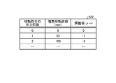
- the floating height range of the substrate S in the floating stage 2 located below the coating section 6 is narrower than the floating height range of the substrate S in the other floating stages 2 .
- the floating height range of the substrate S on the floating stage 2 positioned below the coating section 6 is 30 to 60 ⁇ m.
- the floating height range of the substrate S in the other floating stages 2 is 200 to 2000 ⁇ m.
- the floating stage 2 positioned below the coating section 6 discharges compressed air toward the lower surface of the substrate S, and sucks the air between the substrate S and the floating stage 2, so that the substrate S may be adjusted.
- the first guide rail 3_1 and the second guide rail 3_2 are arranged in the horizontal direction (X-axis direction) and extend along the transport direction (Y-axis direction).
- the first guide rail 3_1 and the second guide rail 3_2 are arranged so as to sandwich the levitation stage 2 in the left-right direction (X-axis direction).
- the first guide rail 3_1 is arranged on the X-axis positive direction side of the levitation stage 2
- the second guide rail 3_2 is arranged on the X-axis negative direction side of the levitation stage 2 .
- the first guide rail 3_1 and the second guide rail 3_2 are made of granite, for example.
- a cross section of the guide rail 3 orthogonal to the transport direction (Y-axis direction) is, for example, rectangular.
- a plurality of holding parts 5 are provided on the first moving part 4_1 and the second moving part 4_2, respectively, and hold the substrate S by suction from below.
- a plurality (here, four) of holding parts 5 suck and hold the four corners of the substrate S from below.
- the substrate S is held at its four corners by a plurality of holders 5 and is transported along the transport direction (Y-axis positive direction) by the first moving part 4_1 and the second moving part 4_2 while being floated by the floating stage 2. be done.
- the applicator 6 is movable along a pair of rails 9 arranged in the Y-axis direction and extending along the X-axis direction.
- a pair of rails 9 are provided, for example, so as to extend rightward with respect to the levitation stage 2 .
- a maintenance section 7 is provided between a pair of rails 9 on the right side of the levitation stage 2 .
- the application unit 6 can move between a position above the maintenance unit 7 and a position where the functional liquid is discharged onto the substrate S. As shown in FIG.
- the application unit 6 is moved in the left-right direction along the pair of rails 9 by a driving device such as a linear motor.
- the plurality of application units 6 may move independently in the left-right direction, or may move together in the left-right direction.
- the maintenance section 7 performs maintenance of the head of the coating section 6 and eliminates or prevents ejection failures of the head of the coating section 6 . Note that the maintenance section 7 may be provided above the levitation stage 2 .
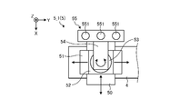
- FIG. 2 is a schematic plan view of the holding portion 5 according to the embodiment.
- FIG. 3 is a schematic side view of the holding part 5 according to the embodiment. 2 and 3 show the first holding portion 5_1 as an example, the configurations of the second holding portion 5_2 to the fourth holding portion 5_4 are also the same as the first holding portion 5_1.
- the holding portion 5 includes a base portion 50, a first adjusting portion 51, a second adjusting portion 52, a rotating portion 53, an arm portion 54, and a suction portion 55.
- the adsorption part 55 adsorbs and holds the substrate S.
- the suction unit 55 includes a plurality of suction pads 551 .
- a plurality of suction pads 551 are provided side by side in the horizontal direction (here, Y-axis direction). Although an example in which the suction unit 55 includes three suction pads 551 is shown here, the number of suction pads 551 is not limited to three.
- the suction unit 55 holds the substrate S by sucking the lower surface of the substrate S with a plurality of suction pads 551 .
- the base part 50 is fixed on the moving part 4 .
- the first adjusting portion 51 is provided on the base portion 50 and is movable on the base portion 50 along the left-right direction (X-axis direction).
- the second adjuster 52 is provided on the first adjuster 51 and is movable on the first adjuster 51 in the front-rear direction (Y-axis direction).
- the rotating portion 53 is provided on the second adjusting portion 52 and is rotatable around the vertical axis (Z-axis).
- the arm portion 54 is a member that extends in the horizontal direction, is supported by the rotating portion 53 at its proximal end, and supports the suction portion 55 at its distal end.
- first adjusting section 51 and the second adjusting section 52 each have a driving section such as a motor, and can move independently.
- the rotating portion 53 is, for example, a bearing, does not have a driving portion, and rotates the adsorption portion 55 so as to follow the movements of the first adjusting portion 51 and the second adjusting portion 52 .
- a drive part may be provided in the rotation part 53.
- the pair of guide rails 3 extends along the front-rear direction (Y-axis direction), which is the transport direction of the substrate S.
- the length of the pair of guide rails 3 in the front-rear direction (Y-axis direction) is approximately 3 to 7 m.
- the pair of guide rails 3 since the pair of guide rails 3 is long, it is difficult to form them completely straight, and there is a possibility that a distortion of, for example, several ⁇ m may occur in the left-right direction (X-axis direction). Similarly, the pair of guide rails 3 may be distorted by several ⁇ m in the vertical direction (Z-axis direction). Moreover, even if the pair of guide rails 3 can be formed straight, there is a possibility that they will be distorted afterward due to environmental changes (for example, temperature changes).
- FIGS. 4 and 5 the guide rails 3 and the holding portion 5 when the pair of guide rails 3 are not distorted are indicated by dashed lines. As indicated by solid lines in FIGS. 4 and 5, in FIGS. 4 and 5, the strain generated in the pair of guide rails 3 is exaggerated for easy understanding.
- the holding portion 5 provided on the first guide rail 3_1 side and the holding portion 5 provided on the second guide rail 3_2 side The distance between is also changed.
- the fourth gap G4 which is the distance between the second holding portion 5_2 and the fourth holding portion 5_4, is is longer than the fourth interval G4.
- the third gap G3 and the fourth gap G4 when the guide rail 3 is distorted are the same as those when the guide rail 3 is not distorted. It may be shorter than the 3rd interval G3 and the 4th interval G4.
- changes in the third gap G3 and the fourth gap G4 can also occur when only one of the pair of guide rails 3 is distorted.
- the substrate processing apparatus 1 includes a measurement system 100.
- the measurement system 100 is an example of a distance measuring unit that measures the distance between adjacent holding portions 5 among the plurality of holding portions 5 .
- the measuring system 100 is also an example of a moving distance measuring unit that measures the moving distances of the first moving unit 4 and the second moving unit 4 along the front-rear direction (Y-axis direction).
- the measurement system 100 measures the distance to the measurement site using laser interferometry.
- the measurement system 100 includes a light projecting unit 110 that projects a laser beam, a light receiving unit 120 that receives the laser light projected from the light projecting unit 110, and light of the laser light from the light projecting unit 110 to the light receiving unit 120. and an optical system 130 arranged on the road.
- the light projecting section 110 includes a light source 111, a plurality of beam splitters 112-115, and a plurality of beam benders 116-118.
- the light source 111 generates laser light.
- a plurality of beam splitters 112 to 115 split the incident laser light into two laser lights at a predetermined splitting ratio.
- a plurality of beam benders 116-118 change the traveling direction of the incident laser light.
- the beam splitter 112 splits the laser light incident from the light source 111 and projects the split light toward the beam splitter 113 and an interferometer 134d, which will be described later.
- the beam splitter 113 splits the laser light incident from the beam splitter 112 and projects the split light toward the beam splitter 114 and the beam bender 116 .
- the beam splitter 114 splits the laser light incident from the beam splitter 113 and projects the split light toward a beam bender 118 and an interferometer 134b, which will be described later.
- the beam splitter 115 splits the laser light incident from a beam bender 116 described later and projects the split light toward a beam bender 117 and a beam splitter 132 described later.
- the beam bender 116 changes the traveling direction of the laser incident from the beam splitter 113 by 90 degrees and projects the light toward the beam splitter 115 .
- the beam bender 117 changes the traveling direction of the laser incident from the beam splitter 115 by 90 degrees and projects the light toward an interferometer 134c described later.
- the beam bender 118 changes the traveling direction of the laser incident from the beam splitter 114 by 90 degrees, and projects the light toward an interferometer 134a, which will be described later.
- the light receiving unit 120 includes a plurality of light receivers 121-126.
- the light receiver 121 receives the laser beam reflected at the measurement site 131a described later
- the light receiver 122 receives the laser light reflected at the measurement site 131b described later
- the light receiver 123 receives the laser light reflected at the measurement site 131c described later.
- the light receiver 124 receives the laser beam reflected at the measurement site 131d described later
- the light receiver 125 receives the laser light reflected at the measurement site 131e described later
- the light receiver 126 receives the laser light reflected at the measurement site 131f described later. receives the laser light reflected at the
- the light projecting unit 110, the light receiving unit 120, and the optical system 130 are arranged along the front-rear direction (Y-axis direction).
- the light receivers 121 to 126 are positioned on the Y-axis positive direction side of the light projecting unit 110 and on the Y-axis negative direction side of the optical system 130. It is located on the Y-axis positive direction side of the system 130 .
- a plurality of measurement sites 131a to 131f are sites irradiated with laser light.
- the plurality of measurement sites 131a to 131f have reflecting surfaces perpendicular to the incident laser light.
- the beam splitter 132 is provided on the first holding portion 5_1.
- the beam splitter 132 splits the laser light incident from the beam splitter 115 and projects the split light toward the interferometer 134 e and the beam bender 133 .
- the beam bender 133 is provided in the second adjuster 52 .
- the beam bender 133 changes the traveling direction of the laser light incident from the beam splitter 132 by 90 degrees and projects the laser light toward the interferometer 134f.
- the plurality of interferometers 134a to 134f for example, split the incident laser light into two laser lights using a beam splitter provided inside. Also, the plurality of interferometers 134a to 134f reflect one of the split laser beams by a reflecting mirror provided inside. The laser light (reference path) reflected by the reflecting mirrors in the interferometers 134a to 134f and the laser light (measurement path) reflected by the measurement sites 131a to 131f are separated by the beam splitters in the interferometers 134a to 134f. They are recombined and enter photodetectors 121-126.
- the measurement system 100 measures the distances to the measurement sites 131a-131f based on the phase difference between the two laser beams obtained by optical signal processing of the laser beams received by the light receivers 121-126.
- the interferometer 134a is arranged at a position separated from the first moving part 4_1 between the light receiver 121 and the measurement site 131a.
- the interferometer 134a splits the laser light projected from the beam bender 118 into two.
- One of the two laser beams split by the interferometer 134a is projected toward the reflecting mirror inside the interferometer 134a, and the other is projected toward the measurement site 131a.
- the laser light recombined in the interferometer 134 a is received by the light receiver 121 .
- the measurement system 100 can obtain the distance from the interferometer 134a to the measurement site 131a, that is, the first moving distance D1, which is the moving distance of the first moving part 4_1. .
- the interferometer 134b is arranged at a position separated from the second moving part 4_2 between the light receiver 122 and the measurement site 131b.
- the interferometer 134b splits the laser light projected from the beam splitter 114 into two.
- One of the two laser beams split by the interferometer 134b is projected toward the reflecting mirror inside the interferometer 134b, and the other is projected toward the measurement site 131b.
- the laser light recombined in the interferometer 134 b is received by the photodetector 122 .
- the measurement system 100 can obtain the distance from the interferometer 134b to the measurement site 131b, that is, the second moving distance D2, which is the moving distance of the second moving part 4_2. .
- the interferometer 134c is provided in the first holding portion 5_1.
- the interferometer 134c splits the laser light projected from the beam bender 117 into two.
- One of the two laser beams split by the interferometer 134c is projected toward the reflecting mirror inside the interferometer 134c, and the other is projected toward the measurement site 131c.
- the laser light recombined in the interferometer 134 c is received by the light receiver 123 .
- the measurement system 100 determines the distance from the interferometer 134c to the measurement site 131b, that is, the distance between the first holding portion 5_1 and the second holding portion 5_2. can be obtained.
- the interferometer 134d is provided in the third holding part 5_3.
- the interferometer 134d splits the laser light projected from the beam splitter 112 into two.
- One of the two laser beams split by the interferometer 134d is projected toward the reflector within the interferometer 134d, and the other is projected toward the measurement site 131d.
- the laser light recombined in the interferometer 134 d is received by the photodetector 124 . Based on the laser light received by the light receiver 124, the measurement system 100 determines the distance from the interferometer 134d to the measurement site 131d, i. can be obtained.
- the interferometer 134e is provided in the first holding portion 5_1.
- a laser beam projected from the beam splitter 115 and split by the beam splitter 132 is incident on the interferometer 134e.
- the interferometer 134e splits the laser light incident from the beam splitter 132 into two.
- One of the two laser beams split by the interferometer 134e is projected toward the reflecting mirror inside the interferometer 134e, and the other is projected toward the measurement site 131e.
- the laser light recombined in the interferometer 134 e is received by the photodetector 125 . Based on the laser light received by the light receiver 125, the measurement system 100 determines the distance from the interferometer 134e to the measurement site 131e, i. can be obtained.
- the interferometer 134f is provided in the second holding portion 5_2.
- a laser beam projected from the beam splitter 132 and having its course changed by the beam bender 133 is incident on the interferometer 134f.
- the interferometer 134f splits the laser light incident from the beam bender 133 into two.
- One of the two laser beams split by the interferometer 134f is projected toward the reflecting mirror inside the interferometer 134f, and the other is projected toward the measurement site 131f.
- the laser light recombined in the interferometer 134f is received by the photodetector 126.
- FIG. Based on the laser light received by the light receiver 126, the measurement system 100 determines the distance from the interferometer 134f to the measurement site 131f, i. can be obtained.
- the interferometers 134c and 134e and the beam splitter 132 provided in the first holding unit 5_1 of the optical system 130 are the first adjustment unit 51 and the second adjustment unit 52. It is provided in the adjustment part located above. With such a configuration, the height positions of the interferometers 134c and 134e and the beam splitter 132 can be brought closer to the height position of the substrate S, so that the first gap G1 and the third gap G3 can be measured with higher accuracy. can be done.
- the rotation of the rotating portion 53 reduces the measurement accuracy of the first gap G1 and the third gap G3. can be suppressed.
- the embodiment shows an example in which the second adjustment section 52 is provided on the first adjustment section 51
- the first adjustment section 51 may be provided on the second adjustment section 52
- interferometers 134 c and 134 e and beam splitter 132 may be provided in first adjustment section 51 .
- the measurement system 100 When measuring the first gap G1 and the third gap G3, the measurement system 100 lifts the stage 151 using the lifting mechanism 150 to move the interferometers 134c and 134e and the beam splitter 132 to the upper surface of the adsorption unit 55 ( That is, it is positioned above the adsorption surface). With this configuration, the height positions of the interferometers 134c and 134e and the beam splitter 132 can be brought closer to the height position of the substrate S, so that the first gap G1 and the third gap G3 can be measured with higher accuracy. be able to.
- the measurement system 100 When measurement is not performed, the measurement system 100 lowers the interferometers 134 c and 134 e and the beam splitter 132 using the elevating mechanism 150 to position them below the upper surface of the adsorption unit 55 . This can prevent the interferometers 134c and 134e and the beam splitter 132 from interfering with the transportation of the substrate S.
- FIG. 7 shows, as an example, the arrangement of the interferometers 134c and 134e and the beam splitter 132 provided in the first holding section 5_1.
- part of the optical system 130 (the beam bender 133 and the interferometer 134f) provided in the second holding part 5_2 and part of the optical system 130 (the interferometer 134d) provided in the third holding part 5_3 are also raised and lowered. It is provided in the second adjusting section 52 via the mechanism 150 .
- the measurement portion 131a provided in the first holding section 5_1 of the optical system 130 is provided below the first adjustment section 51 and the second adjustment section 52.
- the guide rail 3 is distorted in the vertical direction (Z-axis direction)
- the measurement portion 131a is provided in the first adjusting portion 51 or the second adjusting portion 52. Therefore, it is possible to accurately measure the first moving distance D1.
- FIG. 7 shows an example in which the measurement site 131a is provided on the first moving section 4_1.
- the measurement site 131a is provided at a location located below the first adjusting section 51 and the second adjusting section 52 among members other than the first moving section 4_1 that move together with the first moving section 4_1.
- measurement site 131 a may be provided on base portion 50 .
- the measurement site 131a may be provided in the first adjusting section 51 or may be provided in the second adjusting section 52, for example, without being limited to the example described above. By providing the measurement portion 131a at a position close to the substrate S, the first moving distance D1 can be measured with high accuracy.
- the light projecting section 110, the light receivers 121 and 122, the measurement sites 131a and 131b, and the interferometers 134a and 134b are an example of the moving distance measuring section.
- the light projecting unit 110, the light receiving unit 121, the measurement part 131a, and the interferometer 134a are used for first movement distance measurement for measuring the movement distance of the first moving part 4_1 along the front-rear direction (Y-axis direction). This is an example of a part.
- the light projecting section 110, the light receivers 123 to 126, the measurement sites 131c to 131f, the beam splitter 132, the beam bender 133, and the interferometers 134c to 134f measure the distance between the adjacent holding sections 5. It is an example of an interval measurement unit that Specifically, the light projecting unit 110, the light receiving unit 123, the measurement part 131c, and the interferometer 134c are an example of a first distance measuring unit that measures the first distance G1. Further, the light projecting section 110, the light receiver 124, the measurement site 131d, and the interferometer 134d are an example of a second distance measuring section that measures the second distance G2.
- FIG. 8 is a block diagram showing the configuration of the control device 8 according to the embodiment.
- the control device 8 includes a control section 81 and a storage section 82 .
- the control unit 81 is a controller.
- the control unit 81 is realized by executing various programs stored in a storage device inside the control device 8 using the RAM as a work area, for example, by a CPU (Central Processing Unit) or MPU (Micro Processing Unit). be.
- the control unit 81 is a controller, and is implemented by an integrated circuit such as an ASIC (Application Specific Integrated Circuit) or an FPGA (Field Programmable Gate Array).
- the control unit 81 includes a measurement processing unit 811, a change processing unit 812, and a transport processing unit 813, and implements or executes processing functions and actions described below.
- the storage unit 82 is implemented by, for example, a semiconductor memory device such as RAM (Random Access Memory) or flash memory, or a storage device such as a hard disk or optical disk. As shown in FIG. 8 , the storage unit 82 stores transport information 821 , first moving unit adjustment information 822 and second moving unit adjustment information 823 . The storage unit 82 also stores first holding portion adjustment information 824 , second holding portion adjustment information 825 , third holding portion adjustment information 826 , and fourth holding portion adjustment information 827 .
- a semiconductor memory device such as RAM (Random Access Memory) or flash memory
- FIG. 8 the storage unit 82 stores transport information 821 , first moving unit adjustment information 822 and second moving unit adjustment information 823 .
- the storage unit 82 also stores first holding portion adjustment information 824 , second holding portion adjustment information 825 , third holding portion adjustment information 826 , and fourth holding portion adjustment information 827 .
- the transport information 821 is information indicating the amount of movement instructed to the moving part 4 and the holding part 5 at each point on the pair of guide rails 3 .
- Each point on the pair of guide rails 3 is, for example, the distance from the starting point of the transport path of the substrate S (the movement distance of the moving part 4 when it is assumed that the pair of guide rails 3 are not distorted, hereinafter referred to as "ideal movement distance”).
- a movement command for the moving part 4 and the holding part 5 is output, for example, every 50 mm of the ideal movement distance.
- the transport information 821 is associated with the amount of movement instructed to the first moving unit 4_1 and the second moving unit 4_2 for each ideal moving distance of 50 mm.
- 50 mm may be associated with each ideal movement distance of 50 mm as a movement amount instructed to the first moving section 4_1 and the second moving section 4_2.
- the first moving part 4_1 and the second moving part 4_2 move 50 mm on the guide rail each time a movement instruction is received.
- the transport information 821 may be associated with, for example, the amount of movement in consideration of the distortion of the pair of guide rails 3, which is obtained based on prior measurements using a laser interferometer or the like. For example, when a movement command for a movement amount of 50 mm was output to the first moving unit 4_1 at a point with an ideal movement distance of 100 mm, it was found from previous measurements that the point actually reached was 149 mm. Suppose In this case, the transport information 821 may be associated with a movement amount of 51 mm for an ideal movement distance of 100 mm. By outputting such a movement command and moving the first moving part 4_1 and the second moving part 4_2 by 51 mm, the first moving part 4_1 and the second moving part 4_2 can be made to reach the point of 150 mm.
- the information associated with the movement amount in the transport information 821 is the ideal movement distance
- the information associated with the movement amount in the transport information 821 is the movement command for the moving unit 4 and the holding unit 5. It may be the number of outputs. That is, the transport information 821 may be information in which the movement amount included in the movement command is associated with the number of times the movement command is output to the moving unit 4 and the holding unit 5 .
- the transport information 821 is associated with the movement amount instructed to the first holding part 5_1 to the fourth holding part 5_4 for each ideal movement distance of 50 mm, for example.
- the transport information 821 for each holding unit 5 is the amount of movement of the first adjustment unit 51 (hereinafter referred to as “X movement amount”) and the second adjustment with respect to the ideal movement distance (or the number of times the movement command is output). It is information that associates the amount of movement of the unit 52 (hereinafter referred to as "Y movement amount").
- X movement amount the amount of movement of the first adjustment unit 51
- Y movement amount the transport information 821 for each holding portion 5 considers the distortion of the pair of guide rails 3 based on, for example, prior measurements.
- the transport information 821 for each holding portion 5 may not consider the distortion of the pair of guide rails 3 .
- "0" is associated with the ideal movement distance (or the number of times the movement command is output) as the X movement amount and the Y movement amount.
- Each of the adjustment information 822 to 827 including the first moving part adjustment information 822 is information for adjusting the movement amount associated with the transport information 821 .
- the first moving part adjustment information 822 is information indicating an adjustment value for adjusting the movement amount included in the movement command output to the first moving part 4_1 at each point on the first guide rail 3_1.
- the second moving part adjustment information 823 is information indicating an adjustment value for adjusting the amount of movement included in the movement command output to the second moving part 4_2 at each point on the second guide rail 3_2. be.
- FIG. 9 is a diagram showing an example of first moving unit adjustment information 822 according to the embodiment.
- the first moving part adjustment information 822 is information in which the item "number of output of movement commands", the item “ideal movement distance”, and the item “adjustment value” are associated with each other.
- the number of times a move command is output to the first mover 4_1 is stored in the "number of times move command is output" item.
- the first movement distance after the movement command is output the number of times stored in the corresponding "output number of movement commands"
- the ideal moving distance of the part 4_1 is stored.
- the “adjustment value” item stores the adjustment value of the movement amount stored in the transport information 821 for the first moving unit 4_1.
- the ideal movement distance "50 (mm)” and the adjustment value "-1 ( ⁇ m)" are associated with the number of times the movement command is output “1 (times)". This indicates that the ideal moving distance of the first moving section 4_1 when the first moving command is output to the first moving section 4_1 is "50 (mm)". Further, the transport information 821 indicates that the movement amount associated with the first movement command for the first moving section 4_1 is adjusted by "-1 ( ⁇ m)".
- the positive and negative values of the “adjustment value ( ⁇ m)” shown in FIG. 9 are “+” when adjusting in the positive direction of the Y-axis and “-” when adjusting in the negative direction of the Y-axis.
- the first holding portion adjustment information 824 is information indicating an adjustment value for adjusting the movement amount included in the movement command output to the first holding portion 5_1 at each point on the first guide rail 3_1.
- the second holding portion adjustment information 825 is information indicating an adjustment value for adjusting the amount of movement included in the movement command output to the second holding portion 5_2 at each point on the first guide rail 3_1.
- the third holding portion adjustment information 826 is information indicating an adjustment value for adjusting the movement amount included in the movement command output to the third holding portion 5_3 at each point on the second guide rail 3_2. be.
- the fourth holding portion adjustment information 827 is information indicating an adjustment value for adjusting the movement amount included in the movement command output to the fourth holding portion 5_4 at each point on the second guide rail 3_2. be.
- FIG. 10 is a diagram illustrating an example of first holding unit adjustment information 824 according to the embodiment.
- the first holding unit adjustment information 824 includes an item of "number of output of movement commands", an item of "ideal movement distance”, an item of "X adjustment value”, and an item of "Y adjustment value”. This is associated information.
- the number of times the movement command is output to the first adjustment section 51 and the second adjustment section 52 included in the first holding section 5_1 is stored in the "output number of movement commands" item.
- the "ideal movement distance” item when it is assumed that the pair of guide rails 3 are not distorted, the first movement distance after the movement command is output the number of times stored in the corresponding "output number of movement commands"
- the ideal moving distance of the part 4_1 is stored.
- the "X adjustment value” item stores a value for adjusting the X movement amount stored in the transport information 821 for the first holding unit 5_1.
- the "Y adjustment value” item stores a value for adjusting the Y movement amount stored in the transport information 821 for the first holding unit 5_1.
- the ideal movement distance is 50 (mm)
- the X adjustment value is 0 ( ⁇ m)
- the Y adjustment value is 3 ( ⁇ m) for the number of output movement commands of 1 (times). )” is associated.
- the ideal moving distance of the first moving part 4_1 when the first moving command is output to the first holding part 5_1 is "50 (mm)”.
- the X movement amount associated with the first movement command to the first holding unit 5_1 is adjusted to "0 ( ⁇ m)”
- the Y movement amount is adjusted to "3 ( ⁇ m)”. ing.
- the control part 81 adjusts the adjusting part of each holding part 5 so that the measurement result by the measuring system 100 is constant. It controls and adjusts the position of the adsorption part 55 with respect to the moving part 4 .
- the control section 81 includes a measurement processing section 811 , a change processing section 812 and a transport processing section 813 .
- the measurement processing unit 811 performs measurement by the measurement system 100 while moving the first moving unit 4_1 and the second moving unit 4_2 along the pair of guide rails 3 . As a result, the information of the first movement distance D1, the first gap G1, the third gap G3, and the fourth gap G4 at each point on the first guide rail 3_1 and the second movement distance at each point on the second guide rail 3_2 are obtained. Information of the distance D2 and the second spacing G2 is obtained.
- the measurement processing by the measurement processing unit 811 is performed while the substrates S are not held by the plurality of holding units 5 .
- the change processing unit 812 changes the first moving unit adjustment information 822 stored in the storage unit 82 based on the measurement result of the first moving distance D1 measured by the measurement system 100 in the measurement processing by the measurement processing unit 811. Similarly, the change processing unit 812 changes the second movement unit adjustment information 823 stored in the storage unit 82 based on the measurement result of the second movement distance D2 measured by the measurement system 100 in the measurement processing by the measurement processing unit 811. change.
- the change processing unit 812 for each movement command to the first moving part 4_1 (every time the first moving part 4_1 moves according to the movement command), changes the first moving part 4_1 after the first moving part 4_1 moves according to the movement command. It is determined whether or not the distance D1 has deviated from the ideal moving distance. Then, when it is determined that the first moving distance D1 deviates from the ideal moving distance, the change processing unit 812 adjusts the movement in the first moving part adjustment information 822 so that the first moving distance D1 matches the ideal moving distance. Change the adjustment value associated with the command. For example, assume that the first moving distance D1 after the first moving part 4_1 moves according to the third movement command is deviated from the ideal moving distance by -1 ⁇ m. In this case, the change processing unit 812 adds 1 ⁇ m to the adjustment value associated with the third movement command in the first movement unit adjustment information 822 .
- the change processing unit 812 performs the first holding unit adjustment stored in the storage unit 82 based on the measurement results of the first interval G1 to the fourth interval G4 measured by the measurement system 100 in the measurement processing by the measurement processing unit 811.
- Information 824 to fourth holding unit adjustment information 827 are changed.
- the change processing unit 812 determines whether the first interval G1 has changed from the first specified value for each point on the first guide rail 3_1.
- “at each point on the first guide rail 3_1” can be rephrased as “each move command to the first moving part 4_1” or "each time the first moving part 4_1 moves according to the move command”.
- the first specified value is the value obtained when it is assumed that each of the suction portions 55 of the first holding portion 5_1 and the suction portions 55 of the second holding portion 5_2 is correctly sucking and holding the substrate S at a prescribed position. This is the ideal value for the first interval G1. If the first guide rail 3_1 is straight without being distorted, the first gap G1 is maintained at the first specified value from the start point to the end point of the substrate S transport path.
- the change processing unit 812 changes the first holding unit adjustment information 824 or the second holding unit adjustment information 825 so that the first interval G1 at that point matches, for example, the first specified value in the next transportation process. change.
- the change processing unit 812 changes the first holding unit adjustment information 824 . Specifically, the change processing unit 812 changes the Y adjustment value corresponding to the point at which the first interval G1 has changed (the number of times the movement command is output) in the first holding unit adjustment information 824 . For example, assume that the first gap G1 changes from the first specified value by "-1 ⁇ m" after the first moving part 4_1 moves according to the second movement command. In this case, the change processing unit 812 subtracts 1 ⁇ m from the Y adjustment value “4 ( ⁇ m)” associated with the movement command output count “2” in the first holding unit adjustment information 824 to obtain “3 ( ⁇ m)”. )”.
- the change processing unit 812 may change the Y adjustment value of the second holding unit adjustment information 825 .
- the change processing unit 812 changes the position at the one point in the transport process after the measurement process.
- the amount of movement of the first adjustment portion 51, which is one of the first holding portion 5_1 and the second holding portion 5_2, at the one point is adjusted so that the first gap G1 at .theta.
- the first distance G1 at the one point can be maintained at the first predetermined value. That is, the relative positions of the first holding portion 5_1 and the second holding portion 5_2 at the one point can be maintained.
- the change processing unit 812 determines whether or not the second interval G2 has changed from the second specified value for each point on the second guide rail 3_2.
- the second specified value is the second specified value when it is assumed that each of the adsorption portions 55 of the third holding portion 5_3 and the adsorption portions 55 of the fourth holding portion 5_4 correctly adsorbs and holds the substrate S at a specified position. This is the ideal value for the interval G2.
- the change processing unit 812 changes the third holding unit adjustment information 826 or the fourth holding unit adjustment information 827 so that the second interval G2 at that point matches the second specified value in the next transportation process, for example. do.
- the change processing unit 812 changes the third holding unit adjustment information 826 .
- the change processing unit 812 changes the Y adjustment value corresponding to the point (the number of times the movement command is output) at which the second interval G2 changes in the third holding unit adjustment information 826 .
- the change processing unit 812 may change the Y adjustment value of the fourth holding unit adjustment information 827 .
- the change processing unit 812 determines whether or not the third interval G3 has changed from the third specified value for each point on the first guide rail 3_1.
- the third specified value is the third specified value when it is assumed that each of the suction portions 55 of the first holding portion 5_1 and the suction portions 55 of the third holding portion 5_3 is correctly sucking and holding the substrate S at a prescribed position. This is the ideal value for the interval G3.
- the change processing unit 812 changes the first holding unit adjustment information 824 or the third holding unit adjustment information 826 so that the third interval G3 at that point matches the third specified value in the next transportation process, for example. do.
- the change processing unit 812 changes the first holding unit adjustment information 824 .
- the change processing unit 812 changes the X adjustment value corresponding to the point (the number of times the movement command is output) at which the third interval G3 has changed in the first holding unit adjustment information 824 .
- the change processing unit 812 may change the X adjustment value of the third holding unit adjustment information 826 .
- the change processing unit 812 adds 1 ⁇ m to the X adjustment value “5 ( ⁇ m)” associated with the movement command output count “2” in the first holding unit adjustment information 824 to obtain “6 ( ⁇ m)”. )”.
- the second adjustment part 52 of the first holding part 5_1 is The amount of movement included in the output movement command is adjusted.
- the change processing unit 812 may change the X adjustment value of the third holding unit adjustment information 826 .
- the change processing unit 812 changes the position at the one point in the transport process after the measurement process.
- the amount of movement of the second adjusting portion 52, which is one of the first holding portion 5_1 and the third holding portion 5_3, at the one point is adjusted so that the third gap G3 at the point coincides with the third specified value.
- the third gap G3 at the one point can be maintained at the third default value. That is, the relative positions of the first holding portion 5_1 and the third holding portion 5_3 at the one point can be maintained.
- the change processing unit 812 determines whether the fourth interval G4 has changed from the fourth specified value for each point on the first guide rail 3_1.
- the fourth specified value is the fourth specified value when it is assumed that each of the adsorption portions 55 of the second holding portion 5_2 and the adsorption portions 55 of the fourth holding portion 5_4 correctly adsorbs and holds the substrate S at a specified position. This is the ideal value for the interval G4.
- the change processing unit 812 changes the second holding unit adjustment information 825 or the fourth holding unit adjustment information 827 so that the fourth interval G4 at that point matches the fourth specified value in the next transportation process, for example. do.
- the change processing unit 812 changes the second holding unit adjustment information 825 .
- the change processing unit 812 changes the X adjustment value corresponding to the point (the number of times the movement command is output) at which the fourth interval G4 changes in the second holding unit adjustment information 825 .
- the change processing unit 812 may change the X adjustment value of the fourth holding unit adjustment information 827 .
- the transport processing unit 813 controls the first moving unit 4_1 using the transport information 821 and the first moving unit adjustment information 822 to determine the amount of movement of the first moving unit 4_1 at each point on the first guide rail 3_1. adjust. Specifically, the transport processing unit 813 adjusts the movement amount of the first moving unit 4_1 stored in the transport information 821 using the adjustment value stored in the first moving unit adjustment information 822 . Then, the transport processing unit 813 outputs a movement command including the adjusted movement amount to the first moving unit 4_1.
- the transport processing unit 813 controls the second moving unit 4_2 using the transport information 821 and the second moving unit adjustment information 823 to move the second moving unit 4_2 at each point on the second guide rail 3_2. Adjust quantity. Specifically, the transport processing unit 813 adjusts the movement amount of the second moving unit 4_2 stored in the transport information 821 using the adjustment value stored in the second moving unit adjustment information 823 . Then, the transport processing section 813 outputs a movement command including the adjusted movement amount to the second movement section 4_2.
- the transport processing unit 813 uses the transport information 821 and the first holding unit adjustment information 824 to control the second adjusting unit 52 of the first holding unit 5_1, so that each point on the first guide rail 3_1 Adjust the amount of movement of the second adjuster 52 . Specifically, the transport processing unit 813 adjusts the movement amount of the second adjustment unit 52 stored in the transport information 821 using the adjustment value stored in the first holding unit adjustment information 824 . Then, the transport processing unit 813 outputs a movement command including the adjusted movement amount to the second adjustment unit 52 of the first holding unit 5_1.
- the transport processing unit 813 uses the transport information 821 and the second holding unit adjustment information 825 to control the first adjusting unit 51 and the second adjusting unit 52 of the second holding unit 5_2. Further, the transport processing unit 813 uses the transport information 821 and the third holding unit adjustment information 826 to control the first adjustment unit 51 and the second adjustment unit 52 of the third holding unit 5_3. Further, the transport processing unit 813 uses the transport information 821 and the fourth holding unit adjustment information 827 to control the first adjusting unit 51 and the second adjusting unit 52 of the fourth holding unit 5_4.
- the transport processing unit 813 moves the first moving unit 4_1 and the second moving unit 4_2 along the pair of guide rails 3
- the first adjusting unit 51 moves on the basis of the measurement results obtained by the measurement process.
- the second adjuster 52 to adjust the position of the suction part 55 at each point of the pair of guide rails.
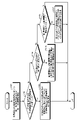
- FIG. 11 is a flow chart showing procedures of the measurement process and the change process among the processes executed by the substrate processing apparatus 1 according to the embodiment. Each process shown in FIG. 11 is executed under the control of the control device 8 .
- the substrate processing apparatus 1 performs measurement processing. Specifically, the control unit 81 performs measurement by the measurement system 100 while moving the moving unit 4 and the holding unit 5 (step S101). At this time, the control section 81 moves the first moving section 4_1 by controlling the first moving section 4_1 using the transport information 821 and the first moving section adjustment information 822 . Further, the control section 81 moves the second moving section 4_2 by controlling the second moving section 4_2 using the transport information 821 and the second moving section adjustment information 823 . Further, the control unit 81 uses the transport information 821 and the first holding unit adjustment information 824 to move the first holding unit 5_1, and uses the transport information 821 and the second holding unit adjustment information 825 to move the second holding unit 5_2. move. Further, the control unit 81 uses the transport information 821 and the third holding unit adjustment information 826 to move the third holding unit 5_3, and uses the transport information 821 and the fourth holding unit adjustment information 827 to move the fourth holding unit 5_4. move.
- the control unit 81 uses the measurement system 100 to determine the first moving distance D1, the second moving distance D2, and the A first interval G1 to a fourth interval G4 are measured.
- control unit 81 determines whether or not the first moving distance D1 or the second moving distance D2 has changed from the ideal moving distance (step S102).
- step S102 When it is determined in step S102 that the first movement distance D1 or the second movement distance D2 has changed from the ideal movement distance (step S102; Yes), the control unit 81 determines that the first movement distance D1 or the second movement distance D2 is The adjustment value of the first moving unit 4_1 or the second moving unit 4_2 is changed so as to match the ideal moving distance (step S103).
Abstract
Selon un mode de réalisation, la présente invention concerne un dispositif de transfert de substrat comprenant une paire de rails de guidage, une première unité de déplacement, une seconde unité de déplacement, une pluralité de pièces de maintien, une unité de mesure d'espace, et une unité de commande. La paire de rails de guidage est alignée dans un premier sens et s'étend dans un second sens qui est orthogonal au premier sens. La pluralité des pièces de maintien sont chacune disposées sur la première unité de déplacement et la seconde unité de déplacement et maintiennent un substrat, depuis son fond, par aspiration. L'unité de mesure d'espace mesure la distance entre les pièces de maintien qui sont, parmi la pluralité des pièces de maintien, adjacentes l'une à l'autre. L'unité de commande commande la première unité de déplacement, la seconde unité de déplacement, et la pluralité des pièces de maintien. La pluralité des pièces de maintien comprend une unité d'aspiration pour maintenir le substrat par aspiration et une unité d'ajustement pour ajuster la position de l'unité d'aspiration. L'unité de commande transfère le substrat tout en commandant à l'unité d'ajustement d'ajuster la position de l'unité d'aspiration de sorte que les résultats de mesure par l'unité de mesure d'espace demeurent constants lorsque la première unité de déplacement et la seconde unité de déplacement se déplacent le long de la paire des rails de guidage.
Priority Applications (1)
| Application Number | Priority Date | Filing Date | Title |
|---|---|---|---|
| JP2023509013A JPWO2022202396A1 (fr) | 2021-03-25 | 2022-03-11 |
Applications Claiming Priority (2)
| Application Number | Priority Date | Filing Date | Title |
|---|---|---|---|
| JP2021-051493 | 2021-03-25 | ||
| JP2021051493 | 2021-03-25 |
Publications (1)
| Publication Number | Publication Date |
|---|---|
| WO2022202396A1 true WO2022202396A1 (fr) | 2022-09-29 |
Family
ID=83397111
Family Applications (1)
| Application Number | Title | Priority Date | Filing Date |
|---|---|---|---|
| PCT/JP2022/010829 WO2022202396A1 (fr) | 2021-03-25 | 2022-03-11 | Dispositif de transfert de substrat, dispositif de traitement de revêtement, procédé de transfert de substrat, et programme de transfert de substrat |
Country Status (3)
| Country | Link |
|---|---|
| JP (1) | JPWO2022202396A1 (fr) |
| TW (1) | TW202301531A (fr) |
| WO (1) | WO2022202396A1 (fr) |
Citations (4)
| Publication number | Priority date | Publication date | Assignee | Title |
|---|---|---|---|---|
| JP2005132626A (ja) * | 2003-10-06 | 2005-05-26 | Sumitomo Heavy Ind Ltd | 搬送装置、塗布システム、及び検査システム |
| JP2008302487A (ja) * | 2007-06-11 | 2008-12-18 | Olympus Corp | 基板吸着装置及び基板搬送装置並びに外観検査装置 |
| JP2009117571A (ja) * | 2007-11-06 | 2009-05-28 | Tokyo Electron Ltd | 基板処理装置及び塗布装置及び塗布方法 |
| JP2020054973A (ja) * | 2018-10-04 | 2020-04-09 | 東京エレクトロン株式会社 | 基板処理装置および基板処理方法 |
-
2022
- 2022-03-11 TW TW111108935A patent/TW202301531A/zh unknown
- 2022-03-11 WO PCT/JP2022/010829 patent/WO2022202396A1/fr active Application Filing
- 2022-03-11 JP JP2023509013A patent/JPWO2022202396A1/ja active Pending
Patent Citations (4)
| Publication number | Priority date | Publication date | Assignee | Title |
|---|---|---|---|---|
| JP2005132626A (ja) * | 2003-10-06 | 2005-05-26 | Sumitomo Heavy Ind Ltd | 搬送装置、塗布システム、及び検査システム |
| JP2008302487A (ja) * | 2007-06-11 | 2008-12-18 | Olympus Corp | 基板吸着装置及び基板搬送装置並びに外観検査装置 |
| JP2009117571A (ja) * | 2007-11-06 | 2009-05-28 | Tokyo Electron Ltd | 基板処理装置及び塗布装置及び塗布方法 |
| JP2020054973A (ja) * | 2018-10-04 | 2020-04-09 | 東京エレクトロン株式会社 | 基板処理装置および基板処理方法 |
Also Published As
| Publication number | Publication date |
|---|---|
| TW202301531A (zh) | 2023-01-01 |
| JPWO2022202396A1 (fr) | 2022-09-29 |
Similar Documents
| Publication | Publication Date | Title |
|---|---|---|
| US20080012189A1 (en) | System for structuring solar modules | |
| JP4426276B2 (ja) | 搬送装置、塗布システム、及び検査システム | |
| US7009683B2 (en) | Exposure apparatus | |
| CN113571445A (zh) | 引导传输路径校正 | |
| US8496462B2 (en) | Imprint apparatus and article manufacturing method | |
| JP2008147291A (ja) | 基板支持装置、基板支持方法、基板加工装置、基板加工方法、表示装置構成部材の製造方法 | |
| KR101468486B1 (ko) | 묘화 장치 및 방법 | |
| JP5303129B2 (ja) | 塗布装置及び塗布方法 | |
| WO2022202396A1 (fr) | Dispositif de transfert de substrat, dispositif de traitement de revêtement, procédé de transfert de substrat, et programme de transfert de substrat | |
| JP5188759B2 (ja) | 塗布装置及び塗布方法 | |
| KR20200067738A (ko) | 스테이지 장치 및 하전 입자선 장치 | |
| JP2013131577A (ja) | インプリント装置、インプリント方法およびデバイスの製造方法 | |
| KR101394312B1 (ko) | 웨이퍼 정렬장치 | |
| JP4982292B2 (ja) | 塗布装置及び塗布方法 | |
| US20230347667A1 (en) | Substrate positioning for deposition machine | |
| JP3634530B2 (ja) | 位置決め装置および露光装置 | |
| JP5349770B2 (ja) | 塗布装置及び塗布方法 | |
| JP6333065B2 (ja) | 塗布装置 | |
| JP4291313B2 (ja) | ヘッド作動制御装置及び制御方法及びステージ装置 | |
| KR20200038862A (ko) | 기판 처리 장치 및 기판 처리 방법 | |
| KR20220001471A (ko) | 기판 처리 장치 및 기판 처리 방법 | |
| JP5280064B2 (ja) | 電子ビーム描画装置 | |
| KR20180011728A (ko) | 기능액 토출 장치 및 기능액 토출 위치 보정 방법 | |
| WO2022210940A1 (fr) | Dispositif de transport de substrat, dispositif de traitement de revêtement et procédé de transport de substrat | |
| KR20220121697A (ko) | 묘화 장치, 묘화 방법 및 기록 매체에 기록된 프로그램 |
Legal Events
| Date | Code | Title | Description |
|---|---|---|---|
| 121 | Ep: the epo has been informed by wipo that ep was designated in this application |
Ref document number: 22775188 Country of ref document: EP Kind code of ref document: A1 |
|
| WWE | Wipo information: entry into national phase |
Ref document number: 2023509013 Country of ref document: JP |
|
| NENP | Non-entry into the national phase |
Ref country code: DE |
|
| 122 | Ep: pct application non-entry in european phase |
Ref document number: 22775188 Country of ref document: EP Kind code of ref document: A1 |