WO2022196344A1 - 保持器および玉軸受 - Google Patents
保持器および玉軸受 Download PDFInfo
- Publication number
- WO2022196344A1 WO2022196344A1 PCT/JP2022/008600 JP2022008600W WO2022196344A1 WO 2022196344 A1 WO2022196344 A1 WO 2022196344A1 JP 2022008600 W JP2022008600 W JP 2022008600W WO 2022196344 A1 WO2022196344 A1 WO 2022196344A1
- Authority
- WO
- WIPO (PCT)
- Prior art keywords
- grease
- synthetic resin
- prevention wall
- crown
- Prior art date
- Legal status (The legal status is an assumption and is not a legal conclusion. Google has not performed a legal analysis and makes no representation as to the accuracy of the status listed.)
- Ceased
Links
Images


Classifications
-
- F—MECHANICAL ENGINEERING; LIGHTING; HEATING; WEAPONS; BLASTING
- F16—ENGINEERING ELEMENTS AND UNITS; GENERAL MEASURES FOR PRODUCING AND MAINTAINING EFFECTIVE FUNCTIONING OF MACHINES OR INSTALLATIONS; THERMAL INSULATION IN GENERAL
- F16C—SHAFTS; FLEXIBLE SHAFTS; ELEMENTS OR CRANKSHAFT MECHANISMS; ROTARY BODIES OTHER THAN GEARING ELEMENTS; BEARINGS
- F16C19/00—Bearings with rolling contact, for exclusively rotary movement
- F16C19/02—Bearings with rolling contact, for exclusively rotary movement with bearing balls essentially of the same size in one or more circular rows
- F16C19/14—Bearings with rolling contact, for exclusively rotary movement with bearing balls essentially of the same size in one or more circular rows for both radial and axial load
- F16C19/16—Bearings with rolling contact, for exclusively rotary movement with bearing balls essentially of the same size in one or more circular rows for both radial and axial load with a single row of balls
-
- F—MECHANICAL ENGINEERING; LIGHTING; HEATING; WEAPONS; BLASTING
- F16—ENGINEERING ELEMENTS AND UNITS; GENERAL MEASURES FOR PRODUCING AND MAINTAINING EFFECTIVE FUNCTIONING OF MACHINES OR INSTALLATIONS; THERMAL INSULATION IN GENERAL
- F16C—SHAFTS; FLEXIBLE SHAFTS; ELEMENTS OR CRANKSHAFT MECHANISMS; ROTARY BODIES OTHER THAN GEARING ELEMENTS; BEARINGS
- F16C33/00—Parts of bearings; Special methods for making bearings or parts thereof
- F16C33/30—Parts of ball or roller bearings
- F16C33/38—Ball cages
- F16C33/41—Ball cages comb-shaped
-
- F—MECHANICAL ENGINEERING; LIGHTING; HEATING; WEAPONS; BLASTING
- F16—ENGINEERING ELEMENTS AND UNITS; GENERAL MEASURES FOR PRODUCING AND MAINTAINING EFFECTIVE FUNCTIONING OF MACHINES OR INSTALLATIONS; THERMAL INSULATION IN GENERAL
- F16C—SHAFTS; FLEXIBLE SHAFTS; ELEMENTS OR CRANKSHAFT MECHANISMS; ROTARY BODIES OTHER THAN GEARING ELEMENTS; BEARINGS
- F16C33/00—Parts of bearings; Special methods for making bearings or parts thereof
- F16C33/30—Parts of ball or roller bearings
- F16C33/66—Special parts or details in view of lubrication
Definitions
- the present invention relates to a retainer suitable for miniature ball bearings and small-diameter ball bearings that require low torque, low torque fluctuation, and grease lubricity, and a ball bearing using this retainer.
- a crown-shaped one that is integrally molded from resin.
- a pair of retaining claws are arranged at regular intervals in the circumferential direction on the upper surface of an annular retainer body, and a pocket for retaining balls is formed between the pair of retaining claws.
- a flat portion is formed between the holding claws where the back surfaces of the two continuous pockets are opposed to each other, and serves as a reference surface for raising the holding claws.
- a grease pocket is formed by this flat portion and the back surface of the holding claw.
- the grease is filled in the flat portion while avoiding the balls. This is to prevent rises and fluctuations in rotational torque caused by grease getting caught between the balls and the raceway surfaces and between the balls and the inner circumferential surfaces of the pockets during operation.
- a grease-scattering prevention wall is provided between the holding claws of the pockets facing each other on the back surface.
- a slit is provided in the center of the wall in the circumferential direction. Since the grease-splash prevention wall has slits, the amount of base oil required for lubrication from the enclosed grease can flow out to the inner diameter side of the cage, and it is said that lubricity can be maintained for a long period of time.
- a grease-splashing prevention wall is provided between holding claws facing each other on the back surface of the pocket, and slits are formed at both ends of the wall.
- the present invention has been made in view of the above circumstances, and is capable of suppressing the scattering of grease from grease pockets.
- a cage and a ball bearing that can reduce torque increases and torque fluctuations caused by entering between the cage pocket and the cage pocket, and prevent grease from adhering to the inner and outer rings during grease filling. is intended to provide
- the present invention relates to a synthetic resin crown-shaped retainer in which a plurality of pockets in which balls are fitted are formed along the circumferential direction between a pair of retaining claws extending axially from an annular base, the retainer comprising: Each of the holding claws has a rear surface facing the outer side in the circumferential direction of the pocket, the rear surface of the first holding claw of the first pocket, and the second pocket adjacent to the first pocket.
- a grease receiving surface is formed between the first holding claw and the second holding claw, and a first grease receiving surface is formed on the inner peripheral side of the grease receiving surface.
- An inner grease scattering prevention wall connected to the holding claw is formed along the circumferential direction, and an outer grease scattering prevention wall connected to the second holding claw is formed circumferentially on the outer peripheral side of the grease receiving surface. At least part of the inner grease-splashing prevention wall forms an inner slit spaced apart from the second holding claw, and at least part of the outer grease-spattering prevention wall is spaced from the first holding claw It is a crown-shaped retainer made of synthetic resin that forms an outer slit spaced apart from the .
- the inner grease-spattering prevention wall and the outer grease-spattering prevention wall without slits in the intermediate portion are provided on the inner and outer peripheral sides of the retainer. It is possible to suppress the grease from leaking out of the grease storage portion when filling the grease storage portion formed with the outer grease scattering prevention wall with the grease.
- the outer grease splattering prevention wall prevents grease from splattering toward the outer ring due to centrifugal force during high-speed rotation. Since the slits are provided, an appropriate amount of lubricating oil is supplied to the balls and the raceway surface from the slits without spattering the grease from the grease storage portion even when rotating at high speed.
- the present invention it is possible to reduce the torque increase and torque fluctuation caused by the grease entering between the ball and the raceway surface or between the ball and the pocket even when the grease is oscillating or rotating at high speed. , it is possible to suppress adhesion of grease to the inner ring and the outer ring at the time of filling with grease.
- the present invention also provides a ball bearing comprising an inner ring, an outer ring, a plurality of balls arranged between the inner ring and the outer ring, and a retainer configured as described above for holding the balls.
- the present invention it is possible to reduce torque increase and torque fluctuation caused by grease entering between the ball and the raceway surface or between the ball and the cage pocket even if the ball is oscillating or rotating at high speed. In addition, it is possible to suppress adhesion of grease to the inner ring and the outer ring when filling with grease.
- FIG. 5 is a graph showing the average value of rotational torque measured when the number of revolutions is changed for ball bearings of an embodiment of the present invention and a comparative example
- FIG. 4 is a graph showing temporal changes in rotational torque of ball bearings of an embodiment of the present invention and a comparative example when the rotational speed is 15,000 rpm.
- the cage 10 of the present invention includes a ring-shaped base portion 11 and a pair of holding claws 12 extending axially upward from the base portion 11. , a crown-shaped retainer made of synthetic resin in which a plurality of pockets 14 in which balls 13 are fitted are formed along the circumferential direction.
- the inner periphery of the pocket 14 has a spherical shape with a slightly larger diameter than the outer diameter of the ball 13 .
- thermoplastic resin such as polyamide (nylon 66, nylon 46, etc.), polyacetal, or polyetheretherketone (PEEK) reinforced with glass fiber or carbon fiber can be used. Then, such a synthetic resin is preferably molded into the retainer 10 by injection molding suitable for mass production.
- Each of the pair of holding claws 12 forming the pocket 14 has a back surface 12a facing the outer side of the pocket 14 in the circumferential direction.
- the back surface 12a is spherical like the inner circumference of the pocket 14.
- one pocket 14 and one holding claw 12 are called a first pocket 141 and a first holding claw 121
- the adjacent pocket 14 is called a second pocket 142 and a second holding claw 122. Used for explanation.
- the rear surface 12a of the first holding claw 121 of the first pocket 141 faces the rear surface of the second holding claw 122 of the second pocket 142 located next to the first pocket 141 in the circumferential direction.
- a flat portion (grease receiving surface) 15 is formed between the first holding claw 121 of the first pocket 141 and the second holding claw 122 of the second pocket 142 .
- the axial position of the flat portion 15 is substantially the same as the axial positions of the centers of the first and second pockets 141 and 142 .
- An inner grease scattering prevention wall 16 connected to the first holding claw 121 of the first pocket 141 is formed on the inner peripheral side of the flat portion 15 along the circumferential direction.
- an outer grease scattering prevention wall 17 connected to the second holding claws 122 of the second pocket 142 is formed on the outer peripheral side of the flat portion 15 along the circumferential direction.
- a grease reservoir 18 is formed by the flat portion 15 , the inner grease-scattering prevention wall 16 , and the outer grease-scattering prevention wall 17 .
- the inner grease scattering prevention wall 16 is separated from the second holding claw 122 to form an inner slit 16a
- the outer grease scattering prevention wall 17 is separated from the first holding claw 121 to form an outer slit 17a.
- the inner and outer slits 16a and 17a serve as outlets for supplying the lubricating oil eluted from the grease filled in the grease reservoir 18 to the balls 23 and the raceway surface.
- the center of the flat portion 15 is aimed. to dispense the grease from the dispenser.
- the inner grease scattering prevention wall 16 and the outer grease scattering prevention wall 17 having no slits in the middle are provided on the inner and outer peripheral sides of the cage 10, so that the grease is prevented from Leakage to the outside of the grease reservoir 18 can be suppressed.
- the outer grease splattering prevention wall 17 prevents grease from splattering toward the outer ring due to centrifugal force during high-speed rotation. Since the inner slits 16a and the outer slits 17a are respectively provided, the grease does not scatter from the grease storage part 18 even when the grease is rotated at high speed, and an appropriate amount of lubricating oil is released from the inner slits 16a and the outer slits 17a. and supplied to the raceway surface. Therefore, in the present invention, it is possible to reduce the torque increase and torque fluctuation caused by the grease entering between the ball 23 and the raceway surface or between the ball 23 and the pocket 14 even if the ball 23 swings or rotates at high speed. In addition, it is possible to suppress adhesion of grease to the inner ring and the outer ring when the grease is filled.
- one inner slit 16a and one outer slit 17a are provided on the inner and outer peripheral sides of the grease reservoir 18 so that they do not overlap in the radial direction, thereby suppressing grease scattering.
- lubricating oil is appropriately supplied to the balls 13 and the raceway surface. As a result, an increase or fluctuation in rotational torque due to grease agitation resistance is suppressed.
- the axial position of the flat portion 15 is substantially the same as the axial position of the center of the pocket 14, the volume of the grease reservoir 18 is increased. Therefore, more grease can be injected into the grease reservoir 18, leading to a longer life of the ball bearing.
- the axial position of the flat portion 15 is made lower than the axial position of the center of the pocket 14, that is, the flat portion 15 is brought closer to the bottom surface of the base portion 11, and the capacity of the grease storage portion 18 is increased to increase the capacity of the grease storage portion 18. It is also possible to further increase the filling amount of .
- the rigidity of the retaining claws of the retainer is lowered and easily deformed, resulting in the problem of being unsuitable for high-speed rotation.
- the inner and outer grease scattering prevention walls 16, 17 connected to the retaining claws 12 are provided on both the inner peripheral side and the outer peripheral side, the rigidity of the retaining claws 12 can be prevented from being lowered.
- one end of the inner and outer grease scattering prevention walls 16, 17 is spaced apart from the holding claw 12 and provided with inner and outer slits 16a, 17a, so lubrication by grease is not hindered. Therefore, the retainer 10 of the present embodiment can be used even at high speed rotation, and can retain more grease, which contributes to the extension of the life of the ball bearing.
- an axially recessed or protruding grease receiving surface can be formed.
- the flat portion 15 may be provided with one or more recesses or protrusions to improve adhesion of the grease to the grease receiving surface.
- the plurality of recesses can form dimples.
- the inner circumference of the pocket 14 may be a cylindrically curved surface.
- the rear surface 12a of the holding claw 12 may be a flat surface rising in the axial direction.
- the relationship between the circumferential width of the inner slit 16a and the circumferential width of the outer slit 17a is not limited to a specific relationship.
- the circumferential width of the inner slit 16a and the circumferential width of the outer slit 17a may be the same, or one of them may be larger than the other.
- FIG. 3 is a cross-sectional view showing a ball bearing 20 according to an embodiment of the present invention.
- a ball bearing 20 shown in this figure is constructed by holding balls 23 at equal intervals between a raceway surface 21a of an outer ring 21 and a raceway surface 22a of an inner ring 22 by the retainer 10 of the above-described embodiment.
- the material of the retainer 10 is nylon 66 and is molded by injection molding.
- the inner ring 22, outer ring 21, and balls 23 are made of martensite stainless steel (SUS440C), and the surface hardness is increased to HRC58 or higher by heat treatment.
- a synthetic oil having a base oil kinematic viscosity at 40° C. of 25 mm 2 /s or more and 100 mm 2 /s or less added with a urea-based compound as a thickener is applied between the pockets 14.
- the grease reservoir 18 is filled with grease, and the bearing space is sealed with a non-contact rubber seal (not shown). Since urea grease has excellent heat resistance, it is suitable for high-speed rotation and high-speed oscillating motion in which the temperature of the ball bearing 20 rises.
- the urea compound is preferably diurea or polyurea.
- Synthetic oils include ester oils, ether oils, synthetic hydrocarbon oils, silicone oils, fluorine oils and the like.
- the inner diameter of the inner ring 22 of the ball bearing 20 can be, for example, 3 mm or more and 15 mm or less. However, it is not limited to this size.
- the inner and outer grease scattering prevention walls 16, 17 and the inner and outer slits 16a, 17a provided in the grease reservoir 18 of the retainer 10 prevent grease from adhering to the inner ring 22 and the outer ring 21.
- Lubricating oil is appropriately supplied from the inner and outer slits 16a and 17a while suppressing the slippage, resulting in low torque and long life.
- Such a ball bearing 20 is capable of rotating at a stable torque by suppressing grease scattering due to centrifugal force even during high-speed rotation of approximately 10,000 rpm or more and 100,000 rpm or less, up to about 1,200,000 in dmN value. can.
- the ball bearing 20 configured as described above can be incorporated in various high-speed rotating devices such as cleaner motors of household electric vacuum cleaners, power tools, fan motors, and dental handpieces, and head actuators of hard disk drives that oscillate at high speed. suitable for use in
- FIG. 4 is a diagram showing the average value of the rotational torque measured when the rotational speed is varied for the ball bearings of the invention example and the comparative example.
- the torque ( gf ⁇ cm). The measurement was performed under the same conditions for the ball bearing 20 of the invention example and the ball bearing of the comparative example.
- the average value of the rotational torque increases as the rotational speed increases.
- the rotation speed is changed from 10,000 rpm to 15,000 rpm, which is a high-speed rotation range
- the increase in rotational torque is remarkable, approximately doubling.
- the average value of the rotational torque does not increase even when the rotational speed is increased to the high rotational speed range, and is substantially constant, thus achieving low torque.
- FIG. 5 is a graph showing temporal changes in rotational torque (gf ⁇ cm) at a rotation speed of 15,000 rpm for the ball bearings of the invention example and the comparative example.
- the variation in the measured value of the rotational torque is large at 15,000 rpm, which is the high speed rotation range.
- torque variation is small and stable compared to the ball bearing of the comparative example.
- the ball bearing 20 of the invention example can realize low torque and low torque fluctuation, especially in a high-speed rotation range, compared to the ball bearing of the comparative example.
- the grease does not scatter from the grease reservoir 18 even when it rotates at high speed, and an appropriate amount of lubricating oil is supplied to the balls 23 and the raceway surface from the inner slits 16a and the outer slits 17a.
- it is possible to reduce the rise and fluctuation of the torque caused by the grease entering between the ball 23 and the raceway surface and between the ball 23 and the pocket 14 during high-speed rocking and rotation. This is because
- the grease storage portion 18 of the retainer 10 is provided with the inner grease scattering prevention wall 16 and the outer grease scattering prevention wall 17, so that the grease is prevented from scattering. This is because
- the retainer and ball bearings of the present invention are suitable for various high-speed rotating devices such as cleaner motors for household vacuum cleaners, power tools, fan motors, dental handpieces, and head actuators for hard disk drives that perform a high-speed oscillating motion. It can be incorporated and preferably used.
Landscapes
- Engineering & Computer Science (AREA)
- General Engineering & Computer Science (AREA)
- Mechanical Engineering (AREA)
- Rolling Contact Bearings (AREA)
Abstract
【課題】高速回転および高速の揺動運動においてグリースが玉と軌道面の間や玉と保持器ポケットの間に入り込むことに起因するトルクの上昇やトルク変動を低減することができる合成樹脂製冠形保持器を提供する。 【解決手段】第一のポケット141の第一の保持爪121の背面と、隣接する第二のポケット142の第二の保持爪122の背面とが対向し、第一の保持爪121と第二の保持爪122との間に平坦部15が形成され、平坦部15の内周側には第一の保持爪121に連結された内側グリース飛散防止壁16が周方向に沿って形成され、平坦部15の外周側には第二の保持爪122と連結された外側グリース飛散防止壁17が周方向に沿って形成され、内側グリース飛散防止壁16は、第二の保持爪122と離間して内側スリット16aを形成し、外側グリース飛散防止壁17は、第一の保持爪121と離間して外側スリット17aを形成している。
Description
本発明は、低トルク、低トルク変動、およびグリース潤滑性が要求されるミニチュア玉軸受や小径玉軸受に用いて好適な保持器およびこの保持器を用いた玉軸受に関する。
従来から使用されている保持器には、樹脂により一体成形された冠形のものがある。冠形保持器では、環状の保持器本体の上面に一対の保持爪が周方向に一定間隔で配置され、その一対の保持爪間に玉を保持するためのポケットが形成されている。また、連続する二つのポケットの背面同士が対向する保持爪の間に、保持爪の立上がり基準面となる平坦部が形成される。この平坦部と保持爪の背面によってグリースポケットが形成される。このような構成からなる保持器を用いた玉軸受では、玉を避けて平坦部にグリースが充填される。これは、運転中に玉と軌道面や玉とポケット内周面との間にグリースが噛みこまれることに起因とする回転トルクの上昇および変動を防止するためである。
しかしながら、近年の家電モータや歯科用ハンドピースなどは高速化が進んでいるため、従来の冠形保持器では、軸受の回転が10,000rpm程度の高速になると、遠心力によりグリースが外径方向に飛散し、回転トルクの変動を生じさせるという問題があった。その問題点を解決するために、保持器外径面に沿うグリース飛散防止壁を設けた保持器が提案されている(例えば特許文献1および2)。また、ハードディスク駆動装置におけるヘッドアクチュエータ用軸受装置の玉軸受のように、高速で始動と停止を繰り返す揺動運動を強いられる場合は、慣性力によって玉軸受に封入されたグリースが漏れやすくなる。
特許文献1に開示された樹脂製冠形保持器においては、高速回転時の遠心力によるグリースの漏れを抑制するために、背面が対向するポケットの保持爪部の間にグリース飛散防止壁を設け、その壁の周方向中央にスリットを設けている。グリース飛散防止壁はスリットを有するため、封入されたグリースから潤滑に必要な量の基油を保持器内径側に流出させることができ、長期にわたって潤滑性を維持することができるとされている。特許文献2に開示された樹脂製冠形保持器においては、ポケットの背面で対向する保持爪部の中間にグリース飛散防止壁を設け、壁の両端にスリットを形成している。
しかしながら、特許文献1に開示された保持器では、グリースを充填するときに平坦部の中央を狙ってグリースをディスペンサーから吐出するので、そのときの勢いで中間部のスリットからグリースが漏れて外輪にグリースが付着してしまう場合がある。また、内径側に壁が無いので、平坦部上に乗りきれなかったグリースが保持器内径側にはみ出る場合がある。また、特許文献2に開示された保持器では、グリース飛散防止壁の両端にスリットがあるため隙間箇所が多すぎて、高速回転時の遠心力または高速揺動時の慣性力によってグリースが過剰に漏れて外輪に付着してしまうことがある。また、特許文献1および特許文献2に共通する問題として、玉軸受の内径側にグリース飛散防止壁が無いため、平坦部上に乗りきれなかったグリースが保持器内径側にはみ出る虞がある。
本発明は、上記事情に鑑みてなされたもので、グリースポケットからのグリースの飛散を抑制することができ、これにより、高速回転および高速の揺動運動においてグリースが玉と軌道面の間や玉と保持器ポケットの間に入り込むことに起因するトルクの上昇やトルク変動を低減することができ、さらに、グリース充填時に内輪や外輪にグリースが付着することを防止することができる保持器および玉軸受を提供することを目的としている。
本発明は、円環形状の基部から軸方向に延びる一対の保持爪の間に玉が嵌合されるポケットが周方向に沿って複数形成されている合成樹脂製冠形保持器であって、それぞれの前記保持爪は、前記ポケットの周方向外側を臨む背面を有し、第一の前記ポケットの第一の前記保持爪の背面と、第一の前記ポケットに隣接する第二の前記ポケットの第二の前記保持爪の背面とが対向し、第一の前記保持爪と第二の前記保持爪との間にグリース受容面が形成され、前記グリース受容面の内周側には第一の前記保持爪に連結された内側グリース飛散防止壁が周方向に沿って形成され、前記グリース受容面の外周側には第二の前記保持爪と連結された外側グリース飛散防止壁が周方向に沿って形成され、前記内側グリース飛散防止壁の少なくとも一部は、第二の前記保持爪と離間して内側スリットを形成し、前記外側グリース飛散防止壁の少なくとも一部は、第一の前記保持爪と離間して外側スリットを形成している合成樹脂製冠形保持器である。
本発明にあっては、保持器の内周側と外周側に、中間部にスリットがない内側グリース飛散防止壁と外側グリース飛散防止壁を設けたので、グリース受容面と内側グリース飛散防止壁と外側グリース飛散防止壁とで形成されるグリース貯留部にグリースを充填する際に、グリースがグリース貯留部の外に漏れることを抑制することができる。また、外側グリース飛散防止壁が高速回転時の遠心力によってグリースが外輪側に飛散するのを防止することは勿論のこと、各グリース貯留部には、内周側と外周側に1ケ所ずつだけスリットが設けられているので、高速回転してもグリースがグリース貯留部から飛散することなく、スリットから適切な量の潤滑油が玉と軌道面へ供給される。したがって、本発明では、高速の揺動または高速回転してもグリースが玉と軌道面の間や玉とポケットの間に入り込むことに起因するトルクの上昇やトルク変動を低減することができ、また、グリース充填時に内輪や外輪にグリースが付着することを抑制することができる。
また、本発明は、内輪と外輪と、前記内輪および前記外輪の間に配置される複数の玉と、前記玉を保持する上記構成の保持器とを備えた玉軸受である。
本発明によれば、高速の揺動または高速回転してもグリースが玉と軌道面の間や玉と保持器ポケットの間に入り込むことに起因するトルクの上昇やトルク変動を低減することができ、また、グリース充填時に内輪や外輪にグリースが付着することを抑制することができる。
1.保持器の構成
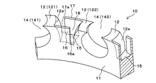
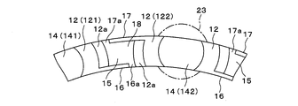
図1および図2に示すように、本発明の保持器10は、円環形状の基部11と、基部11から軸方向上方に向かって延在する一対の保持爪12の間に、玉13が嵌合されるポケット14が周方向に沿って複数形成されている合成樹脂製冠形保持器である。ポケット14の内周は、玉13の外径よりも僅かに大径な球面状をなしている。
図1および図2に示すように、本発明の保持器10は、円環形状の基部11と、基部11から軸方向上方に向かって延在する一対の保持爪12の間に、玉13が嵌合されるポケット14が周方向に沿って複数形成されている合成樹脂製冠形保持器である。ポケット14の内周は、玉13の外径よりも僅かに大径な球面状をなしている。
合成樹脂としては、ポリアミド(ナイロン66、ナイロン46等)、ポリアセタールやポリエーテルエーテルケトン(PEEK)などの熱可塑性樹脂をガラス繊維や炭素繊維で強化したものを用いることができる。そして、そのような合成樹脂を好適には大量生産に適した射出成形によって保持器10に成形される。
ポケット14を形成する一対の保持爪12のそれぞれは、ポケット14の周方向外側を臨む背面12aを有する。背面12aは、ポケット14の内周と同様に球面状をなしている。ここで、一つのポケット14と一つの保持爪12を第1ポケット141および第1保持爪121と称し、その隣に位置するポケット14を第2ポケット142および第2保持爪122と称して以下の説明に用いる。
第1ポケット141の第1保持爪121の背面12aは、第1ポケット141の隣に位置する第2ポケット142の第2保持爪122の背面と周方向に対向している。そして第1ポケット141の第1保持爪121と第2ポケット142の第2保持爪122との間には平坦部(グリース受容面)15が形成されている。この平坦部15の軸方向位置は、第1、第2ポケット141,142の中心の軸方向位置とほぼ同じである。
平坦部15の内周側には、第1ポケット141の第1保持爪121と連結された内側グリース飛散防止壁16が周方向に沿って形成されている。また、平坦部15の外周側には第2ポケット142の第2保持爪122と連結された外側グリース飛散防止壁17が周方向に沿って形成されている。これら平坦部15、内側グリース飛散防止壁16、および外側グリース飛散防止壁17によってグリース貯留部18が形成されている。内側グリース飛散防止壁16は第2保持爪122と離間して内側スリット16aを形成し、外側グリース飛散防止壁17は第1保持爪121と離間して外側スリット17aを形成している。内側および外側スリット16a,17aは、グリース貯留部18に充填されるグリースから溶出する潤滑油を玉23と軌道面へ供給する出口となる。
上記構成の保持器10において、平坦部15と内側グリース飛散防止壁16と外側グリース飛散防止壁17とで形成されるグリース貯留部18にグリースを充填する際には、平坦部15の中央を狙ってグリースをディスペンサーから吐出する。上記構成の保持器10にあっては、保持器10の内周側と外周側に、中間部にスリットがない内側グリース飛散防止壁16と外側グリース飛散防止壁17を設けているので、グリースがグリース貯留部18の外に漏れることを抑制することができる。
また、外側グリース飛散防止壁17が高速回転時の遠心力によってグリースが外輪側に飛散するのを防止することは勿論のこと、各グリース貯留部18には、内周側と外周側に1ケ所ずつだけ内側スリット16aおよび外側スリット17aが設けられているので、高速回転してもグリースがグリース貯留部18から飛散することなく、内側スリット16aおよび外側スリット17aから適切な量の潤滑油が玉23と軌道面へ供給される。したがって、本発明では、高速の揺動や高速回転してもグリースが玉23と軌道面の間や玉23とポケット14の間に入り込むことに起因するトルクの上昇やトルク変動を低減することができ、また、グリース充填時に内輪や外輪にグリースが付着することを抑制することができる。
特に、上記実施形態にあっては、グリース貯留部18の内周側と外周側で半径方向に重ならないように内側スリット16aおよび外側スリット17aを1カ所ずつ設けているので、グリースの飛散を抑制するとともに潤滑油が玉13や軌道面に適切に供給される。これによりグリース攪拌抵抗に起因する回転トルクの上昇や変動が抑制される。
また、平坦部15の軸方向位置をポケット14の中心の軸方向位置とほぼ同じにしたので、グリース貯留部18の容積が大きくなっている。したがって、より多くのグリースをグリース貯留部18に注入することができ、玉軸受の長寿命化につながる。なお、平坦部15の軸方向位置をポケット14の中心の軸方向位置よりも低くして、すなわち、平坦部15を基部11の底面に近付けて、グリース貯留部18の容積をより大きくしてグリースの充填量をさらに増やすことも可能である。
従来の冠形保持器では、そのように平坦部15の軸方向位置を低くすると保持器の保持爪の剛性が低下して変形しやすくなり、その結果、高速回転に適さなくなるという問題が生じる。しかしながら、本発明では、内周側と外周側の両方に保持爪12と連結された内側および外側グリース飛散防止壁16,17を設けたので、保持爪12の剛性低下を防ぐことができる。また、内側および外側グリース飛散防止壁16,17の一端は保持爪12と離間させて内側および外側スリット16a,17aを設けたので、グリースによる潤滑も妨げることがない。そのため、本実施形態の保持器10は、高速回転でも使用することができ、また、より多くのグリースを保持できるので玉軸受の長寿命化にも貢献する。
2.変更例
本発明は、上記実施形態に限定されるものではなく、以下のように種々の変更が可能である。
本発明は、上記実施形態に限定されるものではなく、以下のように種々の変更が可能である。
i)平坦部15に代えて軸方向にくぼむか突出するグリース受容面を形成することができる。
ii)平坦部15に凹部または凸部を一つまたは複数設けて、グリース受容面に対するグリースの付着力を向上させることができる。また、複数の凹部はディンプルを形成することができる。
iii)ポケット14の内周は円筒曲面であってもよい。
iv)保持爪12の背面12aは、軸方向に屹立する平坦面であってもよい。
v)内側スリット16aの周方向の幅と外側スリット17aの周方向の幅との関係は特定の関係に限定されない。内側スリット16aの周方向の幅と外側スリット17aの周方向の幅とが同じであってもよいし、いずれか一方が他方よりも大きくてもよい。
ii)平坦部15に凹部または凸部を一つまたは複数設けて、グリース受容面に対するグリースの付着力を向上させることができる。また、複数の凹部はディンプルを形成することができる。
iii)ポケット14の内周は円筒曲面であってもよい。
iv)保持爪12の背面12aは、軸方向に屹立する平坦面であってもよい。
v)内側スリット16aの周方向の幅と外側スリット17aの周方向の幅との関係は特定の関係に限定されない。内側スリット16aの周方向の幅と外側スリット17aの周方向の幅とが同じであってもよいし、いずれか一方が他方よりも大きくてもよい。
3.玉軸受の構成
図3は本発明の実施形態の玉軸受20を示す断面図である。この図に示す玉軸受20は、外輪21の軌道面21aと内輪22の軌道面22aとの間に、上記実施形態の保持器10によって等間隔に玉23が保持されて構成されている。
図3は本発明の実施形態の玉軸受20を示す断面図である。この図に示す玉軸受20は、外輪21の軌道面21aと内輪22の軌道面22aとの間に、上記実施形態の保持器10によって等間隔に玉23が保持されて構成されている。
保持器10の材質はナイロン66で射出成型によって成形されている。内輪22、外輪21、および玉23の材質はマルテンサイトステンレス鋼(SUS440C)とされ、熱処理によって表面硬さはHRC58以上に高められている。
玉軸受20の軸受空間には基油として40℃における基油動粘度が25mm2/s以上100mm2/s以下の合成油に、増ちょう剤としてウレア系化合物を添加したグリースがポケット14間のグリース貯留部18に充填され、軸受空間は非接触ゴムシール(図示せず)で密封されている。ウレアグリースは耐熱性に優れているので、玉軸受20の温度が上昇する高速回転や高速の揺動運動の使用に適している。ウレア化合物はジウレアまたはポリウレアが望ましい。合成油としては、エステル油、エーテル油、合成炭化水素油、シリコーン油、フッ素油等が挙げられる。これらの合成油は単独または混合して用いてもよい。合成油の替わりに、または合成油に混合して、鉱油を基油として用いることもできる。玉軸受20の内輪22の内径は、たとえば3mm以上15mm以下とすることができる。しかしながら、このサイズに限定されるわけではない。
上記構成の玉軸受20は、保持器10のグリース貯留部18に設けられた内側および外側グリース飛散防止壁16,17と、内側および外側スリット16a,17aにより、グリースが内輪22や外輪21に付着するのを抑制しつつ、内側および外側スリット16a,17aから適切に潤滑油が供給されるので、低トルクであるとともに長寿命である。このような玉軸受20はおおよそ10,000rpm以上100,000rpm以下、dmN値でいえば120万程度までの高速回転時においても遠心力によるグリースの飛散が抑制され、安定したトルクで回転することができる。同様に、高速の揺動運動時においても慣性力によるグリースの飛散が抑制され、揺動範囲内での変動が少なく、低トルクで安定して作動することができる。したがって、上記構成の玉軸受20は、家庭用電気掃除機のクリーナモータや電動工具、ファンモータ、歯科用ハンドピースなど各種高速回転機器や高速で揺動運動を行うハードディスク駆動装置のヘッドアクチュエータに組み込んで用いることに適している。
4.性能評価
発明例として本実施形態の保持器10を用いた玉軸受20の性能評価を行った結果について説明する。評価にあたっては、上述した実施形態の保持器10の構成と比較して、グリース貯留部18に内側および外側グリース飛散防止壁16,17を設けない点で異なる保持器を作製し、この保持器を搭載した玉軸受を比較例として準備した。なお、軸受の回転トルク測定の方法としては、様々な公知の方法を用いることができる。
発明例として本実施形態の保持器10を用いた玉軸受20の性能評価を行った結果について説明する。評価にあたっては、上述した実施形態の保持器10の構成と比較して、グリース貯留部18に内側および外側グリース飛散防止壁16,17を設けない点で異なる保持器を作製し、この保持器を搭載した玉軸受を比較例として準備した。なお、軸受の回転トルク測定の方法としては、様々な公知の方法を用いることができる。
(1)回転数を変化させた場合の回転トルク
図4は、発明例および比較例の玉軸受について、回転数を変化させた場合に測定された回転トルクの平均値を示す図である。図4においては、発明例の玉軸受20および比較例の玉軸受それぞれについて、回転数を5,000rpm、10,000rpm、15,000rpmと変化させたとき、各回転数において複数回測定したトルク(gf・cm)の平均値を示している。なお、測定は、発明例の玉軸受20と比較例の玉軸受とで同一の条件で行った。
図4は、発明例および比較例の玉軸受について、回転数を変化させた場合に測定された回転トルクの平均値を示す図である。図4においては、発明例の玉軸受20および比較例の玉軸受それぞれについて、回転数を5,000rpm、10,000rpm、15,000rpmと変化させたとき、各回転数において複数回測定したトルク(gf・cm)の平均値を示している。なお、測定は、発明例の玉軸受20と比較例の玉軸受とで同一の条件で行った。
図4に示すように、比較例の玉軸受では、回転数を高くした場合に回転トルクの平均値が上昇している。特に高速回転域である10,000rpmから15,000rpmに回転数を変化させた場合の回転トルクの上昇が約2倍程度と著しい。一方、発明例の玉軸受20では、回転数を高速回転域に上げた場合でも回転トルクの平均値が上昇せず、ほぼ一定であり、低トルク化を実現できている。
(2)回転トルクの変動
図5は、発明例および比較例の玉軸受について、回転数を15,000rpmとした場合の回転トルク(gf・cm)の経時変化を示す図である。
図5は、発明例および比較例の玉軸受について、回転数を15,000rpmとした場合の回転トルク(gf・cm)の経時変化を示す図である。
図5に示すように、比較例の玉軸受では、高速回転域である15,000rpmにおいて、回転トルクの測定値の変動が大きい。これに対して、発明例の玉軸受20では、比較例の玉軸受と比較してトルクの変動が小さく、安定している。
以上の評価により、発明例の玉軸受20は、比較例の玉軸受と比較して、特に高速回転域における低トルクおよび低トルク変動を実現できることが確認された。これは、発明例の玉軸受20では、高速回転してもグリースがグリース貯留部18から飛散することなく、内側スリット16aおよび外側スリット17aから適切な量の潤滑油が玉23と軌道面へ供給されるためである。また、発明例の玉軸受20では、高速での揺動や回転時にグリースが玉23と軌道面の間や玉23とポケット14の間に入り込むことに起因するトルクの上昇や変動を低減することができるためである。
(3)グリースの飛散状態
次に、玉軸受のグリースの飛散状態を評価した結果について説明する。グリースの飛散状態の評価は、所定の回転数で所定時間軸受を回転させた後、グリースの状態を目視することにより行った。表1は、5,000rpm、10,000rpm、15,000rpmの各回転数における、発明例および比較例の玉軸受のグリースの飛散状態を示している。表1において、「有」はグリースが飛散し外輪などに付着していたことを示し「無」はグリースの外輪などへの付着が無く飛散が確認できなかったことを示す。
次に、玉軸受のグリースの飛散状態を評価した結果について説明する。グリースの飛散状態の評価は、所定の回転数で所定時間軸受を回転させた後、グリースの状態を目視することにより行った。表1は、5,000rpm、10,000rpm、15,000rpmの各回転数における、発明例および比較例の玉軸受のグリースの飛散状態を示している。表1において、「有」はグリースが飛散し外輪などに付着していたことを示し「無」はグリースの外輪などへの付着が無く飛散が確認できなかったことを示す。

表1に示すように、比較的低い回転数(5000rpm)においては、発明例および比較例のいずれにおいてもグリースの飛散は観察されなかった。一方、高速回転域(10,000rpm、15,000rpm)においては、比較例の玉軸受についてグリースの飛散による外輪などへの付着が観察された。一方、発明例の玉軸受20では、高速回転域においてもグリースの飛散は観察されなかった。
このように、発明例の保持器10を備えた玉軸受20によれば、比較例の玉軸受と比較して、高速回転してもグリースが飛散し難いことが分かった。これは、上述したように、発明例の玉軸受20では、保持器10のグリース貯留部18に内側グリース飛散防止壁16および外側グリース飛散防止壁17を設けているので、グリースの飛散が抑制されているためである。
本発明の保持器および玉軸受は、家庭用電気掃除機のクリーナモータや電動工具、ファンモータ、歯科用ハンドピースなどの各種高速回転機器および高速で揺動運動を行うハードディスク駆動装置のヘッドアクチュエータに組み込んで好適に用いることができる。
10…保持器、11…基部、12…保持爪、13…玉、14…ポケット、12a…背面、15…平坦部(グリース受容面)、16…内側グリース飛散防止壁、17…外側グリース飛散防止壁、18…グリース貯留部、16a…内側スリット,17a…外側スリット、20…玉軸受、21…外輪、21a…軌道面、22…内輪、22a…軌道面、23…玉。
Claims (11)
- 円環形状の基部から軸方向に延びる一対の保持爪の間に玉が嵌合されるポケットが周方向に沿って複数形成されている合成樹脂製冠形保持器であって、
それぞれの前記保持爪は、前記ポケットの周方向外側を臨む背面を有し、
第一の前記ポケットの第一の前記保持爪の背面と、第一の前記ポケットに隣接する第二の前記ポケットの第二の前記保持爪の背面とが対向し、
第一の前記保持爪と第二の前記保持爪との間にグリース受容面が形成され、前記グリース受容面の内周側には第一の前記保持爪に連結された内側グリース飛散防止壁が周方向に沿って形成され、
前記グリース受容面の外周側には第二の前記保持爪と連結された外側グリース飛散防止壁が周方向に沿って形成され、
前記内側グリース飛散防止壁の少なくとも一部は、第二の前記保持爪と離間して内側スリットを形成し、
前記外側グリース飛散防止壁の少なくとも一部は、第一の前記保持爪と離間して外側スリットを形成している合成樹脂製冠形保持器。 - 前記内側グリース飛散防止壁および前記外側グリース飛散防止壁それぞれの周方向中間部がスリットおよび孔を有しない請求項1に記載の合成樹脂製冠形保持器。
- 前記内側スリットと前記外側スリットとが、半径方向に重ならないように設けられた請求項1または2に記載の合成樹脂製冠形保持器。
- 前記グリース受容面の軸方向位置は、第一の前記ポケットおよび前記第二の前記ポケットの中心の軸方向位置と同じかまたは低い請求項1乃至3のいずれかに記載の合成樹脂製冠形保持器。
- 前記グリース受容面が平坦部で構成された請求項1乃至4のいずれかに記載の合成樹脂製冠型保持器。
- 前記グリース受容面が軸方向にくぼむ凹部か軸方向に突出する凸部で構成された請求項1乃至4のいずれかに記載の合成樹脂製冠形保持器。
- 前記平坦部に、前記凹部または前記凸部を一または複数設けた請求項6に記載の合成樹脂製冠形保持部。
- 第一の前記ポケットおよび第二の前記ポケットの内周が円筒曲面である請求項1乃至7のいずれかに記載の合成樹脂製冠形保持器。
- 前記背面は、凸の球面状をなす請求項1乃至8のいずれかに記載の合成樹脂製冠形保持器。
- 前記背面は、軸方向に屹立する平坦面である請求項1乃至8のいずれかに記載の合成樹脂製冠形保持器。
- 内輪と外輪と、前記内輪および前記外輪の間に配置される複数の玉と、前記玉を保持する請求項1乃至10のいずれかに記載の保持器とを備えた玉軸受。
Applications Claiming Priority (2)
| Application Number | Priority Date | Filing Date | Title |
|---|---|---|---|
| JP2021041079A JP2024085426A (ja) | 2021-03-15 | 2021-03-15 | 保持器および玉軸受 |
| JP2021-041079 | 2021-03-15 |
Publications (1)
| Publication Number | Publication Date |
|---|---|
| WO2022196344A1 true WO2022196344A1 (ja) | 2022-09-22 |
Family
ID=83321488
Family Applications (1)
| Application Number | Title | Priority Date | Filing Date |
|---|---|---|---|
| PCT/JP2022/008600 Ceased WO2022196344A1 (ja) | 2021-03-15 | 2022-03-01 | 保持器および玉軸受 |
Country Status (2)
| Country | Link |
|---|---|
| JP (1) | JP2024085426A (ja) |
| WO (1) | WO2022196344A1 (ja) |
Citations (6)
| Publication number | Priority date | Publication date | Assignee | Title |
|---|---|---|---|---|
| JPH0456219U (ja) * | 1990-09-21 | 1992-05-14 | ||
| JPH04344144A (ja) * | 1991-05-21 | 1992-11-30 | Toshiba Corp | モータ |
| JP2001020957A (ja) * | 1999-07-05 | 2001-01-23 | Koyo Seiko Co Ltd | 合成樹脂製冠形保持器 |
| JP2002276669A (ja) * | 2001-03-01 | 2002-09-25 | Snr Roulements | 転がり軸受用の保持器及び同保持器の製造方法並びに軸受 |
| JP2004286060A (ja) * | 2003-03-19 | 2004-10-14 | Seiko Instruments Inc | 合成樹脂製冠型リテーナ、及び玉軸受 |
| JP2008045572A (ja) * | 2006-08-10 | 2008-02-28 | Nsk Ltd | 玉軸受用保持器及び玉軸受 |
-
2021
- 2021-03-15 JP JP2021041079A patent/JP2024085426A/ja active Pending
-
2022
- 2022-03-01 WO PCT/JP2022/008600 patent/WO2022196344A1/ja not_active Ceased
Patent Citations (6)
| Publication number | Priority date | Publication date | Assignee | Title |
|---|---|---|---|---|
| JPH0456219U (ja) * | 1990-09-21 | 1992-05-14 | ||
| JPH04344144A (ja) * | 1991-05-21 | 1992-11-30 | Toshiba Corp | モータ |
| JP2001020957A (ja) * | 1999-07-05 | 2001-01-23 | Koyo Seiko Co Ltd | 合成樹脂製冠形保持器 |
| JP2002276669A (ja) * | 2001-03-01 | 2002-09-25 | Snr Roulements | 転がり軸受用の保持器及び同保持器の製造方法並びに軸受 |
| JP2004286060A (ja) * | 2003-03-19 | 2004-10-14 | Seiko Instruments Inc | 合成樹脂製冠型リテーナ、及び玉軸受 |
| JP2008045572A (ja) * | 2006-08-10 | 2008-02-28 | Nsk Ltd | 玉軸受用保持器及び玉軸受 |
Also Published As
| Publication number | Publication date |
|---|---|
| JP2024085426A (ja) | 2024-06-27 |
Similar Documents
| Publication | Publication Date | Title |
|---|---|---|
| US5539844A (en) | Ball bearing cages and ball bearings | |
| US20100037579A1 (en) | Cotton picker spindle with grease reservoir and a grease and dirt seal | |
| JP7270409B2 (ja) | 玉軸受 | |
| JP2013204679A (ja) | 転がり軸受 | |
| JP2013064495A (ja) | スラスト軸受 | |
| WO2022196344A1 (ja) | 保持器および玉軸受 | |
| JP2023089646A (ja) | 玉軸受 | |
| EP2075479A1 (en) | Thrust bearing cage | |
| JP3250987U (ja) | 転がり軸受 | |
| CN203756734U (zh) | 自储油微量泵油润滑组合型角接触球轴承和深沟球轴承 | |
| JP2025032024A (ja) | 転がり軸受および転がり軸受用保持器 | |
| JP2007518042A (ja) | 自在継手のワッシャバッフル | |
| JP2010078136A (ja) | ボールねじ及び射出成形機 | |
| JP2005083554A (ja) | 転がり軸受 | |
| JP2709119B2 (ja) | 無潤滑転がり軸受 | |
| JP2020122493A (ja) | 玉軸受 | |
| JP7221723B2 (ja) | 玉軸受 | |
| JP6954785B2 (ja) | 玉軸受 | |
| JP2004076928A (ja) | 転がり軸受用合成樹脂製保持器及び転がり軸受 | |
| JP5781365B2 (ja) | 玉軸受用保持器および玉軸受 | |
| JP2000227152A (ja) | クラッチ内蔵形プーリユニット | |
| JP2021148250A (ja) | 転がり軸受用保持器および転がり軸受 | |
| JP3230649U (ja) | 保持器および玉軸受 | |
| JP2003278764A (ja) | 玉軸受 | |
| JP2008256166A (ja) | スラスト針状ころ軸受 |
Legal Events
| Date | Code | Title | Description |
|---|---|---|---|
| 121 | Ep: the epo has been informed by wipo that ep was designated in this application |
Ref document number: 22771098 Country of ref document: EP Kind code of ref document: A1 |
|
| NENP | Non-entry into the national phase |
Ref country code: DE |
|
| 122 | Ep: pct application non-entry in european phase |
Ref document number: 22771098 Country of ref document: EP Kind code of ref document: A1 |
|
| NENP | Non-entry into the national phase |
Ref country code: JP |