WO2022195962A1 - タイヤ - Google Patents
タイヤ Download PDFInfo
- Publication number
- WO2022195962A1 WO2022195962A1 PCT/JP2021/042852 JP2021042852W WO2022195962A1 WO 2022195962 A1 WO2022195962 A1 WO 2022195962A1 JP 2021042852 W JP2021042852 W JP 2021042852W WO 2022195962 A1 WO2022195962 A1 WO 2022195962A1
- Authority
- WO
- WIPO (PCT)
- Prior art keywords
- pattern
- tire
- pattern region
- area
- base surface
- Prior art date
- Legal status (The legal status is an assumption and is not a legal conclusion. Google has not performed a legal analysis and makes no representation as to the accuracy of the status listed.)
- Ceased
Links
Images

Classifications
-
- B—PERFORMING OPERATIONS; TRANSPORTING
- B60—VEHICLES IN GENERAL
- B60C—VEHICLE TYRES; TYRE INFLATION; TYRE CHANGING; CONNECTING VALVES TO INFLATABLE ELASTIC BODIES IN GENERAL; DEVICES OR ARRANGEMENTS RELATED TO TYRES
- B60C13/00—Tyre sidewalls; Protecting, decorating, marking, or the like, thereof
- B60C13/001—Decorating, marking or the like
Definitions
- This disclosure relates to tires.
- the smooth surface of the side surface of the tire is decorated with minute unevenness (for example, Japanese Patent Application Laid-Open No. 2019-099094).
- An object of the present disclosure is to provide a tire that can expand the range of expression of decorative parts.
- a tire according to a first aspect is provided with a decorative portion on the base surface of the tire outer surface, and the decorative portion includes a first pattern region configured to include a plurality of first projections projecting from the base surface.
- a plurality of the first pattern regions are arranged in the circumferential direction, and the areas of the plurality of first pattern regions arranged in the tire circumferential direction gradually decrease toward one or both sides in the tire circumferential direction.
- the decorative portion is arranged on the outer surface of the tire, and the decorative portion has a first pattern region configured to include a plurality of first projections projecting from the base surface in the tire circumferential direction. , and the areas of the plurality of first pattern regions arranged in the tire circumferential direction gradually decrease toward one or both sides in the tire circumferential direction. Therefore, the decorative portion of the tire according to the first aspect can expand the range of expression compared to the decorative portion that is not configured in this way.
- a second aspect is the tire according to the first aspect, wherein the first pattern region has a height of 0.05 mm or more and 1.0 mm or less from the base surface, and 0.1 mm or more and 1.0 mm or less.
- a plurality of the first protrusions arranged at intervals of .
- the pattern area can be made uneven compared to the smooth surface to have a lower brightness than the smooth surface, and the visibility of the first pattern area can be improved to make it stand out.
- a third aspect is the tire according to the first aspect or the second aspect, wherein the decorative portion includes a second pattern area having a higher brightness than the first pattern area adjacent to the first pattern area.
- the plurality of second pattern regions arranged in the tire circumferential direction gradually increase in area in the direction in which the area of the first pattern region gradually decreases.
- a plurality of second pattern regions having a higher brightness than the first pattern region are arranged adjacent to the first pattern region, and a plurality of second pattern regions are arranged in the tire circumferential direction.
- the area of the second pattern area gradually increases in the direction in which the area of the first pattern area gradually decreases. Therefore, the decorative portion of the tire according to the third aspect can expand the range of expression of the decorative portion compared to the decorative portion that is not configured in this way.
- a fourth aspect is the tire according to the third aspect, wherein the second pattern region has a height of 0.05 mm or more and 1.0 mm or less from the base surface, and a height of 0.1 mm or more and 1.0 mm or less. It is configured including a plurality of second protrusions arranged at intervals.
- the pattern area can be made uneven compared to the smooth surface to have a lower brightness than the smooth surface, and the visibility of the second pattern area can be improved to make it stand out.
- a fifth aspect is the tire according to the third aspect or the fourth aspect, wherein the decorative portion includes a third pattern region having a higher brightness than the second pattern region, adjacent to the second pattern region. are arranged multiple times.
- a plurality of third pattern regions having a higher brightness than the second pattern region are arranged adjacent to the second pattern region, so it is not configured in this way.
- the range of expression can be broadened compared to the decorative part.
- a sixth aspect is the tire according to the fifth aspect, wherein the third pattern region has a height of 0.05 mm or more and 1.0 mm or less from the base surface, and a height of 0.1 mm or more and 1.0 mm or less. It is configured to include a plurality of third projections arranged at intervals.
- the third pattern region has a plurality of third projections having a height of 0.05 mm or more and 1.0 mm or less from the base surface and arranged at intervals of 0.1 mm or more and 1.0 mm or less.
- a seventh aspect is the tire according to the fifth aspect or the sixth aspect, wherein the plurality of third pattern regions arranged in the tire circumferential direction are arranged in a direction in which the areas of the second pattern regions gradually decrease. , the area is gradually increasing.
- the areas of the plurality of third pattern regions arranged in the tire circumferential direction gradually increase in the direction in which the area of the second pattern regions gradually decreases. It is possible to expand the range of expression compared to decorations that are not configured as such.
- An eighth aspect is the tire of any one of the fifth to seventh aspects, wherein the first pattern region and the third pattern region are separated from each other.
- a ninth aspect is the tire of any one of the first to eighth aspects, wherein the first pattern region having the largest area has a mark with a higher brightness than the first pattern region. ing.
- the first pattern region having the lowest brightness and the largest area is provided with a mark having a higher brightness than the first pattern region, it is possible to expand the expression range of the decorative portion. and improve the legibility of the mark.
- the “mark” in this disclosure refers to characters, figures, symbols, three-dimensional shapes, colors, or a combination of these, among those that can be recognized by human perception.
- FIG. 4 is a plan view showing a decorative portion formed on the tire side portion of the tire according to the embodiment of the present disclosure; It is an enlarged plan view showing a part of the decorative portion.
- FIG. 11 is an enlarged plan view showing another portion of the decorative portion;
- 4 is an enlarged plan view showing part of the pattern area;
- FIG. 4 is an enlarged plan view showing part of the pattern area;
- FIG. 4 is an enlarged plan view showing part of the pattern area;
- FIG. FIG. 4 is a cross-sectional view showing an asterisk projection;
- FIG. Arrow C shown in the drawing indicates the tire circumferential direction
- arrow CW indicates the clockwise direction
- arrow CCW indicates the counterclockwise direction
- arrow R indicates the tire radial direction.
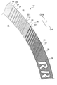
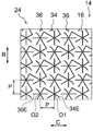
- a tire side portion 12 which is an example of the outer surface of the tire 10, is provided with a decorative portion 14 extending in the tire circumferential direction (arrow C direction).
- the decorative portion 14 has an arc shape when viewed from the axial direction of the tire 10, and is arranged at an arbitrary position in the tire circumferential direction.
- the tire side portion 12 other than the decorative portion 14 has a smooth surface like a normal tire.
- the portion of the tire side portion 12 that is formed as a smooth surface is appropriately referred to as a base surface 16 .
- the decorative portion 14 includes a first pattern area 20, a second pattern area 22, and a third pattern area 24 with different lightness (L*).
- the brightness increases in order of the first pattern region 20, the second pattern region 22, the third pattern region 24, and the base surface 16.
- FIG. In other words, the first pattern area 20 appears darkest and the base surface 16 appears brightest.
- First pattern area 20 As shown in FIGS. 1, 2, and 3, a plurality of first pattern regions 20 are provided along the tire circumferential direction (direction of arrow C) in the central portion of the decorative portion 14 in the tire circumferential direction. The area decreases in the circular direction (arrow CW direction) and the counterclockwise direction (arrow CCW direction).
- the first pattern region 20 is formed in a substantially rectangular shape in a plan view, and extends counterclockwise toward the tire circumferential direction.
- the width of the direction is decreasing.
- the first pattern region 20 is formed in a circular shape in plan view, and the area decreases in the clockwise direction. Note that as the diameter of the first pattern regions 20 increases, the adjacent regions come into contact with each other and the gap between them disappears.
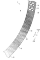
- the second pattern regions 22 are provided on the clockwise and counterclockwise sides of the decorative portion 14 .
- the second pattern region 22 is formed in a substantially rectangular shape in plan view, and the area decreases in the clockwise and counterclockwise directions.
- the two pattern regions 22 and the first pattern regions 20 are alternately arranged.
- the second pattern area 22 is formed in a circular shape in plan view, and the area decreases in the clockwise direction.
- the adjacent regions come into contact with each other and the mutual gap disappears.
- the clockwise direction side of the first pattern region 20 a portion of the second pattern region 22 and a portion of the first pattern region 20 are adjacent to each other, and the first pattern region 20 and the second pattern region 22 are adjacent to each other. In the contacting region, the ratio of the second pattern region 22 per unit area decreases in the counterclockwise direction.
- the third pattern region 24 is provided at the clockwise end and the counterclockwise end of the decorative portion 14 .
- the third pattern region 24 is formed in a substantially rectangular shape in plan view, and the area decreases toward the clockwise direction. 2 pattern areas 24 are alternately arranged.
- the third pattern region 24 is arranged adjacent to the second pattern region 22 on the second pattern region 22 side, and is the third pattern region occupied per unit area.
- the percentage of pattern area 24 decreases in the counterclockwise direction.
- the first pattern area 20 has a lower brightness than the base surface 16 and appears blacker than the base surface 16 .
- the second pattern area 22 has a higher brightness than the first pattern area 20 .
- the third pattern region 24 has a higher brightness than the second pattern region 22 . That is, the brightness decreases in the order of the base surface 16, the third pattern region 24, the second pattern region 22, and the first pattern region 20, with the base surface 16 appearing the brightest and the first pattern region 20 appearing the blackest. .
- the tire side portion A first patterned area 20, a second patterned area 22, and a third patterned area 24 may be formed on the surface of 12 .
- the first pattern region 20, the second pattern region 22, and the third pattern region 24 are formed with minute protrusions protruding from the base surface 16, whereby the first pattern region 20, the second pattern region 22, and the third pattern region 24 are formed.
- the surface of each of the three pattern regions 24 is uneven.
- first asterisk projections 34 and second asterisk projections 36 which are examples of projections, are mutually arranged. formed in a similar manner.
- the shapes of the first asterisk projection 34 and the second asterisk projection 36 are similar in their respective regions.
- the distance P between the first asterisk projection 34 and the second asterisk projection 36 adjacent to each other changes according to the similitude ratio.
- the shapes of the first asterisk projection 34 and the second asterisk projection 36 are similar in their respective regions. Accordingly, the shapes of the first asterisk projection 34 and the second asterisk projection 36 will be described below using the first pattern region 20 as an example.
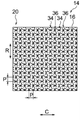
- the first pattern area 20 has a plurality of first asterisk protrusions 34 and a plurality of second asterisk protrusions 36 projecting from the base surface 16 .
- the first asterisk projections 34 and the second asterisk projections 36 are alternately arranged in the tire circumferential direction and the tire radial direction.
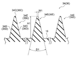
- first asterisk projection 34 As shown in FIG. 4A, the first asterisk projections 34 extend in different directions from the center O1 (see FIG. 4C) as a base point when viewed from the direction perpendicular to the base surface 16 (rotational axis direction of the tire 10). It is provided with a plurality of extending portions 34E, in this embodiment six extending portions 34E.
- the six extending portions 34E form an angle of 60° with each adjacent extending portion 34E.
- the first asterisk projection 34 has a shape in which six extending portions 34E extend radially from the center O1.
- the cross section in the direction orthogonal to the extending direction has a substantially isosceles triangle shape with a flat top surface 34C. That is, the first asterisk projection 34 has a top surface 34C and a pair of side surfaces 34D.
- the width of the top surface 34C (W1 in the drawing) is 0.02 [mm]
- the vertical angle (D in the drawing) of the first asterisk projection 34 is 26 [degrees].
- the height (H in the drawing) of the first asterisk projection 34 is a predetermined value of 0.05 mm or more and 1.0 mm or less.
- the height of the protrusion is less than 0.05 [mm]
- it becomes difficult to form the protrusion and there is a possibility that the incident light may be attenuated and the brightness may not be lowered to the extent that it appears black. be.
- the height of the projection is set to 1.0 mm or less, the difference between the rigidity of the projection portion and the rigidity of the surrounding portion of the projection is reduced, thereby suppressing local stress concentration. ing.
- the height of the protrusions in the present embodiment and the dimensions such as the spacing (pitch) of the protrusions described later can be measured using, as an example, a one-shot 3D shape measuring machine VR-3000 series manufactured by Keyence Corporation. .
- the second asterisk projection 36 is similar in shape to the first asterisk projection 34 . Specifically, the second asterisk projection 36 rotates the first asterisk projection 34 clockwise 90 degrees about the center O1 when viewed from a direction orthogonal to the base surface 16, and further, It has a shape in which the first asterisk projection 34 rotated 90 degrees around the center O1 is turned upside down. That is, the second asterisk projection 36 has six extending portions 36E extending in different directions from the center O2 (see FIG. 4C) as a base point. and sides 36D.
- the first asterisk projections 34 and the second asterisk projections 36 are alternately arranged in the tire circumferential direction and the tire radial direction, filling the entire area.
- the distance between the center O1 and the center O2 (hereinafter referred to as the "distance P") is 0.1. It is set to a predetermined value equal to or greater than [mm] and equal to or less than 1.0 [mm]. If the interval P is less than 0.1 [mm], it will be difficult to form the protrusions. Furthermore, if the interval P is larger than 1.0 [mm], there is a possibility that the incident light cannot be attenuated and the lightness cannot be lowered to the extent that it looks black.
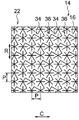
- first asterisk projections 34 and second asterisk projections 36 similar in shape to the first pattern region 20 are formed. , is lower than the density of the protrusions formed in the first pattern region 20 . As a result, the second pattern area 22 appears brighter than the first pattern area 20 .
- a first pattern region 20 having the largest area located in the center of the decorative portion 14 in the tire circumferential direction is provided with a mark as an example of a mark from the first pattern region 20.
- a logo mark 26 with a high brightness is also formed.
- the logo mark 26 of this embodiment is composed of the smooth base surface 16 .
- the incident light is reflected outward by the smooth outer surface that constitutes the base surface 16 .
- the first pattern region 20, the second pattern region 22, and the third pattern region 24 the light incident on the first asterisk projection 34 and the second asterisk projection 36 hits the side surfaces 34D and 36D shown in FIG. .
- the incident light is attenuated while being repeatedly reflected between the facing side surfaces 34D and 36D, and is reflected outward. Therefore, the first pattern area 20 , the second pattern area 22 , and the third pattern area 24 appear black compared to the base surface 16 .
- the area occupied by the base surface 16 of the second pattern area 22 per unit area is smaller than the area occupied by the base surface 16 of the first pattern area 20 per unit area.
- the area per unit area occupied by the base surface 16 of the third pattern area 24 is larger than the area per unit area occupied by the base surface 16 of the second pattern area 22 .
- the amount of light reflected outward from the second pattern area 22 is greater than the amount of light reflected outward from the first pattern area 20, and the amount of light reflected outward from the third pattern area 24 is greater.
- the amount of light reflected is greater than the amount of light reflected outward in the second pattern area 22 . That is, the brightness of the second pattern region 22 is higher than that of the first pattern region 20 , and the brightness of the third pattern region 24 is higher than that of the second pattern region 22 .
- the third pattern region 24, the second pattern region 22, and the first pattern region 20 have lower brightness in that order, and appear darkest due to the lowest brightness. Since the logo mark 26 composed of the smooth base surface 16 and having the highest brightness is arranged in the first pattern region 20 having the lowest brightness and appearing dark, the range of expression of the decorative part 14 is greatly expanded. and the visibility of the logo mark 26 can be improved.
- the first asterisk projection 34 and the second asterisk projection 36 are connected to each other, but they may be configured so that they are not connected to each other.
- the apex angle of the projections such as the first asterisk projection 34 and the second asterisk projection 36 was set to 26 [degrees], but other angles may be used. As the apex angle D increases, the proportion of the reflected light reflected by the side surfaces 34D and 36D returning to the incident direction increases, resulting in a relatively high brightness.
- the first asterisk projection 34 and the second asterisk projection 36 provided with a plurality of radially extending extensions 34E are given as examples of projections, but the present disclosure is not limited to this, and the projections
- the planar view shape is not limited to radial or linear, and may be a so-called embossed pattern.
- Grain patterns are patterns including, for example, leather patterns, satin patterns, wood grain patterns, texture patterns, and geometric patterns.
- the protrusion may be tapered, such as rib-shaped or conical-shaped.
- first pattern region 20, the second pattern region 22, and the third pattern region 24 are not limited to the shapes shown in the above embodiments, and may have different shapes, and the shape of each region is arbitrary.
- the decorative portion 14 of the above embodiment has three pattern areas with different brightnesses, it may have four or more pattern areas with different brightnesses.
- the logo mark 26 is composed of the smooth base surface 16, but if the brightness is higher than that of the first pattern area 20, the logo mark 26 need not be composed of the smooth base surface 16. Further, in the above-described embodiment, the logo mark 26 is given as an example of the mark, but the mark provided in the first pattern area 20 may be something other than the logo mark 26 .
Landscapes
- Engineering & Computer Science (AREA)
- Mechanical Engineering (AREA)
- Tires In General (AREA)
Priority Applications (3)
| Application Number | Priority Date | Filing Date | Title |
|---|---|---|---|
| EP21931705.4A EP4309920A4 (en) | 2021-03-16 | 2021-11-22 | Tire |
| US18/548,228 US20240227462A9 (en) | 2021-03-16 | 2021-11-22 | Tire |
| CN202180095719.6A CN116981576B (zh) | 2021-03-16 | 2021-11-22 | 轮胎 |
Applications Claiming Priority (2)
| Application Number | Priority Date | Filing Date | Title |
|---|---|---|---|
| JP2021042928A JP7592523B2 (ja) | 2021-03-16 | 2021-03-16 | タイヤ |
| JP2021-042928 | 2021-03-16 |
Publications (1)
| Publication Number | Publication Date |
|---|---|
| WO2022195962A1 true WO2022195962A1 (ja) | 2022-09-22 |
Family
ID=83320062
Family Applications (1)
| Application Number | Title | Priority Date | Filing Date |
|---|---|---|---|
| PCT/JP2021/042852 Ceased WO2022195962A1 (ja) | 2021-03-16 | 2021-11-22 | タイヤ |
Country Status (5)
| Country | Link |
|---|---|
| US (1) | US20240227462A9 (enExample) |
| EP (1) | EP4309920A4 (enExample) |
| JP (2) | JP7592523B2 (enExample) |
| CN (1) | CN116981576B (enExample) |
| WO (1) | WO2022195962A1 (enExample) |
Citations (9)
| Publication number | Priority date | Publication date | Assignee | Title |
|---|---|---|---|---|
| JP2012006531A (ja) * | 2010-06-28 | 2012-01-12 | Yokohama Rubber Co Ltd:The | 空気入りタイヤ |
| WO2013125165A1 (ja) * | 2012-02-24 | 2013-08-29 | 株式会社ブリヂストン | 空気入りタイヤ |
| JP2015042537A (ja) * | 2013-08-26 | 2015-03-05 | 横浜ゴム株式会社 | 空気入りタイヤ |
| JP2016175457A (ja) * | 2015-03-19 | 2016-10-06 | 株式会社ブリヂストン | タイヤ |
| JP2019099094A (ja) | 2017-12-07 | 2019-06-24 | 株式会社ブリヂストン | タイヤ |
| JP2019104279A (ja) * | 2017-12-08 | 2019-06-27 | 株式会社ブリヂストン | タイヤ |
| JP2021042928A (ja) | 2019-09-13 | 2021-03-18 | 株式会社九州日昌 | 加熱装置および加熱方法 |
| JP2021091330A (ja) * | 2019-12-11 | 2021-06-17 | 住友ゴム工業株式会社 | 空気入りタイヤ |
| JP2021104745A (ja) * | 2019-12-26 | 2021-07-26 | 住友ゴム工業株式会社 | 空気入りタイヤ |
Family Cites Families (9)
| Publication number | Priority date | Publication date | Assignee | Title |
|---|---|---|---|---|
| EP0738617A3 (en) * | 1995-04-19 | 1997-05-07 | Bridgestone Corp | Pneumatic tires with ornamentation including several streaks |
| JPH10193923A (ja) * | 1997-01-08 | 1998-07-28 | Bridgestone Corp | 少なくとも2つの円弧状標章を備えたタイヤ |
| US20020174928A1 (en) * | 2001-05-25 | 2002-11-28 | Ratliff Billy Joe | Tire sidewall |
| JP5358404B2 (ja) * | 2009-11-19 | 2013-12-04 | 株式会社ブリヂストン | 空気入りタイヤ |
| JP6232844B2 (ja) * | 2013-08-26 | 2017-11-22 | 横浜ゴム株式会社 | 空気入りタイヤ |
| JP5869019B2 (ja) * | 2014-03-05 | 2016-02-24 | 株式会社ブリヂストン | タイヤ |
| JP6960320B2 (ja) * | 2017-12-08 | 2021-11-05 | 株式会社ブリヂストン | タイヤ |
| JP6948930B2 (ja) * | 2017-12-13 | 2021-10-13 | 株式会社ブリヂストン | タイヤ |
| JP7138039B2 (ja) * | 2018-12-25 | 2022-09-15 | 株式会社ブリヂストン | タイヤ |
-
2021
- 2021-03-16 JP JP2021042928A patent/JP7592523B2/ja active Active
- 2021-11-22 WO PCT/JP2021/042852 patent/WO2022195962A1/ja not_active Ceased
- 2021-11-22 US US18/548,228 patent/US20240227462A9/en not_active Abandoned
- 2021-11-22 CN CN202180095719.6A patent/CN116981576B/zh active Active
- 2021-11-22 EP EP21931705.4A patent/EP4309920A4/en active Pending
-
2024
- 2024-08-09 JP JP2024134099A patent/JP7734806B2/ja active Active
Patent Citations (9)
| Publication number | Priority date | Publication date | Assignee | Title |
|---|---|---|---|---|
| JP2012006531A (ja) * | 2010-06-28 | 2012-01-12 | Yokohama Rubber Co Ltd:The | 空気入りタイヤ |
| WO2013125165A1 (ja) * | 2012-02-24 | 2013-08-29 | 株式会社ブリヂストン | 空気入りタイヤ |
| JP2015042537A (ja) * | 2013-08-26 | 2015-03-05 | 横浜ゴム株式会社 | 空気入りタイヤ |
| JP2016175457A (ja) * | 2015-03-19 | 2016-10-06 | 株式会社ブリヂストン | タイヤ |
| JP2019099094A (ja) | 2017-12-07 | 2019-06-24 | 株式会社ブリヂストン | タイヤ |
| JP2019104279A (ja) * | 2017-12-08 | 2019-06-27 | 株式会社ブリヂストン | タイヤ |
| JP2021042928A (ja) | 2019-09-13 | 2021-03-18 | 株式会社九州日昌 | 加熱装置および加熱方法 |
| JP2021091330A (ja) * | 2019-12-11 | 2021-06-17 | 住友ゴム工業株式会社 | 空気入りタイヤ |
| JP2021104745A (ja) * | 2019-12-26 | 2021-07-26 | 住友ゴム工業株式会社 | 空気入りタイヤ |
Non-Patent Citations (1)
| Title |
|---|
| See also references of EP4309920A4 |
Also Published As
| Publication number | Publication date |
|---|---|
| EP4309920A1 (en) | 2024-01-24 |
| JP2024153933A (ja) | 2024-10-29 |
| CN116981576B (zh) | 2025-10-03 |
| CN116981576A (zh) | 2023-10-31 |
| JP2022142664A (ja) | 2022-09-30 |
| US20240131874A1 (en) | 2024-04-25 |
| EP4309920A4 (en) | 2024-08-28 |
| US20240227462A9 (en) | 2024-07-11 |
| JP7734806B2 (ja) | 2025-09-05 |
| JP7592523B2 (ja) | 2024-12-02 |
Similar Documents
| Publication | Publication Date | Title |
|---|---|---|
| WO2019116993A1 (ja) | タイヤ | |
| JP7087246B2 (ja) | タイヤ | |
| JP2017001437A (ja) | タイヤ | |
| JP6495736B2 (ja) | タイヤ | |
| WO2019116992A1 (ja) | タイヤ | |
| US20200369095A1 (en) | Tire | |
| JP6436861B2 (ja) | タイヤ | |
| WO2013105629A1 (ja) | 空気入りタイヤ | |
| WO2019111857A1 (ja) | タイヤ | |
| WO2022195962A1 (ja) | タイヤ | |
| JP7760006B2 (ja) | タイヤ | |
| JP6441170B2 (ja) | タイヤ | |
| JP7087248B2 (ja) | タイヤ | |
| JP6549414B2 (ja) | タイヤ | |
| JP6303510B2 (ja) | 陶磁器 | |
| WO2022195961A1 (ja) | タイヤ | |
| JP2016215701A (ja) | タイヤ | |
| JP2024153933A5 (enExample) |
Legal Events
| Date | Code | Title | Description |
|---|---|---|---|
| 121 | Ep: the epo has been informed by wipo that ep was designated in this application |
Ref document number: 21931705 Country of ref document: EP Kind code of ref document: A1 |
|
| WWE | Wipo information: entry into national phase |
Ref document number: 18548228 Country of ref document: US |
|
| WWE | Wipo information: entry into national phase |
Ref document number: 202180095719.6 Country of ref document: CN |
|
| WWE | Wipo information: entry into national phase |
Ref document number: 2021931705 Country of ref document: EP |
|
| NENP | Non-entry into the national phase |
Ref country code: DE |
|
| ENP | Entry into the national phase |
Ref document number: 2021931705 Country of ref document: EP Effective date: 20231016 |
|
| WWG | Wipo information: grant in national office |
Ref document number: 202180095719.6 Country of ref document: CN |