WO2022190766A1 - 冷却装置 - Google Patents
冷却装置 Download PDFInfo
- Publication number
- WO2022190766A1 WO2022190766A1 PCT/JP2022/005522 JP2022005522W WO2022190766A1 WO 2022190766 A1 WO2022190766 A1 WO 2022190766A1 JP 2022005522 W JP2022005522 W JP 2022005522W WO 2022190766 A1 WO2022190766 A1 WO 2022190766A1
- Authority
- WO
- WIPO (PCT)
- Prior art keywords
- cooling
- cooling tank
- refrigerant liquid
- liquid
- tank
- Prior art date
Links
- 238000001816 cooling Methods 0.000 title claims abstract description 207
- 239000007788 liquid Substances 0.000 claims abstract description 253
- 239000003507 refrigerant Substances 0.000 claims abstract description 195
- 230000005484 gravity Effects 0.000 claims abstract description 16
- 238000010438 heat treatment Methods 0.000 claims description 16
- 230000001737 promoting effect Effects 0.000 claims 1
- 239000012071 phase Substances 0.000 description 19
- 238000009835 boiling Methods 0.000 description 17
- 230000007423 decrease Effects 0.000 description 17
- 239000012808 vapor phase Substances 0.000 description 13
- 239000002826 coolant Substances 0.000 description 6
- 238000001704 evaporation Methods 0.000 description 6
- 239000000463 material Substances 0.000 description 4
- 238000011144 upstream manufacturing Methods 0.000 description 4
- 230000008016 vaporization Effects 0.000 description 4
- YCKRFDGAMUMZLT-UHFFFAOYSA-N Fluorine atom Chemical compound [F] YCKRFDGAMUMZLT-UHFFFAOYSA-N 0.000 description 3
- 238000009833 condensation Methods 0.000 description 3
- 230000005494 condensation Effects 0.000 description 3
- 230000008020 evaporation Effects 0.000 description 3
- 229910052731 fluorine Inorganic materials 0.000 description 3
- 239000011737 fluorine Substances 0.000 description 3
- 239000011347 resin Substances 0.000 description 3
- 229920005989 resin Polymers 0.000 description 3
- 230000000630 rising effect Effects 0.000 description 3
- 238000009834 vaporization Methods 0.000 description 3
- 238000004090 dissolution Methods 0.000 description 2
- 230000020169 heat generation Effects 0.000 description 2
- 238000009413 insulation Methods 0.000 description 2
- 238000012986 modification Methods 0.000 description 2
- 230000004048 modification Effects 0.000 description 2
- 238000007789 sealing Methods 0.000 description 2
- 239000003566 sealing material Substances 0.000 description 2
- TXEYQDLBPFQVAA-UHFFFAOYSA-N tetrafluoromethane Chemical compound FC(F)(F)F TXEYQDLBPFQVAA-UHFFFAOYSA-N 0.000 description 2
- RYGMFSIKBFXOCR-UHFFFAOYSA-N Copper Chemical compound [Cu] RYGMFSIKBFXOCR-UHFFFAOYSA-N 0.000 description 1
- 229910052782 aluminium Inorganic materials 0.000 description 1
- XAGFODPZIPBFFR-UHFFFAOYSA-N aluminium Chemical compound [Al] XAGFODPZIPBFFR-UHFFFAOYSA-N 0.000 description 1
- 230000005540 biological transmission Effects 0.000 description 1
- 239000003795 chemical substances by application Substances 0.000 description 1
- 229910052802 copper Inorganic materials 0.000 description 1
- 239000010949 copper Substances 0.000 description 1
- 239000003112 inhibitor Substances 0.000 description 1
- 239000007791 liquid phase Substances 0.000 description 1
- 238000004519 manufacturing process Methods 0.000 description 1
- 229910052751 metal Inorganic materials 0.000 description 1
- 239000002184 metal Substances 0.000 description 1
- 239000007769 metal material Substances 0.000 description 1
- 239000002245 particle Substances 0.000 description 1
- RVZRBWKZFJCCIB-UHFFFAOYSA-N perfluorotributylamine Chemical compound FC(F)(F)C(F)(F)C(F)(F)C(F)(F)N(C(F)(F)C(F)(F)C(F)(F)C(F)(F)F)C(F)(F)C(F)(F)C(F)(F)C(F)(F)F RVZRBWKZFJCCIB-UHFFFAOYSA-N 0.000 description 1
- 238000005057 refrigeration Methods 0.000 description 1
Images


Classifications
-
- H—ELECTRICITY
- H05—ELECTRIC TECHNIQUES NOT OTHERWISE PROVIDED FOR
- H05K—PRINTED CIRCUITS; CASINGS OR CONSTRUCTIONAL DETAILS OF ELECTRIC APPARATUS; MANUFACTURE OF ASSEMBLAGES OF ELECTRICAL COMPONENTS
- H05K7/00—Constructional details common to different types of electric apparatus
- H05K7/20—Modifications to facilitate cooling, ventilating, or heating
- H05K7/2029—Modifications to facilitate cooling, ventilating, or heating using a liquid coolant with phase change in electronic enclosures
- H05K7/203—Modifications to facilitate cooling, ventilating, or heating using a liquid coolant with phase change in electronic enclosures by immersion
-
- F—MECHANICAL ENGINEERING; LIGHTING; HEATING; WEAPONS; BLASTING
- F25—REFRIGERATION OR COOLING; COMBINED HEATING AND REFRIGERATION SYSTEMS; HEAT PUMP SYSTEMS; MANUFACTURE OR STORAGE OF ICE; LIQUEFACTION SOLIDIFICATION OF GASES
- F25D—REFRIGERATORS; COLD ROOMS; ICE-BOXES; COOLING OR FREEZING APPARATUS NOT OTHERWISE PROVIDED FOR
- F25D9/00—Devices not associated with refrigerating machinery and not covered by groups F25D1/00 - F25D7/00; Combinations of devices covered by two or more of the groups F25D1/00 - F25D7/00
-
- F—MECHANICAL ENGINEERING; LIGHTING; HEATING; WEAPONS; BLASTING
- F28—HEAT EXCHANGE IN GENERAL
- F28D—HEAT-EXCHANGE APPARATUS, NOT PROVIDED FOR IN ANOTHER SUBCLASS, IN WHICH THE HEAT-EXCHANGE MEDIA DO NOT COME INTO DIRECT CONTACT
- F28D15/00—Heat-exchange apparatus with the intermediate heat-transfer medium in closed tubes passing into or through the conduit walls ; Heat-exchange apparatus employing intermediate heat-transfer medium or bodies
- F28D15/02—Heat-exchange apparatus with the intermediate heat-transfer medium in closed tubes passing into or through the conduit walls ; Heat-exchange apparatus employing intermediate heat-transfer medium or bodies in which the medium condenses and evaporates, e.g. heat pipes
-
- H—ELECTRICITY
- H01—ELECTRIC ELEMENTS
- H01L—SEMICONDUCTOR DEVICES NOT COVERED BY CLASS H10
- H01L23/00—Details of semiconductor or other solid state devices
- H01L23/34—Arrangements for cooling, heating, ventilating or temperature compensation ; Temperature sensing arrangements
- H01L23/42—Fillings or auxiliary members in containers or encapsulations selected or arranged to facilitate heating or cooling
- H01L23/427—Cooling by change of state, e.g. use of heat pipes
-
- H—ELECTRICITY
- H05—ELECTRIC TECHNIQUES NOT OTHERWISE PROVIDED FOR
- H05K—PRINTED CIRCUITS; CASINGS OR CONSTRUCTIONAL DETAILS OF ELECTRIC APPARATUS; MANUFACTURE OF ASSEMBLAGES OF ELECTRICAL COMPONENTS
- H05K7/00—Constructional details common to different types of electric apparatus
- H05K7/20—Modifications to facilitate cooling, ventilating, or heating
- H05K7/2029—Modifications to facilitate cooling, ventilating, or heating using a liquid coolant with phase change in electronic enclosures
- H05K7/20327—Accessories for moving fluid, for connecting fluid conduits, for distributing fluid or for preventing leakage, e.g. pumps, tanks or manifolds
-
- H—ELECTRICITY
- H05—ELECTRIC TECHNIQUES NOT OTHERWISE PROVIDED FOR
- H05K—PRINTED CIRCUITS; CASINGS OR CONSTRUCTIONAL DETAILS OF ELECTRIC APPARATUS; MANUFACTURE OF ASSEMBLAGES OF ELECTRICAL COMPONENTS
- H05K7/00—Constructional details common to different types of electric apparatus
- H05K7/20—Modifications to facilitate cooling, ventilating, or heating
- H05K7/2089—Modifications to facilitate cooling, ventilating, or heating for power electronics, e.g. for inverters for controlling motor
- H05K7/20936—Liquid coolant with phase change
Definitions
- the present disclosure relates to a cooling device that cools a heating element such as an electronic device by immersing it in a refrigerant liquid.
- the refrigerant liquid may decrease due to the vaporization of the refrigerant liquid due to the heat generated by the heating element, resulting in insufficient cooling of the heating element.
- Patent Document 1 a sealed tank containing a sealing material is provided outside a cooling tank in which a heating element is immersed in a refrigerant liquid, and the sealed tank functions as a trap or a seal.
- a device for suppressing the discharge of the generated refrigerant vapor to the outside has been proposed.
- the temperature of the cooling tank becomes higher than that of the sealed tank due to the heat generated by the heating element.
- the refrigerant liquid or the sealing material may overflow from the sealing tank.
- an object of the present disclosure is to suppress decrease in the coolant liquid in the cooling tank in a cooling device including a cooling tank in which a heating element is cooled by being immersed in the coolant liquid.
- the cooling device of the present disclosure includes a cooling tank, a liquid storage tank, and a connector.
- the cooling bath stores a refrigerant liquid for immersing and cooling the heating element.
- the reservoir stores refrigerant liquid outside the cooling tank and has an atmospheric opening open to the atmosphere.
- the connecting portion connects the liquid storage tank and the cooling tank, and allows the refrigerant liquid to pass therethrough.
- the cooling tank side opening formed on the cooling tank side of the connecting portion is positioned below or at the same height as the liquid surface of the refrigerant liquid in the cooling tank in the direction of gravity.
- the gas generated in the cooling bath is stored in the upper part of the cooling bath to form a gas portion.
- Refrigerant liquid flows between the cooling tank and the liquid storage tank via the connecting part according to the volume change of the gas portion.
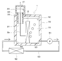
- the cooling device 1 of the first embodiment includes a cooling tank 10, a liquid storage tank 20 and a connecting portion 30.
- the cooling tank 10, the liquid storage tank 20, and the connecting part 30 can be made of, for example, a resin material or a metal material.
- the cooling bath 10 is a container-shaped member that accommodates the electronic device 2 to be cooled.
- the electronic device 2 is a heating element that generates heat as it operates and requires cooling.
- an electronic board on which a heating element is mounted, an inverter, or the like can be used.
- the electronic device 2 of this embodiment is a plate-like member, and is arranged so that the plate surface is parallel to the direction of gravity.
- the electronic device 2 corresponds to the heating element of the present disclosure.
- a coolant liquid 11 for cooling the electronic device 2 is stored in the cooling bath 10 .
- the electronic device 2 is in a state of being immersed in the refrigerant liquid 11 .
- a fluorine-based inert liquid is used as the refrigerant liquid 11 .
- a fluorine-based inert liquid is a refrigerant liquid that is excellent in insulating properties, heat transfer properties, and stability.
- a low boiling point refrigerant liquid 11 having a boiling point lower than about 120° C. is used.
- fluorine-based inert liquid As the fluorine-based inert liquid, Novec (trade name of 3M Company) having a hydrofluoroether (HFE) structure and Fluorinert (trade name of 3M Company) having a perfluorocarbon (PFC) structure can be used.
- HFE hydrofluoroether
- PFC perfluorocarbon
- the boiling point of the refrigerant liquid 11 is lower than the heat generation temperature of the electronic device 2 .
- the refrigerant liquid 11 having a boiling point lower than the heat generation temperature of the electronic device 2 by about 10 to 20° C. is used. Therefore, the refrigerant liquid 11 can be boiled by the heat generated by the electronic device 2 , and boiling cooling is performed in which the refrigerant liquid 11 boils in the cooling tank 10 and absorbs heat from the electronic device 2 .
- subcooled boiling is performed in which the refrigerant liquid 11 in contact with the electronic device 2 boils, and the refrigerant liquid 11 in the cooling tank 10 boils in a subcooled liquid having a temperature lower than the boiling point.
- the vapor-phase refrigerant generated by boiling the refrigerant liquid 11 condenses and shrinks in the subcooled liquid, but bubbles that cannot be condensed move upward inside the refrigerant liquid 11 .
- the gas generated inside the cooling tank 10 is stored in the upper part of the cooling tank 10 to form the gas portion 12 .
- the gas portion 12 includes gas-phase refrigerant, dissolved gas released from the refrigerant liquid 11, air present in the cooling tank 10 from the beginning, and the like.
- the volume of the gas portion 12 is variable and may become zero.
- the gas-phase refrigerant contained in the gas portion 12 is generated by evaporating the refrigerant liquid 11 inside the cooling tank 10 . Vaporization of the refrigerant liquid 11 includes boiling and evaporation of the refrigerant liquid 11 .
- the gas-phase refrigerant contained in the gas portion 12 becomes the liquid-phase refrigerant liquid 11 by condensing.
- Dissolved gas mainly composed of the atmosphere is dissolved in the refrigerant liquid 11 .
- the dissolved gas contained in the gas portion 12 is generated when the dissolved gas dissolved in the refrigerant liquid 11 is released from the refrigerant liquid 11 .
- the solubility of the gas dissolved in the refrigerant liquid 11 varies depending on the temperature of the refrigerant liquid 11 and the like. As the temperature of the refrigerant liquid 11 rises, the solubility of the dissolved gas decreases and the dissolved gas is released from the refrigerant liquid 11 .
- the dissolved gas released from the refrigerant liquid 11 forms the gas portion 12 together with the gas-phase refrigerant.
- the dissolved gas contained in the gas portion 12 can be dissolved again in the refrigerant liquid 11 due to the temperature drop of the refrigerant liquid 11 .
- the liquid storage tank 20 is a container-like member capable of storing the refrigerant liquid 11 inside.
- the liquid storage tank 20 is provided outside the cooling tank 10 .
- the liquid storage tank 20 is provided facing the upper surface of the cooling tank 10 .
- An air opening 21 is provided at the top of the liquid storage tank 20 .
- the inside of the liquid storage tank 20 communicates with the atmosphere via an air opening 21 from above.
- the liquid storage tank 20 is open to the atmosphere, and the atmosphere exists above the refrigerant liquid 11 inside the liquid storage tank 20 .
- the liquid storage tank 20 is connected to the cooling tank 10 by a connecting portion 30 .
- the connecting portion 30 is a tubular member, through which the refrigerant liquid 11 can pass.
- the connecting portion 30 has one end connected to the cooling tank 10 and the other end connected to the liquid storage tank 20 .
- the connection part 30 of this embodiment is provided so as to penetrate the upper surface of the cooling bath 10 .
- the inside of the liquid storage tank 20 communicates with the cooling tank 10 through the connecting part 30 below. Since the inside of the liquid storage tank 20 is open to the atmosphere through the atmospheric opening 21, the inside of the liquid storage tank 20 and the inside of the cooling tank 10 are maintained at atmospheric pressure. In other words, the cooling device 1 of this embodiment is open to the atmosphere.
- a cooling tank side opening 31 is formed in the connecting part 30 on the cooling tank 10 side.
- the cooling tank side opening 31 is provided at the lower end portion of the connecting portion 30 in the gravitational direction, and the cooling tank side opening 31 opens downward in the gravitational direction.
- the liquid surface of the refrigerant liquid 11 in the cooling tank 10 is normally located above the cooling tank side opening 31, and can descend to the cooling tank side opening 31 when the volume of the gas portion 12 increases. Therefore, the cooling tank side opening 31 is located below or at the same height as the liquid surface of the refrigerant liquid 11 in the cooling tank 10 in the direction of gravity. That is, the gravity direction height H2 of the cooling tank side opening 31 is at a position lower than or at the same position as the liquid level height H1 of the refrigerant liquid 11 .
- the inside of the liquid storage tank 20 communicates with the inside of the cooling tank 10 via the connecting part 30 . Therefore, the refrigerant liquid 11 can flow between the cooling tank 10 and the liquid storage tank 20 via the connecting portion 30 .
- the refrigerant liquid 11 flows between the cooling tank 10 and the liquid storage tank 20 according to the volume change of the gas portion 12 .
- the volume of the refrigerant liquid 11 in the cooling tank 10 and the volume of the refrigerant liquid 11 in the liquid storage tank 20 interlock and fluctuate. Specifically, when the volume of the refrigerant liquid 11 in the cooling tank 10 decreases, the volume of the refrigerant liquid 11 in the liquid storage tank 20 increases. The volume of refrigerant liquid 11 decreases.
- the cooling tank 10 and the liquid storage tank 20 are not in contact with each other, and a gap is formed between the cooling tank 10 and the liquid storage tank 20 .
- An air layer formed by a gap formed between the cooling tank 10 and the liquid storage tank 20 constitutes a heat insulating portion 40 .
- the heat insulation part 40 suppresses heat transfer between the cooling tank 10 and the liquid storage tank 20 .
- a circulation circuit 50 for circulating the refrigerant liquid 11 in the cooling tank 10 is connected to the cooling tank 10 .
- a circulation pump 51 and a heat exchanger 52 are provided in the circulation circuit 50 .
- the circulation pump 51 pressurizes the refrigerant liquid 11 and circulates it in the circulation circuit 50 .
- the heat exchanger 52 radiates heat from the refrigerant liquid 11 to cool it.
- a radiator that cools the refrigerant liquid 11 by exchanging heat with the outside air, or a chiller that cools the refrigerant liquid 11 by exchanging heat with the low-temperature refrigerant of the refrigeration cycle, or the like can be used.
- the circulation circuit 50 is connected to the cooling tank 10 at a circulation circuit inlet portion 53 and a circulation circuit outlet portion 54 .
- the refrigerant liquid 11 in the cooling bath 10 flows into the circulation circuit 50 through the circulation circuit inlet portion 53 .
- the refrigerant liquid 11 that has circulated through the circulation circuit 50 flows out to the cooling bath 10 through the circulation circuit outlet portion 54 .
- a flow of the refrigerant liquid 11 is formed from the circulation circuit outlet portion 54 toward the circulation circuit inlet portion 53 .
- the circulation circuit outlet portion 54 is provided on the left side of the cooling bath 10 and the circulation circuit inlet portion 53 is provided on the right side of the cooling bath 10 . Therefore, a flow of the refrigerant liquid 11 from left to right is formed inside the cooling tank 10 .
- the cooling tank side opening 31 of the connecting portion 30 described above is provided at a position where it is difficult for the gas-phase refrigerant to flow.
- the cooling tank side opening 31 is provided on the upstream side of the cooling tank 10 in the flow direction of the refrigerant liquid 11 . That is, the cooling tank side opening 31 is provided closer to the circulation circuit outlet 54 than the circulation circuit inlet 53 in the flow direction of the refrigerant liquid 11 .
- the heat generated by the electronic device 2 boils the refrigerant liquid 11 in the vicinity of the electronic device 2, generating a vapor phase refrigerant.
- the gas-phase refrigerant turns into bubbles and rises inside the cooling tank 10 to form the gas portion 12 .
- the dissolved gas released from the refrigerant liquid 11 due to the temperature rise of the refrigerant liquid 11 also forms the gas portion 12 together with the gas-phase refrigerant.
- the vapor-phase refrigerant obtained by vaporizing the refrigerant liquid 11 and the dissolved gas released from the refrigerant liquid 11 are stored inside the cooling tank 10 .
- the vapor-phase refrigerant generated by boiling rises in the refrigerant liquid 11 as bubbles. Since the refrigerant liquid 11 in the cooling tank 10 is a sub-cooled liquid, the air bubbles made of the vapor-phase refrigerant are cooled by the refrigerant liquid 11 when rising inside the refrigerant liquid 11, and the vapor-phase refrigerant is condensed. As a result, the bubbles made of the gas-phase refrigerant shrink while rising inside the refrigerant liquid 11, and when the degree of subcooling of the refrigerant liquid 11 is large, the bubbles disappear.
- the refrigerant liquid 11 in the cooling tank 10 is supplied to the heat exchanger 52 via the circulation circuit 50 and cooled in the heat exchanger 52 . Cooling by the heat exchanger 52 can positively maintain the subcooled state of the refrigerant liquid 11 .
- the volume of the gas portion 12 increases due to vaporization of the refrigerant liquid 11 and release of dissolved gas from the refrigerant liquid 11 .
- the volume of the refrigerant liquid 11 inside the cooling tank 10 decreases.
- the refrigerant liquid 11 flows from the cooling tank 10 to the liquid storage tank 20 and the volume of the refrigerant liquid 11 inside the liquid storage tank 20 increases.
- the temperature of the refrigerant liquid 11 is lowered by reducing the amount of heat generated by the electronic equipment 2, increasing the cooling capacity of the heat exchanger 52, and the like.
- the decrease in the temperature of the refrigerant liquid 11 promotes condensation of the gas-phase refrigerant contained in the gas portion 12 and promotes dissolution of the dissolved gas contained in the gas portion 12 into the refrigerant liquid 11 .
- the volume of the gas portion 12 decreases due to the condensation of the gas-phase refrigerant contained in the gas portion 12 and the dissolution of the dissolved gas contained in the gas portion 12 into the refrigerant liquid 11, and the volume of the refrigerant liquid 11 decreases. increases. As the volume of the refrigerant liquid 11 increases, the refrigerant liquid 11 flows from the liquid storage tank 20 to the cooling tank 10 , and the volume of the refrigerant liquid 11 inside the liquid storage tank 20 decreases.
- the cooling tank side opening 31 of the connecting part 30 is positioned below or at the same height as the liquid surface of the refrigerant liquid 11 in the cooling tank 10 in the gravitational direction. Furthermore, the gas generated in the cooling tank 10 is stored in the upper part of the cooling tank 10 to form the gas part 12, and according to the volume change of the gas part 12, the cooling tank 10 and the storage liquid via the connection part 30 Refrigerant liquid 11 flows between tank 20 . As a result, it is possible to prevent the gas-phase refrigerant from flowing out from the atmosphere opening 21 of the liquid storage tank 20 via the connecting portion 30 . As a result, even if the cooling device 1 is used for a long period of time, the reduction of the refrigerant liquid 11 in the cooling tank 10 can be suppressed.
- the air-open type cooling device 1 having the air opening 21 communicating with the atmosphere is used.
- the reduction of the refrigerant liquid 11 in the cooling tank 10 can be suppressed without using a pressure-resistant container for enclosing the refrigerant liquid 11 . Therefore, the cooling device 1 can be downsized.
- boiling cooling is performed in which the heat generated by the electronic device 2 causes the refrigerant liquid 11 to boil.
- the electronic device 2 can be efficiently cooled, but on the other hand, a large amount of gaseous refrigerant is generated, and the gaseous refrigerant tends to flow out to the outside. According to the present embodiment, even in the cooling device 1 that performs boiling cooling in which the refrigerant liquid 11 boils, the decrease in the refrigerant liquid 11 can be effectively suppressed.
- the refrigerant liquid 11 in the cooling tank 10 is a subcooled liquid, and subcooled boiling is performed. Therefore, the vapor-phase refrigerant generated by the boiling of the refrigerant liquid 11 due to the heat generated by the electronic device 2 is cooled and condensed by the refrigerant liquid 11 made of the subcooled liquid. As a result, the gas-phase refrigerant can be suppressed from flowing through the circulation circuit 50 to the circulation pump 51 and the heat exchanger 52, and the performance of the circulation pump 51 and the heat exchanger 52 can be maintained, so that they can be used stably. can.
- the refrigerant liquid 11 in the cooling tank 10 is circulated by the circulation circuit 50 and the refrigerant liquid 11 is cooled by the heat exchanger 52 .
- the temperature rise of the refrigerant liquid 11 can be suppressed, and the vapor-phase refrigerant can be effectively cooled by the refrigerant liquid 11 in a subcooled state.
- an increase in the volume of the gas portion 12 can be suppressed, and a decrease in the liquid level of the refrigerant liquid 11 in the cooling tank 10 and an increase in the liquid level of the refrigerant liquid 11 in the liquid storage tank 20 can be suppressed.
- the cooling tank side opening 31 of the connecting portion 30 is provided on the upstream side of the cooling tank 10 in the coolant flow direction. Since the bubbles made of the gas-phase refrigerant rise while moving downstream in the flow direction of the refrigerant liquid 11 , they rise while moving away from the cooling tank side opening 31 . Therefore, it is possible to suppress the gas-phase refrigerant from flowing into the cooling tank side opening 31 provided on the upstream side of the cooling tank 10 in the refrigerant flow direction. As a result, the vapor-phase refrigerant generated inside the cooling tank 10 can be suppressed from flowing out of the atmosphere opening 21 of the liquid storage tank 20 through the cooling tank side opening 31, and the decrease in the refrigerant liquid 11 can be suppressed. can.
- a heat insulating section 40 is provided between the cooling tank 10 and the liquid storage tank 20 .
- heat transfer from the cooling tank 10 to the liquid storage tank 20 can be suppressed, and the refrigerant liquid 11 can be prevented from evaporating in the liquid storage tank 20 and flowing out to the outside.
- the cooling tank 10, the liquid storage tank 20, and the connecting portion 30 are made of a resin material.
- the size and weight of the cooling tank 10 and the like can be reduced, the manufacturing cost of the cooling tank 10 and the like can be reduced, and the degree of freedom in the shape of the cooling tank 10 and the like can be increased.
- the cooling tank 10, the liquid storage tank 20, and the connection part 30 from a resin material, heat transfer from the cooling tank 10 to the liquid storage tank 20 can be suppressed, and the refrigerant liquid 11 evaporates in the liquid storage tank 20. can be suppressed from leaking to the outside.
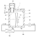
- wiring 2a is connected to the electronic device 2 of the second embodiment.
- the wiring 2a functions as a transmission path for power supply and electrical signals.
- Wiring 2 a is provided so as to extend from cooling tank 10 to connecting portion 30 and liquid storage tank 20 .
- the wiring 2a is taken out from the air opening 21 of the liquid storage tank 20 to the outside.
- the wiring 2a of the electronic device 2 is taken out to the outside using the atmospheric opening 21 open to the atmosphere. Therefore, the wiring 2a of the electronic device 2 can be taken out to the outside without providing a sealing structure for preventing the refrigerant liquid 11 from flowing out to the outside.
- the cooling bath side opening 31 of the connecting portion 30 is positioned above the electronic device 2 in the gravitational direction. That is, the height H2 in the direction of gravity of the opening 31 of the connecting portion 30 on the side of the cooling bath is higher than the height H3 in the direction of gravity of the electronic device 2 .
- the gravity direction height H3 of the electronic device 2 is the height of the upper end portion of the electronic device 2 .
- the liquid level of the refrigerant liquid 11 even if the volume of the gas portion 12 increases, the liquid level of the refrigerant liquid 11 only drops to the cooling tank side opening 31 of the connecting portion 30 . Therefore, the liquid level of the refrigerant liquid 11 is always maintained at a position higher than that of the electronic device 2 . As a result, the electronic device 2 can always be immersed in the coolant liquid 11 without being exposed from the coolant liquid 11, and the cooling capacity of the cooling device 1 can be maintained. Further, when the gas portion 12 reaches the cooling tank side opening 31, excess gas in the gas portion 12 is discharged to the outside from the atmosphere opening 21 of the liquid storage tank 20 through the cooling tank side opening 31. .
- a heat transfer section 13 is provided in the cooling bath 10 of the fourth embodiment.
- the heat transfer part 13 is arranged so as to straddle the refrigerant liquid 11 and the gas part 12 inside the cooling tank 10 , and promotes heat transfer between the refrigerant liquid 11 and the gas part 12 .
- the heat transfer section 13 is fixed to the inner wall side of the upper surface of the cooling bath 10 .
- three heat transfer sections 13 are provided in the example shown in FIG. 4, the number of heat transfer sections 13 can be set arbitrarily, and one or more heat transfer sections 13 may be provided.
- a material with excellent heat transfer coefficient is used as the heat transfer part 13 .
- a metal plate made of aluminum or copper, for example, can be used as the heat transfer portion 13 .
- the gas portion 12 is cooled by the refrigerant liquid 11 via the heat transfer portion 13 .
- the condensation of the gas-phase refrigerant contained in the gas portion 12 can be promoted, and an increase in the volume of the gas portion 12 can be suppressed.
- the plate-like electronic device 2 is arranged horizontally inside the cooling bath 10 . That is, inside the cooling bath 10, the plate surface of the plate-shaped electronic device 2 is arranged so as to intersect with the direction of gravity.
- the cooling tank 10 and the liquid storage tank 20 are connected by the connecting portion 30, and the height H2 in the gravity direction of the cooling tank side opening 31 of the connecting portion 30 is the refrigerant liquid 11 of the cooling tank 10. is lower than the liquid level height H1 of .
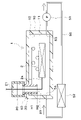
- the liquid storage tank 20 is provided facing the side surface of the cooling tank 10 .
- the connection part 30 of the sixth embodiment is provided so as to penetrate the side surface of the cooling tank 10, and the cooling tank side opening 31 is opened in the horizontal direction.
- the liquid level of the refrigerant liquid 11 in the liquid storage tank 20 is higher than the liquid level of the refrigerant liquid 11 in the cooling tank 10 .
- a gap is provided between the side surface of the cooling tank 10 and the liquid storage tank 20 , and this gap serves as a heat insulating portion 40 .
- the cooling tank 10 and the liquid storage tank 20 are connected by the connecting portion 30, and the height H2 in the gravity direction of the cooling tank side opening 31 of the connecting portion 30 is the refrigerant liquid 11 of the cooling tank 10. is lower than the liquid level height H1 of .
- the cooling tank side opening 31 of the connection part 30 is opened in the horizontal direction, and the cooling tank side opening 31 is open downward in the direction of gravity. It is difficult for air bubbles composed of the phase refrigerant to flow into the cooling tank side opening 31 . As a result, the vapor-phase refrigerant generated inside the cooling tank 10 can be suppressed from flowing out of the atmosphere opening 21 of the liquid storage tank 20 through the cooling tank side opening 31, and the decrease in the refrigerant liquid 11 can be suppressed. can.
- the electronic device 2 is immersed in the refrigerant liquid 11 in the cooling tank 10 to be cooled.
- the heating element to be cooled may be any object that generates heat and can be cooled by being immersed in the refrigerant liquid 11 .
- an evaporation inhibitor may be provided on the upper surface of the refrigerant liquid 11 in the liquid storage tank 20 .
- the upper surface of the refrigerant liquid 11 in the liquid storage tank 20 is the contact surface with the atmosphere.
- the anti-evaporation agent is sufficient as long as it can suppress the evaporation of the refrigerant liquid 11.
- oil for an oil film covering the upper surface of the refrigerant liquid 11 in the liquid storage tank 20, particles covering the upper surface of the refrigerant liquid 11 in the liquid storage tank 20, or the like can be used. can be done.
- the heat transfer section 13 is provided to promote heat transfer between the refrigerant liquid 11 and the gas section 12, but the heat transfer section 13 may have a different configuration.
- the heat transfer section 13 may be provided so as to straddle the atmosphere and the gas section 12 , and the heat transfer section 13 may promote heat transfer between the atmosphere and the gas section 12 to cool the gas section 12 .
- the heat transfer section 13 may be exposed to the outside of the cooling tank 10 , and the heat transfer section 13 may be provided so as to straddle the outside and the inside of the cooling tank 10 .
- the cooling tank side opening 31 of the connection part 30 is opened downward in the direction of gravity in the first to fifth embodiments, and is opened horizontally in the sixth embodiment. 31 may be opened upward in the direction of gravity.
- air bubbles made of the gaseous refrigerant are less likely to flow into the cooling tank side opening 31, and the gaseous refrigerant is prevented from flowing out of the atmosphere opening 21 of the liquid storage tank 20 through the cooling tank side opening 31. can be suppressed, and the decrease in the refrigerant liquid 11 can be suppressed.
- a gap is provided between the cooling tank 10 and the liquid storage tank 20 to form the heat insulation part 40 composed of an air layer.
- the heat insulating part 40 may be configured by providing a heat insulating member.
Landscapes
- Engineering & Computer Science (AREA)
- Microelectronics & Electronic Packaging (AREA)
- Physics & Mathematics (AREA)
- Thermal Sciences (AREA)
- Mechanical Engineering (AREA)
- General Engineering & Computer Science (AREA)
- Chemical & Material Sciences (AREA)
- Life Sciences & Earth Sciences (AREA)
- Sustainable Development (AREA)
- Condensed Matter Physics & Semiconductors (AREA)
- General Physics & Mathematics (AREA)
- Computer Hardware Design (AREA)
- Combustion & Propulsion (AREA)
- Power Engineering (AREA)
- Cooling Or The Like Of Electrical Apparatus (AREA)
- Cooling Or The Like Of Semiconductors Or Solid State Devices (AREA)
Priority Applications (2)
| Application Number | Priority Date | Filing Date | Title |
|---|---|---|---|
| CN202280018954.8A CN116918469A (zh) | 2021-03-10 | 2022-02-11 | 冷却装置 |
| US18/461,375 US20230413482A1 (en) | 2021-03-10 | 2023-09-05 | Cooling device |
Applications Claiming Priority (2)
| Application Number | Priority Date | Filing Date | Title |
|---|---|---|---|
| JP2021037980A JP2022138221A (ja) | 2021-03-10 | 2021-03-10 | 冷却装置 |
| JP2021-037980 | 2021-03-10 |
Related Child Applications (1)
| Application Number | Title | Priority Date | Filing Date |
|---|---|---|---|
| US18/461,375 Continuation US20230413482A1 (en) | 2021-03-10 | 2023-09-05 | Cooling device |
Publications (1)
| Publication Number | Publication Date |
|---|---|
| WO2022190766A1 true WO2022190766A1 (ja) | 2022-09-15 |
Family
ID=83227586
Family Applications (1)
| Application Number | Title | Priority Date | Filing Date |
|---|---|---|---|
| PCT/JP2022/005522 WO2022190766A1 (ja) | 2021-03-10 | 2022-02-11 | 冷却装置 |
Country Status (4)
| Country | Link |
|---|---|
| US (1) | US20230413482A1 (zh) |
| JP (1) | JP2022138221A (zh) |
| CN (1) | CN116918469A (zh) |
| WO (1) | WO2022190766A1 (zh) |
Families Citing this family (2)
| Publication number | Priority date | Publication date | Assignee | Title |
|---|---|---|---|---|
| US20230164952A1 (en) * | 2021-11-24 | 2023-05-25 | Microsoft Technology Licensing, Llc | Systems and methods for recovering fluid in immersion-cooled datacenters |
| WO2024095653A1 (ja) * | 2022-11-02 | 2024-05-10 | ジヤトコ株式会社 | 冷却装置 |
Citations (5)
| Publication number | Priority date | Publication date | Assignee | Title |
|---|---|---|---|---|
| US20130105120A1 (en) * | 2011-10-26 | 2013-05-02 | International Business Machines Corporation | Multi-fluid, two-phase immersion-cooling of electronic component(s) |
| JP2017150715A (ja) * | 2016-02-24 | 2017-08-31 | 富士通株式会社 | 冷却装置及び電子装置 |
| US20170295670A1 (en) * | 2016-04-07 | 2017-10-12 | Hamilton Sundstrand Corporation | Immersion cooled electronic assemblies |
| WO2018020582A1 (ja) * | 2016-07-26 | 2018-02-01 | 富士通株式会社 | 冷却装置及び電子装置 |
| JP2019016764A (ja) * | 2017-07-05 | 2019-01-31 | 富士通株式会社 | 液浸冷却装置及び情報処理装置 |
-
2021
- 2021-03-10 JP JP2021037980A patent/JP2022138221A/ja active Pending
-
2022
- 2022-02-11 CN CN202280018954.8A patent/CN116918469A/zh active Pending
- 2022-02-11 WO PCT/JP2022/005522 patent/WO2022190766A1/ja active Application Filing
-
2023
- 2023-09-05 US US18/461,375 patent/US20230413482A1/en active Pending
Patent Citations (5)
| Publication number | Priority date | Publication date | Assignee | Title |
|---|---|---|---|---|
| US20130105120A1 (en) * | 2011-10-26 | 2013-05-02 | International Business Machines Corporation | Multi-fluid, two-phase immersion-cooling of electronic component(s) |
| JP2017150715A (ja) * | 2016-02-24 | 2017-08-31 | 富士通株式会社 | 冷却装置及び電子装置 |
| US20170295670A1 (en) * | 2016-04-07 | 2017-10-12 | Hamilton Sundstrand Corporation | Immersion cooled electronic assemblies |
| WO2018020582A1 (ja) * | 2016-07-26 | 2018-02-01 | 富士通株式会社 | 冷却装置及び電子装置 |
| JP2019016764A (ja) * | 2017-07-05 | 2019-01-31 | 富士通株式会社 | 液浸冷却装置及び情報処理装置 |
Also Published As
| Publication number | Publication date |
|---|---|
| US20230413482A1 (en) | 2023-12-21 |
| JP2022138221A (ja) | 2022-09-26 |
| CN116918469A (zh) | 2023-10-20 |
Similar Documents
| Publication | Publication Date | Title |
|---|---|---|
| WO2022190766A1 (ja) | 冷却装置 | |
| JP6015675B2 (ja) | 冷却装置及びそれを用いた電子機器 | |
| US9297589B2 (en) | Boiling heat transfer device | |
| WO2011145618A1 (ja) | 沸騰冷却器 | |
| JP6137167B2 (ja) | 冷却装置および冷却システム | |
| JP6285356B2 (ja) | 沸騰冷却装置 | |
| JP6536406B2 (ja) | 電子機器収容装置および電子機器冷却システム | |
| JP6070036B2 (ja) | ループ型サーモサイフォン及び電子機器 | |
| JP2010079401A (ja) | 冷却システム及びそれを用いた電子機器 | |
| JP2013033807A (ja) | 冷却装置およびそれを用いた電子機器 | |
| JP2018133529A (ja) | 冷却装置 | |
| WO2022190868A1 (ja) | 冷却装置 | |
| WO2020255883A1 (ja) | 冷却装置 | |
| JP5860728B2 (ja) | 電子機器の冷却システム | |
| WO2023157717A1 (ja) | 冷却装置 | |
| JP2023149859A (ja) | 冷却装置 | |
| WO2024014024A1 (ja) | 冷却装置 | |
| JP7168850B2 (ja) | 蒸発器及び冷却システム | |
| JP2023135867A (ja) | 冷却装置 | |
| WO2023139989A1 (ja) | 冷却装置 | |
| WO2013073696A1 (ja) | 冷却装置およびそれを用いた電子機器 | |
| JP7537671B2 (ja) | 沸騰冷却装置 | |
| JP2004349652A (ja) | 沸騰冷却装置 | |
| JP2024126263A (ja) | 沸騰冷却装置 | |
| JP2023106287A (ja) | 冷却装置 |
Legal Events
| Date | Code | Title | Description |
|---|---|---|---|
| 121 | Ep: the epo has been informed by wipo that ep was designated in this application |
Ref document number: 22766731 Country of ref document: EP Kind code of ref document: A1 |
|
| WWE | Wipo information: entry into national phase |
Ref document number: 202280018954.8 Country of ref document: CN |
|
| NENP | Non-entry into the national phase |
Ref country code: DE |
|
| 122 | Ep: pct application non-entry in european phase |
Ref document number: 22766731 Country of ref document: EP Kind code of ref document: A1 |