WO2022190766A1 - Cooling device - Google Patents
Cooling device Download PDFInfo
- Publication number
- WO2022190766A1 WO2022190766A1 PCT/JP2022/005522 JP2022005522W WO2022190766A1 WO 2022190766 A1 WO2022190766 A1 WO 2022190766A1 JP 2022005522 W JP2022005522 W JP 2022005522W WO 2022190766 A1 WO2022190766 A1 WO 2022190766A1
- Authority
- WO
- WIPO (PCT)
- Prior art keywords
- cooling
- cooling tank
- refrigerant liquid
- liquid
- tank
- Prior art date
Links
- 238000001816 cooling Methods 0.000 title claims abstract description 207
- 239000007788 liquid Substances 0.000 claims abstract description 253
- 239000003507 refrigerant Substances 0.000 claims abstract description 195
- 230000005484 gravity Effects 0.000 claims abstract description 16
- 238000010438 heat treatment Methods 0.000 claims description 16
- 230000001737 promoting effect Effects 0.000 claims 1
- 239000012071 phase Substances 0.000 description 19
- 238000009835 boiling Methods 0.000 description 17
- 230000007423 decrease Effects 0.000 description 17
- 239000012808 vapor phase Substances 0.000 description 13
- 239000002826 coolant Substances 0.000 description 6
- 238000001704 evaporation Methods 0.000 description 6
- 239000000463 material Substances 0.000 description 4
- 238000011144 upstream manufacturing Methods 0.000 description 4
- 230000008016 vaporization Effects 0.000 description 4
- YCKRFDGAMUMZLT-UHFFFAOYSA-N Fluorine atom Chemical compound [F] YCKRFDGAMUMZLT-UHFFFAOYSA-N 0.000 description 3
- 238000009833 condensation Methods 0.000 description 3
- 230000005494 condensation Effects 0.000 description 3
- 230000008020 evaporation Effects 0.000 description 3
- 229910052731 fluorine Inorganic materials 0.000 description 3
- 239000011737 fluorine Substances 0.000 description 3
- 239000011347 resin Substances 0.000 description 3
- 229920005989 resin Polymers 0.000 description 3
- 230000000630 rising effect Effects 0.000 description 3
- 238000009834 vaporization Methods 0.000 description 3
- 238000004090 dissolution Methods 0.000 description 2
- 230000020169 heat generation Effects 0.000 description 2
- 238000009413 insulation Methods 0.000 description 2
- 238000012986 modification Methods 0.000 description 2
- 230000004048 modification Effects 0.000 description 2
- 238000007789 sealing Methods 0.000 description 2
- 239000003566 sealing material Substances 0.000 description 2
- TXEYQDLBPFQVAA-UHFFFAOYSA-N tetrafluoromethane Chemical compound FC(F)(F)F TXEYQDLBPFQVAA-UHFFFAOYSA-N 0.000 description 2
- RYGMFSIKBFXOCR-UHFFFAOYSA-N Copper Chemical compound [Cu] RYGMFSIKBFXOCR-UHFFFAOYSA-N 0.000 description 1
- 229910052782 aluminium Inorganic materials 0.000 description 1
- XAGFODPZIPBFFR-UHFFFAOYSA-N aluminium Chemical compound [Al] XAGFODPZIPBFFR-UHFFFAOYSA-N 0.000 description 1
- 230000005540 biological transmission Effects 0.000 description 1
- 239000003795 chemical substances by application Substances 0.000 description 1
- 229910052802 copper Inorganic materials 0.000 description 1
- 239000010949 copper Substances 0.000 description 1
- 239000003112 inhibitor Substances 0.000 description 1
- 239000007791 liquid phase Substances 0.000 description 1
- 238000004519 manufacturing process Methods 0.000 description 1
- 229910052751 metal Inorganic materials 0.000 description 1
- 239000002184 metal Substances 0.000 description 1
- 239000007769 metal material Substances 0.000 description 1
- 239000002245 particle Substances 0.000 description 1
- RVZRBWKZFJCCIB-UHFFFAOYSA-N perfluorotributylamine Chemical compound FC(F)(F)C(F)(F)C(F)(F)C(F)(F)N(C(F)(F)C(F)(F)C(F)(F)C(F)(F)F)C(F)(F)C(F)(F)C(F)(F)C(F)(F)F RVZRBWKZFJCCIB-UHFFFAOYSA-N 0.000 description 1
- 238000005057 refrigeration Methods 0.000 description 1
Images


Classifications
-
- H—ELECTRICITY
- H05—ELECTRIC TECHNIQUES NOT OTHERWISE PROVIDED FOR
- H05K—PRINTED CIRCUITS; CASINGS OR CONSTRUCTIONAL DETAILS OF ELECTRIC APPARATUS; MANUFACTURE OF ASSEMBLAGES OF ELECTRICAL COMPONENTS
- H05K7/00—Constructional details common to different types of electric apparatus
- H05K7/20—Modifications to facilitate cooling, ventilating, or heating
- H05K7/2029—Modifications to facilitate cooling, ventilating, or heating using a liquid coolant with phase change in electronic enclosures
- H05K7/203—Modifications to facilitate cooling, ventilating, or heating using a liquid coolant with phase change in electronic enclosures by immersion
-
- F—MECHANICAL ENGINEERING; LIGHTING; HEATING; WEAPONS; BLASTING
- F25—REFRIGERATION OR COOLING; COMBINED HEATING AND REFRIGERATION SYSTEMS; HEAT PUMP SYSTEMS; MANUFACTURE OR STORAGE OF ICE; LIQUEFACTION SOLIDIFICATION OF GASES
- F25D—REFRIGERATORS; COLD ROOMS; ICE-BOXES; COOLING OR FREEZING APPARATUS NOT OTHERWISE PROVIDED FOR
- F25D9/00—Devices not associated with refrigerating machinery and not covered by groups F25D1/00 - F25D7/00; Combinations of devices covered by two or more of the groups F25D1/00 - F25D7/00
-
- F—MECHANICAL ENGINEERING; LIGHTING; HEATING; WEAPONS; BLASTING
- F28—HEAT EXCHANGE IN GENERAL
- F28D—HEAT-EXCHANGE APPARATUS, NOT PROVIDED FOR IN ANOTHER SUBCLASS, IN WHICH THE HEAT-EXCHANGE MEDIA DO NOT COME INTO DIRECT CONTACT
- F28D15/00—Heat-exchange apparatus with the intermediate heat-transfer medium in closed tubes passing into or through the conduit walls ; Heat-exchange apparatus employing intermediate heat-transfer medium or bodies
- F28D15/02—Heat-exchange apparatus with the intermediate heat-transfer medium in closed tubes passing into or through the conduit walls ; Heat-exchange apparatus employing intermediate heat-transfer medium or bodies in which the medium condenses and evaporates, e.g. heat pipes
-
- H—ELECTRICITY
- H01—ELECTRIC ELEMENTS
- H01L—SEMICONDUCTOR DEVICES NOT COVERED BY CLASS H10
- H01L23/00—Details of semiconductor or other solid state devices
- H01L23/34—Arrangements for cooling, heating, ventilating or temperature compensation ; Temperature sensing arrangements
- H01L23/42—Fillings or auxiliary members in containers or encapsulations selected or arranged to facilitate heating or cooling
- H01L23/427—Cooling by change of state, e.g. use of heat pipes
-
- H—ELECTRICITY
- H05—ELECTRIC TECHNIQUES NOT OTHERWISE PROVIDED FOR
- H05K—PRINTED CIRCUITS; CASINGS OR CONSTRUCTIONAL DETAILS OF ELECTRIC APPARATUS; MANUFACTURE OF ASSEMBLAGES OF ELECTRICAL COMPONENTS
- H05K7/00—Constructional details common to different types of electric apparatus
- H05K7/20—Modifications to facilitate cooling, ventilating, or heating
- H05K7/2029—Modifications to facilitate cooling, ventilating, or heating using a liquid coolant with phase change in electronic enclosures
- H05K7/20327—Accessories for moving fluid, for connecting fluid conduits, for distributing fluid or for preventing leakage, e.g. pumps, tanks or manifolds
-
- H—ELECTRICITY
- H05—ELECTRIC TECHNIQUES NOT OTHERWISE PROVIDED FOR
- H05K—PRINTED CIRCUITS; CASINGS OR CONSTRUCTIONAL DETAILS OF ELECTRIC APPARATUS; MANUFACTURE OF ASSEMBLAGES OF ELECTRICAL COMPONENTS
- H05K7/00—Constructional details common to different types of electric apparatus
- H05K7/20—Modifications to facilitate cooling, ventilating, or heating
- H05K7/2089—Modifications to facilitate cooling, ventilating, or heating for power electronics, e.g. for inverters for controlling motor
- H05K7/20936—Liquid coolant with phase change
Definitions
- the present disclosure relates to a cooling device that cools a heating element such as an electronic device by immersing it in a refrigerant liquid.
- the refrigerant liquid may decrease due to the vaporization of the refrigerant liquid due to the heat generated by the heating element, resulting in insufficient cooling of the heating element.
- Patent Document 1 a sealed tank containing a sealing material is provided outside a cooling tank in which a heating element is immersed in a refrigerant liquid, and the sealed tank functions as a trap or a seal.
- a device for suppressing the discharge of the generated refrigerant vapor to the outside has been proposed.
- the temperature of the cooling tank becomes higher than that of the sealed tank due to the heat generated by the heating element.
- the refrigerant liquid or the sealing material may overflow from the sealing tank.
- an object of the present disclosure is to suppress decrease in the coolant liquid in the cooling tank in a cooling device including a cooling tank in which a heating element is cooled by being immersed in the coolant liquid.
- the cooling device of the present disclosure includes a cooling tank, a liquid storage tank, and a connector.
- the cooling bath stores a refrigerant liquid for immersing and cooling the heating element.
- the reservoir stores refrigerant liquid outside the cooling tank and has an atmospheric opening open to the atmosphere.
- the connecting portion connects the liquid storage tank and the cooling tank, and allows the refrigerant liquid to pass therethrough.
- the cooling tank side opening formed on the cooling tank side of the connecting portion is positioned below or at the same height as the liquid surface of the refrigerant liquid in the cooling tank in the direction of gravity.
- the gas generated in the cooling bath is stored in the upper part of the cooling bath to form a gas portion.
- Refrigerant liquid flows between the cooling tank and the liquid storage tank via the connecting part according to the volume change of the gas portion.
- the cooling device 1 of the first embodiment includes a cooling tank 10, a liquid storage tank 20 and a connecting portion 30.
- the cooling tank 10, the liquid storage tank 20, and the connecting part 30 can be made of, for example, a resin material or a metal material.
- the cooling bath 10 is a container-shaped member that accommodates the electronic device 2 to be cooled.
- the electronic device 2 is a heating element that generates heat as it operates and requires cooling.
- an electronic board on which a heating element is mounted, an inverter, or the like can be used.
- the electronic device 2 of this embodiment is a plate-like member, and is arranged so that the plate surface is parallel to the direction of gravity.
- the electronic device 2 corresponds to the heating element of the present disclosure.
- a coolant liquid 11 for cooling the electronic device 2 is stored in the cooling bath 10 .
- the electronic device 2 is in a state of being immersed in the refrigerant liquid 11 .
- a fluorine-based inert liquid is used as the refrigerant liquid 11 .
- a fluorine-based inert liquid is a refrigerant liquid that is excellent in insulating properties, heat transfer properties, and stability.
- a low boiling point refrigerant liquid 11 having a boiling point lower than about 120° C. is used.
- fluorine-based inert liquid As the fluorine-based inert liquid, Novec (trade name of 3M Company) having a hydrofluoroether (HFE) structure and Fluorinert (trade name of 3M Company) having a perfluorocarbon (PFC) structure can be used.
- HFE hydrofluoroether
- PFC perfluorocarbon
- the boiling point of the refrigerant liquid 11 is lower than the heat generation temperature of the electronic device 2 .
- the refrigerant liquid 11 having a boiling point lower than the heat generation temperature of the electronic device 2 by about 10 to 20° C. is used. Therefore, the refrigerant liquid 11 can be boiled by the heat generated by the electronic device 2 , and boiling cooling is performed in which the refrigerant liquid 11 boils in the cooling tank 10 and absorbs heat from the electronic device 2 .
- subcooled boiling is performed in which the refrigerant liquid 11 in contact with the electronic device 2 boils, and the refrigerant liquid 11 in the cooling tank 10 boils in a subcooled liquid having a temperature lower than the boiling point.
- the vapor-phase refrigerant generated by boiling the refrigerant liquid 11 condenses and shrinks in the subcooled liquid, but bubbles that cannot be condensed move upward inside the refrigerant liquid 11 .
- the gas generated inside the cooling tank 10 is stored in the upper part of the cooling tank 10 to form the gas portion 12 .
- the gas portion 12 includes gas-phase refrigerant, dissolved gas released from the refrigerant liquid 11, air present in the cooling tank 10 from the beginning, and the like.
- the volume of the gas portion 12 is variable and may become zero.
- the gas-phase refrigerant contained in the gas portion 12 is generated by evaporating the refrigerant liquid 11 inside the cooling tank 10 . Vaporization of the refrigerant liquid 11 includes boiling and evaporation of the refrigerant liquid 11 .
- the gas-phase refrigerant contained in the gas portion 12 becomes the liquid-phase refrigerant liquid 11 by condensing.
- Dissolved gas mainly composed of the atmosphere is dissolved in the refrigerant liquid 11 .
- the dissolved gas contained in the gas portion 12 is generated when the dissolved gas dissolved in the refrigerant liquid 11 is released from the refrigerant liquid 11 .
- the solubility of the gas dissolved in the refrigerant liquid 11 varies depending on the temperature of the refrigerant liquid 11 and the like. As the temperature of the refrigerant liquid 11 rises, the solubility of the dissolved gas decreases and the dissolved gas is released from the refrigerant liquid 11 .
- the dissolved gas released from the refrigerant liquid 11 forms the gas portion 12 together with the gas-phase refrigerant.
- the dissolved gas contained in the gas portion 12 can be dissolved again in the refrigerant liquid 11 due to the temperature drop of the refrigerant liquid 11 .
- the liquid storage tank 20 is a container-like member capable of storing the refrigerant liquid 11 inside.
- the liquid storage tank 20 is provided outside the cooling tank 10 .
- the liquid storage tank 20 is provided facing the upper surface of the cooling tank 10 .
- An air opening 21 is provided at the top of the liquid storage tank 20 .
- the inside of the liquid storage tank 20 communicates with the atmosphere via an air opening 21 from above.
- the liquid storage tank 20 is open to the atmosphere, and the atmosphere exists above the refrigerant liquid 11 inside the liquid storage tank 20 .
- the liquid storage tank 20 is connected to the cooling tank 10 by a connecting portion 30 .
- the connecting portion 30 is a tubular member, through which the refrigerant liquid 11 can pass.
- the connecting portion 30 has one end connected to the cooling tank 10 and the other end connected to the liquid storage tank 20 .
- the connection part 30 of this embodiment is provided so as to penetrate the upper surface of the cooling bath 10 .
- the inside of the liquid storage tank 20 communicates with the cooling tank 10 through the connecting part 30 below. Since the inside of the liquid storage tank 20 is open to the atmosphere through the atmospheric opening 21, the inside of the liquid storage tank 20 and the inside of the cooling tank 10 are maintained at atmospheric pressure. In other words, the cooling device 1 of this embodiment is open to the atmosphere.
- a cooling tank side opening 31 is formed in the connecting part 30 on the cooling tank 10 side.
- the cooling tank side opening 31 is provided at the lower end portion of the connecting portion 30 in the gravitational direction, and the cooling tank side opening 31 opens downward in the gravitational direction.
- the liquid surface of the refrigerant liquid 11 in the cooling tank 10 is normally located above the cooling tank side opening 31, and can descend to the cooling tank side opening 31 when the volume of the gas portion 12 increases. Therefore, the cooling tank side opening 31 is located below or at the same height as the liquid surface of the refrigerant liquid 11 in the cooling tank 10 in the direction of gravity. That is, the gravity direction height H2 of the cooling tank side opening 31 is at a position lower than or at the same position as the liquid level height H1 of the refrigerant liquid 11 .
- the inside of the liquid storage tank 20 communicates with the inside of the cooling tank 10 via the connecting part 30 . Therefore, the refrigerant liquid 11 can flow between the cooling tank 10 and the liquid storage tank 20 via the connecting portion 30 .
- the refrigerant liquid 11 flows between the cooling tank 10 and the liquid storage tank 20 according to the volume change of the gas portion 12 .
- the volume of the refrigerant liquid 11 in the cooling tank 10 and the volume of the refrigerant liquid 11 in the liquid storage tank 20 interlock and fluctuate. Specifically, when the volume of the refrigerant liquid 11 in the cooling tank 10 decreases, the volume of the refrigerant liquid 11 in the liquid storage tank 20 increases. The volume of refrigerant liquid 11 decreases.
- the cooling tank 10 and the liquid storage tank 20 are not in contact with each other, and a gap is formed between the cooling tank 10 and the liquid storage tank 20 .
- An air layer formed by a gap formed between the cooling tank 10 and the liquid storage tank 20 constitutes a heat insulating portion 40 .
- the heat insulation part 40 suppresses heat transfer between the cooling tank 10 and the liquid storage tank 20 .
- a circulation circuit 50 for circulating the refrigerant liquid 11 in the cooling tank 10 is connected to the cooling tank 10 .
- a circulation pump 51 and a heat exchanger 52 are provided in the circulation circuit 50 .
- the circulation pump 51 pressurizes the refrigerant liquid 11 and circulates it in the circulation circuit 50 .
- the heat exchanger 52 radiates heat from the refrigerant liquid 11 to cool it.
- a radiator that cools the refrigerant liquid 11 by exchanging heat with the outside air, or a chiller that cools the refrigerant liquid 11 by exchanging heat with the low-temperature refrigerant of the refrigeration cycle, or the like can be used.
- the circulation circuit 50 is connected to the cooling tank 10 at a circulation circuit inlet portion 53 and a circulation circuit outlet portion 54 .
- the refrigerant liquid 11 in the cooling bath 10 flows into the circulation circuit 50 through the circulation circuit inlet portion 53 .
- the refrigerant liquid 11 that has circulated through the circulation circuit 50 flows out to the cooling bath 10 through the circulation circuit outlet portion 54 .
- a flow of the refrigerant liquid 11 is formed from the circulation circuit outlet portion 54 toward the circulation circuit inlet portion 53 .
- the circulation circuit outlet portion 54 is provided on the left side of the cooling bath 10 and the circulation circuit inlet portion 53 is provided on the right side of the cooling bath 10 . Therefore, a flow of the refrigerant liquid 11 from left to right is formed inside the cooling tank 10 .
- the cooling tank side opening 31 of the connecting portion 30 described above is provided at a position where it is difficult for the gas-phase refrigerant to flow.
- the cooling tank side opening 31 is provided on the upstream side of the cooling tank 10 in the flow direction of the refrigerant liquid 11 . That is, the cooling tank side opening 31 is provided closer to the circulation circuit outlet 54 than the circulation circuit inlet 53 in the flow direction of the refrigerant liquid 11 .
- the heat generated by the electronic device 2 boils the refrigerant liquid 11 in the vicinity of the electronic device 2, generating a vapor phase refrigerant.
- the gas-phase refrigerant turns into bubbles and rises inside the cooling tank 10 to form the gas portion 12 .
- the dissolved gas released from the refrigerant liquid 11 due to the temperature rise of the refrigerant liquid 11 also forms the gas portion 12 together with the gas-phase refrigerant.
- the vapor-phase refrigerant obtained by vaporizing the refrigerant liquid 11 and the dissolved gas released from the refrigerant liquid 11 are stored inside the cooling tank 10 .
- the vapor-phase refrigerant generated by boiling rises in the refrigerant liquid 11 as bubbles. Since the refrigerant liquid 11 in the cooling tank 10 is a sub-cooled liquid, the air bubbles made of the vapor-phase refrigerant are cooled by the refrigerant liquid 11 when rising inside the refrigerant liquid 11, and the vapor-phase refrigerant is condensed. As a result, the bubbles made of the gas-phase refrigerant shrink while rising inside the refrigerant liquid 11, and when the degree of subcooling of the refrigerant liquid 11 is large, the bubbles disappear.
- the refrigerant liquid 11 in the cooling tank 10 is supplied to the heat exchanger 52 via the circulation circuit 50 and cooled in the heat exchanger 52 . Cooling by the heat exchanger 52 can positively maintain the subcooled state of the refrigerant liquid 11 .
- the volume of the gas portion 12 increases due to vaporization of the refrigerant liquid 11 and release of dissolved gas from the refrigerant liquid 11 .
- the volume of the refrigerant liquid 11 inside the cooling tank 10 decreases.
- the refrigerant liquid 11 flows from the cooling tank 10 to the liquid storage tank 20 and the volume of the refrigerant liquid 11 inside the liquid storage tank 20 increases.
- the temperature of the refrigerant liquid 11 is lowered by reducing the amount of heat generated by the electronic equipment 2, increasing the cooling capacity of the heat exchanger 52, and the like.
- the decrease in the temperature of the refrigerant liquid 11 promotes condensation of the gas-phase refrigerant contained in the gas portion 12 and promotes dissolution of the dissolved gas contained in the gas portion 12 into the refrigerant liquid 11 .
- the volume of the gas portion 12 decreases due to the condensation of the gas-phase refrigerant contained in the gas portion 12 and the dissolution of the dissolved gas contained in the gas portion 12 into the refrigerant liquid 11, and the volume of the refrigerant liquid 11 decreases. increases. As the volume of the refrigerant liquid 11 increases, the refrigerant liquid 11 flows from the liquid storage tank 20 to the cooling tank 10 , and the volume of the refrigerant liquid 11 inside the liquid storage tank 20 decreases.
- the cooling tank side opening 31 of the connecting part 30 is positioned below or at the same height as the liquid surface of the refrigerant liquid 11 in the cooling tank 10 in the gravitational direction. Furthermore, the gas generated in the cooling tank 10 is stored in the upper part of the cooling tank 10 to form the gas part 12, and according to the volume change of the gas part 12, the cooling tank 10 and the storage liquid via the connection part 30 Refrigerant liquid 11 flows between tank 20 . As a result, it is possible to prevent the gas-phase refrigerant from flowing out from the atmosphere opening 21 of the liquid storage tank 20 via the connecting portion 30 . As a result, even if the cooling device 1 is used for a long period of time, the reduction of the refrigerant liquid 11 in the cooling tank 10 can be suppressed.
- the air-open type cooling device 1 having the air opening 21 communicating with the atmosphere is used.
- the reduction of the refrigerant liquid 11 in the cooling tank 10 can be suppressed without using a pressure-resistant container for enclosing the refrigerant liquid 11 . Therefore, the cooling device 1 can be downsized.
- boiling cooling is performed in which the heat generated by the electronic device 2 causes the refrigerant liquid 11 to boil.
- the electronic device 2 can be efficiently cooled, but on the other hand, a large amount of gaseous refrigerant is generated, and the gaseous refrigerant tends to flow out to the outside. According to the present embodiment, even in the cooling device 1 that performs boiling cooling in which the refrigerant liquid 11 boils, the decrease in the refrigerant liquid 11 can be effectively suppressed.
- the refrigerant liquid 11 in the cooling tank 10 is a subcooled liquid, and subcooled boiling is performed. Therefore, the vapor-phase refrigerant generated by the boiling of the refrigerant liquid 11 due to the heat generated by the electronic device 2 is cooled and condensed by the refrigerant liquid 11 made of the subcooled liquid. As a result, the gas-phase refrigerant can be suppressed from flowing through the circulation circuit 50 to the circulation pump 51 and the heat exchanger 52, and the performance of the circulation pump 51 and the heat exchanger 52 can be maintained, so that they can be used stably. can.
- the refrigerant liquid 11 in the cooling tank 10 is circulated by the circulation circuit 50 and the refrigerant liquid 11 is cooled by the heat exchanger 52 .
- the temperature rise of the refrigerant liquid 11 can be suppressed, and the vapor-phase refrigerant can be effectively cooled by the refrigerant liquid 11 in a subcooled state.
- an increase in the volume of the gas portion 12 can be suppressed, and a decrease in the liquid level of the refrigerant liquid 11 in the cooling tank 10 and an increase in the liquid level of the refrigerant liquid 11 in the liquid storage tank 20 can be suppressed.
- the cooling tank side opening 31 of the connecting portion 30 is provided on the upstream side of the cooling tank 10 in the coolant flow direction. Since the bubbles made of the gas-phase refrigerant rise while moving downstream in the flow direction of the refrigerant liquid 11 , they rise while moving away from the cooling tank side opening 31 . Therefore, it is possible to suppress the gas-phase refrigerant from flowing into the cooling tank side opening 31 provided on the upstream side of the cooling tank 10 in the refrigerant flow direction. As a result, the vapor-phase refrigerant generated inside the cooling tank 10 can be suppressed from flowing out of the atmosphere opening 21 of the liquid storage tank 20 through the cooling tank side opening 31, and the decrease in the refrigerant liquid 11 can be suppressed. can.
- a heat insulating section 40 is provided between the cooling tank 10 and the liquid storage tank 20 .
- heat transfer from the cooling tank 10 to the liquid storage tank 20 can be suppressed, and the refrigerant liquid 11 can be prevented from evaporating in the liquid storage tank 20 and flowing out to the outside.
- the cooling tank 10, the liquid storage tank 20, and the connecting portion 30 are made of a resin material.
- the size and weight of the cooling tank 10 and the like can be reduced, the manufacturing cost of the cooling tank 10 and the like can be reduced, and the degree of freedom in the shape of the cooling tank 10 and the like can be increased.
- the cooling tank 10, the liquid storage tank 20, and the connection part 30 from a resin material, heat transfer from the cooling tank 10 to the liquid storage tank 20 can be suppressed, and the refrigerant liquid 11 evaporates in the liquid storage tank 20. can be suppressed from leaking to the outside.
- wiring 2a is connected to the electronic device 2 of the second embodiment.
- the wiring 2a functions as a transmission path for power supply and electrical signals.
- Wiring 2 a is provided so as to extend from cooling tank 10 to connecting portion 30 and liquid storage tank 20 .
- the wiring 2a is taken out from the air opening 21 of the liquid storage tank 20 to the outside.
- the wiring 2a of the electronic device 2 is taken out to the outside using the atmospheric opening 21 open to the atmosphere. Therefore, the wiring 2a of the electronic device 2 can be taken out to the outside without providing a sealing structure for preventing the refrigerant liquid 11 from flowing out to the outside.
- the cooling bath side opening 31 of the connecting portion 30 is positioned above the electronic device 2 in the gravitational direction. That is, the height H2 in the direction of gravity of the opening 31 of the connecting portion 30 on the side of the cooling bath is higher than the height H3 in the direction of gravity of the electronic device 2 .
- the gravity direction height H3 of the electronic device 2 is the height of the upper end portion of the electronic device 2 .
- the liquid level of the refrigerant liquid 11 even if the volume of the gas portion 12 increases, the liquid level of the refrigerant liquid 11 only drops to the cooling tank side opening 31 of the connecting portion 30 . Therefore, the liquid level of the refrigerant liquid 11 is always maintained at a position higher than that of the electronic device 2 . As a result, the electronic device 2 can always be immersed in the coolant liquid 11 without being exposed from the coolant liquid 11, and the cooling capacity of the cooling device 1 can be maintained. Further, when the gas portion 12 reaches the cooling tank side opening 31, excess gas in the gas portion 12 is discharged to the outside from the atmosphere opening 21 of the liquid storage tank 20 through the cooling tank side opening 31. .
- a heat transfer section 13 is provided in the cooling bath 10 of the fourth embodiment.
- the heat transfer part 13 is arranged so as to straddle the refrigerant liquid 11 and the gas part 12 inside the cooling tank 10 , and promotes heat transfer between the refrigerant liquid 11 and the gas part 12 .
- the heat transfer section 13 is fixed to the inner wall side of the upper surface of the cooling bath 10 .
- three heat transfer sections 13 are provided in the example shown in FIG. 4, the number of heat transfer sections 13 can be set arbitrarily, and one or more heat transfer sections 13 may be provided.
- a material with excellent heat transfer coefficient is used as the heat transfer part 13 .
- a metal plate made of aluminum or copper, for example, can be used as the heat transfer portion 13 .
- the gas portion 12 is cooled by the refrigerant liquid 11 via the heat transfer portion 13 .
- the condensation of the gas-phase refrigerant contained in the gas portion 12 can be promoted, and an increase in the volume of the gas portion 12 can be suppressed.
- the plate-like electronic device 2 is arranged horizontally inside the cooling bath 10 . That is, inside the cooling bath 10, the plate surface of the plate-shaped electronic device 2 is arranged so as to intersect with the direction of gravity.
- the cooling tank 10 and the liquid storage tank 20 are connected by the connecting portion 30, and the height H2 in the gravity direction of the cooling tank side opening 31 of the connecting portion 30 is the refrigerant liquid 11 of the cooling tank 10. is lower than the liquid level height H1 of .
- the liquid storage tank 20 is provided facing the side surface of the cooling tank 10 .
- the connection part 30 of the sixth embodiment is provided so as to penetrate the side surface of the cooling tank 10, and the cooling tank side opening 31 is opened in the horizontal direction.
- the liquid level of the refrigerant liquid 11 in the liquid storage tank 20 is higher than the liquid level of the refrigerant liquid 11 in the cooling tank 10 .
- a gap is provided between the side surface of the cooling tank 10 and the liquid storage tank 20 , and this gap serves as a heat insulating portion 40 .
- the cooling tank 10 and the liquid storage tank 20 are connected by the connecting portion 30, and the height H2 in the gravity direction of the cooling tank side opening 31 of the connecting portion 30 is the refrigerant liquid 11 of the cooling tank 10. is lower than the liquid level height H1 of .
- the cooling tank side opening 31 of the connection part 30 is opened in the horizontal direction, and the cooling tank side opening 31 is open downward in the direction of gravity. It is difficult for air bubbles composed of the phase refrigerant to flow into the cooling tank side opening 31 . As a result, the vapor-phase refrigerant generated inside the cooling tank 10 can be suppressed from flowing out of the atmosphere opening 21 of the liquid storage tank 20 through the cooling tank side opening 31, and the decrease in the refrigerant liquid 11 can be suppressed. can.
- the electronic device 2 is immersed in the refrigerant liquid 11 in the cooling tank 10 to be cooled.
- the heating element to be cooled may be any object that generates heat and can be cooled by being immersed in the refrigerant liquid 11 .
- an evaporation inhibitor may be provided on the upper surface of the refrigerant liquid 11 in the liquid storage tank 20 .
- the upper surface of the refrigerant liquid 11 in the liquid storage tank 20 is the contact surface with the atmosphere.
- the anti-evaporation agent is sufficient as long as it can suppress the evaporation of the refrigerant liquid 11.
- oil for an oil film covering the upper surface of the refrigerant liquid 11 in the liquid storage tank 20, particles covering the upper surface of the refrigerant liquid 11 in the liquid storage tank 20, or the like can be used. can be done.
- the heat transfer section 13 is provided to promote heat transfer between the refrigerant liquid 11 and the gas section 12, but the heat transfer section 13 may have a different configuration.
- the heat transfer section 13 may be provided so as to straddle the atmosphere and the gas section 12 , and the heat transfer section 13 may promote heat transfer between the atmosphere and the gas section 12 to cool the gas section 12 .
- the heat transfer section 13 may be exposed to the outside of the cooling tank 10 , and the heat transfer section 13 may be provided so as to straddle the outside and the inside of the cooling tank 10 .
- the cooling tank side opening 31 of the connection part 30 is opened downward in the direction of gravity in the first to fifth embodiments, and is opened horizontally in the sixth embodiment. 31 may be opened upward in the direction of gravity.
- air bubbles made of the gaseous refrigerant are less likely to flow into the cooling tank side opening 31, and the gaseous refrigerant is prevented from flowing out of the atmosphere opening 21 of the liquid storage tank 20 through the cooling tank side opening 31. can be suppressed, and the decrease in the refrigerant liquid 11 can be suppressed.
- a gap is provided between the cooling tank 10 and the liquid storage tank 20 to form the heat insulation part 40 composed of an air layer.
- the heat insulating part 40 may be configured by providing a heat insulating member.
Abstract
The present invention comprises: a cooling tank (10) that stores a refrigerant liquid (11) for immersing and cooling a heat generating body (2); a liquid storage tank (20) that stores the refrigerant liquid outside of the cooling tank and has a vent opening (21) that is open to the air; and a connecting section (30) that connects the liquid storage tank and the cooling tank and is configured such that the refrigerant liquid can pass therethrough. A cooling tank-side opening (31) formed on the cooling tank side of the connecting section is positioned below or at the same height as the liquid surface of the refrigerant liquid in the cooling tank in the direction of gravity. A gas generated in the cooling tank accumulates in the upper section of the cooling tank and forms a gas section (12). The refrigerant liquid flows between the cooling tank and the liquid storage tank via the connecting section in response to changes in the volume of the gas section.
Description
本出願は、2021年3月10日に出願された日本特許出願番号2021-37980号に基づくもので、ここにその記載内容を援用する。
This application is based on Japanese Patent Application No. 2021-37980 filed on March 10, 2021, and the contents thereof are incorporated herein.
本開示は、電子機器等の発熱体を冷媒液に浸漬して冷却する冷却装置に関する。
The present disclosure relates to a cooling device that cools a heating element such as an electronic device by immersing it in a refrigerant liquid.
電子機器等の発熱体を冷媒液に浸漬して冷却する冷却装置では、発熱体の発熱で冷媒液が気化すること等によって冷媒液が減少し、発熱体の冷却不足を招く恐れがある。
In a cooling device that cools a heating element such as an electronic device by immersing it in a refrigerant liquid, the refrigerant liquid may decrease due to the vaporization of the refrigerant liquid due to the heat generated by the heating element, resulting in insufficient cooling of the heating element.
これに対し、特許文献1では、発熱体を冷媒液に浸漬する冷却槽の外部に封止材を収容する封止槽を設け、封止槽をトラップ又はシールとして機能させることで、冷却槽で発生する冷媒蒸気の外部への排出を抑える装置が提案されている。
On the other hand, in Patent Document 1, a sealed tank containing a sealing material is provided outside a cooling tank in which a heating element is immersed in a refrigerant liquid, and the sealed tank functions as a trap or a seal. A device for suppressing the discharge of the generated refrigerant vapor to the outside has been proposed.
しかしながら、発熱体の発熱によって冷却槽の温度は封止槽よりも高くなることから、冷却槽で蒸発した冷媒液が封止槽で凝縮することが継続すると、いずれは封止槽が液で満たされ、封止槽から冷媒液もしくは封止材が外部へ溢れ出るおそれがある。
However, the temperature of the cooling tank becomes higher than that of the sealed tank due to the heat generated by the heating element. As a result, the refrigerant liquid or the sealing material may overflow from the sealing tank.
本開示は上記点に鑑み、冷媒液に発熱体を浸漬して冷却する冷却槽を備える冷却装置において、冷却槽における冷媒液減少を抑制することを目的とする。
In view of the above points, an object of the present disclosure is to suppress decrease in the coolant liquid in the cooling tank in a cooling device including a cooling tank in which a heating element is cooled by being immersed in the coolant liquid.
上記目的を達成するため、本開示の冷却装置は、冷却槽と、貯液槽と、接続部とを備える。冷却槽は、発熱体を浸漬して冷却するための冷媒液を貯蔵する。貯液槽は、冷却槽の外部で冷媒液を貯蔵するとともに、大気に開放する大気開口部を有する。接続部は、貯液槽と冷却槽とを接続し、冷媒液が通過可能となっている。
In order to achieve the above object, the cooling device of the present disclosure includes a cooling tank, a liquid storage tank, and a connector. The cooling bath stores a refrigerant liquid for immersing and cooling the heating element. The reservoir stores refrigerant liquid outside the cooling tank and has an atmospheric opening open to the atmosphere. The connecting portion connects the liquid storage tank and the cooling tank, and allows the refrigerant liquid to pass therethrough.
接続部のうち冷却槽側に形成された冷却槽側開口部は、重力方向において、冷却槽内で冷媒液の液面の下側又は同じ高さに位置している。冷却槽内で発生した気体は冷却槽内の上部で貯留されて気体部を形成する。気体部の体積変動に応じて、接続部を介して冷却槽と貯液槽との間を冷媒液が流動する。
The cooling tank side opening formed on the cooling tank side of the connecting portion is positioned below or at the same height as the liquid surface of the refrigerant liquid in the cooling tank in the direction of gravity. The gas generated in the cooling bath is stored in the upper part of the cooling bath to form a gas portion. Refrigerant liquid flows between the cooling tank and the liquid storage tank via the connecting part according to the volume change of the gas portion.
これにより、気相冷媒が接続部を介して貯液槽の大気開口部から外部に流出することを抑制できる。この結果、冷却槽の冷媒液が減少することを抑制できる。
As a result, it is possible to suppress the gas-phase refrigerant from flowing out of the air opening of the liquid storage tank through the connecting portion. As a result, it is possible to suppress the decrease of the refrigerant liquid in the cooling tank.
以下に、図面を参照しながら本開示を実施するための複数の形態を説明する。各形態において先行する形態で説明した事項に対応する部分には同一の参照符号を付して重複する説明を省略する場合がある。各形態において構成の一部のみを説明している場合は、構成の他の部分については先行して説明した他の形態を適用することができる。各実施形態で具体的に組合せが可能であることを明示している部分同士の組合せばかりではなく、特に組合せに支障が生じなければ、明示してなくとも実施形態同士を部分的に組み合せることも可能である。
A plurality of modes for carrying out the present disclosure will be described below with reference to the drawings. In each form, the same reference numerals may be given to the parts corresponding to the matters described in the preceding form, and overlapping explanations may be omitted. When only a part of the configuration is described in each form, the previously described other forms can be applied to other parts of the configuration. Not only the combination of the parts that are specifically stated that the combination is possible in each embodiment, but also the partial combination of the embodiments even if it is not specified unless there is a particular problem with the combination. is also possible.
(第1実施形態)
以下、本開示の第1実施形態について図面に基づいて説明する。図1では、紙面上下方向が重力方向となっている。 (First embodiment)
A first embodiment of the present disclosure will be described below with reference to the drawings. In FIG. 1, the vertical direction of the paper is the direction of gravity.
以下、本開示の第1実施形態について図面に基づいて説明する。図1では、紙面上下方向が重力方向となっている。 (First embodiment)
A first embodiment of the present disclosure will be described below with reference to the drawings. In FIG. 1, the vertical direction of the paper is the direction of gravity.
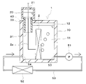
図1に示すように、本第1実施形態の冷却装置1は、冷却槽10、貯液槽20および接続部30を備えている。冷却槽10、貯液槽20および接続部30は、例えば樹脂材料や金属材料によって構成することができる。
As shown in FIG. 1, the cooling device 1 of the first embodiment includes a cooling tank 10, a liquid storage tank 20 and a connecting portion 30. The cooling tank 10, the liquid storage tank 20, and the connecting part 30 can be made of, for example, a resin material or a metal material.
冷却槽10は、冷却対象である電子機器2が収容された容器状部材である。電子機器2は、作動に伴って発熱し、冷却を必要とする発熱体である。電子機器2としては、例えば発熱素子が搭載された電子基板やインバータ等を用いることができる。本実施形態の電子機器2は板状部材であり、板面が重力方向と平行となるように配置されている。電子機器2が本開示の発熱体に相当している。
The cooling bath 10 is a container-shaped member that accommodates the electronic device 2 to be cooled. The electronic device 2 is a heating element that generates heat as it operates and requires cooling. As the electronic device 2, for example, an electronic board on which a heating element is mounted, an inverter, or the like can be used. The electronic device 2 of this embodiment is a plate-like member, and is arranged so that the plate surface is parallel to the direction of gravity. The electronic device 2 corresponds to the heating element of the present disclosure.
冷却槽10には、電子機器2を冷却するための冷媒液11が貯蔵されている。電子機器2は、冷媒液11に浸漬した状態となっている。本実施形態では、冷媒液11としてフッ素系不活性液体を用いている。フッ素系不活性液体は、絶縁性、伝熱特性、安定性に優れた冷媒液である。本実施形態では、沸点が120℃程度よりも低い低沸点の冷媒液11を用いている。フッ素系不活性液体としては、例えばハイドロフルオロエーテル(HFE)構造を有するノベック(3M社の商品名)やパーフルオロカーボン(PFC)構造を有するフロリナート(3M社の商品名)を用いることができる。
A coolant liquid 11 for cooling the electronic device 2 is stored in the cooling bath 10 . The electronic device 2 is in a state of being immersed in the refrigerant liquid 11 . In this embodiment, a fluorine-based inert liquid is used as the refrigerant liquid 11 . A fluorine-based inert liquid is a refrigerant liquid that is excellent in insulating properties, heat transfer properties, and stability. In this embodiment, a low boiling point refrigerant liquid 11 having a boiling point lower than about 120° C. is used. As the fluorine-based inert liquid, Novec (trade name of 3M Company) having a hydrofluoroether (HFE) structure and Fluorinert (trade name of 3M Company) having a perfluorocarbon (PFC) structure can be used.
冷媒液11の沸点は、電子機器2の発熱温度よりも低くなっている。本実施形態では、電子機器2の発熱温度よりも10~20℃程度低い沸点を有する冷媒液11を用いている。このため、電子機器2の発熱で冷媒液11は沸騰可能となっており、冷却槽10では冷媒液11が沸騰して電子機器2から吸熱する沸騰冷却が行われる。本実施形態では、電子機器2と接触する冷媒液11が沸騰し、冷却槽10の冷媒液11が沸点より低温のサブクール液となっている状態で沸騰するサブクール沸騰が行われる。
The boiling point of the refrigerant liquid 11 is lower than the heat generation temperature of the electronic device 2 . In this embodiment, the refrigerant liquid 11 having a boiling point lower than the heat generation temperature of the electronic device 2 by about 10 to 20° C. is used. Therefore, the refrigerant liquid 11 can be boiled by the heat generated by the electronic device 2 , and boiling cooling is performed in which the refrigerant liquid 11 boils in the cooling tank 10 and absorbs heat from the electronic device 2 . In this embodiment, subcooled boiling is performed in which the refrigerant liquid 11 in contact with the electronic device 2 boils, and the refrigerant liquid 11 in the cooling tank 10 boils in a subcooled liquid having a temperature lower than the boiling point.
冷媒液11が沸騰して発生した気相冷媒はサブクール液で凝縮、縮小するが、凝縮できない気泡が冷媒液11の内部を上方に移動する。冷却槽10の内部で発生した気体が冷却槽10内の上部で貯留されることで気体部12が形成される。気体部12には、気相冷媒、冷媒液11から放出された溶存ガス、初期から冷却槽10に存在する空気などが含まれている。気体部12の体積は変動可能となっており、体積ゼロになることもある。
The vapor-phase refrigerant generated by boiling the refrigerant liquid 11 condenses and shrinks in the subcooled liquid, but bubbles that cannot be condensed move upward inside the refrigerant liquid 11 . The gas generated inside the cooling tank 10 is stored in the upper part of the cooling tank 10 to form the gas portion 12 . The gas portion 12 includes gas-phase refrigerant, dissolved gas released from the refrigerant liquid 11, air present in the cooling tank 10 from the beginning, and the like. The volume of the gas portion 12 is variable and may become zero.
気体部12に含まれる気相冷媒は、冷却槽10の内部で冷媒液11が気化することで生成される。冷媒液11の気化には、冷媒液11の沸騰と蒸発が含まれている。気体部12に含まれる気相冷媒は、凝縮することで液相の冷媒液11となる。
The gas-phase refrigerant contained in the gas portion 12 is generated by evaporating the refrigerant liquid 11 inside the cooling tank 10 . Vaporization of the refrigerant liquid 11 includes boiling and evaporation of the refrigerant liquid 11 . The gas-phase refrigerant contained in the gas portion 12 becomes the liquid-phase refrigerant liquid 11 by condensing.
冷媒液11には、主に大気からなる溶存ガスが溶解している。気体部12に含まれる溶存ガスは、冷媒液11に溶解している溶存ガスが冷媒液11から放出されることで生成する。冷媒液11に溶解している溶存ガスの溶解度は、冷媒液11の温度等によって変動する。冷媒液11の温度が上昇すると溶存ガスの溶解度が低下し、溶存ガスが冷媒液11から放出される。冷媒液11から放出された溶存ガスは気相冷媒とともに気体部12を形成する。気体部12に含まれる溶存ガスは、冷媒液11の温度低下によって冷媒液11に再度溶解することができる。
Dissolved gas mainly composed of the atmosphere is dissolved in the refrigerant liquid 11 . The dissolved gas contained in the gas portion 12 is generated when the dissolved gas dissolved in the refrigerant liquid 11 is released from the refrigerant liquid 11 . The solubility of the gas dissolved in the refrigerant liquid 11 varies depending on the temperature of the refrigerant liquid 11 and the like. As the temperature of the refrigerant liquid 11 rises, the solubility of the dissolved gas decreases and the dissolved gas is released from the refrigerant liquid 11 . The dissolved gas released from the refrigerant liquid 11 forms the gas portion 12 together with the gas-phase refrigerant. The dissolved gas contained in the gas portion 12 can be dissolved again in the refrigerant liquid 11 due to the temperature drop of the refrigerant liquid 11 .
貯液槽20は、内部に冷媒液11を貯蔵可能な容器状部材である。貯液槽20は、冷却槽10の外部に設けられている。本実施形態では、貯液槽20は、冷却槽10の上面に対向して設けられている。
The liquid storage tank 20 is a container-like member capable of storing the refrigerant liquid 11 inside. The liquid storage tank 20 is provided outside the cooling tank 10 . In this embodiment, the liquid storage tank 20 is provided facing the upper surface of the cooling tank 10 .
貯液槽20の上部には、大気開口部21が設けられている。貯液槽20の内部は、上方で大気開口部21を介して大気と連通している。貯液槽20は大気に開放されており、貯液槽20の内部では、冷媒液11の上部に大気が存在する。
An air opening 21 is provided at the top of the liquid storage tank 20 . The inside of the liquid storage tank 20 communicates with the atmosphere via an air opening 21 from above. The liquid storage tank 20 is open to the atmosphere, and the atmosphere exists above the refrigerant liquid 11 inside the liquid storage tank 20 .
貯液槽20は、接続部30によって冷却槽10と接続されている。接続部30は筒状部材であり、内部を冷媒液11が通過可能となっている。接続部30は、一端側に冷却槽10が接続され、他端側に貯液槽20が接続されている。本実施形態の接続部30は、冷却槽10の上面を貫通するように設けられている。
The liquid storage tank 20 is connected to the cooling tank 10 by a connecting portion 30 . The connecting portion 30 is a tubular member, through which the refrigerant liquid 11 can pass. The connecting portion 30 has one end connected to the cooling tank 10 and the other end connected to the liquid storage tank 20 . The connection part 30 of this embodiment is provided so as to penetrate the upper surface of the cooling bath 10 .
貯液槽20の内部は、下方で接続部30を介して冷却槽10に連通している。貯液槽20の内部は大気開口部21を介して大気に開放していることから、貯液槽20の内部および冷却槽10の内部は大気圧に維持される。つまり、本実施形態の冷却装置1は大気開放式となっている。
The inside of the liquid storage tank 20 communicates with the cooling tank 10 through the connecting part 30 below. Since the inside of the liquid storage tank 20 is open to the atmosphere through the atmospheric opening 21, the inside of the liquid storage tank 20 and the inside of the cooling tank 10 are maintained at atmospheric pressure. In other words, the cooling device 1 of this embodiment is open to the atmosphere.
接続部30のうち冷却槽10側には、冷却槽側開口部31が形成されている。本実施形態では、接続部30の重力方向下端部に冷却槽側開口部31が設けられており、冷却槽側開口部31は重力方向下方に向かって開口している。
A cooling tank side opening 31 is formed in the connecting part 30 on the cooling tank 10 side. In this embodiment, the cooling tank side opening 31 is provided at the lower end portion of the connecting portion 30 in the gravitational direction, and the cooling tank side opening 31 opens downward in the gravitational direction.
冷却槽10内の冷媒液11の液面は、通常は冷却槽側開口部31よりも上方に位置しており、気体部12の体積増大時に冷却槽側開口部31まで下降し得る。このため、冷却槽側開口部31は、重力方向において、冷却槽10内の冷媒液11の液面より下側または同じ高さに位置している。つまり、冷却槽側開口部31の重力方向高さH2が冷媒液11の液面高さH1よりも低い位置あるいは同じ位置になっている。
The liquid surface of the refrigerant liquid 11 in the cooling tank 10 is normally located above the cooling tank side opening 31, and can descend to the cooling tank side opening 31 when the volume of the gas portion 12 increases. Therefore, the cooling tank side opening 31 is located below or at the same height as the liquid surface of the refrigerant liquid 11 in the cooling tank 10 in the direction of gravity. That is, the gravity direction height H2 of the cooling tank side opening 31 is at a position lower than or at the same position as the liquid level height H1 of the refrigerant liquid 11 .
貯液槽20の内部は、接続部30を介して冷却槽10の内部と連通している。このため、冷媒液11は、接続部30を介して冷却槽10と貯液槽20との間を流動可能となっている。冷媒液11は、気体部12の体積変動に応じて、冷却槽10と貯液槽20との間を流動する。
The inside of the liquid storage tank 20 communicates with the inside of the cooling tank 10 via the connecting part 30 . Therefore, the refrigerant liquid 11 can flow between the cooling tank 10 and the liquid storage tank 20 via the connecting portion 30 . The refrigerant liquid 11 flows between the cooling tank 10 and the liquid storage tank 20 according to the volume change of the gas portion 12 .
冷却槽10と貯液槽20との間を冷媒液11が流動することで、冷却槽10の冷媒液11の体積と貯液槽20の冷媒液11の体積は連動して変動する。具体的には、冷却槽10の冷媒液11の体積が減少すると、貯液槽20の冷媒液11の体積が増大し、冷却槽10の冷媒液11の体積が増大すると、貯液槽20の冷媒液11の体積が減少する。
As the refrigerant liquid 11 flows between the cooling tank 10 and the liquid storage tank 20, the volume of the refrigerant liquid 11 in the cooling tank 10 and the volume of the refrigerant liquid 11 in the liquid storage tank 20 interlock and fluctuate. Specifically, when the volume of the refrigerant liquid 11 in the cooling tank 10 decreases, the volume of the refrigerant liquid 11 in the liquid storage tank 20 increases. The volume of refrigerant liquid 11 decreases.
本実施形態では、冷却槽10と貯液槽20が接触しておらず、冷却槽10と貯液槽20の間に隙間が形成されている。冷却槽10と貯液槽20の間に形成された隙間からなる空気層は、断熱部40を構成している。断熱部40は、冷却槽10と貯液槽20の間における熱の移動を抑制する。
In this embodiment, the cooling tank 10 and the liquid storage tank 20 are not in contact with each other, and a gap is formed between the cooling tank 10 and the liquid storage tank 20 . An air layer formed by a gap formed between the cooling tank 10 and the liquid storage tank 20 constitutes a heat insulating portion 40 . The heat insulation part 40 suppresses heat transfer between the cooling tank 10 and the liquid storage tank 20 .
冷却槽10には、冷却槽10内の冷媒液11を循環させる循環回路50が接続されている。循環回路50には、循環ポンプ51と熱交換器52が設けられている。
A circulation circuit 50 for circulating the refrigerant liquid 11 in the cooling tank 10 is connected to the cooling tank 10 . A circulation pump 51 and a heat exchanger 52 are provided in the circulation circuit 50 .
循環ポンプ51は、冷媒液11を圧送して循環回路50に循環させる。熱交換器52は、冷媒液11の熱を放熱して冷却する。熱交換器52としては、例えば冷媒液11を外気と熱交換して冷却するラジエータ、あるいは冷媒液11を冷凍サイクルの低温冷媒と熱交換して冷却するチラー等を用いることができる。熱交換器52で冷媒液11を冷却することで、冷媒液11の温度上昇を抑制することができ、サブクール状態を維持することができる。
The circulation pump 51 pressurizes the refrigerant liquid 11 and circulates it in the circulation circuit 50 . The heat exchanger 52 radiates heat from the refrigerant liquid 11 to cool it. As the heat exchanger 52, for example, a radiator that cools the refrigerant liquid 11 by exchanging heat with the outside air, or a chiller that cools the refrigerant liquid 11 by exchanging heat with the low-temperature refrigerant of the refrigeration cycle, or the like can be used. By cooling the refrigerant liquid 11 with the heat exchanger 52, the temperature rise of the refrigerant liquid 11 can be suppressed, and the subcooled state can be maintained.
循環回路50は、循環回路入口部53および循環回路出口部54で冷却槽10と接続されている。循環回路入口部53を介して冷却槽10の冷媒液11が循環回路50に流入する。循環回路出口部54を介して循環回路50を循環した冷媒液11が冷却槽10に流出する。
The circulation circuit 50 is connected to the cooling tank 10 at a circulation circuit inlet portion 53 and a circulation circuit outlet portion 54 . The refrigerant liquid 11 in the cooling bath 10 flows into the circulation circuit 50 through the circulation circuit inlet portion 53 . The refrigerant liquid 11 that has circulated through the circulation circuit 50 flows out to the cooling bath 10 through the circulation circuit outlet portion 54 .
冷却槽10の内部では、循環回路出口部54から循環回路入口部53に向かう冷媒液11の流れが形成される。図1に示す例では、冷却槽10の左側に循環回路出口部54が設けられ、冷却槽10の右側に循環回路入口部53が設けられている。このため、冷却槽10の内部で左側から右側に向かう冷媒液11の流れが形成される。
Inside the cooling tank 10 , a flow of the refrigerant liquid 11 is formed from the circulation circuit outlet portion 54 toward the circulation circuit inlet portion 53 . In the example shown in FIG. 1 , the circulation circuit outlet portion 54 is provided on the left side of the cooling bath 10 and the circulation circuit inlet portion 53 is provided on the right side of the cooling bath 10 . Therefore, a flow of the refrigerant liquid 11 from left to right is formed inside the cooling tank 10 .
電子機器2の発熱で冷媒液11が沸騰して発生した気相冷媒は、気泡となって冷媒液11の流れ方向下流側に移動しながら冷却槽10の内部を上昇する。上述した接続部30の冷却槽側開口部31は、気相冷媒が流入しにくい位置に設けられている。具体的には、冷却槽側開口部31は、冷却槽10における冷媒液11の流れ方向上流側に設けられている。つまり、冷却槽側開口部31は、冷媒液11の流れ方向において、循環回路入口部53よりも循環回路出口部54に近い側に設けられている。
The vapor-phase refrigerant generated by the boiling of the refrigerant liquid 11 due to the heat generated by the electronic device 2 rises inside the cooling tank 10 while moving downstream in the flow direction of the refrigerant liquid 11 as air bubbles. The cooling tank side opening 31 of the connecting portion 30 described above is provided at a position where it is difficult for the gas-phase refrigerant to flow. Specifically, the cooling tank side opening 31 is provided on the upstream side of the cooling tank 10 in the flow direction of the refrigerant liquid 11 . That is, the cooling tank side opening 31 is provided closer to the circulation circuit outlet 54 than the circulation circuit inlet 53 in the flow direction of the refrigerant liquid 11 .
次に、上記構成を備える本実施形態の冷却装置1の作動について説明する。
Next, the operation of the cooling device 1 of this embodiment having the above configuration will be described.
冷却槽10の内部では、電子機器2の発熱によって電子機器2の近傍の冷媒液11が沸騰し、気相冷媒が発生する。気相冷媒は気泡となって冷却槽10の内部を上昇し、気体部12を形成する。冷媒液11の温度上昇によって冷媒液11から放出された溶存ガスも、気相冷媒とともに気体部12を形成する。冷媒液11が気化した気相冷媒や冷媒液11から放出された溶存ガスは、冷却槽10の内部に貯留される。
Inside the cooling tank 10, the heat generated by the electronic device 2 boils the refrigerant liquid 11 in the vicinity of the electronic device 2, generating a vapor phase refrigerant. The gas-phase refrigerant turns into bubbles and rises inside the cooling tank 10 to form the gas portion 12 . The dissolved gas released from the refrigerant liquid 11 due to the temperature rise of the refrigerant liquid 11 also forms the gas portion 12 together with the gas-phase refrigerant. The vapor-phase refrigerant obtained by vaporizing the refrigerant liquid 11 and the dissolved gas released from the refrigerant liquid 11 are stored inside the cooling tank 10 .
沸騰で生成した気相冷媒は、気泡として冷媒液11の中を上昇する。冷却槽10の冷媒液11はサブクール液であるため、気相冷媒からなる気泡は冷媒液11の内部を上昇する際に冷媒液11で冷却され、気相冷媒は凝縮する。この結果、気相冷媒からなる気泡は冷媒液11の内部を上昇する途中で縮小し、冷媒液11のサブクール度が大きい場合には気泡は消滅する。
The vapor-phase refrigerant generated by boiling rises in the refrigerant liquid 11 as bubbles. Since the refrigerant liquid 11 in the cooling tank 10 is a sub-cooled liquid, the air bubbles made of the vapor-phase refrigerant are cooled by the refrigerant liquid 11 when rising inside the refrigerant liquid 11, and the vapor-phase refrigerant is condensed. As a result, the bubbles made of the gas-phase refrigerant shrink while rising inside the refrigerant liquid 11, and when the degree of subcooling of the refrigerant liquid 11 is large, the bubbles disappear.
冷却槽10の冷媒液11は、循環回路50を介して熱交換器52に供給され、熱交換器52で冷却される。熱交換器52による冷却で、冷媒液11は積極的にサブクール状態を維持することができる。
The refrigerant liquid 11 in the cooling tank 10 is supplied to the heat exchanger 52 via the circulation circuit 50 and cooled in the heat exchanger 52 . Cooling by the heat exchanger 52 can positively maintain the subcooled state of the refrigerant liquid 11 .
電子機器2の近傍で冷媒液11が沸騰して発生した気相冷媒は、冷媒液11の流れ方向下流側に移動しながら上昇する。接続部30の冷却槽側開口部31は、冷却槽10における冷媒液11の流れ方向上流側に設けられているので、気相冷媒は冷却槽側開口部31に流入することなく、冷却槽10の内部で気体部12を形成することができる。
The vapor-phase refrigerant generated by the boiling of the refrigerant liquid 11 near the electronic device 2 rises while moving downstream in the flow direction of the refrigerant liquid 11 . Since the cooling tank side opening 31 of the connection part 30 is provided on the upstream side of the cooling tank 10 in the flow direction of the refrigerant liquid 11, the vapor-phase refrigerant does not flow into the cooling tank side opening 31, and the cooling tank 10 A gas portion 12 can be formed in the interior of the .
冷却槽10の内部では、冷媒液11の気化や冷媒液11からの溶存ガスの放出によって気体部12の体積が増大する。気体部12の体積増大に伴って、冷却槽10の内部における冷媒液11の体積が減少する。冷却槽10での冷媒液11の体積減少に伴って、冷却槽10から貯液槽20に冷媒液11が流動し、貯液槽20の内部で冷媒液11の体積が増大する。
Inside the cooling tank 10 , the volume of the gas portion 12 increases due to vaporization of the refrigerant liquid 11 and release of dissolved gas from the refrigerant liquid 11 . As the volume of the gas portion 12 increases, the volume of the refrigerant liquid 11 inside the cooling tank 10 decreases. As the volume of the refrigerant liquid 11 in the cooling tank 10 decreases, the refrigerant liquid 11 flows from the cooling tank 10 to the liquid storage tank 20 and the volume of the refrigerant liquid 11 inside the liquid storage tank 20 increases.
冷却槽10では、電子機器2の発熱量低下や熱交換器52の冷却能力を増大させること等によって、冷媒液11の温度が低下する。冷媒液11の温度低下によって、気体部12に含まれる気相冷媒は凝縮が促進され、気体部12に含まれる溶存ガスは冷媒液11への溶解が促進される。
In the cooling tank 10, the temperature of the refrigerant liquid 11 is lowered by reducing the amount of heat generated by the electronic equipment 2, increasing the cooling capacity of the heat exchanger 52, and the like. The decrease in the temperature of the refrigerant liquid 11 promotes condensation of the gas-phase refrigerant contained in the gas portion 12 and promotes dissolution of the dissolved gas contained in the gas portion 12 into the refrigerant liquid 11 .
冷却槽10の内部では、気体部12に含まれる気相冷媒の凝縮や気体部12に含まれる溶存ガスの冷媒液11への溶存によって、気体部12の体積が減少し、冷媒液11の体積が増大する。冷媒液11の体積増大に伴って、貯液槽20から冷却槽10に冷媒液11が流動し、貯液槽20の内部で冷媒液11の体積が減少する。
Inside the cooling tank 10, the volume of the gas portion 12 decreases due to the condensation of the gas-phase refrigerant contained in the gas portion 12 and the dissolution of the dissolved gas contained in the gas portion 12 into the refrigerant liquid 11, and the volume of the refrigerant liquid 11 decreases. increases. As the volume of the refrigerant liquid 11 increases, the refrigerant liquid 11 flows from the liquid storage tank 20 to the cooling tank 10 , and the volume of the refrigerant liquid 11 inside the liquid storage tank 20 decreases.
以上説明した本実施形態では、接続部30の冷却槽側開口部31は、重力方向において、冷却槽10の冷媒液11の液面の下側または同じ高さに位置している。さらに、冷却槽10内で発生した気体は冷却槽10内の上部で貯留されて気体部12を形成し、気体部12の体積変動に応じて、接続部30を介して冷却槽10と貯液槽20との間を冷媒液11が流動するようになっている。これにより、気相冷媒が接続部30を介して貯液槽20の大気開口部21から外部に流出することを抑制できる。この結果、冷却装置1において、長期間使用しても冷却槽10の冷媒液11が減少することを抑制できる。
In the embodiment described above, the cooling tank side opening 31 of the connecting part 30 is positioned below or at the same height as the liquid surface of the refrigerant liquid 11 in the cooling tank 10 in the gravitational direction. Furthermore, the gas generated in the cooling tank 10 is stored in the upper part of the cooling tank 10 to form the gas part 12, and according to the volume change of the gas part 12, the cooling tank 10 and the storage liquid via the connection part 30 Refrigerant liquid 11 flows between tank 20 . As a result, it is possible to prevent the gas-phase refrigerant from flowing out from the atmosphere opening 21 of the liquid storage tank 20 via the connecting portion 30 . As a result, even if the cooling device 1 is used for a long period of time, the reduction of the refrigerant liquid 11 in the cooling tank 10 can be suppressed.
また、本実施形態では、大気に連通する大気開口部21を有する大気開放式の冷却装置1を用いている。これにより、冷媒液11を封入するための耐圧容器を用いることなく、冷却槽10の冷媒液11が減少することを抑制できる。このため、冷却装置1を小型化することができる。
Further, in this embodiment, the air-open type cooling device 1 having the air opening 21 communicating with the atmosphere is used. As a result, the reduction of the refrigerant liquid 11 in the cooling tank 10 can be suppressed without using a pressure-resistant container for enclosing the refrigerant liquid 11 . Therefore, the cooling device 1 can be downsized.
また、本実施形態の冷却装置1では、電子機器2の発熱によって冷媒液11が沸騰する沸騰冷却を行っている。沸騰冷却では、電子機器2を効率的に冷却することが可能であるが、一方で気相冷媒の発生量が多くなり、気相冷媒が外部に流出しやすい。本実施形態によれば、冷媒液11を沸騰させる沸騰冷却を行う冷却装置1においても、冷媒液11の減少を効果的に抑制できる。
Further, in the cooling device 1 of the present embodiment, boiling cooling is performed in which the heat generated by the electronic device 2 causes the refrigerant liquid 11 to boil. In boiling cooling, the electronic device 2 can be efficiently cooled, but on the other hand, a large amount of gaseous refrigerant is generated, and the gaseous refrigerant tends to flow out to the outside. According to the present embodiment, even in the cooling device 1 that performs boiling cooling in which the refrigerant liquid 11 boils, the decrease in the refrigerant liquid 11 can be effectively suppressed.
また、本実施形態では、冷却槽10の冷媒液11はサブクール液であり、サブクール沸騰が行われる。このため、電子機器2の発熱で冷媒液11が沸騰して発生した気相冷媒は、サブクール液からなる冷媒液11で冷却され凝縮する。これにより、気相冷媒が循環回路50を介して循環ポンプ51や熱交換器52に流れることを抑制でき、循環ポンプ51や熱交換器52の性能を維持することでき、安定的に用いることができる。
Also, in this embodiment, the refrigerant liquid 11 in the cooling tank 10 is a subcooled liquid, and subcooled boiling is performed. Therefore, the vapor-phase refrigerant generated by the boiling of the refrigerant liquid 11 due to the heat generated by the electronic device 2 is cooled and condensed by the refrigerant liquid 11 made of the subcooled liquid. As a result, the gas-phase refrigerant can be suppressed from flowing through the circulation circuit 50 to the circulation pump 51 and the heat exchanger 52, and the performance of the circulation pump 51 and the heat exchanger 52 can be maintained, so that they can be used stably. can.
また、本実施形態では、冷却槽10の冷媒液11を循環回路50で循環させ、冷媒液11を熱交換器52で冷却している。これにより、冷媒液11の温度上昇を抑制することができ、気相冷媒をサブクール状態の冷媒液11で効果的に冷却することができる。この結果、気体部12の体積が増大することを抑制でき、冷却槽10における冷媒液11の液面下降と貯液槽20における冷媒液11の液面上昇を抑制できる。
In addition, in this embodiment, the refrigerant liquid 11 in the cooling tank 10 is circulated by the circulation circuit 50 and the refrigerant liquid 11 is cooled by the heat exchanger 52 . As a result, the temperature rise of the refrigerant liquid 11 can be suppressed, and the vapor-phase refrigerant can be effectively cooled by the refrigerant liquid 11 in a subcooled state. As a result, an increase in the volume of the gas portion 12 can be suppressed, and a decrease in the liquid level of the refrigerant liquid 11 in the cooling tank 10 and an increase in the liquid level of the refrigerant liquid 11 in the liquid storage tank 20 can be suppressed.
また、本実施形態では、接続部30の冷却槽側開口部31を冷却槽10の冷媒流れ方向上流側に設けている。気相冷媒からなる気泡は、冷媒液11の流れ方向下流側に移動しながら上昇するため、冷却槽側開口部31から遠ざかりながら上昇する。このため、気相冷媒が冷却槽10の冷媒流れ方向上流側に設けられた冷却槽側開口部31に流入することを抑制できる。これにより、冷却槽10の内部で発生した気相冷媒が冷却槽側開口部31を介して貯液槽20の大気開口部21から外部に流出することを抑制でき、冷媒液11の減少を抑制できる。
In addition, in the present embodiment, the cooling tank side opening 31 of the connecting portion 30 is provided on the upstream side of the cooling tank 10 in the coolant flow direction. Since the bubbles made of the gas-phase refrigerant rise while moving downstream in the flow direction of the refrigerant liquid 11 , they rise while moving away from the cooling tank side opening 31 . Therefore, it is possible to suppress the gas-phase refrigerant from flowing into the cooling tank side opening 31 provided on the upstream side of the cooling tank 10 in the refrigerant flow direction. As a result, the vapor-phase refrigerant generated inside the cooling tank 10 can be suppressed from flowing out of the atmosphere opening 21 of the liquid storage tank 20 through the cooling tank side opening 31, and the decrease in the refrigerant liquid 11 can be suppressed. can.
また、本実施形態では、冷却槽10および貯液槽20の間に断熱部40を設けている。これにより、冷却槽10から貯液槽20への伝熱を抑制でき、貯液槽20で冷媒液11が蒸発して外部に流出することを抑制できる。
In addition, in this embodiment, a heat insulating section 40 is provided between the cooling tank 10 and the liquid storage tank 20 . As a result, heat transfer from the cooling tank 10 to the liquid storage tank 20 can be suppressed, and the refrigerant liquid 11 can be prevented from evaporating in the liquid storage tank 20 and flowing out to the outside.
また、本実施形態では、冷却槽10、貯液槽20および接続部30を樹脂材料によって構成している。これにより、冷却槽10等の小型軽量化を図ることができ、冷却槽10等の製造コストを低減でき、冷却槽10等の形状の自由度を大きくすることができる。さらに、冷却槽10、貯液槽20および接続部30を樹脂材料によって構成することで、冷却槽10から貯液槽20への伝熱を抑制でき、貯液槽20で冷媒液11が蒸発して外部に流出することを抑制できる。
In addition, in this embodiment, the cooling tank 10, the liquid storage tank 20, and the connecting portion 30 are made of a resin material. As a result, the size and weight of the cooling tank 10 and the like can be reduced, the manufacturing cost of the cooling tank 10 and the like can be reduced, and the degree of freedom in the shape of the cooling tank 10 and the like can be increased. Furthermore, by forming the cooling tank 10, the liquid storage tank 20, and the connection part 30 from a resin material, heat transfer from the cooling tank 10 to the liquid storage tank 20 can be suppressed, and the refrigerant liquid 11 evaporates in the liquid storage tank 20. can be suppressed from leaking to the outside.
(第2実施形態)
次に、本開示の第2実施形態について説明する。以下、上記第1実施形態と異なる部分についてのみ説明する。 (Second embodiment)
Next, a second embodiment of the present disclosure will be described. Only parts different from the first embodiment will be described below.
次に、本開示の第2実施形態について説明する。以下、上記第1実施形態と異なる部分についてのみ説明する。 (Second embodiment)
Next, a second embodiment of the present disclosure will be described. Only parts different from the first embodiment will be described below.
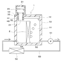
図2に示すように、本第2実施形態の電子機器2には配線2aが接続されている。配線2aは、電源や電気信号の伝送路として機能する。配線2aは、冷却槽10から接続部30および貯液槽20に延びるように設けられている。配線2aは、貯液槽20の大気開口部21から外部に取り出されている。
As shown in FIG. 2, wiring 2a is connected to the electronic device 2 of the second embodiment. The wiring 2a functions as a transmission path for power supply and electrical signals. Wiring 2 a is provided so as to extend from cooling tank 10 to connecting portion 30 and liquid storage tank 20 . The wiring 2a is taken out from the air opening 21 of the liquid storage tank 20 to the outside.
以上のように、本第2実施形態では、大気に開放した大気開口部21を利用して電子機器2の配線2aを外部に取り出している。このため、冷媒液11の外部流出を防ぐためのシール構造を設けることなく、電子機器2の配線2aを外部に取り出すことができる。
As described above, in the second embodiment, the wiring 2a of the electronic device 2 is taken out to the outside using the atmospheric opening 21 open to the atmosphere. Therefore, the wiring 2a of the electronic device 2 can be taken out to the outside without providing a sealing structure for preventing the refrigerant liquid 11 from flowing out to the outside.
(第3実施形態)
次に、本開示の第3実施形態について説明する。以下、上記各実施形態と異なる部分についてのみ説明する。 (Third Embodiment)
Next, a third embodiment of the present disclosure will be described. Only parts different from the above embodiments will be described below.
次に、本開示の第3実施形態について説明する。以下、上記各実施形態と異なる部分についてのみ説明する。 (Third Embodiment)
Next, a third embodiment of the present disclosure will be described. Only parts different from the above embodiments will be described below.
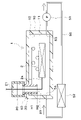
図3に示すように、本第3実施形態では、接続部30の冷却槽側開口部31が電子機器2よりも重力方向の上側に位置している。つまり、接続部30の冷却槽側開口部31の重力方向高さH2が電子機器2の重力方向高さH3よりも高くなっている。電子機器2の重力方向高さH3は、電子機器2の上端部の高さである。
As shown in FIG. 3, in the third embodiment, the cooling bath side opening 31 of the connecting portion 30 is positioned above the electronic device 2 in the gravitational direction. That is, the height H2 in the direction of gravity of the opening 31 of the connecting portion 30 on the side of the cooling bath is higher than the height H3 in the direction of gravity of the electronic device 2 . The gravity direction height H3 of the electronic device 2 is the height of the upper end portion of the electronic device 2 .
以上の本第3実施形態によれば、気体部12の体積が増大しても、冷媒液11の液面は接続部30の冷却槽側開口部31までしか下降しない。このため、冷媒液11の液面は、常に電子機器2よりも高い位置に維持される。これにより、電子機器2が冷媒液11から露出することなく、常に電子機器2を冷媒液11に浸漬させることができ、冷却装置1の冷却能力を維持することができる。また、気体部12が冷却槽側開口部31まで到達した場合は、気体部12の余分な気体が冷却槽側開口部31を介して貯液槽20の大気開口部21から外部に放出される。
According to the third embodiment described above, even if the volume of the gas portion 12 increases, the liquid level of the refrigerant liquid 11 only drops to the cooling tank side opening 31 of the connecting portion 30 . Therefore, the liquid level of the refrigerant liquid 11 is always maintained at a position higher than that of the electronic device 2 . As a result, the electronic device 2 can always be immersed in the coolant liquid 11 without being exposed from the coolant liquid 11, and the cooling capacity of the cooling device 1 can be maintained. Further, when the gas portion 12 reaches the cooling tank side opening 31, excess gas in the gas portion 12 is discharged to the outside from the atmosphere opening 21 of the liquid storage tank 20 through the cooling tank side opening 31. .
(第4実施形態)
次に、本開示の第4実施形態について説明する。以下、上記各実施形態と異なる部分についてのみ説明する。 (Fourth embodiment)
Next, a fourth embodiment of the present disclosure will be described. Only parts different from the above embodiments will be described below.
次に、本開示の第4実施形態について説明する。以下、上記各実施形態と異なる部分についてのみ説明する。 (Fourth embodiment)
Next, a fourth embodiment of the present disclosure will be described. Only parts different from the above embodiments will be described below.
図4に示すように、本第4実施形態の冷却槽10には、伝熱部13が設けられている。伝熱部13は、冷却槽10の内部で冷媒液11と気体部12に跨るように配置されており、冷媒液11と気体部12との間の伝熱を促進する。伝熱部13は、冷却槽10の上面における内壁側に固定されている。図4に示す例では、3つの伝熱部13が設けられているが、伝熱部13の数は任意に設定でき、1つ以上設けられていればよい。
As shown in FIG. 4, a heat transfer section 13 is provided in the cooling bath 10 of the fourth embodiment. The heat transfer part 13 is arranged so as to straddle the refrigerant liquid 11 and the gas part 12 inside the cooling tank 10 , and promotes heat transfer between the refrigerant liquid 11 and the gas part 12 . The heat transfer section 13 is fixed to the inner wall side of the upper surface of the cooling bath 10 . Although three heat transfer sections 13 are provided in the example shown in FIG. 4, the number of heat transfer sections 13 can be set arbitrarily, and one or more heat transfer sections 13 may be provided.
伝熱部13として、熱伝達率に優れた材料を用いている。伝熱部13として、例えばアルミニウムや銅からなる金属板を用いることができる。
A material with excellent heat transfer coefficient is used as the heat transfer part 13 . A metal plate made of aluminum or copper, for example, can be used as the heat transfer portion 13 .
以上の本第4実施形態によれば、気体部12は伝熱部13を介して冷媒液11によって冷却される。これにより、気体部12に含まれる気相冷媒の凝縮を促進することができ、気体部12の体積が増大することを抑制できる。この結果、冷却槽10における冷媒液11の液面が下降することを抑制でき、貯液槽20における冷媒液11の液面が上昇することを抑制できる。
According to the fourth embodiment described above, the gas portion 12 is cooled by the refrigerant liquid 11 via the heat transfer portion 13 . Thereby, the condensation of the gas-phase refrigerant contained in the gas portion 12 can be promoted, and an increase in the volume of the gas portion 12 can be suppressed. As a result, it is possible to suppress the liquid level of the refrigerant liquid 11 in the cooling tank 10 from falling, and to suppress the liquid level of the refrigerant liquid 11 in the liquid storage tank 20 from rising.
(第5実施形態)
次に、本開示の第5実施形態について説明する。以下、上記各実施形態と異なる部分についてのみ説明する。 (Fifth embodiment)
Next, a fifth embodiment of the present disclosure will be described. Only parts different from the above embodiments will be described below.
次に、本開示の第5実施形態について説明する。以下、上記各実施形態と異なる部分についてのみ説明する。 (Fifth embodiment)
Next, a fifth embodiment of the present disclosure will be described. Only parts different from the above embodiments will be described below.
図5に示すように、本第5実施形態では、冷却槽10の内部において、板状の電子機器2が水平に配置されている。つまり、冷却槽10の内部において、板状の電子機器2の板面が重力方向に交わるように配置されている。
As shown in FIG. 5, in the fifth embodiment, the plate-like electronic device 2 is arranged horizontally inside the cooling bath 10 . That is, inside the cooling bath 10, the plate surface of the plate-shaped electronic device 2 is arranged so as to intersect with the direction of gravity.
本第5実施形態の構成においても、冷却槽10と貯液槽20と接続部30で接続し、接続部30の冷却槽側開口部31の重力方向高さH2が冷却槽10の冷媒液11の液面高さH1よりも低くなっている。これにより、上記第1実施形態と同様、気相冷媒が接続部30を介して貯液槽20の大気開口部21から外部に流出することを抑制できる。
Also in the configuration of the fifth embodiment, the cooling tank 10 and the liquid storage tank 20 are connected by the connecting portion 30, and the height H2 in the gravity direction of the cooling tank side opening 31 of the connecting portion 30 is the refrigerant liquid 11 of the cooling tank 10. is lower than the liquid level height H1 of . As a result, as in the first embodiment, it is possible to prevent the gas-phase refrigerant from flowing out of the atmosphere opening 21 of the liquid storage tank 20 via the connecting portion 30 .
(第6実施形態)
次に、本開示の第6実施形態について説明する。以下、上記各実施形態と異なる部分についてのみ説明する。 (Sixth embodiment)
Next, a sixth embodiment of the present disclosure will be described. Only parts different from the above embodiments will be described below.
次に、本開示の第6実施形態について説明する。以下、上記各実施形態と異なる部分についてのみ説明する。 (Sixth embodiment)
Next, a sixth embodiment of the present disclosure will be described. Only parts different from the above embodiments will be described below.
図6に示すように、本第6実施形態では、貯液槽20が冷却槽10の側面に対向して設けられている。本第6実施形態の接続部30は冷却槽10の側面を貫通するように設けられており、冷却槽側開口部31は水平方向に開口している。貯液槽20の冷媒液11の液面は、冷却槽10の冷媒液11の液面よりも高くなっている。冷却槽10の側面と貯液槽20の間には隙間が設けられており、この隙間が断熱部40となっている。
As shown in FIG. 6, in the sixth embodiment, the liquid storage tank 20 is provided facing the side surface of the cooling tank 10 . The connection part 30 of the sixth embodiment is provided so as to penetrate the side surface of the cooling tank 10, and the cooling tank side opening 31 is opened in the horizontal direction. The liquid level of the refrigerant liquid 11 in the liquid storage tank 20 is higher than the liquid level of the refrigerant liquid 11 in the cooling tank 10 . A gap is provided between the side surface of the cooling tank 10 and the liquid storage tank 20 , and this gap serves as a heat insulating portion 40 .
本第6実施形態の構成においても、冷却槽10と貯液槽20と接続部30で接続し、接続部30の冷却槽側開口部31の重力方向高さH2が冷却槽10の冷媒液11の液面高さH1よりも低くなっている。これにより、上記第1実施形態と同様、気相冷媒が接続部30を介して貯液槽20の大気開口部21から外部に流出することを抑制できる。
Also in the configuration of the sixth embodiment, the cooling tank 10 and the liquid storage tank 20 are connected by the connecting portion 30, and the height H2 in the gravity direction of the cooling tank side opening 31 of the connecting portion 30 is the refrigerant liquid 11 of the cooling tank 10. is lower than the liquid level height H1 of . As a result, as in the first embodiment, it is possible to prevent the gas-phase refrigerant from flowing out of the atmosphere opening 21 of the liquid storage tank 20 via the connecting portion 30 .
また、本第6実施形態では、接続部30の冷却槽側開口部31は水平方向に開口しており、冷却槽側開口部31が重力方向下方に向かって開口している場合よりも、気相冷媒からなる気泡が冷却槽側開口部31に流入しにくくなっている。これにより、冷却槽10の内部で発生した気相冷媒が冷却槽側開口部31を介して貯液槽20の大気開口部21から外部に流出することを抑制でき、冷媒液11の減少を抑制できる。
In addition, in the sixth embodiment, the cooling tank side opening 31 of the connection part 30 is opened in the horizontal direction, and the cooling tank side opening 31 is open downward in the direction of gravity. It is difficult for air bubbles composed of the phase refrigerant to flow into the cooling tank side opening 31 . As a result, the vapor-phase refrigerant generated inside the cooling tank 10 can be suppressed from flowing out of the atmosphere opening 21 of the liquid storage tank 20 through the cooling tank side opening 31, and the decrease in the refrigerant liquid 11 can be suppressed. can.
本開示は上述の実施形態に限定されることなく、本開示の趣旨を逸脱しない範囲内で、以下のように種々変形可能である。また、上記各実施形態に開示された手段は、実施可能な範囲で適宜組み合わせてもよい。
The present disclosure is not limited to the above-described embodiments, and can be variously modified as follows without departing from the scope of the present disclosure. Moreover, the means disclosed in each of the above embodiments may be appropriately combined within the practicable range.
例えば、上記各実施形態では、冷却槽10で電子機器2を冷媒液11に浸漬して冷却するように構成したが、電子機器2以外の発熱体を冷媒液11に浸漬して冷却するようにしてもよい。冷却対象となる発熱体は、発熱し、かつ、冷媒液11に浸漬して冷却可能な物体であればよい。
For example, in each of the above-described embodiments, the electronic device 2 is immersed in the refrigerant liquid 11 in the cooling tank 10 to be cooled. may The heating element to be cooled may be any object that generates heat and can be cooled by being immersed in the refrigerant liquid 11 .
また、上記各実施形態の構成において、貯液槽20における冷媒液11の上面に蒸発防止剤を設けてもよい。貯液槽20における冷媒液11の上面は、大気との接触面である。蒸発防止剤は、冷媒液11の蒸発を抑制できればよく、例えば貯液槽20における冷媒液11の上面を覆う油膜用オイルや、貯液槽20における冷媒液11の上面を覆う粒子などを用いることができる。
In addition, in the configuration of each embodiment described above, an evaporation inhibitor may be provided on the upper surface of the refrigerant liquid 11 in the liquid storage tank 20 . The upper surface of the refrigerant liquid 11 in the liquid storage tank 20 is the contact surface with the atmosphere. The anti-evaporation agent is sufficient as long as it can suppress the evaporation of the refrigerant liquid 11. For example, oil for an oil film covering the upper surface of the refrigerant liquid 11 in the liquid storage tank 20, particles covering the upper surface of the refrigerant liquid 11 in the liquid storage tank 20, or the like can be used. can be done.
また、上記第4実施形態では、冷媒液11と気体部12との間の伝熱を促進する伝熱部13を設けたが、伝熱部13を異なる構成としてもよい。例えば、伝熱部13を大気と気体部12に跨るように設け、伝熱部13によって大気と気体部12との間の伝熱を促進して、気体部12を冷却するようにしてもよい。この場合、伝熱部13を冷却槽10の外部に露出させ、伝熱部13を冷却槽10の外部と内部に跨るように設ければよい。
Further, in the fourth embodiment, the heat transfer section 13 is provided to promote heat transfer between the refrigerant liquid 11 and the gas section 12, but the heat transfer section 13 may have a different configuration. For example, the heat transfer section 13 may be provided so as to straddle the atmosphere and the gas section 12 , and the heat transfer section 13 may promote heat transfer between the atmosphere and the gas section 12 to cool the gas section 12 . . In this case, the heat transfer section 13 may be exposed to the outside of the cooling tank 10 , and the heat transfer section 13 may be provided so as to straddle the outside and the inside of the cooling tank 10 .
また、接続部30の冷却槽側開口部31を上記第1~第5実施形態では重力方向下方に開口させ、上記第6実施形態では水平方向に開口させるようにしたが、冷却槽側開口部31を重力方向上方に向かって開口させてもよい。これにより、気相冷媒からなる気泡が冷却槽側開口部31に流入しにくくなり、気相冷媒が冷却槽側開口部31を介して貯液槽20の大気開口部21から外部に流出することを抑制でき、冷媒液11の減少を抑制できる。
Further, the cooling tank side opening 31 of the connection part 30 is opened downward in the direction of gravity in the first to fifth embodiments, and is opened horizontally in the sixth embodiment. 31 may be opened upward in the direction of gravity. As a result, air bubbles made of the gaseous refrigerant are less likely to flow into the cooling tank side opening 31, and the gaseous refrigerant is prevented from flowing out of the atmosphere opening 21 of the liquid storage tank 20 through the cooling tank side opening 31. can be suppressed, and the decrease in the refrigerant liquid 11 can be suppressed.
また、上記各実施形態では、冷却槽10と貯液槽20との間に隙間を設けることで、空気層からなる断熱部40を構成したが、冷却槽10と貯液槽20との間に断熱部材を設けることで、断熱部40を構成してもよい。
Further, in each of the above-described embodiments, a gap is provided between the cooling tank 10 and the liquid storage tank 20 to form the heat insulation part 40 composed of an air layer. The heat insulating part 40 may be configured by providing a heat insulating member.
本開示は、実施例に準拠して記述されたが、本開示は当該実施例や構造に限定されるものではないと理解される。本開示は、様々な変形例や均等範囲内の変形をも包含する。加えて、様々な組み合わせや形態が本開示に示されているが、それらに一要素のみ、それ以上、あるいはそれ以下、を含む他の組み合わせや形態をも、本開示の範疇や思想範囲に入るものである。
Although the present disclosure has been described with reference to examples, it is understood that the present disclosure is not limited to those examples or structures. The present disclosure also includes various modifications and modifications within the equivalent range. In addition, while various combinations and configurations are shown in this disclosure, other combinations and configurations, including single elements, more, or less, are within the scope and spirit of this disclosure. It is.
Claims (6)
- 発熱体(2)を浸漬して冷却するための冷媒液(11)を貯蔵する冷却槽(10)と、
前記冷却槽の外部で前記冷媒液を貯蔵するとともに、大気に開放する大気開口部(21)を有する貯液槽(20)と、
前記貯液槽と前記冷却槽とを接続し、前記冷媒液が通過可能となっている接続部(30)と、
を備え、
前記接続部のうち前記冷却槽側に形成された冷却槽側開口部(31)は、重力方向において、前記冷却槽内で前記冷媒液の液面の下側又は同じ高さに位置しており、
前記冷却槽内で発生した気体は前記冷却槽内の上部で貯留されて気体部(12)を形成し、
前記気体部の体積変動に応じて、前記接続部を介して前記冷却槽と前記貯液槽との間を前記冷媒液が流動する冷却装置。 a cooling tank (10) for storing a refrigerant liquid (11) for submerging and cooling the heating element (2);
a liquid storage tank (20) for storing the refrigerant liquid outside the cooling tank and having an atmospheric opening (21) open to the atmosphere;
a connecting portion (30) connecting the liquid storage tank and the cooling tank and through which the refrigerant liquid can pass;
with
The cooling tank side opening (31) formed on the cooling tank side of the connection part is positioned below or at the same height as the liquid surface of the refrigerant liquid in the cooling tank in the gravitational direction. ,
The gas generated in the cooling tank is stored in the upper part of the cooling tank to form a gas part (12),
A cooling device in which the refrigerant liquid flows between the cooling tank and the liquid storage tank via the connecting part according to the volume change of the gas part. - 前記発熱体の発熱により、前記冷却槽内の前記冷媒液が沸騰可能となっている請求項1に記載の冷却装置。 The cooling device according to claim 1, wherein the refrigerant liquid in the cooling tank can boil due to the heat generated by the heating element.
- 前記冷却槽の前記冷媒液を冷却する熱交換器(52)と、
前記冷却槽の前記冷媒液を前記熱交換器に循環させる循環回路(50)と、
を備える請求項1または2に記載の冷却装置。 a heat exchanger (52) for cooling the refrigerant liquid in the cooling tank;
a circulation circuit (50) for circulating the refrigerant liquid in the cooling tank to the heat exchanger;
3. A cooling device according to claim 1 or 2, comprising: - 前記発熱体は電子機器であり、前記電子機器の配線(2a)は前記大気開口部から外部に取り出されている請求項1ないし3のいずれか1つに記載の冷却装置。 The cooling device according to any one of claims 1 to 3, wherein the heating element is an electronic device, and the wiring (2a) of the electronic device is taken out from the atmosphere opening.
- 前記冷却槽側開口部は、重力方向において、前記冷却槽内における前記発熱体よりも上側に位置している請求項1ないし4のいずれか1つに記載の冷却装置。 The cooling device according to any one of claims 1 to 4, wherein the cooling-tank-side opening is located above the heating element in the cooling tank in the direction of gravity.
- 前記冷却槽内で前記冷媒液と前記気体部に跨るように設けられ、前記冷媒液と前記気体部との熱交換を促進する伝熱部(13)を備えている請求項1ないし5のいずれか1つに記載の冷却装置。 6. The cooling tank according to any one of claims 1 to 5, further comprising a heat transfer part (13) provided so as to straddle the refrigerant liquid and the gas part in the cooling tank and promoting heat exchange between the refrigerant liquid and the gas part. 1. A cooling device according to claim 1.
Priority Applications (2)
| Application Number | Priority Date | Filing Date | Title |
|---|---|---|---|
| CN202280018954.8A CN116918469A (en) | 2021-03-10 | 2022-02-11 | cooling device |
| US18/461,375 US20230413482A1 (en) | 2021-03-10 | 2023-09-05 | Cooling device |
Applications Claiming Priority (2)
| Application Number | Priority Date | Filing Date | Title |
|---|---|---|---|
| JP2021037980A JP2022138221A (en) | 2021-03-10 | 2021-03-10 | Cooling device |
| JP2021-037980 | 2021-03-10 |
Related Child Applications (1)
| Application Number | Title | Priority Date | Filing Date |
|---|---|---|---|
| US18/461,375 Continuation US20230413482A1 (en) | 2021-03-10 | 2023-09-05 | Cooling device |
Publications (1)
| Publication Number | Publication Date |
|---|---|
| WO2022190766A1 true WO2022190766A1 (en) | 2022-09-15 |
Family
ID=83227586
Family Applications (1)
| Application Number | Title | Priority Date | Filing Date |
|---|---|---|---|
| PCT/JP2022/005522 WO2022190766A1 (en) | 2021-03-10 | 2022-02-11 | Cooling device |
Country Status (4)
| Country | Link |
|---|---|
| US (1) | US20230413482A1 (en) |
| JP (1) | JP2022138221A (en) |
| CN (1) | CN116918469A (en) |
| WO (1) | WO2022190766A1 (en) |
Families Citing this family (1)
| Publication number | Priority date | Publication date | Assignee | Title |
|---|---|---|---|---|
| US20230164952A1 (en) * | 2021-11-24 | 2023-05-25 | Microsoft Technology Licensing, Llc | Systems and methods for recovering fluid in immersion-cooled datacenters |
Citations (5)
| Publication number | Priority date | Publication date | Assignee | Title |
|---|---|---|---|---|
| US20130105120A1 (en) * | 2011-10-26 | 2013-05-02 | International Business Machines Corporation | Multi-fluid, two-phase immersion-cooling of electronic component(s) |
| JP2017150715A (en) * | 2016-02-24 | 2017-08-31 | 富士通株式会社 | Cooling device and electronic device |
| US20170295670A1 (en) * | 2016-04-07 | 2017-10-12 | Hamilton Sundstrand Corporation | Immersion cooled electronic assemblies |
| WO2018020582A1 (en) * | 2016-07-26 | 2018-02-01 | 富士通株式会社 | Cooling device and electronic device |
| JP2019016764A (en) * | 2017-07-05 | 2019-01-31 | 富士通株式会社 | Liquid immersion cooling device and information processing device |
-
2021
- 2021-03-10 JP JP2021037980A patent/JP2022138221A/en active Pending
-
2022
- 2022-02-11 CN CN202280018954.8A patent/CN116918469A/en active Pending
- 2022-02-11 WO PCT/JP2022/005522 patent/WO2022190766A1/en active Application Filing
-
2023
- 2023-09-05 US US18/461,375 patent/US20230413482A1/en active Pending
Patent Citations (5)
| Publication number | Priority date | Publication date | Assignee | Title |
|---|---|---|---|---|
| US20130105120A1 (en) * | 2011-10-26 | 2013-05-02 | International Business Machines Corporation | Multi-fluid, two-phase immersion-cooling of electronic component(s) |
| JP2017150715A (en) * | 2016-02-24 | 2017-08-31 | 富士通株式会社 | Cooling device and electronic device |
| US20170295670A1 (en) * | 2016-04-07 | 2017-10-12 | Hamilton Sundstrand Corporation | Immersion cooled electronic assemblies |
| WO2018020582A1 (en) * | 2016-07-26 | 2018-02-01 | 富士通株式会社 | Cooling device and electronic device |
| JP2019016764A (en) * | 2017-07-05 | 2019-01-31 | 富士通株式会社 | Liquid immersion cooling device and information processing device |
Also Published As
| Publication number | Publication date |
|---|---|
| US20230413482A1 (en) | 2023-12-21 |
| CN116918469A (en) | 2023-10-20 |
| JP2022138221A (en) | 2022-09-26 |
Similar Documents
| Publication | Publication Date | Title |
|---|---|---|
| JP6015675B2 (en) | COOLING DEVICE AND ELECTRONIC DEVICE USING THE SAME | |
| US9297589B2 (en) | Boiling heat transfer device | |
| US7327572B2 (en) | Heat dissipating device with enhanced boiling/condensation structure | |
| WO2011145618A1 (en) | Ebullient cooling device | |
| JP6137167B2 (en) | Cooling device and cooling system | |
| JP2018088433A (en) | Cooling system and cooling method for electronic equipment | |
| WO2013018667A1 (en) | Cooling device and electronic device using same | |
| US20230413482A1 (en) | Cooling device | |
| JP6285356B2 (en) | Boiling cooler | |
| JP6536406B2 (en) | Electronic device housing apparatus and electronic device cooling system | |
| JP2010079401A (en) | Cooling system and electronic equipment using the same | |
| JP2014074568A (en) | Loop type thermo-siphon and electronic apparatus | |
| JP2018133529A (en) | Cooling device | |
| JP2011247506A (en) | Cooling system for data center | |
| WO2022190868A1 (en) | Cooling device | |
| WO2020255883A1 (en) | Cooling device | |
| JP5860728B2 (en) | Electronic equipment cooling system | |
| WO2023157717A1 (en) | Cooling device | |
| JP2023149859A (en) | Cooling device | |
| WO2024014024A1 (en) | Cooling device | |
| JP7168850B2 (en) | Evaporator and cooling system | |
| JP2023135867A (en) | Cooler | |
| WO2023139989A1 (en) | Cooling device | |
| WO2013073696A1 (en) | Cooling device and electronic device using same | |
| JP2004349652A (en) | Boiling cooler |
Legal Events
| Date | Code | Title | Description |
|---|---|---|---|
| 121 | Ep: the epo has been informed by wipo that ep was designated in this application |
Ref document number: 22766731 Country of ref document: EP Kind code of ref document: A1 |
|
| WWE | Wipo information: entry into national phase |
Ref document number: 202280018954.8 Country of ref document: CN |
|
| NENP | Non-entry into the national phase |
Ref country code: DE |
|
| 122 | Ep: pct application non-entry in european phase |
Ref document number: 22766731 Country of ref document: EP Kind code of ref document: A1 |