【0001】
【発明の属する技術分野】
本発明は、冷媒の沸騰と凝縮による潜熱移動によって半導体素子等の発熱体を冷却する沸騰冷却装置に関するものである。
【0002】
【従来の技術】
従来の沸騰冷却装置として、例えば特許文献1に示されるものが知られている。即ち、図4に示すように、沸騰冷却装置100は、内部に冷媒を貯留する冷媒槽110と、この冷媒槽110に組付けられる放熱部120とで構成され、冷媒槽110の一壁面を形成する受熱面111に発熱体(半導体素子等)10が取付けられる。
【0003】
放熱部120は、冷媒槽110の受熱面111と対向する放熱面112に対し略直立して組付けられる一組のヘッダ121間を連通する複数本の放熱チューブ122と、放熱面積を増大するための放熱フィン123とから構成される。
【0004】
そして、冷媒槽110内に貯留された冷媒は、発熱体10の熱を受けて沸騰気化し、上昇して冷媒槽110から一方のヘッダ121を通って放熱チューブ122内へ流れ込み、放熱チューブ122内を流れる際に、例えば図中の下側から供給される冷却風を受けて外気に放熱して凝縮し、凝縮液となって他方のヘッダ121から冷媒槽110に還流する。これにより、発熱体10から発生した熱が冷媒に伝達されて放熱部120で外気に放出されることで発熱体10が冷却される。
【0005】
尚、ここでは冷媒槽110へのヘッダ121の差込量が規制されるようにしており、冷媒槽110側の放熱フィン123の潰れや浮きを防止して、放熱性能の低下を防ぐようにしている。
【0006】
【特許文献1】
特開2000−236055号公報
【0007】
【発明が解決しようとする課題】
しかしながら、近年、上記のような沸騰冷却装置100においては、発熱体10の実装密度の向上や各種電子機器への共通使用のために、発熱体10を放熱面112側にも取付け、また冷媒槽110は図4に示す垂直方向姿勢に対して水平方向姿勢での使用も可能となるような要求も出ている。
【0008】
このような要求に対して、まず図5に示すように、冷媒槽110を垂直方向姿勢として2つの発熱体10、11を受熱面111および放熱面112に取付けした場合、冷媒槽110内に封入される冷媒は、放熱部120に掛からず、且つ両発熱体10、11領域の冷媒槽110内壁に接触するように封入されることになる。これによって冷媒は両発熱体10、11の熱によって沸騰され、沸騰気化した冷媒は放熱部120に流入し(図中の実線)、凝縮時の凝縮潜熱を外気に放出することで両発熱体10、11の冷却を可能とする(凝縮後の冷媒流れを図中の破線で示す)。
【0009】
一方、冷媒槽110を図6に示すように水平方向姿勢にして配置すると、冷媒は冷媒槽110内全体に広がり、受熱面112側の発熱体11領域の冷媒槽110内壁には冷媒が接触しない状態となるので、この発熱体11の冷却ができなくなる。
【0010】
そこで、図7に示すように、冷媒槽110を水平方向姿勢として、発熱体11側の冷媒槽110内壁にも冷媒が接触するようにしてやれば、発熱体11の冷却が可能となるが、図8に示すように、冷媒槽110を垂直方向姿勢にすると、放熱部120に冷媒が流入し、凝縮面積が減少して冷却性能が低下してしまう。
【0011】
本発明の目的は、上記問題に鑑み、発熱体の設置位置および冷媒槽の配置姿勢にかかわらず発熱体の冷却を可能とする沸騰冷却装置を提供することにある。
【0012】
【課題を解決するための手段】
本発明は上記目的を達成するために、以下の技術的手段を採用する。
【0013】
請求項1に記載の発明では、対向する2つの外表面(111、112)の少なくとも一方に発熱体(10、11)が取付けられ、内部に冷媒を貯留する冷媒槽(110)と、2つの外表面(111、112)の一方に設けられ、発熱体(10、11)によって沸騰気化した冷媒を凝縮液化して、冷媒槽(110)に戻す放熱部(120)とを備える沸騰冷却装置において、冷媒槽(110)には、冷媒槽(110)の配置姿勢を変えた場合にも、冷媒が発熱体(10、11)の取付けられる領域近傍の冷媒槽(110)内壁に接触しつつ、放熱部(120)に流入しないように冷媒の水位を調整する水位調整部(113)が設けられたことを特徴としている。
【0014】
これにより、冷媒槽(110)の配置姿勢を変えた場合でも、放熱部(120)での凝縮面積を減少すること無く、発熱体(10、11)の熱を確実に冷媒に伝達して発熱体(10、11)の冷却が可能となる。
【0015】
上記水位調整部(113)としては、請求項2に記載の発明のように、2つの外表面(111、112)が垂直方向を向く際に、放熱部(120)よりも下側に位置し、放熱部(120)と同じ側に膨出するタンク部(113)として形成すれば良い。
【0016】
尚、上記各手段の括弧内の符号は、後述する実施形態記載の具体的手段との対応関係を示すものである。
【0017】
【発明の実施の形態】
(第1実施形態)
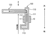
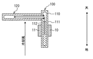
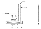
本発明の沸騰冷却装置100における第1実施形態を図1〜図3に示す。図1は、後述する冷媒槽110を垂直方向姿勢とした場合の沸騰冷却装置100を示す断面図、図2は、図1におけるA方向から見た沸騰冷却装置100を示す矢視図、図3は、冷媒槽110を水平方向姿勢とした場合の沸騰冷却装置100を示す断面図である。
【0018】
沸騰冷却装置100は、別々に設けられる半導体素子等の発熱体10、11を冷却するようにしたもので、冷媒槽110と放熱部120とから構成されている。そして、以下説明する各部材は、アルミニウムあるいはアルミニウム合金より成り、各部材間で接合される部位に施されたろう材により一体でろう付けされている。
【0019】
まず、冷媒槽110は、扁平箱状をベースとする冷媒容器であり、外表面としての受熱面111と放熱面112とが対向するように設けられている。そして、この受熱面111および放熱面112の略中央には発熱体10、11が図示しないボルト等の締め付けによりそれぞれ固定されている。ここで、発熱体10、11と受熱面111、放熱面112との間の接触熱抵抗を小さくするために、両者間に熱伝導グリースを介在させても良い。
【0020】
放熱部120は、2本のヘッダ121を連通する複数本の放熱チューブ122と、各放熱チューブ122間に介在される放熱フィン123とから構成される。2本のヘッダ121は、それぞれ冷媒槽110の一端側(図1中の上側)で放熱面112から略直立して組付けられ、冷媒槽110の内部空間と連通して設けられている。放熱チューブ122は、放熱面112および放熱面112の端部(図1中の上下方向の端部)と略平行に(あるいは放熱面112の端部に対して若干傾斜して)配列され、2本のヘッダ121を介して冷媒槽110の内部空間と連通している。放熱フィン123は、周知のコルゲートフィンであり、放熱面積を増大させるために使用される。
【0021】
そして、本発明の特徴部として冷媒槽110には、水位調整部としてのタンク部113を設けるようにしている。タンク部113は、冷媒槽110の他端側(反放熱部側であり、図1中では放熱部120の下側)で放熱面112から放熱部120(ヘッダ121)と同じ側に膨出するようにしている。タンク部113の内部空間の容積は、冷媒槽110における発熱体10、11と放熱部120との間から一端側(図1中の上側)までの容積と略同等となるようにしている。
【0022】
そして、冷媒槽110の内部空間には所定量の冷媒が封入されている。冷媒は、水、アルコール、フロロカーボン、フロン等が用いられる。ここで冷媒の水位は、図1に示すように、放熱部120を上側にして受熱面111および放熱面112を垂直方向に向けた時に、発熱体10、11と放熱部120との間になるようにしている。また、図3に示すように、放熱部120が上を向くようにして受熱面111および放熱面112を水平方向に向けた時には、タンク部113を除く冷媒槽110内が冷媒によって満たされるようにしている。即ち、冷媒槽110の配置姿勢を変えた場合でも、タンク部113によって冷媒は、発熱体10、11の取付けられる領域近傍の冷媒槽110の内壁に接触しつつ、放熱部120(ヘッダ121、放熱チューブ122)には流入しないようにしている。
【0023】
次に、上記構成に基づく沸騰冷却装置100の作動および作用効果について説明する。
【0024】
まず、放熱部120を上側にして冷媒槽110の受熱面111、放熱面112を垂直方向にして用いた場合(図1)、冷媒槽110に貯留されている冷媒は、発熱体10、11から受熱して沸騰気化し、冷媒槽110内を上昇し、一方のヘッダ121内に流れ込み(図1中の実線)、そのヘッダ121から各放熱チューブ122に分散して流れる。放熱チューブ122内へ流入した冷媒蒸気は、この放熱チューブ122内を流れる際に、例えば図1中の下側に配置される送風手段から供給される冷却風を受けて冷却され、凝縮液となって他方のヘッダ121から冷媒槽110へと還流する(図1中の破線)。
【0025】
このように、発熱体10、11から発生した熱が冷媒に伝達されて放熱部120へ輸送され、この放熱部120で冷媒蒸気が凝縮する際に凝縮潜熱として放出され、放熱フィン123を介して外気(冷却風)に放熱される。即ち、発熱体10、11から発生した熱が冷媒に伝達されて放熱部120で外気に放出されることで発熱体10、11が冷却される。
【0026】
一方、放熱部120が上を向くように冷媒槽110の受熱面111、放熱面112を水平方向にして用いた場合(図3)、タンク部113内の冷媒が冷媒槽110内を満たすように、且つ放熱部120に流入しないように水位が保たれる。そして、上記と同様に発熱体10、11から発生した熱が冷媒に伝達されて放熱部120で外気に放出されることで発熱体10、11が冷却されることになる。
【0027】
これにより、冷媒槽110の配置姿勢を変えた場合(垂直方向姿勢あるいは水平方向姿勢にした場合)でも、放熱部120での凝縮面積を減少すること無く、発熱体10、11の熱を確実に冷媒に伝達して発熱体10、11の冷却が可能となる。
【0028】
(その他の実施形態)
上記第1実施形態では、発熱体10、11を冷媒槽110に2つ設けるものとして説明したが、これに限らず、少なくともいずれか一方に設けるものとしても良い。
【図面の簡単な説明】
【図1】第1実施形態における沸騰冷却装置の冷媒槽を垂直方向姿勢で用いる場合を示す断面図である。
【図2】図1におけるA方向からの沸騰冷却装置を示す矢視図である。
【図3】第1実施形態における沸騰冷却装置の冷媒槽を水平方向姿勢で用いる場合を示す断面図である。
【図4】従来技術の沸騰冷却装置を示す斜視図である。
【図5】従来技術の沸騰冷却装置に2つの発熱体を設け、垂直方向姿勢として用いる場合を示す断面図である。
【図6】図5に対して水平方向姿勢とした場合を示す断面図である。
【図7】従来技術の沸騰冷却装置に2つの発熱体を設け、水平方向姿勢として用いる場合を示す断面図である。
【図8】図7に対して垂直方向姿勢とした場合を示す断面図である。
【符号の説明】
10、11 発熱体
100 沸騰冷却装置
110 冷媒槽
111 受熱面(外表面)
112 放熱面(外表面)
113 タンク部(水位調整部)
120 放熱部[0001]
TECHNICAL FIELD OF THE INVENTION
The present invention relates to a boiling cooling device that cools a heating element such as a semiconductor element by latent heat transfer due to boiling and condensation of a refrigerant.
[0002]
[Prior art]
BACKGROUND ART As a conventional boiling cooling device, for example, a device disclosed in Patent Document 1 is known. That is, as shown in FIG. 4, the boiling cooling device 100 includes a refrigerant tank 110 for storing a refrigerant therein and a radiator 120 attached to the refrigerant tank 110 to form one wall surface of the refrigerant tank 110. The heating element (semiconductor element or the like) 10 is attached to the heat receiving surface 111.
[0003]
The heat dissipating part 120 is provided with a plurality of heat dissipating tubes 122 communicating between a pair of headers 121 mounted substantially upright with respect to the heat dissipating surface 112 facing the heat receiving surface 111 of the refrigerant tank 110, and for increasing a heat dissipating area. And the heat radiation fins 123.
[0004]
The refrigerant stored in the refrigerant tank 110 receives heat from the heating element 10, boils and evaporates, rises and flows from the refrigerant tank 110 through one header 121 into the heat radiation tube 122, and For example, when cooling air supplied from the lower side in the drawing is received, heat is radiated to the outside air and condensed, and condensed liquid is returned from the other header 121 to the refrigerant tank 110. Thereby, the heat generated from the heating element 10 is transmitted to the refrigerant and released to the outside air by the heat radiating section 120, so that the heating element 10 is cooled.
[0005]
Here, the insertion amount of the header 121 into the refrigerant tank 110 is regulated, so that the radiating fins 123 on the refrigerant tank 110 side are prevented from being crushed or floated, and the heat radiation performance is prevented from lowering. I have.
[0006]
[Patent Document 1]
JP 2000-236055 A
[Problems to be solved by the invention]
However, in recent years, in the above-described boiling cooling device 100, the heating element 10 is also attached to the heat radiation surface 112 side in order to improve the mounting density of the heating element 10 and to be commonly used for various electronic devices. There is also a request 110 that can be used in a horizontal orientation as compared to the vertical orientation shown in FIG.
[0008]
In response to such a request, first, as shown in FIG. 5, when the two heating elements 10 and 11 are attached to the heat receiving surface 111 and the heat radiating surface 112 while the refrigerant tank 110 is in the vertical orientation, it is sealed in the refrigerant tank 110. The refrigerant is sealed so as not to be applied to the heat radiating portion 120 and to contact the inner wall of the refrigerant tank 110 in the area of the heating elements 10 and 11. As a result, the refrigerant is boiled by the heat of the heating elements 10 and 11, and the boiling vaporized refrigerant flows into the heat radiating section 120 (solid line in the figure), and discharges the latent heat of condensation at the time of condensation to the outside air, thereby releasing the heating elements 10. , 11 (the refrigerant flow after condensation is indicated by a broken line in the figure).
[0009]
On the other hand, when the refrigerant tank 110 is arranged in a horizontal posture as shown in FIG. 6, the refrigerant spreads throughout the refrigerant tank 110, and the refrigerant does not contact the inner wall of the refrigerant tank 110 in the area of the heating element 11 on the heat receiving surface 112 side. As a result, the heating element 11 cannot be cooled.
[0010]
Therefore, as shown in FIG. 7, if the refrigerant tank 110 is set in a horizontal posture so that the refrigerant contacts the inner wall of the refrigerant tank 110 on the side of the heating element 11, the heating element 11 can be cooled. As shown in FIG. 8, when the refrigerant tank 110 is in the vertical position, the refrigerant flows into the heat radiating portion 120, the condensing area decreases, and the cooling performance decreases.
[0011]
An object of the present invention, in view of the above problems, is to provide a boiling cooling device that enables cooling of a heating element regardless of the installation position of the heating element and the orientation of the coolant tank.
[0012]
[Means for Solving the Problems]
The present invention employs the following technical means to achieve the above object.
[0013]
According to the first aspect of the present invention, a heating element (10, 11) is attached to at least one of two opposing outer surfaces (111, 112), and a refrigerant tank (110) for storing a refrigerant therein, A cooling unit provided on one of the outer surfaces (111, 112) and condensing and liquefying the refrigerant vaporized by the heating elements (10, 11) to return to the refrigerant tank (110); In the refrigerant tank (110), even when the arrangement posture of the refrigerant tank (110) is changed, the refrigerant contacts the inner wall of the refrigerant tank (110) near the area where the heating element (10, 11) is attached. A water level adjusting section (113) for adjusting the water level of the refrigerant so as not to flow into the heat radiating section (120) is provided.
[0014]
Thereby, even when the arrangement posture of the refrigerant tank (110) is changed, the heat of the heating elements (10, 11) is reliably transmitted to the refrigerant without reducing the condensing area in the heat radiating section (120). The body (10, 11) can be cooled.
[0015]
The water level adjusting section (113) is located below the heat radiating section (120) when the two outer surfaces (111, 112) face the vertical direction as in the invention according to claim 2. It may be formed as a tank part (113) that swells on the same side as the heat radiating part (120).
[0016]
Note that the reference numerals in parentheses of the above means indicate the correspondence with specific means described in the embodiment described later.
[0017]
BEST MODE FOR CARRYING OUT THE INVENTION
(1st Embodiment)
1 to 3 show a first embodiment of a boiling cooling device 100 of the present invention. FIG. 1 is a cross-sectional view showing a boiling cooling device 100 when a later-described refrigerant tank 110 is in a vertical posture, FIG. 2 is an arrow view showing the boiling cooling device 100 viewed from a direction A in FIG. FIG. 3 is a cross-sectional view illustrating the boiling cooling device 100 when the refrigerant tank 110 is in a horizontal posture.
[0018]
The boiling cooling device 100 is configured to cool the heating elements 10 and 11 such as semiconductor elements provided separately, and includes a refrigerant tank 110 and a heat radiating section 120. Each member described below is made of aluminum or an aluminum alloy, and is integrally brazed by a brazing material applied to a portion to be joined between the members.
[0019]
First, the refrigerant tank 110 is a refrigerant container having a flat box shape as a base, and is provided such that a heat receiving surface 111 as an outer surface and a heat radiation surface 112 face each other. Heating elements 10 and 11 are fixed to substantially the center of the heat receiving surface 111 and the heat radiating surface 112 by tightening bolts (not shown). Here, in order to reduce the contact thermal resistance between the heating elements 10 and 11 and the heat receiving surface 111 and the heat radiating surface 112, a heat conductive grease may be interposed therebetween.
[0020]
The heat radiating section 120 includes a plurality of heat radiating tubes 122 communicating the two headers 121 and heat radiating fins 123 interposed between the heat radiating tubes 122. The two headers 121 are mounted substantially upright from the heat radiating surface 112 on one end side (upper side in FIG. 1) of the refrigerant tank 110, and are provided in communication with the internal space of the refrigerant tank 110. The heat radiating tubes 122 are arranged substantially parallel to the heat radiating surface 112 and the end of the heat radiating surface 112 (the end in the vertical direction in FIG. 1) (or slightly inclined with respect to the end of the heat radiating surface 112). It communicates with the internal space of the refrigerant tank 110 via the header 121 of the book. The heat radiation fins 123 are well-known corrugated fins, and are used to increase the heat radiation area.
[0021]
And, as a characteristic part of the present invention, the refrigerant tank 110 is provided with a tank part 113 as a water level adjusting part. The tank portion 113 bulges from the heat radiating surface 112 to the same side as the heat radiating portion 120 (header 121) at the other end side of the refrigerant tank 110 (on the side opposite to the heat radiating portion and below the heat radiating portion 120 in FIG. 1). Like that. The volume of the internal space of the tank unit 113 is set to be substantially equal to the volume from the space between the heating elements 10 and 11 and the heat radiation unit 120 in the refrigerant tank 110 to one end side (upper side in FIG. 1).
[0022]
A predetermined amount of refrigerant is sealed in the internal space of the refrigerant tank 110. As the refrigerant, water, alcohol, fluorocarbon, chlorofluorocarbon or the like is used. Here, as shown in FIG. 1, the water level of the refrigerant is between the heat generating elements 10 and 11 and the heat radiating part 120 when the heat receiving part 111 and the heat radiating face 112 are oriented vertically with the heat radiating part 120 facing upward. Like that. As shown in FIG. 3, when the heat receiving portion 111 and the heat releasing surface 112 are oriented horizontally with the heat radiating portion 120 facing upward, the inside of the refrigerant tank 110 excluding the tank portion 113 is filled with the refrigerant. ing. That is, even when the arrangement posture of the refrigerant tank 110 is changed, the refrigerant contacts the inner wall of the refrigerant tank 110 near the area where the heating elements 10 and 11 are attached, while the radiator 120 (the header 121, the radiator). It does not flow into the tube 122).
[0023]
Next, an operation and an effect of the boiling cooling device 100 based on the above configuration will be described.
[0024]
First, when the heat receiving portion 111 and the heat radiating surface 112 of the refrigerant tank 110 are used in a vertical direction with the heat radiating portion 120 being on the upper side (FIG. 1), the refrigerant stored in the refrigerant tank 110 is discharged from the heating elements 10 and 11. Upon receiving heat, it evaporates, rises in the refrigerant tank 110, flows into one header 121 (solid line in FIG. 1), and flows from the header 121 to each of the radiation tubes 122. The refrigerant vapor that has flowed into the heat radiating tube 122 is cooled by receiving cooling air supplied from, for example, a blowing unit disposed on the lower side in FIG. Then, the refrigerant flows from the other header 121 to the refrigerant tank 110 (broken line in FIG. 1).
[0025]
In this way, the heat generated from the heating elements 10 and 11 is transmitted to the refrigerant and transported to the heat radiating unit 120, and is released as condensation latent heat when the refrigerant vapor condenses in the heat radiating unit 120, and is discharged through the heat radiating fins 123. Heat is radiated to the outside air (cooling air). That is, the heat generated from the heating elements 10 and 11 is transmitted to the refrigerant and released to the outside air by the heat radiating unit 120, so that the heating elements 10 and 11 are cooled.
[0026]
On the other hand, when the heat receiving surface 111 and the heat radiating surface 112 of the refrigerant tank 110 are used in a horizontal direction so that the heat radiating portion 120 faces upward (FIG. 3), the refrigerant in the tank portion 113 fills the refrigerant tank 110. In addition, the water level is maintained so as not to flow into the heat radiating section 120. Then, similarly to the above, the heat generated from the heating elements 10 and 11 is transmitted to the refrigerant and released to the outside air by the radiator 120, so that the heating elements 10 and 11 are cooled.
[0027]
Thereby, even when the arrangement posture of the refrigerant tank 110 is changed (vertical posture or horizontal posture), the heat of the heating elements 10 and 11 is surely transferred without reducing the condensation area in the heat radiating part 120. By transmitting the heat to the refrigerant, the heating elements 10 and 11 can be cooled.
[0028]
(Other embodiments)
In the first embodiment, the description has been made assuming that the two heating elements 10 and 11 are provided in the refrigerant tank 110, but the present invention is not limited to this, and the heating elements may be provided in at least one of them.
[Brief description of the drawings]
FIG. 1 is a sectional view showing a case where a refrigerant tank of a boiling cooling device according to a first embodiment is used in a vertical posture.
FIG. 2 is a view in the direction of an arrow showing a boiling cooling device from a direction A in FIG. 1;
FIG. 3 is a cross-sectional view showing a case where a refrigerant tank of the boiling cooling device according to the first embodiment is used in a horizontal posture.
FIG. 4 is a perspective view showing a conventional boiling cooling device.
FIG. 5 is a cross-sectional view showing a case where two heating elements are provided in a conventional cooling apparatus and used in a vertical posture.
FIG. 6 is a cross-sectional view illustrating a case where the camera is set in a horizontal posture with respect to FIG.
FIG. 7 is a cross-sectional view showing a case in which two heating elements are provided in a conventional cooling device and used in a horizontal posture.
FIG. 8 is a cross-sectional view showing a case in which the attitude is set in a direction perpendicular to FIG.
[Explanation of symbols]
10, 11 Heating element 100 Boiling cooling device 110 Refrigerant tank 111 Heat receiving surface (outer surface)
112 Heat dissipation surface (outer surface)
113 Tank part (water level adjustment part)
120 radiator