WO2022190868A1 - Cooling device - Google Patents
Cooling device Download PDFInfo
- Publication number
- WO2022190868A1 WO2022190868A1 PCT/JP2022/007432 JP2022007432W WO2022190868A1 WO 2022190868 A1 WO2022190868 A1 WO 2022190868A1 JP 2022007432 W JP2022007432 W JP 2022007432W WO 2022190868 A1 WO2022190868 A1 WO 2022190868A1
- Authority
- WO
- WIPO (PCT)
- Prior art keywords
- refrigerant liquid
- heat transfer
- cooling
- gas
- cooling tank
- Prior art date
Links
- 238000001816 cooling Methods 0.000 title claims abstract description 209
- 239000003507 refrigerant Substances 0.000 claims abstract description 217
- 238000009835 boiling Methods 0.000 claims abstract description 16
- 238000010438 heat treatment Methods 0.000 claims abstract description 11
- 238000009833 condensation Methods 0.000 claims abstract description 9
- 230000005494 condensation Effects 0.000 claims abstract description 9
- 239000007788 liquid Substances 0.000 claims description 249
- 230000005484 gravity Effects 0.000 claims description 36
- 239000012808 vapor phase Substances 0.000 claims description 8
- 238000005192 partition Methods 0.000 claims description 6
- 230000008016 vaporization Effects 0.000 claims description 4
- 238000001704 evaporation Methods 0.000 abstract description 6
- 230000008020 evaporation Effects 0.000 abstract description 3
- 239000012071 phase Substances 0.000 description 24
- 230000006866 deterioration Effects 0.000 description 7
- 239000002826 coolant Substances 0.000 description 5
- 239000007769 metal material Substances 0.000 description 5
- 230000007423 decrease Effects 0.000 description 4
- 239000000463 material Substances 0.000 description 4
- YCKRFDGAMUMZLT-UHFFFAOYSA-N Fluorine atom Chemical compound [F] YCKRFDGAMUMZLT-UHFFFAOYSA-N 0.000 description 3
- 229910052731 fluorine Inorganic materials 0.000 description 3
- 239000011737 fluorine Substances 0.000 description 3
- 229910052751 metal Inorganic materials 0.000 description 3
- 239000002184 metal Substances 0.000 description 3
- 230000001737 promoting effect Effects 0.000 description 3
- 230000000630 rising effect Effects 0.000 description 3
- 238000011144 upstream manufacturing Methods 0.000 description 3
- RYGMFSIKBFXOCR-UHFFFAOYSA-N Copper Chemical compound [Cu] RYGMFSIKBFXOCR-UHFFFAOYSA-N 0.000 description 2
- 229910052782 aluminium Inorganic materials 0.000 description 2
- XAGFODPZIPBFFR-UHFFFAOYSA-N aluminium Chemical compound [Al] XAGFODPZIPBFFR-UHFFFAOYSA-N 0.000 description 2
- 239000003795 chemical substances by application Substances 0.000 description 2
- 229910052802 copper Inorganic materials 0.000 description 2
- 239000010949 copper Substances 0.000 description 2
- 238000012986 modification Methods 0.000 description 2
- 230000004048 modification Effects 0.000 description 2
- 239000011347 resin Substances 0.000 description 2
- 229920005989 resin Polymers 0.000 description 2
- CYRMSUTZVYGINF-UHFFFAOYSA-N trichlorofluoromethane Chemical compound FC(Cl)(Cl)Cl CYRMSUTZVYGINF-UHFFFAOYSA-N 0.000 description 2
- 230000005540 biological transmission Effects 0.000 description 1
- 230000003247 decreasing effect Effects 0.000 description 1
- 230000000593 degrading effect Effects 0.000 description 1
- 239000012530 fluid Substances 0.000 description 1
- 230000020169 heat generation Effects 0.000 description 1
- 239000007791 liquid phase Substances 0.000 description 1
- 239000002245 particle Substances 0.000 description 1
- 238000005057 refrigeration Methods 0.000 description 1
- 238000007789 sealing Methods 0.000 description 1
- 238000009834 vaporization Methods 0.000 description 1
- XLYOFNOQVPJJNP-UHFFFAOYSA-N water Substances O XLYOFNOQVPJJNP-UHFFFAOYSA-N 0.000 description 1
Images


Classifications
-
- F—MECHANICAL ENGINEERING; LIGHTING; HEATING; WEAPONS; BLASTING
- F25—REFRIGERATION OR COOLING; COMBINED HEATING AND REFRIGERATION SYSTEMS; HEAT PUMP SYSTEMS; MANUFACTURE OR STORAGE OF ICE; LIQUEFACTION SOLIDIFICATION OF GASES
- F25D—REFRIGERATORS; COLD ROOMS; ICE-BOXES; COOLING OR FREEZING APPARATUS NOT OTHERWISE PROVIDED FOR
- F25D9/00—Devices not associated with refrigerating machinery and not covered by groups F25D1/00 - F25D7/00; Combinations of devices covered by two or more of the groups F25D1/00 - F25D7/00
-
- F—MECHANICAL ENGINEERING; LIGHTING; HEATING; WEAPONS; BLASTING
- F28—HEAT EXCHANGE IN GENERAL
- F28D—HEAT-EXCHANGE APPARATUS, NOT PROVIDED FOR IN ANOTHER SUBCLASS, IN WHICH THE HEAT-EXCHANGE MEDIA DO NOT COME INTO DIRECT CONTACT
- F28D15/00—Heat-exchange apparatus with the intermediate heat-transfer medium in closed tubes passing into or through the conduit walls ; Heat-exchange apparatus employing intermediate heat-transfer medium or bodies
- F28D15/02—Heat-exchange apparatus with the intermediate heat-transfer medium in closed tubes passing into or through the conduit walls ; Heat-exchange apparatus employing intermediate heat-transfer medium or bodies in which the medium condenses and evaporates, e.g. heat pipes
-
- H—ELECTRICITY
- H01—ELECTRIC ELEMENTS
- H01L—SEMICONDUCTOR DEVICES NOT COVERED BY CLASS H10
- H01L23/00—Details of semiconductor or other solid state devices
- H01L23/34—Arrangements for cooling, heating, ventilating or temperature compensation ; Temperature sensing arrangements
- H01L23/42—Fillings or auxiliary members in containers or encapsulations selected or arranged to facilitate heating or cooling
- H01L23/427—Cooling by change of state, e.g. use of heat pipes
-
- H—ELECTRICITY
- H05—ELECTRIC TECHNIQUES NOT OTHERWISE PROVIDED FOR
- H05K—PRINTED CIRCUITS; CASINGS OR CONSTRUCTIONAL DETAILS OF ELECTRIC APPARATUS; MANUFACTURE OF ASSEMBLAGES OF ELECTRICAL COMPONENTS
- H05K7/00—Constructional details common to different types of electric apparatus
- H05K7/20—Modifications to facilitate cooling, ventilating, or heating
Definitions
- an object of the present disclosure is to suppress gas from flowing out of the cooling tank in a cooling device including a cooling tank that cools a heating element such as an electronic device with a refrigerant liquid.
- the second embodiment when the second embodiment is applied to a configuration in which the electronic device 2 is immersed in the refrigerant liquid 11 inside the cooling tank 10, even if the cooling tank 10 vibrates or tilts, the electronic device 2 can be suppressed from being exposed from the refrigerant liquid 11 . As a result, it is possible to prevent the cooling efficiency of the electronic device 2 from decreasing.
- the end of the connecting portion 32 on the cooling bath side is located above the electronic device 2 in the direction of gravity. Therefore, even if the coolant liquid 11 descends to the end of the connecting portion 32 on the cooling tank side inside the cooling tank 10 , the electronic device 2 can maintain the state of being immersed in the coolant liquid 11 .
Abstract
This cooling device comprises a cooling tank (10), a circulation circuit (20), a heat exchanger (22), a circulation pump (21), and a heat conduction unit (13). The cooling tank (10) stores a refrigerant solution (11) that cools a heating element (2) by subcooled boiling. The circulation circuit circulates the refrigerant solution of the cooling tank. The heat exchanger is provided to the circulation circuit and cools the refrigerant solution. The circulation pump is provided to the circulation circuit and supplies the refrigerant solution to the heat exchanger. The heat conduction unit is provided in contact with the refrigerant solution and a gas (12) formed in the upper portion of the cooling tank by gas-phase refrigerant generated by evaporation of the refrigerant solution due to subcooled boiling, and promotes condensation of the refrigerant solution.
Description
本出願は、2021年3月10日に出願された日本特許出願番号2021-37981号に基づくもので、ここにその記載内容を援用する。
This application is based on Japanese Patent Application No. 2021-37981 filed on March 10, 2021, and the contents thereof are incorporated herein.
本発明は、電子機器等の発熱体を冷媒液で冷却する冷却装置に関する。
The present invention relates to a cooling device that cools a heating element such as an electronic device with a refrigerant liquid.
特許文献1には、冷媒液をサブクール沸騰させて電子機器を冷却する冷却槽と、電子機器の熱を冷媒液を介して大気に放熱する熱交換器と、冷媒液を熱交換器に供給するポンプが設けられた冷却装置が開示されている。特許文献1の冷却装置では、ポンプで冷却槽における伝熱面を通過する冷媒液の流速を上げることで、サブクール度を大きく取れない場合でも、安定化した気泡微細化沸騰状態を作ることを可能としている。
Patent Document 1 discloses a cooling tank that subcools and boils a refrigerant liquid to cool an electronic device, a heat exchanger that radiates the heat of the electronic device to the atmosphere through the refrigerant liquid, and a refrigerant liquid that is supplied to the heat exchanger. A cooling device provided with a pump is disclosed. In the cooling device of Patent Document 1, by increasing the flow velocity of the refrigerant liquid passing through the heat transfer surface in the cooling tank with a pump, even if the degree of subcooling cannot be made large, it is possible to create a stable boiling state with microbubbles. and
しかしながら、上記特許文献1の冷却装置では、冷却槽内で気化した冷媒の冷却が充分でない場合には、冷却槽内の気体が外部に流出するおそれがある。冷却槽から冷却系統に気体が流出した場合には、ポンプおよび熱交換器に気体が流入し、これらの機器の性能が低下することとなる。
However, in the cooling device of Patent Document 1, if the vaporized coolant in the cooling tank is not sufficiently cooled, the gas in the cooling tank may flow out to the outside. If the gas flows out of the cooling tank into the cooling system, the gas flows into the pumps and heat exchangers, degrading the performance of these devices.
本開示は上記点に鑑み、電子機器等の発熱体を冷媒液で冷却する冷却槽を備える冷却装置において、気体が冷却槽から外部に流出することを抑制することを目的とする。
In view of the above points, an object of the present disclosure is to suppress gas from flowing out of the cooling tank in a cooling device including a cooling tank that cools a heating element such as an electronic device with a refrigerant liquid.
上記目的を達成するため、請求項1に記載の冷却装置は、冷却槽と、循環回路と、熱交換器と、循環ポンプと、伝熱部とを備える。冷却槽は、サブクール沸騰によって発熱体を冷却する冷媒液を貯留する。循環回路は、冷却槽の冷媒液が循環する。熱交換器は、循環回路に設けられ、冷媒液を冷却する。循環ポンプは、循環回路に設けられ、熱交換器に冷媒液を供給する。伝熱部は、サブクール沸騰で冷媒液が気化して生成した気相冷媒によって冷却槽の上部に形成される気体部と、冷媒液とに跨るように設けられ、冷媒液の凝縮を促進する。
In order to achieve the above object, the cooling device according to claim 1 includes a cooling tank, a circulation circuit, a heat exchanger, a circulation pump, and a heat transfer section. The cooling tank stores a refrigerant liquid that cools the heating element by subcooling boiling. The circulation circuit circulates the refrigerant liquid in the cooling tank. The heat exchanger is provided in the circulation circuit and cools the refrigerant liquid. A circulation pump is provided in the circulation circuit and supplies the refrigerant liquid to the heat exchanger. The heat transfer section is provided so as to straddle the refrigerant liquid and the gas section formed in the upper part of the cooling tank by the vapor-phase refrigerant generated by vaporizing the refrigerant liquid by subcooling boiling, and promotes condensation of the refrigerant liquid.
これにより、気体部は伝熱部を介してサブクール液である冷媒液によって冷却され、気体部に含まれる気相冷媒の凝縮を促進することができる。このため、冷却槽の内部で気体部の体積が増大することを抑制でき、冷却槽から気相冷媒が流出することを抑制できる。この結果、気体が循環ポンプや熱交換器に流入することを抑制でき、循環ポンプや熱交換器の性能が低下することを回避できる。
As a result, the gas portion is cooled by the refrigerant liquid, which is a subcooled liquid, via the heat transfer portion, and the condensation of the gas-phase refrigerant contained in the gas portion can be promoted. Therefore, it is possible to suppress an increase in the volume of the gas portion inside the cooling tank, and it is possible to suppress an outflow of the gas-phase refrigerant from the cooling tank. As a result, it is possible to prevent the gas from flowing into the circulation pump and the heat exchanger, thereby avoiding deterioration in the performance of the circulation pump and the heat exchanger.
以下に、図面を参照しながら本開示を実施するための複数の形態を説明する。各形態において先行する形態で説明した事項に対応する部分には同一の参照符号を付して重複する説明を省略する場合がある。各形態において構成の一部のみを説明している場合は、構成の他の部分については先行して説明した他の形態を適用することができる。各実施形態で具体的に組合せが可能であることを明示している部分同士の組合せばかりではなく、特に組合せに支障が生じなければ、明示してなくとも実施形態同士を部分的に組み合せることも可能である。
A plurality of modes for carrying out the present disclosure will be described below with reference to the drawings. In each form, the same reference numerals may be given to the parts corresponding to the matters described in the preceding form, and overlapping explanations may be omitted. When only a part of the configuration is described in each form, the previously described other forms can be applied to other parts of the configuration. Not only the combination of the parts that are specifically stated that the combination is possible in each embodiment, but also the partial combination of the embodiments even if it is not specified unless there is a particular problem with the combination. is also possible.
(第1実施形態)
以下、本開示の第1実施形態について図面に基づいて説明する。図1では、上から下に向かう方向が重力方向となっており、図2では、手前から奥に向かう方向が重力方向となっている。 (First embodiment)
A first embodiment of the present disclosure will be described below with reference to the drawings. In FIG. 1, the direction from top to bottom is the direction of gravity, and in FIG. 2, the direction from front to back is the direction of gravity.
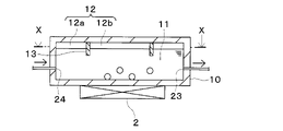
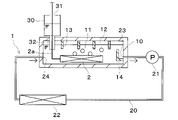
図1に示すように、本実施形態の冷却装置1は、電子機器2を冷却するための冷却槽10が設けられている。電子機器2は、作動に伴って発熱し、冷却を必要とする発熱体である。電子機器2としては、例えば発熱素子が搭載された電子基板やインバータ等を用いることができる。電子機器2が本開示の発熱体に相当している。
As shown in FIG. 1, the cooling device 1 of this embodiment is provided with a cooling bath 10 for cooling the electronic device 2 . The electronic device 2 is a heating element that generates heat as it operates and requires cooling. As the electronic device 2, for example, an electronic board on which a heating element is mounted, an inverter, or the like can be used. The electronic device 2 corresponds to the heating element of the present disclosure.
冷却槽10は、電子機器2を冷却するための冷媒液11が貯蔵されている容器状部材である。冷媒液11は、電子機器2の発熱で気相変化する流体であればよく、例えば水やフッ素系不活性液体を用いることができる。
The cooling bath 10 is a container-like member in which a refrigerant liquid 11 for cooling the electronic device 2 is stored. The refrigerant liquid 11 may be any fluid that undergoes a gas phase change due to the heat generated by the electronic device 2, and for example, water or fluorine-based inert liquid can be used.
本実施形態の冷却槽10は、大気と連通していない液密構造となっている。冷却槽10の内部は冷媒液11の相変化によって圧力変動するため、冷却槽10は耐圧構造となっている。
The cooling bath 10 of this embodiment has a liquid-tight structure that does not communicate with the atmosphere. Since the pressure inside the cooling tank 10 fluctuates due to the phase change of the refrigerant liquid 11, the cooling tank 10 has a pressure-resistant structure.
本実施形態では、電子機器2は冷却槽10の外部に設けられている。電子機器2と冷却槽10内の冷媒液11との間で熱交換が可能となっていれば、電子機器2は冷却槽10の外部あるいは内部のいずれに設けられていてもよい。
In this embodiment, the electronic device 2 is provided outside the cooling bath 10 . As long as heat can be exchanged between the electronic device 2 and the refrigerant liquid 11 in the cooling tank 10 , the electronic device 2 may be provided either outside or inside the cooling tank 10 .
電子機器2を冷却槽10の外部に設ける場合には、冷却槽10の壁面を介して電子機器2と冷媒液11との間の熱交換が行われるので、電子機器2は冷却槽10の壁面に接するように配置される。図1に示す例では、電子機器2は、冷却槽10の下面に接するように配置されている。
When the electronic device 2 is provided outside the cooling tank 10 , heat is exchanged between the electronic device 2 and the refrigerant liquid 11 through the wall surface of the cooling tank 10 . are placed in contact with the In the example shown in FIG. 1 , the electronic device 2 is arranged so as to be in contact with the lower surface of the cooling bath 10 .
電子機器2と冷却槽10の壁面との間には、熱伝導シート等を介在させることが望ましい。熱伝導シートは、電子機器2と冷却槽10の密着性を向上させ、電子機器2と冷却槽10と間の熱伝達率を向上させることができる。
It is desirable to interpose a heat conductive sheet or the like between the electronic device 2 and the wall surface of the cooling bath 10 . The heat conductive sheet can improve the adhesion between the electronic device 2 and the cooling bath 10 and improve the heat transfer coefficient between the electronic device 2 and the cooling bath 10 .
冷却槽10は、例えば金属材料や樹脂材料によって構成することができる。本実施形態では、冷却槽10として熱伝導率が高い金属材料を用いている。本実施形態のように、電子機器2を冷却槽10の外部に設ける場合には、冷却槽10として熱伝導率が高い金属材料を用いることで、冷却槽10の壁面を介した電子機器2と冷媒液11との間の熱交換効率を向上させることができる。
The cooling bath 10 can be made of, for example, a metal material or a resin material. In this embodiment, a metal material having high thermal conductivity is used as the cooling bath 10 . When the electronic device 2 is provided outside the cooling bath 10 as in the present embodiment, by using a metal material with high thermal conductivity as the cooling bath 10, the electronic device 2 and the electronic device 2 can be The heat exchange efficiency with the refrigerant liquid 11 can be improved.
冷媒液11の沸点は、電子機器2の発熱温度よりも低くなっている。このため、電子機器2の発熱で冷媒液11は沸騰可能となっており、冷却槽10では冷媒液11が沸騰して電子機器2から吸熱する沸騰冷却が行われる。本実施形態では、冷却槽10の冷媒液11が沸点より低温のサブクール液となっている状態で沸騰するサブクール沸騰が行われる。
The boiling point of the refrigerant liquid 11 is lower than the heat generation temperature of the electronic device 2 . Therefore, the refrigerant liquid 11 can be boiled by the heat generated by the electronic device 2 , and boiling cooling is performed in which the refrigerant liquid 11 boils in the cooling tank 10 and absorbs heat from the electronic device 2 . In this embodiment, subcooled boiling is performed in which the refrigerant liquid 11 in the cooling tank 10 boils in a subcooled liquid having a temperature lower than the boiling point.
冷媒液11が沸騰して発生した気相冷媒はサブクール液で凝縮、縮小するが、凝縮できない気泡が冷媒液11の内部を上方に移動する。冷却槽10の内部で発生した気体が冷却槽10内の上部で貯留されることで気体部12が形成される。気体部12には、気相冷媒、冷媒液11から放出された溶存ガス、初期から冷却槽10に存在する空気などが含まれている。気体部12の体積は変動可能となっており、体積ゼロになることもある。
The vapor-phase refrigerant generated by boiling the refrigerant liquid 11 condenses and shrinks in the subcooled liquid, but bubbles that cannot be condensed move upward inside the refrigerant liquid 11 . The gas generated inside the cooling tank 10 is stored in the upper part of the cooling tank 10 to form the gas portion 12 . The gas portion 12 includes gas-phase refrigerant, dissolved gas released from the refrigerant liquid 11, air present in the cooling tank 10 from the beginning, and the like. The volume of the gas portion 12 is variable and may become zero.
気体部12に含まれる気相冷媒は、冷却槽10の内部で冷媒液11が気化することで生成される。冷媒液11の気化には、冷媒液11の沸騰と蒸発が含まれている。気体部12に含まれる気相冷媒は、凝縮することで液相の冷媒液11となる。
The gas-phase refrigerant contained in the gas portion 12 is generated by evaporating the refrigerant liquid 11 inside the cooling tank 10 . Vaporization of the refrigerant liquid 11 includes boiling and evaporation of the refrigerant liquid 11 . The gas-phase refrigerant contained in the gas portion 12 becomes the liquid-phase refrigerant liquid 11 by condensing.
冷媒液11には、主に大気からなる溶存ガスが溶解している。気体部12に含まれる溶存ガスは、冷媒液11に溶解している溶存ガスが冷媒液11から放出されることで生成する。冷媒液11に溶解している溶存ガスの溶解度は、冷媒液11の温度等によって変動する。冷媒液11の温度が上昇すると溶存ガスの溶解度が低下し、溶存ガスが冷媒液11から放出される。冷媒液11から放出された溶存ガスは気相冷媒とともに気体部12を形成する。気体部12に含まれる溶存ガスは、冷媒液11の温度低下によって冷媒液11に再度溶解することができる。
Dissolved gas mainly composed of the atmosphere is dissolved in the refrigerant liquid 11 . The dissolved gas contained in the gas portion 12 is generated when the dissolved gas dissolved in the refrigerant liquid 11 is released from the refrigerant liquid 11 . The solubility of the gas dissolved in the refrigerant liquid 11 varies depending on the temperature of the refrigerant liquid 11 and the like. As the temperature of the refrigerant liquid 11 rises, the solubility of the dissolved gas decreases and the dissolved gas is released from the refrigerant liquid 11 . The dissolved gas released from the refrigerant liquid 11 forms the gas portion 12 together with the gas-phase refrigerant. The dissolved gas contained in the gas portion 12 can be dissolved again in the refrigerant liquid 11 due to the temperature drop of the refrigerant liquid 11 .
冷却槽10には、伝熱部13が設けられている。伝熱部13は、冷却槽10の内部で冷媒液11と気体部12に跨るように配置されており、冷媒液11と気体部12との間の熱伝達を促進する。伝熱部13は、サブクール液である冷媒液11の冷熱を気体部12に伝え、気体部12に含まれる気相冷媒の凝縮を促進する凝縮促進部である。
A heat transfer section 13 is provided in the cooling bath 10 . The heat transfer part 13 is arranged so as to straddle the refrigerant liquid 11 and the gas part 12 inside the cooling tank 10 , and promotes heat transfer between the refrigerant liquid 11 and the gas part 12 . The heat transfer portion 13 is a condensation promoting portion that transfers cold heat of the refrigerant liquid 11, which is a subcooled liquid, to the gas portion 12 and promotes condensation of the gas-phase refrigerant contained in the gas portion 12. FIG.
伝熱部13として、熱伝達率に優れた材料を用いており、例えば金属板やヒートパイプ等を用いることができる。本実施形態では、伝熱部13として、アルミニウムや銅からなる金属板を用いている。
A material with excellent heat transfer coefficient is used as the heat transfer part 13, and for example, a metal plate, a heat pipe, or the like can be used. In this embodiment, a metal plate made of aluminum or copper is used as the heat transfer portion 13 .
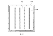
伝熱部13は、冷媒液11と気体部12を接続するように設けられていれば、配置場所は任意に設定することができる。本実施形態では、伝熱部13は冷却槽10の上面における内壁側に固定されている。伝熱部13は、冷却槽10の上面から重力方向下方に向かって延びるように設けられており、一部が気体部12に接触し、一部が冷媒液11に接触している。本実施形態では、4つの伝熱部13が設けられているが、伝熱部13の数は任意に設定でき、1つ以上設けられていればよい。
As long as the heat transfer section 13 is provided so as to connect the refrigerant liquid 11 and the gas section 12, the location can be set arbitrarily. In this embodiment, the heat transfer section 13 is fixed to the inner wall side of the upper surface of the cooling tank 10 . The heat transfer section 13 is provided so as to extend downward in the direction of gravity from the upper surface of the cooling bath 10 , and is partially in contact with the gas section 12 and partially in contact with the refrigerant liquid 11 . In this embodiment, four heat transfer parts 13 are provided, but the number of heat transfer parts 13 can be set arbitrarily, and one or more should be provided.
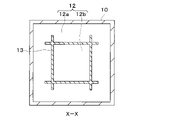
本実施形態では、伝熱部13は板状に形成されている。複数の伝熱部13は、並列して配置されている。伝熱部13の板面は、図1の紙面奥行方向および図2の紙面上下方向に延びるように配置されている。図1では、紙面奥行方向が伝熱部13の長手方向となっており、図2では、紙面上下方向が伝熱部13の長手方向となっている。
In this embodiment, the heat transfer section 13 is formed in a plate shape. A plurality of heat transfer parts 13 are arranged in parallel. The plate surface of the heat transfer section 13 is arranged so as to extend in the depth direction of the paper surface of FIG. 1 and in the vertical direction of the paper surface of FIG. 1, the depth direction of the paper is the longitudinal direction of the heat transfer section 13, and in FIG. 2, the vertical direction of the paper is the longitudinal direction of the heat transfer section 13. As shown in FIG.
図2に示すように、伝熱部13の長手方向端部は冷却槽10の内壁面に接触しておらず、伝熱部13の長手方向端部と冷却槽10の内壁面との間には隙間が設けられている。このため、冷却槽10の上部において、気体部12は伝熱部13によって仕切られておらず、気体部12は1つの空間となっている。
As shown in FIG. 2 , the longitudinal end of the heat transfer part 13 does not contact the inner wall surface of the cooling tank 10 , and there is a gap between the longitudinal end of the heat transfer part 13 and the inner wall surface of the cooling tank 10 . has a gap. Therefore, in the upper part of the cooling tank 10, the gas part 12 is not partitioned by the heat transfer part 13, and the gas part 12 is one space.
冷却槽10には、冷却槽10内の冷媒液11が循環する循環回路20が接続されている。循環回路20には、循環ポンプ21と熱交換器22が設けられている。
A circulation circuit 20 through which the refrigerant liquid 11 in the cooling tank 10 circulates is connected to the cooling tank 10 . A circulation pump 21 and a heat exchanger 22 are provided in the circulation circuit 20 .
循環ポンプ21は、冷媒液11を圧送して循環回路20に循環させ、冷媒液11を熱交換器22に供給する。熱交換器22は、冷媒液11の熱を放熱して冷却する。熱交換器22としては、例えば冷媒液11を外気と熱交換して冷却するラジエータ、あるいは冷媒液11を冷凍サイクルの低温冷媒と熱交換して冷却するチラー等を用いることができる。熱交換器22で冷媒液11を冷却することで、冷媒液11の温度上昇を抑制することができ、サブクール状態を維持することができる。
The circulation pump 21 pumps the refrigerant liquid 11 to circulate through the circulation circuit 20 and supplies the refrigerant liquid 11 to the heat exchanger 22 . The heat exchanger 22 radiates heat from the refrigerant liquid 11 to cool it. As the heat exchanger 22, for example, a radiator that cools the refrigerant liquid 11 by exchanging heat with the outside air, or a chiller that cools the refrigerant liquid 11 by exchanging heat with the low-temperature refrigerant of the refrigeration cycle, or the like can be used. By cooling the refrigerant liquid 11 with the heat exchanger 22, the temperature rise of the refrigerant liquid 11 can be suppressed, and the subcooled state can be maintained.
循環回路20は、冷媒液出口部23および冷媒液入口部24で冷却槽10と接続されている。冷却槽10の冷媒液11は、冷媒液出口部23を介して循環回路20に流出する。循環回路20を循環した冷媒液11は、冷媒液入口部24を介して冷却槽10に流入する。
The circulation circuit 20 is connected to the cooling bath 10 at a refrigerant liquid outlet portion 23 and a refrigerant liquid inlet portion 24 . The refrigerant liquid 11 in the cooling tank 10 flows out to the circulation circuit 20 through the refrigerant liquid outlet portion 23 . The refrigerant liquid 11 that has circulated through the circulation circuit 20 flows into the cooling tank 10 via the refrigerant liquid inlet portion 24 .
冷却槽10の内部では、冷媒液入口部24から冷媒液出口部23に向かう冷媒液11の流れが形成される。図1に示す例では、冷却槽10の左側に冷媒液入口部24が設けられ、冷却槽10の右側に冷媒液出口部23が設けられている。このため、冷却槽10の内部で左側から右側に向かう冷媒液11の流れが形成される。
Inside the cooling tank 10 , a flow of the refrigerant liquid 11 is formed from the refrigerant liquid inlet section 24 toward the refrigerant liquid outlet section 23 . In the example shown in FIG. 1 , a refrigerant liquid inlet portion 24 is provided on the left side of the cooling bath 10 and a refrigerant liquid outlet portion 23 is provided on the right side of the cooling bath 10 . Therefore, a flow of the refrigerant liquid 11 from left to right is formed inside the cooling tank 10 .
次に、上記構成を備える本実施形態の冷却装置1の作動について説明する。
Next, the operation of the cooling device 1 of this embodiment having the above configuration will be described.
冷却槽10の内部では、電子機器2の発熱によって冷媒液11が沸騰し、気相冷媒が発生する。本実施形態では、冷却槽10の下面を介して電子機器2と冷媒液11が熱交換するため、冷却槽10の下面と接触する冷媒液11が沸騰する。
Inside the cooling tank 10, the heat generated by the electronic device 2 causes the refrigerant liquid 11 to boil, generating a vapor phase refrigerant. In the present embodiment, heat is exchanged between the electronic device 2 and the refrigerant liquid 11 via the lower surface of the cooling tank 10, so the refrigerant liquid 11 in contact with the lower surface of the cooling tank 10 boils.
沸騰で生成した気相冷媒は、気泡として冷媒液11の中を上昇する。冷却槽10の冷媒液11はサブクール液であるため、気相冷媒からなる気泡は冷媒液11の内部を上昇する際に冷媒液11で冷却され、気相冷媒は凝縮する。この結果、気相冷媒からなる気泡は冷媒液11の内部を上昇する途中で縮小し、冷媒液11のサブクール度が大きい場合には気泡は消滅する。
The vapor-phase refrigerant generated by boiling rises in the refrigerant liquid 11 as bubbles. Since the refrigerant liquid 11 in the cooling tank 10 is a sub-cooled liquid, the air bubbles made of the vapor-phase refrigerant are cooled by the refrigerant liquid 11 when rising inside the refrigerant liquid 11, and the vapor-phase refrigerant is condensed. As a result, the bubbles made of the gas-phase refrigerant shrink while rising inside the refrigerant liquid 11, and when the degree of subcooling of the refrigerant liquid 11 is large, the bubbles disappear.
冷却槽10の内部を上昇した気相冷媒は、気体部12を形成する。冷媒液11の温度上昇によって冷媒液11から放出された溶存ガスも、気相冷媒とともに気体部12を形成する。冷媒液11が気化した気相冷媒や冷媒液11から放出された溶存ガスは、冷却槽10の内部に貯留される。
The gas-phase refrigerant rising inside the cooling tank 10 forms the gas portion 12 . The dissolved gas released from the refrigerant liquid 11 due to the temperature rise of the refrigerant liquid 11 also forms the gas portion 12 together with the gas-phase refrigerant. The vapor-phase refrigerant obtained by vaporizing the refrigerant liquid 11 and the dissolved gas released from the refrigerant liquid 11 are stored inside the cooling tank 10 .
気体部12には、伝熱部13を介してサブクール液である冷媒液11の冷熱が伝えられる。このため、気体部12に含まれる気相冷媒は、伝熱部13を介して冷媒液11によって冷却され、凝縮が促進される。凝縮された気相冷媒は液化して、冷媒液11となる。
The cold heat of the refrigerant liquid 11, which is a subcooled liquid, is transmitted to the gas section 12 via the heat transfer section 13. Therefore, the gas-phase refrigerant contained in the gas portion 12 is cooled by the refrigerant liquid 11 via the heat transfer portion 13, thereby promoting condensation. The condensed gas-phase refrigerant is liquefied to become the refrigerant liquid 11 .
さらに、本実施形態では、冷却槽10が熱伝導率が高い金属材料から構成されている。このため、冷却槽10の壁面を介することによっても、気体部12に冷媒液11の冷熱が伝えられ、気体部12に含まれる気相冷媒の凝縮が促進される。
Furthermore, in this embodiment, the cooling bath 10 is made of a metal material with high thermal conductivity. Therefore, the cold heat of the refrigerant liquid 11 is transmitted to the gas portion 12 also through the wall surface of the cooling tank 10, and the condensation of the gas-phase refrigerant contained in the gas portion 12 is promoted.
冷却槽10の冷媒液11は、循環回路20を介して熱交換器22に供給され、熱交換器22で冷却される。熱交換器22による冷却で、冷媒液11は積極的にサブクール状態を維持することができる。
The refrigerant liquid 11 in the cooling tank 10 is supplied to the heat exchanger 22 via the circulation circuit 20 and cooled in the heat exchanger 22 . Cooling by the heat exchanger 22 can positively maintain the subcooled state of the refrigerant liquid 11 .
以上説明した本実施形態によれば、冷却槽10に冷媒液11と気体部12に跨るように伝熱部13を設け、冷媒液11と気体部12との間の熱伝達を促進している。このため、気体部12は伝熱部13を介してサブクール液である冷媒液11によって冷却され、気体部12に含まれる気相冷媒の凝縮を促進することができる。これにより、冷却槽10の内部で気体部12の体積が増大することを抑制でき、冷却槽10から気相冷媒が流出することを抑制できる。この結果、気体が循環ポンプ21や熱交換器22に流入することを抑制でき、循環ポンプ21や熱交換器22の性能が低下することを回避できる。
According to the present embodiment described above, the cooling tank 10 is provided with the heat transfer portion 13 so as to straddle the refrigerant liquid 11 and the gas portion 12, thereby promoting heat transfer between the refrigerant liquid 11 and the gas portion 12. . Therefore, the gas portion 12 is cooled by the refrigerant liquid 11, which is a subcooled liquid, through the heat transfer portion 13, and the condensation of the gas-phase refrigerant contained in the gas portion 12 can be promoted. Thereby, it is possible to suppress an increase in the volume of the gas portion 12 inside the cooling tank 10 , and it is possible to suppress an outflow of the gas-phase refrigerant from the cooling tank 10 . As a result, it is possible to suppress the gas from flowing into the circulation pump 21 and the heat exchanger 22, and to avoid the deterioration of the performance of the circulation pump 21 and the heat exchanger 22.
(第2実施形態)
次に、本開示の第2実施形態を図3~図10を用いて説明する。以下、上記第1実施形態と異なる部分についてのみ説明する。図3、5、7、8では、上から下に向かう方向が重力方向となっており、図4、6、8、10では、手前から奥に向かう方向が重力方向となっている。 (Second embodiment)
Next, a second embodiment of the present disclosure will be described using FIGS. 3 to 10. FIG. Only parts different from the first embodiment will be described below. In FIGS. 3, 5, 7, and 8, the direction of gravity is from top to bottom, and in FIGS. 4, 6, 8, and 10, the direction of gravity is from front to back.
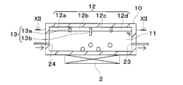
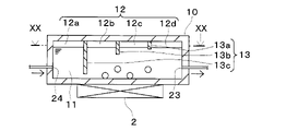
図3~図10に示すように、本第2実施形態では、冷却槽10において、伝熱部13によって気体部12が複数の領域に仕切られている。同時に、伝熱部13によって冷媒液11の液面も複数の領域に仕切られている。図3、4と、図5、6と、図7、8と、図9、10は、それぞれ本第2実施形態の伝熱部13の異なる態様を示している。
As shown in FIGS. 3 to 10, in the second embodiment, in the cooling tank 10, the gas portion 12 is partitioned into a plurality of regions by the heat transfer portion 13. As shown in FIG. At the same time, the liquid surface of the refrigerant liquid 11 is also divided into a plurality of areas by the heat transfer section 13 . FIGS. 3 and 4, FIGS. 5 and 6, FIGS. 7 and 8, and FIGS. 9 and 10 respectively show different aspects of the heat transfer section 13 of the second embodiment.
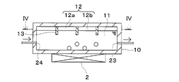
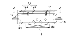
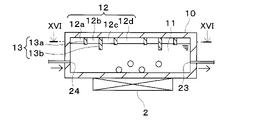
図3、図4に示す態様では、3つの伝熱部13が並列して設けられている。これらの伝熱部13のうち、1つの伝熱部13は長手方向の両端部が冷却槽10の内壁面に接触している。図4に示すように、長手方向の両端部が冷却槽10の内壁面に接触している伝熱部13によって、気体部12が第1気体部12aと第2気体部12bに仕切られている。
In the embodiments shown in FIGS. 3 and 4, three heat transfer sections 13 are provided in parallel. Of these heat transfer portions 13 , one heat transfer portion 13 is in contact with the inner wall surface of the cooling bath 10 at both ends in the longitudinal direction. As shown in FIG. 4, the gas portion 12 is partitioned into a first gas portion 12a and a second gas portion 12b by the heat transfer portion 13, which is in contact with the inner wall surface of the cooling tank 10 at both ends in the longitudinal direction. .
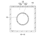
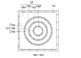
図5、図6に示す態様では、1つの伝熱部13が設けられている。伝熱部13は、重力方向からみて円形状に形成されている。図6に示すように、円形状の伝熱部13によって、気体部12が第1気体部12aと第2気体部12bに仕切られている。
In the embodiments shown in FIGS. 5 and 6, one heat transfer section 13 is provided. The heat transfer portion 13 is formed in a circular shape when viewed from the direction of gravity. As shown in FIG. 6, the circular heat transfer section 13 divides the gas section 12 into a first gas section 12a and a second gas section 12b.
図7、図8に示す態様では、1つの伝熱部13が設けられている。伝熱部13は、重力方向からみて四角形状に形成されている。図8に示すように、四角形状の伝熱部13によって、気体部12が第1気体部12aと第2気体部12bに仕切られている。
In the embodiments shown in FIGS. 7 and 8, one heat transfer section 13 is provided. The heat transfer portion 13 is formed in a square shape when viewed from the direction of gravity. As shown in FIG. 8, the rectangular heat transfer section 13 partitions the gas section 12 into a first gas section 12a and a second gas section 12b.
図9、図10に示す態様では、1つの伝熱部13が設けられている。伝熱部13は、重力方向からみて四角形部分を含む形状に形成されている。伝熱部13は、四角形を構成する各辺の両端が四角形の角部から延長された形状となっている。図10に示すように、四角形部分の伝熱部13によって、気体部12が第1気体部12aと第2気体部12bに仕切られている。
In the embodiments shown in FIGS. 9 and 10, one heat transfer section 13 is provided. The heat transfer portion 13 is formed in a shape including a square portion when viewed from the direction of gravity. The heat transfer portion 13 has a shape in which both ends of each side forming a quadrangle are extended from the corners of the quadrangle. As shown in FIG. 10, the gas portion 12 is partitioned into a first gas portion 12a and a second gas portion 12b by the rectangular heat transfer portion 13. As shown in FIG.
以上説明した本第2実施形態では、伝熱部13によって、気体部12が複数の領域に仕切られており、冷媒液11の液面が複数の領域に仕切られている。このため、冷却槽10が傾斜したり、振動した場合であっても、冷却槽10の内部で気体部12が片寄ることを抑制でき、冷媒液11の液面が振動することを抑制できる。これにより、冷却槽10から気相冷媒が流出し、気体が循環ポンプ21や熱交換器22に流入することを抑制でき、循環ポンプ21や熱交換器22の性能が低下することを回避できる。
In the second embodiment described above, the gas portion 12 is partitioned into a plurality of regions by the heat transfer portion 13, and the liquid surface of the refrigerant liquid 11 is partitioned into a plurality of regions. Therefore, even if the cooling tank 10 tilts or vibrates, it is possible to prevent the gas portion 12 from becoming one-sided inside the cooling tank 10 and to prevent the liquid surface of the refrigerant liquid 11 from vibrating. As a result, it is possible to prevent the gas-phase refrigerant from flowing out of the cooling tank 10 and the gas from flowing into the circulation pump 21 and the heat exchanger 22 , thereby avoiding deterioration in the performance of the circulation pump 21 and the heat exchanger 22 .
また、本第2実施形態を電子機器2が冷却槽10の内部で冷媒液11に浸漬されている構成に適用した場合には、冷却槽10が振動したり、傾斜しても、電子機器2が冷媒液11から露出することを抑制できる。この結果、電子機器2の冷却効率が低下することを抑制できる。
Further, when the second embodiment is applied to a configuration in which the electronic device 2 is immersed in the refrigerant liquid 11 inside the cooling tank 10, even if the cooling tank 10 vibrates or tilts, the electronic device 2 can be suppressed from being exposed from the refrigerant liquid 11 . As a result, it is possible to prevent the cooling efficiency of the electronic device 2 from decreasing.
(第3実施形態)
次に、本開示の第3実施形態を図11~図18を用いて説明する。以下、上記各実施形態と異なる部分についてのみ説明する。図11、13、15、17では、上から下に向かう方向が重力方向となっており、図12、14、16、18では、手前から奥に向かう方向が重力方向となっている。 (Third embodiment)
Next, a third embodiment of the present disclosure will be described with reference to FIGS. 11 to 18. FIG. Only parts different from the above embodiments will be described below. In FIGS. 11, 13, 15, and 17, the direction of gravity is from top to bottom, and in FIGS. 12, 14, 16, and 18, the direction of gravity is from front to back.
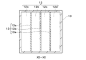
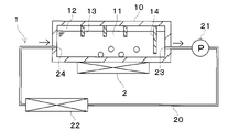
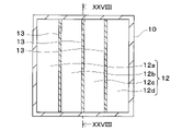
図11~図18に示すように、本第3実施形態では、冷却槽10において、複数の伝熱部13によって気体部12が複数の領域に仕切られている。同時に、複数の伝熱部13によって冷媒液11の液面も複数の領域に仕切られている。複数の伝熱部13には、重力方向長さが異なる複数の伝熱部13a、13bが含まれている。図11、12と、図13、14と、図15、16と、図17、18は、それぞれ本第3実施形態の伝熱部13の異なる態様を示している。
As shown in FIGS. 11 to 18, in the third embodiment, in the cooling bath 10, the gas portion 12 is partitioned into a plurality of regions by a plurality of heat transfer portions 13. As shown in FIGS. At the same time, the liquid surface of the refrigerant liquid 11 is also partitioned into a plurality of areas by the plurality of heat transfer portions 13 . The plurality of heat transfer portions 13 includes a plurality of heat transfer portions 13a and 13b having different lengths in the direction of gravity. 11 and 12, FIGS. 13 and 14, FIGS. 15 and 16, and FIGS. 17 and 18 show different aspects of the heat transfer section 13 of the third embodiment.
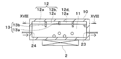
図11、図12に示す態様では、3つの伝熱部13が並列して設けられている。これらの伝熱部13は、長手方向の両端部が冷却槽10の内壁面に接触している。このため、3つの伝熱部13によって、気体部12が4つの気体部12a~12dに仕切られている。
In the embodiments shown in FIGS. 11 and 12, three heat transfer sections 13 are provided in parallel. These heat transfer portions 13 are in contact with the inner wall surface of the cooling bath 10 at both ends in the longitudinal direction. Therefore, the three heat transfer sections 13 divide the gas section 12 into four gas sections 12a to 12d.
図13、図14に示す態様では、重力方向からみて円形状に形成された3つの伝熱部13が設けられている。3つの伝熱部13は、それぞれ大きさが異なる同心円であり、所定間隔を設けて配置されている。このため、3つの伝熱部13によって、気体部12が4つの気体部12a~12dに仕切られている。
In the embodiment shown in FIGS. 13 and 14, three heat transfer parts 13 are provided which are formed in a circular shape when viewed from the direction of gravity. The three heat transfer portions 13 are concentric circles with different sizes, and are arranged at predetermined intervals. Therefore, the three heat transfer sections 13 divide the gas section 12 into four gas sections 12a to 12d.
図15、図16に示す態様では、重力方向からみて四角形状に形成された3つの伝熱部13が設けられている。3つの伝熱部13は、それぞれ大きさが異なっており、所定間隔を設けて配置されている。このため、3つの伝熱部13によって、気体部12が4つの気体部12a~12dに仕切られている。
In the embodiment shown in FIGS. 15 and 16, there are provided three heat transfer portions 13 each having a square shape when viewed from the direction of gravity. The three heat transfer parts 13 have different sizes and are arranged at predetermined intervals. Therefore, the three heat transfer sections 13 divide the gas section 12 into four gas sections 12a to 12d.
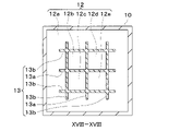
図17、図18に示す態様では、6つの伝熱部13が設けられており、並列する3つの伝熱部13と、別の並列する3つの伝熱部13が直交して配置されている。これらの6つの伝熱部13によって、気体部12が5つの気体部12a~12eに仕切られている。
In the embodiment shown in FIGS. 17 and 18, six heat transfer sections 13 are provided, and three parallel heat transfer sections 13 and another three parallel heat transfer sections 13 are arranged orthogonally. . These six heat transfer sections 13 partition the gas section 12 into five gas sections 12a to 12e.
図11、図13、図15、図17に示すように、本第3実施形態の伝熱部13には、重力方向長さが異なる第1伝熱部13aと第2伝熱部13bが含まれている。第1伝熱部13aと第2伝熱部13bは、隣り合って配置されている。第1伝熱部13aは、第2伝熱部13bよりも重力方向長さが短くなっている。第1伝熱部13aは、長手方向の全体の重力方向長さが第2伝熱部13bよりも短くなっていてもよく、長手方向の一部の重力方向長さが第2伝熱部13bよりも短くなっていてもよい。
As shown in FIGS. 11, 13, 15, and 17, the heat transfer section 13 of the third embodiment includes a first heat transfer section 13a and a second heat transfer section 13b having different lengths in the direction of gravity. is The first heat transfer portion 13a and the second heat transfer portion 13b are arranged adjacent to each other. The first heat transfer portion 13a has a shorter length in the direction of gravity than the second heat transfer portion 13b. The first heat transfer portion 13a may have a gravity direction length in the entire longitudinal direction shorter than that of the second heat transfer portion 13b, and a part of the longitudinal direction length in the gravity direction may be shorter than that of the second heat transfer portion 13b. may be shorter than
図11、図13、図15に示す例では、第1気体部12aおよび第2気体部12bは、重力方向長さが短い第1伝熱部13aによって仕切られていることから、互いにつながりやすくなっている。同様に、第3気体部12cおよび第4気体部12dも、第1伝熱部13aによって仕切られていることから、つながりやすくなっている。
In the examples shown in FIGS. 11, 13, and 15, the first gas portion 12a and the second gas portion 12b are separated by the first heat transfer portion 13a having a short length in the direction of gravity, so that they are easily connected to each other. ing. Similarly, the third gas portion 12c and the fourth gas portion 12d are also easily connected because they are separated by the first heat transfer portion 13a.
図17に示す例では、第2気体部12b、第3気体部12c、第4気体部12dおよび第5気体部12eは、重力方向長さが短い第1伝熱部13aによって仕切られていることから、互いにつながりやすくなっている。
In the example shown in FIG. 17, the second gas section 12b, the third gas section 12c, the fourth gas section 12d, and the fifth gas section 12e are partitioned by the first heat transfer section 13a having a short length in the direction of gravity. Therefore, it is easier to connect with each other.
上述のように本第3実施形態では、複数の伝熱部13によって複数の気体部12a~12eに仕切られている。伝熱部13で仕切られた気体部12a~12eでは、体積のばらつきが生じやすくなる。
As described above, in the third embodiment, the plurality of heat transfer sections 13 are divided into the plurality of gas sections 12a to 12e. In the gas portions 12a to 12e partitioned by the heat transfer portion 13, variations in volume are likely to occur.
これに対し、本第3実施形態では、重力方向長さが異なる第1伝熱部13aと第2伝熱部13bを設けることで、重力方向長さが短い第1伝熱部13aで仕切られている気体部同士をつながりやすくしている。これにより、複数の伝熱部13によって複数の気体部12a~12eに仕切られている場合であっても、複数の気体部12a~12eの体積がばらつくことを抑制できる。
In contrast, in the third embodiment, by providing the first heat transfer section 13a and the second heat transfer section 13b having different lengths in the direction of gravity, the first heat transfer section 13a having the short length in the direction of gravity is partitioned. It makes it easy to connect the gas parts that are in contact with each other. Accordingly, even when the plurality of gas portions 12a to 12e are partitioned by the plurality of heat transfer portions 13, it is possible to suppress variations in the volumes of the plurality of gas portions 12a to 12e.
(第4実施形態)
次に、本開示の第4実施形態を図19、図20を用いて説明する。以下、上記各実施形態と異なる部分についてのみ説明する。図19では、上から下に向かう方向が重力方向となっており、図20では、手前から奥に向かう方向が重力方向となっている。 (Fourth embodiment)
Next, a fourth embodiment of the present disclosure will be described with reference to FIGS. 19 and 20. FIG. Only parts different from the above embodiments will be described below. In FIG. 19, the direction from top to bottom is the direction of gravity, and in FIG. 20, the direction from front to back is the direction of gravity.
図19、図20に示すように、本第4実施形態では、冷却槽10において、複数の伝熱部13によって気体部12が複数の領域に仕切られている。同時に、複数の伝熱部13によって冷媒液11の液面も複数の領域に仕切られている。複数の伝熱部13には、重力方向長さが異なる第1伝熱部13a、第2伝熱部13bおよび第3伝熱部13cが含まれている。これらの伝熱部13a~13cは、第1伝熱部13a、第2伝熱部13b、第3伝熱部13cの順に重力方向長さが長くなっている。
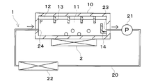
As shown in FIGS. 19 and 20, in the fourth embodiment, in the cooling bath 10, the gas portion 12 is partitioned into a plurality of regions by a plurality of heat transfer portions 13. FIG. At the same time, the liquid surface of the refrigerant liquid 11 is also partitioned into a plurality of areas by the plurality of heat transfer portions 13 . The plurality of heat transfer portions 13 includes a first heat transfer portion 13a, a second heat transfer portion 13b, and a third heat transfer portion 13c having different lengths in the direction of gravity. These heat transfer portions 13a to 13c are longer in the direction of gravity in the order of the first heat transfer portion 13a, the second heat transfer portion 13b, and the third heat transfer portion 13c.
図19に示すように、3つの伝熱部13a~13cのなかで、第3伝熱部13cは冷媒液入口部24に最も近接して配置されている。第3伝熱部13cは、冷媒液入口部24に対向するように設けられている。第3伝熱部13cは板状であり、板面が冷媒液入口部24に対向している。循環回路20の冷媒液入口部24および冷媒液出口部23を結ぶ方向からみて、第3伝熱部13cは冷媒液入口部24と重なり合っている。
As shown in FIG. 19, among the three heat transfer portions 13a to 13c, the third heat transfer portion 13c is arranged closest to the refrigerant liquid inlet portion . The third heat transfer portion 13 c is provided so as to face the refrigerant liquid inlet portion 24 . The third heat transfer portion 13 c has a plate shape, and the plate surface faces the refrigerant liquid inlet portion 24 . The third heat transfer portion 13 c overlaps the refrigerant liquid inlet portion 24 when viewed from the direction connecting the refrigerant liquid inlet portion 24 and the refrigerant liquid outlet portion 23 of the circulation circuit 20 .
以上説明した本第4実施形態によれば、冷媒液入口部24に対向するように設けられた第3伝熱部13cによって、循環回路20から冷媒液入口部24を介して冷却槽10の内部に流入した冷媒液11の流れが妨げられる。このため、冷却槽10の内部において、冷媒液入口部24から冷媒液出口部23に向かう冷媒液11の流れが緩和される。これにより、冷媒液11が沸騰して生成した気泡が冷媒液出口部23に向かって流れにくくなり、冷却槽10から気相冷媒が流出することを抑制できる。この結果、気体が循環ポンプ21や熱交換器22に流入することを抑制でき、循環ポンプ21や熱交換器22の性能が低下することを回避できる。
According to the fourth embodiment described above, the inside of the cooling tank 10 is heated from the circulation circuit 20 through the refrigerant liquid inlet section 24 by the third heat transfer section 13 c provided so as to face the refrigerant liquid inlet section 24 . The flow of the refrigerant liquid 11 flowing into is blocked. Therefore, the flow of the refrigerant liquid 11 from the refrigerant liquid inlet portion 24 toward the refrigerant liquid outlet portion 23 is moderated inside the cooling tank 10 . This makes it difficult for bubbles generated by the boiling of the refrigerant liquid 11 to flow toward the refrigerant liquid outlet portion 23 , thereby suppressing the gas-phase refrigerant from flowing out of the cooling tank 10 . As a result, it is possible to suppress the gas from flowing into the circulation pump 21 and the heat exchanger 22, and to avoid the deterioration of the performance of the circulation pump 21 and the heat exchanger 22.
(第5実施形態)
次に、本開示の第5実施形態を図21~図23を用いて説明する。以下、上記各実施形態と異なる部分についてのみ説明する。 (Fifth embodiment)
Next, a fifth embodiment of the present disclosure will be described with reference to FIGS. 21-23. Only parts different from the above embodiments will be described below.
次に、本開示の第5実施形態を図21~図23を用いて説明する。以下、上記各実施形態と異なる部分についてのみ説明する。 (Fifth embodiment)
Next, a fifth embodiment of the present disclosure will be described with reference to FIGS. 21-23. Only parts different from the above embodiments will be described below.
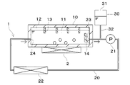
図21~図23に示すように、本第5実施形態では、冷却槽10の内部において、冷媒液出口部23に対向するように出口対向壁部14が設けられている。出口対向壁部14は板状に形成されており、板面が冷媒液出口部23に対向するように配置されている。出口対向壁部14は、例えば金属材料や樹脂材料によって構成することができる。図21、図22、図23は、それぞれ本第5実施形態の出口対向壁部14の異なる態様を示している。
As shown in FIGS. 21 to 23, in the fifth embodiment, an outlet facing wall portion 14 is provided inside the cooling tank 10 so as to face the refrigerant liquid outlet portion 23 . The outlet facing wall portion 14 is formed in a plate shape, and is arranged so that the plate surface faces the refrigerant liquid outlet portion 23 . The outlet facing wall portion 14 can be made of, for example, a metal material or a resin material. 21, 22, and 23 show different aspects of the outlet-facing wall portion 14 of the fifth embodiment.
図21に示す態様では、出口対向壁部14が断面L字状に屈曲した板状に形成されている。出口対向壁部14は、冷却槽10における冷媒液出口部23が形成された側面に設けられている。
In the embodiment shown in FIG. 21, the outlet-facing wall portion 14 is formed in a plate shape with an L-shaped cross section. The outlet facing wall portion 14 is provided on the side surface of the cooling tank 10 where the refrigerant liquid outlet portion 23 is formed.
図22、図23に示す態様では、出口対向壁部14が1枚の板状に形成されている。図22に示す態様では、出口対向壁部14は冷却槽10の底面から重力方向上方に延びるように設けられている。図23に示す態様では、出口対向壁部14は冷却槽10の上面から重力方向下方に延びるように設けられている。図23の出口対向壁部14は、冷媒液11と気体部12に跨るように設けられている。
In the embodiment shown in FIGS. 22 and 23, the outlet-facing wall portion 14 is formed into a single plate. In the embodiment shown in FIG. 22, the outlet facing wall portion 14 is provided so as to extend upward in the gravitational direction from the bottom surface of the cooling bath 10 . In the embodiment shown in FIG. 23, the outlet facing wall portion 14 is provided so as to extend downward in the gravitational direction from the upper surface of the cooling bath 10 . The outlet facing wall portion 14 in FIG. 23 is provided so as to straddle the refrigerant liquid 11 and the gas portion 12 .
以上説明した本第5実施形態によれば、冷媒液出口部23に対向するように設けられた出口対向壁部14によって、冷却槽10から冷媒液出口部23を介して循環回路20に流出する冷媒液11の流れが妨げられる。これにより、冷媒液11が沸騰して生成した気泡が冷媒液出口部23に向かって流れにくくなり、冷却槽10から気相冷媒が流出することを抑制できる。この結果、気体が循環ポンプ21や熱交換器22に流入することを抑制でき、循環ポンプ21や熱交換器22の性能が低下することを回避できる。
According to the fifth embodiment described above, the outlet facing wall portion 14 provided so as to face the refrigerant liquid outlet portion 23 causes the coolant to flow out from the cooling tank 10 to the circulation circuit 20 via the refrigerant liquid outlet portion 23 . The flow of refrigerant liquid 11 is impeded. This makes it difficult for bubbles generated by the boiling of the refrigerant liquid 11 to flow toward the refrigerant liquid outlet portion 23 , thereby suppressing the gas-phase refrigerant from flowing out of the cooling tank 10 . As a result, it is possible to suppress the gas from flowing into the circulation pump 21 and the heat exchanger 22, and to avoid the deterioration of the performance of the circulation pump 21 and the heat exchanger 22.
また、図23に示す出口対向壁部14は、冷媒液11と気体部12に跨るように設けられている。このため、出口対向壁部14として、熱伝達率に優れた材料(例えばアルミニウムや銅からなる金属版)を用いることで、冷媒液11と気体部12との間の熱伝達を促進させることができ、出口対向壁部14を伝熱部13として機能させることができる。
Further, the outlet facing wall portion 14 shown in FIG. 23 is provided so as to straddle the refrigerant liquid 11 and the gas portion 12 . Therefore, heat transfer between the refrigerant liquid 11 and the gas portion 12 can be promoted by using a material having a high heat transfer coefficient (for example, a metal plate made of aluminum or copper) for the outlet facing wall portion 14 . This allows the outlet-facing wall portion 14 to function as the heat transfer portion 13 .
(第6実施形態)
次に、本開示の第6実施形態を図24を用いて説明する。以下、上記各実施形態と異なる部分についてのみ説明する。 (Sixth embodiment)
Next, a sixth embodiment of the present disclosure will be described using FIG. Only parts different from the above embodiments will be described below.
次に、本開示の第6実施形態を図24を用いて説明する。以下、上記各実施形態と異なる部分についてのみ説明する。 (Sixth embodiment)
Next, a sixth embodiment of the present disclosure will be described using FIG. Only parts different from the above embodiments will be described below.
図24に示すように、本第6実施形態の冷却装置1には貯液槽30が設けられている。貯液槽30は、内部に冷媒液11を貯蔵可能な容器状部材である。貯液槽30の冷媒液11の液面は、冷却槽10の冷媒液11の液面よりも高くなっている。貯液槽30は、冷却槽10の外部に設けられている。本第6実施形態では、貯液槽30は循環回路20に接続されている。
As shown in FIG. 24, a liquid storage tank 30 is provided in the cooling device 1 of the sixth embodiment. The liquid storage tank 30 is a container-like member capable of storing the refrigerant liquid 11 therein. The liquid level of the refrigerant liquid 11 in the liquid storage tank 30 is higher than the liquid level of the refrigerant liquid 11 in the cooling tank 10 . The liquid storage tank 30 is provided outside the cooling tank 10 . In the sixth embodiment, the liquid storage tank 30 is connected to the circulation circuit 20 .
貯液槽30の上部には、大気開口部31が設けられている。貯液槽30の内部は、上方で大気開口部31を介して大気と連通している。貯液槽30は大気に開放されており、貯液槽30の内部では、冷媒液11の上部に大気が存在する。
An air opening 31 is provided at the top of the liquid storage tank 30 . The inside of the liquid storage tank 30 communicates with the atmosphere via an air opening 31 from above. The liquid storage tank 30 is open to the atmosphere, and the atmosphere exists above the refrigerant liquid 11 inside the liquid storage tank 30 .
貯液槽30は、接続部32によって循環回路20に連通している。接続部32は筒状部材であり、内部を冷媒液11が通過可能となっている。接続部32は、一端側が貯液槽30に接続され、他端側が循環回路20に接続されている。貯液槽30は、接続部32および循環回路20を介して冷却槽10と連通している。
The liquid storage tank 30 communicates with the circulation circuit 20 through a connecting portion 32 . The connecting portion 32 is a tubular member, through which the refrigerant liquid 11 can pass. The connecting portion 32 has one end connected to the liquid storage tank 30 and the other end connected to the circulation circuit 20 . The liquid storage tank 30 communicates with the cooling tank 10 via the connecting portion 32 and the circulation circuit 20 .
貯液槽30は大気開口部31を介して大気に開放しており、冷却槽10は貯液槽30の大気開口部31を介して大気に開放している。このため、貯液槽30の内部および冷却槽10の内部は大気圧に維持される。
The liquid storage tank 30 is open to the atmosphere through the atmospheric opening 31 , and the cooling tank 10 is open to the atmosphere through the atmospheric opening 31 of the liquid storage tank 30 . Therefore, the inside of the liquid storage tank 30 and the inside of the cooling tank 10 are maintained at atmospheric pressure.
冷却槽10の内部と貯液槽30の内部は連通しており、冷媒液11は冷却槽10と貯液槽30との間を流動可能となっている。冷媒液11は、気体部12の体積変動に応じて、冷却槽10と貯液槽30との間を流動する。
The inside of the cooling tank 10 and the inside of the liquid storage tank 30 communicate with each other, so that the refrigerant liquid 11 can flow between the cooling tank 10 and the liquid storage tank 30 . The refrigerant liquid 11 flows between the cooling tank 10 and the liquid storage tank 30 according to the volume change of the gas portion 12 .
冷却槽10と貯液槽30との間を冷媒液11が流動することで、冷却槽10の冷媒液11の体積と貯液槽30の冷媒液11の体積は連動して変動する。具体的には、冷却槽10の冷媒液11の体積が減少すると、貯液槽30の冷媒液11の体積が増大する。冷却槽10の冷媒液11の体積が増大すると、貯液槽30の冷媒液11の体積が減少する。
As the refrigerant liquid 11 flows between the cooling tank 10 and the liquid storage tank 30, the volume of the refrigerant liquid 11 in the cooling tank 10 and the volume of the refrigerant liquid 11 in the liquid storage tank 30 interlock and fluctuate. Specifically, when the volume of the refrigerant liquid 11 in the cooling tank 10 decreases, the volume of the refrigerant liquid 11 in the liquid storage tank 30 increases. As the volume of the refrigerant liquid 11 in the cooling tank 10 increases, the volume of the refrigerant liquid 11 in the liquid storage tank 30 decreases.
以上説明した本第6実施形態では、冷却槽10の外部に大気開口部31を有する貯液槽30を設け、冷却槽10と貯液槽30を連通させることで、貯液槽30によって冷却槽10の冷媒液11の体積変動を吸収することができる。冷却槽10は貯液槽30の大気開口部31を介して大気に開放されるため、冷却槽10を冷媒液11を封入するための耐圧構造とする必要がなく、小型化することができる。
In the sixth embodiment described above, the liquid storage tank 30 having the air opening 31 is provided outside the cooling tank 10, and the cooling tank 10 and the liquid storage tank 30 are communicated with each other. 10 can absorb the volume fluctuation of the refrigerant liquid 11 . Since the cooling tank 10 is open to the atmosphere through the atmospheric opening 31 of the liquid storage tank 30, the cooling tank 10 does not need to have a pressure-resistant structure for enclosing the refrigerant liquid 11, and the size can be reduced.
また、冷却槽10は直接大気に開放しておらず、冷却槽10で発生した気体は冷却槽10内の上部で貯留されて気体部12を形成する。このため、冷却槽10は大気開放式であるにもかかわらず、冷却槽10で発生した気体が冷却槽10から流出することを抑制できる。この結果、気体が循環ポンプ21や熱交換器22に流入することを抑制でき、循環ポンプ21や熱交換器22の性能が低下することを回避できる。
Also, the cooling tank 10 is not directly open to the atmosphere, and the gas generated in the cooling tank 10 is stored in the upper part of the cooling tank 10 to form the gas portion 12 . Therefore, although the cooling tank 10 is open to the atmosphere, the gas generated in the cooling tank 10 can be prevented from flowing out of the cooling tank 10 . As a result, it is possible to suppress the gas from flowing into the circulation pump 21 and the heat exchanger 22, and to avoid the deterioration of the performance of the circulation pump 21 and the heat exchanger 22.
(第7実施形態)
次に、本開示の第7実施形態を図25を用いて説明する。以下、上記各実施形態と異なる部分についてのみ説明する。本第7実施形態では、上記第6実施形態に対して、貯液槽30の配置が異なっている。 (Seventh embodiment)
Next, a seventh embodiment of the present disclosure will be described with reference to FIG. 25. FIG. Only parts different from the above embodiments will be described below. In the seventh embodiment, the arrangement of theliquid storage tank 30 is different from that in the sixth embodiment.
次に、本開示の第7実施形態を図25を用いて説明する。以下、上記各実施形態と異なる部分についてのみ説明する。本第7実施形態では、上記第6実施形態に対して、貯液槽30の配置が異なっている。 (Seventh embodiment)
Next, a seventh embodiment of the present disclosure will be described with reference to FIG. 25. FIG. Only parts different from the above embodiments will be described below. In the seventh embodiment, the arrangement of the
図25に示すように、本第7実施形態では、貯液槽30は冷却槽10に接続されている。本第7実施形態の接続部32は、一端側が貯液槽30に接続され、他端側が冷却槽10に接続されている。接続部32は、冷却槽10の上面を貫通するように設けられている。
As shown in FIG. 25, the liquid storage tank 30 is connected to the cooling tank 10 in the seventh embodiment. The connecting portion 32 of the seventh embodiment has one end connected to the liquid storage tank 30 and the other end connected to the cooling tank 10 . The connection part 32 is provided so as to penetrate the upper surface of the cooling bath 10 .
冷却槽10内の冷媒液11の液面は、通常は接続部32の冷却槽側端部よりも上方に位置しており、気体部12の体積増大時に接続部32の冷却槽側端部まで下降し得る。このため、接続部32の冷却槽側端部は、冷却槽10内の冷媒液11の液面より下側または同じ高さに位置している。
The liquid surface of the refrigerant liquid 11 in the cooling tank 10 is normally positioned above the cooling tank side end of the connection portion 32, and when the volume of the gas portion 12 increases, the liquid level of the refrigerant liquid 11 reaches the cooling tank side end of the connection portion 32. can go down. Therefore, the end of the connecting portion 32 on the cooling tank side is positioned below or at the same height as the liquid surface of the refrigerant liquid 11 in the cooling tank 10 .
冷却槽10において、冷媒液11の液面が接続部32の冷却槽側端部まで下降した状態で、新たに気体が発生した場合には、気体は接続部32を介して貯液槽30の大気開口部31から大気に放出される。このため、気体部12の体積は、冷媒液11の液面が接続部32の冷却槽側端部まで下降した状態から増大しない。
In the cooling tank 10 , when the liquid level of the refrigerant liquid 11 is lowered to the end of the connecting portion 32 on the cooling tank side, and new gas is generated, the gas flows into the liquid storage tank 30 via the connecting portion 32 . It is discharged to the atmosphere through the atmosphere opening 31 . Therefore, the volume of the gas portion 12 does not increase from the state in which the liquid surface of the refrigerant liquid 11 has fallen to the end of the connection portion 32 on the cooling tank side.
本第7実施形態では、接続部32の冷却槽側端部は、気相冷媒が流入しにくい位置に設けられている。具体的には、接続部32の冷却槽側端部は、冷却槽10における冷媒液11の流れ方向上流側に設けられている。つまり、接続部32の冷却槽側端部は、冷媒液11の流れ方向において、冷媒液出口部23よりも冷媒液入口部24に近い側に設けられている。
In the seventh embodiment, the end of the connecting portion 32 on the side of the cooling tank is provided at a position where it is difficult for the gas-phase refrigerant to flow. Specifically, the end of the connecting portion 32 on the cooling tank side is provided on the upstream side in the cooling tank 10 in the flow direction of the refrigerant liquid 11 . In other words, the cooling tank side end portion of the connection portion 32 is provided closer to the refrigerant liquid inlet portion 24 than the refrigerant liquid outlet portion 23 in the flow direction of the refrigerant liquid 11 .
以上説明した本第7実施形態では、冷却槽10の冷媒液11の体積変動を吸収する貯液槽30を冷却槽10に接続するように設けている。これにより、貯液槽30を循環回路20に接続した上記第6実施形態に比較して、冷却槽10にかかる内部圧力を、循環回路20を流れる冷媒液11の圧力損失分低減することができる。
In the seventh embodiment described above, the liquid storage tank 30 that absorbs volume fluctuations of the refrigerant liquid 11 in the cooling tank 10 is provided so as to be connected to the cooling tank 10 . As a result, compared to the sixth embodiment in which the liquid storage tank 30 is connected to the circulation circuit 20, the internal pressure applied to the cooling tank 10 can be reduced by the pressure loss of the refrigerant liquid 11 flowing through the circulation circuit 20. .
また、本第7実施形態では、冷却槽10の内部で気体部12の体積が増大した場合に、余分な気体は接続部32を介して貯液槽30の大気開口部31から大気に放出される。このため、冷却槽10から気体が循環ポンプ21や熱交換器22に流入することを抑制でき、循環ポンプ21や熱交換器22の性能が低下することを回避できる。
Further, in the seventh embodiment, when the volume of the gas portion 12 inside the cooling tank 10 increases, excess gas is released to the atmosphere from the atmospheric opening 31 of the liquid storage tank 30 via the connecting portion 32. be. Therefore, it is possible to prevent the gas from flowing into the circulation pump 21 and the heat exchanger 22 from the cooling tank 10 , and to avoid the deterioration of the performance of the circulation pump 21 and the heat exchanger 22 .
また、本第7実施形態では、接続部32の冷却槽側端部を冷却槽10の冷媒液11の流れ方向上流側に設けている。気相冷媒からなる気泡は、冷媒液11の流れ方向下流側に移動しながら上昇するため、接続部32の冷却槽側端部から遠ざかりながら上昇する。このため、気相冷媒が冷媒液11の流れ方向上流側に設けられた接続部32の冷却槽側端部に流入することを抑制できる。これにより、冷却槽10の内部で発生した気相冷媒が接続部32の冷却槽側端部を介して貯液槽30の大気開口部31から外部に流出することを抑制でき、冷媒液11の減少を抑制できる。
In addition, in the seventh embodiment, the end of the connecting portion 32 on the cooling tank side is provided on the upstream side of the cooling tank 10 in the flow direction of the refrigerant liquid 11 . Since the bubbles made of the gas-phase refrigerant rise while moving downstream in the flow direction of the refrigerant liquid 11 , they rise while moving away from the end of the connecting portion 32 on the cooling tank side. Therefore, it is possible to suppress the gas-phase refrigerant from flowing into the cooling tank side end portion of the connecting portion 32 provided on the upstream side in the flow direction of the refrigerant liquid 11 . As a result, the gas-phase refrigerant generated inside the cooling tank 10 can be prevented from flowing out from the atmosphere opening 31 of the liquid storage tank 30 via the end of the connecting part 32 on the side of the cooling tank. Decrease can be suppressed.
(第8実施形態)
次に、本開示の第8実施形態を図26を用いて説明する。以下、上記各実施形態と異なる部分についてのみ説明する。図26では、上から下に向かう方向が重力方向となっている。本第8実施形態では、上記第7実施形態に対して、電子機器2の配置が異なっている。 (Eighth embodiment)
Next, an eighth embodiment of the present disclosure will be described using FIG. Only parts different from the above embodiments will be described below. In FIG. 26, the direction from top to bottom is the direction of gravity. In the eighth embodiment, the arrangement of theelectronic device 2 is different from that in the seventh embodiment.
次に、本開示の第8実施形態を図26を用いて説明する。以下、上記各実施形態と異なる部分についてのみ説明する。図26では、上から下に向かう方向が重力方向となっている。本第8実施形態では、上記第7実施形態に対して、電子機器2の配置が異なっている。 (Eighth embodiment)
Next, an eighth embodiment of the present disclosure will be described using FIG. Only parts different from the above embodiments will be described below. In FIG. 26, the direction from top to bottom is the direction of gravity. In the eighth embodiment, the arrangement of the
図26に示すように、本第8実施形態では、電子機器2が冷却槽10に収容されている。電子機器2は、冷却槽10の内部で冷媒液11に浸漬している。本第8実施形態では、冷媒液11としてフッ素系不活性液体を用いている。フッ素系不活性液体は、絶縁性、伝熱特性、安定性に優れた冷媒液である。
As shown in FIG. 26, the electronic device 2 is accommodated in the cooling bath 10 in the eighth embodiment. The electronic device 2 is immersed in the coolant liquid 11 inside the cooling bath 10 . In the eighth embodiment, a fluorine-based inert liquid is used as the refrigerant liquid 11 . A fluorine-based inert liquid is a refrigerant liquid that is excellent in insulating properties, heat transfer properties, and stability.
接続部32の冷却槽側端部は、重力方向において、電子機器2よりも上方に位置している。このため、冷却槽10の内部で冷媒液11が接続部32の冷却槽側端部まで下降しても、電子機器2は冷媒液11に浸漬された状態を維持できる。
The end of the connecting portion 32 on the cooling bath side is located above the electronic device 2 in the direction of gravity. Therefore, even if the coolant liquid 11 descends to the end of the connecting portion 32 on the cooling tank side inside the cooling tank 10 , the electronic device 2 can maintain the state of being immersed in the coolant liquid 11 .
本第8実施形態では、電子機器2が冷媒液11に浸漬しているため、電子機器2における冷媒液11との接触面すべてを冷却することができる。また、電子機器2が冷媒液11に浸漬しているため、電子機器2と冷媒液11との間に冷却槽10の壁面や伝熱シート等が介在することなく、電子機器2と冷媒液11が直接接触している。これにより、電子機器2の冷却効率を向上させることができる。
In the eighth embodiment, since the electronic device 2 is immersed in the refrigerant liquid 11, all contact surfaces of the electronic device 2 with the refrigerant liquid 11 can be cooled. In addition, since the electronic device 2 is immersed in the refrigerant liquid 11, the wall surface of the cooling tank 10, the heat transfer sheet, or the like does not intervene between the electronic device 2 and the refrigerant liquid 11. are in direct contact. Thereby, the cooling efficiency of the electronic device 2 can be improved.
(第9実施形態)
次に、本開示の第9実施形態を図27を用いて説明する。以下、上記各実施形態と異なる部分についてのみ説明する。本第9実施形態では、上記第8実施形態に対して、電子機器2の配線2aが設けられている点が異なっている。 (Ninth embodiment)
Next, a ninth embodiment of the present disclosure will be described using FIG. Only parts different from the above embodiments will be described below. The ninth embodiment differs from the eighth embodiment in that thewiring 2a of the electronic device 2 is provided.
次に、本開示の第9実施形態を図27を用いて説明する。以下、上記各実施形態と異なる部分についてのみ説明する。本第9実施形態では、上記第8実施形態に対して、電子機器2の配線2aが設けられている点が異なっている。 (Ninth embodiment)
Next, a ninth embodiment of the present disclosure will be described using FIG. Only parts different from the above embodiments will be described below. The ninth embodiment differs from the eighth embodiment in that the
図27に示すように、本第9実施形態では、電子機器2には配線2aが接続されている。配線2aは、電源や電気信号の伝送路として機能する。配線2aは、冷却槽10から接続部32および貯液槽30に延びるように設けられている。配線2aは、貯液槽30の大気開口部31から外部に取り出されている。
As shown in FIG. 27, in the ninth embodiment, the wiring 2a is connected to the electronic device 2. As shown in FIG. The wiring 2a functions as a transmission path for power supply and electrical signals. Wiring 2 a is provided so as to extend from cooling tank 10 to connecting portion 32 and liquid storage tank 30 . The wiring 2 a is taken out from the atmosphere opening 31 of the liquid storage tank 30 .
以上のように、本第9実施形態では、大気に開放した大気開口部31を利用して電子機器2の配線2aを外部に取り出している。このため、冷媒液11の外部流出を防ぐためのシール構造を設けることなく、電子機器2の配線2aを外部に取り出すことができる。
As described above, in the ninth embodiment, the wiring 2a of the electronic device 2 is taken out to the outside using the atmospheric opening 31 open to the atmosphere. Therefore, the wiring 2a of the electronic device 2 can be taken out to the outside without providing a sealing structure for preventing the refrigerant liquid 11 from flowing out to the outside.
(第10実施形態)
次に、本開示の第10実施形態を図28、図29を用いて説明する。以下、上記各実施形態と異なる部分についてのみ説明する。図28では、手前から奥に向かう方向が重力方向となっており、図29では、上から下に向かう方向が重力方向となっている。また、図29では、破線が冷媒液11の液面を示している。 (Tenth embodiment)
Next, a tenth embodiment of the present disclosure will be described with reference to FIGS. 28 and 29. FIG. Only parts different from the above embodiments will be described below. In FIG. 28, the direction of gravity is the direction from front to back, and in FIG. 29, the direction of gravity is the direction from top to bottom. Further, in FIG. 29 , the dashed line indicates the liquid surface of therefrigerant liquid 11 .
次に、本開示の第10実施形態を図28、図29を用いて説明する。以下、上記各実施形態と異なる部分についてのみ説明する。図28では、手前から奥に向かう方向が重力方向となっており、図29では、上から下に向かう方向が重力方向となっている。また、図29では、破線が冷媒液11の液面を示している。 (Tenth embodiment)
Next, a tenth embodiment of the present disclosure will be described with reference to FIGS. 28 and 29. FIG. Only parts different from the above embodiments will be described below. In FIG. 28, the direction of gravity is the direction from front to back, and in FIG. 29, the direction of gravity is the direction from top to bottom. Further, in FIG. 29 , the dashed line indicates the liquid surface of the
図28に示すように、本第10実施形態では、冷却槽10において、複数の伝熱部13によって気体部12が複数の領域に仕切られている。同時に、複数の伝熱部13によって冷媒液11の液面も複数の領域に仕切られている。本第10実施形態では、複数の伝熱部13は、同一の構成を有している。
As shown in FIG. 28, in the tenth embodiment, in the cooling bath 10, the gas portion 12 is partitioned into a plurality of regions by a plurality of heat transfer portions 13. As shown in FIG. At the same time, the liquid surface of the refrigerant liquid 11 is also partitioned into a plurality of areas by the plurality of heat transfer portions 13 . In the tenth embodiment, the plurality of heat transfer parts 13 have the same configuration.
図28に示す例では、3つの伝熱部13が並列して設けられている。これらの伝熱部13は、長手方向の両端部が冷却槽10の内壁面に接触している。このため、3つの伝熱部13によって、気体部12が4つの気体部12a~12dに仕切られている。
In the example shown in FIG. 28, three heat transfer parts 13 are provided in parallel. These heat transfer portions 13 are in contact with the inner wall surface of the cooling bath 10 at both ends in the longitudinal direction. Therefore, the three heat transfer sections 13 divide the gas section 12 into four gas sections 12a to 12d.
図29に示すように、本第10実施形態の伝熱部13は、重力方向下端部の位置が他の部位よりも高くなっている短手部13xを有している。短手部13xは、伝熱部13における他の部位より重力方向長さが短くなっている。短手部13xは、伝熱部13における重力方向下方の一部が切り欠かれた切欠部として構成されている。
As shown in FIG. 29, the heat transfer section 13 of the tenth embodiment has a short section 13x whose lower end in the direction of gravity is higher than other sections. The short part 13x has a length in the direction of gravity shorter than that of other parts of the heat transfer part 13 . The short portion 13x is configured as a notch portion obtained by notching a part of the heat transfer portion 13 downward in the direction of gravity.
隣接する第1気体部12aと第2気体部12b、隣接する第2気体部12bと第3気体部12c、隣接する第3気体部12cと第4気体部12dは、伝熱部13の短手部13xを介してつながりやすくなっている。
Adjacent first gas portion 12a and second gas portion 12b, adjacent second gas portion 12b and third gas portion 12c, and adjacent third gas portion 12c and fourth gas portion 12d It is easy to connect via the part 13x.
本第10実施形態のように、伝熱部13によって複数の気体部12a~12dに仕切られている構成では、複数の気体部12a~12dで体積のばらつきが生じやすくなる。これに対し、本第10実施形態では、伝熱部13に他の部位よりも重力方向長さが短い短手部13xを設けることで、短手部13xを介して隣接する気体部同士をつながりやすくしている。これにより、伝熱部13によって複数の気体部12a~12dに仕切られている場合であっても、複数の気体部12a~12dの体積がばらつくことを抑制できる。
In the configuration in which the heat transfer section 13 partitions the gas sections 12a to 12d into a plurality of gas sections 12a to 12d as in the tenth embodiment, the plurality of gas sections 12a to 12d are likely to vary in volume. On the other hand, in the tenth embodiment, the heat transfer portion 13 is provided with the short portion 13x having a shorter length in the direction of gravity than the other portions. making it easier. Accordingly, even when the heat transfer section 13 partitions the plurality of gas portions 12a to 12d into a plurality of gas portions 12a to 12d, it is possible to suppress variations in the volumes of the plurality of gas portions 12a to 12d.
本開示は上述の実施形態に限定されることなく、本開示の趣旨を逸脱しない範囲内で、以下のように種々変形可能である。また、上記各実施形態に開示された手段は、実施可能な範囲で適宜組み合わせてもよい。
The present disclosure is not limited to the above-described embodiments, and can be variously modified as follows without departing from the scope of the present disclosure. Moreover, the means disclosed in each of the above embodiments may be appropriately combined within the practicable range.
また、上記各実施形態では、伝熱部13を冷却槽10の上面から重力方向下方に延びるように設けたが、伝熱部13は冷却槽10の上面と必ずしも接触していなくてもよい。例えば、伝熱部13を冷媒液11と気体部12に跨るように冷却槽10の側壁に設け、伝熱部13と冷却槽10の上面との間に隙間が形成された状態とすることができる。あるいは、伝熱部13を冷媒液11と気体部12に跨るように冷媒液11の液面に浮遊するように設け、冷却槽10の上面との間に隙間が形成された状態とすることができる。
Also, in each of the above embodiments, the heat transfer section 13 is provided to extend downward in the direction of gravity from the upper surface of the cooling tank 10 , but the heat transfer section 13 does not necessarily have to be in contact with the upper surface of the cooling tank 10 . For example, the heat transfer part 13 may be provided on the side wall of the cooling tank 10 so as to straddle the refrigerant liquid 11 and the gas part 12, and a gap may be formed between the heat transfer part 13 and the upper surface of the cooling tank 10. can. Alternatively, the heat transfer portion 13 may be provided so as to float on the liquid surface of the liquid refrigerant 11 so as to straddle the liquid refrigerant 11 and the gas portion 12, and a gap may be formed between the heat transfer portion 13 and the upper surface of the cooling tank 10. can.
また、上記第6~第9実施形態の構成において、貯液槽30における冷媒液11の上面に蒸発防止剤を設けてもよい。貯液槽30における冷媒液11の上面は、大気との接触面である。蒸発防止剤は、冷媒液11の蒸発を抑制できればよく、例えば貯液槽30における冷媒液11の上面を覆う油膜用オイルや、貯液槽30における冷媒液11の上面を覆う粒子などを用いることができる。
Further, in the configurations of the sixth to ninth embodiments, an anti-evaporation agent may be provided on the upper surface of the refrigerant liquid 11 in the liquid storage tank 30 . The upper surface of the refrigerant liquid 11 in the liquid storage tank 30 is the contact surface with the atmosphere. The anti-evaporation agent only needs to be able to suppress the evaporation of the refrigerant liquid 11. For example, an oil film that covers the upper surface of the refrigerant liquid 11 in the liquid storage tank 30, particles that cover the upper surface of the refrigerant liquid 11 in the liquid storage tank 30, or the like can be used. can be done.
本開示は、実施例に準拠して記述されたが、本開示は当該実施例や構造に限定されるものではないと理解される。本開示は、様々な変形例や均等範囲内の変形をも包含する。加えて、様々な組み合わせや形態が本開示に示されているが、それらに一要素のみ、それ以上、あるいはそれ以下、を含む他の組み合わせや形態をも、本開示の範疇や思想範囲に入るものである。
Although the present disclosure has been described with reference to examples, it is understood that the present disclosure is not limited to those examples or structures. The present disclosure also includes various modifications and modifications within the equivalent range. In addition, while various combinations and configurations are shown in this disclosure, other combinations and configurations, including single elements, more, or less, are within the scope and spirit of this disclosure. It is.
Claims (11)
- サブクール沸騰によって発熱体(2)を冷却する冷媒液(11)を貯留する冷却槽(10)と、
前記冷却槽の前記冷媒液が循環する循環回路(20)と、
前記循環回路に設けられ、冷媒液を冷却する熱交換器(22)と、
前記循環回路に設けられ、前記熱交換器に前記冷媒液を供給する循環ポンプ(21)と、
サブクール沸騰で前記冷媒液が気化して生成した気相冷媒によって前記冷却槽の上部に形成される気体部(12)と、前記冷媒液とに跨るように設けられ、前記冷媒液の凝縮を促進する伝熱部(13)と、
を備える冷却装置。 a cooling tank (10) storing a refrigerant liquid (11) for cooling the heating element (2) by subcooling boiling;
a circulation circuit (20) through which the refrigerant liquid in the cooling tank circulates;
a heat exchanger (22) provided in the circulation circuit for cooling the refrigerant liquid;
a circulation pump (21) provided in the circulation circuit for supplying the refrigerant liquid to the heat exchanger;
A gas portion (12) formed in the upper part of the cooling tank by a vapor-phase refrigerant generated by vaporizing the refrigerant liquid by subcooling boiling and the refrigerant liquid are provided to promote condensation of the refrigerant liquid. a heat transfer section (13) to
cooling device. - 前記伝熱部は、前記気体部を複数に仕切っている請求項1に記載の冷却装置。 The cooling device according to claim 1, wherein the heat transfer section partitions the gas section into a plurality of sections.
- 前記気体部を仕切る前記伝熱部が複数設けられており、
前記複数の前記伝熱部には、重力方向長さが異なる前記伝熱部(13a、13b)が含まれている請求項2に記載の冷却装置。 A plurality of the heat transfer sections are provided to partition the gas section,
The cooling device according to claim 2, wherein the plurality of heat transfer portions include heat transfer portions (13a, 13b) having different lengths in the direction of gravity. - 前記伝熱部には、他の部位より重力方向下端部の位置が高くなっている短手部(13x)が含まれている請求項2に記載の冷却装置。 The cooling device according to claim 2, wherein the heat transfer part includes a short part (13x) whose bottom end in the direction of gravity is higher than other parts.
- 前記伝熱部は、前記冷媒液が前記循環回路から流入する冷媒液入口部(24)に対向するように設けられている請求項1ないし4のいずれか1つに記載の冷却装置。 The cooling device according to any one of claims 1 to 4, wherein the heat transfer section is provided so as to face a refrigerant liquid inlet section (24) into which the refrigerant liquid flows from the circulation circuit.
- 前記冷却槽には、前記冷媒液が前記循環回路に流出する冷媒液出口部(23)に対向するように出口対向壁部(14)が設けられている請求項1ないし5のいずれか1つに記載の冷却装置。 6. The cooling tank is provided with an outlet facing wall portion (14) so as to face a refrigerant liquid outlet portion (23) through which the refrigerant liquid flows out to the circulation circuit. The cooling device according to .
- 前記出口対向壁部が前記伝熱部として機能する請求項6に記載の冷却装置。 The cooling device according to claim 6, wherein the outlet facing wall portion functions as the heat transfer portion.
- 前記冷却槽は前記発熱体を収容可能となっており、前記発熱体は前記冷媒液に浸漬されている請求項1ないし7のいずれか1つに記載の冷却装置。 The cooling device according to any one of claims 1 to 7, wherein the cooling bath can accommodate the heating element, and the heating element is immersed in the refrigerant liquid.
- 前記冷却槽の外部で前記冷媒液を貯蔵するとともに、大気に開放する大気開口部(31)を有する貯液槽(30)が設けられている請求項1ないし8のいずれか1つに記載の冷却装置。 9. A liquid storage tank (30) is provided for storing said refrigerant liquid outside said cooling tank and having an atmospheric opening (31) open to the atmosphere. Cooling system.
- 前記貯液槽(30)は、前記冷却槽に接続されている請求項9に記載の冷却装置。 The cooling device according to claim 9, wherein said liquid storage tank (30) is connected to said cooling tank.
- 前記発熱体は電子機器であり、前記電子機器の配線(2a)は前記大気開口部から外部に取り出されている請求項9または10に記載の冷却装置。 The cooling device according to claim 9 or 10, wherein the heating element is an electronic device, and the wiring (2a) of the electronic device is taken out from the atmosphere opening.
Applications Claiming Priority (2)
| Application Number | Priority Date | Filing Date | Title |
|---|---|---|---|
| JP2021037981A JP2022138222A (en) | 2021-03-10 | 2021-03-10 | Cooling device |
| JP2021-037981 | 2021-03-10 |
Publications (1)
| Publication Number | Publication Date |
|---|---|
| WO2022190868A1 true WO2022190868A1 (en) | 2022-09-15 |
Family
ID=83227717
Family Applications (1)
| Application Number | Title | Priority Date | Filing Date |
|---|---|---|---|
| PCT/JP2022/007432 WO2022190868A1 (en) | 2021-03-10 | 2022-02-23 | Cooling device |
Country Status (2)
| Country | Link |
|---|---|
| JP (1) | JP2022138222A (en) |
| WO (1) | WO2022190868A1 (en) |
Citations (5)
| Publication number | Priority date | Publication date | Assignee | Title |
|---|---|---|---|---|
| JP2002026210A (en) * | 2000-07-07 | 2002-01-25 | Central Res Inst Of Electric Power Ind | Cooling method using refined boiling |
| JP2008004606A (en) * | 2006-06-20 | 2008-01-10 | Matsushita Electric Ind Co Ltd | Cooling apparatus |
| WO2013140761A1 (en) * | 2012-03-22 | 2013-09-26 | 日本電気株式会社 | Cooling structure for electronic substrate, and electronic device using same |
| WO2017150415A1 (en) * | 2016-03-04 | 2017-09-08 | 日本電気株式会社 | Cooling system, cooler, and cooling method |
| US20170295670A1 (en) * | 2016-04-07 | 2017-10-12 | Hamilton Sundstrand Corporation | Immersion cooled electronic assemblies |
-
2021
- 2021-03-10 JP JP2021037981A patent/JP2022138222A/en active Pending
-
2022
- 2022-02-23 WO PCT/JP2022/007432 patent/WO2022190868A1/en active Application Filing
Patent Citations (5)
| Publication number | Priority date | Publication date | Assignee | Title |
|---|---|---|---|---|
| JP2002026210A (en) * | 2000-07-07 | 2002-01-25 | Central Res Inst Of Electric Power Ind | Cooling method using refined boiling |
| JP2008004606A (en) * | 2006-06-20 | 2008-01-10 | Matsushita Electric Ind Co Ltd | Cooling apparatus |
| WO2013140761A1 (en) * | 2012-03-22 | 2013-09-26 | 日本電気株式会社 | Cooling structure for electronic substrate, and electronic device using same |
| WO2017150415A1 (en) * | 2016-03-04 | 2017-09-08 | 日本電気株式会社 | Cooling system, cooler, and cooling method |
| US20170295670A1 (en) * | 2016-04-07 | 2017-10-12 | Hamilton Sundstrand Corporation | Immersion cooled electronic assemblies |
Also Published As
| Publication number | Publication date |
|---|---|
| JP2022138222A (en) | 2022-09-26 |
Similar Documents
| Publication | Publication Date | Title |
|---|---|---|
| US6360814B1 (en) | Cooling device boiling and condensing refrigerant | |
| JP5678662B2 (en) | Boiling cooler | |
| JP6015675B2 (en) | COOLING DEVICE AND ELECTRONIC DEVICE USING THE SAME | |
| US7604040B2 (en) | Integrated liquid cooled heat sink for electronic components | |
| US5998863A (en) | Cooling apparatus boiling and condensing refrigerant | |
| WO2013018667A1 (en) | Cooling device and electronic device using same | |
| JP2002168547A (en) | Cpu cooling device using siphon | |
| WO2016047098A1 (en) | Refrigerant relay device, cooling device using same, and cooling method | |
| US11754344B2 (en) | Boiling cooler | |
| US20230413482A1 (en) | Cooling device | |
| WO2022190868A1 (en) | Cooling device | |
| JP2013033807A (en) | Cooling device and electronic apparatus using the same | |
| JP5092931B2 (en) | Boiling cooler | |
| JP2018133529A (en) | Cooling device | |
| JP5125869B2 (en) | Cooling system | |
| JP2014154683A (en) | Cooling apparatus | |
| JP5860728B2 (en) | Electronic equipment cooling system | |
| JP4026038B2 (en) | Boiling cooler | |
| JP2022143797A (en) | Evaporative cooling device | |
| CN113758324A (en) | Loop type heat pipe for low-voltage driver | |
| WO2013102974A1 (en) | Cooling system | |
| JP2024008436A (en) | Boiling-cooling device | |
| WO2023157717A1 (en) | Cooling device | |
| JP2001068611A (en) | Boiling cooler | |
| JP7168850B2 (en) | Evaporator and cooling system |
Legal Events
| Date | Code | Title | Description |
|---|---|---|---|
| 121 | Ep: the epo has been informed by wipo that ep was designated in this application |
Ref document number: 22766829 Country of ref document: EP Kind code of ref document: A1 |
|
| NENP | Non-entry into the national phase |
Ref country code: DE |
|
| 122 | Ep: pct application non-entry in european phase |
Ref document number: 22766829 Country of ref document: EP Kind code of ref document: A1 |