WO2022181780A1 - 制御装置 - Google Patents
制御装置 Download PDFInfo
- Publication number
- WO2022181780A1 WO2022181780A1 PCT/JP2022/007977 JP2022007977W WO2022181780A1 WO 2022181780 A1 WO2022181780 A1 WO 2022181780A1 JP 2022007977 W JP2022007977 W JP 2022007977W WO 2022181780 A1 WO2022181780 A1 WO 2022181780A1
- Authority
- WO
- WIPO (PCT)
- Prior art keywords
- electric motor
- control device
- rotation speed
- value
- background noise
- Prior art date
- Legal status (The legal status is an assumption and is not a legal conclusion. Google has not performed a legal analysis and makes no representation as to the accuracy of the status listed.)
- Ceased
Links
Images




Classifications
-
- B—PERFORMING OPERATIONS; TRANSPORTING
- B60—VEHICLES IN GENERAL
- B60T—VEHICLE BRAKE CONTROL SYSTEMS OR PARTS THEREOF; BRAKE CONTROL SYSTEMS OR PARTS THEREOF, IN GENERAL; ARRANGEMENT OF BRAKING ELEMENTS ON VEHICLES IN GENERAL; PORTABLE DEVICES FOR PREVENTING UNWANTED MOVEMENT OF VEHICLES; VEHICLE MODIFICATIONS TO FACILITATE COOLING OF BRAKES
- B60T13/00—Transmitting braking action from initiating means to ultimate brake actuator with power assistance or drive; Brake systems incorporating such transmitting means, e.g. air-pressure brake systems
- B60T13/10—Transmitting braking action from initiating means to ultimate brake actuator with power assistance or drive; Brake systems incorporating such transmitting means, e.g. air-pressure brake systems with fluid assistance, drive, or release
- B60T13/12—Transmitting braking action from initiating means to ultimate brake actuator with power assistance or drive; Brake systems incorporating such transmitting means, e.g. air-pressure brake systems with fluid assistance, drive, or release the fluid being liquid
- B60T13/16—Transmitting braking action from initiating means to ultimate brake actuator with power assistance or drive; Brake systems incorporating such transmitting means, e.g. air-pressure brake systems with fluid assistance, drive, or release the fluid being liquid using pumps directly, i.e. without interposition of accumulators or reservoirs
- B60T13/20—Transmitting braking action from initiating means to ultimate brake actuator with power assistance or drive; Brake systems incorporating such transmitting means, e.g. air-pressure brake systems with fluid assistance, drive, or release the fluid being liquid using pumps directly, i.e. without interposition of accumulators or reservoirs with control of pump driving means
-
- B—PERFORMING OPERATIONS; TRANSPORTING
- B60—VEHICLES IN GENERAL
- B60T—VEHICLE BRAKE CONTROL SYSTEMS OR PARTS THEREOF; BRAKE CONTROL SYSTEMS OR PARTS THEREOF, IN GENERAL; ARRANGEMENT OF BRAKING ELEMENTS ON VEHICLES IN GENERAL; PORTABLE DEVICES FOR PREVENTING UNWANTED MOVEMENT OF VEHICLES; VEHICLE MODIFICATIONS TO FACILITATE COOLING OF BRAKES
- B60T13/00—Transmitting braking action from initiating means to ultimate brake actuator with power assistance or drive; Brake systems incorporating such transmitting means, e.g. air-pressure brake systems
- B60T13/74—Transmitting braking action from initiating means to ultimate brake actuator with power assistance or drive; Brake systems incorporating such transmitting means, e.g. air-pressure brake systems with electrical assistance or drive
-
- B—PERFORMING OPERATIONS; TRANSPORTING
- B60—VEHICLES IN GENERAL
- B60T—VEHICLE BRAKE CONTROL SYSTEMS OR PARTS THEREOF; BRAKE CONTROL SYSTEMS OR PARTS THEREOF, IN GENERAL; ARRANGEMENT OF BRAKING ELEMENTS ON VEHICLES IN GENERAL; PORTABLE DEVICES FOR PREVENTING UNWANTED MOVEMENT OF VEHICLES; VEHICLE MODIFICATIONS TO FACILITATE COOLING OF BRAKES
- B60T7/00—Brake-action initiating means
- B60T7/02—Brake-action initiating means for personal initiation
- B60T7/04—Brake-action initiating means for personal initiation foot actuated
- B60T7/042—Brake-action initiating means for personal initiation foot actuated by electrical means, e.g. using travel or force sensors
-
- B—PERFORMING OPERATIONS; TRANSPORTING
- B60—VEHICLES IN GENERAL
- B60T—VEHICLE BRAKE CONTROL SYSTEMS OR PARTS THEREOF; BRAKE CONTROL SYSTEMS OR PARTS THEREOF, IN GENERAL; ARRANGEMENT OF BRAKING ELEMENTS ON VEHICLES IN GENERAL; PORTABLE DEVICES FOR PREVENTING UNWANTED MOVEMENT OF VEHICLES; VEHICLE MODIFICATIONS TO FACILITATE COOLING OF BRAKES
- B60T8/00—Arrangements for adjusting wheel-braking force to meet varying vehicular or ground-surface conditions, e.g. limiting or varying distribution of braking force
- B60T8/17—Using electrical or electronic regulation means to control braking
- B60T8/171—Detecting parameters used in the regulation; Measuring values used in the regulation
-
- B—PERFORMING OPERATIONS; TRANSPORTING
- B60—VEHICLES IN GENERAL
- B60T—VEHICLE BRAKE CONTROL SYSTEMS OR PARTS THEREOF; BRAKE CONTROL SYSTEMS OR PARTS THEREOF, IN GENERAL; ARRANGEMENT OF BRAKING ELEMENTS ON VEHICLES IN GENERAL; PORTABLE DEVICES FOR PREVENTING UNWANTED MOVEMENT OF VEHICLES; VEHICLE MODIFICATIONS TO FACILITATE COOLING OF BRAKES
- B60T8/00—Arrangements for adjusting wheel-braking force to meet varying vehicular or ground-surface conditions, e.g. limiting or varying distribution of braking force
- B60T8/32—Arrangements for adjusting wheel-braking force to meet varying vehicular or ground-surface conditions, e.g. limiting or varying distribution of braking force responsive to a speed condition, e.g. acceleration or deceleration
- B60T8/321—Arrangements for adjusting wheel-braking force to meet varying vehicular or ground-surface conditions, e.g. limiting or varying distribution of braking force responsive to a speed condition, e.g. acceleration or deceleration deceleration
- B60T8/3255—Systems in which the braking action is dependent on brake pedal data
-
- B—PERFORMING OPERATIONS; TRANSPORTING
- B60—VEHICLES IN GENERAL
- B60T—VEHICLE BRAKE CONTROL SYSTEMS OR PARTS THEREOF; BRAKE CONTROL SYSTEMS OR PARTS THEREOF, IN GENERAL; ARRANGEMENT OF BRAKING ELEMENTS ON VEHICLES IN GENERAL; PORTABLE DEVICES FOR PREVENTING UNWANTED MOVEMENT OF VEHICLES; VEHICLE MODIFICATIONS TO FACILITATE COOLING OF BRAKES
- B60T8/00—Arrangements for adjusting wheel-braking force to meet varying vehicular or ground-surface conditions, e.g. limiting or varying distribution of braking force
- B60T8/32—Arrangements for adjusting wheel-braking force to meet varying vehicular or ground-surface conditions, e.g. limiting or varying distribution of braking force responsive to a speed condition, e.g. acceleration or deceleration
- B60T8/321—Arrangements for adjusting wheel-braking force to meet varying vehicular or ground-surface conditions, e.g. limiting or varying distribution of braking force responsive to a speed condition, e.g. acceleration or deceleration deceleration
- B60T8/3255—Systems in which the braking action is dependent on brake pedal data
- B60T8/326—Hydraulic systems
- B60T8/3265—Hydraulic systems with control of the booster
-
- B—PERFORMING OPERATIONS; TRANSPORTING
- B60—VEHICLES IN GENERAL
- B60T—VEHICLE BRAKE CONTROL SYSTEMS OR PARTS THEREOF; BRAKE CONTROL SYSTEMS OR PARTS THEREOF, IN GENERAL; ARRANGEMENT OF BRAKING ELEMENTS ON VEHICLES IN GENERAL; PORTABLE DEVICES FOR PREVENTING UNWANTED MOVEMENT OF VEHICLES; VEHICLE MODIFICATIONS TO FACILITATE COOLING OF BRAKES
- B60T2201/00—Particular use of vehicle brake systems; Special systems using also the brakes; Special software modules within the brake system controller
- B60T2201/12—Pre-actuation of braking systems without significant braking effect; Optimizing brake performance by reduction of play between brake pads and brake disc
Definitions
- the present invention relates to a control device that controls a friction braking device of a vehicle.
- Patent Document 1 describes a friction braking device that generates friction braking force by adjusting the hydraulic pressure in the wheel cylinder.
- This friction braking device includes a pressurizing mechanism that supplies brake fluid to the wheel cylinders.
- the pressurizing mechanism has a function of increasing the hydraulic pressure in the wheel cylinder by driving a pump powered by an electric motor.
- the pressurizing mechanism in this case does not have the function of storing high-pressure brake fluid. Therefore, when the generation of the friction braking force is requested, the electric motor is started to be driven at that time to generate the friction braking force in the vehicle.
- the rotation speed of the electric motor is increased. As the number of rotations of the electric motor increases, the sound generated by driving the electric motor increases. Therefore, when the friction braking force is generated, the driver of the vehicle may hear the sound generated by driving the electric motor of the friction braking device. The driver may feel uncomfortable due to the sound generated by the driving of the electric motor.
- a control device for solving the above problems is a control device applied to a friction braking device that has an electric motor and generates a friction braking force on a vehicle by starting to drive the electric motor, a motor control unit that controls a motor; and an acquisition unit that acquires an index value corresponding to the magnitude of the target value of the frictional braking force, wherein a value for judging the magnitude of the index value is used as a limit determination value.
- the motor control unit limits the speed of increase in the number of revolutions of the electric motor when the index value is equal to or less than the limit judgment value, and imposes the limit when the index value exceeds the limit judgment value. The gist of it is to cancel.
- FIG. 1 is a schematic diagram showing an embodiment of a control device and a friction braking device controlled by the control device;
- FIG. 4 is a flowchart showing the flow of processing executed by the same control device;
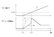
- the timing chart which shows the motor rotation speed restricted by the same control apparatus.
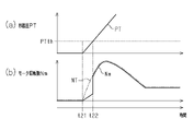
- the timing chart which shows the motor rotation speed restricted by the same control apparatus.
- the timing chart which shows the motor rotation speed restricted by the control apparatus of a modification.
- FIG. 11 is a schematic diagram showing a control device of another modification and a friction braking device that is controlled by the control device;
- FIG. 1 shows a vehicle with a control device 10 and a friction braking device 20 .
- the control device 10 controls the friction braking device 20 .
- the friction braking device 20 can generate friction braking force on the vehicle.
- a vehicle equipped with the friction braking device 20 has a braking operation member 92 .
- the brake operating member 92 can be operated by the driver of the vehicle.
- An example of the braking operation member 92 is a brake pedal.
- the vehicle may include an automatic driving control unit 80 that calculates a command value for automatically driving the vehicle.
- the automatic driving control unit 80 can transmit and receive information to and from the control device 10 .
- the friction braking device 20 includes a braking mechanism 30 corresponding to each wheel 91 of the vehicle.
- FIG. 1 illustrates one wheel 91 of the wheels 91 provided on the vehicle and a braking mechanism 30 corresponding to the wheel 91 . Illustrations of other wheels 91 and the braking mechanism 30 are omitted.
- An example of the friction braking device 20 is a hydraulic braking device.
- the hydraulic braking device can generate a frictional braking force according to the WC pressure, which is the hydraulic pressure in the wheel cylinder 31 of the braking mechanism 30 .
- the braking mechanism 30 is configured such that the higher the WC pressure, the greater the force that presses the friction material 32 against the rotating body 33 that rotates integrally with the wheel 91 .
- Each braking mechanism 30 can apply a larger braking force to the wheels 91 as the WC pressure is higher.
- the friction braking device 20 can supply brake fluid to each wheel cylinder 31 .
- the friction braking device 20 includes a master cylinder that supplies brake fluid to the wheel cylinders 31 in accordance with the operation of the braking operation member 92 .
- the friction braking device 20 includes a pressurizing mechanism 40 for pressurizing brake fluid.
- the pressurizing mechanism 40 includes an electric motor 41 and a pump 42 .
- the pump 42 is an electric pump that uses the electric motor 41 as a power source. Brake fluid discharged from a pump 42 is supplied to each wheel cylinder 31 .
- a pump 42 is a pressurization source that increases the WC pressure. The WC pressure can be increased as the amount of driving of the electric motor 41, which is the power source of the pump 42, increases.
- the friction braking device 20 which is a hydraulic braking device, can generate friction braking force by transmitting the drive amount of the electric motor 41 to the braking mechanism 30 via brake fluid.
- friction braking system 20 does not include an accumulator for storing high pressure brake fluid.
- FIG. 1 shows a brake sensor 93 and a wheel speed sensor 94 as examples of various sensors. Detection signals from various sensors are input to the control device 10 .
- the brake sensor 93 can detect the amount of operation of the braking operation member 92 .
- An example of the amount of operation of the brake operation member 92 is the pedal stroke as the amount of movement of the brake operation member 92 .
- the amount of operation of the brake operation member 92 can include a pedal effort as pressure applied to the brake operation member 92 to operate the brake operation member 92 .
- the wheel speed sensor 94 can detect the wheel speed of the wheels 91 .
- a wheel speed sensor 94 is provided for each wheel 91 .
- the vehicle speed can be calculated based on the wheel speed.
- the vehicle may be equipped with a measuring instrument for measuring noise.
- the measuring device may be installed inside the vehicle or outside the vehicle.
- the vehicle may also have a microphone mounted in the cabin. Information about sounds captured by a meter or microphone can be input to the controller 10 .
- the control device 10 will be explained.
- the control device 10 is composed of a plurality of functional units that execute various controls.
- FIG. 1 shows a motor control unit 11 and an acquisition unit 12 as examples of functional units.
- the control device 10 may have any one of the following configurations (a) to (c).
- (a) It has one or more processors that execute various processes according to a computer program.
- the processor includes a CPU and memory such as RAM and ROM.
- the memory stores program code or instructions configured to cause the CPU to perform processes.
- Memory or computer-readable media includes any available media that can be accessed by a general purpose or special purpose computer.
- (b) one or more dedicated hardware circuits for performing various processes;
- the dedicated hardware circuit is, for example, an application specific integrated circuit, that is, an ASIC (Application Specific Integrated Circuit), or an FPGA (Field Programmable Gate Array).
- a processor that executes part of various processes according to a computer program, and a dedicated hardware circuit that executes the rest of the various processes.
- the acquisition unit 12 can calculate the state quantity of the vehicle based on the detection signals from various sensors. For example, the acquisition unit 12 can calculate the operation amount of the braking operation member 92 based on the detection signal from the brake sensor 93 . That is, the acquisition unit 12 can calculate the pedal stroke, the pedal force, and the like. The acquisition unit 12 can also calculate the vehicle speed, which is the running speed of the vehicle, based on the detection signal from the wheel speed sensor 94 .
- the acquisition unit 12 can acquire a background noise level BN that is an estimated background noise level.
- the background noise here refers to noise other than the sound originating from the driving of the electric motor 41 among the noises transmitted to the driver of the vehicle.
- the background noise may also be referred to as background noise for the sound originating from driving of the electric motor 41 .
- the background noise level BN will be explained.
- the background noise level BN is a value that increases as the background noise is estimated to be louder.
- the background noise level BN is high, the background noise relative to the sound originating from the driving of the electric motor 41 is large, and it can be said that the sound originating from the driving of the electric motor 41 is less likely to be transmitted to the driver.
- the background noise level BN is low, the background noise relative to the sound derived from driving the electric motor 41 is small, and it can be said that the sound derived from driving the electric motor 41 is easily transmitted to the driver.
- the background noise is louder when the vehicle is running than when the vehicle is stopped.
- the acquisition unit 12 can calculate a larger background noise level BN as the vehicle speed increases.
- the background noise level BN may be calculated to be larger as the number of revolutions of the engine is higher.
- the acquisition unit 12 may calculate the background noise level BN to be larger as the road noise is larger. For example, when the coefficient of friction of the road surface on which the vehicle travels is high, it can be estimated that the road noise will increase. Therefore, as an example, the acquisition unit 12 can calculate a larger background noise level BN as the coefficient of friction of the road surface increases.
- the obtaining unit 12 may calculate the background noise level BN to be larger when the air conditioner is operating than when the air conditioner is not operating.
- the obtaining unit 12 may calculate the background noise level BN to be larger when sound is being output from the audio equipment than when sound is not being output from the audio equipment.
- the acquisition unit 12 may calculate the background noise level BN based on the sound pressure of the noise.
- the acquisition unit 12 may calculate the background noise level BN using sound pressure acquired from a measuring device or a microphone. Also, even if the sound pressure of the background noise is the same, when the difference between the frequency of the operating sound and the frequency of the background noise is small compared to when the difference between the frequency of the operating sound and the background noise is large. However, it is difficult for the driver to distinguish the operation sound. Therefore, it is possible to calculate the background noise level BN particularly based on the sound pressure having the same frequency as the frequency of the sound originating from driving of the electric motor 41 among the detected noises. The background noise level BN may be calculated based on the sound pressure of a predetermined frequency close to the frequency of the sound originating from driving the electric motor 41 .
- the obtaining unit 12 can obtain the target pressure PT as the target value of the pressure for pressing the friction material 32 against the rotor 33 in the braking mechanism 30 .
- the acquisition unit 12 can calculate the target pressure PT based on the pedal stroke.
- the target pressure PT is an example of an index value corresponding to the magnitude of the target value of the frictional braking force.
- index value is the target braking force as the target value of the frictional braking force.
- Other index values include the target deceleration of the vehicle, the actual braking force actually generated in the vehicle, the actual deceleration actually generated in the vehicle, and the WC pressure or the pressure generated by the pump 42 regarding the pressure of the brake fluid. servo pressure shown in FIG.
- the operation amount such as the pedal stroke and the pedal force may be used as the index value.
- the motor control unit 11 can control the electric motor 41 .
- the motor control unit 11 controls the electric motor 41 by adjusting the motor rotation speed Nm, which is the rotation speed of the electric motor 41 .
- the motor control unit 11 drives the electric motor 41 so that the motor rotation speed Nm follows the target rotation speed NT, which is the target value of the motor rotation speed Nm.
- the target rotation speed NT is the rotation speed of the electric motor 41 required to pressurize the brake fluid to the pressure for generating the frictional braking force.
- the motor control unit 11 can also execute a limiting process to limit the motor rotation speed Nm to a value smaller than the target rotation speed NT.
- the limiting process is a process for suppressing an increase in the noise generated when the electric motor 41 is driven when generation of the frictional braking force is started. Details of the restriction processing will be described later.
- FIG. 2 shows the flow of processing executed by the control device 10 .
- This processing routine is started when generation of a frictional braking force is requested.
- this processing routine is started when the brake operation member 92 is started to be operated.
- this processing routine can be started when braking is requested by the automatic driving control unit 80 .
- step S101 the control device 10 causes the acquisition unit 12 to perform acquisition processing.
- the acquisition unit 12 acquires the target pressure PT and the background noise level BN.
- the control device 10 shifts the process to step S102.
- the control device 10 causes the motor control section 11 to set the limit determination value PTth.
- the limit determination value PTth is a value for determining the magnitude of the target pressure PT, which is an index value.
- Motor control unit 11 can, for example, calculate limit determination value PTth based on background noise level BN. In this case, the motor control unit 11 calculates the limit determination value PTth smaller as the background noise level BN increases. Motor control unit 11 may calculate limit determination value PTth based on the temperature of the brake fluid. In this case, the motor control unit 11 calculates the limit determination value PTth to be smaller as the temperature of the brake fluid is lower. Also, the motor control unit 11 may calculate the limit determination value PTth based on the temperature of the friction material 32 . In this case, the motor control unit 11 calculates the limit determination value PTth to be smaller as the temperature of the friction material 32 is lower.
- values detected by a temperature sensor can be used.
- the temperature of the brake fluid and the temperature of the friction material 32 can also be calculated based on the time during which the friction braking device 20 is operated.
- control device 10 shifts the process to step S103.
- step S103 the control device 10 causes the motor control section 11 to set a limit value for the motor rotation speed Nm.
- the motor control unit 11 sets a gradient limit value that limits the speed at which the motor rotation speed Nm increases.
- the slope limit value is a value corresponding to the slope at which the motor rotation speed Nm increases.
- the motor control unit 11 can calculate the slope limit value based on the background noise level BN, for example. In this case, the larger the background noise level BN, the larger the gradient limit value calculated. That is, the greater the background noise level BN, the looser the restriction on the speed of increase.
- the motor control unit 11 may calculate the slope limit value based on the temperature of the brake fluid. In this case, the motor control unit 11 calculates a larger slope limit value as the temperature of the brake fluid is lower.
- the motor control section 11 may calculate the slope limit value based on the temperature of the friction material 32 . In this case, the motor control unit 11 calculates a larger slope limit value as the temperature of the friction material 32 is lower.
- the slope limit value can also be calculated as a value capable of suppressing a momentary increase in the pressure of the brake fluid as the motor rotation speed Nm increases when the driving of the electric motor 41 is started.
- step S104 the control device 10 causes the motor control section 11 to start restriction processing. As a result, electric motor 41 is driven while motor rotation speed Nm is limited based on the limit value set in step S103. After causing the motor control unit 11 to start the limiting process, the control device 10 shifts the process to step S105.
- step S105 the control device 10 causes the motor control section 11 to determine whether or not the target pressure PT is equal to or less than the limit determination value PTth. If target pressure PT is greater than limit determination value PTth (S105: NO), control device 10 shifts the process to step S107.
- step S107 the control device 10 causes the motor control section 11 to terminate the restriction process. As a result, the restriction on the motor rotation speed Nm is lifted. That is, the electric motor 41 is driven such that the motor rotation speed Nm follows the target rotation speed NT.
- the control device 10 causes the motor control section 11 to end the limiting process, it ends this processing routine.
- step S105 if the target pressure PT is equal to or less than the limit determination value PTth (S105: YES), the control device 10 shifts the process to step S106.
- step S106 the control device 10 causes the acquisition unit 12 to update the target pressure PT.
- the acquisition unit 12 calculates the target pressure PT at the time of executing the process of step S106 and updates the target pressure PT.
- the control device 10 shifts the process to step S105 again. That is, through the processing of steps S105 and S106, the limitation of the motor rotation speed Nm is continued until the target pressure PT exceeds the limitation determination value PTth. In other words, when the target pressure PT exceeds the limit determination value PTth, the limit on the motor rotation speed Nm is lifted.
- FIG. 3 shows the transition of the motor rotation speed Nm when the braking of the vehicle is started.
- the generation of the frictional braking force is requested from timing t11.
- the target pressure PT starts increasing from timing t11 at which the generation of the frictional braking force is required.
- the limit determination value PTth is set by requesting the generation of the frictional braking force (S102).
- a slope limit value that increases as the background noise level BN increases is set (S103), and the limit of the motor rotation speed Nm is started (S104).
- the motor rotation speed Nm is kept smaller than the target rotation speed NT, as shown in FIG. 3(b).
- the target pressure PT is increased at a constant speed after timing t11.
- the target pressure PT does not exceed the limit determination value PTth before timing t12. Therefore, during the period from timing t11 to timing t12, the motor rotation speed Nm continues to be restricted (S105, S106).
- the limit on the motor rotation speed Nm is lifted (S107). Therefore, after timing t12, motor rotation speed Nm is controlled based on target rotation speed NT.
- the period from timing t11 to timing t12 is the period for limiting the increase speed of the motor rotation speed Nm.
- control device 10 it is possible to prevent the motor rotation speed Nm from increasing during the period from when the braking of the vehicle is started until the target pressure PT exceeds the limit determination value PTth. As a result, it is possible to suppress an increase in the sound generated by the driving of the electric motor 41 during this period, and the driver is less likely to feel discomfort.
- the controller 10 calculates the limit determination value PTth smaller as the background noise level BN increases. Therefore, the greater the background noise level BN, the shorter the period until the target pressure PT exceeds the limit determination value PTth. That is, the period during which the speed of increase of the motor rotation speed Nm is restricted tends to be shortened. Therefore, when the background noise level BN is high and the driving sound of the electric motor 41 is permissible, the period for limiting the increase speed of the motor rotation speed Nm can be shortened to ensure responsiveness. As a result, it is possible to prevent the motor rotation speed Nm from becoming high at the initial stage of braking, and to shorten the period during which the speed of increase of the motor rotation speed Nm is restricted, thereby ensuring responsiveness.
- the speed at which the motor rotation speed Nm increases while the target pressure PT is equal to or less than the limit determination value PTth is limited by the slope limit value that increases as the background noise level BN increases.
- limit determination value PTth can be calculated to be smaller as the temperature of brake fluid and the temperature of friction material 32 are lower. As a result, it is possible to shorten the period during which the speed of increase of the motor rotation speed Nm is limited, thereby ensuring responsiveness. Further, in the control device 10, the lower the temperature of the brake fluid or the temperature of the friction material 32 is, the larger the gradient limit value can be, thereby loosening the limit on the increase speed of the motor rotation speed Nm. As a result, it is possible to reduce the decrease in responsiveness due to the limitation of the motor rotation speed Nm and secure the responsiveness.
- FIG. 4 shows an example in which the rate of increase of the target pressure PT is higher than in the example shown in FIG.
- the generation of the frictional braking force is requested from timing t21.
- the period until the target pressure PT exceeds the limit determination value PTth is shortened by increasing the rate of increase of the target pressure PT. That is, the period during which the increase speed of the motor rotation speed Nm is restricted is shortened.
- the limit on the motor rotation speed Nm is lifted.
- the motor rotation speed Nm is increased as the target rotation speed NT increases.
- the control device 10 when the rate of increase of the target pressure PT is large, the period for limiting the rate of increase of the motor rotation speed Nm can be shortened, and the motor rotation speed Nm can be increased early. . As a result, it is possible to drive the pump 42 at a high motor rotation speed Nm while securing a period for suppressing the increase in noise generated by driving the electric motor 41, thereby securing responsiveness. Therefore, even when sudden braking is required, it is possible to generate a frictional braking force in accordance with the request.
- the rate of increase of the target pressure PT is lower than in the example shown in FIG. 3, the period until the target pressure PT exceeds the limit determination value PTth becomes longer. That is, the period during which the speed of increase of the motor rotation speed Nm is restricted becomes longer. Therefore, when the rate of increase of the target pressure PT is low, it is possible to further suppress the increase in the noise generated by driving the electric motor 41 .
- Figures 3 and 4 show examples in which the rate of increase of the target pressure PT is constant after the start of braking.
- the target pressure PT exceeds the limit determination value PTth at an earlier time than when the target pressure PT is constant. Therefore, when the rate of increase of the target pressure PT increases, the restriction on the rate of increase of the motor rotation speed Nm is quickly lifted.
- the control device 10 it is possible to ensure responsiveness according to the target pressure PT.
- the rate of increase of the target pressure PT is reduced during braking, the period until the target pressure PT exceeds the limit determination value PTth becomes longer than when the target pressure PT is constant. Therefore, when the rate of increase of the target pressure PT is reduced, it is possible to further suppress the driver from feeling uncomfortable due to the sound originating from the electric motor 41 .
- the rate of change of the target pressure PT during operation may not be constant and may vary.
- the value of change speed may change like noise.
- the increase speed of the motor rotation speed Nm is limited based on the target pressure PT being equal to or less than the limit determination value PTth. Therefore, it is possible to control the speed of increase of the motor rotation speed Nm in response to sudden braking or gentle braking without being affected by variations in the rate of change of the target pressure PT.
- the friction braking device 20 there is one in which the braking operation member 92 is joined to the master cylinder and the pressure mechanism 40 is integrated with the master cylinder or the like.
- the pressurizing mechanism 40 is necessarily positioned near the front of the driver who operates the brake operating member 92 .
- the pressurizing mechanism 40 is then firmly connected to the vehicle body. Therefore, the sound and vibration generated by driving the electric motor 41 are more likely to be transmitted to the driver.
- the control device 10 of the present embodiment which can suppress discomfort caused by the sound originating from the electric motor 41, becomes more effective.
- the increasing speed of the motor rotation speed Nm is limited by the limiting process.
- an upper limit motor rotation speed NL is set as the upper limit of the motor rotation speed Nm.
- the motor control unit 11 limits the motor rotation speed Nm to be equal to or lower than the smaller one of the upper limit motor rotation speed NL and the target rotation speed NT during the period until the target pressure PT exceeds the limit determination value PTth. can be done. Therefore, when the motor rotation speed Nm reaches the upper limit motor rotation speed NL at timing t32 before timing t33, the motor rotation speed Nm is kept constant. After that, when the target pressure PT exceeds the limit determination value PTth at timing t33, the restriction on the motor rotation speed Nm is lifted, and the electric motor 41 is driven so that the motor rotation speed Nm follows the target rotation speed NT.
- the motor control unit 11 should set the upper limit motor rotation speed NL in addition to the slope limit value in the process of step S103 in FIG.
- the upper limit motor rotation speed NL may use a value calculated in advance by experiments or the like.
- the upper limit motor rotation speed NL may be calculated as a larger value as the background noise level BN increases.
- the upper limit motor rotation speed NL may be a variable value during braking.
- the upper limit motor rotation speed NL may be calculated by multiplying the target rotation speed NT by a value larger than "0" and smaller than "1".
- the value calculated in the process of step S102 in FIG. 2 is used as the limit determination value PTth.
- the limit determination value PTth a constant value that is calculated in advance through experiments or the like and stored in the motor control section 11 may be used. In this case, the process of step S102 in FIG. 2 may be omitted.
- the control device 10 that controls the friction braking device 20, which is a hydraulic braking device is exemplified.
- the friction braking device is not limited to the hydraulic braking device.
- the control device may control a mechanical friction braking device that generates friction braking force by mechanically transmitting the drive amount of the electric motor.
- FIG. 6 shows the control device 110 and the friction braking device 120 controlled by the control device 110 .
- the friction braking device 120 has a braking mechanism 130 .
- the braking mechanism 130 has an electric motor 141 .
- Braking mechanism 130 includes, for example, a reduction gear.
- Braking mechanism 130 includes, for example, a linear motion converting mechanism.
- the braking mechanism 130 can press the friction material 132 against the rotating body 133 according to the driving amount of the electric motor 141 transmitted by the reduction gear, the linear motion conversion mechanism, and the like.
- the control device 110 controls the friction braking device 120 and has a function of executing a limiting process for limiting the speed of increase in the rotational speed of the electric motor 141 .
- control device 110 like the control device 10 in the above embodiment, it is possible to limit the speed of increase in the rotation speed of the electric motor 141 at the initial stage of braking. More specifically, control device 110 can prevent the rotation speed of electric motor 141 from increasing during the period from when braking of the vehicle is started until the index value exceeds the limit determination value. As a result, it is possible to suppress an increase in the sound generated by driving the electric motor 141 during the period, and the driver is less likely to feel uncomfortable.
- the gradient limit value set in this case can be calculated as a value that can reduce the collision between the gears as the rotation speed increases when the electric motor 141 starts to drive.
Landscapes
- Engineering & Computer Science (AREA)
- Transportation (AREA)
- Mechanical Engineering (AREA)
- Regulating Braking Force (AREA)
- Braking Systems And Boosters (AREA)
- Valves And Accessory Devices For Braking Systems (AREA)
- Braking Arrangements (AREA)
Abstract
Description
図1は、制御装置10と摩擦制動装置20とを備える車両を示す。制御装置10は、摩擦制動装置20を制御対象とする。摩擦制動装置20は、車両に摩擦制動力を発生させることができる。摩擦制動装置20を搭載する車両は、制動操作部材92を備えている。制動操作部材92は、車両の運転者による操作が可能である。制動操作部材92の一例は、ブレーキペダルである。車両は、車両を自動走行させるための指令値を算出する自動運転制御部80を備えていてもよい。自動運転制御部80は、制御装置10との間で情報を送受信することができる。
摩擦制動装置20について説明する。摩擦制動装置20は、車両の各車輪91に対応した制動機構30を備えている。図1には、車両が備える車輪91のうち一つの車輪91と、当該車輪91に対応した制動機構30を例示している。他の車輪91および制動機構30については図示を省略している。
車両は、各種センサを備えている。図1には、各種センサの一例として、ブレーキセンサ93および車輪速センサ94を示している。各種センサからの検出信号は、制御装置10に入力される。
制御装置10について説明する。制御装置10は、各種の制御を実行する複数の機能部によって構成されている。図1には、機能部の一例として、モータ制御部11および取得部12を示している。
図2は、制御装置10が実行する処理の流れを示す。本処理ルーチンは、摩擦制動力の発生が要求されると開始される。たとえば、本処理ルーチンは、制動操作部材92が操作され始めたときに開始される。車両が自動走行されている場合には、本処理ルーチンは、自動運転制御部80によって制動が要求されたときに開始することができる。
ステップS103では、制御装置10は、モータ制御部11にモータ回転数Nmの制限値を設定させる。ここでは、モータ制御部11は、モータ回転数Nmの増加速度を制限する勾配制限値を設定する。勾配制限値は、モータ回転数Nmが増加する傾きに対応する値である。勾配制限値を小さくしてモータ回転数Nmの増加速度が制限されると、モータ回転数Nmが大きくなるまでの期間が長くされる。
ステップS104では、制御装置10は、モータ制御部11に制限処理を開始させる。この結果として、ステップS103において設定された制限値に基づいてモータ回転数Nmが制限された状態で電動モータ41が駆動される。制御装置10は、モータ制御部11に制限処理を開始させると、処理をステップS105に移行する。
本実施形態の作用および効果について説明する。
図3は、車両の制動を開始する際のモータ回転数Nmの推移を示す。図3に示す例では、タイミングt11から摩擦制動力の発生が要求されている。
本実施形態は、以下のように変更して実施することができる。本実施形態および以下の変更例は、技術的に矛盾しない範囲で互いに組み合わせて実施することができる。
図5を用いて説明する。図5に示す例では、図5の(a)に示すように、タイミングt31から摩擦制動力の発生が要求されている。タイミングt33において目標圧PTが制限判定値PTthを超えている。
Claims (4)
- 電動モータを有し、当該電動モータの駆動を開始することによって車両に摩擦制動力を発生させる摩擦制動装置に適用される制御装置であって、
前記電動モータを制御するモータ制御部と、
前記摩擦制動力の目標値の大きさに対応する指標値を取得する取得部と、を備え、
前記指標値の大きさを判定するための値を制限判定値として、
前記モータ制御部は、前記指標値が前記制限判定値以下である場合には前記電動モータの回転数の増加速度を制限し、前記指標値が前記制限判定値を超えると、当該制限を解除する
制御装置。 - 前記取得部は、前記電動モータの駆動に由来する音に対する暗騒音の大きさを推定した暗騒音レベルを取得し、
前記モータ制御部は、前記暗騒音レベルが大きいほど前記制限判定値を小さく設定する
請求項1に記載の制御装置。 - 前記取得部は、前記電動モータの駆動に由来する音に対する暗騒音の大きさを推定した暗騒音レベルを取得し、
前記モータ制御部は、前記指標値が前記制限判定値以下である場合には、前記暗騒音レベルが小さいほど前記増加速度を小さくする
請求項1または2に記載の制御装置。 - 前記取得部は、前記車両の車速が大きいほど前記暗騒音レベルを大きくする
請求項2または3に記載の制御装置。
Priority Applications (3)
| Application Number | Priority Date | Filing Date | Title |
|---|---|---|---|
| DE112022001271.4T DE112022001271T5 (de) | 2021-02-26 | 2022-02-25 | Steuerungsvorrichtung |
| CN202280016853.7A CN116940490A (zh) | 2021-02-26 | 2022-02-25 | 控制装置 |
| US18/264,103 US20240092321A1 (en) | 2021-02-26 | 2022-02-25 | Control device |
Applications Claiming Priority (2)
| Application Number | Priority Date | Filing Date | Title |
|---|---|---|---|
| JP2021-031060 | 2021-02-26 | ||
| JP2021031060A JP7484771B2 (ja) | 2021-02-26 | 2021-02-26 | 制御装置 |
Publications (1)
| Publication Number | Publication Date |
|---|---|
| WO2022181780A1 true WO2022181780A1 (ja) | 2022-09-01 |
Family
ID=83047551
Family Applications (1)
| Application Number | Title | Priority Date | Filing Date |
|---|---|---|---|
| PCT/JP2022/007977 Ceased WO2022181780A1 (ja) | 2021-02-26 | 2022-02-25 | 制御装置 |
Country Status (5)
| Country | Link |
|---|---|
| US (1) | US20240092321A1 (ja) |
| JP (1) | JP7484771B2 (ja) |
| CN (1) | CN116940490A (ja) |
| DE (1) | DE112022001271T5 (ja) |
| WO (1) | WO2022181780A1 (ja) |
Citations (2)
| Publication number | Priority date | Publication date | Assignee | Title |
|---|---|---|---|---|
| JPH08127331A (ja) * | 1994-11-01 | 1996-05-21 | Toyota Motor Corp | 液圧ブレーキ装置 |
| US20100033009A1 (en) * | 2005-09-30 | 2010-02-11 | Lucas Automotive Gmbh | Method and Device for Tightening a Hydraulic Parking Brake |
Family Cites Families (7)
| Publication number | Priority date | Publication date | Assignee | Title |
|---|---|---|---|---|
| JP2004286054A (ja) * | 2003-03-19 | 2004-10-14 | Advics:Kk | 車両用制動装置 |
| JP4924100B2 (ja) * | 2007-03-01 | 2012-04-25 | 株式会社アドヴィックス | 車両の電動モータ出力制御装置 |
| EP2463165B1 (en) * | 2009-08-07 | 2015-03-18 | Toyota Jidosha Kabushiki Kaisha | Brake control system, and brake control method |
| JP5454893B2 (ja) * | 2009-09-28 | 2014-03-26 | 株式会社アドヴィックス | 制動制御装置と当該制動制御装置に用いられるモータ回転数演算方法 |
| JP6247186B2 (ja) * | 2014-09-30 | 2017-12-13 | オートリブ日信ブレーキシステムジャパン株式会社 | 車両用制御装置 |
| JP6648739B2 (ja) * | 2017-03-31 | 2020-02-14 | 株式会社アドヴィックス | 車両の制動制御装置 |
| JP7098907B2 (ja) | 2017-10-17 | 2022-07-12 | 株式会社アドヴィックス | 車両の制動制御装置 |
-
2021
- 2021-02-26 JP JP2021031060A patent/JP7484771B2/ja active Active
-
2022
- 2022-02-25 DE DE112022001271.4T patent/DE112022001271T5/de active Pending
- 2022-02-25 US US18/264,103 patent/US20240092321A1/en active Pending
- 2022-02-25 WO PCT/JP2022/007977 patent/WO2022181780A1/ja not_active Ceased
- 2022-02-25 CN CN202280016853.7A patent/CN116940490A/zh active Pending
Patent Citations (2)
| Publication number | Priority date | Publication date | Assignee | Title |
|---|---|---|---|---|
| JPH08127331A (ja) * | 1994-11-01 | 1996-05-21 | Toyota Motor Corp | 液圧ブレーキ装置 |
| US20100033009A1 (en) * | 2005-09-30 | 2010-02-11 | Lucas Automotive Gmbh | Method and Device for Tightening a Hydraulic Parking Brake |
Also Published As
| Publication number | Publication date |
|---|---|
| JP2022131871A (ja) | 2022-09-07 |
| JP7484771B2 (ja) | 2024-05-16 |
| DE112022001271T5 (de) | 2023-12-14 |
| US20240092321A1 (en) | 2024-03-21 |
| CN116940490A (zh) | 2023-10-24 |
Similar Documents
| Publication | Publication Date | Title |
|---|---|---|
| JP4835471B2 (ja) | 車両の制動装置 | |
| JP5604531B2 (ja) | ブレーキブースタおよびブレーキブースタを作動させるための方法および装置 | |
| CN101519064B (zh) | 制动装置 | |
| JP5324711B2 (ja) | 車両のブレーキ力増幅式ブレーキ装置の制御方法および装置 | |
| KR102691685B1 (ko) | 차량 제어 장치, 차량 제어 방법 및 차량 제어 시스템 | |
| US20110130935A1 (en) | Methods and systems for brake pedal tuning and braking control in vehicles | |
| JP4743961B2 (ja) | 自動車用ブレーキ装置の制御装置と方法 | |
| CN104159798B (zh) | 用于运行机动车的制动力放大器的方法和用于机动车的制动力放大器的控制装置 | |
| JP2022131871A (ja) | 制御装置 | |
| CN110139787B (zh) | 用于操作车辆制动系统的机电式制动助力器的控制设备和方法 | |
| WO2023276962A1 (ja) | 制御装置 | |
| JP7509705B2 (ja) | 車両の振動低減装置 | |
| JP2002127889A (ja) | 車両用ブレーキ装置 | |
| JP2021091262A (ja) | 車両の制御装置 | |
| JP4492340B2 (ja) | 車両振動抑制装置 | |
| WO2013094593A1 (ja) | ブレーキ制御装置 | |
| US20200122705A1 (en) | Method for operating a brake system of a motor vehicle, brake system, motor vehicle | |
| JP2020070779A (ja) | 車両制御装置 | |
| JP4830549B2 (ja) | 車両用制動装置の摩耗矯正装置 | |
| JP2002104169A (ja) | 車両用ブレーキ装置 | |
| JP5649797B2 (ja) | 車両用制動制御装置 | |
| WO2026048929A1 (ja) | 制動制御装置 | |
| JP2000016278A (ja) | 車両の制動力制御装置 | |
| JP2016175445A (ja) | 車両用ブレーキ装置 | |
| JP2015178349A (ja) | ブレーキ制御装置 |
Legal Events
| Date | Code | Title | Description |
|---|---|---|---|
| 121 | Ep: the epo has been informed by wipo that ep was designated in this application |
Ref document number: 22759814 Country of ref document: EP Kind code of ref document: A1 |
|
| WWE | Wipo information: entry into national phase |
Ref document number: 18264103 Country of ref document: US |
|
| WWE | Wipo information: entry into national phase |
Ref document number: 202280016853.7 Country of ref document: CN |
|
| WWE | Wipo information: entry into national phase |
Ref document number: 112022001271 Country of ref document: DE |
|
| 122 | Ep: pct application non-entry in european phase |
Ref document number: 22759814 Country of ref document: EP Kind code of ref document: A1 |