WO2022181529A1 - Matériau d'emballage stratifié métallique, récipient moulé et emballage - Google Patents
Matériau d'emballage stratifié métallique, récipient moulé et emballage Download PDFInfo
- Publication number
- WO2022181529A1 WO2022181529A1 PCT/JP2022/006897 JP2022006897W WO2022181529A1 WO 2022181529 A1 WO2022181529 A1 WO 2022181529A1 JP 2022006897 W JP2022006897 W JP 2022006897W WO 2022181529 A1 WO2022181529 A1 WO 2022181529A1
- Authority
- WO
- WIPO (PCT)
- Prior art keywords
- layer
- biomass
- derived
- container
- packaging material
- Prior art date
Links
- 239000005022 packaging material Substances 0.000 title claims abstract description 138
- 229910052751 metal Inorganic materials 0.000 title claims abstract description 83
- 239000002184 metal Substances 0.000 title claims abstract description 83
- 238000004806 packaging method and process Methods 0.000 title claims description 13
- 239000010410 layer Substances 0.000 claims abstract description 185
- 239000002028 Biomass Substances 0.000 claims abstract description 153
- 239000011241 protective layer Substances 0.000 claims abstract description 119
- 229920005989 resin Polymers 0.000 claims abstract description 113
- 239000011347 resin Substances 0.000 claims abstract description 113
- 239000011888 foil Substances 0.000 claims abstract description 66
- 230000004888 barrier function Effects 0.000 claims abstract description 52
- 229920003002 synthetic resin Polymers 0.000 claims abstract description 39
- 239000000057 synthetic resin Substances 0.000 claims abstract description 39
- 238000007789 sealing Methods 0.000 claims description 69
- 239000012793 heat-sealing layer Substances 0.000 claims description 61
- -1 polyethylene Polymers 0.000 claims description 49
- 229920000098 polyolefin Polymers 0.000 claims description 41
- 229920000728 polyester Polymers 0.000 claims description 38
- 239000004698 Polyethylene Substances 0.000 claims description 16
- 229920000573 polyethylene Polymers 0.000 claims description 16
- 229920005676 ethylene-propylene block copolymer Polymers 0.000 claims description 13
- 229920000139 polyethylene terephthalate Polymers 0.000 claims description 12
- 239000005020 polyethylene terephthalate Substances 0.000 claims description 12
- 229920005674 ethylene-propylene random copolymer Polymers 0.000 claims description 11
- 230000002093 peripheral effect Effects 0.000 claims description 6
- 238000003825 pressing Methods 0.000 claims description 4
- 239000012790 adhesive layer Substances 0.000 abstract description 58
- OKTJSMMVPCPJKN-UHFFFAOYSA-N Carbon Chemical compound [C] OKTJSMMVPCPJKN-UHFFFAOYSA-N 0.000 abstract description 14
- 229910052799 carbon Inorganic materials 0.000 abstract description 14
- QVGXLLKOCUKJST-UHFFFAOYSA-N atomic oxygen Chemical compound [O] QVGXLLKOCUKJST-UHFFFAOYSA-N 0.000 abstract description 3
- 230000000694 effects Effects 0.000 abstract description 3
- 229910052760 oxygen Inorganic materials 0.000 abstract description 3
- 239000001301 oxygen Substances 0.000 abstract description 3
- 229910052782 aluminium Inorganic materials 0.000 description 45
- XAGFODPZIPBFFR-UHFFFAOYSA-N aluminium Chemical compound [Al] XAGFODPZIPBFFR-UHFFFAOYSA-N 0.000 description 45
- 239000000853 adhesive Substances 0.000 description 31
- 230000001070 adhesive effect Effects 0.000 description 31
- LYCAIKOWRPUZTN-UHFFFAOYSA-N Ethylene glycol Chemical compound OCCO LYCAIKOWRPUZTN-UHFFFAOYSA-N 0.000 description 21
- 239000002994 raw material Substances 0.000 description 19
- 239000002356 single layer Substances 0.000 description 19
- 229920002635 polyurethane Polymers 0.000 description 18
- 239000004814 polyurethane Substances 0.000 description 18
- 230000032798 delamination Effects 0.000 description 17
- 238000000034 method Methods 0.000 description 17
- 239000000463 material Substances 0.000 description 16
- 238000000465 moulding Methods 0.000 description 16
- 239000004743 Polypropylene Substances 0.000 description 15
- KKEYFWRCBNTPAC-UHFFFAOYSA-N Terephthalic acid Chemical compound OC(=O)C1=CC=C(C(O)=O)C=C1 KKEYFWRCBNTPAC-UHFFFAOYSA-N 0.000 description 14
- 239000002648 laminated material Substances 0.000 description 14
- 238000004519 manufacturing process Methods 0.000 description 13
- 229920001155 polypropylene Polymers 0.000 description 12
- 238000006386 neutralization reaction Methods 0.000 description 11
- XLYOFNOQVPJJNP-UHFFFAOYSA-N water Chemical compound O XLYOFNOQVPJJNP-UHFFFAOYSA-N 0.000 description 11
- 150000001991 dicarboxylic acids Chemical class 0.000 description 10
- 239000004952 Polyamide Substances 0.000 description 9
- 230000000704 physical effect Effects 0.000 description 9
- 229920002647 polyamide Polymers 0.000 description 9
- 239000004677 Nylon Substances 0.000 description 8
- WNLRTRBMVRJNCN-UHFFFAOYSA-N adipic acid Chemical compound OC(=O)CCCCC(O)=O WNLRTRBMVRJNCN-UHFFFAOYSA-N 0.000 description 8
- QQVIHTHCMHWDBS-UHFFFAOYSA-N isophthalic acid Chemical compound OC(=O)C1=CC=CC(C(O)=O)=C1 QQVIHTHCMHWDBS-UHFFFAOYSA-N 0.000 description 8
- 150000002596 lactones Chemical class 0.000 description 8
- 238000003475 lamination Methods 0.000 description 8
- 229920001778 nylon Polymers 0.000 description 8
- CXMXRPHRNRROMY-UHFFFAOYSA-N sebacic acid Chemical compound OC(=O)CCCCCCCCC(O)=O CXMXRPHRNRROMY-UHFFFAOYSA-N 0.000 description 8
- 239000007788 liquid Substances 0.000 description 7
- 239000000047 product Substances 0.000 description 7
- 239000000126 substance Substances 0.000 description 7
- DNIAPMSPPWPWGF-UHFFFAOYSA-N Propylene glycol Chemical compound CC(O)CO DNIAPMSPPWPWGF-UHFFFAOYSA-N 0.000 description 6
- IISBACLAFKSPIT-UHFFFAOYSA-N bisphenol A Chemical compound C=1C=C(O)C=CC=1C(C)(C)C1=CC=C(O)C=C1 IISBACLAFKSPIT-UHFFFAOYSA-N 0.000 description 6
- KRKNYBCHXYNGOX-UHFFFAOYSA-N citric acid Chemical compound OC(=O)CC(O)(C(O)=O)CC(O)=O KRKNYBCHXYNGOX-UHFFFAOYSA-N 0.000 description 6
- 150000004985 diamines Chemical class 0.000 description 6
- MTHSVFCYNBDYFN-UHFFFAOYSA-N diethylene glycol Chemical compound OCCOCCO MTHSVFCYNBDYFN-UHFFFAOYSA-N 0.000 description 6
- 229920000642 polymer Polymers 0.000 description 6
- 230000008569 process Effects 0.000 description 6
- 150000001336 alkenes Chemical class 0.000 description 5
- 238000006243 chemical reaction Methods 0.000 description 5
- 229920001971 elastomer Polymers 0.000 description 5
- 239000000806 elastomer Substances 0.000 description 5
- 238000005304 joining Methods 0.000 description 5
- VZCYOOQTPOCHFL-UHFFFAOYSA-N trans-butenedioic acid Natural products OC(=O)C=CC(O)=O VZCYOOQTPOCHFL-UHFFFAOYSA-N 0.000 description 5
- 239000001993 wax Substances 0.000 description 5
- FJKROLUGYXJWQN-UHFFFAOYSA-N 4-hydroxybenzoic acid Chemical compound OC(=O)C1=CC=C(O)C=C1 FJKROLUGYXJWQN-UHFFFAOYSA-N 0.000 description 4
- OZJPLYNZGCXSJM-UHFFFAOYSA-N 5-valerolactone Chemical compound O=C1CCCCO1 OZJPLYNZGCXSJM-UHFFFAOYSA-N 0.000 description 4
- RSWGJHLUYNHPMX-UHFFFAOYSA-N Abietic-Saeure Natural products C12CCC(C(C)C)=CC2=CCC2C1(C)CCCC2(C)C(O)=O RSWGJHLUYNHPMX-UHFFFAOYSA-N 0.000 description 4
- CURLTUGMZLYLDI-UHFFFAOYSA-N Carbon dioxide Chemical compound O=C=O CURLTUGMZLYLDI-UHFFFAOYSA-N 0.000 description 4
- VYZAMTAEIAYCRO-UHFFFAOYSA-N Chromium Chemical compound [Cr] VYZAMTAEIAYCRO-UHFFFAOYSA-N 0.000 description 4
- VZCYOOQTPOCHFL-OWOJBTEDSA-N Fumaric acid Chemical compound OC(=O)\C=C\C(O)=O VZCYOOQTPOCHFL-OWOJBTEDSA-N 0.000 description 4
- PEDCQBHIVMGVHV-UHFFFAOYSA-N Glycerine Chemical compound OCC(O)CO PEDCQBHIVMGVHV-UHFFFAOYSA-N 0.000 description 4
- URLKBWYHVLBVBO-UHFFFAOYSA-N Para-Xylene Chemical group CC1=CC=C(C)C=C1 URLKBWYHVLBVBO-UHFFFAOYSA-N 0.000 description 4
- NBIIXXVUZAFLBC-UHFFFAOYSA-N Phosphoric acid Chemical compound OP(O)(O)=O NBIIXXVUZAFLBC-UHFFFAOYSA-N 0.000 description 4
- KHPCPRHQVVSZAH-HUOMCSJISA-N Rosin Natural products O(C/C=C/c1ccccc1)[C@H]1[C@H](O)[C@@H](O)[C@@H](O)[C@@H](CO)O1 KHPCPRHQVVSZAH-HUOMCSJISA-N 0.000 description 4
- 239000002253 acid Substances 0.000 description 4
- 150000007513 acids Chemical class 0.000 description 4
- 239000001361 adipic acid Substances 0.000 description 4
- 235000011037 adipic acid Nutrition 0.000 description 4
- 239000011230 binding agent Substances 0.000 description 4
- BVKZGUZCCUSVTD-UHFFFAOYSA-N carbonic acid Chemical class OC(O)=O BVKZGUZCCUSVTD-UHFFFAOYSA-N 0.000 description 4
- 239000007795 chemical reaction product Substances 0.000 description 4
- 229910052804 chromium Inorganic materials 0.000 description 4
- 239000011651 chromium Substances 0.000 description 4
- 150000001875 compounds Chemical class 0.000 description 4
- 230000007797 corrosion Effects 0.000 description 4
- 238000005260 corrosion Methods 0.000 description 4
- 238000009820 dry lamination Methods 0.000 description 4
- JBKVHLHDHHXQEQ-UHFFFAOYSA-N epsilon-caprolactam Chemical compound O=C1CCCCCN1 JBKVHLHDHHXQEQ-UHFFFAOYSA-N 0.000 description 4
- 238000001125 extrusion Methods 0.000 description 4
- NAQMVNRVTILPCV-UHFFFAOYSA-N hexane-1,6-diamine Chemical compound NCCCCCCN NAQMVNRVTILPCV-UHFFFAOYSA-N 0.000 description 4
- 238000002844 melting Methods 0.000 description 4
- 230000008018 melting Effects 0.000 description 4
- 239000000203 mixture Substances 0.000 description 4
- BDJRBEYXGGNYIS-UHFFFAOYSA-N nonanedioic acid Chemical compound OC(=O)CCCCCCCC(O)=O BDJRBEYXGGNYIS-UHFFFAOYSA-N 0.000 description 4
- 229920005862 polyol Polymers 0.000 description 4
- 150000003077 polyols Chemical class 0.000 description 4
- 229920005629 polypropylene homopolymer Polymers 0.000 description 4
- CYIDZMCFTVVTJO-UHFFFAOYSA-N pyromellitic acid Chemical compound OC(=O)C1=CC(C(O)=O)=C(C(O)=O)C=C1C(O)=O CYIDZMCFTVVTJO-UHFFFAOYSA-N 0.000 description 4
- KHPCPRHQVVSZAH-UHFFFAOYSA-N trans-cinnamyl beta-D-glucopyranoside Natural products OC1C(O)C(O)C(CO)OC1OCC=CC1=CC=CC=C1 KHPCPRHQVVSZAH-UHFFFAOYSA-N 0.000 description 4
- ARCGXLSVLAOJQL-UHFFFAOYSA-N trimellitic acid Chemical compound OC(=O)C1=CC=C(C(O)=O)C(C(O)=O)=C1 ARCGXLSVLAOJQL-UHFFFAOYSA-N 0.000 description 4
- 238000012795 verification Methods 0.000 description 4
- OFOBLEOULBTSOW-UHFFFAOYSA-N Propanedioic acid Natural products OC(=O)CC(O)=O OFOBLEOULBTSOW-UHFFFAOYSA-N 0.000 description 3
- VYPSYNLAJGMNEJ-UHFFFAOYSA-N Silicium dioxide Chemical compound O=[Si]=O VYPSYNLAJGMNEJ-UHFFFAOYSA-N 0.000 description 3
- 230000007613 environmental effect Effects 0.000 description 3
- 235000013305 food Nutrition 0.000 description 3
- 238000007756 gravure coating Methods 0.000 description 3
- 239000000976 ink Substances 0.000 description 3
- VZCYOOQTPOCHFL-UPHRSURJSA-N maleic acid Chemical compound OC(=O)\C=C/C(O)=O VZCYOOQTPOCHFL-UPHRSURJSA-N 0.000 description 3
- 239000011976 maleic acid Substances 0.000 description 3
- 239000005011 phenolic resin Substances 0.000 description 3
- 239000000049 pigment Substances 0.000 description 3
- 229920005749 polyurethane resin Polymers 0.000 description 3
- 238000012545 processing Methods 0.000 description 3
- 229920002803 thermoplastic polyurethane Polymers 0.000 description 3
- 239000002699 waste material Substances 0.000 description 3
- 230000037303 wrinkles Effects 0.000 description 3
- BJEPYKJPYRNKOW-REOHCLBHSA-N (S)-malic acid Chemical compound OC(=O)[C@@H](O)CC(O)=O BJEPYKJPYRNKOW-REOHCLBHSA-N 0.000 description 2
- WMYINDVYGQKYMI-UHFFFAOYSA-N 2-[2,2-bis(hydroxymethyl)butoxymethyl]-2-ethylpropane-1,3-diol Chemical compound CCC(CO)(CO)COCC(CC)(CO)CO WMYINDVYGQKYMI-UHFFFAOYSA-N 0.000 description 2
- NMYFVWYGKGVPIW-UHFFFAOYSA-N 3,7-dioxabicyclo[7.2.2]trideca-1(11),9,12-triene-2,8-dione Chemical compound O=C1OCCCOC(=O)C2=CC=C1C=C2 NMYFVWYGKGVPIW-UHFFFAOYSA-N 0.000 description 2
- QLIQIXIBZLTPGQ-UHFFFAOYSA-N 4-(2-hydroxyethoxy)benzoic acid Chemical compound OCCOC1=CC=C(C(O)=O)C=C1 QLIQIXIBZLTPGQ-UHFFFAOYSA-N 0.000 description 2
- 229940090248 4-hydroxybenzoic acid Drugs 0.000 description 2
- 229920000178 Acrylic resin Chemical class 0.000 description 2
- 239000004925 Acrylic resin Chemical class 0.000 description 2
- 229910000838 Al alloy Inorganic materials 0.000 description 2
- 229930185605 Bisphenol Natural products 0.000 description 2
- FEWJPZIEWOKRBE-JCYAYHJZSA-N Dextrotartaric acid Chemical compound OC(=O)[C@H](O)[C@@H](O)C(O)=O FEWJPZIEWOKRBE-JCYAYHJZSA-N 0.000 description 2
- LFQSCWFLJHTTHZ-UHFFFAOYSA-N EtOH Substances CCO LFQSCWFLJHTTHZ-UHFFFAOYSA-N 0.000 description 2
- YCKRFDGAMUMZLT-UHFFFAOYSA-N Fluorine atom Chemical compound [F] YCKRFDGAMUMZLT-UHFFFAOYSA-N 0.000 description 2
- JHWNWJKBPDFINM-UHFFFAOYSA-N Laurolactam Chemical compound O=C1CCCCCCCCCCCN1 JHWNWJKBPDFINM-UHFFFAOYSA-N 0.000 description 2
- 229920000571 Nylon 11 Polymers 0.000 description 2
- 229920000299 Nylon 12 Polymers 0.000 description 2
- 229920002292 Nylon 6 Polymers 0.000 description 2
- 229920002302 Nylon 6,6 Polymers 0.000 description 2
- 239000002202 Polyethylene glycol Substances 0.000 description 2
- FEWJPZIEWOKRBE-UHFFFAOYSA-N Tartaric acid Natural products [H+].[H+].[O-]C(=O)C(O)C(O)C([O-])=O FEWJPZIEWOKRBE-UHFFFAOYSA-N 0.000 description 2
- 229920002433 Vinyl chloride-vinyl acetate copolymer Polymers 0.000 description 2
- ORLQHILJRHBSAY-UHFFFAOYSA-N [1-(hydroxymethyl)cyclohexyl]methanol Chemical compound OCC1(CO)CCCCC1 ORLQHILJRHBSAY-UHFFFAOYSA-N 0.000 description 2
- 239000004840 adhesive resin Substances 0.000 description 2
- 229920006223 adhesive resin Polymers 0.000 description 2
- 125000002723 alicyclic group Chemical group 0.000 description 2
- 125000001931 aliphatic group Chemical group 0.000 description 2
- BJEPYKJPYRNKOW-UHFFFAOYSA-N alpha-hydroxysuccinic acid Natural products OC(=O)C(O)CC(O)=O BJEPYKJPYRNKOW-UHFFFAOYSA-N 0.000 description 2
- 229910000147 aluminium phosphate Inorganic materials 0.000 description 2
- QFNNDGVVMCZKEY-UHFFFAOYSA-N azacyclododecan-2-one Chemical compound O=C1CCCCCCCCCCN1 QFNNDGVVMCZKEY-UHFFFAOYSA-N 0.000 description 2
- AYJRCSIUFZENHW-DEQYMQKBSA-L barium(2+);oxomethanediolate Chemical compound [Ba+2].[O-][14C]([O-])=O AYJRCSIUFZENHW-DEQYMQKBSA-L 0.000 description 2
- GSCLMSFRWBPUSK-UHFFFAOYSA-N beta-Butyrolactone Chemical compound CC1CC(=O)O1 GSCLMSFRWBPUSK-UHFFFAOYSA-N 0.000 description 2
- CDQSJQSWAWPGKG-UHFFFAOYSA-N butane-1,1-diol Chemical compound CCCC(O)O CDQSJQSWAWPGKG-UHFFFAOYSA-N 0.000 description 2
- 125000004432 carbon atom Chemical group C* 0.000 description 2
- 239000001569 carbon dioxide Substances 0.000 description 2
- 229910002092 carbon dioxide Inorganic materials 0.000 description 2
- 235000015165 citric acid Nutrition 0.000 description 2
- 230000000052 comparative effect Effects 0.000 description 2
- 238000006482 condensation reaction Methods 0.000 description 2
- QYQADNCHXSEGJT-UHFFFAOYSA-N cyclohexane-1,1-dicarboxylate;hydron Chemical compound OC(=O)C1(C(O)=O)CCCCC1 QYQADNCHXSEGJT-UHFFFAOYSA-N 0.000 description 2
- 229940105990 diglycerin Drugs 0.000 description 2
- GPLRAVKSCUXZTP-UHFFFAOYSA-N diglycerol Chemical compound OCC(O)COCC(O)CO GPLRAVKSCUXZTP-UHFFFAOYSA-N 0.000 description 2
- 239000003814 drug Substances 0.000 description 2
- 150000004673 fluoride salts Chemical class 0.000 description 2
- 229910052731 fluorine Inorganic materials 0.000 description 2
- 239000011737 fluorine Substances 0.000 description 2
- 239000001530 fumaric acid Substances 0.000 description 2
- ANSXAPJVJOKRDJ-UHFFFAOYSA-N furo[3,4-f][2]benzofuran-1,3,5,7-tetrone Chemical compound C1=C2C(=O)OC(=O)C2=CC2=C1C(=O)OC2=O ANSXAPJVJOKRDJ-UHFFFAOYSA-N 0.000 description 2
- 239000007789 gas Substances 0.000 description 2
- 235000011187 glycerol Nutrition 0.000 description 2
- 229920000092 linear low density polyethylene Polymers 0.000 description 2
- 239000004707 linear low-density polyethylene Substances 0.000 description 2
- 230000007774 longterm Effects 0.000 description 2
- 230000014759 maintenance of location Effects 0.000 description 2
- FPYJFEHAWHCUMM-UHFFFAOYSA-N maleic anhydride Chemical compound O=C1OC(=O)C=C1 FPYJFEHAWHCUMM-UHFFFAOYSA-N 0.000 description 2
- 239000001630 malic acid Substances 0.000 description 2
- 235000011090 malic acid Nutrition 0.000 description 2
- 239000000178 monomer Substances 0.000 description 2
- KYTZHLUVELPASH-UHFFFAOYSA-N naphthalene-1,2-dicarboxylic acid Chemical compound C1=CC=CC2=C(C(O)=O)C(C(=O)O)=CC=C21 KYTZHLUVELPASH-UHFFFAOYSA-N 0.000 description 2
- SLCVBVWXLSEKPL-UHFFFAOYSA-N neopentyl glycol Chemical compound OCC(C)(C)CO SLCVBVWXLSEKPL-UHFFFAOYSA-N 0.000 description 2
- WXZMFSXDPGVJKK-UHFFFAOYSA-N pentaerythritol Chemical compound OCC(CO)(CO)CO WXZMFSXDPGVJKK-UHFFFAOYSA-N 0.000 description 2
- 229920001568 phenolic resin Polymers 0.000 description 2
- 239000004417 polycarbonate Substances 0.000 description 2
- 229920000515 polycarbonate Polymers 0.000 description 2
- 238000006068 polycondensation reaction Methods 0.000 description 2
- 229920001223 polyethylene glycol Polymers 0.000 description 2
- 238000007639 printing Methods 0.000 description 2
- 238000004080 punching Methods 0.000 description 2
- 229920005604 random copolymer Polymers 0.000 description 2
- 238000004064 recycling Methods 0.000 description 2
- 230000003014 reinforcing effect Effects 0.000 description 2
- 239000007787 solid Substances 0.000 description 2
- 238000003860 storage Methods 0.000 description 2
- 239000011975 tartaric acid Substances 0.000 description 2
- 235000002906 tartaric acid Nutrition 0.000 description 2
- 150000000000 tetracarboxylic acids Chemical class 0.000 description 2
- SRPWOOOHEPICQU-UHFFFAOYSA-N trimellitic anhydride Chemical compound OC(=O)C1=CC=C2C(=O)OC(=O)C2=C1 SRPWOOOHEPICQU-UHFFFAOYSA-N 0.000 description 2
- QXJQHYBHAIHNGG-UHFFFAOYSA-N trimethylolethane Chemical compound OCC(C)(CO)CO QXJQHYBHAIHNGG-UHFFFAOYSA-N 0.000 description 2
- PAPBSGBWRJIAAV-UHFFFAOYSA-N ε-Caprolactone Chemical compound O=C1CCCCCO1 PAPBSGBWRJIAAV-UHFFFAOYSA-N 0.000 description 2
- 229910002012 Aerosil® Inorganic materials 0.000 description 1
- 229920002799 BoPET Polymers 0.000 description 1
- 240000002791 Brassica napus Species 0.000 description 1
- 235000004977 Brassica sinapistrum Nutrition 0.000 description 1
- 229920001661 Chitosan Chemical class 0.000 description 1
- RYGMFSIKBFXOCR-UHFFFAOYSA-N Copper Chemical compound [Cu] RYGMFSIKBFXOCR-UHFFFAOYSA-N 0.000 description 1
- 239000005977 Ethylene Substances 0.000 description 1
- XEEYBQQBJWHFJM-UHFFFAOYSA-N Iron Chemical compound [Fe] XEEYBQQBJWHFJM-UHFFFAOYSA-N 0.000 description 1
- 229920000426 Microplastic Polymers 0.000 description 1
- 244000294411 Mirabilis expansa Species 0.000 description 1
- 235000015429 Mirabilis expansa Nutrition 0.000 description 1
- PXHVJJICTQNCMI-UHFFFAOYSA-N Nickel Chemical compound [Ni] PXHVJJICTQNCMI-UHFFFAOYSA-N 0.000 description 1
- 239000000020 Nitrocellulose Substances 0.000 description 1
- 239000004721 Polyphenylene oxide Substances 0.000 description 1
- 239000004793 Polystyrene Substances 0.000 description 1
- 240000000111 Saccharum officinarum Species 0.000 description 1
- 235000007201 Saccharum officinarum Nutrition 0.000 description 1
- 229920001800 Shellac Polymers 0.000 description 1
- 229920002125 Sokalan® Polymers 0.000 description 1
- 229920002472 Starch Polymers 0.000 description 1
- 229910000831 Steel Inorganic materials 0.000 description 1
- GWEVSGVZZGPLCZ-UHFFFAOYSA-N Titan oxide Chemical compound O=[Ti]=O GWEVSGVZZGPLCZ-UHFFFAOYSA-N 0.000 description 1
- 240000008042 Zea mays Species 0.000 description 1
- 235000005824 Zea mays ssp. parviglumis Nutrition 0.000 description 1
- 235000002017 Zea mays subsp mays Nutrition 0.000 description 1
- XLOMVQKBTHCTTD-UHFFFAOYSA-N Zinc monoxide Chemical compound [Zn]=O XLOMVQKBTHCTTD-UHFFFAOYSA-N 0.000 description 1
- 230000032683 aging Effects 0.000 description 1
- 150000001298 alcohols Chemical class 0.000 description 1
- PNEYBMLMFCGWSK-UHFFFAOYSA-N aluminium oxide Inorganic materials [O-2].[O-2].[O-2].[Al+3].[Al+3] PNEYBMLMFCGWSK-UHFFFAOYSA-N 0.000 description 1
- 150000001408 amides Chemical class 0.000 description 1
- 230000005540 biological transmission Effects 0.000 description 1
- 230000000903 blocking effect Effects 0.000 description 1
- 235000014121 butter Nutrition 0.000 description 1
- 239000000378 calcium silicate Substances 0.000 description 1
- 229910052918 calcium silicate Inorganic materials 0.000 description 1
- OYACROKNLOSFPA-UHFFFAOYSA-N calcium;dioxido(oxo)silane Chemical compound [Ca+2].[O-][Si]([O-])=O OYACROKNLOSFPA-UHFFFAOYSA-N 0.000 description 1
- 235000014633 carbohydrates Nutrition 0.000 description 1
- 150000001720 carbohydrates Chemical class 0.000 description 1
- 239000006229 carbon black Substances 0.000 description 1
- 229920002301 cellulose acetate Polymers 0.000 description 1
- 230000008859 change Effects 0.000 description 1
- 235000013351 cheese Nutrition 0.000 description 1
- 239000003795 chemical substances by application Substances 0.000 description 1
- JYWJULGYGOLCGW-UHFFFAOYSA-N chloromethyl chloroformate Chemical compound ClCOC(Cl)=O JYWJULGYGOLCGW-UHFFFAOYSA-N 0.000 description 1
- KRVSOGSZCMJSLX-UHFFFAOYSA-L chromic acid Substances O[Cr](O)(=O)=O KRVSOGSZCMJSLX-UHFFFAOYSA-L 0.000 description 1
- BFGKITSFLPAWGI-UHFFFAOYSA-N chromium(3+) Chemical class [Cr+3] BFGKITSFLPAWGI-UHFFFAOYSA-N 0.000 description 1
- 239000011248 coating agent Substances 0.000 description 1
- 238000000576 coating method Methods 0.000 description 1
- 238000004040 coloring Methods 0.000 description 1
- 238000010276 construction Methods 0.000 description 1
- 239000011889 copper foil Substances 0.000 description 1
- 235000005822 corn Nutrition 0.000 description 1
- 239000006071 cream Substances 0.000 description 1
- 235000021438 curry Nutrition 0.000 description 1
- 235000015071 dressings Nutrition 0.000 description 1
- 238000001035 drying Methods 0.000 description 1
- 238000005265 energy consumption Methods 0.000 description 1
- 229920006332 epoxy adhesive Polymers 0.000 description 1
- 239000003822 epoxy resin Substances 0.000 description 1
- 235000011389 fruit/vegetable juice Nutrition 0.000 description 1
- AWJWCTOOIBYHON-UHFFFAOYSA-N furo[3,4-b]pyrazine-5,7-dione Chemical compound C1=CN=C2C(=O)OC(=O)C2=N1 AWJWCTOOIBYHON-UHFFFAOYSA-N 0.000 description 1
- 230000004927 fusion Effects 0.000 description 1
- 238000010438 heat treatment Methods 0.000 description 1
- 239000012775 heat-sealing material Substances 0.000 description 1
- SZVJSHCCFOBDDC-UHFFFAOYSA-N iron(II,III) oxide Inorganic materials O=[Fe]O[Fe]O[Fe]=O SZVJSHCCFOBDDC-UHFFFAOYSA-N 0.000 description 1
- 235000015110 jellies Nutrition 0.000 description 1
- 239000008274 jelly Substances 0.000 description 1
- 238000010030 laminating Methods 0.000 description 1
- ZLNQQNXFFQJAID-UHFFFAOYSA-L magnesium carbonate Chemical compound [Mg+2].[O-]C([O-])=O ZLNQQNXFFQJAID-UHFFFAOYSA-L 0.000 description 1
- 239000001095 magnesium carbonate Substances 0.000 description 1
- 229910000021 magnesium carbonate Inorganic materials 0.000 description 1
- 229910001512 metal fluoride Inorganic materials 0.000 description 1
- 239000010445 mica Substances 0.000 description 1
- 229910052618 mica group Inorganic materials 0.000 description 1
- 238000005065 mining Methods 0.000 description 1
- 235000013536 miso Nutrition 0.000 description 1
- 230000004048 modification Effects 0.000 description 1
- 238000012986 modification Methods 0.000 description 1
- 230000007935 neutral effect Effects 0.000 description 1
- 229920001220 nitrocellulos Polymers 0.000 description 1
- 229910052755 nonmetal Inorganic materials 0.000 description 1
- JRZJOMJEPLMPRA-UHFFFAOYSA-N olefin Natural products CCCCCCCC=C JRZJOMJEPLMPRA-UHFFFAOYSA-N 0.000 description 1
- 239000003960 organic solvent Substances 0.000 description 1
- 239000010893 paper waste Substances 0.000 description 1
- 235000008519 pasta sauces Nutrition 0.000 description 1
- 229920003023 plastic Polymers 0.000 description 1
- 239000004033 plastic Substances 0.000 description 1
- 239000004584 polyacrylic acid Substances 0.000 description 1
- 229920000647 polyepoxide Polymers 0.000 description 1
- 229920000570 polyether Polymers 0.000 description 1
- 229920005672 polyolefin resin Polymers 0.000 description 1
- 229920002223 polystyrene Polymers 0.000 description 1
- 229940088417 precipitated calcium carbonate Drugs 0.000 description 1
- 238000002360 preparation method Methods 0.000 description 1
- 230000003449 preventive effect Effects 0.000 description 1
- 235000011962 puddings Nutrition 0.000 description 1
- 238000011084 recovery Methods 0.000 description 1
- 230000000630 rising effect Effects 0.000 description 1
- 238000000926 separation method Methods 0.000 description 1
- ZLGIYFNHBLSMPS-ATJNOEHPSA-N shellac Chemical compound OCCCCCC(O)C(O)CCCCCCCC(O)=O.C1C23[C@H](C(O)=O)CCC2[C@](C)(CO)[C@@H]1C(C(O)=O)=C[C@@H]3O ZLGIYFNHBLSMPS-ATJNOEHPSA-N 0.000 description 1
- 239000004208 shellac Substances 0.000 description 1
- 229940113147 shellac Drugs 0.000 description 1
- 235000013874 shellac Nutrition 0.000 description 1
- 239000000377 silicon dioxide Substances 0.000 description 1
- 239000007779 soft material Substances 0.000 description 1
- 239000010935 stainless steel Substances 0.000 description 1
- 229910001220 stainless steel Inorganic materials 0.000 description 1
- 235000019698 starch Nutrition 0.000 description 1
- 239000008107 starch Substances 0.000 description 1
- 239000010959 steel Substances 0.000 description 1
- 239000010902 straw Substances 0.000 description 1
- 230000035882 stress Effects 0.000 description 1
- 239000000454 talc Substances 0.000 description 1
- 229910052623 talc Inorganic materials 0.000 description 1
- KKEYFWRCBNTPAC-UHFFFAOYSA-L terephthalate(2-) Chemical compound [O-]C(=O)C1=CC=C(C([O-])=O)C=C1 KKEYFWRCBNTPAC-UHFFFAOYSA-L 0.000 description 1
- 238000012360 testing method Methods 0.000 description 1
- OGIDPMRJRNCKJF-UHFFFAOYSA-N titanium oxide Inorganic materials [Ti]=O OGIDPMRJRNCKJF-UHFFFAOYSA-N 0.000 description 1
- 239000002023 wood Substances 0.000 description 1
- 239000011787 zinc oxide Substances 0.000 description 1
- 235000014692 zinc oxide Nutrition 0.000 description 1
Images


Classifications
-
- B—PERFORMING OPERATIONS; TRANSPORTING
- B32—LAYERED PRODUCTS
- B32B—LAYERED PRODUCTS, i.e. PRODUCTS BUILT-UP OF STRATA OF FLAT OR NON-FLAT, e.g. CELLULAR OR HONEYCOMB, FORM
- B32B15/00—Layered products comprising a layer of metal
- B32B15/04—Layered products comprising a layer of metal comprising metal as the main or only constituent of a layer, which is next to another layer of the same or of a different material
- B32B15/08—Layered products comprising a layer of metal comprising metal as the main or only constituent of a layer, which is next to another layer of the same or of a different material of synthetic resin
-
- B—PERFORMING OPERATIONS; TRANSPORTING
- B32—LAYERED PRODUCTS
- B32B—LAYERED PRODUCTS, i.e. PRODUCTS BUILT-UP OF STRATA OF FLAT OR NON-FLAT, e.g. CELLULAR OR HONEYCOMB, FORM
- B32B27/00—Layered products comprising a layer of synthetic resin
-
- B—PERFORMING OPERATIONS; TRANSPORTING
- B65—CONVEYING; PACKING; STORING; HANDLING THIN OR FILAMENTARY MATERIAL
- B65D—CONTAINERS FOR STORAGE OR TRANSPORT OF ARTICLES OR MATERIALS, e.g. BAGS, BARRELS, BOTTLES, BOXES, CANS, CARTONS, CRATES, DRUMS, JARS, TANKS, HOPPERS, FORWARDING CONTAINERS; ACCESSORIES, CLOSURES, OR FITTINGS THEREFOR; PACKAGING ELEMENTS; PACKAGES
- B65D1/00—Containers having bodies formed in one piece, e.g. by casting metallic material, by moulding plastics, by blowing vitreous material, by throwing ceramic material, by moulding pulped fibrous material, by deep-drawing operations performed on sheet material
- B65D1/22—Boxes or like containers with side walls of substantial depth for enclosing contents
- B65D1/26—Thin-walled containers, e.g. formed by deep-drawing operations
- B65D1/28—Thin-walled containers, e.g. formed by deep-drawing operations formed of laminated material
-
- B—PERFORMING OPERATIONS; TRANSPORTING
- B65—CONVEYING; PACKING; STORING; HANDLING THIN OR FILAMENTARY MATERIAL
- B65D—CONTAINERS FOR STORAGE OR TRANSPORT OF ARTICLES OR MATERIALS, e.g. BAGS, BARRELS, BOTTLES, BOXES, CANS, CARTONS, CRATES, DRUMS, JARS, TANKS, HOPPERS, FORWARDING CONTAINERS; ACCESSORIES, CLOSURES, OR FITTINGS THEREFOR; PACKAGING ELEMENTS; PACKAGES
- B65D3/00—Rigid or semi-rigid containers having bodies or peripheral walls of curved or partially-curved cross-section made by winding or bending paper without folding along defined lines
- B65D3/22—Rigid or semi-rigid containers having bodies or peripheral walls of curved or partially-curved cross-section made by winding or bending paper without folding along defined lines with double walls; with walls incorporating air-chambers; with walls made of laminated material
-
- B—PERFORMING OPERATIONS; TRANSPORTING
- B65—CONVEYING; PACKING; STORING; HANDLING THIN OR FILAMENTARY MATERIAL
- B65D—CONTAINERS FOR STORAGE OR TRANSPORT OF ARTICLES OR MATERIALS, e.g. BAGS, BARRELS, BOTTLES, BOXES, CANS, CARTONS, CRATES, DRUMS, JARS, TANKS, HOPPERS, FORWARDING CONTAINERS; ACCESSORIES, CLOSURES, OR FITTINGS THEREFOR; PACKAGING ELEMENTS; PACKAGES
- B65D65/00—Wrappers or flexible covers; Packaging materials of special type or form
- B65D65/38—Packaging materials of special type or form
- B65D65/40—Applications of laminates for particular packaging purposes
Definitions
- the present invention relates to a metal laminate packaging material.
- the packaging material contains a resin synthesized using raw materials derived from biomass (hereinafter also referred to as biomass-derived resin) in the laminated resin.
- the present invention also relates to a container made of the same metal-laminated packaging material, and a package having the same container as an element.
- the contents of the package include foods, pharmaceuticals/chemical products, electronic parts/batteries, and the like.
- a metal-laminated packaging material is a laminated film in which laminated resin layers are provided on both sides of a barrier layer made of metal foil, and is excellent in blocking light, moisture, oxygen, etc.
- Aluminum laminate packaging, in which the metal foil is made of aluminum foil, is low-cost, lightweight, and high-strength. It is used as a material for containers that store .
- Patent Document 1 describes a container in which a metal-laminated packaging material obtained by dry laminating polyethylene terephthalate film, aluminum foil, modified polypropylene film and polypropylene film is molded so that the polypropylene film is the innermost surface. disclosed. Another such molded container is disclosed in US Pat.
- a container made of a metal laminate packaging material is a container made by combining a body portion made of the same packaging material and a bottom portion made of the same packaging material, which is disclosed in Patent Document 3.
- Patent No. 2866915 Japanese Utility Model Publication No. 6-47771 Japanese Patent Application Laid-Open No. 2020-11774
- the weight ratio of metal foil to the whole is large. Therefore, by collecting the discarded container and separating the laminated resin, the metal foil can be reused. On the other hand, since the separated laminate resin is difficult to reuse, when it is incinerated, carbon dioxide is generated. Therefore, from the viewpoint of carbon neutrality, more environmentally friendly measures are required.
- the present inventor set the problem to be solved by the invention to provide a container made of a metal-laminated packaging material that can reduce the amount of carbon dioxide emissions when recycling metal foil after waste collection. . Then, the present inventors have found that the same problem can be solved by a metal laminate packaging material having the following constitution, and completed the present invention.
- the present invention relates to the following metal laminate packaging material, a container obtained using the same packaging material, and a package comprising the same container as an element.
- a metal laminate packaging material used to form a container having The packaging material a barrier layer made of metal foil; a heat-fusible layer made of a heat-fusible resin, which is laminated inside the barrier layer and constitutes the inner surface of the container; A protective layer made of a film-like synthetic resin, which is laminated inside the barrier layer and constitutes the outer surface of the container,
- the heat-fusible resin and / or the synthetic resin contains a biomass-derived resin, Metal laminate packaging.
- the film-like synthetic resin is The tensile modulus ( ⁇ 1 (MD) ) in the machine direction (MD) is 500 MPa to 2500 MPa, The tensile modulus ( ⁇ 1 (TD) ) in the width direction (TD) is also 500 MPa to 2500 MPa, And their ratio ( ⁇ 1 (MD) / ⁇ 1 (TD) ) is also 0.9 to 1.1, 1) Metal laminate packaging.
- the film-like synthetic resin is The tensile strength ( ⁇ 2 (MD) ) at break in the machine direction (MD) is 30 MPa to 70 MPa, and the tensile strength ( ⁇ 2 (TD) ) at break in the width direction (TD) is also 30 MPa to 70 MPa. 70 MPa, And their ratio ( ⁇ 2 (MD) / ⁇ 2 (MD) ) is also 0.9 to 1.1, Metal laminate packaging material of 1) or 2).
- the film-like synthetic resin is The tensile elongation at break (E (MD) ) in the machine direction (MD) is 500% to 900%, The tensile elongation at break (E (TD) ) in the width direction (TD) is also 500% to 900%, And their ratio (E (MD )/E (TD) ) is also 0.8 to 1.2, A metal laminate packaging material according to any one of 1) to 3).
- thermoforming layer is a multilayer, at least one layer of which is made of a biomass-derived resin, and the biomass-derived resin is a biomass-derived polyolefin.
- Metal laminate packaging Any one of 1) to 4), wherein the heat-sealable layer is a multilayer, at least one layer of which is made of a biomass-derived resin, and the biomass-derived resin is a biomass-derived polyolefin.
- biomass-derived polyolefin is at least one selected from the group consisting of biomass-derived polyethylene, biomass-derived ethylene-propylene random copolymer, and biomass-derived ethylene-propylene block copolymer.
- the protective layer is multi-layered, at least one layer of which is made of a biomass-derived resin, and the biomass-derived resin is a biomass-derived polyester and/or a biomass-derived polyolefin, 1) to 6) Any metal laminate packaging material.
- biomass-derived polyolefin is at least one selected from the group consisting of biomass-derived polyethylene, biomass-derived ethylene-propylene random copolymer, and biomass-derived ethylene-propylene block copolymer.
- a metal-laminated packaging material according to any one of 1) to 9), wherein the amount of metal foil used per unit area is 50-90% on a mass basis.
- a container having The container is The metal laminate packaging material according to any one of 1) to 10) is press-molded so that the heat-sealable layer forms the inner surface of the container, characterized in that the body portion and the bottom portion constitute the container as a continuous unit, container.
- a container having The container is The body is a tubular member made of a body blank made of the metal laminate packaging material according to any one of 1) to 10),
- the bottom is a member obtained by pressing a bottom blank made of the metal laminate packaging material according to any one of 1) to 10) so that the protective layer of the packaging material forms the outer surface of the container,
- the member forming the bottom portion has an inverted U-shaped cross section, consisting of a horizontal body portion and a hanging portion extending downward from the outer peripheral edge of the body portion, container.
- a lid having a heat-sealable layer on its underside; 11) or 12) container, A sealed package comprising a content, the sealing is The heat-sealing layer forming the lower surface of the lid and the heat-sealing layer forming the periphery of the opening of the container are heat-sealed. package.
- the metal-laminated packaging material of 1) has a barrier layer made of metal foil in the middle of its thickness, so it has an excellent shielding effect against light, moisture, oxygen, and the like.
- this packaging material contains a biomass-derived resin in the heat-sealable layer laminated inside the barrier layer, the protective layer laminated inside, or both layers, it is made carbon neutral. contribute to In this regard, fossil resources are limited in their mining amount and are feared to be depleted in the future. It is preferable from the viewpoint of sustainability of earth resources because it can be used for Therefore, a container made of the metal-laminated packaging material of the present invention and a packaging body using this container as an element are also desirable products in line with the recent worldwide trend toward environmental conservation. In addition, since the container and package promote the reuse of metal foil, illegal dumping is suppressed, and environmental risks such as marine pollution caused by microplastics are reduced.
- the 2) metal laminate packaging material is characterized by the mechanical properties of the film-like synthetic resin that forms the protective layer of the 1) metal laminate packaging material. That is, the same synthetic resin has both the tensile modulus in the machine direction (MD) and the transverse direction (TD) limited within a predetermined range, and the ratio between them is also limited within a predetermined range. Even if strong stress is applied to the packaging material during press molding, delamination does not occur in the middle of the thickness, and the height of the resulting molded product is sufficiently secured (hereinafter, such an effect is referred to as , sometimes simply abbreviated as formability).
- the 3) metal laminate has the same characteristics as the 1) or 2) metal laminate packaging material in the mechanical properties of the film-like synthetic resin that forms the protective layer. That is, the same synthetic resin has both the tensile strength at break in the machine direction (MD) and the width direction (TD) limited to a predetermined range, and the ratio between them is also limited to a predetermined range. Therefore, moldability is also good.
- the molded container of 4) is in any of the metal laminate packaging materials of 1) to 3), and is also characterized by the mechanical properties of the film-like synthetic resin that forms the protective layer. That is, the same synthetic resin has both the tensile elongation (%) at break in the machine direction (MD) and the width direction (TD) limited to a predetermined range, and the ratio thereof is also limited to a predetermined range. Therefore, the moldability is also good.
- the metal-laminated packaging material of 5) is the metal-laminated packaging material of any one of 1) to 4), wherein the heat-sealable layer is a multiple layer consisting of two or more independent layers, and
- the multi-layered structure is characterized in that at least one layer thereof is made of a biomass-derived resin, and the biomass-derived resin is a biomass-derived polyolefin.
- the body contributes to carbon neutralization.
- the metal-laminated packaging material of 6) is the metal-laminated packaging material of 5), wherein the biomass-derived polyolefin contained in the heat-sealable layer is polyethylene, ethylene-propylene random copolymer, or ethylene-propylene block copolymer derived from biomass.
- This packaging material, a molded container made of this, and a packaging body having this molded container as an element contribute to carbon neutralization.
- the metal laminate packaging material of 7) is the metal laminate packaging material of any one of 1) to 6), the protective layer of which is a multilayer consisting of two or more independent layers, and the multilayer is characterized in that at least one layer thereof is made of a biomass-derived resin, and the biomass-derived resin is a biomass-derived polyolefin and/or a biomass-derived polyester.
- the package used as an element contributes to carbon neutralization.
- the metal-laminated packaging material of 8) is the metal-laminated packaging material of 7), and the biomass-derived polyester forming the protective layer is biomass-derived polyethylene terephthalate. Therefore, the same packaging material, a container obtained using the same packaging material, and a package using the same container as an element contribute to carbon neutralization, and have good heat resistance and impact resistance.
- the metal-laminated packaging material of 9) is the metal-laminated packaging material of 8), wherein the biomass-derived polyolefin forming the protective layer is any of biomass-derived polyethylene, ethylene-propylene random copolymer, and ethylene-propylene block copolymer. It is characterized by having more than one type. Therefore, the packaging material, the molded container made of the same, and the package having the molded container as an element all contribute to carbon neutralization.
- the metal laminate packaging materials of 5) to 9) all have a multi-layer structure of the heat-sealable layers, so-called unevenness in thickness is suppressed, that is, unevenness in thickness is suppressed. Therefore, the container obtained using the same packaging material has less unevenness on the upper surface of the opening edge, and therefore, when the heat-sealable lid is heat-sealed to the opening edge, the heat-sealing property of both is good. Become. Also, when both edges of the same packaging material are overlapped and joined under heating, the heat-sealing property is improved. Therefore, with the same packaging material, a package with a higher degree of sealing can be obtained.
- Metal-laminated packaging has a relatively large amount of metal foil used per unit area, 50-80% on a mass basis. Corrosion of the steel is also moderately suppressed. Therefore, a container made of this packaging material and a package having this container as an element are more suitable for long-term storage of contents. In addition, containers made of the same packaging material are classified as legally compliant metal containers. In particular, a molded container whose barrier layer is made of aluminum foil or aluminum alloy foil can be classified as an aluminum container according to the Container Recycling Law, so that the metal foil can be easily reused.
- the container of 11) is an integrated molded container (hereinafter simply referred to as molded container) made by pressing the metal laminate packaging material of any one of 1) to 10), and not only contributes to carbon neutralization, To provide a package having good heat-sealing property and barrier function and excellent sealing property.
- the container of 12 is a container (hereinafter simply referred to as a combination container) made by combining a body portion made of the metal laminate packaging material of any one of 1) to 10) and a bottom portion made of the same packaging material, To provide a package that not only contributes to carbon neutralization, but also has good heat-sealing properties and barrier functions, and is excellent in sealing properties.
- the package of 13 Since the package of 13) is based on the molded container of 11) or the combined container of 12), it contributes to carbon neutralization, and also has good heat-sealing, airtightness, and barrier properties, enabling long-term storage of contents. Suitable for
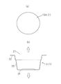
- FIG. 1 is a cross-sectional view of a metal laminate packaging material of the present invention
- FIG. (a) is a plan view of a molding blank that provides the molded container of the present invention.
- (b) is a cross-sectional view of a molded container obtained from the molding blank.
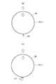
- (a) is a plan view of a body blank that provides the body of the combination container of the present invention.
- (b) is a perspective view of a trunk obtained from the trunk blank.
- (a) is a plan view of a bottom blank that provides the bottom of the combination container of the present invention;
- (b) is a perspective view of a bottom formed from the bottom blank.
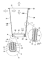
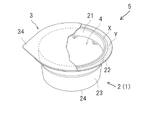
- 1 is a perspective view of a combination container according to the invention; FIG. FIG.
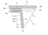
- FIG. 6 is a horizontal cross-sectional view showing an enlarged overlapping portion of the body of the combination container of FIG. 5;
- FIG. 6 is a vertical cross-sectional view along line V-V in the combination container of FIG. 5;
- the portion surrounded by the dashed line A is an enlarged view of the folding portion surrounded by the dashed line a.
- the portion surrounded by the dashed-dotted line B is an enlarged view of the overlapping portion surrounded by the dashed-dotted line b.
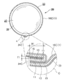
- FIG. 6 is a vertical cross-sectional view showing part of a process for manufacturing the combination container of FIG. 5;
- FIG. 4 is a vertical cross-sectional view showing part of the process for manufacturing the combination container of the present invention;
- FIG. 10 is a top view of the combination container of FIG. 9; In the figure, the portion surrounded by the dashed-dotted line C is an enlarged view of the overlapping portion surrounded by the dashed-dotted line c in the combination container.
- FIG. 2 is a perspective view of a package having the molded container of the present invention as an element; 12 is a partial cross-sectional view of the package of FIG. 11; FIG. 1 is a partial cross-sectional view of a package having the combination container of the present invention as an element; FIG.
- “Inside” refers to the direction of the heat-sealable layer side of both sides of the metal laminate packaging material of the present invention, and the upward arrows in FIGS. can be regarded as the direction of Further, the same direction is, for example, the upward arrow direction in FIG. 2(b), the right arrow direction in FIG. 5, the upward arrow direction in FIG.
- the arrow direction means the downward arrow direction in FIG.
- Outside refers to the opposite side of the heat-sealable layer on both sides of the metal laminate packaging material of the present invention, and each of FIGS. It can be regarded as the direction of the down arrow. Further, the same direction is, for example, the downward arrow direction in FIG. 2(b), the left arrow direction in FIG. 5, the downward arrow direction in FIG. 6, the leftward direction in FIG. The arrow direction means the upward arrow direction in FIG.
- Upward refers to the direction of the opening side of the container of the present invention with respect to the center of the body of the container, for example, the direction of the upward arrow in FIG.
- Bottom refers to the side opposite to the opening of the container of the present invention, that is, the direction toward the bottom, with the center of the body of the container of the present invention as a reference, for example, the direction of the downward arrow in FIG.
- Biomass refers to renewable, biologically derived organic resources. Biomass can be classified into waste biomass, unused biomass, and resource crops according to its state of existence. Waste biomass includes, for example, waste paper and wood from construction. Unused biomass includes, for example, various straws and forest residues. Examples of resource crops include carbohydrate resources such as sugarcane, starch resources such as corn, and oil resources such as rapeseed.
- Biomass-derived resin refers to a resin synthesized using raw materials derived from the biomass (hereinafter sometimes identified as bio-).
- “Fossil resource-derived resin” refers to resin synthesized using only raw materials derived from fossil resources (hereinafter sometimes identified as fuel-), and is distinguished from biomass-derived resin.
- Resins include one or both of biomass-derived resins and fossil resource-derived resins.
- Suitable biomass-derived resins include at least one selected from the group consisting of biomass-derived polyolefins (bio-polyolefins), biomass-derived polyesters (bio-polyesters), and biomass-derived polyamides (bio-polyamides).
- Biomass-derived polyolefins are polymers obtained from biomass-derived olefins (bio-olefins).
- Bio-olefins can be obtained by olefinizing bio-alcohols (bio-ethanol, bio-isopropanol, bio-butanol, etc.) obtained from sugar resources among the above-mentioned biomass by various known methods, and bio-ethylene, bio-propylene and bio-butene can be obtained.
- bio-olefins and olefins derived from fossil resources fuel-olefins
- composition ratio of bio-olefins and fuel-olefins in biomass-derived polyolefins is not particularly limited as long as bio-olefins are 10% by mass or more in all olefins, and is determined taking economic efficiency into account.
- the bio-olefin/fuel-olefin mass ratio is, for example, about 10/90 to 50/50, more preferably about 20/80 to 30/70.
- biomass-derived polyolefins include biomass-derived polyethylene (bio-PE), biomass-derived ethylene-propylene random copolymer (bio-rPP), biomass-derived ethylene-propylene block copolymer (bio-bPP), and biomass-derived homopolypropylene ( bio-hPP) and the like.
- bio-PE biomass-derived polyethylene
- bio-rPP biomass-derived ethylene-propylene random copolymer
- bio-bPP biomass-derived ethylene-propylene block copolymer
- bio-hPP biomass-derived homopolypropylene
- Biomass-derived polyesters are polymers obtained from raw materials such as lactones, polyols, polycarboxylic acids and hydroxycarboxylic acids.
- the raw material may be wholly derived from biomass, or may be a combination of a biomass-derived raw material and a fossil resource-derived raw material.
- Lactones include ⁇ -butyrolactone, ⁇ -valerolactone, ⁇ -caprolactone and the like.
- polyols examples include aliphatic, alicyclic and aromatic diols such as ethylene glycol, propylene glycol, butanediol, neopentyl glycol, diethylene glycol, polyethylene glycol, cyclohexanedimethanol, bisphenol A and bisphenol A-alkylene oxide adducts, and tri- to tetraols such as glycerin, trimethylolpurpan, trimethylolethane, pentaerythritol, diglycerin, ditrimethylolpropane and ditrimethylolethane.
- diols such as ethylene glycol, propylene glycol, butanediol, neopentyl glycol, diethylene glycol, polyethylene glycol, cyclohexanedimethanol, bisphenol A and bisphenol A-alkylene oxide adducts
- tri- to tetraols such as glycerin, trimethylo
- polycarboxylic acids examples include terephthalic acid, isophthalic acid, naphthalenedicarboxylic acid, cyclohexanedicarboxylic acid, adipic acid, azelaic acid, sebacic acid, maleic acid, maleic anhydride and fumaric acid.
- examples include dicarboxylic acids, and tri- to tetracarboxylic acids such as trimellitic acid, trimellitic anhydride, pyromellitic acid and pyromellitic anhydride.
- Hydroxycarboxylic acids include, for example, p-hydroxybenzoic acid, p-hydroxyethoxybenzoic acid, citric acid, malic acid and tartaric acid.
- biomass-derived polyesters include biomass-derived polyethylene terephthalate (bio-PET) and biomass trimethylene terephthalate (bio-PTT).
- bio-PET biomass-derived polyethylene terephthalate
- bio-PTT biomass trimethylene terephthalate
- Ethylene glycol (EG) of biomass PET can be made from sugar resource-derived bioethanol among the biomass, and terephthalic acid (TPA) is also made from such sugar resource-derived paraxylene (PX) as a raw material.
- PX sugar resource-derived paraxylene
- Biomass-derived polyamides are polymers obtained from raw materials such as lactones, diamines and dicarboxylic acids.
- the raw materials for the polyamide may all be derived from biomass, or may be a combination of raw materials derived from biomass and raw materials derived from fossil resources.
- Biomass-derived polyamides include n-nylon, which is a polycondensation reaction product of ⁇ -amino acids, and n,m-nylon, which is a co-condensation reaction product of diamines and dicarboxylic acids.
- n and m indicate the number of carbon atoms in the monomer component.
- Examples of n-nylon include nylon 6, 11, 12 and the like.
- n,m-nylon examples include nylon 66, 410, 510, 56, 610, 1012, 6T, 6I and 10T.
- Lactones include, for example, ⁇ -caprolactam, undecanelactam and lauryllactam.
- Diamines include, for example, hexamethylenediamine.
- dicarboxylic acids include adipic acid, sebacic acid, terephthalic acid and isophthalic acid.
- biomass-derived resins include polycarbonate, phenol resin, and cellulose acetate resin.
- suitable fossil resource-derived resins include fossil resource-derived polyolefin (fuel-polyolefin), fossil resource-derived polyester (fuel-polyester), and fossil resource-derived polyamide (fuel-polyamide).
- Fossil resource-derived polyolefins are polymers obtained only from olefins derived from fossil resources (fuel-olefins).
- Specific examples of fossil resource-derived polyolefins include fossil resource-derived polyethylene (fuel-PE), fossil resource-derived ethylene-propylene random copolymer (fuel-rPP), fossil resource-derived ethylene-propylene block copolymer (fuel-bPP), and fossil resource-derived polyolefins.
- At least one polyolefin selected from the group consisting of resource-derived homopolypropylene (fuel-hPP) and the like can be mentioned.
- Fossil-derived polyolefins are available in low, medium and high density types and may be modified with unsaturated dicarboxylic acids such as (anhydrous) maleic acid.
- Fossil resource-derived polyesters are polymers obtained from raw materials such as lactones, polyols, polycarboxylic acids and hydroxycarboxylic acids.
- all of the raw materials are derived from fossil resource-derived raw materials.
- Lactones include ⁇ -butyrolactone, ⁇ -valerolactone, ⁇ -caprolactone and the like.
- polyols examples include aliphatic, alicyclic and aromatic diols such as ethylene glycol, propylene glycol, butanediol, neopentyl glycol, diethylene glycol, polyethylene glycol, cyclohexanedimethanol, bisphenol A and bisphenol A-alkylene oxide adducts, and tri- to tetraols such as glycerin, trimethylolpurpan, trimethylolethane, pentaerythritol, diglycerin, ditrimethylolpropane and ditrimethylolethane.
- diols such as ethylene glycol, propylene glycol, butanediol, neopentyl glycol, diethylene glycol, polyethylene glycol, cyclohexanedimethanol, bisphenol A and bisphenol A-alkylene oxide adducts
- tri- to tetraols such as glycerin, trimethylo
- polycarboxylic acids examples include terephthalic acid, isophthalic acid, naphthalenedicarboxylic acid, cyclohexanedicarboxylic acid, adipic acid, azelaic acid, sebacic acid, maleic acid, maleic anhydride and fumaric acid.
- examples include dicarboxylic acids, and tri- to tetracarboxylic acids such as trimellitic acid, trimellitic anhydride, pyromellitic acid and pyromellitic anhydride.
- Hydroxycarboxylic acids include, for example, p-hydroxybenzoic acid, p-hydroxyethoxybenzoic acid, citric acid, malic acid and tartaric acid.
- Specific examples of fossil resource-derived polyesters include fossil resource-derived polyethylene terephthalate (fuel-PET) and fossil resource-derived trimethylene terephthalate (fuel-PTT). Terephthalate (fuel-PET) is preferred.
- Polyamides derived from fossil resources are polymers obtained from raw materials such as lactones, diamines and dicarboxylic acids.
- All of the raw materials are derived from fossil resources.
- Polyamides derived from fossil resources include n-nylon, which is a polycondensation reaction product of ⁇ -amino acids, and n,m-nylon, which is a co-condensation reaction product of diamines and dicarboxylic acids.
- n and m indicate the number of carbon atoms in the monomer component.
- Examples of n-nylon include nylon 6, 11, 12 and the like.
- Examples of n,m-nylon include nylon 66, 410, 510, 56, 610, 1012, 6T, 6I and 10T.
- Lactones include, for example, ⁇ -caprolactam, undecanelactam and lauryllactam.
- Diamines include, for example, hexamethylenediamine.
- dicarboxylic acids include adipic acid, sebacic acid, terephthalic acid and isophthalic acid.
- Examples of other fossil resource-derived resins include fossil resource-derived polycarbonates and fossil resource-derived phenolic resins.
- the biomass-derived resin and/or the fossil resource-derived resin may be combined with various elastomers, tackifiers, waxes, pigments, and the like as auxiliary materials.
- elastomers include polystyrene-based elastomers and polyolefin-based elastomers.
- the elastomer may be biomass-derived, fossil resource-derived, or a combination of both.
- the tackifying resin include rosins such as rosin, disproportionated rosin, hydrogenated rosin and polymerized rosin, derivatives thereof (alcohol esters and the like), and the like.
- wax include polyethylene wax, polypropylene wax and amide wax.
- Pigments include titanium oxide, zinc white, gloss white, palite, barium carbonate, calcium carbonate, precipitated silica, aerosil, talc, alumina white, mica, synthetic calcium silicate, magnesium carbonate, barium carbonate, carbon black, magnetite and Bengara and the like can be mentioned.
- the objects of the present invention are a metal laminate packaging material (1) (hereinafter sometimes abbreviated as packaging material (1)), a container (2), and a package (5).
- the container (2) is an article obtained by processing the packaging material (1). ) and a bottom portion (27) surrounded by a lower peripheral edge of the bottom portion (27).
- the "cylindrical" representing the shape of the body (23) refers to a hollow shape with both ends open and surrounded by walls. is not particularly limited.
- the term “cylindrical” includes both those having a constant cross-sectional shape and area in the length direction and those having a cross-sectional shape and/or area that change in the length direction.
- Examples of the container (2) in this specification include a molded container (2A), a combination container (2B), and a combination container (2C), which will be described later.
- the package (5) is a sealed body consisting of a container (2), a lid (3), and contents (4).
- the packaging material (1) is a laminated material comprising at least a thermal adhesive layer (11), a barrier layer (13) and a protective layer (15), and does not have a paper layer.
- the heat-sealable layer (11) is laminated inside the barrier layer (13) and is made of a heat-sealable resin.
- the heat-sealable layer (11) may be a single layer or multiple layers.
- the multilayer heat sealing layer (11) is composed of at least two independent layers.
- the two-layer heat sealing layer (11) consists of a single outermost heat sealing layer (11a) and a single innermost heat sealing layer (11c).
- the three or more heat sealing layers (11) consist of a single outermost heat sealing layer (11a), a single or multiple intermediate heat sealing layer (11b), and a single innermost heat sealing layer. It consists of a layer (11c).
- An adhesive layer (12) may be interposed between the thermal adhesive layer (11) and the barrier layer (13).
- An adhesive layer (14) may also be interposed between the barrier layer (13) and the protective layer (15).
- the protective layer (15) is laminated inside the barrier layer (13) and is made of film-like synthetic resin.
- the protective layer (15) may be a single layer or multiple layers.
- the multilayer protective layer (15) consists of at least two independent layers.
- the two-layered protective layer (15) consists of a single outermost heat sealing layer (15a) and a single innermost heat sealing layer (15c).
- the three or more protective layers (15) consist of a single outermost heat sealing layer (15a), a single or multiple intermediate heat sealing layer (15b), and a single innermost heat sealing layer. Consists of (15c).
- FIG. 1 illustrates a specific form of the packaging material (1) of the present invention.
- the packaging material (1) in FIG. 1(a) is the first embodiment.
- the same form consists of a heat-sealable layer (11), an adhesive layer (12) (optional), a barrier layer (13), an adhesive layer (14) (optional) and a protective layer (15) in order from the inside.
- the packaging material (1) in FIGS. 1(b), 1(c) and 1(d) is a modification of the first embodiment.
- the packaging material (1) in FIG. 1(b) is the second embodiment.
- only the heat sealing layer (11) is a multilayer, and from the inside, the outermost heat sealing layer (11a), the middle heat sealing layer (11b) and the innermost heat sealing layer (11c).
- the packaging material (1) in FIG. 1(c) is the third embodiment.
- only the protective layer (15) is a multi-layered structure consisting of an innermost protective layer (15a), an intermediate protective layer (15b) and an outermost protective layer (15c) in order from the inside.
- the packaging material (1) in FIG. 1(d) is the fourth embodiment.
- the heat sealing layer (11) consists of an outermost heat sealing layer (11a), an intermediate heat sealing layer (11b) and an innermost heat sealing layer (11c) in order from the inside
- a protective layer (15) consists of an innermost protective layer (15a), an intermediate protective layer (15b) and an outermost protective layer (15c) in order from the inside.
- the heat-fusible resin forming the heat-fusible layer (11) and/or the film-like synthetic resin forming the protective layer (15) contain a biomass-derived resin.
- Three modes are given below.
- Aspect 1 The heat-fusible resin forming the heat-fusible layer (11) contains a biomass-derived resin, and the synthetic resin forming the protective layer (15) does not contain a biomass-derived resin.
- Aspect 2 The heat-fusible resin forming the heat-fusible layer (11) contains a biomass-derived resin, and the synthetic resin forming the protective layer (15) also contains a biomass-derived resin.
- Aspect 3 The heat-fusible resin forming the heat-fusible layer (11) does not contain a biomass-derived resin, and the synthetic resin forming the protective layer (15) contains a biomass-derived resin.
- the thermal fusion layer (11) is conceived as a single layer or multiple layers.
- the heat-fusible layer (11), which is a single layer, is composed of a layer made of a heat-fusible resin, and the heat-fusible resin is composed of a biomass-derived resin and/or a fossil resource-derived resin.
- the heat sealing layer (11), which is a single layer is composed of a biomass-derived resin.
- the thickness of the heat-sealable layer (11), which is a single layer is not limited, and is, for example, 25 ⁇ m to 500 ⁇ m in consideration of heat sealability.
- the thickness is preferably 30 ⁇ m to 400 ⁇ m from the viewpoint of optimizing heat-sealing property and content resistance.
- the thermal adhesive layer (11), which is a multilayer, is composed of two or more independent layers made of a thermal adhesive resin, and the thermal adhesive resin is composed of a biomass-derived resin and/or a fossil resource-derived resin. do.
- the protective layer (15) does not contain a biomass-derived resin layer
- the multi-layer heat-sealable layer (11) contains a layer made of a biomass-derived resin.
- the multilayer heat sealing layer (11) is composed of an outermost heat sealing layer (11a), an intermediate heat sealing layer (11b) and an innermost heat sealing layer (11c) in order from the inside.
- the intermediate heat sealing layer (11b) is optional and can be omitted.
- the outermost heat-sealable layer (11a), omitting the intermediate heat-sealable layer (11b) and the innermost heat-sealable layer (11c), can be regarded as a single heat-sealable layer (11).
- the total thickness of the heat-sealable layer (11), which is a multilayer, is not particularly limited, and in consideration of sealing properties, corrosion of the barrier layer (13) by the contents (4), etc., it is, for example, 25 ⁇ m to 500 ⁇ m, preferably 30 ⁇ m. ⁇ 400 ⁇ m.
- the outermost heat-sealable layer (11a) is a single layer forming the inner surface of the housing portion of the container (2) and the upper surface of the flange portion (22) of the container (2). Direct heat-sealing of the outermost heat-sealable layer (11a) and the heat-sealable layer forming the lower surface of the lid (3) realizes heat-sealing of the container (2).
- the thickness of the outermost heat sealing layer (11a) is not particularly limited, and is, for example, 2 ⁇ m to 100 ⁇ m, preferably 3 ⁇ m to 60 ⁇ m.
- the intermediate heat-fusible layer (11b) can be defined as the layer remaining after removing the outermost heat-fusible layer (11a) and the innermost heat-fusible layer (11c) from the multilayer heat-fusible layer (11). , may be a single layer or multiple layers.
- the intermediate heat-sealable layer (11b) indirectly performs heat-sealing between the outermost heat-sealable layer (11a) and the heat-sealable layer forming the lower surface of the lid (3). It acts as a bonding layer between (11a) and the innermost heat sealing layer (11c), and also functions as a reinforcing layer that enhances the strength of the entire heat sealing layer (11).
- the number of intermediate heat-sealable layers (11b) is not particularly limited, and is, for example, 1-7.
- the total thickness of the intermediate heat-sealing layer (11b) is not particularly limited, and is, for example, 15 ⁇ m to 160 ⁇ m, preferably 20 ⁇ m to 64 ⁇ m.
- the innermost heat-fusible layer (11c) is the innermost single layer of the multilayer heat-fusible layer (11), and the multilayer heat-fusible layer (11) and the printing ink layer (optional) and/or responsible for bonding with the barrier layer (13).
- the thickness of the innermost heat sealing layer (11c) is not particularly limited, and is, for example, 2 ⁇ m to 100 ⁇ m, preferably 3 ⁇ m to 60 ⁇ m.
- the outermost heat sealing layer (11a), the middle heat sealing layer (11b) (optional), and the innermost heat sealing layer (11c) are all made of biomass-derived resin.
- some layers may be composed of a biomass-derived resin and other layers may be composed of a fossil resource-derived resin.
- the intermediate heat-sealing layer (11b) has a multi-layer structure, some layers can be made of biomass-derived resin and other layers can be made of fossil resource-derived resin.
- the stacking order of the biomass-derived resin layer and the fossil resource-derived resin layer is arbitrary and not particularly limited.
- the polyolefin those already mentioned can be used, and at least one selected from the group consisting of biomass-derived polyethylene, biomass-derived ethylene-propylene random copolymer and biomass-derived ethylene-propylene block copolymer is particularly preferable.
- the already mentioned fossil resource-derived polyolefin can be mentioned.
- the polyolefin those already mentioned can be used, and at least one selected from the group consisting of fossil resource-derived polyethylene, fossil resource-derived ethylene-propylene random copolymer and fossil resource-derived ethylene-propylene block copolymer is particularly preferable.
- the heat-sealable layer (11), which is a multilayer, can be formed by various known methods such as dry lamination, melt extrusion lamination, heat lamination, and gravure coating. These methods may be combined.
- the adhesive layer (12) By interposing the adhesive layer (12) between the thermal adhesive layer (11) and the barrier layer (13), delamination between the two layers can be prevented when the packaging material (1) is processed.
- adhesives constituting the adhesive layer (12) include vinyl chloride-vinyl acetate copolymer adhesives, polyester adhesives, epoxy adhesives, polyolefin adhesives, and polyurethane adhesives. Polyurethane resin-based adhesives are preferred.
- the polyurethane resin adhesive a two-component curable polyurethane resin adhesive is preferable, and a two-component curable polyether urethane resin-based adhesive and/or a two-component curable polyester urethane resin-based adhesive is particularly preferable.
- the adhesive may also be one using a biomass-derived raw material.
- the thickness of the adhesive layer (12) is not particularly limited, and is, for example, 1 ⁇ m to 8 ⁇ m, preferably 2 ⁇ m to 6 ⁇ m, from the viewpoint of preventing delamination.
- the barrier layer (13) is a layer for protecting the contents (4) of the package (5) from gas, water vapor, light, etc., and is made of metal foil.
- the metal foil examples include aluminum foil, iron foil, stainless steel foil, copper foil, nickel foil, and the like, and aluminum foil is preferable in consideration of barrier function, formability, cost, and the like.
- the aluminum foil examples include pure aluminum foil and aluminum alloy foil, and a soft material (O material) is preferable.
- A1000 series or A8000 series aluminum foil specified by JIS H4160 is suitable. It is preferable in terms of moldability, and can prevent delamination during molding and prevent unevenness in molding height.
- the A8079-H material or A8021-H material which are hard materials, is used, the overall strength of the container (2), especially the strength of the flange (22), is increased, so that the flange (22) may be damaged by an unexpected impact. ) can be suppressed. Also, the shape retention of the entire container (2) is improved.
- a base layer (not shown) made of a predetermined chemical conversion treatment solution can be formed on the inner surface and/or the inner surface of the metal foil.
- the chemical conversion treatment solution include a water-alcohol solution containing phosphoric acid, a chromium-based compound, a fluorine-based compound and/or a binder resin.
- the amount of the chemical conversion treatment solution used is not particularly limited, as long as the amount of chromium adhered per side of the metal foil is, for example, 0.1 mg/m 2 to 50 mg/m 2 , preferably 2 mg/m 2 to 20 mg/m 2 . Just do it.
- the thickness of the barrier layer (13) is not particularly limited. It can be determined in consideration of shape retention and the like, and is, for example, 40 ⁇ m to 200 ⁇ m, preferably 80 ⁇ m to 160 ⁇ m.
- the amount of metal foil used in the packaging material (1) is not particularly limited, but considering the desired barrier function of the barrier layer (13) and the recyclability of the metal foil, the unit area of the packaging material (1)
- the amount used per unit is 50% to 90%, preferably 65% to 85%, more preferably 55% to 80%, based on mass.
- the "mass standard” means the mass ratio of the metal foil per unit area to the mass per unit area of the packaging material (1).
- the adhesive layer (14) By interposing the adhesive layer (14) between the barrier layer (13) and the protective layer (15), delamination between the two layers can be prevented when the packaging material (1) is processed.
- the adhesive that forms the adhesive layer (14) the adhesive that forms the adhesive layer (12) can be used, and a two-part curable polyurethane adhesive is particularly suitable.
- the thickness of the adhesive layer (14) is not particularly limited, and is 1 ⁇ m to 8 ⁇ m, preferably 2 ⁇ m to 6 ⁇ m, considering the delamination preventive effect.
- the printing ink is a composition obtained by dispersing a coloring material such as a pigment or a dye in a vehicle containing a binder resin and an organic solvent, and various known inks can be used without particular limitation.
- the protective layer (15) is conceived as a single layer or multiple layers.
- the protective layer (15), which is a single layer, is composed of a film-like synthetic resin layer, and the synthetic resin is composed of a biomass-derived resin and/or a fossil resource-derived resin.
- the protective layer (15), which is a single layer is made of a biomass-derived resin.
- the thickness of the protective layer (15), which is a single layer is not particularly limited. , for example 15 ⁇ m to 200 ⁇ m, preferably 20 ⁇ m to 60 ⁇ m.
- the multilayer protective layer (15) is composed of two or more independent film-like synthetic resin layers, and the synthetic resin is composed of a biomass-derived resin and/or a fossil resource-derived resin.
- the multilayer protective layer (15) contains a layer made of a biomass-derived resin.
- the multilayer protective layer (15) is composed of an innermost protective layer (15a), an intermediate protective layer (15b) and an outermost protective layer (15c) in order from the inside.
- the intermediate protective layer (15b) is optional and can be omitted.
- the remaining innermost protective layer (15a), omitting the intermediate protective layer (15b) and the innermost protective layer (15c), can be regarded as a single-layer protective layer (15).
- the overall thickness of the multilayer protective layer (15) is not particularly limited, and is, for example, 15 ⁇ m to 200 ⁇ m, preferably 20 ⁇ m to 60 ⁇ m in consideration of corrosion resistance and the like.
- the innermost protective layer (15a) is a layer that joins the barrier layer (13) or adhesive layer (14) and the protective layer (15).
- the thickness of the innermost protective layer (15a) is not particularly limited, and is, for example, 2 ⁇ m to 100 ⁇ m, preferably 3 ⁇ m to 60 ⁇ m.
- the intermediate protective layer (15b) is defined as the layers remaining after removing the innermost protective layer (15a), which is a single layer, and the outermost protective layer (15c), which is also a single layer, from the multilayer protective layer (15). can.
- the intermediate protective layer (15b) is a single layer or multiple layers.
- the intermediate protective layer (15b) acts as a bonding layer between the innermost protective layer (15a) and the outermost protective layer (15c), and also functions as a reinforcing layer that increases the strength of the protective layer (15) as a whole.
- the number of layers of the intermediate protective layer (15b) is not particularly limited, and is, for example, 1-4.
- the total thickness of the intermediate protective layer (15b) is not particularly limited, and is, for example, 15 ⁇ m to 160 ⁇ m, preferably 20 ⁇ m to 64 ⁇ m.
- the outermost protective layer (15c) is a layer that constitutes the outermost surfaces of the molded container (2) and the package (5), and directly serves to protect them from the impact of dropping and the force applied from the outside. Fulfill.
- the thickness of the outermost protective layer (15c) is not particularly limited, and is, for example, 2 ⁇ m to 100 ⁇ m, preferably 3 ⁇ m to 60 ⁇ m.
- the innermost protective layer (15a), the intermediate protective layer (15b) (optional), and the outermost protective layer (15c) may all be made of biomass-derived resin.
- a part layer may be composed of a biomass-derived resin, and other layers may be composed of a fossil resource-derived resin.
- the intermediate protective layer (15b) is multi-layered, some layers can be made of biomass-derived resin and other layers can be made of fossil resource-derived resin.
- the stacking order of the biomass-derived resin layer and the fossil resource-derived resin layer is arbitrary and is not particularly limited.
- biomass-derived resin that can constitute the protective layer (15) examples include the biomass-derived polyester and/or biomass-derived polyolefin already described.
- polyester those already mentioned can be used.
- polyolefin those already mentioned can be used, and in particular, at least one selected from the group consisting of biomass-derived polyethylene, biomass-derived ethylene-propylene random copolymer and biomass-derived ethylene-propylene block copolymer is preferable.
- Examples of the fossil resource-derived resin that can constitute the protective layer (15) include the already mentioned fossil resource-derived polyester and/or fossil resource-derived polyolefin.
- As the polyester those already mentioned can be used.
- the polyolefin is preferably at least one selected from the group consisting of fossil resource-derived polyethylene, fossil resource-derived ethylene-propylene random copolymer, and fossil resource-derived ethylene-propylene block copolymer.
- the film-like synthetic resin that forms the protective layer (15) may have heat-sealing properties regardless of whether the layer (15) is single-layered or multi-layered.
- the packaging material (1) in which the protective layer (15) is made of a heat-sealable film-like synthetic resin is useful in the case of producing combination containers (2B) and (2C) described later among the containers (2). is.
- the multilayer protective layer (15) can be formed by various known methods such as dry lamination, melt extrusion lamination, heat lamination, and gravure coating. These methods may be combined.
- the protective layer (15) behaves as follows during the molding process of the packaging material (1). That is, for example, when a circular molding blank (10A) made of the packaging material (1) is subjected to press working, particularly deep drawing, in order to produce a molded container (2A) described later, the blank (10A) is Of the region to be molded, the portion corresponding to the flange portion (22) of the molded container (2A) is compressed, while the portion corresponding to the body portion (23) is stretched. In particular, the portion corresponding to the rounded portion forming the boundary between the trunk portion (23) and the bottom portion (27) is further stretched.
- the film-like synthetic resin forming the entire protective layer (15) preferably has the following characteristic configuration 1.
- Characteristic structure 1 Tensile modulus of elasticity ( ⁇ 1 (MD) ) in the machine direction (MD) of the film-like synthetic resin is limited to 500 MPa to 2500 MPa (preferably 500 MPa to 1000 MPa), and tensile elasticity in the width direction (TD)
- the ratio ( ⁇ 1 (TD) ) is also limited to 500 MPa to 2500 MPa (preferably 500 MPa to 1000 MPa), and the ratio of both tensile strengths ( ⁇ 1 (MD) / ⁇ 1 (TD) ) is 0.9 to 1.1 (preferably is limited to 0.95 to 1.05).
- the entire protective layer (11) is composed of a film-like synthetic resin having characteristic structure 1, the formability of the packaging material (1) is improved. Delamination with the layer (13) can be prevented. In addition, it becomes easy to secure the molding height of the molded container (2A) made of the same packaging material (1) and the bottom portion (27) described later.
- the film-like synthetic resin forming the protective layer (15) is further provided with characteristic configuration 2 and/or characteristic configuration 3 below.
- Characteristic configuration 2 The tensile strength ( ⁇ 2 (MD) ) at break in the machine direction (MD) of the film-like synthetic resin is limited to 30 MPa to 70 MPa (preferably 30 MPa to 50 MPa), and in the width direction (TD) The tensile strength at break ( ⁇ 2 (TD) ) is also limited to 30 MPa to 70 MPa (preferably 30 MPa to 50 MPa), and their ratio ( ⁇ 2 (MD) / ⁇ 2 (TD) ) is 0.9 to 1.1. (preferably 0.95 to 1.05).
- Characteristic configuration 3 The tensile elongation (E (MD) ) at break in the machine direction (MD) of the film-like synthetic resin is limited to 500% to 900% (preferably 500% to 800%), and the width direction (TD ) at break (E (TD) ) is also limited to 500% to 900% (preferably 500% to 800%), and their ratio (E (MD) /E (TD) ) is 0.8 ⁇ 1.2 (preferably 0.9-1.1).
- the film-like synthetic resin forming the protective layer (15) has all of the characteristic configurations 1, 2 and 3.
- characteristic configurations 1, 2 and 3 are measured values according to JIS K 7161 and JIS K 7127 ("Testing methods for plastic tensile properties").
- the packaging material (1) can be manufactured by various known methods such as dry lamination, melt extrusion lamination, heat lamination, etc. These methods may be combined.
- the container (2) has at least an opening (21), a body (23), and a bottom (27), as described above.
- the container (2) includes the molded container (2A) and the combination container (2B) and combination container (2C). They will be explained in order below.
- the molded container (2A) is an article formed by molding a molding blank (10A) made of the packaging material (1), and has an opening (21). In addition, it is an integrated container in which the body (23) and the bottom (27) are continuous. A flange portion (22) may be formed along the periphery of the opening (21).
- FIG. 2(a) is one form of a molding blank (10A).
- the shape is not particularly limited, and may be a circle as shown in the figure, or a polygonal shape such as a rectangle (not shown).
- the molding blank (10A) is not essential.
- the packaging material (1) of unspecified shape is molded as it is to produce a molded container (2A)
- the forming blank (10A) can be disregarded.
- the forming processing means is not particularly limited, and examples thereof include deep drawing and stretch forming.
- FIG. 2(b) is a cross-sectional view of the molded container (2A).
- the molded container (2A) is cup-shaped, and a brim-shaped flange (22) is formed around the periphery of the opening (21).
- the size and shape of the flange portion (22) are not particularly limited, and are determined appropriately as long as the lid (3) can be heat-sealed on the upper surface thereof and the package (5) can be sealed after heat-sealing. can.
- the flange portion (22) may have an annular shape, or, although not shown, may have a polygonal annular shape.
- a step is formed in the middle of the height of the body (23) of the molded container (2A), and a convex portion is provided on the bottom (27), but these configurations are arbitrary. . Such an optional configuration can enhance the mechanical strength and stackability of the molded container (2A).
- Both combination containers (2B) and (2C) are combined containers having a cylindrical body (23) and a bottom (27) joined to the lower peripheral edge of the body (23). .
- a brim-shaped flange (22) may be formed on the periphery of the opening (21).
- FIG. 3(a) is a plan view of the trunk blank (10B) that provides the trunk (23).
- the blank (10B) is fan-shaped, but this is an example, and the shape can be set according to the shape of the combination container (2B).
- FIG. 3(b) is a perspective view of the trunk (23) obtained from the trunk blank (10B).
- the trunk portion (23) is a tapered cylindrical member, and is formed by overlapping and joining both end edges of the fan-shaped trunk blank (10B). Therefore, the trunk (23) has an overlapping portion (24B) extending along its height direction.
- FIG. 4(a) is a plan view of the bottom blank (10C) that provides the bottom (27).
- the blank (10C) has a circular shape, but this is an example, and the shape can be set according to the shape of the combination container (2B).
- FIG. 4(b) is a perspective view of the bottom (27) obtained from the bottom blank (10C).
- the bottom portion (27) is, for example, a member with a substantially inverted U-shaped cross section formed by deep drawing a circular bottom blank (10C), and is composed of a circular and horizontal body portion (28) and the body portion (28). and a hanging portion (29) extending upward from the outer peripheral edge.
- Fig. 5 is a perspective view of the combination container (2B).
- the container (2B) is cup-shaped, and is integrally joined by sealing the body (23) and the bottom (27).
- FIG. 6 is a cross-sectional view of the overlapping portion (24B) of the body portion (23).
- the overlap portion (24B) is formed by overlapping one edge portion and the other edge portion of the fan-shaped trunk blank (10B).
- Total thickness (T1) of overlapping of the protective layer (15) on one edge of the body blank (10B) and the heat-sealable layer (11) on the other edge in the overlapping portion (24B) is not particularly limited, and is, for example, 55 ⁇ m to 195 ⁇ m.
- the thickness (T1) is preferably 60 ⁇ m to 190 ⁇ m.
- the width (W1) of the overlapping portion (24B) is also not particularly limited, and is, for example, 2 mm to 10 mm. By setting the same width (W1) to 2 mm or more, it is possible to sufficiently secure the barrier property and sealing property of the overlapping portion (24B). Also, by setting the overlapping width (W1) to less than 10 mm, it is possible to reduce costs and prevent wrinkles in the overlapping portion (24B). From the above point of view, the same width (W1) is preferably 4 mm to 8 mm.
- FIG. 7 is a cross-sectional view of the combination container (2B).
- the portion surrounded by the dashed-dotted line A on the outer side of the body (23) is an enlarged view of the overlapping portion (24B) surrounded by the dashed-dotted line b.
- an outwardly bent flange portion (22) is provided at the edge of the opening (21) on the upper end side of the body portion (23).
- the flange portion (22) is optional, and may have a form other than that shown. For example, it may be formed in a flat shape folded in three, or may be curled downward and formed into a generally arcuate cross section.
- the lower edge of the body (23) is formed with an inwardly folded folded portion (25) as indicated by the portion surrounded by the dashed line b.
- An enlarged view of the folded portion (25) is shown by a portion surrounded by a dashed line B. As shown in FIG.
- a trunk blank (10B) and a bottom blank (10C) are produced.
- the trunk blank (10B) is obtained, for example, by punching the packaging material (1) into a fan shape of a predetermined size, as shown in FIG. 3(a).
- the bottom blank (10C) is obtained, for example, by punching out a circle of predetermined size from the packaging material (1), as shown in FIG. 4(a).
- the packaging material (1) constituting the trunk blank (10B) and the packaging material (1) constituting the bottom blank (10C) are usually the same, but differ in material and/or thickness. You can let
- the bottom part (27), for example, as shown in FIG. 4(b), is obtained by deep drawing a circular bottom part blank (10C) using a die (not shown).
- the bottom part (27) in the figure is a component with an inverted U-shaped cross section, consisting of a circular horizontal body part (28) and a hanging part (29) rising from the periphery of the body part (28).
- the bottom part (27) is preferably manufactured so that the surface of the hanging part (28) in particular is not wrinkled. By suppressing wrinkles, the bottom part (27) and the body part (23) can be easily joined integrally, and leakage can be prevented even when the liquid content (4) is stored in the combination container (2B).
- the corner portion between the body portion (28) and the drooping portion (29) on the outer surface of the bottom portion (27) has a substantially right-angled cross section, but may be rounded.
- the bottom (27) and the body blank (10B) are joined. Specifically, after setting the bottom part (27) on the top surface of a mold (not shown) having a substantially truncated cone shape so that the upper surface of the main body part (28) overlaps, the outer periphery of the mold is After wrapping the body blank (10B) around the surface and overlapping the both edges, the heat-sealing layer (11) and the protective layer ( 15) is heat-sealed to form a tapered tubular body (23).
- FIG. 8 shows the process of forming the flange portion (22) and the folded portion (25).
- the flange portion (22) is formed by curling the upper edge of the body portion (23) outward using a predetermined curling mold (not shown) at the horizontal position of the opening (21) indicated by the two-dot chain line. , pressurized in the vertical direction to form a substantially horizontal two-fold flat shape.
- the folded portion (25) is a portion that assists the joining of the body portion (23) and the bottom portion (27), and the joining is performed by heat sealing.
- the heat-sealing is performed between the heat-sealing layer (11) at the lower end (26) of the trunk (23) and the protective layer (15) of the drooping portion (29) of the bottom (27), as well as on the same bottom. It is realized between the heat-sealing layer (11) of (27) and the heat-sealing layer (11) of the folded portion (25).
- the folded portion (25) is optional. In this case, after fitting the cup-shaped bottom (27) to the lower edge of the body (23), the protective layer (15) of the bottom (27) and the body (23) are separated. Thermal bonding is achieved with the thermal bonding layer (11).
- the heat-sealing means is not particularly limited, and examples thereof include heat-sealing using a hot plate, high-frequency sealing, and ultrasonic sealing.
- the heat-sealing conditions are not particularly limited. It can be set as appropriate. Examples are given below.
- the melting point of the heat-fusible resin forming the heat-fusible layer (11) and the film-like synthetic resin (heat-fusible resin) forming the protective layer (15) It is preferable to heat-seal by pressing a hot plate set to a temperature about 20 to 40° C. higher than both of the melting points of the trunk blank (10B) from both sides of both edges.
- the melting point is generally about 160 to 170°C, so the heat sealing temperature is 160 to 170°C. It should be about 220°C.
- both the heat-sealing layer (11) and the protective layer (15) are made of polyethylene (PE), the melting point is generally about 115-135°C. Just do it. As other conditions, the load should be about 80 to 200 kgf, and the sealing time should be about 1 to 5 seconds.
- PE polyethylene
- the conditions are not particularly limited, but for example, output: 0.5 to 1.5 kW, sealing time: 3 to 5 seconds, distance from coil: 0.5 to 15 mm, load: 100 to 200 kgf.
- the lower end part (26) of the body part (23) is folded inward to form a folded part (25).
- the folded portion (25) is pressed against the hanging portion (29) of the bottom portion (27) by a disk-shaped rotary mold (not shown).
- the lower end of the body (23), the folded part (25), and the hanging part (29) of the bottom (27) are heat-sealed to join the body (23) and the bottom (27) together.
- Join and integrate examples of heat-sealing means include heat sealing using a hot plate or the like, high-frequency sealing, ultrasonic sealing, and the like.
- the conditions described above can be adopted as the heat-sealing conditions.
- the folded portion (25) first and the flange portion (22) later.
- FIG. 9 is a top view of the body (23) forming the combination container (2C), showing a part of the manufacturing process of the container (2C).
- both end edges of the trunk blank (10C) forming the trunk portion (23) form a joint portion (24C), and the joint portion (24C) is It extends in the height direction of the combination container (2C).
- heat sealing is performed between the heat sealing layer (11) on one edge and the heat sealing layer (11) on the other edge. Realized.
- the palm-to-palm portion (24C) is joined to the outer surface of the trunk portion (23) by being bent to one side so as to overlap the side surface of the trunk portion (23).
- the joint between the palm-to-palm portion (24C) and the side surface of the body portion (23) can be performed by the heat-sealing means described above, and is preferably a high-frequency seal.
- Conditions for high-frequency sealing are not particularly limited, and for example, an output of 0.5 to 1.5 kW, a sealing time of 3 to 5 seconds, and a load of 100 to 200 kgf may be used.
- the distance between the coil of the high-frequency sealing device and the jointed portion (24C) may be 0.5 to 15 mm.
- Fig. 10 is a top view of the combination container (2C).
- the area surrounded by the dashed-dotted line C shows an enlarged view of the joint portion (24C) surrounded by the dashed-dotted line c.
- the inner protective layer (15) at the folded portion (25) of one end edge of the body blank (10B) in the joint portion (24C), and the inner heat sealing layer (11) at the folded portion (25). ) is not particularly limited, and is, for example, 55 ⁇ m to 195 ⁇ m.
- the thickness (T1) is preferably 60 ⁇ m to 190 ⁇ m.
- the width (W1) of the palm-joint part (24C) is also not particularly limited, and is, for example, 5 mm to 20 mm. By setting the same width (W1) to 5 mm or more, it is possible to sufficiently secure the barrier property and sealing property of the overlapping portion (24B). Also, by setting the overlapping width (W1) to less than 20 mm, it is possible to reduce costs and prevent wrinkles in the overlapping portion (24B). From the above point of view, the same width (W1) is preferably 10 mm to 18 mm.
- the shape of the combination containers (2B) and (2C) is not limited to the cup-like shape shown in FIG. It may be in the form of a small tray.
- the lid (3) is a heat-sealing material for the container (2). It is processed into a predetermined shape. An adhesive layer made of the adhesive may be interposed between the protective layer (31) and the barrier layer (32) and/or between the barrier layer (32) and the thermal adhesive layer (33). . As with the packaging material (1), the lid (3) also includes the protective layer (31) and/or the heat-sealable layer (33) partially or wholly made of a biomass-derived resin, thereby disposing of the package (5). Contributes to carbon neutralization during processing.
- the protective layer (31) is a layer in the lid (3) for protecting the package (5) and its contents (4) from external impacts, etc., and is made of various known synthetic resins. .
- synthetic resin among the biomass-derived resins and/or the fossil resource-derived resins, those that can be used as a protective layer can be appropriately used, and polyesters and/or polyolefins are preferable.
- polyester polyethylene terephthalate is preferred.
- Preferred polyolefins are polyethylene, polypropylene, ethylene-propylene copolymers (block, random) and homopolypropylene.
- the protective layer (31) may be composed of an overcoat agent such as nitrocellulose, shellac resin, epoxy resin, urethane resin, chlorinated polyolefin resin, acrylic resin, and vinyl chloride-vinyl acetate copolymer.
- the protective layer (31) may be a single layer or a multilayer consisting of at least two independent layers.
- the thickness of the protective layer (31) as a whole is not particularly limited, and is, for example, 3 ⁇ m to 100 ⁇ m.
- the barrier layer (32) has the function of protecting the contents (4) of the package (5) together with the container (2) from light, gas, water vapor and the like.
- the barrier layer (32) is made of metal foil, and the metal foil that constitutes the barrier layer (13) can be used.
- the metal foil an aluminum foil is particularly preferable, and a 1000 series O material or an 8000 series O material specified in JIS H4160 is suitable.
- a base layer made of the treatment liquid may be provided on one side or both sides of the metal foil.
- the thickness of the barrier layer (32) is not particularly limited, and is, for example, 15 ⁇ m to 200 ⁇ m.
- the heat-sealable layer (33) is a layer that is heat-sealed with the heat-sealable layer (11) forming the upper surface of the opening (21) periphery of the container (2), and is composed of various known heat-sealable resins. do.
- the biomass-derived resins and/or the fossil resource-derived resins those having heat-fusible properties can be appropriately used as the heat-fusible resin, and polyolefin is preferable. Suitable polyolefins are polyethylene, polypropylene, ethylene-propylene copolymers (block, random) and homopolypropylene.
- the heat-sealable layer (33) may be a single layer or at least two layers.
- the total thickness of the heat sealing layer (33) is not particularly limited, and is, for example, 10 ⁇ m to 50 ⁇ m.
- the lid material forming the lid (3) can be manufactured by various known methods such as dry lamination, melt extrusion lamination, heat lamination, and gravure coating.
- the shape and dimensions of the lid (3) are not particularly limited, and can be set according to the shape and dimensions of the opening (21) and the flange (22) of the container (2).
- the periphery of the lid (3) may be provided with an opening tab (34), as shown in FIG.
- Contents (4) include food, pharmaceuticals, chemical products, electronic parts, batteries, hygiene products, and other industrial products.
- foods include cream cheese, butter, jelly, yokan, pudding, miso, curry, pasta sauce, juice, and dressing.
- the shape of the content (4) is also not limited, and may be liquid, semi-solid, or solid.
- the package (5) is a sealed body obtained by heat-sealing the opening (21) of the container (2) with the lid (3) after containing the content (4) in the container (2).
- FIG. 11 is a perspective view of a package (5) composed of a lid (3), a molded container (2A), and contents (4). Part of (3) is omitted.
- the heat-sealing layer (33) of the lid (3) and the heat-sealing layer (11) of the flange (22) are heat-sealed to form an annular shape.
- a heat-sealed zone (Y) is formed, and the seal of the package (5) is realized at the heat-sealed zone (Y).
- An opening notch (X) (optional) is annularly formed in the upper surface of the flange portion (22) along the circumferential direction.
- FIG. 12 is a partial cross-sectional view of the package shown in FIG. 11.
- a heat-sealed zone (Y) is formed between the lid (3) and the flange (22), and the upper surface of the flange (22) is formed with an annular notch (X).
- Fig. 13 is a partial cross-sectional view of a package (5) having combination containers (2B) and (2C) as elements.
- a heat-sealed zone (Y) is formed between the lid (3) and the flange (22). Note that the annular notch (X) is omitted from the drawing.
- the depth of the opening notch (X) is not particularly limited. Just do it.
- the shape of the heat-sealing zone (Y) is not particularly limited, and may be, for example, an annular shape similar to the flange portion (22). Also, the dimensions are not particularly limited.
- the package (5) is used by peeling off the lid (3) from the flange (22) of the container (2). After the used package (5) is discarded, the container (2) is recovered, and metal foil is recycled from this, thereby contributing to resource recovery. In addition, since the container (2) uses a biomass-derived resin for the thermal adhesive layer (11) and/or the protective layer (15), the package (5) also contributes to carbon neutralization.
- rPP ethylene-propylene random copolymer
- bPP ethylene-propylene block copolymer
- CPP unstretched polypropylene
- Example 1 On both sides of 120 ⁇ m thick aluminum foil (A8021-O material: JIS H4160), chemical conversion treatment solution (solution consisting of phosphoric acid, polyacrylic acid, chromium (III) salt compound, water and alcohol) A treated aluminum foil was produced by coating so as to be 11 mg/m 2 per unit area and drying. Next, one side of the barrier layer made of this treated aluminum foil was coated with a two-liquid curing type polyester polyurethane adhesive and dried to form an adhesive layer with a thickness of 3 ⁇ m. Next, a 30 ⁇ m-thick biomass-derived polyethylene terephthalate (bio-PET) film (using biomass ethylene glycol) was adhered to the adhesive layer to form a protective layer.
- bio-PET biomass-derived polyethylene terephthalate
- Characteristic configuration 1 ⁇ 1 (MD) is 1500 MPa, ⁇ 1 (TD) is 1600 MPa, ⁇ 1 (MD) / ⁇ 1 (TD) 0.94
- Characteristic configuration 2 ⁇ 2 (MD) is 64 MPa, ⁇ 2 (TD) is 60 MPa, ⁇ 2 (MD) / ⁇ 2 (TD) is 1.07
- Feature configuration 3 E (MD) is 360%, E (TD) is 410%, E (MD) /E (TD) is 0.88
- the other surface of the treated aluminum foil was coated with a two-component curable polyester polyurethane adhesive and dried to form an adhesive layer having a thickness of 3 ⁇ m.
- a 300 ⁇ m-thick CPP film bio-rPP
- this laminate material was aged at 40° C. for 8 days to prepare an aluminum laminate packaging material A.
- the amount of aluminum foil used per unit area of the packaging material A was 51.0% on a mass basis.
- Example 2 One surface of the same treated aluminum foil as that prepared in Example 1 was coated with a two-component curable polyester polyurethane adhesive and dried to form an adhesive layer with a thickness of 3 ⁇ m. Subsequently, a 30 ⁇ m thick three-layer coextruded biomass-derived polypropylene (bio-PP) film (bio-rPP (4.5 ⁇ m)/fuel-rPP layer (21 ⁇ m)/bio-rPP layer (4.5 ⁇ m)) was applied to this adhesive layer. ) to form a protective layer.
- bio-PP biomass-derived polypropylene
- Characteristic configuration 1 ⁇ 1 (MD) is 520 MPa, ⁇ 1 (TD) is 510 MPa, ⁇ 1 (MD) / ⁇ 1 (TD) is 1.02
- Characteristic structure 2 ⁇ 2 (MD) is 40 MPa, ⁇ 2 (TD) is 39 MPa, ⁇ 2 (MD) / ⁇ 2 (TD) is 1.03
- Feature structure 3 E (MD) is 660%, E (TD) is 680%, E (MD) /E (TD) is 0.97
- the other surface of the treated aluminum foil was coated with a two-component curable polyester polyurethane adhesive and dried to form an adhesive layer having a thickness of 3 ⁇ m.
- a 300 ⁇ m-thick CPP film bio-rPP
- this laminate material was aged at 40° C. for 8 days to prepare an aluminum laminate packaging material B.
- the amount of aluminum foil used per unit area of the packaging material B was 51.6% on a mass basis.
- Example 3 One surface of the same treated aluminum foil as that prepared in Example 1 was coated with a two-component curable polyester polyurethane adhesive and dried to form an adhesive layer with a thickness of 3 ⁇ m. Next, a 35 ⁇ m-thick biomass-derived polyethylene terephthalate (bio-PET) film (using biomass ethylene glycol) was attached to this adhesive layer to form a protective layer.
- bio-PET biomass-derived polyethylene terephthalate
- Characteristic configuration 1 ⁇ 1 (MD) is 1650 MPa, ⁇ 1 (TD) is 1700 MPa, ⁇ 1 (MD) / ⁇ 1 (TD) is 0.97
- Characteristic structure 2 ⁇ 2 (MD) is 70 MPa, ⁇ 2 (TD) is 65 MPa, ⁇ 2 (MD) / ⁇ 2 (TD) is 1.08
- Feature composition 3 E (MD) is 420%, E (TD) is 450%, E (MD) /E (TD) is 0.93
- the other surface of the treated aluminum foil was coated with a two-pack curable polyester polyurethane adhesive to form an adhesive layer having a thickness of 3 ⁇ m.
- a 4-layer coextruded biomass-derived resin film (bio-PE (30 ⁇ m)/bio-rPP (120 ⁇ m)/fuel-PP (30 ⁇ m)/bio-rPP (120 ⁇ m)) with a thickness of 300 ⁇ m is attached to this adhesive layer.
- the bio-rPP layer side was adhered to form a heat-sealable layer to prepare a laminated material.
- this laminate material was aged at 40° C. for 8 days to produce an aluminum laminate packaging material C.
- the amount of aluminum foil used per unit area of the packaging material C was 50.4% on a mass basis.
- Example 4 One surface of the same treated aluminum foil as that prepared in Example 1 was coated with a two-component curable polyester polyurethane adhesive and dried to form an adhesive layer with a thickness of 3 ⁇ m. Next, a three-layer coextruded biomass-derived polypropylene film (bio-rPP (3 ⁇ m)/fuel-rPP layer (24 ⁇ m)/bio-rPP layer (3 ⁇ m)) with a thickness of 30 ⁇ m was attached to this adhesive layer. , to form a protective layer.
- bio-rPP biomass-derived polypropylene film
- Characteristic configuration 1 ⁇ 1 (MD) is 540 MPa, ⁇ 1 (TD) is 518 MPa, ⁇ 1 (MD) / ⁇ 1 (TD) is 1.04
- Characteristic configuration 2 ⁇ 2 (MD) is 43 MPa, ⁇ 2 (TD) is 42 MPa, ⁇ 2 (MD) / ⁇ 2 (TD) is 1.02
- Feature configuration 3 E (MD) is 620%, E (TD) is 680%, E (MD) /E (TD) is 0.91
- the other surface of the treated aluminum foil was coated with a two-pack curable polyester polyurethane adhesive and dried to form an adhesive layer having a thickness of 3 ⁇ m.
- a 4-layer coextruded film (bio-PE (30 ⁇ m)/bio-rPP (120 ⁇ m)/fuel-PP (30 ⁇ m)/bio-rPP (120 ⁇ m)) with a thickness of 300 ⁇ m is attached to this adhesive layer.
- a laminated material was produced by sticking from the layer side to form a heat-sealable layer.
- this laminate material was aged at 40° C. for 8 days to produce an aluminum laminate packaging material D.
- the amount of aluminum foil used per unit area of the packaging material D was 51.6% on a mass basis.
- Comparative example 1 One surface of the same treated aluminum foil as that prepared in Example 1 was coated with a two-component curable polyester polyurethane adhesive and dried to form an adhesive layer with a thickness of 3 ⁇ m. Next, a 25 ⁇ m-thick fossil resource-derived polyethylene terephthalate (fuel-PET) film was adhered to the adhesive layer to form a protective layer.
- fuel-PET fossil resource-derived polyethylene terephthalate
- Characteristic configuration 1 ⁇ 1 (MD) is 3750 MPa, ⁇ 1 (TD) is 3880 MPa, ⁇ 1 (MD) / ⁇ 1 (TD) is 0.97
- Characteristic configuration 2 ⁇ 2 (MD) is 220 MPa, ⁇ 2 (TD) is 230 MPa, ⁇ 2 (MD) / ⁇ 2 (TD) is 0.96
- Feature configuration 3 E (MD) is 92%, E (TD) is 75%, E (MD) /E (TD) is 1.23
- the other surface of the treated aluminum foil was coated with a two-pack curable polyester polyurethane adhesive to form an adhesive layer having a thickness of 3 ⁇ m.
- a 4-layer co-extruded fossil resource-derived resin film (fuel-PE (30 ⁇ m)/fuel-rPP (120 ⁇ m)/fuel-PP (30 ⁇ m)/fuel-rPP (120 ⁇ m)) with a thickness of 300 ⁇ m is attached to this adhesive layer. was adhered from the fuel-rPP layer side to form a heat-sealable layer, thereby producing a laminated material.
- this laminate material was aged at 40° C. for 8 days to prepare an aluminum laminate packaging material E.
- the amount of aluminum foil used per unit area of the packaging material E was 50.4% on a mass basis.
- packaging material A is set in a mold consisting of a male mold and a female mold of predetermined dimensions, and deep drawing is performed at four stages of drawing depths to obtain four types.
- a cup-shaped molded container A was obtained.
- the container A has a circular opening, and an annular flange similar to the opening is formed on the periphery of the opening so as to protrude horizontally. and a bottom.
- molded container A The dimensions of molded container A are shown below. ⁇ Aperture diameter: 61mm ⁇ Flange width: 6mm ⁇ Body height (drawing depth): 35mm, 30mm, 25mm, 20mm ⁇ Bottom diameter: 53mm
- a two-liquid curable polyester polyurethane adhesive was applied to one side of a 20 ⁇ m thick aluminum foil (A8021-O: JIS H4160) and dried to form a 3 ⁇ m thick adhesive layer.
- a 12 ⁇ m-thick biomass-derived polyethylene terephthalate (bio-PET) film was adhered to the adhesive layer to form a protective layer.
- the other surface of the aluminum foil was coated with a two-liquid curing polyester polyurethane adhesive and dried to form an adhesive layer having a thickness of 3 ⁇ m.
- biomass-derived unstretched polypropylene film (bio-rPP) was adhered to this adhesive layer to form a heat-sealable layer, thereby producing a cover material.
- this lid material was cut into substantially the same size and shape as the flange portion of the same molded container A to produce lid A. A part of the peripheral edge of the lid A was provided with an unsealing tab.
- Example 5 The chemical conversion treatment solution used in Example 1 was applied to both sides of a 100 ⁇ m thick aluminum foil (A8021-O material: JIS H4160) so that the chromium adhesion amount was 10 mg/m 2 per side, and dried. , to produce a treated aluminum foil. Next, one side of the barrier layer made of this treated aluminum foil was coated with a two-liquid curing type polyester polyurethane adhesive and dried to form an adhesive layer with a thickness of 3 ⁇ m.
- A8021-O material JIS H4160
- bio-PP biomass-derived unstretched polypropylene
- Characteristic configuration 1 ⁇ 1 (MD) is 580 MPa, ⁇ 1 (TD) is 560 MPa, ⁇ 1 (MD) / ⁇ 1 (TD) is 1.04
- Characteristic configuration 2 ⁇ 2 (MD) is 45 MPa, ⁇ 2 (TD) is 44 MPa, ⁇ 2 (MD) / ⁇ 2 (TD) is 1.02
- Feature composition 3 E (MD) is 770%, E (TD) is 790%, E (MD) /E (TD) is 0.97
- the other surface of the treated aluminum foil was coated with a two-component curable polyester polyurethane adhesive and dried to form an adhesive layer having a thickness of 3 ⁇ m.
- a 40 ⁇ m-thick three-layer coextruded biomass-derived unstretched polypropylene film (bio-rPP (4 ⁇ m)/fuel-bPP (32 ⁇ m)/bio-rP (4 ⁇ m)) was attached to this adhesive layer, and then heated.
- a laminate was produced by forming a fusing layer.
- this laminate material was aged at 40° C. for 8 days to prepare an aluminum laminate packaging material F.
- the amount of aluminum foil used per unit area of the packaging material F was 77.7% on a mass basis.
- Example 6 One surface of the same treated aluminum foil as that used in Example 5 was coated with a two-pack curable polyester polyurethane adhesive and dried to form an adhesive layer with a thickness of 3 ⁇ m. Next, a protective layer was formed by attaching a biomass-derived linear low-density polyethylene film (bio-PE) having a thickness of 40 ⁇ m to the adhesive layer. This polyethylene film is heat-sealable.
- bio-PE biomass-derived linear low-density polyethylene film
- Characteristic configuration 1 ⁇ 1 (MD) is 500 MPa, ⁇ 1 (TD) is 550 MPa, ⁇ 1 (MD) / ⁇ 1 (TD) is 0.91
- Characteristic structure 2 ⁇ 2 (MD) is 35 MPa, ⁇ 2 (TD) is 32 MPa, ⁇ 2 (MD) / ⁇ 2 (TD) is 1.09
- Feature configuration 3 E (MD) is 680%, E (TD) is 630%, E (MD) /E (TD) is 1.08
- the other surface of the treated aluminum foil was coated with a two-component curable polyester polyurethane adhesive and dried to form an adhesive layer having a thickness of 3 ⁇ m.
- a 40 ⁇ m-thick biomass-derived linear low-density polyethylene film (bio-PE) was adhered to this adhesive layer to form a heat-sealable layer, thereby producing a laminated material.
- bio-PE biomass-derived linear low-density polyethylene film
- the packaging material F is punched into a predetermined shape to produce a fan-shaped body blank as shown in FIG. 3(a) and a circular bottom blank as shown in FIG. 4(a) (see FIG. 4(a)). made.
- a cup-shaped bottom as shown in FIG. 4(b) was produced.
- a cup-shaped combination container F1 as shown in FIG. 5 was manufactured using the same bottom portion and the blank for the trunk portion according to the method for manufacturing the molded container (2B) described above.
- the container F1 has an overlap portion extending in the height direction on the side surface of the body portion.
- Heat-sealing of the overlapping portion was performed using a straight hot plate under conditions of sealing temperature: 200°C, load: 150 kgf, and sealing time: 3 seconds.
- combination container F1 The dimensions of combination container F1 are shown below.
- ⁇ Container height 95mm ⁇ Aperture diameter: 65mm ⁇ Flange width: 4 mm ⁇ Bottom outer diameter (inner diameter at the bottom of the torso): 50mm ⁇ Bottom drooping height: 5 mm ⁇ Leg (folded part) height: 6 mm ⁇ Width of the overlapping part of the body (overlapping allowance): 8mm ⁇ Overlap thickness T1: 65 ⁇ m
- a body blank and a bottom blank, which constitute the combination container F1 are separately produced, and are used to form a cup-shaped combination as shown in FIG.
- a container F2 was produced.
- the container F2 has a palm-joint portion extending in the height direction on the side surface of the body portion.
- combination container F2 The dimensions of combination container F2 are shown below.
- ⁇ Container height 95mm ⁇ Aperture diameter: 65mm ⁇ Flange width: 4 mm ⁇ Bottom outer diameter (inner diameter at the bottom of the torso): 50 mm ⁇ Bottom drooping height: 5mm ⁇ Leg (folded part) height: 6 mm ⁇ Width (overlapping allowance) of the jointed part of the trunk: 8 mm ⁇ Overlap thickness T1: 70 ⁇ m
- the heat-sealing of the palm-to-palm portion was performed using a linear hot plate under conditions of sealing temperature: 200° C., load: 150 kgf, and sealing time: 3 seconds. Furthermore, the heat-sealing between the palm-to-palm portion of the trunk and the outer surface of the trunk was performed by high-frequency sealing under the conditions of output: 1.0 kW, sealing time: 3 seconds, distance from the coil: 5 mm, and load: 150 kgf. .
- a combination container G1 having an overlapping portion and a combination container G2 having a palm-to-palm portion were produced.
- the dimensions of the container G1 were set to be the same as those of the combination container F1.
- the dimensions of the same container G2 were also set to be the same as those of the combination container F2.
- Heat-sealing of the overlapped portion of the combined container G1 and heat-sealing of the jointed portion of the combined container G2 were performed using a linear hot plate under conditions of a sealing temperature of 180°C, a load of 150 kgf, and a sealing time of 3 seconds. gone.
- the heat-sealing between the palm-joint portion and the outer surface of the body portion of the combination container G2 was performed by high-frequency sealing under the conditions of output: 1.0 kW, sealing time: 3 seconds, distance from the coil: 5 mm, and load: 150 kgf.
- the combination container F1 was held up to 30 cm below a light source (30 W incandescent bulb) to check for pinholes at the bottom, but no pinholes were found.
- Combination containers F2, G1 and G2 were also confirmed to be free of pinholes in the bottom. Further, the combination containers F1, F2, G1, and G2 were visually checked for the occurrence of delamination, but no delamination was observed in any of them.
- a package F1 was produced by heat-sealing a lid A on the top surface of the flange portion of the container F1.
- the heat sealing was performed using an annular heat sealer (made of SUS: outer diameter 75 mm, inner diameter 65 mm) under conditions of a sealing temperature of 200°C, a load of 150 kgf, and a sealing time of 3 seconds.
- Packages F2, G1 and G2 were similarly produced for combination containers F2, G1 and G2.
- the metal-laminated packaging material of the present invention contains a biomass-derived resin in its laminated resin layer, and both a molded container made of this packaging material and a packaging body using this molded container as an element contribute to carbon neutralization. It is a desirable product in line with the global environmental conservation trend.
- Metal laminate packaging (10A) Metal-laminated packaging material for molded blank (10B) Metal-laminated packaging material for trunk blank (10C) Metal-laminated packaging material for bottom blank (11) Heat-sealing layer (11a) Outermost heat-sealing layer (11b) Intermediate heat sealing layer (11c) Innermost heat sealing layer (12) Adhesive layer (13) Barrier layer (14) Adhesive layer (15) Protective layer (15a) Innermost protective layer (15b) Intermediate protective layer (15c) Outermost protective layer (2) container (2A) Molded container (2B) combination container (2C) Combined container (21) Opening (22) Flange (23) Body (24B) Overlap (24C) Joining palm (25) Folded part (26) Lower end (27) Bottom (28) Body ( 29) Hanging part (X) notch for opening (3) lid (31) protective layer (32) barrier layer (33) heat sealing layer (34) opening tab (4) contents (5) Package (Y) Heat-sealed band
Landscapes
- Engineering & Computer Science (AREA)
- Mechanical Engineering (AREA)
- Ceramic Engineering (AREA)
- Laminated Bodies (AREA)
- Wrappers (AREA)
Abstract
La présente invention concerne un matériau d'emballage stratifié métallique destiné à former un récipient présentant une ouverture, le matériau d'emballage stratifié métallique comprenant des couches de résine synthétique stratifiées des deux côtés d'une feuille métallique. Un matériau d'emballage stratifié métallique (1) comprend une couche barrière (13) constituée d'une feuille métallique, une couche thermoadhésive (11) qui est stratifiée à l'intérieur de la couche barrière (13) et forme une surface interne d'un récipient (2), et une couche de protection (15) qui est stratifiée à l'extérieur de la couche barrière (13) et forme une surface extérieure du récipient (2), et la couche thermoadhésive (11) et/ou la couche de protection (15) contient une résine issue de biomasse. Le matériau d'emballage stratifié métallique présente d'excellents effets de protection contre la lumière, l'humidité et l'oxygène et participe à la neutralité carbone.
Priority Applications (1)
| Application Number | Priority Date | Filing Date | Title |
|---|---|---|---|
| JP2023502379A JPWO2022181529A1 (fr) | 2021-02-26 | 2022-02-21 |
Applications Claiming Priority (4)
| Application Number | Priority Date | Filing Date | Title |
|---|---|---|---|
| JP2021-030548 | 2021-02-26 | ||
| JP2021030886 | 2021-02-26 | ||
| JP2021030548 | 2021-02-26 | ||
| JP2021-030886 | 2021-02-26 |
Publications (1)
| Publication Number | Publication Date |
|---|---|
| WO2022181529A1 true WO2022181529A1 (fr) | 2022-09-01 |
Family
ID=83048054
Family Applications (1)
| Application Number | Title | Priority Date | Filing Date |
|---|---|---|---|
| PCT/JP2022/006897 WO2022181529A1 (fr) | 2021-02-26 | 2022-02-21 | Matériau d'emballage stratifié métallique, récipient moulé et emballage |
Country Status (3)
| Country | Link |
|---|---|
| JP (1) | JPWO2022181529A1 (fr) |
| TW (1) | TW202302339A (fr) |
| WO (1) | WO2022181529A1 (fr) |
Citations (5)
| Publication number | Priority date | Publication date | Assignee | Title |
|---|---|---|---|---|
| WO2014206996A1 (fr) * | 2013-06-27 | 2014-12-31 | Futerro S.A. | Film multicouche comprenant des biopolymères |
| JP2016007792A (ja) * | 2014-06-25 | 2016-01-18 | 藤森工業株式会社 | 積層体 |
| JP2018165056A (ja) * | 2018-07-09 | 2018-10-25 | 大日本印刷株式会社 | ポリオレフィン樹脂層を備える積層体およびその製造方法ならびに該積層体を備える包装製品 |
| JP2019142036A (ja) * | 2018-02-16 | 2019-08-29 | 大日本印刷株式会社 | 包装材料及び包装製品 |
| JP2020011774A (ja) * | 2018-07-10 | 2020-01-23 | 昭和電工パッケージング株式会社 | コップ状容器およびコップ状容器用積層体 |
-
2022
- 2022-02-21 TW TW111106228A patent/TW202302339A/zh unknown
- 2022-02-21 JP JP2023502379A patent/JPWO2022181529A1/ja active Pending
- 2022-02-21 WO PCT/JP2022/006897 patent/WO2022181529A1/fr active Application Filing
Patent Citations (5)
| Publication number | Priority date | Publication date | Assignee | Title |
|---|---|---|---|---|
| WO2014206996A1 (fr) * | 2013-06-27 | 2014-12-31 | Futerro S.A. | Film multicouche comprenant des biopolymères |
| JP2016007792A (ja) * | 2014-06-25 | 2016-01-18 | 藤森工業株式会社 | 積層体 |
| JP2019142036A (ja) * | 2018-02-16 | 2019-08-29 | 大日本印刷株式会社 | 包装材料及び包装製品 |
| JP2018165056A (ja) * | 2018-07-09 | 2018-10-25 | 大日本印刷株式会社 | ポリオレフィン樹脂層を備える積層体およびその製造方法ならびに該積層体を備える包装製品 |
| JP2020011774A (ja) * | 2018-07-10 | 2020-01-23 | 昭和電工パッケージング株式会社 | コップ状容器およびコップ状容器用積層体 |
Also Published As
| Publication number | Publication date |
|---|---|
| JPWO2022181529A1 (fr) | 2022-09-01 |
| TW202302339A (zh) | 2023-01-16 |
Similar Documents
| Publication | Publication Date | Title |
|---|---|---|
| JP2008525224A (ja) | 包装用積層物、その製法、そのためのフィルム、及び包装容器 | |
| CN210364761U (zh) | 杯状容器及杯状容器用层叠体 | |
| CA2778253A1 (fr) | Ensemble de contenant comportant une extremite metallique thermoscellee, extremite metallique pour celui-ci, et procede pour sa fabrication | |
| JP4619652B2 (ja) | 密閉容器及びその製造方法 | |
| JP2006256643A (ja) | 紙カップ | |
| JP6051899B2 (ja) | カップ型紙容器の製造方法及びカップ型紙容器 | |
| WO2022181529A1 (fr) | Matériau d'emballage stratifié métallique, récipient moulé et emballage | |
| JP5659653B2 (ja) | 包装済食品の製造方法 | |
| JP6590520B2 (ja) | ホット飲料容器用蓋材および包装体 | |
| KR20110111221A (ko) | 식품 저장용기의 제조방법 및 그 제조방법에 의해 제조된 식품저장용기 | |
| CN212949601U (zh) | 含油脂食品收纳用的成型容器及包装体 | |
| JP5915211B2 (ja) | 蓋材 | |
| JP2014088215A (ja) | カップ型紙容器 | |
| JP5413058B2 (ja) | 紙容器 | |
| JP2983715B2 (ja) | 密封容器 | |
| JP2021046215A (ja) | ブリスターパック | |
| JP6756113B2 (ja) | 蓋付容器 | |
| JP3546940B2 (ja) | 密封包装体 | |
| JP2006160353A (ja) | 易開封性容器及びその製造方法 | |
| CN214649651U (zh) | 杯状容器 | |
| JP2011051654A (ja) | 紙製容器 | |
| JPH0217429B2 (fr) | ||
| JP5966492B2 (ja) | 紙容器 | |
| JP2021102488A (ja) | コップ状容器およびその製造方法 | |
| JP2017210283A (ja) | 2重紙管容器およびその製造方法 |
Legal Events
| Date | Code | Title | Description |
|---|---|---|---|
| 121 | Ep: the epo has been informed by wipo that ep was designated in this application |
Ref document number: 22759565 Country of ref document: EP Kind code of ref document: A1 |
|
| ENP | Entry into the national phase |
Ref document number: 2023502379 Country of ref document: JP Kind code of ref document: A |
|
| NENP | Non-entry into the national phase |
Ref country code: DE |
|
| 122 | Ep: pct application non-entry in european phase |
Ref document number: 22759565 Country of ref document: EP Kind code of ref document: A1 |