WO2022181529A1 - Metal laminate packaging material, molded container and packaging - Google Patents
Metal laminate packaging material, molded container and packaging Download PDFInfo
- Publication number
- WO2022181529A1 WO2022181529A1 PCT/JP2022/006897 JP2022006897W WO2022181529A1 WO 2022181529 A1 WO2022181529 A1 WO 2022181529A1 JP 2022006897 W JP2022006897 W JP 2022006897W WO 2022181529 A1 WO2022181529 A1 WO 2022181529A1
- Authority
- WO
- WIPO (PCT)
- Prior art keywords
- layer
- biomass
- derived
- container
- packaging material
- Prior art date
Links
- 239000005022 packaging material Substances 0.000 title claims abstract description 138
- 229910052751 metal Inorganic materials 0.000 title claims abstract description 83
- 239000002184 metal Substances 0.000 title claims abstract description 83
- 238000004806 packaging method and process Methods 0.000 title claims description 13
- 239000010410 layer Substances 0.000 claims abstract description 185
- 239000002028 Biomass Substances 0.000 claims abstract description 153
- 239000011241 protective layer Substances 0.000 claims abstract description 119
- 229920005989 resin Polymers 0.000 claims abstract description 113
- 239000011347 resin Substances 0.000 claims abstract description 113
- 239000011888 foil Substances 0.000 claims abstract description 66
- 230000004888 barrier function Effects 0.000 claims abstract description 52
- 229920003002 synthetic resin Polymers 0.000 claims abstract description 39
- 239000000057 synthetic resin Substances 0.000 claims abstract description 39
- 238000007789 sealing Methods 0.000 claims description 69
- 239000012793 heat-sealing layer Substances 0.000 claims description 61
- -1 polyethylene Polymers 0.000 claims description 49
- 229920000098 polyolefin Polymers 0.000 claims description 41
- 229920000728 polyester Polymers 0.000 claims description 38
- 239000004698 Polyethylene Substances 0.000 claims description 16
- 229920000573 polyethylene Polymers 0.000 claims description 16
- 229920005676 ethylene-propylene block copolymer Polymers 0.000 claims description 13
- 229920000139 polyethylene terephthalate Polymers 0.000 claims description 12
- 239000005020 polyethylene terephthalate Substances 0.000 claims description 12
- 229920005674 ethylene-propylene random copolymer Polymers 0.000 claims description 11
- 230000002093 peripheral effect Effects 0.000 claims description 6
- 238000003825 pressing Methods 0.000 claims description 4
- 239000012790 adhesive layer Substances 0.000 abstract description 58
- OKTJSMMVPCPJKN-UHFFFAOYSA-N Carbon Chemical compound [C] OKTJSMMVPCPJKN-UHFFFAOYSA-N 0.000 abstract description 14
- 229910052799 carbon Inorganic materials 0.000 abstract description 14
- QVGXLLKOCUKJST-UHFFFAOYSA-N atomic oxygen Chemical compound [O] QVGXLLKOCUKJST-UHFFFAOYSA-N 0.000 abstract description 3
- 230000000694 effects Effects 0.000 abstract description 3
- 229910052760 oxygen Inorganic materials 0.000 abstract description 3
- 239000001301 oxygen Substances 0.000 abstract description 3
- 229910052782 aluminium Inorganic materials 0.000 description 45
- XAGFODPZIPBFFR-UHFFFAOYSA-N aluminium Chemical compound [Al] XAGFODPZIPBFFR-UHFFFAOYSA-N 0.000 description 45
- 239000000853 adhesive Substances 0.000 description 31
- 230000001070 adhesive effect Effects 0.000 description 31
- LYCAIKOWRPUZTN-UHFFFAOYSA-N Ethylene glycol Chemical compound OCCO LYCAIKOWRPUZTN-UHFFFAOYSA-N 0.000 description 21
- 239000002994 raw material Substances 0.000 description 19
- 239000002356 single layer Substances 0.000 description 19
- 229920002635 polyurethane Polymers 0.000 description 18
- 239000004814 polyurethane Substances 0.000 description 18
- 230000032798 delamination Effects 0.000 description 17
- 238000000034 method Methods 0.000 description 17
- 239000000463 material Substances 0.000 description 16
- 238000000465 moulding Methods 0.000 description 16
- 239000004743 Polypropylene Substances 0.000 description 15
- KKEYFWRCBNTPAC-UHFFFAOYSA-N Terephthalic acid Chemical compound OC(=O)C1=CC=C(C(O)=O)C=C1 KKEYFWRCBNTPAC-UHFFFAOYSA-N 0.000 description 14
- 239000002648 laminated material Substances 0.000 description 14
- 238000004519 manufacturing process Methods 0.000 description 13
- 229920001155 polypropylene Polymers 0.000 description 12
- 238000006386 neutralization reaction Methods 0.000 description 11
- XLYOFNOQVPJJNP-UHFFFAOYSA-N water Chemical compound O XLYOFNOQVPJJNP-UHFFFAOYSA-N 0.000 description 11
- 150000001991 dicarboxylic acids Chemical class 0.000 description 10
- 239000004952 Polyamide Substances 0.000 description 9
- 230000000704 physical effect Effects 0.000 description 9
- 229920002647 polyamide Polymers 0.000 description 9
- 239000004677 Nylon Substances 0.000 description 8
- WNLRTRBMVRJNCN-UHFFFAOYSA-N adipic acid Chemical compound OC(=O)CCCCC(O)=O WNLRTRBMVRJNCN-UHFFFAOYSA-N 0.000 description 8
- QQVIHTHCMHWDBS-UHFFFAOYSA-N isophthalic acid Chemical compound OC(=O)C1=CC=CC(C(O)=O)=C1 QQVIHTHCMHWDBS-UHFFFAOYSA-N 0.000 description 8
- 150000002596 lactones Chemical class 0.000 description 8
- 238000003475 lamination Methods 0.000 description 8
- 229920001778 nylon Polymers 0.000 description 8
- CXMXRPHRNRROMY-UHFFFAOYSA-N sebacic acid Chemical compound OC(=O)CCCCCCCCC(O)=O CXMXRPHRNRROMY-UHFFFAOYSA-N 0.000 description 8
- 239000007788 liquid Substances 0.000 description 7
- 239000000047 product Substances 0.000 description 7
- 239000000126 substance Substances 0.000 description 7
- DNIAPMSPPWPWGF-UHFFFAOYSA-N Propylene glycol Chemical compound CC(O)CO DNIAPMSPPWPWGF-UHFFFAOYSA-N 0.000 description 6
- IISBACLAFKSPIT-UHFFFAOYSA-N bisphenol A Chemical compound C=1C=C(O)C=CC=1C(C)(C)C1=CC=C(O)C=C1 IISBACLAFKSPIT-UHFFFAOYSA-N 0.000 description 6
- KRKNYBCHXYNGOX-UHFFFAOYSA-N citric acid Chemical compound OC(=O)CC(O)(C(O)=O)CC(O)=O KRKNYBCHXYNGOX-UHFFFAOYSA-N 0.000 description 6
- 150000004985 diamines Chemical class 0.000 description 6
- MTHSVFCYNBDYFN-UHFFFAOYSA-N diethylene glycol Chemical compound OCCOCCO MTHSVFCYNBDYFN-UHFFFAOYSA-N 0.000 description 6
- 229920000642 polymer Polymers 0.000 description 6
- 230000008569 process Effects 0.000 description 6
- 150000001336 alkenes Chemical class 0.000 description 5
- 238000006243 chemical reaction Methods 0.000 description 5
- 229920001971 elastomer Polymers 0.000 description 5
- 239000000806 elastomer Substances 0.000 description 5
- 238000005304 joining Methods 0.000 description 5
- VZCYOOQTPOCHFL-UHFFFAOYSA-N trans-butenedioic acid Natural products OC(=O)C=CC(O)=O VZCYOOQTPOCHFL-UHFFFAOYSA-N 0.000 description 5
- 239000001993 wax Substances 0.000 description 5
- FJKROLUGYXJWQN-UHFFFAOYSA-N 4-hydroxybenzoic acid Chemical compound OC(=O)C1=CC=C(O)C=C1 FJKROLUGYXJWQN-UHFFFAOYSA-N 0.000 description 4
- OZJPLYNZGCXSJM-UHFFFAOYSA-N 5-valerolactone Chemical compound O=C1CCCCO1 OZJPLYNZGCXSJM-UHFFFAOYSA-N 0.000 description 4
- RSWGJHLUYNHPMX-UHFFFAOYSA-N Abietic-Saeure Natural products C12CCC(C(C)C)=CC2=CCC2C1(C)CCCC2(C)C(O)=O RSWGJHLUYNHPMX-UHFFFAOYSA-N 0.000 description 4
- CURLTUGMZLYLDI-UHFFFAOYSA-N Carbon dioxide Chemical compound O=C=O CURLTUGMZLYLDI-UHFFFAOYSA-N 0.000 description 4
- VYZAMTAEIAYCRO-UHFFFAOYSA-N Chromium Chemical compound [Cr] VYZAMTAEIAYCRO-UHFFFAOYSA-N 0.000 description 4
- VZCYOOQTPOCHFL-OWOJBTEDSA-N Fumaric acid Chemical compound OC(=O)\C=C\C(O)=O VZCYOOQTPOCHFL-OWOJBTEDSA-N 0.000 description 4
- PEDCQBHIVMGVHV-UHFFFAOYSA-N Glycerine Chemical compound OCC(O)CO PEDCQBHIVMGVHV-UHFFFAOYSA-N 0.000 description 4
- URLKBWYHVLBVBO-UHFFFAOYSA-N Para-Xylene Chemical group CC1=CC=C(C)C=C1 URLKBWYHVLBVBO-UHFFFAOYSA-N 0.000 description 4
- NBIIXXVUZAFLBC-UHFFFAOYSA-N Phosphoric acid Chemical compound OP(O)(O)=O NBIIXXVUZAFLBC-UHFFFAOYSA-N 0.000 description 4
- KHPCPRHQVVSZAH-HUOMCSJISA-N Rosin Natural products O(C/C=C/c1ccccc1)[C@H]1[C@H](O)[C@@H](O)[C@@H](O)[C@@H](CO)O1 KHPCPRHQVVSZAH-HUOMCSJISA-N 0.000 description 4
- 239000002253 acid Substances 0.000 description 4
- 150000007513 acids Chemical class 0.000 description 4
- 239000001361 adipic acid Substances 0.000 description 4
- 235000011037 adipic acid Nutrition 0.000 description 4
- 239000011230 binding agent Substances 0.000 description 4
- BVKZGUZCCUSVTD-UHFFFAOYSA-N carbonic acid Chemical class OC(O)=O BVKZGUZCCUSVTD-UHFFFAOYSA-N 0.000 description 4
- 239000007795 chemical reaction product Substances 0.000 description 4
- 229910052804 chromium Inorganic materials 0.000 description 4
- 239000011651 chromium Substances 0.000 description 4
- 150000001875 compounds Chemical class 0.000 description 4
- 230000007797 corrosion Effects 0.000 description 4
- 238000005260 corrosion Methods 0.000 description 4
- 238000009820 dry lamination Methods 0.000 description 4
- JBKVHLHDHHXQEQ-UHFFFAOYSA-N epsilon-caprolactam Chemical compound O=C1CCCCCN1 JBKVHLHDHHXQEQ-UHFFFAOYSA-N 0.000 description 4
- 238000001125 extrusion Methods 0.000 description 4
- NAQMVNRVTILPCV-UHFFFAOYSA-N hexane-1,6-diamine Chemical compound NCCCCCCN NAQMVNRVTILPCV-UHFFFAOYSA-N 0.000 description 4
- 238000002844 melting Methods 0.000 description 4
- 230000008018 melting Effects 0.000 description 4
- 239000000203 mixture Substances 0.000 description 4
- BDJRBEYXGGNYIS-UHFFFAOYSA-N nonanedioic acid Chemical compound OC(=O)CCCCCCCC(O)=O BDJRBEYXGGNYIS-UHFFFAOYSA-N 0.000 description 4
- 229920005862 polyol Polymers 0.000 description 4
- 150000003077 polyols Chemical class 0.000 description 4
- 229920005629 polypropylene homopolymer Polymers 0.000 description 4
- CYIDZMCFTVVTJO-UHFFFAOYSA-N pyromellitic acid Chemical compound OC(=O)C1=CC(C(O)=O)=C(C(O)=O)C=C1C(O)=O CYIDZMCFTVVTJO-UHFFFAOYSA-N 0.000 description 4
- KHPCPRHQVVSZAH-UHFFFAOYSA-N trans-cinnamyl beta-D-glucopyranoside Natural products OC1C(O)C(O)C(CO)OC1OCC=CC1=CC=CC=C1 KHPCPRHQVVSZAH-UHFFFAOYSA-N 0.000 description 4
- ARCGXLSVLAOJQL-UHFFFAOYSA-N trimellitic acid Chemical compound OC(=O)C1=CC=C(C(O)=O)C(C(O)=O)=C1 ARCGXLSVLAOJQL-UHFFFAOYSA-N 0.000 description 4
- 238000012795 verification Methods 0.000 description 4
- OFOBLEOULBTSOW-UHFFFAOYSA-N Propanedioic acid Natural products OC(=O)CC(O)=O OFOBLEOULBTSOW-UHFFFAOYSA-N 0.000 description 3
- VYPSYNLAJGMNEJ-UHFFFAOYSA-N Silicium dioxide Chemical compound O=[Si]=O VYPSYNLAJGMNEJ-UHFFFAOYSA-N 0.000 description 3
- 230000007613 environmental effect Effects 0.000 description 3
- 235000013305 food Nutrition 0.000 description 3
- 238000007756 gravure coating Methods 0.000 description 3
- 239000000976 ink Substances 0.000 description 3
- VZCYOOQTPOCHFL-UPHRSURJSA-N maleic acid Chemical compound OC(=O)\C=C/C(O)=O VZCYOOQTPOCHFL-UPHRSURJSA-N 0.000 description 3
- 239000011976 maleic acid Substances 0.000 description 3
- 239000005011 phenolic resin Substances 0.000 description 3
- 239000000049 pigment Substances 0.000 description 3
- 229920005749 polyurethane resin Polymers 0.000 description 3
- 238000012545 processing Methods 0.000 description 3
- 229920002803 thermoplastic polyurethane Polymers 0.000 description 3
- 239000002699 waste material Substances 0.000 description 3
- 230000037303 wrinkles Effects 0.000 description 3
- BJEPYKJPYRNKOW-REOHCLBHSA-N (S)-malic acid Chemical compound OC(=O)[C@@H](O)CC(O)=O BJEPYKJPYRNKOW-REOHCLBHSA-N 0.000 description 2
- WMYINDVYGQKYMI-UHFFFAOYSA-N 2-[2,2-bis(hydroxymethyl)butoxymethyl]-2-ethylpropane-1,3-diol Chemical compound CCC(CO)(CO)COCC(CC)(CO)CO WMYINDVYGQKYMI-UHFFFAOYSA-N 0.000 description 2
- NMYFVWYGKGVPIW-UHFFFAOYSA-N 3,7-dioxabicyclo[7.2.2]trideca-1(11),9,12-triene-2,8-dione Chemical compound O=C1OCCCOC(=O)C2=CC=C1C=C2 NMYFVWYGKGVPIW-UHFFFAOYSA-N 0.000 description 2
- QLIQIXIBZLTPGQ-UHFFFAOYSA-N 4-(2-hydroxyethoxy)benzoic acid Chemical compound OCCOC1=CC=C(C(O)=O)C=C1 QLIQIXIBZLTPGQ-UHFFFAOYSA-N 0.000 description 2
- 229940090248 4-hydroxybenzoic acid Drugs 0.000 description 2
- 229920000178 Acrylic resin Chemical class 0.000 description 2
- 239000004925 Acrylic resin Chemical class 0.000 description 2
- 229910000838 Al alloy Inorganic materials 0.000 description 2
- 229930185605 Bisphenol Natural products 0.000 description 2
- FEWJPZIEWOKRBE-JCYAYHJZSA-N Dextrotartaric acid Chemical compound OC(=O)[C@H](O)[C@@H](O)C(O)=O FEWJPZIEWOKRBE-JCYAYHJZSA-N 0.000 description 2
- LFQSCWFLJHTTHZ-UHFFFAOYSA-N EtOH Substances CCO LFQSCWFLJHTTHZ-UHFFFAOYSA-N 0.000 description 2
- YCKRFDGAMUMZLT-UHFFFAOYSA-N Fluorine atom Chemical compound [F] YCKRFDGAMUMZLT-UHFFFAOYSA-N 0.000 description 2
- JHWNWJKBPDFINM-UHFFFAOYSA-N Laurolactam Chemical compound O=C1CCCCCCCCCCCN1 JHWNWJKBPDFINM-UHFFFAOYSA-N 0.000 description 2
- 229920000571 Nylon 11 Polymers 0.000 description 2
- 229920000299 Nylon 12 Polymers 0.000 description 2
- 229920002292 Nylon 6 Polymers 0.000 description 2
- 229920002302 Nylon 6,6 Polymers 0.000 description 2
- 239000002202 Polyethylene glycol Substances 0.000 description 2
- FEWJPZIEWOKRBE-UHFFFAOYSA-N Tartaric acid Natural products [H+].[H+].[O-]C(=O)C(O)C(O)C([O-])=O FEWJPZIEWOKRBE-UHFFFAOYSA-N 0.000 description 2
- 229920002433 Vinyl chloride-vinyl acetate copolymer Polymers 0.000 description 2
- ORLQHILJRHBSAY-UHFFFAOYSA-N [1-(hydroxymethyl)cyclohexyl]methanol Chemical compound OCC1(CO)CCCCC1 ORLQHILJRHBSAY-UHFFFAOYSA-N 0.000 description 2
- 239000004840 adhesive resin Substances 0.000 description 2
- 229920006223 adhesive resin Polymers 0.000 description 2
- 125000002723 alicyclic group Chemical group 0.000 description 2
- 125000001931 aliphatic group Chemical group 0.000 description 2
- BJEPYKJPYRNKOW-UHFFFAOYSA-N alpha-hydroxysuccinic acid Natural products OC(=O)C(O)CC(O)=O BJEPYKJPYRNKOW-UHFFFAOYSA-N 0.000 description 2
- 229910000147 aluminium phosphate Inorganic materials 0.000 description 2
- QFNNDGVVMCZKEY-UHFFFAOYSA-N azacyclododecan-2-one Chemical compound O=C1CCCCCCCCCCN1 QFNNDGVVMCZKEY-UHFFFAOYSA-N 0.000 description 2
- AYJRCSIUFZENHW-DEQYMQKBSA-L barium(2+);oxomethanediolate Chemical compound [Ba+2].[O-][14C]([O-])=O AYJRCSIUFZENHW-DEQYMQKBSA-L 0.000 description 2
- GSCLMSFRWBPUSK-UHFFFAOYSA-N beta-Butyrolactone Chemical compound CC1CC(=O)O1 GSCLMSFRWBPUSK-UHFFFAOYSA-N 0.000 description 2
- CDQSJQSWAWPGKG-UHFFFAOYSA-N butane-1,1-diol Chemical compound CCCC(O)O CDQSJQSWAWPGKG-UHFFFAOYSA-N 0.000 description 2
- 125000004432 carbon atom Chemical group C* 0.000 description 2
- 239000001569 carbon dioxide Substances 0.000 description 2
- 229910002092 carbon dioxide Inorganic materials 0.000 description 2
- 235000015165 citric acid Nutrition 0.000 description 2
- 230000000052 comparative effect Effects 0.000 description 2
- 238000006482 condensation reaction Methods 0.000 description 2
- QYQADNCHXSEGJT-UHFFFAOYSA-N cyclohexane-1,1-dicarboxylate;hydron Chemical compound OC(=O)C1(C(O)=O)CCCCC1 QYQADNCHXSEGJT-UHFFFAOYSA-N 0.000 description 2
- 229940105990 diglycerin Drugs 0.000 description 2
- GPLRAVKSCUXZTP-UHFFFAOYSA-N diglycerol Chemical compound OCC(O)COCC(O)CO GPLRAVKSCUXZTP-UHFFFAOYSA-N 0.000 description 2
- 239000003814 drug Substances 0.000 description 2
- 150000004673 fluoride salts Chemical class 0.000 description 2
- 229910052731 fluorine Inorganic materials 0.000 description 2
- 239000011737 fluorine Substances 0.000 description 2
- 239000001530 fumaric acid Substances 0.000 description 2
- ANSXAPJVJOKRDJ-UHFFFAOYSA-N furo[3,4-f][2]benzofuran-1,3,5,7-tetrone Chemical compound C1=C2C(=O)OC(=O)C2=CC2=C1C(=O)OC2=O ANSXAPJVJOKRDJ-UHFFFAOYSA-N 0.000 description 2
- 239000007789 gas Substances 0.000 description 2
- 235000011187 glycerol Nutrition 0.000 description 2
- 229920000092 linear low density polyethylene Polymers 0.000 description 2
- 239000004707 linear low-density polyethylene Substances 0.000 description 2
- 230000007774 longterm Effects 0.000 description 2
- 230000014759 maintenance of location Effects 0.000 description 2
- FPYJFEHAWHCUMM-UHFFFAOYSA-N maleic anhydride Chemical compound O=C1OC(=O)C=C1 FPYJFEHAWHCUMM-UHFFFAOYSA-N 0.000 description 2
- 239000001630 malic acid Substances 0.000 description 2
- 235000011090 malic acid Nutrition 0.000 description 2
- 239000000178 monomer Substances 0.000 description 2
- KYTZHLUVELPASH-UHFFFAOYSA-N naphthalene-1,2-dicarboxylic acid Chemical compound C1=CC=CC2=C(C(O)=O)C(C(=O)O)=CC=C21 KYTZHLUVELPASH-UHFFFAOYSA-N 0.000 description 2
- SLCVBVWXLSEKPL-UHFFFAOYSA-N neopentyl glycol Chemical compound OCC(C)(C)CO SLCVBVWXLSEKPL-UHFFFAOYSA-N 0.000 description 2
- WXZMFSXDPGVJKK-UHFFFAOYSA-N pentaerythritol Chemical compound OCC(CO)(CO)CO WXZMFSXDPGVJKK-UHFFFAOYSA-N 0.000 description 2
- 229920001568 phenolic resin Polymers 0.000 description 2
- 239000004417 polycarbonate Substances 0.000 description 2
- 229920000515 polycarbonate Polymers 0.000 description 2
- 238000006068 polycondensation reaction Methods 0.000 description 2
- 229920001223 polyethylene glycol Polymers 0.000 description 2
- 238000007639 printing Methods 0.000 description 2
- 238000004080 punching Methods 0.000 description 2
- 229920005604 random copolymer Polymers 0.000 description 2
- 238000004064 recycling Methods 0.000 description 2
- 230000003014 reinforcing effect Effects 0.000 description 2
- 239000007787 solid Substances 0.000 description 2
- 238000003860 storage Methods 0.000 description 2
- 239000011975 tartaric acid Substances 0.000 description 2
- 235000002906 tartaric acid Nutrition 0.000 description 2
- 150000000000 tetracarboxylic acids Chemical class 0.000 description 2
- SRPWOOOHEPICQU-UHFFFAOYSA-N trimellitic anhydride Chemical compound OC(=O)C1=CC=C2C(=O)OC(=O)C2=C1 SRPWOOOHEPICQU-UHFFFAOYSA-N 0.000 description 2
- QXJQHYBHAIHNGG-UHFFFAOYSA-N trimethylolethane Chemical compound OCC(C)(CO)CO QXJQHYBHAIHNGG-UHFFFAOYSA-N 0.000 description 2
- PAPBSGBWRJIAAV-UHFFFAOYSA-N ε-Caprolactone Chemical compound O=C1CCCCCO1 PAPBSGBWRJIAAV-UHFFFAOYSA-N 0.000 description 2
- 229910002012 Aerosil® Inorganic materials 0.000 description 1
- 229920002799 BoPET Polymers 0.000 description 1
- 240000002791 Brassica napus Species 0.000 description 1
- 235000004977 Brassica sinapistrum Nutrition 0.000 description 1
- 229920001661 Chitosan Chemical class 0.000 description 1
- RYGMFSIKBFXOCR-UHFFFAOYSA-N Copper Chemical compound [Cu] RYGMFSIKBFXOCR-UHFFFAOYSA-N 0.000 description 1
- 239000005977 Ethylene Substances 0.000 description 1
- XEEYBQQBJWHFJM-UHFFFAOYSA-N Iron Chemical compound [Fe] XEEYBQQBJWHFJM-UHFFFAOYSA-N 0.000 description 1
- 229920000426 Microplastic Polymers 0.000 description 1
- 244000294411 Mirabilis expansa Species 0.000 description 1
- 235000015429 Mirabilis expansa Nutrition 0.000 description 1
- PXHVJJICTQNCMI-UHFFFAOYSA-N Nickel Chemical compound [Ni] PXHVJJICTQNCMI-UHFFFAOYSA-N 0.000 description 1
- 239000000020 Nitrocellulose Substances 0.000 description 1
- 239000004721 Polyphenylene oxide Substances 0.000 description 1
- 239000004793 Polystyrene Substances 0.000 description 1
- 240000000111 Saccharum officinarum Species 0.000 description 1
- 235000007201 Saccharum officinarum Nutrition 0.000 description 1
- 229920001800 Shellac Polymers 0.000 description 1
- 229920002125 Sokalan® Polymers 0.000 description 1
- 229920002472 Starch Polymers 0.000 description 1
- 229910000831 Steel Inorganic materials 0.000 description 1
- GWEVSGVZZGPLCZ-UHFFFAOYSA-N Titan oxide Chemical compound O=[Ti]=O GWEVSGVZZGPLCZ-UHFFFAOYSA-N 0.000 description 1
- 240000008042 Zea mays Species 0.000 description 1
- 235000005824 Zea mays ssp. parviglumis Nutrition 0.000 description 1
- 235000002017 Zea mays subsp mays Nutrition 0.000 description 1
- XLOMVQKBTHCTTD-UHFFFAOYSA-N Zinc monoxide Chemical compound [Zn]=O XLOMVQKBTHCTTD-UHFFFAOYSA-N 0.000 description 1
- 230000032683 aging Effects 0.000 description 1
- 150000001298 alcohols Chemical class 0.000 description 1
- PNEYBMLMFCGWSK-UHFFFAOYSA-N aluminium oxide Inorganic materials [O-2].[O-2].[O-2].[Al+3].[Al+3] PNEYBMLMFCGWSK-UHFFFAOYSA-N 0.000 description 1
- 150000001408 amides Chemical class 0.000 description 1
- 230000005540 biological transmission Effects 0.000 description 1
- 230000000903 blocking effect Effects 0.000 description 1
- 235000014121 butter Nutrition 0.000 description 1
- 239000000378 calcium silicate Substances 0.000 description 1
- 229910052918 calcium silicate Inorganic materials 0.000 description 1
- OYACROKNLOSFPA-UHFFFAOYSA-N calcium;dioxido(oxo)silane Chemical compound [Ca+2].[O-][Si]([O-])=O OYACROKNLOSFPA-UHFFFAOYSA-N 0.000 description 1
- 235000014633 carbohydrates Nutrition 0.000 description 1
- 150000001720 carbohydrates Chemical class 0.000 description 1
- 239000006229 carbon black Substances 0.000 description 1
- 229920002301 cellulose acetate Polymers 0.000 description 1
- 230000008859 change Effects 0.000 description 1
- 235000013351 cheese Nutrition 0.000 description 1
- 239000003795 chemical substances by application Substances 0.000 description 1
- JYWJULGYGOLCGW-UHFFFAOYSA-N chloromethyl chloroformate Chemical compound ClCOC(Cl)=O JYWJULGYGOLCGW-UHFFFAOYSA-N 0.000 description 1
- KRVSOGSZCMJSLX-UHFFFAOYSA-L chromic acid Substances O[Cr](O)(=O)=O KRVSOGSZCMJSLX-UHFFFAOYSA-L 0.000 description 1
- BFGKITSFLPAWGI-UHFFFAOYSA-N chromium(3+) Chemical class [Cr+3] BFGKITSFLPAWGI-UHFFFAOYSA-N 0.000 description 1
- 239000011248 coating agent Substances 0.000 description 1
- 238000000576 coating method Methods 0.000 description 1
- 238000004040 coloring Methods 0.000 description 1
- 238000010276 construction Methods 0.000 description 1
- 239000011889 copper foil Substances 0.000 description 1
- 235000005822 corn Nutrition 0.000 description 1
- 239000006071 cream Substances 0.000 description 1
- 235000021438 curry Nutrition 0.000 description 1
- 235000015071 dressings Nutrition 0.000 description 1
- 238000001035 drying Methods 0.000 description 1
- 238000005265 energy consumption Methods 0.000 description 1
- 229920006332 epoxy adhesive Polymers 0.000 description 1
- 239000003822 epoxy resin Substances 0.000 description 1
- 235000011389 fruit/vegetable juice Nutrition 0.000 description 1
- AWJWCTOOIBYHON-UHFFFAOYSA-N furo[3,4-b]pyrazine-5,7-dione Chemical compound C1=CN=C2C(=O)OC(=O)C2=N1 AWJWCTOOIBYHON-UHFFFAOYSA-N 0.000 description 1
- 230000004927 fusion Effects 0.000 description 1
- 238000010438 heat treatment Methods 0.000 description 1
- 239000012775 heat-sealing material Substances 0.000 description 1
- SZVJSHCCFOBDDC-UHFFFAOYSA-N iron(II,III) oxide Inorganic materials O=[Fe]O[Fe]O[Fe]=O SZVJSHCCFOBDDC-UHFFFAOYSA-N 0.000 description 1
- 235000015110 jellies Nutrition 0.000 description 1
- 239000008274 jelly Substances 0.000 description 1
- 238000010030 laminating Methods 0.000 description 1
- ZLNQQNXFFQJAID-UHFFFAOYSA-L magnesium carbonate Chemical compound [Mg+2].[O-]C([O-])=O ZLNQQNXFFQJAID-UHFFFAOYSA-L 0.000 description 1
- 239000001095 magnesium carbonate Substances 0.000 description 1
- 229910000021 magnesium carbonate Inorganic materials 0.000 description 1
- 229910001512 metal fluoride Inorganic materials 0.000 description 1
- 239000010445 mica Substances 0.000 description 1
- 229910052618 mica group Inorganic materials 0.000 description 1
- 238000005065 mining Methods 0.000 description 1
- 235000013536 miso Nutrition 0.000 description 1
- 230000004048 modification Effects 0.000 description 1
- 238000012986 modification Methods 0.000 description 1
- 230000007935 neutral effect Effects 0.000 description 1
- 229920001220 nitrocellulos Polymers 0.000 description 1
- 229910052755 nonmetal Inorganic materials 0.000 description 1
- JRZJOMJEPLMPRA-UHFFFAOYSA-N olefin Natural products CCCCCCCC=C JRZJOMJEPLMPRA-UHFFFAOYSA-N 0.000 description 1
- 239000003960 organic solvent Substances 0.000 description 1
- 239000010893 paper waste Substances 0.000 description 1
- 235000008519 pasta sauces Nutrition 0.000 description 1
- 229920003023 plastic Polymers 0.000 description 1
- 239000004033 plastic Substances 0.000 description 1
- 239000004584 polyacrylic acid Substances 0.000 description 1
- 229920000647 polyepoxide Polymers 0.000 description 1
- 229920000570 polyether Polymers 0.000 description 1
- 229920005672 polyolefin resin Polymers 0.000 description 1
- 229920002223 polystyrene Polymers 0.000 description 1
- 229940088417 precipitated calcium carbonate Drugs 0.000 description 1
- 238000002360 preparation method Methods 0.000 description 1
- 230000003449 preventive effect Effects 0.000 description 1
- 235000011962 puddings Nutrition 0.000 description 1
- 238000011084 recovery Methods 0.000 description 1
- 230000000630 rising effect Effects 0.000 description 1
- 238000000926 separation method Methods 0.000 description 1
- ZLGIYFNHBLSMPS-ATJNOEHPSA-N shellac Chemical compound OCCCCCC(O)C(O)CCCCCCCC(O)=O.C1C23[C@H](C(O)=O)CCC2[C@](C)(CO)[C@@H]1C(C(O)=O)=C[C@@H]3O ZLGIYFNHBLSMPS-ATJNOEHPSA-N 0.000 description 1
- 239000004208 shellac Substances 0.000 description 1
- 229940113147 shellac Drugs 0.000 description 1
- 235000013874 shellac Nutrition 0.000 description 1
- 239000000377 silicon dioxide Substances 0.000 description 1
- 239000007779 soft material Substances 0.000 description 1
- 239000010935 stainless steel Substances 0.000 description 1
- 229910001220 stainless steel Inorganic materials 0.000 description 1
- 235000019698 starch Nutrition 0.000 description 1
- 239000008107 starch Substances 0.000 description 1
- 239000010959 steel Substances 0.000 description 1
- 239000010902 straw Substances 0.000 description 1
- 230000035882 stress Effects 0.000 description 1
- 239000000454 talc Substances 0.000 description 1
- 229910052623 talc Inorganic materials 0.000 description 1
- KKEYFWRCBNTPAC-UHFFFAOYSA-L terephthalate(2-) Chemical compound [O-]C(=O)C1=CC=C(C([O-])=O)C=C1 KKEYFWRCBNTPAC-UHFFFAOYSA-L 0.000 description 1
- 238000012360 testing method Methods 0.000 description 1
- OGIDPMRJRNCKJF-UHFFFAOYSA-N titanium oxide Inorganic materials [Ti]=O OGIDPMRJRNCKJF-UHFFFAOYSA-N 0.000 description 1
- 239000002023 wood Substances 0.000 description 1
- 239000011787 zinc oxide Substances 0.000 description 1
- 235000014692 zinc oxide Nutrition 0.000 description 1
Images


Classifications
-
- B—PERFORMING OPERATIONS; TRANSPORTING
- B32—LAYERED PRODUCTS
- B32B—LAYERED PRODUCTS, i.e. PRODUCTS BUILT-UP OF STRATA OF FLAT OR NON-FLAT, e.g. CELLULAR OR HONEYCOMB, FORM
- B32B15/00—Layered products comprising a layer of metal
- B32B15/04—Layered products comprising a layer of metal comprising metal as the main or only constituent of a layer, which is next to another layer of the same or of a different material
- B32B15/08—Layered products comprising a layer of metal comprising metal as the main or only constituent of a layer, which is next to another layer of the same or of a different material of synthetic resin
-
- B—PERFORMING OPERATIONS; TRANSPORTING
- B32—LAYERED PRODUCTS
- B32B—LAYERED PRODUCTS, i.e. PRODUCTS BUILT-UP OF STRATA OF FLAT OR NON-FLAT, e.g. CELLULAR OR HONEYCOMB, FORM
- B32B27/00—Layered products comprising a layer of synthetic resin
-
- B—PERFORMING OPERATIONS; TRANSPORTING
- B65—CONVEYING; PACKING; STORING; HANDLING THIN OR FILAMENTARY MATERIAL
- B65D—CONTAINERS FOR STORAGE OR TRANSPORT OF ARTICLES OR MATERIALS, e.g. BAGS, BARRELS, BOTTLES, BOXES, CANS, CARTONS, CRATES, DRUMS, JARS, TANKS, HOPPERS, FORWARDING CONTAINERS; ACCESSORIES, CLOSURES, OR FITTINGS THEREFOR; PACKAGING ELEMENTS; PACKAGES
- B65D1/00—Containers having bodies formed in one piece, e.g. by casting metallic material, by moulding plastics, by blowing vitreous material, by throwing ceramic material, by moulding pulped fibrous material, by deep-drawing operations performed on sheet material
- B65D1/22—Boxes or like containers with side walls of substantial depth for enclosing contents
- B65D1/26—Thin-walled containers, e.g. formed by deep-drawing operations
- B65D1/28—Thin-walled containers, e.g. formed by deep-drawing operations formed of laminated material
-
- B—PERFORMING OPERATIONS; TRANSPORTING
- B65—CONVEYING; PACKING; STORING; HANDLING THIN OR FILAMENTARY MATERIAL
- B65D—CONTAINERS FOR STORAGE OR TRANSPORT OF ARTICLES OR MATERIALS, e.g. BAGS, BARRELS, BOTTLES, BOXES, CANS, CARTONS, CRATES, DRUMS, JARS, TANKS, HOPPERS, FORWARDING CONTAINERS; ACCESSORIES, CLOSURES, OR FITTINGS THEREFOR; PACKAGING ELEMENTS; PACKAGES
- B65D3/00—Rigid or semi-rigid containers having bodies or peripheral walls of curved or partially-curved cross-section made by winding or bending paper without folding along defined lines
- B65D3/22—Rigid or semi-rigid containers having bodies or peripheral walls of curved or partially-curved cross-section made by winding or bending paper without folding along defined lines with double walls; with walls incorporating air-chambers; with walls made of laminated material
-
- B—PERFORMING OPERATIONS; TRANSPORTING
- B65—CONVEYING; PACKING; STORING; HANDLING THIN OR FILAMENTARY MATERIAL
- B65D—CONTAINERS FOR STORAGE OR TRANSPORT OF ARTICLES OR MATERIALS, e.g. BAGS, BARRELS, BOTTLES, BOXES, CANS, CARTONS, CRATES, DRUMS, JARS, TANKS, HOPPERS, FORWARDING CONTAINERS; ACCESSORIES, CLOSURES, OR FITTINGS THEREFOR; PACKAGING ELEMENTS; PACKAGES
- B65D65/00—Wrappers or flexible covers; Packaging materials of special type or form
- B65D65/38—Packaging materials of special type or form
- B65D65/40—Applications of laminates for particular packaging purposes
Definitions
- the present invention relates to a metal laminate packaging material.
- the packaging material contains a resin synthesized using raw materials derived from biomass (hereinafter also referred to as biomass-derived resin) in the laminated resin.
- the present invention also relates to a container made of the same metal-laminated packaging material, and a package having the same container as an element.
- the contents of the package include foods, pharmaceuticals/chemical products, electronic parts/batteries, and the like.
- a metal-laminated packaging material is a laminated film in which laminated resin layers are provided on both sides of a barrier layer made of metal foil, and is excellent in blocking light, moisture, oxygen, etc.
- Aluminum laminate packaging, in which the metal foil is made of aluminum foil, is low-cost, lightweight, and high-strength. It is used as a material for containers that store .
- Patent Document 1 describes a container in which a metal-laminated packaging material obtained by dry laminating polyethylene terephthalate film, aluminum foil, modified polypropylene film and polypropylene film is molded so that the polypropylene film is the innermost surface. disclosed. Another such molded container is disclosed in US Pat.
- a container made of a metal laminate packaging material is a container made by combining a body portion made of the same packaging material and a bottom portion made of the same packaging material, which is disclosed in Patent Document 3.
- Patent No. 2866915 Japanese Utility Model Publication No. 6-47771 Japanese Patent Application Laid-Open No. 2020-11774
- the weight ratio of metal foil to the whole is large. Therefore, by collecting the discarded container and separating the laminated resin, the metal foil can be reused. On the other hand, since the separated laminate resin is difficult to reuse, when it is incinerated, carbon dioxide is generated. Therefore, from the viewpoint of carbon neutrality, more environmentally friendly measures are required.
- the present inventor set the problem to be solved by the invention to provide a container made of a metal-laminated packaging material that can reduce the amount of carbon dioxide emissions when recycling metal foil after waste collection. . Then, the present inventors have found that the same problem can be solved by a metal laminate packaging material having the following constitution, and completed the present invention.
- the present invention relates to the following metal laminate packaging material, a container obtained using the same packaging material, and a package comprising the same container as an element.
- a metal laminate packaging material used to form a container having The packaging material a barrier layer made of metal foil; a heat-fusible layer made of a heat-fusible resin, which is laminated inside the barrier layer and constitutes the inner surface of the container; A protective layer made of a film-like synthetic resin, which is laminated inside the barrier layer and constitutes the outer surface of the container,
- the heat-fusible resin and / or the synthetic resin contains a biomass-derived resin, Metal laminate packaging.
- the film-like synthetic resin is The tensile modulus ( ⁇ 1 (MD) ) in the machine direction (MD) is 500 MPa to 2500 MPa, The tensile modulus ( ⁇ 1 (TD) ) in the width direction (TD) is also 500 MPa to 2500 MPa, And their ratio ( ⁇ 1 (MD) / ⁇ 1 (TD) ) is also 0.9 to 1.1, 1) Metal laminate packaging.
- the film-like synthetic resin is The tensile strength ( ⁇ 2 (MD) ) at break in the machine direction (MD) is 30 MPa to 70 MPa, and the tensile strength ( ⁇ 2 (TD) ) at break in the width direction (TD) is also 30 MPa to 70 MPa. 70 MPa, And their ratio ( ⁇ 2 (MD) / ⁇ 2 (MD) ) is also 0.9 to 1.1, Metal laminate packaging material of 1) or 2).
- the film-like synthetic resin is The tensile elongation at break (E (MD) ) in the machine direction (MD) is 500% to 900%, The tensile elongation at break (E (TD) ) in the width direction (TD) is also 500% to 900%, And their ratio (E (MD )/E (TD) ) is also 0.8 to 1.2, A metal laminate packaging material according to any one of 1) to 3).
- thermoforming layer is a multilayer, at least one layer of which is made of a biomass-derived resin, and the biomass-derived resin is a biomass-derived polyolefin.
- Metal laminate packaging Any one of 1) to 4), wherein the heat-sealable layer is a multilayer, at least one layer of which is made of a biomass-derived resin, and the biomass-derived resin is a biomass-derived polyolefin.
- biomass-derived polyolefin is at least one selected from the group consisting of biomass-derived polyethylene, biomass-derived ethylene-propylene random copolymer, and biomass-derived ethylene-propylene block copolymer.
- the protective layer is multi-layered, at least one layer of which is made of a biomass-derived resin, and the biomass-derived resin is a biomass-derived polyester and/or a biomass-derived polyolefin, 1) to 6) Any metal laminate packaging material.
- biomass-derived polyolefin is at least one selected from the group consisting of biomass-derived polyethylene, biomass-derived ethylene-propylene random copolymer, and biomass-derived ethylene-propylene block copolymer.
- a metal-laminated packaging material according to any one of 1) to 9), wherein the amount of metal foil used per unit area is 50-90% on a mass basis.
- a container having The container is The metal laminate packaging material according to any one of 1) to 10) is press-molded so that the heat-sealable layer forms the inner surface of the container, characterized in that the body portion and the bottom portion constitute the container as a continuous unit, container.
- a container having The container is The body is a tubular member made of a body blank made of the metal laminate packaging material according to any one of 1) to 10),
- the bottom is a member obtained by pressing a bottom blank made of the metal laminate packaging material according to any one of 1) to 10) so that the protective layer of the packaging material forms the outer surface of the container,
- the member forming the bottom portion has an inverted U-shaped cross section, consisting of a horizontal body portion and a hanging portion extending downward from the outer peripheral edge of the body portion, container.
- a lid having a heat-sealable layer on its underside; 11) or 12) container, A sealed package comprising a content, the sealing is The heat-sealing layer forming the lower surface of the lid and the heat-sealing layer forming the periphery of the opening of the container are heat-sealed. package.
- the metal-laminated packaging material of 1) has a barrier layer made of metal foil in the middle of its thickness, so it has an excellent shielding effect against light, moisture, oxygen, and the like.
- this packaging material contains a biomass-derived resin in the heat-sealable layer laminated inside the barrier layer, the protective layer laminated inside, or both layers, it is made carbon neutral. contribute to In this regard, fossil resources are limited in their mining amount and are feared to be depleted in the future. It is preferable from the viewpoint of sustainability of earth resources because it can be used for Therefore, a container made of the metal-laminated packaging material of the present invention and a packaging body using this container as an element are also desirable products in line with the recent worldwide trend toward environmental conservation. In addition, since the container and package promote the reuse of metal foil, illegal dumping is suppressed, and environmental risks such as marine pollution caused by microplastics are reduced.
- the 2) metal laminate packaging material is characterized by the mechanical properties of the film-like synthetic resin that forms the protective layer of the 1) metal laminate packaging material. That is, the same synthetic resin has both the tensile modulus in the machine direction (MD) and the transverse direction (TD) limited within a predetermined range, and the ratio between them is also limited within a predetermined range. Even if strong stress is applied to the packaging material during press molding, delamination does not occur in the middle of the thickness, and the height of the resulting molded product is sufficiently secured (hereinafter, such an effect is referred to as , sometimes simply abbreviated as formability).
- the 3) metal laminate has the same characteristics as the 1) or 2) metal laminate packaging material in the mechanical properties of the film-like synthetic resin that forms the protective layer. That is, the same synthetic resin has both the tensile strength at break in the machine direction (MD) and the width direction (TD) limited to a predetermined range, and the ratio between them is also limited to a predetermined range. Therefore, moldability is also good.
- the molded container of 4) is in any of the metal laminate packaging materials of 1) to 3), and is also characterized by the mechanical properties of the film-like synthetic resin that forms the protective layer. That is, the same synthetic resin has both the tensile elongation (%) at break in the machine direction (MD) and the width direction (TD) limited to a predetermined range, and the ratio thereof is also limited to a predetermined range. Therefore, the moldability is also good.
- the metal-laminated packaging material of 5) is the metal-laminated packaging material of any one of 1) to 4), wherein the heat-sealable layer is a multiple layer consisting of two or more independent layers, and
- the multi-layered structure is characterized in that at least one layer thereof is made of a biomass-derived resin, and the biomass-derived resin is a biomass-derived polyolefin.
- the body contributes to carbon neutralization.
- the metal-laminated packaging material of 6) is the metal-laminated packaging material of 5), wherein the biomass-derived polyolefin contained in the heat-sealable layer is polyethylene, ethylene-propylene random copolymer, or ethylene-propylene block copolymer derived from biomass.
- This packaging material, a molded container made of this, and a packaging body having this molded container as an element contribute to carbon neutralization.
- the metal laminate packaging material of 7) is the metal laminate packaging material of any one of 1) to 6), the protective layer of which is a multilayer consisting of two or more independent layers, and the multilayer is characterized in that at least one layer thereof is made of a biomass-derived resin, and the biomass-derived resin is a biomass-derived polyolefin and/or a biomass-derived polyester.
- the package used as an element contributes to carbon neutralization.
- the metal-laminated packaging material of 8) is the metal-laminated packaging material of 7), and the biomass-derived polyester forming the protective layer is biomass-derived polyethylene terephthalate. Therefore, the same packaging material, a container obtained using the same packaging material, and a package using the same container as an element contribute to carbon neutralization, and have good heat resistance and impact resistance.
- the metal-laminated packaging material of 9) is the metal-laminated packaging material of 8), wherein the biomass-derived polyolefin forming the protective layer is any of biomass-derived polyethylene, ethylene-propylene random copolymer, and ethylene-propylene block copolymer. It is characterized by having more than one type. Therefore, the packaging material, the molded container made of the same, and the package having the molded container as an element all contribute to carbon neutralization.
- the metal laminate packaging materials of 5) to 9) all have a multi-layer structure of the heat-sealable layers, so-called unevenness in thickness is suppressed, that is, unevenness in thickness is suppressed. Therefore, the container obtained using the same packaging material has less unevenness on the upper surface of the opening edge, and therefore, when the heat-sealable lid is heat-sealed to the opening edge, the heat-sealing property of both is good. Become. Also, when both edges of the same packaging material are overlapped and joined under heating, the heat-sealing property is improved. Therefore, with the same packaging material, a package with a higher degree of sealing can be obtained.
- Metal-laminated packaging has a relatively large amount of metal foil used per unit area, 50-80% on a mass basis. Corrosion of the steel is also moderately suppressed. Therefore, a container made of this packaging material and a package having this container as an element are more suitable for long-term storage of contents. In addition, containers made of the same packaging material are classified as legally compliant metal containers. In particular, a molded container whose barrier layer is made of aluminum foil or aluminum alloy foil can be classified as an aluminum container according to the Container Recycling Law, so that the metal foil can be easily reused.
- the container of 11) is an integrated molded container (hereinafter simply referred to as molded container) made by pressing the metal laminate packaging material of any one of 1) to 10), and not only contributes to carbon neutralization, To provide a package having good heat-sealing property and barrier function and excellent sealing property.
- the container of 12 is a container (hereinafter simply referred to as a combination container) made by combining a body portion made of the metal laminate packaging material of any one of 1) to 10) and a bottom portion made of the same packaging material, To provide a package that not only contributes to carbon neutralization, but also has good heat-sealing properties and barrier functions, and is excellent in sealing properties.
- the package of 13 Since the package of 13) is based on the molded container of 11) or the combined container of 12), it contributes to carbon neutralization, and also has good heat-sealing, airtightness, and barrier properties, enabling long-term storage of contents. Suitable for
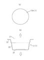
- FIG. 1 is a cross-sectional view of a metal laminate packaging material of the present invention
- FIG. (a) is a plan view of a molding blank that provides the molded container of the present invention.
- (b) is a cross-sectional view of a molded container obtained from the molding blank.
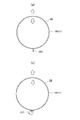
- (a) is a plan view of a body blank that provides the body of the combination container of the present invention.
- (b) is a perspective view of a trunk obtained from the trunk blank.
- (a) is a plan view of a bottom blank that provides the bottom of the combination container of the present invention;
- (b) is a perspective view of a bottom formed from the bottom blank.
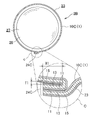
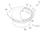
- 1 is a perspective view of a combination container according to the invention; FIG. FIG.
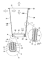
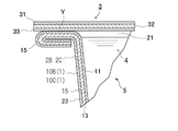
- FIG. 6 is a horizontal cross-sectional view showing an enlarged overlapping portion of the body of the combination container of FIG. 5;
- FIG. 6 is a vertical cross-sectional view along line V-V in the combination container of FIG. 5;
- the portion surrounded by the dashed line A is an enlarged view of the folding portion surrounded by the dashed line a.
- the portion surrounded by the dashed-dotted line B is an enlarged view of the overlapping portion surrounded by the dashed-dotted line b.
- FIG. 6 is a vertical cross-sectional view showing part of a process for manufacturing the combination container of FIG. 5;
- FIG. 4 is a vertical cross-sectional view showing part of the process for manufacturing the combination container of the present invention;
- FIG. 10 is a top view of the combination container of FIG. 9; In the figure, the portion surrounded by the dashed-dotted line C is an enlarged view of the overlapping portion surrounded by the dashed-dotted line c in the combination container.
- FIG. 2 is a perspective view of a package having the molded container of the present invention as an element; 12 is a partial cross-sectional view of the package of FIG. 11; FIG. 1 is a partial cross-sectional view of a package having the combination container of the present invention as an element; FIG.
- “Inside” refers to the direction of the heat-sealable layer side of both sides of the metal laminate packaging material of the present invention, and the upward arrows in FIGS. can be regarded as the direction of Further, the same direction is, for example, the upward arrow direction in FIG. 2(b), the right arrow direction in FIG. 5, the upward arrow direction in FIG.
- the arrow direction means the downward arrow direction in FIG.
- Outside refers to the opposite side of the heat-sealable layer on both sides of the metal laminate packaging material of the present invention, and each of FIGS. It can be regarded as the direction of the down arrow. Further, the same direction is, for example, the downward arrow direction in FIG. 2(b), the left arrow direction in FIG. 5, the downward arrow direction in FIG. 6, the leftward direction in FIG. The arrow direction means the upward arrow direction in FIG.
- Upward refers to the direction of the opening side of the container of the present invention with respect to the center of the body of the container, for example, the direction of the upward arrow in FIG.
- Bottom refers to the side opposite to the opening of the container of the present invention, that is, the direction toward the bottom, with the center of the body of the container of the present invention as a reference, for example, the direction of the downward arrow in FIG.
- Biomass refers to renewable, biologically derived organic resources. Biomass can be classified into waste biomass, unused biomass, and resource crops according to its state of existence. Waste biomass includes, for example, waste paper and wood from construction. Unused biomass includes, for example, various straws and forest residues. Examples of resource crops include carbohydrate resources such as sugarcane, starch resources such as corn, and oil resources such as rapeseed.
- Biomass-derived resin refers to a resin synthesized using raw materials derived from the biomass (hereinafter sometimes identified as bio-).
- “Fossil resource-derived resin” refers to resin synthesized using only raw materials derived from fossil resources (hereinafter sometimes identified as fuel-), and is distinguished from biomass-derived resin.
- Resins include one or both of biomass-derived resins and fossil resource-derived resins.
- Suitable biomass-derived resins include at least one selected from the group consisting of biomass-derived polyolefins (bio-polyolefins), biomass-derived polyesters (bio-polyesters), and biomass-derived polyamides (bio-polyamides).
- Biomass-derived polyolefins are polymers obtained from biomass-derived olefins (bio-olefins).
- Bio-olefins can be obtained by olefinizing bio-alcohols (bio-ethanol, bio-isopropanol, bio-butanol, etc.) obtained from sugar resources among the above-mentioned biomass by various known methods, and bio-ethylene, bio-propylene and bio-butene can be obtained.
- bio-olefins and olefins derived from fossil resources fuel-olefins
- composition ratio of bio-olefins and fuel-olefins in biomass-derived polyolefins is not particularly limited as long as bio-olefins are 10% by mass or more in all olefins, and is determined taking economic efficiency into account.
- the bio-olefin/fuel-olefin mass ratio is, for example, about 10/90 to 50/50, more preferably about 20/80 to 30/70.
- biomass-derived polyolefins include biomass-derived polyethylene (bio-PE), biomass-derived ethylene-propylene random copolymer (bio-rPP), biomass-derived ethylene-propylene block copolymer (bio-bPP), and biomass-derived homopolypropylene ( bio-hPP) and the like.
- bio-PE biomass-derived polyethylene
- bio-rPP biomass-derived ethylene-propylene random copolymer
- bio-bPP biomass-derived ethylene-propylene block copolymer
- bio-hPP biomass-derived homopolypropylene
- Biomass-derived polyesters are polymers obtained from raw materials such as lactones, polyols, polycarboxylic acids and hydroxycarboxylic acids.
- the raw material may be wholly derived from biomass, or may be a combination of a biomass-derived raw material and a fossil resource-derived raw material.
- Lactones include ⁇ -butyrolactone, ⁇ -valerolactone, ⁇ -caprolactone and the like.
- polyols examples include aliphatic, alicyclic and aromatic diols such as ethylene glycol, propylene glycol, butanediol, neopentyl glycol, diethylene glycol, polyethylene glycol, cyclohexanedimethanol, bisphenol A and bisphenol A-alkylene oxide adducts, and tri- to tetraols such as glycerin, trimethylolpurpan, trimethylolethane, pentaerythritol, diglycerin, ditrimethylolpropane and ditrimethylolethane.
- diols such as ethylene glycol, propylene glycol, butanediol, neopentyl glycol, diethylene glycol, polyethylene glycol, cyclohexanedimethanol, bisphenol A and bisphenol A-alkylene oxide adducts
- tri- to tetraols such as glycerin, trimethylo
- polycarboxylic acids examples include terephthalic acid, isophthalic acid, naphthalenedicarboxylic acid, cyclohexanedicarboxylic acid, adipic acid, azelaic acid, sebacic acid, maleic acid, maleic anhydride and fumaric acid.
- examples include dicarboxylic acids, and tri- to tetracarboxylic acids such as trimellitic acid, trimellitic anhydride, pyromellitic acid and pyromellitic anhydride.
- Hydroxycarboxylic acids include, for example, p-hydroxybenzoic acid, p-hydroxyethoxybenzoic acid, citric acid, malic acid and tartaric acid.
- biomass-derived polyesters include biomass-derived polyethylene terephthalate (bio-PET) and biomass trimethylene terephthalate (bio-PTT).
- bio-PET biomass-derived polyethylene terephthalate
- bio-PTT biomass trimethylene terephthalate
- Ethylene glycol (EG) of biomass PET can be made from sugar resource-derived bioethanol among the biomass, and terephthalic acid (TPA) is also made from such sugar resource-derived paraxylene (PX) as a raw material.
- PX sugar resource-derived paraxylene
- Biomass-derived polyamides are polymers obtained from raw materials such as lactones, diamines and dicarboxylic acids.
- the raw materials for the polyamide may all be derived from biomass, or may be a combination of raw materials derived from biomass and raw materials derived from fossil resources.
- Biomass-derived polyamides include n-nylon, which is a polycondensation reaction product of ⁇ -amino acids, and n,m-nylon, which is a co-condensation reaction product of diamines and dicarboxylic acids.
- n and m indicate the number of carbon atoms in the monomer component.
- Examples of n-nylon include nylon 6, 11, 12 and the like.
- n,m-nylon examples include nylon 66, 410, 510, 56, 610, 1012, 6T, 6I and 10T.
- Lactones include, for example, ⁇ -caprolactam, undecanelactam and lauryllactam.
- Diamines include, for example, hexamethylenediamine.
- dicarboxylic acids include adipic acid, sebacic acid, terephthalic acid and isophthalic acid.
- biomass-derived resins include polycarbonate, phenol resin, and cellulose acetate resin.
- suitable fossil resource-derived resins include fossil resource-derived polyolefin (fuel-polyolefin), fossil resource-derived polyester (fuel-polyester), and fossil resource-derived polyamide (fuel-polyamide).
- Fossil resource-derived polyolefins are polymers obtained only from olefins derived from fossil resources (fuel-olefins).
- Specific examples of fossil resource-derived polyolefins include fossil resource-derived polyethylene (fuel-PE), fossil resource-derived ethylene-propylene random copolymer (fuel-rPP), fossil resource-derived ethylene-propylene block copolymer (fuel-bPP), and fossil resource-derived polyolefins.
- At least one polyolefin selected from the group consisting of resource-derived homopolypropylene (fuel-hPP) and the like can be mentioned.
- Fossil-derived polyolefins are available in low, medium and high density types and may be modified with unsaturated dicarboxylic acids such as (anhydrous) maleic acid.
- Fossil resource-derived polyesters are polymers obtained from raw materials such as lactones, polyols, polycarboxylic acids and hydroxycarboxylic acids.
- all of the raw materials are derived from fossil resource-derived raw materials.
- Lactones include ⁇ -butyrolactone, ⁇ -valerolactone, ⁇ -caprolactone and the like.
- polyols examples include aliphatic, alicyclic and aromatic diols such as ethylene glycol, propylene glycol, butanediol, neopentyl glycol, diethylene glycol, polyethylene glycol, cyclohexanedimethanol, bisphenol A and bisphenol A-alkylene oxide adducts, and tri- to tetraols such as glycerin, trimethylolpurpan, trimethylolethane, pentaerythritol, diglycerin, ditrimethylolpropane and ditrimethylolethane.
- diols such as ethylene glycol, propylene glycol, butanediol, neopentyl glycol, diethylene glycol, polyethylene glycol, cyclohexanedimethanol, bisphenol A and bisphenol A-alkylene oxide adducts
- tri- to tetraols such as glycerin, trimethylo
- polycarboxylic acids examples include terephthalic acid, isophthalic acid, naphthalenedicarboxylic acid, cyclohexanedicarboxylic acid, adipic acid, azelaic acid, sebacic acid, maleic acid, maleic anhydride and fumaric acid.
- examples include dicarboxylic acids, and tri- to tetracarboxylic acids such as trimellitic acid, trimellitic anhydride, pyromellitic acid and pyromellitic anhydride.
- Hydroxycarboxylic acids include, for example, p-hydroxybenzoic acid, p-hydroxyethoxybenzoic acid, citric acid, malic acid and tartaric acid.
- Specific examples of fossil resource-derived polyesters include fossil resource-derived polyethylene terephthalate (fuel-PET) and fossil resource-derived trimethylene terephthalate (fuel-PTT). Terephthalate (fuel-PET) is preferred.
- Polyamides derived from fossil resources are polymers obtained from raw materials such as lactones, diamines and dicarboxylic acids.
- All of the raw materials are derived from fossil resources.
- Polyamides derived from fossil resources include n-nylon, which is a polycondensation reaction product of ⁇ -amino acids, and n,m-nylon, which is a co-condensation reaction product of diamines and dicarboxylic acids.
- n and m indicate the number of carbon atoms in the monomer component.
- Examples of n-nylon include nylon 6, 11, 12 and the like.
- Examples of n,m-nylon include nylon 66, 410, 510, 56, 610, 1012, 6T, 6I and 10T.
- Lactones include, for example, ⁇ -caprolactam, undecanelactam and lauryllactam.
- Diamines include, for example, hexamethylenediamine.
- dicarboxylic acids include adipic acid, sebacic acid, terephthalic acid and isophthalic acid.
- Examples of other fossil resource-derived resins include fossil resource-derived polycarbonates and fossil resource-derived phenolic resins.
- the biomass-derived resin and/or the fossil resource-derived resin may be combined with various elastomers, tackifiers, waxes, pigments, and the like as auxiliary materials.
- elastomers include polystyrene-based elastomers and polyolefin-based elastomers.
- the elastomer may be biomass-derived, fossil resource-derived, or a combination of both.
- the tackifying resin include rosins such as rosin, disproportionated rosin, hydrogenated rosin and polymerized rosin, derivatives thereof (alcohol esters and the like), and the like.
- wax include polyethylene wax, polypropylene wax and amide wax.
- Pigments include titanium oxide, zinc white, gloss white, palite, barium carbonate, calcium carbonate, precipitated silica, aerosil, talc, alumina white, mica, synthetic calcium silicate, magnesium carbonate, barium carbonate, carbon black, magnetite and Bengara and the like can be mentioned.
- the objects of the present invention are a metal laminate packaging material (1) (hereinafter sometimes abbreviated as packaging material (1)), a container (2), and a package (5).
- the container (2) is an article obtained by processing the packaging material (1). ) and a bottom portion (27) surrounded by a lower peripheral edge of the bottom portion (27).
- the "cylindrical" representing the shape of the body (23) refers to a hollow shape with both ends open and surrounded by walls. is not particularly limited.
- the term “cylindrical” includes both those having a constant cross-sectional shape and area in the length direction and those having a cross-sectional shape and/or area that change in the length direction.
- Examples of the container (2) in this specification include a molded container (2A), a combination container (2B), and a combination container (2C), which will be described later.
- the package (5) is a sealed body consisting of a container (2), a lid (3), and contents (4).
- the packaging material (1) is a laminated material comprising at least a thermal adhesive layer (11), a barrier layer (13) and a protective layer (15), and does not have a paper layer.
- the heat-sealable layer (11) is laminated inside the barrier layer (13) and is made of a heat-sealable resin.
- the heat-sealable layer (11) may be a single layer or multiple layers.
- the multilayer heat sealing layer (11) is composed of at least two independent layers.
- the two-layer heat sealing layer (11) consists of a single outermost heat sealing layer (11a) and a single innermost heat sealing layer (11c).
- the three or more heat sealing layers (11) consist of a single outermost heat sealing layer (11a), a single or multiple intermediate heat sealing layer (11b), and a single innermost heat sealing layer. It consists of a layer (11c).
- An adhesive layer (12) may be interposed between the thermal adhesive layer (11) and the barrier layer (13).
- An adhesive layer (14) may also be interposed between the barrier layer (13) and the protective layer (15).
- the protective layer (15) is laminated inside the barrier layer (13) and is made of film-like synthetic resin.
- the protective layer (15) may be a single layer or multiple layers.
- the multilayer protective layer (15) consists of at least two independent layers.
- the two-layered protective layer (15) consists of a single outermost heat sealing layer (15a) and a single innermost heat sealing layer (15c).
- the three or more protective layers (15) consist of a single outermost heat sealing layer (15a), a single or multiple intermediate heat sealing layer (15b), and a single innermost heat sealing layer. Consists of (15c).
- FIG. 1 illustrates a specific form of the packaging material (1) of the present invention.
- the packaging material (1) in FIG. 1(a) is the first embodiment.
- the same form consists of a heat-sealable layer (11), an adhesive layer (12) (optional), a barrier layer (13), an adhesive layer (14) (optional) and a protective layer (15) in order from the inside.
- the packaging material (1) in FIGS. 1(b), 1(c) and 1(d) is a modification of the first embodiment.
- the packaging material (1) in FIG. 1(b) is the second embodiment.
- only the heat sealing layer (11) is a multilayer, and from the inside, the outermost heat sealing layer (11a), the middle heat sealing layer (11b) and the innermost heat sealing layer (11c).
- the packaging material (1) in FIG. 1(c) is the third embodiment.
- only the protective layer (15) is a multi-layered structure consisting of an innermost protective layer (15a), an intermediate protective layer (15b) and an outermost protective layer (15c) in order from the inside.
- the packaging material (1) in FIG. 1(d) is the fourth embodiment.
- the heat sealing layer (11) consists of an outermost heat sealing layer (11a), an intermediate heat sealing layer (11b) and an innermost heat sealing layer (11c) in order from the inside
- a protective layer (15) consists of an innermost protective layer (15a), an intermediate protective layer (15b) and an outermost protective layer (15c) in order from the inside.
- the heat-fusible resin forming the heat-fusible layer (11) and/or the film-like synthetic resin forming the protective layer (15) contain a biomass-derived resin.
- Three modes are given below.
- Aspect 1 The heat-fusible resin forming the heat-fusible layer (11) contains a biomass-derived resin, and the synthetic resin forming the protective layer (15) does not contain a biomass-derived resin.
- Aspect 2 The heat-fusible resin forming the heat-fusible layer (11) contains a biomass-derived resin, and the synthetic resin forming the protective layer (15) also contains a biomass-derived resin.
- Aspect 3 The heat-fusible resin forming the heat-fusible layer (11) does not contain a biomass-derived resin, and the synthetic resin forming the protective layer (15) contains a biomass-derived resin.
- the thermal fusion layer (11) is conceived as a single layer or multiple layers.
- the heat-fusible layer (11), which is a single layer, is composed of a layer made of a heat-fusible resin, and the heat-fusible resin is composed of a biomass-derived resin and/or a fossil resource-derived resin.
- the heat sealing layer (11), which is a single layer is composed of a biomass-derived resin.
- the thickness of the heat-sealable layer (11), which is a single layer is not limited, and is, for example, 25 ⁇ m to 500 ⁇ m in consideration of heat sealability.
- the thickness is preferably 30 ⁇ m to 400 ⁇ m from the viewpoint of optimizing heat-sealing property and content resistance.
- the thermal adhesive layer (11), which is a multilayer, is composed of two or more independent layers made of a thermal adhesive resin, and the thermal adhesive resin is composed of a biomass-derived resin and/or a fossil resource-derived resin. do.
- the protective layer (15) does not contain a biomass-derived resin layer
- the multi-layer heat-sealable layer (11) contains a layer made of a biomass-derived resin.
- the multilayer heat sealing layer (11) is composed of an outermost heat sealing layer (11a), an intermediate heat sealing layer (11b) and an innermost heat sealing layer (11c) in order from the inside.
- the intermediate heat sealing layer (11b) is optional and can be omitted.
- the outermost heat-sealable layer (11a), omitting the intermediate heat-sealable layer (11b) and the innermost heat-sealable layer (11c), can be regarded as a single heat-sealable layer (11).
- the total thickness of the heat-sealable layer (11), which is a multilayer, is not particularly limited, and in consideration of sealing properties, corrosion of the barrier layer (13) by the contents (4), etc., it is, for example, 25 ⁇ m to 500 ⁇ m, preferably 30 ⁇ m. ⁇ 400 ⁇ m.
- the outermost heat-sealable layer (11a) is a single layer forming the inner surface of the housing portion of the container (2) and the upper surface of the flange portion (22) of the container (2). Direct heat-sealing of the outermost heat-sealable layer (11a) and the heat-sealable layer forming the lower surface of the lid (3) realizes heat-sealing of the container (2).
- the thickness of the outermost heat sealing layer (11a) is not particularly limited, and is, for example, 2 ⁇ m to 100 ⁇ m, preferably 3 ⁇ m to 60 ⁇ m.
- the intermediate heat-fusible layer (11b) can be defined as the layer remaining after removing the outermost heat-fusible layer (11a) and the innermost heat-fusible layer (11c) from the multilayer heat-fusible layer (11). , may be a single layer or multiple layers.
- the intermediate heat-sealable layer (11b) indirectly performs heat-sealing between the outermost heat-sealable layer (11a) and the heat-sealable layer forming the lower surface of the lid (3). It acts as a bonding layer between (11a) and the innermost heat sealing layer (11c), and also functions as a reinforcing layer that enhances the strength of the entire heat sealing layer (11).
- the number of intermediate heat-sealable layers (11b) is not particularly limited, and is, for example, 1-7.
- the total thickness of the intermediate heat-sealing layer (11b) is not particularly limited, and is, for example, 15 ⁇ m to 160 ⁇ m, preferably 20 ⁇ m to 64 ⁇ m.
- the innermost heat-fusible layer (11c) is the innermost single layer of the multilayer heat-fusible layer (11), and the multilayer heat-fusible layer (11) and the printing ink layer (optional) and/or responsible for bonding with the barrier layer (13).
- the thickness of the innermost heat sealing layer (11c) is not particularly limited, and is, for example, 2 ⁇ m to 100 ⁇ m, preferably 3 ⁇ m to 60 ⁇ m.
- the outermost heat sealing layer (11a), the middle heat sealing layer (11b) (optional), and the innermost heat sealing layer (11c) are all made of biomass-derived resin.
- some layers may be composed of a biomass-derived resin and other layers may be composed of a fossil resource-derived resin.
- the intermediate heat-sealing layer (11b) has a multi-layer structure, some layers can be made of biomass-derived resin and other layers can be made of fossil resource-derived resin.
- the stacking order of the biomass-derived resin layer and the fossil resource-derived resin layer is arbitrary and not particularly limited.
- the polyolefin those already mentioned can be used, and at least one selected from the group consisting of biomass-derived polyethylene, biomass-derived ethylene-propylene random copolymer and biomass-derived ethylene-propylene block copolymer is particularly preferable.
- the already mentioned fossil resource-derived polyolefin can be mentioned.
- the polyolefin those already mentioned can be used, and at least one selected from the group consisting of fossil resource-derived polyethylene, fossil resource-derived ethylene-propylene random copolymer and fossil resource-derived ethylene-propylene block copolymer is particularly preferable.
- the heat-sealable layer (11), which is a multilayer, can be formed by various known methods such as dry lamination, melt extrusion lamination, heat lamination, and gravure coating. These methods may be combined.
- the adhesive layer (12) By interposing the adhesive layer (12) between the thermal adhesive layer (11) and the barrier layer (13), delamination between the two layers can be prevented when the packaging material (1) is processed.
- adhesives constituting the adhesive layer (12) include vinyl chloride-vinyl acetate copolymer adhesives, polyester adhesives, epoxy adhesives, polyolefin adhesives, and polyurethane adhesives. Polyurethane resin-based adhesives are preferred.
- the polyurethane resin adhesive a two-component curable polyurethane resin adhesive is preferable, and a two-component curable polyether urethane resin-based adhesive and/or a two-component curable polyester urethane resin-based adhesive is particularly preferable.
- the adhesive may also be one using a biomass-derived raw material.
- the thickness of the adhesive layer (12) is not particularly limited, and is, for example, 1 ⁇ m to 8 ⁇ m, preferably 2 ⁇ m to 6 ⁇ m, from the viewpoint of preventing delamination.
- the barrier layer (13) is a layer for protecting the contents (4) of the package (5) from gas, water vapor, light, etc., and is made of metal foil.
- the metal foil examples include aluminum foil, iron foil, stainless steel foil, copper foil, nickel foil, and the like, and aluminum foil is preferable in consideration of barrier function, formability, cost, and the like.
- the aluminum foil examples include pure aluminum foil and aluminum alloy foil, and a soft material (O material) is preferable.
- A1000 series or A8000 series aluminum foil specified by JIS H4160 is suitable. It is preferable in terms of moldability, and can prevent delamination during molding and prevent unevenness in molding height.
- the A8079-H material or A8021-H material which are hard materials, is used, the overall strength of the container (2), especially the strength of the flange (22), is increased, so that the flange (22) may be damaged by an unexpected impact. ) can be suppressed. Also, the shape retention of the entire container (2) is improved.
- a base layer (not shown) made of a predetermined chemical conversion treatment solution can be formed on the inner surface and/or the inner surface of the metal foil.
- the chemical conversion treatment solution include a water-alcohol solution containing phosphoric acid, a chromium-based compound, a fluorine-based compound and/or a binder resin.
- the amount of the chemical conversion treatment solution used is not particularly limited, as long as the amount of chromium adhered per side of the metal foil is, for example, 0.1 mg/m 2 to 50 mg/m 2 , preferably 2 mg/m 2 to 20 mg/m 2 . Just do it.
- the thickness of the barrier layer (13) is not particularly limited. It can be determined in consideration of shape retention and the like, and is, for example, 40 ⁇ m to 200 ⁇ m, preferably 80 ⁇ m to 160 ⁇ m.
- the amount of metal foil used in the packaging material (1) is not particularly limited, but considering the desired barrier function of the barrier layer (13) and the recyclability of the metal foil, the unit area of the packaging material (1)
- the amount used per unit is 50% to 90%, preferably 65% to 85%, more preferably 55% to 80%, based on mass.
- the "mass standard” means the mass ratio of the metal foil per unit area to the mass per unit area of the packaging material (1).
- the adhesive layer (14) By interposing the adhesive layer (14) between the barrier layer (13) and the protective layer (15), delamination between the two layers can be prevented when the packaging material (1) is processed.
- the adhesive that forms the adhesive layer (14) the adhesive that forms the adhesive layer (12) can be used, and a two-part curable polyurethane adhesive is particularly suitable.
- the thickness of the adhesive layer (14) is not particularly limited, and is 1 ⁇ m to 8 ⁇ m, preferably 2 ⁇ m to 6 ⁇ m, considering the delamination preventive effect.
- the printing ink is a composition obtained by dispersing a coloring material such as a pigment or a dye in a vehicle containing a binder resin and an organic solvent, and various known inks can be used without particular limitation.
- the protective layer (15) is conceived as a single layer or multiple layers.
- the protective layer (15), which is a single layer, is composed of a film-like synthetic resin layer, and the synthetic resin is composed of a biomass-derived resin and/or a fossil resource-derived resin.
- the protective layer (15), which is a single layer is made of a biomass-derived resin.
- the thickness of the protective layer (15), which is a single layer is not particularly limited. , for example 15 ⁇ m to 200 ⁇ m, preferably 20 ⁇ m to 60 ⁇ m.
- the multilayer protective layer (15) is composed of two or more independent film-like synthetic resin layers, and the synthetic resin is composed of a biomass-derived resin and/or a fossil resource-derived resin.
- the multilayer protective layer (15) contains a layer made of a biomass-derived resin.
- the multilayer protective layer (15) is composed of an innermost protective layer (15a), an intermediate protective layer (15b) and an outermost protective layer (15c) in order from the inside.
- the intermediate protective layer (15b) is optional and can be omitted.
- the remaining innermost protective layer (15a), omitting the intermediate protective layer (15b) and the innermost protective layer (15c), can be regarded as a single-layer protective layer (15).
- the overall thickness of the multilayer protective layer (15) is not particularly limited, and is, for example, 15 ⁇ m to 200 ⁇ m, preferably 20 ⁇ m to 60 ⁇ m in consideration of corrosion resistance and the like.
- the innermost protective layer (15a) is a layer that joins the barrier layer (13) or adhesive layer (14) and the protective layer (15).
- the thickness of the innermost protective layer (15a) is not particularly limited, and is, for example, 2 ⁇ m to 100 ⁇ m, preferably 3 ⁇ m to 60 ⁇ m.
- the intermediate protective layer (15b) is defined as the layers remaining after removing the innermost protective layer (15a), which is a single layer, and the outermost protective layer (15c), which is also a single layer, from the multilayer protective layer (15). can.
- the intermediate protective layer (15b) is a single layer or multiple layers.
- the intermediate protective layer (15b) acts as a bonding layer between the innermost protective layer (15a) and the outermost protective layer (15c), and also functions as a reinforcing layer that increases the strength of the protective layer (15) as a whole.
- the number of layers of the intermediate protective layer (15b) is not particularly limited, and is, for example, 1-4.
- the total thickness of the intermediate protective layer (15b) is not particularly limited, and is, for example, 15 ⁇ m to 160 ⁇ m, preferably 20 ⁇ m to 64 ⁇ m.
- the outermost protective layer (15c) is a layer that constitutes the outermost surfaces of the molded container (2) and the package (5), and directly serves to protect them from the impact of dropping and the force applied from the outside. Fulfill.
- the thickness of the outermost protective layer (15c) is not particularly limited, and is, for example, 2 ⁇ m to 100 ⁇ m, preferably 3 ⁇ m to 60 ⁇ m.
- the innermost protective layer (15a), the intermediate protective layer (15b) (optional), and the outermost protective layer (15c) may all be made of biomass-derived resin.
- a part layer may be composed of a biomass-derived resin, and other layers may be composed of a fossil resource-derived resin.
- the intermediate protective layer (15b) is multi-layered, some layers can be made of biomass-derived resin and other layers can be made of fossil resource-derived resin.
- the stacking order of the biomass-derived resin layer and the fossil resource-derived resin layer is arbitrary and is not particularly limited.
- biomass-derived resin that can constitute the protective layer (15) examples include the biomass-derived polyester and/or biomass-derived polyolefin already described.
- polyester those already mentioned can be used.
- polyolefin those already mentioned can be used, and in particular, at least one selected from the group consisting of biomass-derived polyethylene, biomass-derived ethylene-propylene random copolymer and biomass-derived ethylene-propylene block copolymer is preferable.
- Examples of the fossil resource-derived resin that can constitute the protective layer (15) include the already mentioned fossil resource-derived polyester and/or fossil resource-derived polyolefin.
- As the polyester those already mentioned can be used.
- the polyolefin is preferably at least one selected from the group consisting of fossil resource-derived polyethylene, fossil resource-derived ethylene-propylene random copolymer, and fossil resource-derived ethylene-propylene block copolymer.
- the film-like synthetic resin that forms the protective layer (15) may have heat-sealing properties regardless of whether the layer (15) is single-layered or multi-layered.
- the packaging material (1) in which the protective layer (15) is made of a heat-sealable film-like synthetic resin is useful in the case of producing combination containers (2B) and (2C) described later among the containers (2). is.
- the multilayer protective layer (15) can be formed by various known methods such as dry lamination, melt extrusion lamination, heat lamination, and gravure coating. These methods may be combined.
- the protective layer (15) behaves as follows during the molding process of the packaging material (1). That is, for example, when a circular molding blank (10A) made of the packaging material (1) is subjected to press working, particularly deep drawing, in order to produce a molded container (2A) described later, the blank (10A) is Of the region to be molded, the portion corresponding to the flange portion (22) of the molded container (2A) is compressed, while the portion corresponding to the body portion (23) is stretched. In particular, the portion corresponding to the rounded portion forming the boundary between the trunk portion (23) and the bottom portion (27) is further stretched.
- the film-like synthetic resin forming the entire protective layer (15) preferably has the following characteristic configuration 1.
- Characteristic structure 1 Tensile modulus of elasticity ( ⁇ 1 (MD) ) in the machine direction (MD) of the film-like synthetic resin is limited to 500 MPa to 2500 MPa (preferably 500 MPa to 1000 MPa), and tensile elasticity in the width direction (TD)
- the ratio ( ⁇ 1 (TD) ) is also limited to 500 MPa to 2500 MPa (preferably 500 MPa to 1000 MPa), and the ratio of both tensile strengths ( ⁇ 1 (MD) / ⁇ 1 (TD) ) is 0.9 to 1.1 (preferably is limited to 0.95 to 1.05).
- the entire protective layer (11) is composed of a film-like synthetic resin having characteristic structure 1, the formability of the packaging material (1) is improved. Delamination with the layer (13) can be prevented. In addition, it becomes easy to secure the molding height of the molded container (2A) made of the same packaging material (1) and the bottom portion (27) described later.
- the film-like synthetic resin forming the protective layer (15) is further provided with characteristic configuration 2 and/or characteristic configuration 3 below.
- Characteristic configuration 2 The tensile strength ( ⁇ 2 (MD) ) at break in the machine direction (MD) of the film-like synthetic resin is limited to 30 MPa to 70 MPa (preferably 30 MPa to 50 MPa), and in the width direction (TD) The tensile strength at break ( ⁇ 2 (TD) ) is also limited to 30 MPa to 70 MPa (preferably 30 MPa to 50 MPa), and their ratio ( ⁇ 2 (MD) / ⁇ 2 (TD) ) is 0.9 to 1.1. (preferably 0.95 to 1.05).
- Characteristic configuration 3 The tensile elongation (E (MD) ) at break in the machine direction (MD) of the film-like synthetic resin is limited to 500% to 900% (preferably 500% to 800%), and the width direction (TD ) at break (E (TD) ) is also limited to 500% to 900% (preferably 500% to 800%), and their ratio (E (MD) /E (TD) ) is 0.8 ⁇ 1.2 (preferably 0.9-1.1).
- the film-like synthetic resin forming the protective layer (15) has all of the characteristic configurations 1, 2 and 3.
- characteristic configurations 1, 2 and 3 are measured values according to JIS K 7161 and JIS K 7127 ("Testing methods for plastic tensile properties").
- the packaging material (1) can be manufactured by various known methods such as dry lamination, melt extrusion lamination, heat lamination, etc. These methods may be combined.
- the container (2) has at least an opening (21), a body (23), and a bottom (27), as described above.
- the container (2) includes the molded container (2A) and the combination container (2B) and combination container (2C). They will be explained in order below.
- the molded container (2A) is an article formed by molding a molding blank (10A) made of the packaging material (1), and has an opening (21). In addition, it is an integrated container in which the body (23) and the bottom (27) are continuous. A flange portion (22) may be formed along the periphery of the opening (21).
- FIG. 2(a) is one form of a molding blank (10A).
- the shape is not particularly limited, and may be a circle as shown in the figure, or a polygonal shape such as a rectangle (not shown).
- the molding blank (10A) is not essential.
- the packaging material (1) of unspecified shape is molded as it is to produce a molded container (2A)
- the forming blank (10A) can be disregarded.
- the forming processing means is not particularly limited, and examples thereof include deep drawing and stretch forming.
- FIG. 2(b) is a cross-sectional view of the molded container (2A).
- the molded container (2A) is cup-shaped, and a brim-shaped flange (22) is formed around the periphery of the opening (21).
- the size and shape of the flange portion (22) are not particularly limited, and are determined appropriately as long as the lid (3) can be heat-sealed on the upper surface thereof and the package (5) can be sealed after heat-sealing. can.
- the flange portion (22) may have an annular shape, or, although not shown, may have a polygonal annular shape.
- a step is formed in the middle of the height of the body (23) of the molded container (2A), and a convex portion is provided on the bottom (27), but these configurations are arbitrary. . Such an optional configuration can enhance the mechanical strength and stackability of the molded container (2A).
- Both combination containers (2B) and (2C) are combined containers having a cylindrical body (23) and a bottom (27) joined to the lower peripheral edge of the body (23). .
- a brim-shaped flange (22) may be formed on the periphery of the opening (21).
- FIG. 3(a) is a plan view of the trunk blank (10B) that provides the trunk (23).
- the blank (10B) is fan-shaped, but this is an example, and the shape can be set according to the shape of the combination container (2B).
- FIG. 3(b) is a perspective view of the trunk (23) obtained from the trunk blank (10B).
- the trunk portion (23) is a tapered cylindrical member, and is formed by overlapping and joining both end edges of the fan-shaped trunk blank (10B). Therefore, the trunk (23) has an overlapping portion (24B) extending along its height direction.
- FIG. 4(a) is a plan view of the bottom blank (10C) that provides the bottom (27).
- the blank (10C) has a circular shape, but this is an example, and the shape can be set according to the shape of the combination container (2B).
- FIG. 4(b) is a perspective view of the bottom (27) obtained from the bottom blank (10C).
- the bottom portion (27) is, for example, a member with a substantially inverted U-shaped cross section formed by deep drawing a circular bottom blank (10C), and is composed of a circular and horizontal body portion (28) and the body portion (28). and a hanging portion (29) extending upward from the outer peripheral edge.
- Fig. 5 is a perspective view of the combination container (2B).
- the container (2B) is cup-shaped, and is integrally joined by sealing the body (23) and the bottom (27).
- FIG. 6 is a cross-sectional view of the overlapping portion (24B) of the body portion (23).
- the overlap portion (24B) is formed by overlapping one edge portion and the other edge portion of the fan-shaped trunk blank (10B).
- Total thickness (T1) of overlapping of the protective layer (15) on one edge of the body blank (10B) and the heat-sealable layer (11) on the other edge in the overlapping portion (24B) is not particularly limited, and is, for example, 55 ⁇ m to 195 ⁇ m.
- the thickness (T1) is preferably 60 ⁇ m to 190 ⁇ m.
- the width (W1) of the overlapping portion (24B) is also not particularly limited, and is, for example, 2 mm to 10 mm. By setting the same width (W1) to 2 mm or more, it is possible to sufficiently secure the barrier property and sealing property of the overlapping portion (24B). Also, by setting the overlapping width (W1) to less than 10 mm, it is possible to reduce costs and prevent wrinkles in the overlapping portion (24B). From the above point of view, the same width (W1) is preferably 4 mm to 8 mm.
- FIG. 7 is a cross-sectional view of the combination container (2B).
- the portion surrounded by the dashed-dotted line A on the outer side of the body (23) is an enlarged view of the overlapping portion (24B) surrounded by the dashed-dotted line b.
- an outwardly bent flange portion (22) is provided at the edge of the opening (21) on the upper end side of the body portion (23).
- the flange portion (22) is optional, and may have a form other than that shown. For example, it may be formed in a flat shape folded in three, or may be curled downward and formed into a generally arcuate cross section.
- the lower edge of the body (23) is formed with an inwardly folded folded portion (25) as indicated by the portion surrounded by the dashed line b.
- An enlarged view of the folded portion (25) is shown by a portion surrounded by a dashed line B. As shown in FIG.
- a trunk blank (10B) and a bottom blank (10C) are produced.
- the trunk blank (10B) is obtained, for example, by punching the packaging material (1) into a fan shape of a predetermined size, as shown in FIG. 3(a).
- the bottom blank (10C) is obtained, for example, by punching out a circle of predetermined size from the packaging material (1), as shown in FIG. 4(a).
- the packaging material (1) constituting the trunk blank (10B) and the packaging material (1) constituting the bottom blank (10C) are usually the same, but differ in material and/or thickness. You can let
- the bottom part (27), for example, as shown in FIG. 4(b), is obtained by deep drawing a circular bottom part blank (10C) using a die (not shown).
- the bottom part (27) in the figure is a component with an inverted U-shaped cross section, consisting of a circular horizontal body part (28) and a hanging part (29) rising from the periphery of the body part (28).
- the bottom part (27) is preferably manufactured so that the surface of the hanging part (28) in particular is not wrinkled. By suppressing wrinkles, the bottom part (27) and the body part (23) can be easily joined integrally, and leakage can be prevented even when the liquid content (4) is stored in the combination container (2B).
- the corner portion between the body portion (28) and the drooping portion (29) on the outer surface of the bottom portion (27) has a substantially right-angled cross section, but may be rounded.
- the bottom (27) and the body blank (10B) are joined. Specifically, after setting the bottom part (27) on the top surface of a mold (not shown) having a substantially truncated cone shape so that the upper surface of the main body part (28) overlaps, the outer periphery of the mold is After wrapping the body blank (10B) around the surface and overlapping the both edges, the heat-sealing layer (11) and the protective layer ( 15) is heat-sealed to form a tapered tubular body (23).
- FIG. 8 shows the process of forming the flange portion (22) and the folded portion (25).
- the flange portion (22) is formed by curling the upper edge of the body portion (23) outward using a predetermined curling mold (not shown) at the horizontal position of the opening (21) indicated by the two-dot chain line. , pressurized in the vertical direction to form a substantially horizontal two-fold flat shape.
- the folded portion (25) is a portion that assists the joining of the body portion (23) and the bottom portion (27), and the joining is performed by heat sealing.
- the heat-sealing is performed between the heat-sealing layer (11) at the lower end (26) of the trunk (23) and the protective layer (15) of the drooping portion (29) of the bottom (27), as well as on the same bottom. It is realized between the heat-sealing layer (11) of (27) and the heat-sealing layer (11) of the folded portion (25).
- the folded portion (25) is optional. In this case, after fitting the cup-shaped bottom (27) to the lower edge of the body (23), the protective layer (15) of the bottom (27) and the body (23) are separated. Thermal bonding is achieved with the thermal bonding layer (11).
- the heat-sealing means is not particularly limited, and examples thereof include heat-sealing using a hot plate, high-frequency sealing, and ultrasonic sealing.
- the heat-sealing conditions are not particularly limited. It can be set as appropriate. Examples are given below.
- the melting point of the heat-fusible resin forming the heat-fusible layer (11) and the film-like synthetic resin (heat-fusible resin) forming the protective layer (15) It is preferable to heat-seal by pressing a hot plate set to a temperature about 20 to 40° C. higher than both of the melting points of the trunk blank (10B) from both sides of both edges.
- the melting point is generally about 160 to 170°C, so the heat sealing temperature is 160 to 170°C. It should be about 220°C.
- both the heat-sealing layer (11) and the protective layer (15) are made of polyethylene (PE), the melting point is generally about 115-135°C. Just do it. As other conditions, the load should be about 80 to 200 kgf, and the sealing time should be about 1 to 5 seconds.
- PE polyethylene
- the conditions are not particularly limited, but for example, output: 0.5 to 1.5 kW, sealing time: 3 to 5 seconds, distance from coil: 0.5 to 15 mm, load: 100 to 200 kgf.
- the lower end part (26) of the body part (23) is folded inward to form a folded part (25).
- the folded portion (25) is pressed against the hanging portion (29) of the bottom portion (27) by a disk-shaped rotary mold (not shown).
- the lower end of the body (23), the folded part (25), and the hanging part (29) of the bottom (27) are heat-sealed to join the body (23) and the bottom (27) together.
- Join and integrate examples of heat-sealing means include heat sealing using a hot plate or the like, high-frequency sealing, ultrasonic sealing, and the like.
- the conditions described above can be adopted as the heat-sealing conditions.
- the folded portion (25) first and the flange portion (22) later.
- FIG. 9 is a top view of the body (23) forming the combination container (2C), showing a part of the manufacturing process of the container (2C).
- both end edges of the trunk blank (10C) forming the trunk portion (23) form a joint portion (24C), and the joint portion (24C) is It extends in the height direction of the combination container (2C).
- heat sealing is performed between the heat sealing layer (11) on one edge and the heat sealing layer (11) on the other edge. Realized.
- the palm-to-palm portion (24C) is joined to the outer surface of the trunk portion (23) by being bent to one side so as to overlap the side surface of the trunk portion (23).
- the joint between the palm-to-palm portion (24C) and the side surface of the body portion (23) can be performed by the heat-sealing means described above, and is preferably a high-frequency seal.
- Conditions for high-frequency sealing are not particularly limited, and for example, an output of 0.5 to 1.5 kW, a sealing time of 3 to 5 seconds, and a load of 100 to 200 kgf may be used.
- the distance between the coil of the high-frequency sealing device and the jointed portion (24C) may be 0.5 to 15 mm.
- Fig. 10 is a top view of the combination container (2C).
- the area surrounded by the dashed-dotted line C shows an enlarged view of the joint portion (24C) surrounded by the dashed-dotted line c.
- the inner protective layer (15) at the folded portion (25) of one end edge of the body blank (10B) in the joint portion (24C), and the inner heat sealing layer (11) at the folded portion (25). ) is not particularly limited, and is, for example, 55 ⁇ m to 195 ⁇ m.
- the thickness (T1) is preferably 60 ⁇ m to 190 ⁇ m.
- the width (W1) of the palm-joint part (24C) is also not particularly limited, and is, for example, 5 mm to 20 mm. By setting the same width (W1) to 5 mm or more, it is possible to sufficiently secure the barrier property and sealing property of the overlapping portion (24B). Also, by setting the overlapping width (W1) to less than 20 mm, it is possible to reduce costs and prevent wrinkles in the overlapping portion (24B). From the above point of view, the same width (W1) is preferably 10 mm to 18 mm.
- the shape of the combination containers (2B) and (2C) is not limited to the cup-like shape shown in FIG. It may be in the form of a small tray.
- the lid (3) is a heat-sealing material for the container (2). It is processed into a predetermined shape. An adhesive layer made of the adhesive may be interposed between the protective layer (31) and the barrier layer (32) and/or between the barrier layer (32) and the thermal adhesive layer (33). . As with the packaging material (1), the lid (3) also includes the protective layer (31) and/or the heat-sealable layer (33) partially or wholly made of a biomass-derived resin, thereby disposing of the package (5). Contributes to carbon neutralization during processing.
- the protective layer (31) is a layer in the lid (3) for protecting the package (5) and its contents (4) from external impacts, etc., and is made of various known synthetic resins. .
- synthetic resin among the biomass-derived resins and/or the fossil resource-derived resins, those that can be used as a protective layer can be appropriately used, and polyesters and/or polyolefins are preferable.
- polyester polyethylene terephthalate is preferred.
- Preferred polyolefins are polyethylene, polypropylene, ethylene-propylene copolymers (block, random) and homopolypropylene.
- the protective layer (31) may be composed of an overcoat agent such as nitrocellulose, shellac resin, epoxy resin, urethane resin, chlorinated polyolefin resin, acrylic resin, and vinyl chloride-vinyl acetate copolymer.
- the protective layer (31) may be a single layer or a multilayer consisting of at least two independent layers.
- the thickness of the protective layer (31) as a whole is not particularly limited, and is, for example, 3 ⁇ m to 100 ⁇ m.
- the barrier layer (32) has the function of protecting the contents (4) of the package (5) together with the container (2) from light, gas, water vapor and the like.
- the barrier layer (32) is made of metal foil, and the metal foil that constitutes the barrier layer (13) can be used.
- the metal foil an aluminum foil is particularly preferable, and a 1000 series O material or an 8000 series O material specified in JIS H4160 is suitable.
- a base layer made of the treatment liquid may be provided on one side or both sides of the metal foil.
- the thickness of the barrier layer (32) is not particularly limited, and is, for example, 15 ⁇ m to 200 ⁇ m.
- the heat-sealable layer (33) is a layer that is heat-sealed with the heat-sealable layer (11) forming the upper surface of the opening (21) periphery of the container (2), and is composed of various known heat-sealable resins. do.
- the biomass-derived resins and/or the fossil resource-derived resins those having heat-fusible properties can be appropriately used as the heat-fusible resin, and polyolefin is preferable. Suitable polyolefins are polyethylene, polypropylene, ethylene-propylene copolymers (block, random) and homopolypropylene.
- the heat-sealable layer (33) may be a single layer or at least two layers.
- the total thickness of the heat sealing layer (33) is not particularly limited, and is, for example, 10 ⁇ m to 50 ⁇ m.
- the lid material forming the lid (3) can be manufactured by various known methods such as dry lamination, melt extrusion lamination, heat lamination, and gravure coating.
- the shape and dimensions of the lid (3) are not particularly limited, and can be set according to the shape and dimensions of the opening (21) and the flange (22) of the container (2).
- the periphery of the lid (3) may be provided with an opening tab (34), as shown in FIG.
- Contents (4) include food, pharmaceuticals, chemical products, electronic parts, batteries, hygiene products, and other industrial products.
- foods include cream cheese, butter, jelly, yokan, pudding, miso, curry, pasta sauce, juice, and dressing.
- the shape of the content (4) is also not limited, and may be liquid, semi-solid, or solid.
- the package (5) is a sealed body obtained by heat-sealing the opening (21) of the container (2) with the lid (3) after containing the content (4) in the container (2).
- FIG. 11 is a perspective view of a package (5) composed of a lid (3), a molded container (2A), and contents (4). Part of (3) is omitted.
- the heat-sealing layer (33) of the lid (3) and the heat-sealing layer (11) of the flange (22) are heat-sealed to form an annular shape.
- a heat-sealed zone (Y) is formed, and the seal of the package (5) is realized at the heat-sealed zone (Y).
- An opening notch (X) (optional) is annularly formed in the upper surface of the flange portion (22) along the circumferential direction.
- FIG. 12 is a partial cross-sectional view of the package shown in FIG. 11.
- a heat-sealed zone (Y) is formed between the lid (3) and the flange (22), and the upper surface of the flange (22) is formed with an annular notch (X).
- Fig. 13 is a partial cross-sectional view of a package (5) having combination containers (2B) and (2C) as elements.
- a heat-sealed zone (Y) is formed between the lid (3) and the flange (22). Note that the annular notch (X) is omitted from the drawing.
- the depth of the opening notch (X) is not particularly limited. Just do it.
- the shape of the heat-sealing zone (Y) is not particularly limited, and may be, for example, an annular shape similar to the flange portion (22). Also, the dimensions are not particularly limited.
- the package (5) is used by peeling off the lid (3) from the flange (22) of the container (2). After the used package (5) is discarded, the container (2) is recovered, and metal foil is recycled from this, thereby contributing to resource recovery. In addition, since the container (2) uses a biomass-derived resin for the thermal adhesive layer (11) and/or the protective layer (15), the package (5) also contributes to carbon neutralization.
- rPP ethylene-propylene random copolymer
- bPP ethylene-propylene block copolymer
- CPP unstretched polypropylene
- Example 1 On both sides of 120 ⁇ m thick aluminum foil (A8021-O material: JIS H4160), chemical conversion treatment solution (solution consisting of phosphoric acid, polyacrylic acid, chromium (III) salt compound, water and alcohol) A treated aluminum foil was produced by coating so as to be 11 mg/m 2 per unit area and drying. Next, one side of the barrier layer made of this treated aluminum foil was coated with a two-liquid curing type polyester polyurethane adhesive and dried to form an adhesive layer with a thickness of 3 ⁇ m. Next, a 30 ⁇ m-thick biomass-derived polyethylene terephthalate (bio-PET) film (using biomass ethylene glycol) was adhered to the adhesive layer to form a protective layer.
- bio-PET biomass-derived polyethylene terephthalate
- Characteristic configuration 1 ⁇ 1 (MD) is 1500 MPa, ⁇ 1 (TD) is 1600 MPa, ⁇ 1 (MD) / ⁇ 1 (TD) 0.94
- Characteristic configuration 2 ⁇ 2 (MD) is 64 MPa, ⁇ 2 (TD) is 60 MPa, ⁇ 2 (MD) / ⁇ 2 (TD) is 1.07
- Feature configuration 3 E (MD) is 360%, E (TD) is 410%, E (MD) /E (TD) is 0.88
- the other surface of the treated aluminum foil was coated with a two-component curable polyester polyurethane adhesive and dried to form an adhesive layer having a thickness of 3 ⁇ m.
- a 300 ⁇ m-thick CPP film bio-rPP
- this laminate material was aged at 40° C. for 8 days to prepare an aluminum laminate packaging material A.
- the amount of aluminum foil used per unit area of the packaging material A was 51.0% on a mass basis.
- Example 2 One surface of the same treated aluminum foil as that prepared in Example 1 was coated with a two-component curable polyester polyurethane adhesive and dried to form an adhesive layer with a thickness of 3 ⁇ m. Subsequently, a 30 ⁇ m thick three-layer coextruded biomass-derived polypropylene (bio-PP) film (bio-rPP (4.5 ⁇ m)/fuel-rPP layer (21 ⁇ m)/bio-rPP layer (4.5 ⁇ m)) was applied to this adhesive layer. ) to form a protective layer.
- bio-PP biomass-derived polypropylene
- Characteristic configuration 1 ⁇ 1 (MD) is 520 MPa, ⁇ 1 (TD) is 510 MPa, ⁇ 1 (MD) / ⁇ 1 (TD) is 1.02
- Characteristic structure 2 ⁇ 2 (MD) is 40 MPa, ⁇ 2 (TD) is 39 MPa, ⁇ 2 (MD) / ⁇ 2 (TD) is 1.03
- Feature structure 3 E (MD) is 660%, E (TD) is 680%, E (MD) /E (TD) is 0.97
- the other surface of the treated aluminum foil was coated with a two-component curable polyester polyurethane adhesive and dried to form an adhesive layer having a thickness of 3 ⁇ m.
- a 300 ⁇ m-thick CPP film bio-rPP
- this laminate material was aged at 40° C. for 8 days to prepare an aluminum laminate packaging material B.
- the amount of aluminum foil used per unit area of the packaging material B was 51.6% on a mass basis.
- Example 3 One surface of the same treated aluminum foil as that prepared in Example 1 was coated with a two-component curable polyester polyurethane adhesive and dried to form an adhesive layer with a thickness of 3 ⁇ m. Next, a 35 ⁇ m-thick biomass-derived polyethylene terephthalate (bio-PET) film (using biomass ethylene glycol) was attached to this adhesive layer to form a protective layer.
- bio-PET biomass-derived polyethylene terephthalate
- Characteristic configuration 1 ⁇ 1 (MD) is 1650 MPa, ⁇ 1 (TD) is 1700 MPa, ⁇ 1 (MD) / ⁇ 1 (TD) is 0.97
- Characteristic structure 2 ⁇ 2 (MD) is 70 MPa, ⁇ 2 (TD) is 65 MPa, ⁇ 2 (MD) / ⁇ 2 (TD) is 1.08
- Feature composition 3 E (MD) is 420%, E (TD) is 450%, E (MD) /E (TD) is 0.93
- the other surface of the treated aluminum foil was coated with a two-pack curable polyester polyurethane adhesive to form an adhesive layer having a thickness of 3 ⁇ m.
- a 4-layer coextruded biomass-derived resin film (bio-PE (30 ⁇ m)/bio-rPP (120 ⁇ m)/fuel-PP (30 ⁇ m)/bio-rPP (120 ⁇ m)) with a thickness of 300 ⁇ m is attached to this adhesive layer.
- the bio-rPP layer side was adhered to form a heat-sealable layer to prepare a laminated material.
- this laminate material was aged at 40° C. for 8 days to produce an aluminum laminate packaging material C.
- the amount of aluminum foil used per unit area of the packaging material C was 50.4% on a mass basis.
- Example 4 One surface of the same treated aluminum foil as that prepared in Example 1 was coated with a two-component curable polyester polyurethane adhesive and dried to form an adhesive layer with a thickness of 3 ⁇ m. Next, a three-layer coextruded biomass-derived polypropylene film (bio-rPP (3 ⁇ m)/fuel-rPP layer (24 ⁇ m)/bio-rPP layer (3 ⁇ m)) with a thickness of 30 ⁇ m was attached to this adhesive layer. , to form a protective layer.
- bio-rPP biomass-derived polypropylene film
- Characteristic configuration 1 ⁇ 1 (MD) is 540 MPa, ⁇ 1 (TD) is 518 MPa, ⁇ 1 (MD) / ⁇ 1 (TD) is 1.04
- Characteristic configuration 2 ⁇ 2 (MD) is 43 MPa, ⁇ 2 (TD) is 42 MPa, ⁇ 2 (MD) / ⁇ 2 (TD) is 1.02
- Feature configuration 3 E (MD) is 620%, E (TD) is 680%, E (MD) /E (TD) is 0.91
- the other surface of the treated aluminum foil was coated with a two-pack curable polyester polyurethane adhesive and dried to form an adhesive layer having a thickness of 3 ⁇ m.
- a 4-layer coextruded film (bio-PE (30 ⁇ m)/bio-rPP (120 ⁇ m)/fuel-PP (30 ⁇ m)/bio-rPP (120 ⁇ m)) with a thickness of 300 ⁇ m is attached to this adhesive layer.
- a laminated material was produced by sticking from the layer side to form a heat-sealable layer.
- this laminate material was aged at 40° C. for 8 days to produce an aluminum laminate packaging material D.
- the amount of aluminum foil used per unit area of the packaging material D was 51.6% on a mass basis.
- Comparative example 1 One surface of the same treated aluminum foil as that prepared in Example 1 was coated with a two-component curable polyester polyurethane adhesive and dried to form an adhesive layer with a thickness of 3 ⁇ m. Next, a 25 ⁇ m-thick fossil resource-derived polyethylene terephthalate (fuel-PET) film was adhered to the adhesive layer to form a protective layer.
- fuel-PET fossil resource-derived polyethylene terephthalate
- Characteristic configuration 1 ⁇ 1 (MD) is 3750 MPa, ⁇ 1 (TD) is 3880 MPa, ⁇ 1 (MD) / ⁇ 1 (TD) is 0.97
- Characteristic configuration 2 ⁇ 2 (MD) is 220 MPa, ⁇ 2 (TD) is 230 MPa, ⁇ 2 (MD) / ⁇ 2 (TD) is 0.96
- Feature configuration 3 E (MD) is 92%, E (TD) is 75%, E (MD) /E (TD) is 1.23
- the other surface of the treated aluminum foil was coated with a two-pack curable polyester polyurethane adhesive to form an adhesive layer having a thickness of 3 ⁇ m.
- a 4-layer co-extruded fossil resource-derived resin film (fuel-PE (30 ⁇ m)/fuel-rPP (120 ⁇ m)/fuel-PP (30 ⁇ m)/fuel-rPP (120 ⁇ m)) with a thickness of 300 ⁇ m is attached to this adhesive layer. was adhered from the fuel-rPP layer side to form a heat-sealable layer, thereby producing a laminated material.
- this laminate material was aged at 40° C. for 8 days to prepare an aluminum laminate packaging material E.
- the amount of aluminum foil used per unit area of the packaging material E was 50.4% on a mass basis.
- packaging material A is set in a mold consisting of a male mold and a female mold of predetermined dimensions, and deep drawing is performed at four stages of drawing depths to obtain four types.
- a cup-shaped molded container A was obtained.
- the container A has a circular opening, and an annular flange similar to the opening is formed on the periphery of the opening so as to protrude horizontally. and a bottom.
- molded container A The dimensions of molded container A are shown below. ⁇ Aperture diameter: 61mm ⁇ Flange width: 6mm ⁇ Body height (drawing depth): 35mm, 30mm, 25mm, 20mm ⁇ Bottom diameter: 53mm
- a two-liquid curable polyester polyurethane adhesive was applied to one side of a 20 ⁇ m thick aluminum foil (A8021-O: JIS H4160) and dried to form a 3 ⁇ m thick adhesive layer.
- a 12 ⁇ m-thick biomass-derived polyethylene terephthalate (bio-PET) film was adhered to the adhesive layer to form a protective layer.
- the other surface of the aluminum foil was coated with a two-liquid curing polyester polyurethane adhesive and dried to form an adhesive layer having a thickness of 3 ⁇ m.
- biomass-derived unstretched polypropylene film (bio-rPP) was adhered to this adhesive layer to form a heat-sealable layer, thereby producing a cover material.
- this lid material was cut into substantially the same size and shape as the flange portion of the same molded container A to produce lid A. A part of the peripheral edge of the lid A was provided with an unsealing tab.
- Example 5 The chemical conversion treatment solution used in Example 1 was applied to both sides of a 100 ⁇ m thick aluminum foil (A8021-O material: JIS H4160) so that the chromium adhesion amount was 10 mg/m 2 per side, and dried. , to produce a treated aluminum foil. Next, one side of the barrier layer made of this treated aluminum foil was coated with a two-liquid curing type polyester polyurethane adhesive and dried to form an adhesive layer with a thickness of 3 ⁇ m.
- A8021-O material JIS H4160
- bio-PP biomass-derived unstretched polypropylene
- Characteristic configuration 1 ⁇ 1 (MD) is 580 MPa, ⁇ 1 (TD) is 560 MPa, ⁇ 1 (MD) / ⁇ 1 (TD) is 1.04
- Characteristic configuration 2 ⁇ 2 (MD) is 45 MPa, ⁇ 2 (TD) is 44 MPa, ⁇ 2 (MD) / ⁇ 2 (TD) is 1.02
- Feature composition 3 E (MD) is 770%, E (TD) is 790%, E (MD) /E (TD) is 0.97
- the other surface of the treated aluminum foil was coated with a two-component curable polyester polyurethane adhesive and dried to form an adhesive layer having a thickness of 3 ⁇ m.
- a 40 ⁇ m-thick three-layer coextruded biomass-derived unstretched polypropylene film (bio-rPP (4 ⁇ m)/fuel-bPP (32 ⁇ m)/bio-rP (4 ⁇ m)) was attached to this adhesive layer, and then heated.
- a laminate was produced by forming a fusing layer.
- this laminate material was aged at 40° C. for 8 days to prepare an aluminum laminate packaging material F.
- the amount of aluminum foil used per unit area of the packaging material F was 77.7% on a mass basis.
- Example 6 One surface of the same treated aluminum foil as that used in Example 5 was coated with a two-pack curable polyester polyurethane adhesive and dried to form an adhesive layer with a thickness of 3 ⁇ m. Next, a protective layer was formed by attaching a biomass-derived linear low-density polyethylene film (bio-PE) having a thickness of 40 ⁇ m to the adhesive layer. This polyethylene film is heat-sealable.
- bio-PE biomass-derived linear low-density polyethylene film
- Characteristic configuration 1 ⁇ 1 (MD) is 500 MPa, ⁇ 1 (TD) is 550 MPa, ⁇ 1 (MD) / ⁇ 1 (TD) is 0.91
- Characteristic structure 2 ⁇ 2 (MD) is 35 MPa, ⁇ 2 (TD) is 32 MPa, ⁇ 2 (MD) / ⁇ 2 (TD) is 1.09
- Feature configuration 3 E (MD) is 680%, E (TD) is 630%, E (MD) /E (TD) is 1.08
- the other surface of the treated aluminum foil was coated with a two-component curable polyester polyurethane adhesive and dried to form an adhesive layer having a thickness of 3 ⁇ m.
- a 40 ⁇ m-thick biomass-derived linear low-density polyethylene film (bio-PE) was adhered to this adhesive layer to form a heat-sealable layer, thereby producing a laminated material.
- bio-PE biomass-derived linear low-density polyethylene film
- the packaging material F is punched into a predetermined shape to produce a fan-shaped body blank as shown in FIG. 3(a) and a circular bottom blank as shown in FIG. 4(a) (see FIG. 4(a)). made.
- a cup-shaped bottom as shown in FIG. 4(b) was produced.
- a cup-shaped combination container F1 as shown in FIG. 5 was manufactured using the same bottom portion and the blank for the trunk portion according to the method for manufacturing the molded container (2B) described above.
- the container F1 has an overlap portion extending in the height direction on the side surface of the body portion.
- Heat-sealing of the overlapping portion was performed using a straight hot plate under conditions of sealing temperature: 200°C, load: 150 kgf, and sealing time: 3 seconds.
- combination container F1 The dimensions of combination container F1 are shown below.
- ⁇ Container height 95mm ⁇ Aperture diameter: 65mm ⁇ Flange width: 4 mm ⁇ Bottom outer diameter (inner diameter at the bottom of the torso): 50mm ⁇ Bottom drooping height: 5 mm ⁇ Leg (folded part) height: 6 mm ⁇ Width of the overlapping part of the body (overlapping allowance): 8mm ⁇ Overlap thickness T1: 65 ⁇ m
- a body blank and a bottom blank, which constitute the combination container F1 are separately produced, and are used to form a cup-shaped combination as shown in FIG.
- a container F2 was produced.
- the container F2 has a palm-joint portion extending in the height direction on the side surface of the body portion.
- combination container F2 The dimensions of combination container F2 are shown below.
- ⁇ Container height 95mm ⁇ Aperture diameter: 65mm ⁇ Flange width: 4 mm ⁇ Bottom outer diameter (inner diameter at the bottom of the torso): 50 mm ⁇ Bottom drooping height: 5mm ⁇ Leg (folded part) height: 6 mm ⁇ Width (overlapping allowance) of the jointed part of the trunk: 8 mm ⁇ Overlap thickness T1: 70 ⁇ m
- the heat-sealing of the palm-to-palm portion was performed using a linear hot plate under conditions of sealing temperature: 200° C., load: 150 kgf, and sealing time: 3 seconds. Furthermore, the heat-sealing between the palm-to-palm portion of the trunk and the outer surface of the trunk was performed by high-frequency sealing under the conditions of output: 1.0 kW, sealing time: 3 seconds, distance from the coil: 5 mm, and load: 150 kgf. .
- a combination container G1 having an overlapping portion and a combination container G2 having a palm-to-palm portion were produced.
- the dimensions of the container G1 were set to be the same as those of the combination container F1.
- the dimensions of the same container G2 were also set to be the same as those of the combination container F2.
- Heat-sealing of the overlapped portion of the combined container G1 and heat-sealing of the jointed portion of the combined container G2 were performed using a linear hot plate under conditions of a sealing temperature of 180°C, a load of 150 kgf, and a sealing time of 3 seconds. gone.
- the heat-sealing between the palm-joint portion and the outer surface of the body portion of the combination container G2 was performed by high-frequency sealing under the conditions of output: 1.0 kW, sealing time: 3 seconds, distance from the coil: 5 mm, and load: 150 kgf.
- the combination container F1 was held up to 30 cm below a light source (30 W incandescent bulb) to check for pinholes at the bottom, but no pinholes were found.
- Combination containers F2, G1 and G2 were also confirmed to be free of pinholes in the bottom. Further, the combination containers F1, F2, G1, and G2 were visually checked for the occurrence of delamination, but no delamination was observed in any of them.
- a package F1 was produced by heat-sealing a lid A on the top surface of the flange portion of the container F1.
- the heat sealing was performed using an annular heat sealer (made of SUS: outer diameter 75 mm, inner diameter 65 mm) under conditions of a sealing temperature of 200°C, a load of 150 kgf, and a sealing time of 3 seconds.
- Packages F2, G1 and G2 were similarly produced for combination containers F2, G1 and G2.
- the metal-laminated packaging material of the present invention contains a biomass-derived resin in its laminated resin layer, and both a molded container made of this packaging material and a packaging body using this molded container as an element contribute to carbon neutralization. It is a desirable product in line with the global environmental conservation trend.
- Metal laminate packaging (10A) Metal-laminated packaging material for molded blank (10B) Metal-laminated packaging material for trunk blank (10C) Metal-laminated packaging material for bottom blank (11) Heat-sealing layer (11a) Outermost heat-sealing layer (11b) Intermediate heat sealing layer (11c) Innermost heat sealing layer (12) Adhesive layer (13) Barrier layer (14) Adhesive layer (15) Protective layer (15a) Innermost protective layer (15b) Intermediate protective layer (15c) Outermost protective layer (2) container (2A) Molded container (2B) combination container (2C) Combined container (21) Opening (22) Flange (23) Body (24B) Overlap (24C) Joining palm (25) Folded part (26) Lower end (27) Bottom (28) Body ( 29) Hanging part (X) notch for opening (3) lid (31) protective layer (32) barrier layer (33) heat sealing layer (34) opening tab (4) contents (5) Package (Y) Heat-sealed band
Abstract
The present invention is a metal laminate packaging material for forming a container with an opening, the metal laminate packaging material comprising synthetic resin layers laminated on both sides of a metal foil. A metal laminate packaging material (1) comprises a barrier layer (13) made of a metal foil, a thermally adhesive layer (11) that is laminated inside of the barrier layer (13) and forms an inner surface of a container (2), and a protective layer (15) that is laminated outside of the barrier layer (13) and forms an outer surface of the container (2), and the thermally adhesive layer (11) and/or the protective layer (15) contains a biomass-derived resin. The metal laminate packaging material has excellent shielding effects of light, moisture and oxygen and contributes to carbon neutrality.
Description
本発明は、金属ラミネート包材に関する。この包材は、そのラミネート樹脂に、バイオマスに由来する原料を用いて合成された樹脂(以下、バイオマス由来樹脂ともいう。)が含まれる。
The present invention relates to a metal laminate packaging material. The packaging material contains a resin synthesized using raw materials derived from biomass (hereinafter also referred to as biomass-derived resin) in the laminated resin.
本発明は、同金属ラミネート包材よりなる容器、及び同容器を要素とする包装体にも関する。同包装体の内容物としては、食品、医薬品・化学製品、電子部品・電池等が挙げられる。
The present invention also relates to a container made of the same metal-laminated packaging material, and a package having the same container as an element. The contents of the package include foods, pharmaceuticals/chemical products, electronic parts/batteries, and the like.
金属ラミネート包材は、金属箔よりなるバリア層の両面にラミネート樹脂層を設けてなる積層フィルムであり、光や水分、酸素等の遮断効果に優れる。同包材のうち、金属箔がアルミニウム箔よりなるアルミニウムラミネート包材は、低コスト、軽量かつ高強度であるため、食品や医薬品・化学製品、電子部品・電池等の内容物(以下、内容物というときは同様。)を保管する容器の材料として利用されている。
A metal-laminated packaging material is a laminated film in which laminated resin layers are provided on both sides of a barrier layer made of metal foil, and is excellent in blocking light, moisture, oxygen, etc. Aluminum laminate packaging, in which the metal foil is made of aluminum foil, is low-cost, lightweight, and high-strength. It is used as a material for containers that store .
金属ラミネート包材よりなる容器としては、例えば、同包材を一体的に成形加工してなる成形容器が挙げられる。成形容器の従来例としては、特許文献1に、ポリエチレンテレフタレートフィルム、アルミニウム箔、変性ポリプロピレンフィルム及びポリプロピレンフィルムをドライラミネーションしてなる金属ラミネート包材を、ポリプロピレンフィルムが最内面となるよう成形した容器が開示されている。そのような成形容器は他にも特許文献2にも開示がある。
As a container made of a metal laminate packaging material, for example, a molded container made by integrally molding the same packaging material can be mentioned. As a conventional example of a molded container, Patent Document 1 describes a container in which a metal-laminated packaging material obtained by dry laminating polyethylene terephthalate film, aluminum foil, modified polypropylene film and polypropylene film is molded so that the polypropylene film is the innermost surface. disclosed. Another such molded container is disclosed in US Pat.
金属ラミネート包材よりなる容器としては、他にも、例えば、同包材よりなる胴部と、同包材よりなる底部とを組合せてなる容器が挙げられ、特許文献3に開示がある。
Another example of a container made of a metal laminate packaging material is a container made by combining a body portion made of the same packaging material and a bottom portion made of the same packaging material, which is disclosed in Patent Document 3.
ところで、金属ラミネート包材よりなる容器は、その全体に占める金属箔の重量比が大きい。そこで、廃棄された容器を回収し、ラミネート樹脂を分離させることによって、金属箔の再利用が図れる。一方、分離させたラミネート樹脂は、再利用が困難であるため、焼却処理に付されるところ、二酸化炭素が発生するため、カーボンニュートラルの観点より、より環境に配慮した対策が求められる。
By the way, in a container made of a metal laminate packaging material, the weight ratio of metal foil to the whole is large. Therefore, by collecting the discarded container and separating the laminated resin, the metal foil can be reused. On the other hand, since the separated laminate resin is difficult to reuse, when it is incinerated, carbon dioxide is generated. Therefore, from the viewpoint of carbon neutrality, more environmentally friendly measures are required.
そこで本発明者は、金属ラミネート包材よりなる容器であって、廃棄回収後に金属箔を再利用するに当たり、二酸化炭素排出量を抑制しうるものを提供することを、発明の解決課題に設定した。そして、同課題が、下記構成よりなる金属ラミネート包材により解決できることを見出し、本発明を完成させた。
Therefore, the present inventor set the problem to be solved by the invention to provide a container made of a metal-laminated packaging material that can reduce the amount of carbon dioxide emissions when recycling metal foil after waste collection. . Then, the present inventors have found that the same problem can be solved by a metal laminate packaging material having the following constitution, and completed the present invention.
即ち本発明は、以下に示す金属ラミネート包材並びに同包材を用いて得られる容器、及び同容器を要素とする包装体、に関する。
That is, the present invention relates to the following metal laminate packaging material, a container obtained using the same packaging material, and a package comprising the same container as an element.
1)開口と、
前記開口周縁より垂下する筒状の胴部と、
前記胴部の下側周縁で囲繞されている底部と、
を有する容器を形成するために用いる金属ラミネート包材であって、
前記包材は、
金属箔よりなるバリア層と、
前記バリア層の内側に積層されており前記容器の内面を構成する、熱融着性樹脂よりなる熱融着層と、
前記バリア層の内側に積層されており前記容器の外面を構成する、フィルム状の合成樹脂よりなる保護層とを備えており、
前記熱融着性樹脂及び/又は前記合成樹脂が、バイオマス由来樹脂を含んでいることを特徴とする、
金属ラミネート包材。 1) an aperture;
a cylindrical body that hangs down from the periphery of the opening;
a bottom bounded by the lower rim of the barrel;
A metal laminate packaging material used to form a container having
The packaging material
a barrier layer made of metal foil;
a heat-fusible layer made of a heat-fusible resin, which is laminated inside the barrier layer and constitutes the inner surface of the container;
A protective layer made of a film-like synthetic resin, which is laminated inside the barrier layer and constitutes the outer surface of the container,
The heat-fusible resin and / or the synthetic resin contains a biomass-derived resin,
Metal laminate packaging.
2)前記フィルム状の合成樹脂は、
その流れ方向(MD)における引張弾性率(δ1 (MD))が500MPa~2500MPaであるとともに、
その幅方向(TD)における引張弾性率(δ1 (TD))も500MPa~2500MPaであり、
かつそれらの比(δ1 (MD)/δ1 (TD))が0.9~1.1でもあることを特徴とする、
1)の金属ラミネート包材。 2) The film-like synthetic resin is
The tensile modulus (δ 1 (MD) ) in the machine direction (MD) is 500 MPa to 2500 MPa,
The tensile modulus (δ 1 (TD) ) in the width direction (TD) is also 500 MPa to 2500 MPa,
And their ratio (δ 1 (MD) / δ 1 (TD) ) is also 0.9 to 1.1,
1) Metal laminate packaging.
3)前記フィルム状の合成樹脂は、
その流れ方向(MD)における破断時の引張強さ(δ2 (MD))が30MPa~70MPaであるとともに
その幅方向(TD)における破断時の引張強さ(δ2 (TD))も30MPa~70MPaであり、
かつそれらの比(δ2 (MD)/δ2(MD))が0.9~1.1でもあることを特徴とする、
1)又は2)の金属ラミネート包材。 3) The film-like synthetic resin is
The tensile strength (δ 2 (MD) ) at break in the machine direction (MD) is 30 MPa to 70 MPa, and the tensile strength (δ 2 (TD) ) at break in the width direction (TD) is also 30 MPa to 70 MPa. 70 MPa,
And their ratio (δ 2 (MD) / δ 2 (MD) ) is also 0.9 to 1.1,
Metal laminate packaging material of 1) or 2).
4)前記フィルム状の合成樹脂は、
その流れ方向(MD)における破断時の引張伸び(E(MD))が500%~900%であるとともに、
その幅方向(TD)における破断時の引張伸び(E(TD))も500%~900%であり、
かつそれらの比(E(MD)/E(TD))が0.8~1.2でもあることを特徴とする、
1)~3)のいずれかの金属ラミネート包材。 4) The film-like synthetic resin is
The tensile elongation at break (E (MD) ) in the machine direction (MD) is 500% to 900%,
The tensile elongation at break (E (TD) ) in the width direction (TD) is also 500% to 900%,
And their ratio (E (MD )/E (TD) ) is also 0.8 to 1.2,
A metal laminate packaging material according to any one of 1) to 3).
5)前記熱融着層が複層であって、その少なくとも一層がバイオマス由来樹脂よりなり、かつこのバイオマス由来樹脂がバイオマス由来ポリオレフィンであることを特徴とする、1)~4)のいずれかの金属ラミネート包材。
5) Any one of 1) to 4), wherein the heat-sealable layer is a multilayer, at least one layer of which is made of a biomass-derived resin, and the biomass-derived resin is a biomass-derived polyolefin. Metal laminate packaging.
6)バイオマス由来ポリオレフィンが、バイオマス由来ポリエチレン、バイオマス由来エチレン-プロピレンランダムコポリマー及びバイオマス由来エチレン-プロピレンブロックコポリマーからなる群より選ばれる少なくとも一種であることを特徴とする、5)の金属ラミネート包材。
6) The metal laminate packaging material according to 5), wherein the biomass-derived polyolefin is at least one selected from the group consisting of biomass-derived polyethylene, biomass-derived ethylene-propylene random copolymer, and biomass-derived ethylene-propylene block copolymer.
7)前記保護層が複層であって、その少なくとも一層がバイオマス由来樹脂よりなり、かつこのバイオマス由来樹脂がバイオマス由来ポリエステル及び/又はバイオマス由来ポリオレフィンであることを特徴とする、1)~6)のいずれかの金属ラミネート包材。
7) The protective layer is multi-layered, at least one layer of which is made of a biomass-derived resin, and the biomass-derived resin is a biomass-derived polyester and/or a biomass-derived polyolefin, 1) to 6) Any metal laminate packaging material.
8)バイオマス由来ポリエステルが、バイオマス由来ポリエチレンテレフタレートであることを特徴とする、7)の金属ラミネート包材。
8) The metal laminate packaging material according to 7), wherein the biomass-derived polyester is biomass-derived polyethylene terephthalate.
9)バイオマス由来ポリオレフィンが、バイオマス由来ポリエチレン、バイオマス由来エチレン-プロピレンランダムコポリマー及びバイオマス由来エチレン-プロピレンブロックコポリマーからなる群より選ばれる少なくとも一種であることを特徴とする、7)の金属ラミネート包材。
9) The metal laminate packaging material according to 7), wherein the biomass-derived polyolefin is at least one selected from the group consisting of biomass-derived polyethylene, biomass-derived ethylene-propylene random copolymer, and biomass-derived ethylene-propylene block copolymer.
10)1)~9)のいずれかの金属ラミネート包材であって、その単位面積当たりの金属箔の使用量が質量基準で50~90%であることを特徴とする、金属ラミネート包材。
10) A metal-laminated packaging material according to any one of 1) to 9), wherein the amount of metal foil used per unit area is 50-90% on a mass basis.
11)開口と、
前記開口周縁より垂下する筒状の胴部と、
前記胴部の下側周縁で囲繞されている底部と、
を有する容器であって、
前記容器は、
1)~10)のいずれかの金属ラミネート包材を、熱融着層が前記容器の内面をなすようにプレス成形してなるものであって、
前記胴部と前記底部とが連続一体となって前記容器を構成していることを特徴とする、
容器。 11) an aperture;
a cylindrical body that hangs down from the periphery of the opening;
a bottom bounded by the lower rim of the barrel;
A container having
The container is
The metal laminate packaging material according to any one of 1) to 10) is press-molded so that the heat-sealable layer forms the inner surface of the container,
characterized in that the body portion and the bottom portion constitute the container as a continuous unit,
container.
12)開口と、
前記開口周縁より垂下する筒状の胴部と、
前記胴部の下側周縁で囲繞されている底部と、
を有する容器であって、
前記容器は、
前記胴部が、1)~10)のいずれかの金属ラミネート包材よりなる胴部用ブランクで構成された筒状の部材であり、
前記底部が、1)~10)のいずれかの金属ラミネート包材よりなる底部用ブランクを、同包材の保護層が前記容器の外面をなすようにプレス成形された部材であり、
前記底部をなす部材は、水平な本体部と、同本体部の外周縁部から下方にのびる垂下部とよりなる、断面逆U形のものであることを特徴とする、
容器。 12) an aperture;
a cylindrical body that hangs down from the periphery of the opening;
a bottom bounded by the lower rim of the barrel;
A container having
The container is
The body is a tubular member made of a body blank made of the metal laminate packaging material according to any one of 1) to 10),
The bottom is a member obtained by pressing a bottom blank made of the metal laminate packaging material according to any one of 1) to 10) so that the protective layer of the packaging material forms the outer surface of the container,
The member forming the bottom portion has an inverted U-shaped cross section, consisting of a horizontal body portion and a hanging portion extending downward from the outer peripheral edge of the body portion,
container.
13)下面に熱融着層を有する蓋と、
11)又は12)の容器と、
内容物とよりなる、密封された包装体であって、
前記密封が、
前記蓋の下面をなす熱融着層と、前記容器の開口周縁をなす熱融着層との熱融着により行われていることを特徴とする、
包装体。 13) a lid having a heat-sealable layer on its underside;
11) or 12) container,
A sealed package comprising a content,
the sealing is
The heat-sealing layer forming the lower surface of the lid and the heat-sealing layer forming the periphery of the opening of the container are heat-sealed.
package.
1)の金属ラミネート包材は、その厚さ中間に金属箔よりなるバリア層を備えるため、光や水分、酸素等の遮断効果が優れる。
また、この包材は、バリア層の内側に積層されている熱融着層若しくは同内側に積層されている保護層、又は両方の層に、バイオマス由来樹脂が含まれているため、カーボンニュートラル化に資する。
この点、化石資源は採掘量に限界があり、将来的に枯渇が危惧されているのに対し、バイオマスは、例えばサトウキビや菜種等の植物といった資源作物に由来するものであり、栽培を通じて恒久的に利用可能であるため、地球資源のサステナビリティの観点において好ましい。
故に、本発明の金属ラミネート包材よりなる容器や、この容器を要素とする包装体もまた、昨今の世界的な環境保全機運に沿った好ましい製品である。
また、同容器及び同包装体は、金属箔の再利用が促進されることから、不法投棄が抑制され、ひいてはマイクロプラスチックによる海洋汚染等の環境リスクも低減する。 The metal-laminated packaging material of 1) has a barrier layer made of metal foil in the middle of its thickness, so it has an excellent shielding effect against light, moisture, oxygen, and the like.
In addition, since this packaging material contains a biomass-derived resin in the heat-sealable layer laminated inside the barrier layer, the protective layer laminated inside, or both layers, it is made carbon neutral. contribute to
In this regard, fossil resources are limited in their mining amount and are feared to be depleted in the future. It is preferable from the viewpoint of sustainability of earth resources because it can be used for
Therefore, a container made of the metal-laminated packaging material of the present invention and a packaging body using this container as an element are also desirable products in line with the recent worldwide trend toward environmental conservation.
In addition, since the container and package promote the reuse of metal foil, illegal dumping is suppressed, and environmental risks such as marine pollution caused by microplastics are reduced.
2)の金属ラミネート包材は、1)の金属ラミネート包材にあって、その保護層をなすフィルム状の合成樹脂の機械的物性に特徴がある。即ち、同合成樹脂は、その流れ方向(MD)と幅方向(TD)の引張弾性率がいずれも所定範囲に限定されており、かつ、それらの比も所定範囲に限定されている。同包材は、プレス成形のさい、強い応力が印加されても、厚み中間にデラミネーションが生じず、また、得られる成形品は、その高さが十分確保されている(以下、かかる効果を、単に成形性と略すことがある。)。
The 2) metal laminate packaging material is characterized by the mechanical properties of the film-like synthetic resin that forms the protective layer of the 1) metal laminate packaging material. That is, the same synthetic resin has both the tensile modulus in the machine direction (MD) and the transverse direction (TD) limited within a predetermined range, and the ratio between them is also limited within a predetermined range. Even if strong stress is applied to the packaging material during press molding, delamination does not occur in the middle of the thickness, and the height of the resulting molded product is sufficiently secured (hereinafter, such an effect is referred to as , sometimes simply abbreviated as formability).
3)の金属ラミネートは、1)又は2)の金属ラミネート包材にあって、それらの保護層をなすフィルム状合成樹脂の機械的物性に同じく特徴がある。即ち、同合成樹脂は、その流れ方向(MD)と幅方向(TD)の破断時の引張強さがいずれも所定範囲に限定されており、かつ、それらの比も所定範囲に限定されているため、成形性が同じく良好である。
The 3) metal laminate has the same characteristics as the 1) or 2) metal laminate packaging material in the mechanical properties of the film-like synthetic resin that forms the protective layer. That is, the same synthetic resin has both the tensile strength at break in the machine direction (MD) and the width direction (TD) limited to a predetermined range, and the ratio between them is also limited to a predetermined range. Therefore, moldability is also good.
4)の成形容器は、1)~3)のいずれかの金属ラミネート包材にあって、それらの保護層をなすフィルム状の合成樹脂の機械的物性に同じく特徴がある。即ち、同合成樹脂は、その流れ方向(MD)と幅方向(TD)の破断時の引張伸び(%)がいずれも所定範囲に限定されており、かつ、それらの比も所定範囲に限定されているため、成形性が同じく良好である。
The molded container of 4) is in any of the metal laminate packaging materials of 1) to 3), and is also characterized by the mechanical properties of the film-like synthetic resin that forms the protective layer. That is, the same synthetic resin has both the tensile elongation (%) at break in the machine direction (MD) and the width direction (TD) limited to a predetermined range, and the ratio thereof is also limited to a predetermined range. Therefore, the moldability is also good.
5)の金属ラミネート包材は、1)~4)のいずれかの金属ラミネート包材であって、その熱融着層が二以上の独立した層よりなる複層とされており、かつ、同複層は、その少なくとも一層がバイオマス由来樹脂よりなり、かつ、同バイオマス由来樹脂がバイオマス由来ポリオレフィンである点に特徴があり、この包材及びこれよりなる成形容器並びにこの成形容器を要素とする包装体は、カーボンニュートラル化に資する。
The metal-laminated packaging material of 5) is the metal-laminated packaging material of any one of 1) to 4), wherein the heat-sealable layer is a multiple layer consisting of two or more independent layers, and The multi-layered structure is characterized in that at least one layer thereof is made of a biomass-derived resin, and the biomass-derived resin is a biomass-derived polyolefin. The body contributes to carbon neutralization.
6)の金属ラミネート包材は、5)の金属ラミネート包材であって、その熱融着層に含まれるバイオマス由来ポリオレフィンが、バイオマスに由来するポリエチレン、エチレン-プロピレンランダムコポリマー及びエチレン-プロピレンブロックコポリマーのいずれか一種以上である点に特徴があり、この包材及びこれよりなる成形容器並びにこの成形容器を要素とする包装体は、カーボンニュートラル化に資する。
The metal-laminated packaging material of 6) is the metal-laminated packaging material of 5), wherein the biomass-derived polyolefin contained in the heat-sealable layer is polyethylene, ethylene-propylene random copolymer, or ethylene-propylene block copolymer derived from biomass. This packaging material, a molded container made of this, and a packaging body having this molded container as an element contribute to carbon neutralization.
7)の金属ラミネート包材は、1)~6)のいずれかの金属ラミネート包材であって、その保護層が二以上の独立した層よりなる複層とされており、かつ、同複層は、その少なくとも一層がバイオマス由来樹脂よりなり、かつ、同バイオマス由来樹脂がバイオマス由来ポリオレフィン及び/又はバイオマス由来ポリエステルである点に特徴があり、この包材及びこれよりなる成形容器並びにこの成形容器を要素とする包装体は、カーボンニュートラル化に資する。
The metal laminate packaging material of 7) is the metal laminate packaging material of any one of 1) to 6), the protective layer of which is a multilayer consisting of two or more independent layers, and the multilayer is characterized in that at least one layer thereof is made of a biomass-derived resin, and the biomass-derived resin is a biomass-derived polyolefin and/or a biomass-derived polyester. The package used as an element contributes to carbon neutralization.
8)の金属ラミネート包材は、7)の金属ラミネート包材であって、その保護層をなすバイオマス由来ポリエステルが、バイオマス由来ポリエチレンテレフタレートである。そのため、同包材並びに同包材を用いて得られる容器、及び同容器を要素とする包装体はいずれも、カーボンニュートラル化に資するとともに、耐熱性及び耐衝撃性が良好である。
The metal-laminated packaging material of 8) is the metal-laminated packaging material of 7), and the biomass-derived polyester forming the protective layer is biomass-derived polyethylene terephthalate. Therefore, the same packaging material, a container obtained using the same packaging material, and a package using the same container as an element contribute to carbon neutralization, and have good heat resistance and impact resistance.
9)の金属ラミネート包材は、8)の金属ラミネート包材であって、その保護層をなすバイオマス由来ポリオレフィンが、バイオマスに由来するポリエチレン、エチレン-プロピレンランダムコポリマー及びエチレン-プロピレンブロックコポリマーのいずれか一種以上である点に特徴がある。そのため、同包材及びこれよりなる成形容器並びにこの成形容器を要素とする包装体はいずれも、カーボンニュートラル化に資する。
The metal-laminated packaging material of 9) is the metal-laminated packaging material of 8), wherein the biomass-derived polyolefin forming the protective layer is any of biomass-derived polyethylene, ethylene-propylene random copolymer, and ethylene-propylene block copolymer. It is characterized by having more than one type. Therefore, the packaging material, the molded container made of the same, and the package having the molded container as an element all contribute to carbon neutralization.
なお、5)~9)の金属ラミネート包材はいずれも、それらの熱融着層が複層構成であるため、所謂偏肉が乏しく、即ち厚薄のムラが抑制されている。そのため、同包材を用いて得られる容器は、その開口縁部上面の凹凸が少なく、故に同開口縁部に熱融着性の蓋を熱融着させるさい、両者のヒートシール性が良好となる。また、同包材の両端縁部を重ね合わせて加熱下に接合する場合も、ヒートシール性が良好となる。それゆえ、同包材によると、より密封度が高い包装体が得られる。
In addition, since the metal laminate packaging materials of 5) to 9) all have a multi-layer structure of the heat-sealable layers, so-called unevenness in thickness is suppressed, that is, unevenness in thickness is suppressed. Therefore, the container obtained using the same packaging material has less unevenness on the upper surface of the opening edge, and therefore, when the heat-sealable lid is heat-sealed to the opening edge, the heat-sealing property of both is good. Become. Also, when both edges of the same packaging material are overlapped and joined under heating, the heat-sealing property is improved. Therefore, with the same packaging material, a package with a higher degree of sealing can be obtained.
10)の金属ラミネート包材は、その単位面積当たりの金属箔の使用量が質量基準で50~80%と相対的に多いため、ガスや光、水分等に対するバリア性が良好であり、金属箔の腐食も応分に抑制される。故にこの包材よりなる容器及びこの容器を要素とする包装体は、内容物の長期保存により適する。また、同包材よりなる容器は、法令に準拠した金属容器として分類される。特にバリア層がアルミニウム箔又はアルミニウム合金箔よりなる成形容器は容器リサイクル法上、アルミ容器として分類できるため、金属箔の再利用を図りやすい。
10) Metal-laminated packaging has a relatively large amount of metal foil used per unit area, 50-80% on a mass basis. Corrosion of the steel is also moderately suppressed. Therefore, a container made of this packaging material and a package having this container as an element are more suitable for long-term storage of contents. In addition, containers made of the same packaging material are classified as legally compliant metal containers. In particular, a molded container whose barrier layer is made of aluminum foil or aluminum alloy foil can be classified as an aluminum container according to the Container Recycling Law, so that the metal foil can be easily reused.
11)の容器は、1)~10)のいずれかの金属ラミネート包材をプレス加工した一体型の成形容器(以下、単に成形容器ともいう。)であり、カーボンニュートラル化に資するのみならず、ヒートシール性やバリア機能が良好であり、かつ、密封性に優れた包装体を与える。
The container of 11) is an integrated molded container (hereinafter simply referred to as molded container) made by pressing the metal laminate packaging material of any one of 1) to 10), and not only contributes to carbon neutralization, To provide a package having good heat-sealing property and barrier function and excellent sealing property.
12)の容器は、1)~10)のいずれかの金属ラミネート包材よりなる胴部と、同包材よりなる底部とを組合せてなる容器(以下、単に組合せ容器ともいう。)であり、カーボンニュートラル化に資するのみならず、ヒートシール性やバリア機能が良好であり、かつ、密封性に優れた包装体を与える。
The container of 12) is a container (hereinafter simply referred to as a combination container) made by combining a body portion made of the metal laminate packaging material of any one of 1) to 10) and a bottom portion made of the same packaging material, To provide a package that not only contributes to carbon neutralization, but also has good heat-sealing properties and barrier functions, and is excellent in sealing properties.
13)の包装体は、11)の成形容器又は12)の組合せ容器を要素とするため、カーボンニュートラル化に資する他、ヒートシール性や密封性、バリア性も良好であり、内容物の長期保管に適する。
Since the package of 13) is based on the molded container of 11) or the combined container of 12), it contributes to carbon neutralization, and also has good heat-sealing, airtightness, and barrier properties, enabling long-term storage of contents. Suitable for
以下、本発明の実施形態の例を、図面を参照しながら説明する。ただしそれら図面は本発明の範囲を限定しない。
Hereinafter, examples of embodiments of the present invention will be described with reference to the drawings. However, the drawings do not limit the scope of the invention.
<用語の定義>
<Definition of terms>
「内」とは、本発明の金属ラミネート包材を基準にすると、その両面のうち熱融着層側の方向をいい、図1(a)(b)(c)(d)の各上矢印の方向とみなせる。また、同方向は、同包材を用いて得られる容器を基準にすると、例えば、図2(b)の上矢印方向、図5の右矢印方向、図6の上矢印方向、図7の右矢印方向、図9の下矢印方向をいう。
"Inside" refers to the direction of the heat-sealable layer side of both sides of the metal laminate packaging material of the present invention, and the upward arrows in FIGS. can be regarded as the direction of Further, the same direction is, for example, the upward arrow direction in FIG. 2(b), the right arrow direction in FIG. 5, the upward arrow direction in FIG. The arrow direction means the downward arrow direction in FIG.
「外」とは、本発明の金属ラミネート包材を基準にすると、その両面のうち熱融着層の反対側の方向をいい、図1(a)(b)(c)(d)の各下矢印の方向とみなせる。また、同方向は、同包材を用いて得られる容器を基準にすると、例えば、図2(b)の下矢印方向、図5の左矢印方向、図6の下矢印方向、図7の左矢印方向、図9の上矢印方向をいう。
"Outside" refers to the opposite side of the heat-sealable layer on both sides of the metal laminate packaging material of the present invention, and each of FIGS. It can be regarded as the direction of the down arrow. Further, the same direction is, for example, the downward arrow direction in FIG. 2(b), the left arrow direction in FIG. 5, the downward arrow direction in FIG. 6, the leftward direction in FIG. The arrow direction means the upward arrow direction in FIG.
「上」とは、本発明の容器の胴部中心を基準として、同容器の開口側の方向をいい、例えば、図7の上矢印方向をいう。
"Upward" refers to the direction of the opening side of the container of the present invention with respect to the center of the body of the container, for example, the direction of the upward arrow in FIG.
「下」とは、本発明の容器の胴部中心を基準として、同容器の開口とは反対側、即ち底部側の方向をいい、例えば、図7の下矢印方向をいう。
"Bottom" refers to the side opposite to the opening of the container of the present invention, that is, the direction toward the bottom, with the center of the body of the container of the present invention as a reference, for example, the direction of the downward arrow in FIG.
「バイオマス」とは、再生可能な、生物由来の有機性資源をいう。バイオマスは、その賦存状態により、廃棄物系バイオマスと、未利用バイオマスと、資源作物とに分類できる。廃棄物系バイオマスとしては、例えば廃棄紙や建設発生木材が挙げられる。未利用バイオマスとしては、例えば各種わらや林地残材が挙げられる。資源作物としては、サトウキビ等の糖質資源やとうもろこし等のでんぷん資源、なたね等の油脂資源が挙げられる。
"Biomass" refers to renewable, biologically derived organic resources. Biomass can be classified into waste biomass, unused biomass, and resource crops according to its state of existence. Waste biomass includes, for example, waste paper and wood from construction. Unused biomass includes, for example, various straws and forest residues. Examples of resource crops include carbohydrate resources such as sugarcane, starch resources such as corn, and oil resources such as rapeseed.
「バイオマス由来樹脂」とは、前記バイオマスに由来(以下、bio-として識別することがある。)する原料を用いて合成された樹脂をいう。
"Biomass-derived resin" refers to a resin synthesized using raw materials derived from the biomass (hereinafter sometimes identified as bio-).
「化石資源由来樹脂」とは、化石資源に由来(以下、fuel-として識別することがある。)する原料のみを用いて合成された樹脂をいい、バイオマス由来樹脂と区別する。
"Fossil resource-derived resin" refers to resin synthesized using only raw materials derived from fossil resources (hereinafter sometimes identified as fuel-), and is distinguished from biomass-derived resin.
「樹脂」には、バイオマス由来樹脂及び化石資源由来樹脂の一方又は両方が含まれる。
"Resins" include one or both of biomass-derived resins and fossil resource-derived resins.
<バイオマス由来樹脂>
<Biomass-derived resin>
バイオマス由来樹脂として好適なものとしては、バイオマス由来ポリオレフィン(bio-ポリオレフィン)、バイオマス由来ポリエステル(bio-ポリエステル)及びバイオマス由来ポリアミド(bio-ポリアミド)からなる群より選ばれる少なくとも一種が挙げられる。
Suitable biomass-derived resins include at least one selected from the group consisting of biomass-derived polyolefins (bio-polyolefins), biomass-derived polyesters (bio-polyesters), and biomass-derived polyamides (bio-polyamides).
バイオマス由来ポリオレフィン(bio-ポリオレフィン)は、バイオマス由来オレフィン(bio-オレフィン)より得られる重合物である。
バイオオレフィンは、前記バイオマスのうち例えば糖質資源より得られるバイオアルコール(バイオエタノール、バイオイソプロパノール、バイオブタノール等)を各種公知の方法でオレフィン化したものであり得、バイオエチレン、バイオプロピレン及びバイオブテンを例示できる。
バイオオレフィンと、化石資源に由来するオレフィン(fuel-オレフィン)は、組合せて利用できる。バイオマス由来ポリオレフィンにおけるbio-オレフィンとfuel-オレフィンの構成比率は特に限定されず、全オレフィン中、bio-オレフィンが10質量%以上であればよく、経済性を加味して決定する。好ましくは、bio-オレフィン/fuel-オレフィンの質量比が例えば10/90~50/50程度、より好ましくは20/80~30/70程度である。
バイオマス由来ポリオレフィンの具体例としては、バイオマス由来ポリエチレン(bio-PE)、バイオマス由来エチレン-プロピレンランダムコポリマー(bio-rPP)、バイオマス由来エチレン-プロピレンブロックコポリマー(bio-bPP)、及びバイオマス由来ホモポリプロピレン(bio-hPP)等からなる群より選ばれる少なくとも一種が挙げられる。これらの中でも、原料たるバイオマスオレフィンの製造から、バイオマス由来ポリオレフィンの製造に至るまでに要するエネルギー消費量等を加味すると、bio-PE、bio-rPP及びbio-bPPからなる群より選ばれる少なくとも一種が好ましい。
バイオマス由来ポリオレフィンは、低密度、中密度及び高密度のいずれの型も利用でき、また、(無水)マレイン等の不飽和ジカルボン酸で変性したものであってよい。 Biomass-derived polyolefins (bio-polyolefins) are polymers obtained from biomass-derived olefins (bio-olefins).
Bio-olefins can be obtained by olefinizing bio-alcohols (bio-ethanol, bio-isopropanol, bio-butanol, etc.) obtained from sugar resources among the above-mentioned biomass by various known methods, and bio-ethylene, bio-propylene and bio-butene can be obtained. I can give an example.
Bio-olefins and olefins derived from fossil resources (fuel-olefins) can be used in combination. The composition ratio of bio-olefins and fuel-olefins in biomass-derived polyolefins is not particularly limited as long as bio-olefins are 10% by mass or more in all olefins, and is determined taking economic efficiency into account. Preferably, the bio-olefin/fuel-olefin mass ratio is, for example, about 10/90 to 50/50, more preferably about 20/80 to 30/70.
Specific examples of biomass-derived polyolefins include biomass-derived polyethylene (bio-PE), biomass-derived ethylene-propylene random copolymer (bio-rPP), biomass-derived ethylene-propylene block copolymer (bio-bPP), and biomass-derived homopolypropylene ( bio-hPP) and the like. Among these, at least one selected from the group consisting of bio-PE, bio-rPP and bio-bPP takes into account the amount of energy consumption required from the production of biomass olefin as a raw material to the production of biomass-derived polyolefin. preferable.
Biomass-derived polyolefins are available in low, medium and high density types and may be modified with unsaturated dicarboxylic acids such as (anhydrous) maleic.
バイオマス由来ポリエステルは、ラクトン、ポリオール、ポリカルボン酸及びヒドロキシカルボン酸等の原料より得られる重合物である。ここに、同原料は、全てがバイオマス由来のものであってもよいし、バイオマス由来原料と化石資源由来原料を組合せたものであってもよい。
ラクトンとしては、β-ブチロラクトン、δ-バレロラクトン及びε-カプロラクトン等が挙げられる。
ポリオールとしては、エチレングリコール、プロピレングリコール、ブタンジオール、ネオペンチルグリコール、ジエチレングリコール、ポリエチレングリコール、シクロヘキサンジメタノール、ビスフェノールA及びビスフェノールA-アルキレンオキサイド付加体等の脂肪族、脂環族乃至芳香族のジオール、並びにグリセリン、トリメチロールプルパン、トリメチロールエタン、ペンタエリスリトール、ジグリセリン、ジトリメチロールプロパン及びジトリメチロールエタン等のトリ乃至テトラオール等が挙げられる。
ポリカルボン酸としては、テレフタル酸、イソフタル酸、ナフタレンジカルボン酸、シクロヘキサンジカルボン酸、アジピン酸、アゼライン酸、セバシン酸、マレイン酸、無水マレイン酸及びフマル酸等の脂肪族、脂環族乃至芳香族のジカルボン酸、並びにトリメリット酸、無水トリメリット酸、ピロメリット酸及び無水ピロメリット酸等のトリ乃至テトラカルボン酸等が挙げられる。
ヒドロキシカルボン酸としては、例えばp-ヒドロキシ安息香酸、p-ヒドロキシエトキシ安息香酸、クエン酸、リンゴ酸及び酒石酸等が挙げられる。
バイオマス由来ポリエステルの具体例としては、バイオマス由来ポリエチレンテレフタレート(bio-PET)、バイオマストリメチレンテレフタレート(bio-PTT)等が挙げられ、強度や耐熱性等を考慮すると、バイオマス由来ポリエチレンテレフタレート(bio-PET)が好ましい。
バイオマスPETのエチレングリコール(EG)は前記バイオマスのうち糖質資源由来のバイオエタノールを原料としたものであり得、また、テレフタル酸(TPA)もかかる糖質資源由来のパラキシレン(PX)を原料としたものであり得、EGとTPAのいずれか一方又は両方がバイオマス由来であればよい。 Biomass-derived polyesters are polymers obtained from raw materials such as lactones, polyols, polycarboxylic acids and hydroxycarboxylic acids. Here, the raw material may be wholly derived from biomass, or may be a combination of a biomass-derived raw material and a fossil resource-derived raw material.
Lactones include β-butyrolactone, δ-valerolactone, ε-caprolactone and the like.
Examples of polyols include aliphatic, alicyclic and aromatic diols such as ethylene glycol, propylene glycol, butanediol, neopentyl glycol, diethylene glycol, polyethylene glycol, cyclohexanedimethanol, bisphenol A and bisphenol A-alkylene oxide adducts, and tri- to tetraols such as glycerin, trimethylolpurpan, trimethylolethane, pentaerythritol, diglycerin, ditrimethylolpropane and ditrimethylolethane.
Examples of polycarboxylic acids include terephthalic acid, isophthalic acid, naphthalenedicarboxylic acid, cyclohexanedicarboxylic acid, adipic acid, azelaic acid, sebacic acid, maleic acid, maleic anhydride and fumaric acid. Examples include dicarboxylic acids, and tri- to tetracarboxylic acids such as trimellitic acid, trimellitic anhydride, pyromellitic acid and pyromellitic anhydride.
Hydroxycarboxylic acids include, for example, p-hydroxybenzoic acid, p-hydroxyethoxybenzoic acid, citric acid, malic acid and tartaric acid.
Specific examples of biomass-derived polyesters include biomass-derived polyethylene terephthalate (bio-PET) and biomass trimethylene terephthalate (bio-PTT). ) is preferred.
Ethylene glycol (EG) of biomass PET can be made from sugar resource-derived bioethanol among the biomass, and terephthalic acid (TPA) is also made from such sugar resource-derived paraxylene (PX) as a raw material. Either one or both of EG and TPA may be derived from biomass.
バイオマス由来ポリアミドは、ラクトン、ジアミン及びジカルボン酸等の原料より得られる重合物である。
ここに、同ポリアミドの原料は、全てがバイオマス由来のものであってもよいし、バイオマス由来原料と化石資源由来原料とを組合せたものであってもよい。
バイオマス由来ポリアミドとしては、ωアミノ酸の重縮合反応物であるn-ナイロンと、ジアミン及びジカルボン酸の共縮重合反応物であるn,m-ナイロンとが挙げられる。ここに、nとmはいずれもモノマー成分の炭素数を示す。
n-ナイロンとしては、ナイロン6、11、12等が挙げられる。
n,m-ナイロンとしては、ナイロン66、410、510、56、610、1012、6T、6I、10T等が挙げられる。
ラクトンとしては、例えばε-カプロラクタム、ウンデカンラクタム及びラウリルラクタム等が挙げられる。
ジアミンとしては、例えばヘキサメチレンジアミン等が挙げられる。
ジカルボン酸としては、例えばアジピン酸、セバシン酸、テレフタル酸及びイソフタル酸等が挙げられる。 Biomass-derived polyamides are polymers obtained from raw materials such as lactones, diamines and dicarboxylic acids.
Here, the raw materials for the polyamide may all be derived from biomass, or may be a combination of raw materials derived from biomass and raw materials derived from fossil resources.
Biomass-derived polyamides include n-nylon, which is a polycondensation reaction product of ω-amino acids, and n,m-nylon, which is a co-condensation reaction product of diamines and dicarboxylic acids. Here, both n and m indicate the number of carbon atoms in the monomer component.
Examples of n-nylon include nylon 6, 11, 12 and the like.
Examples of n,m-nylon include nylon 66, 410, 510, 56, 610, 1012, 6T, 6I and 10T.
Lactones include, for example, ε-caprolactam, undecanelactam and lauryllactam.
Diamines include, for example, hexamethylenediamine.
Examples of dicarboxylic acids include adipic acid, sebacic acid, terephthalic acid and isophthalic acid.
ここに、同ポリアミドの原料は、全てがバイオマス由来のものであってもよいし、バイオマス由来原料と化石資源由来原料とを組合せたものであってもよい。
バイオマス由来ポリアミドとしては、ωアミノ酸の重縮合反応物であるn-ナイロンと、ジアミン及びジカルボン酸の共縮重合反応物であるn,m-ナイロンとが挙げられる。ここに、nとmはいずれもモノマー成分の炭素数を示す。
n-ナイロンとしては、ナイロン6、11、12等が挙げられる。
n,m-ナイロンとしては、ナイロン66、410、510、56、610、1012、6T、6I、10T等が挙げられる。
ラクトンとしては、例えばε-カプロラクタム、ウンデカンラクタム及びラウリルラクタム等が挙げられる。
ジアミンとしては、例えばヘキサメチレンジアミン等が挙げられる。
ジカルボン酸としては、例えばアジピン酸、セバシン酸、テレフタル酸及びイソフタル酸等が挙げられる。 Biomass-derived polyamides are polymers obtained from raw materials such as lactones, diamines and dicarboxylic acids.
Here, the raw materials for the polyamide may all be derived from biomass, or may be a combination of raw materials derived from biomass and raw materials derived from fossil resources.
Biomass-derived polyamides include n-nylon, which is a polycondensation reaction product of ω-amino acids, and n,m-nylon, which is a co-condensation reaction product of diamines and dicarboxylic acids. Here, both n and m indicate the number of carbon atoms in the monomer component.
Examples of n-nylon include
Examples of n,m-nylon include nylon 66, 410, 510, 56, 610, 1012, 6T, 6I and 10T.
Lactones include, for example, ε-caprolactam, undecanelactam and lauryllactam.
Diamines include, for example, hexamethylenediamine.
Examples of dicarboxylic acids include adipic acid, sebacic acid, terephthalic acid and isophthalic acid.
他のバイオマス由来樹脂としては、ポリカーボネート、フェノール樹脂及び酢酸セルロース樹脂を例示できる。
Other biomass-derived resins include polycarbonate, phenol resin, and cellulose acetate resin.
<化石資源由来樹脂>
<Resins derived from fossil resources>
化石資源由来樹脂として好適なものとしては、化石資源由来ポリオレフィン(fuel-ポリオレフィン)、化石資源由来ポリエステル(fuel-ポリエステル)及び化石資源由来ポリアミド(fuel-ポリアミド)を例示できる。
Examples of suitable fossil resource-derived resins include fossil resource-derived polyolefin (fuel-polyolefin), fossil resource-derived polyester (fuel-polyester), and fossil resource-derived polyamide (fuel-polyamide).
化石資源由来ポリオレフィンは、化石資源に由来するオレフィン(fuel-オレフィン)のみによって得られる重合物である。
化石資源由来ポリオレフィンの具体例としては、化石資源由来ポリエチレン(fuel-PE)、化石資源由来エチレン-プロピレンランダムコポリマー(fuel-rPP)、化石資源由来エチレン-プロピレンブロックコポリマー(fuel-bPP)、及び化石資源由来ホモポリプロピレン(fuel-hPP)等からなる群より選ばれる少なくとも一種のポリオレフィンが挙げられる。
化石資源由来ポリオレフィンは、低密度、中密度及び高密度のいずれの型も利用でき、また、(無水)マレイン等の不飽和ジカルボン酸で変性したものであってよい。 Fossil resource-derived polyolefins are polymers obtained only from olefins derived from fossil resources (fuel-olefins).
Specific examples of fossil resource-derived polyolefins include fossil resource-derived polyethylene (fuel-PE), fossil resource-derived ethylene-propylene random copolymer (fuel-rPP), fossil resource-derived ethylene-propylene block copolymer (fuel-bPP), and fossil resource-derived polyolefins. At least one polyolefin selected from the group consisting of resource-derived homopolypropylene (fuel-hPP) and the like can be mentioned.
Fossil-derived polyolefins are available in low, medium and high density types and may be modified with unsaturated dicarboxylic acids such as (anhydrous) maleic acid.
化石資源由来ポリエステルは、ラクトン、ポリオール、ポリカルボン酸及びヒドロキシカルボン酸等の原料より得られる重合物である。
ここに、同原料は、全てが化石資源由来原料に由来する。
ラクトンとしては、β-ブチロラクトン、δ-バレロラクトン及びε-カプロラクトン等が挙げられる。
ポリオールとしては、エチレングリコール、プロピレングリコール、ブタンジオール、ネオペンチルグリコール、ジエチレングリコール、ポリエチレングリコール、シクロヘキサンジメタノール、ビスフェノールA及びビスフェノールA-アルキレンオキサイド付加体等の脂肪族、脂環族乃至芳香族のジオール、並びにグリセリン、トリメチロールプルパン、トリメチロールエタン、ペンタエリスリトール、ジグリセリン、ジトリメチロールプロパン及びジトリメチロールエタン等のトリ乃至テトラオール等が挙げられる。
ポリカルボン酸としては、テレフタル酸、イソフタル酸、ナフタレンジカルボン酸、シクロヘキサンジカルボン酸、アジピン酸、アゼライン酸、セバシン酸、マレイン酸、無水マレイン酸及びフマル酸等の脂肪族、脂環族乃至芳香族のジカルボン酸、並びにトリメリット酸、無水トリメリット酸、ピロメリット酸及び無水ピロメリット酸等のトリ乃至テトラカルボン酸等が挙げられる。
ヒドロキシカルボン酸としては、例えばp-ヒドロキシ安息香酸、p-ヒドロキシエトキシ安息香酸、クエン酸、リンゴ酸及び酒石酸等が挙げられる。
化石資源由来ポリエステルの具体例としては、化石資源由来ポリエチレンテレフタレート(fuel-PET)、化石資源由来トリメチレンテレフタレート(fuel-PTT)等が挙げられ、強度や耐熱性等を考慮すると、化石資源由来ポリエチレンテレフタレート(fuel-PET)が好ましい。 Fossil resource-derived polyesters are polymers obtained from raw materials such as lactones, polyols, polycarboxylic acids and hydroxycarboxylic acids.
Here, all of the raw materials are derived from fossil resource-derived raw materials.
Lactones include β-butyrolactone, δ-valerolactone, ε-caprolactone and the like.
Examples of polyols include aliphatic, alicyclic and aromatic diols such as ethylene glycol, propylene glycol, butanediol, neopentyl glycol, diethylene glycol, polyethylene glycol, cyclohexanedimethanol, bisphenol A and bisphenol A-alkylene oxide adducts, and tri- to tetraols such as glycerin, trimethylolpurpan, trimethylolethane, pentaerythritol, diglycerin, ditrimethylolpropane and ditrimethylolethane.
Examples of polycarboxylic acids include terephthalic acid, isophthalic acid, naphthalenedicarboxylic acid, cyclohexanedicarboxylic acid, adipic acid, azelaic acid, sebacic acid, maleic acid, maleic anhydride and fumaric acid. Examples include dicarboxylic acids, and tri- to tetracarboxylic acids such as trimellitic acid, trimellitic anhydride, pyromellitic acid and pyromellitic anhydride.
Hydroxycarboxylic acids include, for example, p-hydroxybenzoic acid, p-hydroxyethoxybenzoic acid, citric acid, malic acid and tartaric acid.
Specific examples of fossil resource-derived polyesters include fossil resource-derived polyethylene terephthalate (fuel-PET) and fossil resource-derived trimethylene terephthalate (fuel-PTT). Terephthalate (fuel-PET) is preferred.
化石資源由来ポリアミドは、ラクトン、ジアミン及びジカルボン酸等の原料より得られる重合物である。
ここに、同原料は、全てが化石資源に由来する。
化石資源由来ポリアミドとしては、ωアミノ酸の重縮合反応物であるn-ナイロンと、ジアミン及びジカルボン酸の共縮重合反応物であるn,m-ナイロンとが挙げられる。ここに、nとmはいずれもモノマー成分の炭素数を示す。
n-ナイロンとしては、ナイロン6、11、12等が挙げられる。
n,m-ナイロンとしては、ナイロン66、410、510、56、610、1012、6T、6I、10T等が挙げられる。
ラクトンとしては、例えばε-カプロラクタム、ウンデカンラクタム及びラウリルラクタム等が挙げられる。
ジアミンとしては、例えばヘキサメチレンジアミン等が挙げられる。
ジカルボン酸としては、例えばアジピン酸、セバシン酸、テレフタル酸及びイソフタル酸等が挙げられる。 Polyamides derived from fossil resources are polymers obtained from raw materials such as lactones, diamines and dicarboxylic acids.
Here, all of the raw materials are derived from fossil resources.
Polyamides derived from fossil resources include n-nylon, which is a polycondensation reaction product of ω-amino acids, and n,m-nylon, which is a co-condensation reaction product of diamines and dicarboxylic acids. Here, both n and m indicate the number of carbon atoms in the monomer component.
Examples of n-nylon include nylon 6, 11, 12 and the like.
Examples of n,m-nylon include nylon 66, 410, 510, 56, 610, 1012, 6T, 6I and 10T.
Lactones include, for example, ε-caprolactam, undecanelactam and lauryllactam.
Diamines include, for example, hexamethylenediamine.
Examples of dicarboxylic acids include adipic acid, sebacic acid, terephthalic acid and isophthalic acid.
ここに、同原料は、全てが化石資源に由来する。
化石資源由来ポリアミドとしては、ωアミノ酸の重縮合反応物であるn-ナイロンと、ジアミン及びジカルボン酸の共縮重合反応物であるn,m-ナイロンとが挙げられる。ここに、nとmはいずれもモノマー成分の炭素数を示す。
n-ナイロンとしては、ナイロン6、11、12等が挙げられる。
n,m-ナイロンとしては、ナイロン66、410、510、56、610、1012、6T、6I、10T等が挙げられる。
ラクトンとしては、例えばε-カプロラクタム、ウンデカンラクタム及びラウリルラクタム等が挙げられる。
ジアミンとしては、例えばヘキサメチレンジアミン等が挙げられる。
ジカルボン酸としては、例えばアジピン酸、セバシン酸、テレフタル酸及びイソフタル酸等が挙げられる。 Polyamides derived from fossil resources are polymers obtained from raw materials such as lactones, diamines and dicarboxylic acids.
Here, all of the raw materials are derived from fossil resources.
Polyamides derived from fossil resources include n-nylon, which is a polycondensation reaction product of ω-amino acids, and n,m-nylon, which is a co-condensation reaction product of diamines and dicarboxylic acids. Here, both n and m indicate the number of carbon atoms in the monomer component.
Examples of n-nylon include
Examples of n,m-nylon include nylon 66, 410, 510, 56, 610, 1012, 6T, 6I and 10T.
Lactones include, for example, ε-caprolactam, undecanelactam and lauryllactam.
Diamines include, for example, hexamethylenediamine.
Examples of dicarboxylic acids include adipic acid, sebacic acid, terephthalic acid and isophthalic acid.
他の化石資源由来樹脂としては、化石資源由来ポリカーボネート及び化石資源由来フェノール樹脂を例示できる。
Examples of other fossil resource-derived resins include fossil resource-derived polycarbonates and fossil resource-derived phenolic resins.
<副材>
<Secondary material>
バイオマス由来樹脂及び/又は化石資源由来樹脂には、副材として、各種エラストマーや粘着付与剤、ワックス、顔料等を組合せてよい。
エラストマーとしては、例えばポリスチレン系エラストマーやポリオレフィン系エラストマー等が挙げられる。
同エラストマーは、バイオマス由来のものであってもよく、化石資源由来のものであってもよく、両者を組合せたものであってもよい。
粘着付与樹脂としては、ロジン、不均化ロジン、水素化ロジン及び重合ロジン等のロジン類並びにその誘導体(アルコールエステル等)等が挙げられる。
ワックスとしては、ポリエチレンワックス、ポリプロピレンワックス及びアミド系ワックス等が挙げられる。
顔料としては、酸化チタン、亜鉛華、グロスホワイト、パライト、炭酸バリウム、炭酸カルシウム、沈降性シリカ、エアロジル、タルク、アルミナホワイト、マイカ、合成ケイ酸カルシウム、炭酸マグネシウム、炭酸バリウム、カーボンブラック、マグネタイト及びベンガラ等が挙げられる。 The biomass-derived resin and/or the fossil resource-derived resin may be combined with various elastomers, tackifiers, waxes, pigments, and the like as auxiliary materials.
Examples of elastomers include polystyrene-based elastomers and polyolefin-based elastomers.
The elastomer may be biomass-derived, fossil resource-derived, or a combination of both.
Examples of the tackifying resin include rosins such as rosin, disproportionated rosin, hydrogenated rosin and polymerized rosin, derivatives thereof (alcohol esters and the like), and the like.
Examples of wax include polyethylene wax, polypropylene wax and amide wax.
Pigments include titanium oxide, zinc white, gloss white, palite, barium carbonate, calcium carbonate, precipitated silica, aerosil, talc, alumina white, mica, synthetic calcium silicate, magnesium carbonate, barium carbonate, carbon black, magnetite and Bengara and the like can be mentioned.
<本発明の対象>
<Object of the present invention>
本発明の対象は、金属ラミネート包材(1)(以下、包材(1)と略すことがある。)、容器(2)、及び包装体(5)である。
容器(2)は、包材(1)を加工して得られる物品であり、開口(21)と、開口(21)の周縁より垂下する筒状の胴部(23)と、胴部(23)の下側周縁で囲繞されている底部(27)とを有する。ここで、胴部(23)の形状を表す「筒状」とは、両端が開口し周囲が壁で囲まれた中空状のものを指し、その長さ、断面の形状・面積、寸法比率については特に限定されない。また、「筒状」には、長さ方向で断面の形状及び面積が一定であるものと、長さ方向で断面の形状及び/又は面積が変化するものの双方が含まれる。
容器(2)として、本明細書では、後述の成形容器(2A)並びに組合せ容器(2B)及び組合せ容器(2C)を例示する。 The objects of the present invention are a metal laminate packaging material (1) (hereinafter sometimes abbreviated as packaging material (1)), a container (2), and a package (5).
The container (2) is an article obtained by processing the packaging material (1). ) and a bottom portion (27) surrounded by a lower peripheral edge of the bottom portion (27). Here, the "cylindrical" representing the shape of the body (23) refers to a hollow shape with both ends open and surrounded by walls. is not particularly limited. In addition, the term “cylindrical” includes both those having a constant cross-sectional shape and area in the length direction and those having a cross-sectional shape and/or area that change in the length direction.
Examples of the container (2) in this specification include a molded container (2A), a combination container (2B), and a combination container (2C), which will be described later.
包装体(5)は、容器(2)と、蓋(3)と、内容物(4)とを要素とする密封体である。
The package (5) is a sealed body consisting of a container (2), a lid (3), and contents (4).
<金属ラミネート包材>
<Metal laminate packaging>
包材(1)は、熱融着層(11)と、バリア層(13)と、保護層(15)とを少なくとも備える積層材であり、紙層を有しない。
The packaging material (1) is a laminated material comprising at least a thermal adhesive layer (11), a barrier layer (13) and a protective layer (15), and does not have a paper layer.
熱融着層(11)は、バリア層(13)の内側に積層させられており、熱融着性樹脂よりなる。
The heat-sealable layer (11) is laminated inside the barrier layer (13) and is made of a heat-sealable resin.
熱融着層(11)は、単層であってよいし、複層であってもよい。
複層の熱融着層(11)は、少なくとも、独立した二層よりなる。
二層の熱融着層(11)は、単層たる最外熱融着層(11a)と、単層たる最内熱融着層(11c)とよりなる。
三層以上の熱融着層(11)は、単層たる最外熱融着層(11a)と、単層若しくは複層たる中間熱融着層(11b)と、単層たる最内熱融着層(11c)とよりなる。 The heat-sealable layer (11) may be a single layer or multiple layers.
The multilayer heat sealing layer (11) is composed of at least two independent layers.
The two-layer heat sealing layer (11) consists of a single outermost heat sealing layer (11a) and a single innermost heat sealing layer (11c).
The three or more heat sealing layers (11) consist of a single outermost heat sealing layer (11a), a single or multiple intermediate heat sealing layer (11b), and a single innermost heat sealing layer. It consists of a layer (11c).
熱融着層(11)とバリア層(13)との間には、接着層(12)を介在させてよい。
An adhesive layer (12) may be interposed between the thermal adhesive layer (11) and the barrier layer (13).
バリア層(13)と保護層(15)の間にも、接着層(14)を介在させてよい。
An adhesive layer (14) may also be interposed between the barrier layer (13) and the protective layer (15).
保護層(15)は、バリア層(13)の内側に積層させられており、フィルム状の合成樹脂よりなる。
The protective layer (15) is laminated inside the barrier layer (13) and is made of film-like synthetic resin.
保護層(15)は、単層であってよいし、複層であってもよい。
複層の保護層(15)は、少なくとも、独立した二層よりなる。
二層の保護層(15)は、単層たる最外熱融着層(15a)と、単層たる最内熱融着層(15c)とよりなる。
三層以上の保護層(15)は、単層たる最外熱融着層(15a)と、単層若しくは複層たる中間熱融着層(15b)と、単層たる最内熱融着層(15c)とよりなる。 The protective layer (15) may be a single layer or multiple layers.
The multilayer protective layer (15) consists of at least two independent layers.
The two-layered protective layer (15) consists of a single outermost heat sealing layer (15a) and a single innermost heat sealing layer (15c).
The three or more protective layers (15) consist of a single outermost heat sealing layer (15a), a single or multiple intermediate heat sealing layer (15b), and a single innermost heat sealing layer. Consists of (15c).
図1に、本発明の包材(1)の具体的形態を例示する。
図1(a)の包材(1)は、第1実施形態である。同形態は、内側より順に、熱融着層(11)、接着層(12)(任意)、バリア層(13)、接着層(14)(任意)及び保護層(15)よりなる。 FIG. 1 illustrates a specific form of the packaging material (1) of the present invention.
The packaging material (1) in FIG. 1(a) is the first embodiment. The same form consists of a heat-sealable layer (11), an adhesive layer (12) (optional), a barrier layer (13), an adhesive layer (14) (optional) and a protective layer (15) in order from the inside.
図1(b)(c)(d)の包材(1)は、いずれも第1実施形態の変形例である。
図1(b)の包材(1)は、第2実施形態である。同形態は、熱融着層(11)のみが複層であって、内側から順に最外熱融着層(11a)、中間熱融着層(11b)及び最内熱融着層(11c)よりなる。
図1(c)の包材(1)は、第3実施形態である。同形態は、保護層(15)のみが複層であって、内側から順に、最内保護層(15a)、中間保護層(15b)及び最外保護層(15c)よりなる。
図1(d)の包材(1)は、第4実施形態である。同形態は、熱融着層(11)が、内側から順に最外熱融着層(11a)、中間熱融着層(11b)及び最内熱融着層(11c)よりなるとともに、保護層(15)が、内側から順に、最内保護層(15a)、中間保護層(15b)及び最外保護層(15c)よりなる。 The packaging material (1) in FIGS. 1(b), 1(c) and 1(d) is a modification of the first embodiment.
The packaging material (1) in FIG. 1(b) is the second embodiment. In the same form, only the heat sealing layer (11) is a multilayer, and from the inside, the outermost heat sealing layer (11a), the middle heat sealing layer (11b) and the innermost heat sealing layer (11c). consists of
The packaging material (1) in FIG. 1(c) is the third embodiment. In this embodiment, only the protective layer (15) is a multi-layered structure consisting of an innermost protective layer (15a), an intermediate protective layer (15b) and an outermost protective layer (15c) in order from the inside.
The packaging material (1) in FIG. 1(d) is the fourth embodiment. In the same form, the heat sealing layer (11) consists of an outermost heat sealing layer (11a), an intermediate heat sealing layer (11b) and an innermost heat sealing layer (11c) in order from the inside, and a protective layer (15) consists of an innermost protective layer (15a), an intermediate protective layer (15b) and an outermost protective layer (15c) in order from the inside.
熱融着層(11)を構成する熱融着性樹脂、及び/又は、保護層(15)を構成するフィルム状合成樹脂には、バイオマス由来樹脂が含まれる。以下、三態様を挙げる。
・態様1:熱融着層(11)をなす熱融着性樹脂がバイオマス由来樹脂を含み、かつ、保護層(15)をなす合成樹脂はバイオマス由来樹脂を含まない。
・態様2:熱融着層(11)をなす熱融着性樹脂がバイオマス由来樹脂を含み、かつ、保護層(15)をなす合成樹脂もバイオマス由来樹脂を含む。
・態様3:熱融着層(11)をなす熱融着性樹脂はバイオマス由来樹脂を含まず、かつ、保護層(15)をなす合成樹脂がバイオマス由来樹脂を含む。 The heat-fusible resin forming the heat-fusible layer (11) and/or the film-like synthetic resin forming the protective layer (15) contain a biomass-derived resin. Three modes are given below.
Aspect 1: The heat-fusible resin forming the heat-fusible layer (11) contains a biomass-derived resin, and the synthetic resin forming the protective layer (15) does not contain a biomass-derived resin.
Aspect 2: The heat-fusible resin forming the heat-fusible layer (11) contains a biomass-derived resin, and the synthetic resin forming the protective layer (15) also contains a biomass-derived resin.
Aspect 3: The heat-fusible resin forming the heat-fusible layer (11) does not contain a biomass-derived resin, and the synthetic resin forming the protective layer (15) contains a biomass-derived resin.
<熱融着層>
<Thermal bonding layer>
熱融着層(11)は、単層又は複層が観念される。
The thermal fusion layer (11) is conceived as a single layer or multiple layers.
単層たる熱融着層(11)は、熱融着性樹脂よりなる層で構成され、同熱融着性樹脂は、バイオマス由来樹脂及び/又は化石資源由来樹脂で構成する。
保護層(15)がバイオマス由来樹脂を含まない場合、単層たる熱融着層(11)は、バイオマス由来樹脂よりなる層で構成する。
単層たる熱融着層(11)の厚みは限定されず、例えばヒートシール性を考慮すると、25μm~500μmである。また、この厚み範囲にあって、内容物(4)によるバリア層(13)の腐食を好適に防げたり、内容物(4)をより長期に亘り保存できたりする等、耐内容物性が向上する。ヒートシール性と耐内容物性の好適化の観点より、同厚みは、好ましくは30μm~400μmである。 The heat-fusible layer (11), which is a single layer, is composed of a layer made of a heat-fusible resin, and the heat-fusible resin is composed of a biomass-derived resin and/or a fossil resource-derived resin.
When the protective layer (15) does not contain a biomass-derived resin, the heat sealing layer (11), which is a single layer, is composed of a biomass-derived resin.
The thickness of the heat-sealable layer (11), which is a single layer, is not limited, and is, for example, 25 μm to 500 μm in consideration of heat sealability. In addition, within this thickness range, corrosion of the barrier layer (13) by the contents (4) can be suitably prevented, and the contents (4) can be stored for a longer period of time, thereby improving resistance to contents. . The thickness is preferably 30 μm to 400 μm from the viewpoint of optimizing heat-sealing property and content resistance.
複層たる熱融着層(11)は、二以上の独立した、熱融着性樹脂よりなる層で構成され、同熱融着性樹脂は、バイオマス由来樹脂及び/又は化石資源由来樹脂で構成する。
保護層(15)がバイオマス由来樹脂層を含まない場合、複層たる熱融着層(11)は、バイオマス由来樹脂よりなる層を含む。 The thermal adhesive layer (11), which is a multilayer, is composed of two or more independent layers made of a thermal adhesive resin, and the thermal adhesive resin is composed of a biomass-derived resin and/or a fossil resource-derived resin. do.
When the protective layer (15) does not contain a biomass-derived resin layer, the multi-layer heat-sealable layer (11) contains a layer made of a biomass-derived resin.
複層たる熱融着層(11)は、内側から順に、最外熱融着層(11a)、中間熱融着層(11b)及び最内熱融着層(11c)で構成する。ただし、中間熱融着層(11b)は任意であり、省略できる。
なお、中間熱融着層(11b)と最内熱融着層(11c)を省略した余の最外熱融着層(11a)は、単層たる熱融着層(11)とみなせる。
複層たる熱融着層(11)の全体の厚みは特に限定されず、シール性や、内容物(4)によるバリア層(13)の腐食等を考慮すると、例えば25μm~500μm、好ましくは30μm~400μmである。 The multilayer heat sealing layer (11) is composed of an outermost heat sealing layer (11a), an intermediate heat sealing layer (11b) and an innermost heat sealing layer (11c) in order from the inside. However, the intermediate heat sealing layer (11b) is optional and can be omitted.
The outermost heat-sealable layer (11a), omitting the intermediate heat-sealable layer (11b) and the innermost heat-sealable layer (11c), can be regarded as a single heat-sealable layer (11).
The total thickness of the heat-sealable layer (11), which is a multilayer, is not particularly limited, and in consideration of sealing properties, corrosion of the barrier layer (13) by the contents (4), etc., it is, for example, 25 μm to 500 μm, preferably 30 μm. ~400 μm.
最外熱融着層(11a)は、容器(2)の収容部の内面や、同容器(2)のフランジ部(22)の上面を構成する単一の層である。最外熱融着層(11a)と、蓋(3)の下面をなす熱融着層との直接的な熱融着により、容器(2)の熱封緘が実現する。最外熱融着層(11a)の厚みは特に限定されず、例えば2μm~100μm、好ましくは3μm~60μmである。
The outermost heat-sealable layer (11a) is a single layer forming the inner surface of the housing portion of the container (2) and the upper surface of the flange portion (22) of the container (2). Direct heat-sealing of the outermost heat-sealable layer (11a) and the heat-sealable layer forming the lower surface of the lid (3) realizes heat-sealing of the container (2). The thickness of the outermost heat sealing layer (11a) is not particularly limited, and is, for example, 2 μm to 100 μm, preferably 3 μm to 60 μm.
中間熱融着層(11b)は、複層たる熱融着層(11)から最外熱融着層(11a)と最内熱融着層(11c)とを除いた残りの層と定義でき、単一層であってもよいし、複層であってもよい。
中間熱融着層(11b)は、最外熱融着層(11a)と蓋(3)の下面をなす熱融着層との熱融着を間接的に担うとともに、最外熱融着層(11a)と最内熱融着層(11c)の接合層として振る舞い、かつ熱融着層(11)全体の強度を高める強化層としても機能する。
中間熱融着層(11b)の層数は特に限定されず、例えば1~7である。
中間熱融着層(11b)の全体の厚みは特に限定されず、例えば15μm~160μm、好ましくは20μm~64μmである。 The intermediate heat-fusible layer (11b) can be defined as the layer remaining after removing the outermost heat-fusible layer (11a) and the innermost heat-fusible layer (11c) from the multilayer heat-fusible layer (11). , may be a single layer or multiple layers.
The intermediate heat-sealable layer (11b) indirectly performs heat-sealing between the outermost heat-sealable layer (11a) and the heat-sealable layer forming the lower surface of the lid (3). It acts as a bonding layer between (11a) and the innermost heat sealing layer (11c), and also functions as a reinforcing layer that enhances the strength of the entire heat sealing layer (11).
The number of intermediate heat-sealable layers (11b) is not particularly limited, and is, for example, 1-7.
The total thickness of the intermediate heat-sealing layer (11b) is not particularly limited, and is, for example, 15 μm to 160 μm, preferably 20 μm to 64 μm.
最内熱融着層(11c)は、複層たる熱融着層(11)の最内側の単層であり、複層たる熱融着層(11)と印刷インキ層(任意)及び/又はバリア層(13)との接合を担う。最内熱融着層(11c)の厚みは特に限定されず、例えば2μm~100μm、好ましくは3μm~60μmである。
The innermost heat-fusible layer (11c) is the innermost single layer of the multilayer heat-fusible layer (11), and the multilayer heat-fusible layer (11) and the printing ink layer (optional) and/or Responsible for bonding with the barrier layer (13). The thickness of the innermost heat sealing layer (11c) is not particularly limited, and is, for example, 2 μm to 100 μm, preferably 3 μm to 60 μm.
複層たる熱融着層(11)は、最外熱融着層(11a)、中間熱融着層(11b)(任意)及び最内熱融着層(11c)の全てをバイオマス由来樹脂で構成してもよいし、一部の層をバイオマス由来樹脂で構成するとともに、他の層を化石資源由来樹脂で構成してもよい。また、中間熱融着層(11b)が複層態様の場合も、一部の層をバイオマス由来樹脂で構成するとともに、他の層を化石資源由来樹脂で構成できる。バイオマス由来樹脂よりなる層と、化石資源由来樹脂よりなる層の積層順序は任意であり、特に制限されない。
In the multi-layer heat sealing layer (11), the outermost heat sealing layer (11a), the middle heat sealing layer (11b) (optional), and the innermost heat sealing layer (11c) are all made of biomass-derived resin. Alternatively, some layers may be composed of a biomass-derived resin and other layers may be composed of a fossil resource-derived resin. Further, even when the intermediate heat-sealing layer (11b) has a multi-layer structure, some layers can be made of biomass-derived resin and other layers can be made of fossil resource-derived resin. The stacking order of the biomass-derived resin layer and the fossil resource-derived resin layer is arbitrary and not particularly limited.
熱融着層(11)を構成し得るバイオマス由来樹脂としては、既に述べたバイオマス由来ポリオレフィンが挙げられる。同ポリオレフィンとしては、既に述べたものを使用でき、特に、バイオマス由来ポリエチレン、バイオマス由来エチレン-プロピレンランダムコポリマー及びバイオマス由来エチレン-プロピレンブロックコポリマーからなる群より選ばれる少なくとも一種が好ましい。
Examples of the biomass-derived resin that can constitute the heat-sealable layer (11) include the biomass-derived polyolefins already mentioned. As the polyolefin, those already mentioned can be used, and at least one selected from the group consisting of biomass-derived polyethylene, biomass-derived ethylene-propylene random copolymer and biomass-derived ethylene-propylene block copolymer is particularly preferable.
熱融着層(11)を構成し得る化石資源由来樹脂としては、既に述べた化石資源由来ポリオレフィンが挙げられる。同ポリオレフィンとしては、既に述べたものを使用でき、特に、化石資源由来ポリエチレン、化石資源由来エチレン-プロピレンランダムコポリマー及び化石資源由来エチレン-プロピレンブロックコポリマーからなる群より選ばれる少なくとも一種が好ましい。
As the fossil resource-derived resin that can constitute the heat sealing layer (11), the already mentioned fossil resource-derived polyolefin can be mentioned. As the polyolefin, those already mentioned can be used, and at least one selected from the group consisting of fossil resource-derived polyethylene, fossil resource-derived ethylene-propylene random copolymer and fossil resource-derived ethylene-propylene block copolymer is particularly preferable.
複層たる熱融着層(11)は、例えばドライラミネート法や溶融押し出しラミネート法、ヒートラミネート法、グラビアコート法等の各種公知の方法で構成できる。これら方法は組合せてもよい。
The heat-sealable layer (11), which is a multilayer, can be formed by various known methods such as dry lamination, melt extrusion lamination, heat lamination, and gravure coating. These methods may be combined.
<内側接着層>
<Inner adhesive layer>
熱融着層(11)とバリア層(13)との間に接着層(12)を介在させることにより、包材(1)を成形加工するさい、両層間のデラミネーションを予防できる。
接着層(12)を構成する接着剤としては、例えば、塩化ビニル-酢酸ビニル共重合体系接着剤、ポリエステル系接着剤、エポキシ系接着剤、ポリオレフィン系接着剤及びポリウレタン系接着剤等が挙げられ、ポリウレタン樹脂系接着剤が好ましい。
ポリウレタン樹脂系接着剤としては、二液硬化型ポリウレタン樹脂系接着剤が好ましく、特に二液硬化型ポリエーテルウレタン樹脂系接着剤及び/又は二液硬化型ポリエステルウレタン樹脂系接着剤が好適である。
接着剤も、バイオマス由来原料を使用したものであってよい。
接着層(12)の厚みは特に限定されず、前記デラミネーション予防の観点より、例えば1μm~8μm、好ましくは2μm~6μmである。 By interposing the adhesive layer (12) between the thermal adhesive layer (11) and the barrier layer (13), delamination between the two layers can be prevented when the packaging material (1) is processed.
Examples of adhesives constituting the adhesive layer (12) include vinyl chloride-vinyl acetate copolymer adhesives, polyester adhesives, epoxy adhesives, polyolefin adhesives, and polyurethane adhesives. Polyurethane resin-based adhesives are preferred.
As the polyurethane resin adhesive, a two-component curable polyurethane resin adhesive is preferable, and a two-component curable polyether urethane resin-based adhesive and/or a two-component curable polyester urethane resin-based adhesive is particularly preferable.
The adhesive may also be one using a biomass-derived raw material.
The thickness of the adhesive layer (12) is not particularly limited, and is, for example, 1 μm to 8 μm, preferably 2 μm to 6 μm, from the viewpoint of preventing delamination.
<バリア層>
<Barrier layer>
バリア層(13)は、包装体(5)の内容物(4)をガスや水蒸気、光等から保護するための層であり、金属箔で構成する。
The barrier layer (13) is a layer for protecting the contents (4) of the package (5) from gas, water vapor, light, etc., and is made of metal foil.
金属箔としては、例えば、アルミニウム箔、鉄箔、ステンレス鋼箔、銅箔及びニッケル箔等が挙げられ、バリア機能、成形性及びコスト等を考慮するとアルミニウム箔が好適である。
アルミニウム箔としては、純アルミニウム箔又はアルミニウム合金箔が挙げられ、軟質材(O材)が好ましい。特にJIS H4160で規定されるA1000系若しくはA 8000系のアルミニウム箔が好適であり、軟質材であるA8021-O材、A8079-O材及びA1N30-O材等は、後述の成形容器(2A)の成形性の点で好ましく、成形時のデラミネーションを防止したり、成形高さのバラツキを防いだりできる。
また、硬質材であるA8079-H材やA8021-H材を用いると、容器(2)の全体強度が、特にフランジ部(22)の強度が高められるため、予期せぬ衝撃によるフランジ部(22)の変形を抑制できる。また、容器(2)全体の保形性も向上する。 Examples of the metal foil include aluminum foil, iron foil, stainless steel foil, copper foil, nickel foil, and the like, and aluminum foil is preferable in consideration of barrier function, formability, cost, and the like.
Examples of the aluminum foil include pure aluminum foil and aluminum alloy foil, and a soft material (O material) is preferable. In particular, A1000 series or A8000 series aluminum foil specified by JIS H4160 is suitable. It is preferable in terms of moldability, and can prevent delamination during molding and prevent unevenness in molding height.
In addition, if the A8079-H material or A8021-H material, which are hard materials, is used, the overall strength of the container (2), especially the strength of the flange (22), is increased, so that the flange (22) may be damaged by an unexpected impact. ) can be suppressed. Also, the shape retention of the entire container (2) is improved.
金属箔の内側の面及び/又は内側の面には、所定の化成処理液よりなる下地層(図示略)を形成できる。下地層を設けることで、包材(1)を成形加工するさい、熱融着層(11)とバリア層(13)の間のデラミネーションや、バリア層(13)と保護層(15)の間のデラミネーションを防止できる。
化成処理液としては、例えば、リン酸と、クロム系化合物と、フッ素系化合物及び/又はバインダー樹脂とを含む水-アルコール溶液が挙げられる。クロム系化合物としてはクロム酸及び/又はクロム(III)塩を、フッ素系化合物としてはフッ化物の金属塩及び/又はフッ化物の非金属塩を、バインダー樹脂としてはアクリル系樹脂、キトサン誘導体樹脂及びフェノール系樹脂からなる群より選ばれる少なくとも一種の樹脂等とが、夫々挙げられる。
化成処理液の使用量は特に限定されず、金属箔の片面当たりのクロム付着量が例えば0.1mg/m2~50mg/m2、好ましくは2mg/m2~20mg/m2となる範囲であればよい。 A base layer (not shown) made of a predetermined chemical conversion treatment solution can be formed on the inner surface and/or the inner surface of the metal foil. By providing the base layer, delamination between the heat-sealable layer (11) and the barrier layer (13) and separation between the barrier layer (13) and the protective layer (15) are prevented during molding of the packaging material (1). It can prevent delamination between them.
Examples of the chemical conversion treatment solution include a water-alcohol solution containing phosphoric acid, a chromium-based compound, a fluorine-based compound and/or a binder resin. Chromic acid and/or chromium (III) salts as chromium-based compounds, metal fluoride salts and/or non-metal fluoride salts as fluorine-based compounds, and acrylic resins, chitosan derivative resins and binder resins as binder resins. and at least one resin selected from the group consisting of phenolic resins.
The amount of the chemical conversion treatment solution used is not particularly limited, as long as the amount of chromium adhered per side of the metal foil is, for example, 0.1 mg/m 2 to 50 mg/m 2 , preferably 2 mg/m 2 to 20 mg/m 2 . Just do it.
バリア層(13)の厚みは特に限定されず、同層(13)のバリア機能や、包材(1)の成形加工の際生じ得る金属箔のピンホールの予防、容器(2)の強度及び保形成等を考慮して決定でき、例えば40μm~200μm、好ましくは80μm~160μmである。
The thickness of the barrier layer (13) is not particularly limited. It can be determined in consideration of shape retention and the like, and is, for example, 40 μm to 200 μm, preferably 80 μm to 160 μm.
包材(1)における金属箔の使用量は、特に制限されないが、バリア層(13)の所期のバリア機能や、同金属箔のリサイクル性等を考慮すると、包材(1)の単位面積当たりの使用量として、質量基準で、50%~90%、好ましくは65%~85%、より好ましくは55%~80%であるのがよい。ここに、「質量基準」とは、包材(1)の単位面積あたりの質量における、同単位面積あたりの金属箔の質量割合をいう。
The amount of metal foil used in the packaging material (1) is not particularly limited, but considering the desired barrier function of the barrier layer (13) and the recyclability of the metal foil, the unit area of the packaging material (1) The amount used per unit is 50% to 90%, preferably 65% to 85%, more preferably 55% to 80%, based on mass. Here, the "mass standard" means the mass ratio of the metal foil per unit area to the mass per unit area of the packaging material (1).
<外側接着層>
<Outer adhesive layer>
バリア層(13)と保護層(15)の間に接着層(14)を介在させることにより、包材(1)を成形加工するさい、両層間のデラミネーションを予防できる。
接着層(14)を構成する接着剤としては、接着材層(12)を構成する接着剤を利用でき、特に二液硬化型ポリウレタン系接着剤が好適である。
接着層(14)の厚みは特に限定されず、前記デラミネーション予防効果等を考慮すると、1μm~8μm、好ましくは2μm~6μmである。 By interposing the adhesive layer (14) between the barrier layer (13) and the protective layer (15), delamination between the two layers can be prevented when the packaging material (1) is processed.
As the adhesive that forms the adhesive layer (14), the adhesive that forms the adhesive layer (12) can be used, and a two-part curable polyurethane adhesive is particularly suitable.
The thickness of the adhesive layer (14) is not particularly limited, and is 1 μm to 8 μm, preferably 2 μm to 6 μm, considering the delamination preventive effect.
<印刷層>
<Print layer>
バリア層(13)又は接着層(14)と、保護層(15)との間に印刷層(図示略)を介在させることによって、容器(2)の内側表面、例えばフランジ部(22)の下面や収容部の外面に、識別標識部を形成できる。印刷インキは、バインダー樹脂と有機溶剤を含むビヒクルに顔料や染料といった着色材を分散させてなる組成物であり、各種公知のものを特に制限なく使用できる。
By interposing a printed layer (not shown) between the barrier layer (13) or adhesive layer (14) and the protective layer (15), the inner surface of the container (2), for example, the lower surface of the flange (22) An identification mark portion can be formed on the outer surface of the housing portion. The printing ink is a composition obtained by dispersing a coloring material such as a pigment or a dye in a vehicle containing a binder resin and an organic solvent, and various known inks can be used without particular limitation.
<保護層>
<Protective layer>
保護層(15)は、単層又は複層が観念される。
The protective layer (15) is conceived as a single layer or multiple layers.
単層たる保護層(15)は、フィルム状の合成樹脂よりなる層で構成され、同合成樹脂は、バイオマス由来樹脂及び/又は化石資源由来樹脂で構成する。
熱融着層(11)がバイオマス由来樹脂を含まない場合、単層たる保護層(15)は、バイオマス由来樹脂よりなる層で構成する。
単層たる保護層(15)の厚みは特に限定されず、例えば容器(2)や包装体(5)の機械的強度や、それらに衝撃が加わった場合における夫々の保形性等を考慮すると、例えば15μm~200μm、好ましくは20μm~60μmである。 The protective layer (15), which is a single layer, is composed of a film-like synthetic resin layer, and the synthetic resin is composed of a biomass-derived resin and/or a fossil resource-derived resin.
When the heat sealing layer (11) does not contain a biomass-derived resin, the protective layer (15), which is a single layer, is made of a biomass-derived resin.
The thickness of the protective layer (15), which is a single layer, is not particularly limited. , for example 15 μm to 200 μm, preferably 20 μm to 60 μm.
複層たる保護層(15)は、二以上の独立した、フィルム状合成樹脂よいなる層で構成され、同合成樹脂は、バイオマス由来樹脂及び/又は化石資源由来樹脂で構成する。
熱融着層(11)がバイオマス由来樹脂層を含まない場合、複層たる保護層(15)は、バイオマス由来樹脂よりなる層を含む。 The multilayer protective layer (15) is composed of two or more independent film-like synthetic resin layers, and the synthetic resin is composed of a biomass-derived resin and/or a fossil resource-derived resin.
When the heat sealing layer (11) does not contain a biomass-derived resin layer, the multilayer protective layer (15) contains a layer made of a biomass-derived resin.
複層たる保護層(15)は、内側から順に、最内保護層(15a)、中間保護層(15b)及び最外保護層(15c)で構成される。ただし、中間保護層(15b)は任意であり、省略できる。
なお、中間保護層(15b)と最内保護層(15c)を省略した余の最内保護層(15a)は、単層たる保護層(15)とみなせる。
複層たる保護層(15)の全体の厚みは特に限定されず、耐食性等を考慮すると、例えば15μm~200μm、好ましくは20μm~60μmである。 The multilayer protective layer (15) is composed of an innermost protective layer (15a), an intermediate protective layer (15b) and an outermost protective layer (15c) in order from the inside. However, the intermediate protective layer (15b) is optional and can be omitted.
The remaining innermost protective layer (15a), omitting the intermediate protective layer (15b) and the innermost protective layer (15c), can be regarded as a single-layer protective layer (15).
The overall thickness of the multilayer protective layer (15) is not particularly limited, and is, for example, 15 μm to 200 μm, preferably 20 μm to 60 μm in consideration of corrosion resistance and the like.
最内保護層(15a)は、バリア層(13)又は接着層(14)と保護層(15)とを接合する層である。最内保護層(15a)の厚みは特に限定されず、例えば2μm~100μm、好ましくは3μm~60μmである。
The innermost protective layer (15a) is a layer that joins the barrier layer (13) or adhesive layer (14) and the protective layer (15). The thickness of the innermost protective layer (15a) is not particularly limited, and is, for example, 2 μm to 100 μm, preferably 3 μm to 60 μm.
中間保護層(15b)は、複層たる保護層(15)から、単層たる最内保護層(15a)と、同じく単層たる最外保護層(15c)とを除いた残りの層と定義できる。
中間保護層(15b)は、単層又は複層である。
中間保護層(15b)は、最内保護層(15a)と最外保護層(15c)の接合層として振る舞い、かつ保護層(15)全体の強度を高める強化層としても機能する。
中間保護層(15b)の層数は特に限定されず、例えば1~4である。中間保護層(15b)の全体の厚みは特に限定されず、例えば15μm~160μm、好ましくは20μm~64μmである。 The intermediate protective layer (15b) is defined as the layers remaining after removing the innermost protective layer (15a), which is a single layer, and the outermost protective layer (15c), which is also a single layer, from the multilayer protective layer (15). can.
The intermediate protective layer (15b) is a single layer or multiple layers.
The intermediate protective layer (15b) acts as a bonding layer between the innermost protective layer (15a) and the outermost protective layer (15c), and also functions as a reinforcing layer that increases the strength of the protective layer (15) as a whole.
The number of layers of the intermediate protective layer (15b) is not particularly limited, and is, for example, 1-4. The total thickness of the intermediate protective layer (15b) is not particularly limited, and is, for example, 15 μm to 160 μm, preferably 20 μm to 64 μm.
最外保護層(15c)は、成形容器(2)及び包装体(5)の最外面を構成する層であり、それらを落下による衝撃や、外部から加わる力等より保護する役目を直接的に果たす。最外保護層(15c)の厚みは特に限定されず、例えば2μm~100μm、好ましくは3μm~60μmである。
The outermost protective layer (15c) is a layer that constitutes the outermost surfaces of the molded container (2) and the package (5), and directly serves to protect them from the impact of dropping and the force applied from the outside. Fulfill. The thickness of the outermost protective layer (15c) is not particularly limited, and is, for example, 2 μm to 100 μm, preferably 3 μm to 60 μm.
複層たる保護層(15)は、最内保護層(15a)、中間保護層(15b)(任意)及び最外保護層(15c)の全てをバイオマス由来樹脂で構成してもよいし、一部の層をバイオマス由来樹脂で構成するとともに、他の層を化石資源由来樹脂で構成してもよい。
中間保護層(15b)が複層の場合にも、一部の層をバイオマス由来樹脂で構成するとともに、他の層を化石資源由来樹脂で構成できる。
複層たる保護層(15)において、バイオマス由来樹脂よりなる層と、化石資源由来樹脂よりなる層の積層順序は任意であり、特に制限されない。 In the multi-layered protective layer (15), the innermost protective layer (15a), the intermediate protective layer (15b) (optional), and the outermost protective layer (15c) may all be made of biomass-derived resin. A part layer may be composed of a biomass-derived resin, and other layers may be composed of a fossil resource-derived resin.
Even when the intermediate protective layer (15b) is multi-layered, some layers can be made of biomass-derived resin and other layers can be made of fossil resource-derived resin.
In the multi-layered protective layer (15), the stacking order of the biomass-derived resin layer and the fossil resource-derived resin layer is arbitrary and is not particularly limited.
保護層(15)を構成し得るバイオマス由来樹脂としては、既に述べたバイオマス由来ポリエステル及び/又はバイオマス由来ポリオレフィンが挙げられる。同ポリエステルとしては、既に述べたものを使用できる。また、同ポリオレフィンとしても、既に述べたものを使用でき、特に、バイオマス由来ポリエチレン、バイオマス由来エチレン-プロピレンランダムコポリマー及びバイオマス由来エチレン-プロピレンブロックコポリマーからなる群より選ばれる少なくとも一種が好ましい。
Examples of the biomass-derived resin that can constitute the protective layer (15) include the biomass-derived polyester and/or biomass-derived polyolefin already described. As the polyester, those already mentioned can be used. Also, as the polyolefin, those already mentioned can be used, and in particular, at least one selected from the group consisting of biomass-derived polyethylene, biomass-derived ethylene-propylene random copolymer and biomass-derived ethylene-propylene block copolymer is preferable.
保護層(15)を構成し得る化石資源由来樹脂としては、既に述べた化石資源由来ポリエステル及び/又は化石資源由来ポリオレフィンが挙げられる。同ポリエステルとしては、既に述べたものを使用できる。また、同ポリオレフィンとしては、化石資源由来ポリエチレン、化石資源由来エチレン-プロピレンランダムコポリマー及び化石資源由来エチレン-プロピレンブロックコポリマーからなる群より選ばれる少なくとも一種が好ましい。
Examples of the fossil resource-derived resin that can constitute the protective layer (15) include the already mentioned fossil resource-derived polyester and/or fossil resource-derived polyolefin. As the polyester, those already mentioned can be used. The polyolefin is preferably at least one selected from the group consisting of fossil resource-derived polyethylene, fossil resource-derived ethylene-propylene random copolymer, and fossil resource-derived ethylene-propylene block copolymer.
保護層(15)をなすフィルム状合成樹脂は、同層(15)が単層及び複層のいずれの態様であっても、熱融着性を帯びたものであってよい。保護層(15)を熱融着性のフィルム状合成樹脂で構成してなる包材(1)は、容器(2)のうち後述の組合せ容器(2B)(2C)を作製する場合において、有用である。
The film-like synthetic resin that forms the protective layer (15) may have heat-sealing properties regardless of whether the layer (15) is single-layered or multi-layered. The packaging material (1) in which the protective layer (15) is made of a heat-sealable film-like synthetic resin is useful in the case of producing combination containers (2B) and (2C) described later among the containers (2). is.
複層たる保護層(15)は、例えばドライラミネート法や溶融押し出しラミネート法、ヒートラミネート法、グラビアコート法等の各種公知の方法で構成できる。これら方法は組合せてもよい。
The multilayer protective layer (15) can be formed by various known methods such as dry lamination, melt extrusion lamination, heat lamination, and gravure coating. These methods may be combined.
<フィルム状合成樹脂の物性>
<Physical properties of film-like synthetic resin>
ところで、保護層(15)は、包材(1)の成形加工のさい、次のような挙動を示す。
即ち、例えば、後述の成形容器(2A)を作製するために、包材(1)よりなる円形の成形用ブランク(10A)をプレス加工、特に深絞り加工に付すと、同ブランク(10A)の成形予定領域のうち、成形容器(2A)のフランジ部(22)に当たる部位が圧縮させられる一方、胴部(23)に当たる部分は延伸させられる。特に、胴部(23)と底部(27)の境界をなすアール部に当たる部分は、より延伸させられる。
また、例えば、後述の組合せ容器(2B)(2C)を作製するために、包材(1)よりなる円形の底部用ブランク(10C)をプレス加工、特に深絞り加工に付すと、同ブランク(10C)の成形予定領域のうち、底部(27)の底部(28)と垂下部(29)の境界をなす角に当たる部分が大きく延伸させられる。
そして、かかる挙動の結果、同ブランク(10A)(10C)の保護層(15)とバリア層(13)との間において、デラミネーションが生じ得る。 By the way, the protective layer (15) behaves as follows during the molding process of the packaging material (1).
That is, for example, when a circular molding blank (10A) made of the packaging material (1) is subjected to press working, particularly deep drawing, in order to produce a molded container (2A) described later, the blank (10A) is Of the region to be molded, the portion corresponding to the flange portion (22) of the molded container (2A) is compressed, while the portion corresponding to the body portion (23) is stretched. In particular, the portion corresponding to the rounded portion forming the boundary between the trunk portion (23) and the bottom portion (27) is further stretched.
Further, for example, in order to produce combination containers (2B) and (2C) described later, when the circular bottom blank (10C) made of the packaging material (1) is subjected to press working, especially deep drawing, the same blank ( 10C), the portion corresponding to the corner forming the boundary between the bottom portion (28) and the hanging portion (29) of the bottom portion (27) is greatly stretched.
As a result of such behavior, delamination can occur between the protective layer (15) and the barrier layer (13) of the blanks (10A) (10C).
以上に鑑み、保護層(15)の全体をなすフィルム状合成樹脂としては、下記特徴構成1を備えるものが好ましい。
In view of the above, the film-like synthetic resin forming the entire protective layer (15) preferably has the following characteristic configuration 1.
特徴構成1:フィルム状合成樹脂の流れ方向(MD)における引張弾性率(δ1
(MD))を500MPa~2500MPa(好ましくは500MPa~1000MPa)に限定するとともに、その幅方向(TD)における引張弾性率(δ1
(TD))も500MPa~2500MPa(好ましくは500MPa~1000MPa)に限定し、かつ、両引張強さの比(δ1
(MD)/δ1
(TD))を0.9~1.1(好ましくは0.95~1.05)に制限する。
Characteristic structure 1: Tensile modulus of elasticity (δ 1 (MD) ) in the machine direction (MD) of the film-like synthetic resin is limited to 500 MPa to 2500 MPa (preferably 500 MPa to 1000 MPa), and tensile elasticity in the width direction (TD) The ratio (δ 1 (TD) ) is also limited to 500 MPa to 2500 MPa (preferably 500 MPa to 1000 MPa), and the ratio of both tensile strengths (δ 1 (MD) / δ 1 (TD) ) is 0.9 to 1.1 (preferably is limited to 0.95 to 1.05).
保護層(11)の全体を、特徴構成1を備えるフィルム状合成樹脂で構成すると、包材(1)の成形性が良好となるため、同包材(1)の保護層(15)とバリア層(13)との間のデラミネーションを防止できる。また、同包材(1)よりなる成形容器(2A)、後述の底部(27)の成形高さも確保しやすくなる。
If the entire protective layer (11) is composed of a film-like synthetic resin having characteristic structure 1, the formability of the packaging material (1) is improved. Delamination with the layer (13) can be prevented. In addition, it becomes easy to secure the molding height of the molded container (2A) made of the same packaging material (1) and the bottom portion (27) described later.
また、包材(1)の成形性をより好適化するべく、保護層(15)をなすフィルム状合成樹脂には、更に下記特徴構成2及び/又は特徴構成3を備えさせるのが好ましい。
Further, in order to further optimize the formability of the packaging material (1), it is preferable that the film-like synthetic resin forming the protective layer (15) is further provided with characteristic configuration 2 and/or characteristic configuration 3 below.
特徴構成2:フィルム状合成樹脂の流れ方向(MD)における破断時の引張強さ(δ2
(MD))を30MPa~70MPa(好ましくは30MPa~50MPa)に限定するとともに、幅方向(TD)における破断時の引張強さ(δ2
(TD))も30MPa~70MPa(好ましくは30MPa~50MPa)に限定し、かつ、それらの比(δ2
(MD)/δ2
(TD))を0.9~1.1(好ましくは0.95~1.05)に制限する。
Characteristic configuration 2: The tensile strength (δ 2 (MD) ) at break in the machine direction (MD) of the film-like synthetic resin is limited to 30 MPa to 70 MPa (preferably 30 MPa to 50 MPa), and in the width direction (TD) The tensile strength at break (δ 2 (TD) ) is also limited to 30 MPa to 70 MPa (preferably 30 MPa to 50 MPa), and their ratio (δ 2 (MD) / δ 2 (TD) ) is 0.9 to 1.1. (preferably 0.95 to 1.05).
特徴構成3: フィルム状合成樹脂の流れ方向(MD)における破断時の引張伸び(E(MD))を500%~900%(好ましくは500%~800%)に限定するとともに、幅方向(TD)における破断時の引張伸び(E(TD))も500%~900%(好ましくは500%~800%)に限定し、かつ、それらの比(E(MD)/E(TD))を0.8~1.2(好ましくは0.9~1.1)に制限する。
Characteristic configuration 3: The tensile elongation (E (MD) ) at break in the machine direction (MD) of the film-like synthetic resin is limited to 500% to 900% (preferably 500% to 800%), and the width direction (TD ) at break (E (TD) ) is also limited to 500% to 900% (preferably 500% to 800%), and their ratio (E (MD) /E (TD) ) is 0.8 ~1.2 (preferably 0.9-1.1).
保護層(15)をなすフィルム状合成樹脂は、特徴構成1、特徴構成2及び特徴構成3を全て備えるものが、成形性の観点からすると、大変好ましい。
From the standpoint of formability, it is very preferable that the film-like synthetic resin forming the protective layer (15) has all of the characteristic configurations 1, 2 and 3.
特徴構成1、2及び3の各物性値は、JIS K 7161、JIS K 7127(「プラスチック引張特性の試験方法」)に準じた測定値である。
The physical property values of characteristic configurations 1, 2 and 3 are measured values according to JIS K 7161 and JIS K 7127 ("Testing methods for plastic tensile properties").
包材(1)は、各種公知の製法、例えばドライラミネート法や溶融押し出しラミネート法、ヒートラミネート法等の各種公知の方法で製造でき、これら工法は組合せてもよい。
The packaging material (1) can be manufactured by various known methods such as dry lamination, melt extrusion lamination, heat lamination, etc. These methods may be combined.
<容器>
<container>
容器(2)は、前述したように、開口(21)と、胴部(23)と、底部(27)とを少なくとも有する。
The container (2) has at least an opening (21), a body (23), and a bottom (27), as described above.
容器(2)には、成形容器(2A)並びに組合せ容器(2B)及び組合せ容器(2C)が含まれる。以下、順に説明する。
The container (2) includes the molded container (2A) and the combination container (2B) and combination container (2C). They will be explained in order below.
<成形容器>
<Formed container>
成形容器(2A)は、包材(1)よりなる成形用ブランク(10A)を成形加工してなる物品であり、開口(21)を有する。また、胴部(23)と底部(27)が連続した一体型の容器である。開口(21)の周縁にはフランジ部(22)を形成してもよい。
The molded container (2A) is an article formed by molding a molding blank (10A) made of the packaging material (1), and has an opening (21). In addition, it is an integrated container in which the body (23) and the bottom (27) are continuous. A flange portion (22) may be formed along the periphery of the opening (21).
図2(a)は、成形用ブランク(10A)の一形態である。その形状は特に限定されず、同図のように円形であってもよいし、図示は省略するが、矩形など多角状であってもよい。
ただし、成型用ブランク(10A)は必須ではない。形状が不特定の包材(1)をそのまま成形加工して成形容器(2A)を作製する場合には、得られる成形容器(2A)の開口(21)周縁をトリミングすれば足るため、独立した成形用ブランク(10A)を観念せずともよい。
成形加工手段は特に限定されず、深絞り成形や、張り出し成形等が挙げられる。 FIG. 2(a) is one form of a molding blank (10A). The shape is not particularly limited, and may be a circle as shown in the figure, or a polygonal shape such as a rectangle (not shown).
However, the molding blank (10A) is not essential. When the packaging material (1) of unspecified shape is molded as it is to produce a molded container (2A), it is sufficient to trim the periphery of the opening (21) of the molded container (2A) obtained, so the independent The forming blank (10A) can be disregarded.
The forming processing means is not particularly limited, and examples thereof include deep drawing and stretch forming.
図2(b)は、成形容器(2A)の断面図である。
同成形容器(2A)はカップ状であり、開口(21)の周縁に鍔状のフランジ部(22)が形成されている。
フランジ部(22)の寸法及び形状は特に限定されず、その上面に蓋(3)をヒートシールさせ得るとともに、ヒートシール後に包装体(5)の密封性を確保できる限度において、合目的に決定できる。例えば図2(b)や、図3で示すように、フランジ部(22)は、円環形状であってもよいし、図示は省略するが、多角環状であってもよい。
同成形容器(2A)の胴部(23)の高さ中間には、段差が形成されているとともに、底部(27)には、凸部が設けられているが、これらの構成は任意である。かかる任意構成によって、成形容器(2A)の機械的強度やスタッキング性を高めることができる。 FIG. 2(b) is a cross-sectional view of the molded container (2A).
The molded container (2A) is cup-shaped, and a brim-shaped flange (22) is formed around the periphery of the opening (21).
The size and shape of the flange portion (22) are not particularly limited, and are determined appropriately as long as the lid (3) can be heat-sealed on the upper surface thereof and the package (5) can be sealed after heat-sealing. can. For example, as shown in FIG. 2(b) and FIG. 3, the flange portion (22) may have an annular shape, or, although not shown, may have a polygonal annular shape.
A step is formed in the middle of the height of the body (23) of the molded container (2A), and a convex portion is provided on the bottom (27), but these configurations are arbitrary. . Such an optional configuration can enhance the mechanical strength and stackability of the molded container (2A).
<組合せ容器>
<Combination container>
組合せ容器(2B)(2C)はいずれも、筒状の胴部(23)と、胴部(23)の下側周縁に接合されている底部(27)とを有する、結合型の容器である。開口(21)の周縁には鍔状のフランジ部(22)を形成してもよい。
Both combination containers (2B) and (2C) are combined containers having a cylindrical body (23) and a bottom (27) joined to the lower peripheral edge of the body (23). . A brim-shaped flange (22) may be formed on the periphery of the opening (21).
図3(a)は、胴部(23)を与える胴部用ブランク(10B)の平面図である。同ブランク(10B)は扇形であるが、これは例示であり、その形状は、組合せ容器(2B)の形状に応じて設定できる。
FIG. 3(a) is a plan view of the trunk blank (10B) that provides the trunk (23). The blank (10B) is fan-shaped, but this is an example, and the shape can be set according to the shape of the combination container (2B).
図3(b)は、胴部用ブランク(10B)より得られる胴部(23)の斜視図である。同胴部(23)は、テーパー筒状の部材であり、扇形の胴部用ブランク(10B)の両端縁部どうしをオーバーラップさせて接合したものである。したがって、胴部(23)には、その高さ方向に沿ってのびるオーバーラップ部(24B)が存在する。
FIG. 3(b) is a perspective view of the trunk (23) obtained from the trunk blank (10B). The trunk portion (23) is a tapered cylindrical member, and is formed by overlapping and joining both end edges of the fan-shaped trunk blank (10B). Therefore, the trunk (23) has an overlapping portion (24B) extending along its height direction.
図4(a)は、底部(27)を与える底部用ブランク(10C)の平面図である。同ブランク(10C)は円形であるが、これは例示であり、その形状は、組合せ容器(2B)の形状に応じて設定できる。
FIG. 4(a) is a plan view of the bottom blank (10C) that provides the bottom (27). The blank (10C) has a circular shape, but this is an example, and the shape can be set according to the shape of the combination container (2B).
図4(b)は、底部用ブランク(10C)より得られる底部(27)の斜視図である。同底部(27)は、例えば円形の底部用ブランク(10C)を深絞りしてなる断面略逆U形の部材であり、円形且つ水平な本体部(28)と、同本体部(28)の外周縁部から上方にのびた垂下部(29)とを有する。
FIG. 4(b) is a perspective view of the bottom (27) obtained from the bottom blank (10C). The bottom portion (27) is, for example, a member with a substantially inverted U-shaped cross section formed by deep drawing a circular bottom blank (10C), and is composed of a circular and horizontal body portion (28) and the body portion (28). and a hanging portion (29) extending upward from the outer peripheral edge.
図5は、組合せ容器(2B)の斜視図である。同容器(2B)は、コップ状であって、胴部(23)と、底部(27)とをシールすることにより、一体的に接合されている。
Fig. 5 is a perspective view of the combination container (2B). The container (2B) is cup-shaped, and is integrally joined by sealing the body (23) and the bottom (27).
図6は、胴部(23)のオーバーラップ部(24B)の断面図である。同オーバーラップ部(24B)には、扇形の胴部用ブランク(10B)の一方の端縁部と、もう一方の端縁部との重なり合いによって、構成されている。
FIG. 6 is a cross-sectional view of the overlapping portion (24B) of the body portion (23). The overlap portion (24B) is formed by overlapping one edge portion and the other edge portion of the fan-shaped trunk blank (10B).
オーバーラップ部(24B)における、胴部用ブランク(10B)の一方の端縁における保護層(15)と、もう一方の端縁における熱融着層(11)との重なり合いの合計厚み(T1)は特に限定されず、例えば55μm~195μmである。同厚み(T1)を55μm以上にすることにより、オーバーラップ部(24B)のシール性を十分に確保でき、195μm未満にすることによって、オーバーラップ部(24B)のバリア性も十分に確保できる。かかる観点より、T1の値は、好ましくは60μm~190μmである。
Total thickness (T1) of overlapping of the protective layer (15) on one edge of the body blank (10B) and the heat-sealable layer (11) on the other edge in the overlapping portion (24B) is not particularly limited, and is, for example, 55 μm to 195 μm. By setting the thickness (T1) to 55 μm or more, it is possible to sufficiently secure the sealing performance of the overlap portion (24B), and by setting it to less than 195 μm, it is possible to sufficiently secure the barrier performance of the overlap portion (24B). From this point of view, the value of T1 is preferably 60 μm to 190 μm.
オーバーラップ部(24B)の幅(W1)も特に限定されず、例えば2mm~10mmである。同幅(W1)を2mm以上にすることによって、オーバーラップ部(24B)のバリア性とシール性を十分に確保できる。また、同重なり幅(W1)を10mm未満にすることによって、コスト減が図れたり、オーバーラップ部(24B)のシワを防げたりする。以上の観点より、同幅(W1)は、好ましくは4mm~8mmであるのがよい。
The width (W1) of the overlapping portion (24B) is also not particularly limited, and is, for example, 2 mm to 10 mm. By setting the same width (W1) to 2 mm or more, it is possible to sufficiently secure the barrier property and sealing property of the overlapping portion (24B). Also, by setting the overlapping width (W1) to less than 10 mm, it is possible to reduce costs and prevent wrinkles in the overlapping portion (24B). From the above point of view, the same width (W1) is preferably 4 mm to 8 mm.
図7は、組合せ容器(2B)の断面図である。
同図中、胴部(23)の外側の一点鎖線Aで囲繞する部分は、一点鎖線bで囲繞されるオーバーラップ部(24B)の拡大図である。
同図中、胴部(23)の上端側の開口(21)の縁部には、外方に折り曲げられたフランジ部(22)が設けられている。ただし、フランジ部(22)は任意であり、また、図示以外の形態であってもよい。例えば、3つ折りの偏平状に成形された形態や、下方にカールさせられて横断面略円弧状に成形された形態であってもよい。
同図中、胴部(23)の下端縁部には、一点鎖線bで囲繞する部分が示すように、内方に折り返された折り返し部(25)が形成されている。同折り返し部(25)の拡大図を、一点鎖線Bで囲繞する部分で示す。 FIG. 7 is a cross-sectional view of the combination container (2B).
In the figure, the portion surrounded by the dashed-dotted line A on the outer side of the body (23) is an enlarged view of the overlapping portion (24B) surrounded by the dashed-dotted line b.
In the figure, an outwardly bent flange portion (22) is provided at the edge of the opening (21) on the upper end side of the body portion (23). However, the flange portion (22) is optional, and may have a form other than that shown. For example, it may be formed in a flat shape folded in three, or may be curled downward and formed into a generally arcuate cross section.
In the figure, the lower edge of the body (23) is formed with an inwardly folded folded portion (25) as indicated by the portion surrounded by the dashed line b. An enlarged view of the folded portion (25) is shown by a portion surrounded by a dashed line B. As shown in FIG.
以下、組合せ容器(2B)の全体的な製造工程を例示する。
Below is an example of the overall manufacturing process of the combination container (2B).
まず、胴部用ブランク(10B)と、底部用ブランク(10C)を作製する。
胴部用ブランク(10B)は、例えば、図3(a)で示すもののように、包材(1)を所定サイズの扇形に打ち抜くことによって、得られる。
底部用ブランク(10C)は、例えば、図4(a)で示すもののように、包材(1)を所定サイズの円形に打ち抜くことによって、得られる。
胴部用ブランク(10B)を構成する包材(1)と、底部用ブランク(10C)を構成する包材(1)は、通常、同一のものが用いられるが、材質及び/または厚みを異ならせてもよい。 First, a trunk blank (10B) and a bottom blank (10C) are produced.
The trunk blank (10B) is obtained, for example, by punching the packaging material (1) into a fan shape of a predetermined size, as shown in FIG. 3(a).
The bottom blank (10C) is obtained, for example, by punching out a circle of predetermined size from the packaging material (1), as shown in FIG. 4(a).
The packaging material (1) constituting the trunk blank (10B) and the packaging material (1) constituting the bottom blank (10C) are usually the same, but differ in material and/or thickness. You can let
次に、底部(27)を作製する。
底部(27)は、例えば図4(b)で示すもののように、円形の底部用ブランク(10C)を、金型(図示略)を用いて深絞り成形加工することにより、得られる。同図の底部(27)は、円形水平状の本体部(28)と、同本体部(28)の周縁より立ち上がる垂下部(29)とよりなる、横断面逆U形の部品である。
底部(27)は、特に垂下部(28)の表面にシワが生じないように作製するのが好ましい。シワを抑えることで、底部(27)と胴部(23)の一体的な接合が容易となり、組合せ容器(2B)に液状の内容物(4)を収容しても、漏洩を防止できる。
底部(27)の外面における本体部(28)と垂下部(29)との間のコーナー部分は、断面略直角状であるが、アール状であってもよい。 Next, the bottom (27) is made.
The bottom part (27), for example, as shown in FIG. 4(b), is obtained by deep drawing a circular bottom part blank (10C) using a die (not shown). The bottom part (27) in the figure is a component with an inverted U-shaped cross section, consisting of a circular horizontal body part (28) and a hanging part (29) rising from the periphery of the body part (28).
The bottom part (27) is preferably manufactured so that the surface of the hanging part (28) in particular is not wrinkled. By suppressing wrinkles, the bottom part (27) and the body part (23) can be easily joined integrally, and leakage can be prevented even when the liquid content (4) is stored in the combination container (2B).
The corner portion between the body portion (28) and the drooping portion (29) on the outer surface of the bottom portion (27) has a substantially right-angled cross section, but may be rounded.
次に、底部(27)と、胴部用ブランク(10B)とを接合する。具体的には、略円錐台形の金型(図示略)の頂面に、底部(27)を、その本体部(28)の上面が重なるようにセットしておいてから、同金型の外周面に、胴部用ブランク(10B)を巻き付けて、その両端縁部どうしをオーバーラップさせた後、同両端縁部の互いに重なり合う面を構成している熱融着層(11)及び保護層(15)を熱融着させることにより、テーパ筒状の胴部(23)を成形する。
Next, the bottom (27) and the body blank (10B) are joined. Specifically, after setting the bottom part (27) on the top surface of a mold (not shown) having a substantially truncated cone shape so that the upper surface of the main body part (28) overlaps, the outer periphery of the mold is After wrapping the body blank (10B) around the surface and overlapping the both edges, the heat-sealing layer (11) and the protective layer ( 15) is heat-sealed to form a tapered tubular body (23).
図8は、フランジ部(22)と、折り返し部(25)の形成過程を示す。
FIG. 8 shows the process of forming the flange portion (22) and the folded portion (25).
フランジ部(22)は、胴部(23)の上端縁部を、二点鎖線で示す開口(21)の水平位置において、所定のカール成形金型(図示略)を用いて外側にカールさせるとともに、上下方向に加圧し、略水平な2つ折りの偏平形状とさせられる。
The flange portion (22) is formed by curling the upper edge of the body portion (23) outward using a predetermined curling mold (not shown) at the horizontal position of the opening (21) indicated by the two-dot chain line. , pressurized in the vertical direction to form a substantially horizontal two-fold flat shape.
折返し部(25)は、胴部(23)及び底部(27)の接合を補助する部位であり、接合は熱融着により行う。
熱融着は、胴部(23)の下端部(26)の熱融着層(11)と、底部(27)の垂下部(29)の保護層(15)との間、並びに、同底部(27)の熱融着層(11)と、折り返し部(25)の熱融着層(11)との間で、実現させる。
ただし、折り返し部(25)は任意である。この場合には、胴部(23)の下端縁部に、カップ状の底部(27)を嵌合させてから、同底部(27)の保護層(15)と、同胴部(23)の熱融着層(11)との間で、熱融着を実現させる。 The folded portion (25) is a portion that assists the joining of the body portion (23) and the bottom portion (27), and the joining is performed by heat sealing.
The heat-sealing is performed between the heat-sealing layer (11) at the lower end (26) of the trunk (23) and the protective layer (15) of the drooping portion (29) of the bottom (27), as well as on the same bottom. It is realized between the heat-sealing layer (11) of (27) and the heat-sealing layer (11) of the folded portion (25).
However, the folded portion (25) is optional. In this case, after fitting the cup-shaped bottom (27) to the lower edge of the body (23), the protective layer (15) of the bottom (27) and the body (23) are separated. Thermal bonding is achieved with the thermal bonding layer (11).
熱融着手段は特に限定されず、例えば、熱板を用いたヒートシールや、高周波シール、超音波シール等が挙げられる。
The heat-sealing means is not particularly limited, and examples thereof include heat-sealing using a hot plate, high-frequency sealing, and ultrasonic sealing.
熱融着条件は特に限定されず、胴部用ブランク(10B)をなす熱融着層(11)をなす熱融着性樹脂と、保護層(15)をなすフィルム状合成樹脂の種類により、適宜設定すればよい。以下、例示する。
The heat-sealing conditions are not particularly limited. It can be set as appropriate. Examples are given below.
熱板を用いたヒートシールの場合には、例えば、熱融着層(11)をなす熱融着性樹脂の融点と、保護層(15)をなすフィルム状合成樹脂(熱融着性樹脂)の融点の両方よりも20~40℃程度高い温度に設定した熱板を、胴部用ブランク(10B)の両端縁部の両側から押し付けることによって、熱融着を行うのが好ましい。
具体的には、熱融着層(11)と保護層(15)がいずれも無延伸ポリプロピレン(CPP)よりなる場合、その融点は一般に160~170℃程度であるから、ヒートシール温度は160~220℃程度であればよい。
また、熱融着層(11)と保護層(15)がいずれもポリエチレン(PE)よりなる場合、その融点は一般に115~135℃程度であるから、ヒートシール温度は140~220℃程度であればよい。
その他の条件として、荷重は80~200kgf程度、シール時間は1~5秒程度であればよい。 In the case of heat sealing using a hot plate, for example, the melting point of the heat-fusible resin forming the heat-fusible layer (11) and the film-like synthetic resin (heat-fusible resin) forming the protective layer (15) It is preferable to heat-seal by pressing a hot plate set to a temperature about 20 to 40° C. higher than both of the melting points of the trunk blank (10B) from both sides of both edges.
Specifically, when both the heat-sealing layer (11) and the protective layer (15) are made of unstretched polypropylene (CPP), the melting point is generally about 160 to 170°C, so the heat sealing temperature is 160 to 170°C. It should be about 220°C.
When both the heat-sealing layer (11) and the protective layer (15) are made of polyethylene (PE), the melting point is generally about 115-135°C. Just do it.
As other conditions, the load should be about 80 to 200 kgf, and the sealing time should be about 1 to 5 seconds.
高周波シールの場合、その条件は特に限定されないが、例えば、出力:0.5~1.5kW、シール時間:3~5秒、コイルとの距離:0.5~15mm、荷重:100~200kgfであるのが好ましい。
In the case of high-frequency sealing, the conditions are not particularly limited, but for example, output: 0.5 to 1.5 kW, sealing time: 3 to 5 seconds, distance from coil: 0.5 to 15 mm, load: 100 to 200 kgf.
熱融着により底部(27)を胴部(23)に接合させた後、同胴部(23)の下端部(26)を内側に折り返して、折り返し部(25)を形成する。
折り返し部(25)は、円盤状の回転金型(図示略)によって、底部(27)の垂下部(29)に押し付ける。
次に、胴部(23)の下端部と、折り返し部(25)と、底部(27)の垂下部(29)とを熱融着させることによって、胴部(23)と底部(27)を接合一体化する。
熱融着手段としては、熱板等を用いたヒートシールや、高周波シール、超音波シール等が挙げられる。
また、熱融着条件は、前記した条件を採用できる。 After the bottom part (27) is joined to the body part (23) by heat sealing, the lower end part (26) of the body part (23) is folded inward to form a folded part (25).
The folded portion (25) is pressed against the hanging portion (29) of the bottom portion (27) by a disk-shaped rotary mold (not shown).
Next, the lower end of the body (23), the folded part (25), and the hanging part (29) of the bottom (27) are heat-sealed to join the body (23) and the bottom (27) together. Join and integrate.
Examples of heat-sealing means include heat sealing using a hot plate or the like, high-frequency sealing, ultrasonic sealing, and the like.
Moreover, the conditions described above can be adopted as the heat-sealing conditions.
なお、組合せ容器(2B)の製造を容易にするべく、折り返し部(25)を先に形成し、フランジ部(22)は後で形成するのが好ましい。
In order to facilitate the manufacture of the combined container (2B), it is preferable to form the folded portion (25) first and the flange portion (22) later.
図9は、組合せ容器(2C)をなす胴部(23)の上面図であり、同容器(2C)の製造工程の一部を示す。
図9(a)の胴部(23)にあっては、これをなす胴部用ブランク(10C)の両端縁部が合掌部(24C)を形成しており、同合掌部(24C)は、組合せ容器(2C)の高さ方向にのびている。また、同合掌部(24C)にあっては、一方の端縁部の熱融着層(11)と、他方の端縁部の熱融着層(11)との間で、熱融着が実現している。
図9(b)の胴部(23)にあって、合掌部(24C)は、胴部(23)の側面と重なるように一方の側に折り曲げられることによって、同外面に接合されている。 FIG. 9 is a top view of the body (23) forming the combination container (2C), showing a part of the manufacturing process of the container (2C).
In the trunk portion (23) of FIG. 9(a), both end edges of the trunk blank (10C) forming the trunk portion (23) form a joint portion (24C), and the joint portion (24C) is It extends in the height direction of the combination container (2C). In addition, in the same palm-joint portion (24C), heat sealing is performed between the heat sealing layer (11) on one edge and the heat sealing layer (11) on the other edge. Realized.
In the trunk portion (23) of FIG. 9(b), the palm-to-palm portion (24C) is joined to the outer surface of the trunk portion (23) by being bent to one side so as to overlap the side surface of the trunk portion (23).
合掌部(24C)と胴部(23)側面との接合は、前記熱融着手段で行うことができ、高周波シールが好ましい。
高周波シールの条件は特に限定されず、例えば、出力が0.5~1.5kW、シール時間が3~5秒、荷重が100~200kgfであればよい。また、高周波シール装置のコイルと合掌部(24C)の距離は0.5~15mmであればよい。 The joint between the palm-to-palm portion (24C) and the side surface of the body portion (23) can be performed by the heat-sealing means described above, and is preferably a high-frequency seal.
Conditions for high-frequency sealing are not particularly limited, and for example, an output of 0.5 to 1.5 kW, a sealing time of 3 to 5 seconds, and a load of 100 to 200 kgf may be used. Also, the distance between the coil of the high-frequency sealing device and the jointed portion (24C) may be 0.5 to 15 mm.
組合せ容器(2C)における胴部(23)と底部(27)の接合過程は、組合せ容器(2B)における同過程と共通するため、説明を省略する。
The process of joining the body (23) and the bottom (27) in the combination container (2C) is common to the same process in the combination container (2B), so the explanation is omitted.
図10は、組合せ容器(2C)の上面図である。同図中、一点鎖線cで囲繞される合掌部(24C)の拡大図を、一点鎖線Cで囲繞される領域で示す。
Fig. 10 is a top view of the combination container (2C). In the same figure, the area surrounded by the dashed-dotted line C shows an enlarged view of the joint portion (24C) surrounded by the dashed-dotted line c.
合掌部(24C)における、胴部用ブランク(10B)の一方の端縁の折り返し部(25)における内側の保護層(15)と、同折り返し部(25)における内側の熱融着層(11)の合計厚み(T1)は特に限定されず、例えば55μm~195μmである。同厚み(T1)を55μm以上にすることにより、オーバーラップ部(24B)のシール性を十分に確保でき、195μm以下にすることによって、オーバーラップ部(24B)のバリア性も十分に確保できる。かかる観点より、同厚み(T1)は、好ましくは60μm~190μmであるのがよい。
The inner protective layer (15) at the folded portion (25) of one end edge of the body blank (10B) in the joint portion (24C), and the inner heat sealing layer (11) at the folded portion (25). ) is not particularly limited, and is, for example, 55 μm to 195 μm. By setting the thickness (T1) to 55 μm or more, it is possible to sufficiently secure the sealing performance of the overlap portion (24B), and by setting it to 195 μm or less, it is possible to sufficiently secure the barrier performance of the overlap portion (24B). From this point of view, the thickness (T1) is preferably 60 μm to 190 μm.
合掌部(24C)の幅(W1)も特に限定されず、例えば5mm~20mmである。同幅(W1)を5mm以上にすることによって、オーバーラップ部(24B)のバリア性とシール性を十分に確保できる。また、同重なり幅(W1)を20mm未満にすることによって、コスト減が図れたり、オーバーラップ部(24B)のシワを防げたりする。以上の観点より、同幅(W1)は、好ましくは10mm~18mmであるのがよい。
The width (W1) of the palm-joint part (24C) is also not particularly limited, and is, for example, 5 mm to 20 mm. By setting the same width (W1) to 5 mm or more, it is possible to sufficiently secure the barrier property and sealing property of the overlapping portion (24B). Also, by setting the overlapping width (W1) to less than 20 mm, it is possible to reduce costs and prevent wrinkles in the overlapping portion (24B). From the above point of view, the same width (W1) is preferably 10 mm to 18 mm.
組合せ容器(2B)(2C)の形状は、図7で示すようなコップ状の形態に限らず、胴部(23)の高さが相対的に小さなカップ状の形態や、同高さがより小さなトレイ状の形態であってもよい。
The shape of the combination containers (2B) and (2C) is not limited to the cup-like shape shown in FIG. It may be in the form of a small tray.
<蓋>
<Lid>
蓋(3)は、容器(2)の熱封緘材であり、内側から順に保護層(31)、バリア層(32)及び熱融着層(33)よりなるフィルム状若しくはフィルム状の蓋材を所定形状に加工したものである。
保護層(31)とバリア層(32)の間、及び/又は、バリア層(32)と熱融着層(33)との間には、前記接着剤よりなる接着層を介在させてもよい。
包材(1)と同様、蓋(3)も、保護層(31)及び/又は熱融着層(33)の一部若しくは全部をバイオマス由来樹脂で構成することにより、包装体(5)廃棄処理時のカーボンニュートラル化に貢献する。 The lid (3) is a heat-sealing material for the container (2). It is processed into a predetermined shape.
An adhesive layer made of the adhesive may be interposed between the protective layer (31) and the barrier layer (32) and/or between the barrier layer (32) and the thermal adhesive layer (33). .
As with the packaging material (1), the lid (3) also includes the protective layer (31) and/or the heat-sealable layer (33) partially or wholly made of a biomass-derived resin, thereby disposing of the package (5). Contributes to carbon neutralization during processing.
保護層(31)は、蓋(3)にあって、包装体(5)及びその内容物(4)を外部からの衝撃等より保護するための層であり、各種公知の合成樹脂で構成する。
合成樹脂としては、前記バイオマス由来樹脂及び/又は前記化石資源由来樹脂のうち、保護層足り得るものを適宜使用でき、ポリエステル及び/又はポリオレフィンが好ましい。
ポリエステルとしては、ポリエチレンテレフタレートが好ましい。
ポリオレフィンとしては、ポリエチレン、ポリプロピレン、エチレン-プロピレンコポリマー(ブロック、ランダム)、ホモポリプロピレンが好ましい。
また、硝化綿、シェラック樹脂、エポキシ樹脂、ウレタン樹脂、塩素化ポリオレフィン樹脂、アクリル樹脂及び塩化ビニル-酢酸ビニル共重合体等のオーバーコート剤で保護層(31)を構成してもよい。
保護層(31)は単層であってもよいし、少なくとも二の独立した層よりなる複層であってもよい。
保護層(31)全体の厚みは特に限定されず、例えば3μm~100μmである。 The protective layer (31) is a layer in the lid (3) for protecting the package (5) and its contents (4) from external impacts, etc., and is made of various known synthetic resins. .
As the synthetic resin, among the biomass-derived resins and/or the fossil resource-derived resins, those that can be used as a protective layer can be appropriately used, and polyesters and/or polyolefins are preferable.
As the polyester, polyethylene terephthalate is preferred.
Preferred polyolefins are polyethylene, polypropylene, ethylene-propylene copolymers (block, random) and homopolypropylene.
Alternatively, the protective layer (31) may be composed of an overcoat agent such as nitrocellulose, shellac resin, epoxy resin, urethane resin, chlorinated polyolefin resin, acrylic resin, and vinyl chloride-vinyl acetate copolymer.
The protective layer (31) may be a single layer or a multilayer consisting of at least two independent layers.
The thickness of the protective layer (31) as a whole is not particularly limited, and is, for example, 3 μm to 100 μm.
バリア層(32)は、包装体(5)の内容物(4)を、容器(2)とともに、光やガス、水蒸気等より保護する機能を有する。
バリア層(32)は金属箔よりなり、前記バリア層(13)を構成する金属箔を利用できる。
金属箔としては特にアルミニウム箔が好ましく、JIS H4160で規定される1000系のO材又は8000系のO材が好適である。
金属箔の片面又は両面には前記処理液よりなる下地層を設けてもよい。
バリア層(32)の厚みは特に限定されず、例えば15μm~200μmである。 The barrier layer (32) has the function of protecting the contents (4) of the package (5) together with the container (2) from light, gas, water vapor and the like.
The barrier layer (32) is made of metal foil, and the metal foil that constitutes the barrier layer (13) can be used.
As the metal foil, an aluminum foil is particularly preferable, and a 1000 series O material or an 8000 series O material specified in JIS H4160 is suitable.
A base layer made of the treatment liquid may be provided on one side or both sides of the metal foil.
The thickness of the barrier layer (32) is not particularly limited, and is, for example, 15 μm to 200 μm.
熱融着層(33)は、容器(2)の開口(21)周縁の上面をなす熱融着層(11)と熱融着させられる層であり、各種公知の熱融着性樹脂で構成する。
熱融着性樹脂としては、前記バイオマス由来樹脂及び/又は前記化石資源由来樹脂のうち、熱融着性を有するものを適宜使用でき、ポリオレフィンが好ましい。
ポリオレフィンとしてはポリエチレン、ポリプロピレン、エチレン-プロピレンコポリマー(ブロック、ランダム)、ホモポリプロピレンが好適である。
熱融着層(33)は単層であってもよいし、少なくとも二の複層であってもよい。
熱融着層(33)全体の厚みは特に限定されず、例えば10μm~50μmである。 The heat-sealable layer (33) is a layer that is heat-sealed with the heat-sealable layer (11) forming the upper surface of the opening (21) periphery of the container (2), and is composed of various known heat-sealable resins. do.
Among the biomass-derived resins and/or the fossil resource-derived resins, those having heat-fusible properties can be appropriately used as the heat-fusible resin, and polyolefin is preferable.
Suitable polyolefins are polyethylene, polypropylene, ethylene-propylene copolymers (block, random) and homopolypropylene.
The heat-sealable layer (33) may be a single layer or at least two layers.
The total thickness of the heat sealing layer (33) is not particularly limited, and is, for example, 10 μm to 50 μm.
蓋(3)をなす蓋材は、ドライラミネート法や溶融押し出しラミネート法、ヒートラミネート法、グラビアコート法等の各種公知の方法で製造できる。
蓋(3)の形状・寸法は特に限定されず、容器(2)の開口(21)及びフランジ部(22)の形状や寸法に応じて合目的に設定できる。
蓋(3)の周縁には、図11で示すように、開封用タブ(34)を設けてもよい。 The lid material forming the lid (3) can be manufactured by various known methods such as dry lamination, melt extrusion lamination, heat lamination, and gravure coating.
The shape and dimensions of the lid (3) are not particularly limited, and can be set according to the shape and dimensions of the opening (21) and the flange (22) of the container (2).
The periphery of the lid (3) may be provided with an opening tab (34), as shown in FIG.
<内容物>
<Contents>
内容物(4)としては、食品、医薬品、化学製品、電子部品、電池、衛生用品、その他工業製品が挙げられる。食品としては、例えばクリームチーズやバター、ゼリー、羊かん、プリン、みそ、カレーやパスタソース、ジュース、ドレッシング等が挙げられる。内容物(4)の形状も限定されず、液体、半固体、固体であってよい。
Contents (4) include food, pharmaceuticals, chemical products, electronic parts, batteries, hygiene products, and other industrial products. Examples of foods include cream cheese, butter, jelly, yokan, pudding, miso, curry, pasta sauce, juice, and dressing. The shape of the content (4) is also not limited, and may be liquid, semi-solid, or solid.
<包装体>
<Package>
包装体(5)は、容器(2)の収容部に内容物(4)を収容した後、容器(2)の開口(21)を蓋(3)で熱封緘してなる密封体である。
The package (5) is a sealed body obtained by heat-sealing the opening (21) of the container (2) with the lid (3) after containing the content (4) in the container (2).
図11は、蓋(3)と、成形容器(2A)と、内容物(4)とで構成される包装体(5)の斜視図であり、内容物(4)を表すべく、便宜上、蓋(3)の一部が省略させられている。
同包装体(5)にあっては、蓋(3)の熱融着層(33)と、フランジ部(22)の熱融着層(11)とが熱融着させられることによって、環状の熱融着帯(Y)が生じており、同熱融着帯(Y)にあって、包装体(5)の密封が実現している。
同フランジ部(22)の上面には、その周方向に亘り、開封用ノッチ(X)(任意)が環状に形成されている。 FIG. 11 is a perspective view of a package (5) composed of a lid (3), a molded container (2A), and contents (4). Part of (3) is omitted.
In the package (5), the heat-sealing layer (33) of the lid (3) and the heat-sealing layer (11) of the flange (22) are heat-sealed to form an annular shape. A heat-sealed zone (Y) is formed, and the seal of the package (5) is realized at the heat-sealed zone (Y).
An opening notch (X) (optional) is annularly formed in the upper surface of the flange portion (22) along the circumferential direction.
図12は、図11の包装体の部分断面図であり、蓋(3)とフランジ部(22)の間には熱融着帯(Y)が生じており、フランジ部(22)の上面には環状ノッチ(X)が形成されている。
FIG. 12 is a partial cross-sectional view of the package shown in FIG. 11. A heat-sealed zone (Y) is formed between the lid (3) and the flange (22), and the upper surface of the flange (22) is formed with an annular notch (X).
図13は、組合せ容器(2B)(2C)を要素とする包装体(5)の部分断面図である。蓋(3)とフランジ部(22)の間には熱融着帯(Y)が生じている。なお、環状ノッチ(X)は図示を省略した。
Fig. 13 is a partial cross-sectional view of a package (5) having combination containers (2B) and (2C) as elements. A heat-sealed zone (Y) is formed between the lid (3) and the flange (22). Note that the annular notch (X) is omitted from the drawing.
開封用ノッチ(X)の深さは特に限定されず、ノッチ先端が例えばフランジ部(22)の熱融着層(11)の厚さ中間からバリア層(13)上面の間に到達しておればよい。
The depth of the opening notch (X) is not particularly limited. Just do it.
熱融着帯(Y)の形状は特に限定されず、例えば、フランジ部(22)と相似する環状形であればよい。また、寸法も特に限定されない。
The shape of the heat-sealing zone (Y) is not particularly limited, and may be, for example, an annular shape similar to the flange portion (22). Also, the dimensions are not particularly limited.
包装体(5)は、容器(2)のフランジ部(22)より蓋(3)を剥離させることにより、利用に供される。
利用後の包装体(5)は、廃棄後、容器(2)を回収し、これより金属箔を再生することにより、再資源化に貢献する。また、容器(2)が、熱融着層(11)及び/又は保護層(15)にバイオマス由来樹脂を使用したものであるため、包装体(5)は、カーボンニュートラル化にも貢献する。 The package (5) is used by peeling off the lid (3) from the flange (22) of the container (2).
After the used package (5) is discarded, the container (2) is recovered, and metal foil is recycled from this, thereby contributing to resource recovery. In addition, since the container (2) uses a biomass-derived resin for the thermal adhesive layer (11) and/or the protective layer (15), the package (5) also contributes to carbon neutralization.
以下、本発明を、実施例及び比較例を通じて更に説明するが、それらにより本発明の技術範囲が限定されることはない。
The present invention will be further described below through examples and comparative examples, but the technical scope of the present invention is not limited by them.
(略語の定義)
rPP:エチレン-プロピレンランダムコポリマー
bPP:エチレン-プロピレンブロックコポリマー
CPP:無延伸ポリプロピレン (definition of abbreviations)
rPP: ethylene-propylene random copolymer
bPP: ethylene-propylene block copolymer
CPP: unstretched polypropylene
rPP:エチレン-プロピレンランダムコポリマー
bPP:エチレン-プロピレンブロックコポリマー
CPP:無延伸ポリプロピレン (definition of abbreviations)
rPP: ethylene-propylene random copolymer
bPP: ethylene-propylene block copolymer
CPP: unstretched polypropylene
<成形容器(2A)用の金属ラミネート包材の作製>
<Production of metal laminate packaging material for molded container (2A)>
実施例1
120μm厚のアルミニウム箔(A8021-O材:JIS H4160)の両面に、化成処理液(リン酸、ポリアクリル酸、クロム(III)塩化合物、水及びアルコールよりなる溶液)を、クロム付着量が片面あたり11mg/m2となるように塗工し、乾燥させることによって、処理アルミニウム箔を作製した。
次に、この処理アルミニウム箔よりなるバリア層の一方の面に、2液硬化型ポリエステルポリウレタン系接着剤を塗工し、乾燥させることによって、3μm厚の接着層を形成させた。
次に、この接着層に、30μm厚のバイオマス由来ポリエチレンテレフタレート(bio-PET)フィルム(バイオマスエチレングリコール使用)を貼着することにより、保護層を形成させた。 Example 1
On both sides of 120 μm thick aluminum foil (A8021-O material: JIS H4160), chemical conversion treatment solution (solution consisting of phosphoric acid, polyacrylic acid, chromium (III) salt compound, water and alcohol) A treated aluminum foil was produced by coating so as to be 11 mg/m 2 per unit area and drying.
Next, one side of the barrier layer made of this treated aluminum foil was coated with a two-liquid curing type polyester polyurethane adhesive and dried to form an adhesive layer with a thickness of 3 μm.
Next, a 30 μm-thick biomass-derived polyethylene terephthalate (bio-PET) film (using biomass ethylene glycol) was adhered to the adhesive layer to form a protective layer.
ここに、同bio-PETフィルムの物性的特徴を以下に示す。
特徴構成1:δ1 (MD)は1500MPa、δ1 (TD)は1600MPa、δ1 (MD)/δ1 (TD)0.94
特徴構成2:δ2 (MD)は64MPa、δ2 (TD)は60MPa、δ2 (MD)/δ2 (TD)は1.07
特徴構成3:E(MD)は360%、E(TD)は410%、E(MD)/E(TD)は0.88 Here, the physical properties of the bio-PET film are shown below.
Characteristic configuration 1: δ 1 (MD) is 1500 MPa, δ 1 (TD) is 1600 MPa, δ 1 (MD) / δ 1 (TD) 0.94
Characteristic configuration 2: δ 2 (MD) is 64 MPa, δ 2 (TD) is 60 MPa, δ 2 (MD) /δ 2 (TD) is 1.07
Feature configuration 3: E (MD) is 360%, E (TD) is 410%, E (MD) /E (TD) is 0.88
次に、前記処理アルミニウム箔の他方の面に、2液硬化型ポリエステルポリウレタン系接着剤を塗工し、乾燥させることによって、3μm厚の接着層を形成させた。
次に、この接着層に、300μm厚のCPPフィルム(bio-rPP)を貼着し、熱融着層を形成させることによって、積層材を作製した。
次に、この積層材を、40℃で8日間エージングさせることにより、アルミニウムラミネート包材Aを作製した。
同包材Aの、単位面積当たりのアルミニウム箔の使用量は、質量基準で51.0%であった。 Next, the other surface of the treated aluminum foil was coated with a two-component curable polyester polyurethane adhesive and dried to form an adhesive layer having a thickness of 3 μm.
Next, a 300 μm-thick CPP film (bio-rPP) was adhered to this adhesive layer to form a heat-sealable layer, thereby producing a laminated material.
Next, this laminate material was aged at 40° C. for 8 days to prepare an aluminum laminate packaging material A.
The amount of aluminum foil used per unit area of the packaging material A was 51.0% on a mass basis.
実施例2
実施例1で作製したのと同じ処理アルミニウム箔の一方の面に2液硬化型ポリエステルポリウレタン系接着剤を塗工し、乾燥させることによって、3μm厚の接着層を形成させた。
続けて、この接着層に、30μm厚の3層共押出型バイオマス由来ポリプロピレン(bio-PP)フィルム(bio-rPP(4.5μm)/fuel-rPP層(21μm)/bio-rPP層(4.5μm))を貼着させることにより、保護層を形成させた。 Example 2
One surface of the same treated aluminum foil as that prepared in Example 1 was coated with a two-component curable polyester polyurethane adhesive and dried to form an adhesive layer with a thickness of 3 μm.
Subsequently, a 30 μm thick three-layer coextruded biomass-derived polypropylene (bio-PP) film (bio-rPP (4.5 μm)/fuel-rPP layer (21 μm)/bio-rPP layer (4.5 μm)) was applied to this adhesive layer. ) to form a protective layer.
ここに、同bio-PPフィルムの物性的特徴を以下に示す。
特徴構成1:δ1 (MD)は520MPa、δ1 (TD)は510MPa、δ1 (MD)/δ1 (TD)は1.02
特徴構成2:δ2 (MD)は40MPa、δ2 (TD)は39MPa、δ2 (MD)/δ2 (TD)は1.03
特徴構成3:E(MD)は660%、E(TD)は680%、E(MD)/E(TD)は0.97 Here, the physical properties of the bio-PP film are shown below.
Characteristic configuration 1: δ 1 (MD) is 520 MPa, δ 1 (TD) is 510 MPa, δ 1 (MD) /δ 1 (TD) is 1.02
Characteristic structure 2: δ 2 (MD) is 40 MPa, δ 2 (TD) is 39 MPa, δ 2 (MD) /δ 2 (TD) is 1.03
Feature structure 3: E (MD) is 660%, E (TD) is 680%, E (MD) /E (TD) is 0.97
次に、前記処理アルミニウム箔の他方の面に、2液硬化型ポリエステルポリウレタン系接着剤を塗工し、乾燥させることによって、3μm厚の接着層を形成させた。
次に、この接着層に、300μm厚のCPPフィルム(bio-rPP)を貼着し、熱融着層を形成させることによって、積層材を作製した。
次に、この積層材を、40℃で8日間エージングさせることにより、アルミニウムラミネート包材Bを作製した。
同包材Bの単位面積当たりのアルミニウム箔の使用量は質量基準で51.6%であった。 Next, the other surface of the treated aluminum foil was coated with a two-component curable polyester polyurethane adhesive and dried to form an adhesive layer having a thickness of 3 μm.
Next, a 300 μm-thick CPP film (bio-rPP) was adhered to this adhesive layer to form a heat-sealable layer, thereby producing a laminated material.
Next, this laminate material was aged at 40° C. for 8 days to prepare an aluminum laminate packaging material B.
The amount of aluminum foil used per unit area of the packaging material B was 51.6% on a mass basis.
実施例3
実施例1で作製したのと同じ処理アルミニウム箔の一方の面に2液硬化型ポリエステルポリウレタン系接着剤を塗工し、乾燥させることによって、3μm厚の接着層を形成させた。
次に、この接着層に35μm厚のバイオマス由来ポリエチレンテレフタレート(bio-PET)フィルム(バイオマスエチレングリコール使用)を貼着することにより保護層を形成させた。 Example 3
One surface of the same treated aluminum foil as that prepared in Example 1 was coated with a two-component curable polyester polyurethane adhesive and dried to form an adhesive layer with a thickness of 3 μm.
Next, a 35 μm-thick biomass-derived polyethylene terephthalate (bio-PET) film (using biomass ethylene glycol) was attached to this adhesive layer to form a protective layer.
ここに、同bio-PETフィルムの物性的特徴を以下に示す。
特徴構成1:δ1 (MD)は1650MPa、δ1 (TD)は1700MPa、δ1 (MD)/δ1 (TD)は0.97
特徴構成2:δ2 (MD)は70MPa、δ2 (TD)は65MPa、δ2 (MD)/δ2 (TD)は1.08
特徴構成3:E(MD)は420%、E(TD)は450%、E(MD)/E(TD)は0.93 Here, the physical properties of the bio-PET film are shown below.
Characteristic configuration 1: δ 1 (MD) is 1650 MPa, δ 1 (TD) is 1700 MPa, δ 1 (MD) /δ 1 (TD) is 0.97
Characteristic structure 2: δ 2 (MD) is 70 MPa, δ 2 (TD) is 65 MPa, δ 2 (MD) /δ 2 (TD) is 1.08
Feature composition 3: E (MD) is 420%, E (TD) is 450%, E (MD) /E (TD) is 0.93
次に、この処理アルミニウム箔の他方の面に2液硬化型ポリエステルポリウレタン系接着剤を塗工して3μm厚の接着層を形成させた。
次に、この接着層に、300μm厚の4層共押出型バイオマス由来樹脂フィルム(bio-PE(30μm)/bio-rPP(120μm)/fuel-PP(30μm)/bio-rPP(120μm))を、bio-rPP層側より貼着し、熱融着層を形成させることによって、積層材を作製した。
次に、この積層材を、40℃で8日間エージングさせることにより、アルミニウムラミネート包材Cを作製した。
同包材Cの単位面積当たりのアルミニウム箔の使用量は質量基準で50.4%であった。 Next, the other surface of the treated aluminum foil was coated with a two-pack curable polyester polyurethane adhesive to form an adhesive layer having a thickness of 3 μm.
Next, a 4-layer coextruded biomass-derived resin film (bio-PE (30 μm)/bio-rPP (120 μm)/fuel-PP (30 μm)/bio-rPP (120 μm)) with a thickness of 300 μm is attached to this adhesive layer. , the bio-rPP layer side was adhered to form a heat-sealable layer to prepare a laminated material.
Next, this laminate material was aged at 40° C. for 8 days to produce an aluminum laminate packaging material C.
The amount of aluminum foil used per unit area of the packaging material C was 50.4% on a mass basis.
実施例4
実施例1で作製したのと同じ処理アルミニウム箔の一方の面に、2液硬化型ポリエステルポリウレタン系接着剤を塗工し、乾燥させることによって、3μm厚の接着層を形成させた。
次に、この接着層に、30μm厚の3層共押出型バイオマス由来ポリプロピレンフィルム(bio-rPP(3μm)/fuel-rPP層(24μm)/bio-rPP層(3μm))を貼着させることにより、保護層を形成させた。 Example 4
One surface of the same treated aluminum foil as that prepared in Example 1 was coated with a two-component curable polyester polyurethane adhesive and dried to form an adhesive layer with a thickness of 3 μm.
Next, a three-layer coextruded biomass-derived polypropylene film (bio-rPP (3 μm)/fuel-rPP layer (24 μm)/bio-rPP layer (3 μm)) with a thickness of 30 μm was attached to this adhesive layer. , to form a protective layer.
ここに、同bio-rPPの物性的特徴を以下に示す。
特徴構成1:δ1 (MD)は540MPa、δ1 (TD)は518MPa、δ1 (MD)/δ1 (TD)は1.04
特徴構成2:δ2 (MD)は43MPa、δ2 (TD)は42MPa、δ2 (MD)/δ2 (TD)は1.02
特徴構成3:E(MD)は620%、E(TD)は680%、E(MD)/E(TD)は0.91 Here, the physical properties of the same bio-rPP are shown below.
Characteristic configuration 1: δ 1 (MD) is 540 MPa, δ 1 (TD) is 518 MPa, δ 1 (MD) /δ 1 (TD) is 1.04
Characteristic configuration 2: δ 2 (MD) is 43 MPa, δ 2 (TD) is 42 MPa, δ 2 (MD) /δ 2 (TD) is 1.02
Feature configuration 3: E (MD) is 620%, E (TD) is 680%, E (MD) /E (TD) is 0.91
次に、前記処理アルミニウム箔の他方の面に2液硬化型ポリエステルポリウレタン系接着剤を塗工し、乾燥させることによって、3μm厚の接着層を形成させた。
次に、この接着層に、300μm厚の4層共押出フィルム(bio-PE(30μm)/bio-rPP(120μm)/fuel-PP(30μm)/bio-rPP(120μm))を、bio-rPP層側より貼着し、熱融着層を形成させることによって、積層材を作製した。
次に、この積層材を、40℃で8日間エージングさせることにより、アルミニウムラミネート包材Dを作製した。
同包材Dの単位面積当たりのアルミニウム箔の使用量は質量基準で51.6%であった。 Next, the other surface of the treated aluminum foil was coated with a two-pack curable polyester polyurethane adhesive and dried to form an adhesive layer having a thickness of 3 μm.
Next, a 4-layer coextruded film (bio-PE (30 μm)/bio-rPP (120 μm)/fuel-PP (30 μm)/bio-rPP (120 μm)) with a thickness of 300 μm is attached to this adhesive layer. A laminated material was produced by sticking from the layer side to form a heat-sealable layer.
Next, this laminate material was aged at 40° C. for 8 days to produce an aluminum laminate packaging material D.
The amount of aluminum foil used per unit area of the packaging material D was 51.6% on a mass basis.
比較例1
実施例1で作製したのと同じ処理アルミニウム箔の一方の面に2液硬化型ポリエステルポリウレタン系接着剤を塗工し、乾燥させることによって、3μm厚の接着層を形成させた。
次に、この接着層に25μm厚の化石資源由来ポリエチレンテレフタレート(fuel-PET)フィルムを貼着することにより保護層を形成させた。 Comparative example 1
One surface of the same treated aluminum foil as that prepared in Example 1 was coated with a two-component curable polyester polyurethane adhesive and dried to form an adhesive layer with a thickness of 3 μm.
Next, a 25 μm-thick fossil resource-derived polyethylene terephthalate (fuel-PET) film was adhered to the adhesive layer to form a protective layer.
ここに、同PETフィルムの物性的特徴を以下に示す。
特徴構成1:δ1 (MD)は3750MPa、δ1 (TD)は3880MPa、δ1 (MD)/δ1 (TD)は0.97
特徴構成2:δ2 (MD)は220MPa、δ2 (TD)は230MPa、δ2 (MD)/δ2 (TD)は0.96
特徴構成3:E(MD)は92%、E(TD)は75%、E(MD)/E(TD)は1.23 Here, the physical properties of the same PET film are shown below.
Characteristic configuration 1: δ 1 (MD) is 3750 MPa, δ 1 (TD) is 3880 MPa, δ 1 (MD) /δ 1 (TD) is 0.97
Characteristic configuration 2: δ 2 (MD) is 220 MPa, δ 2 (TD) is 230 MPa, δ 2 (MD) /δ 2 (TD) is 0.96
Feature configuration 3: E (MD) is 92%, E (TD) is 75%, E (MD) /E (TD) is 1.23
次に、この処理アルミニウム箔の他方の面に2液硬化型ポリエステルポリウレタン系接着剤を塗工して3μm厚の接着層を形成させた。
次に、この接着層に、300μm厚の4層共押出型 化石資源由来樹脂フィルム(fuel-PE(30μm)/fuel-rPP(120μm)/fuel-PP(30μm)/fuel-rPP(120μm))を、fuel-rPP層側より貼着し、熱融着層を形成させることによって、積層材を作製した。
次に、この積層材を、40℃で8日間エージングさせることにより、アルミニウムラミネート包材Eを作製した。
同包材Eの単位面積当たりのアルミニウム箔の使用量は、質量基準で50.4%であった。 Next, the other surface of the treated aluminum foil was coated with a two-pack curable polyester polyurethane adhesive to form an adhesive layer having a thickness of 3 μm.
Next, a 4-layer co-extruded fossil resource-derived resin film (fuel-PE (30 μm)/fuel-rPP (120 μm)/fuel-PP (30 μm)/fuel-rPP (120 μm)) with a thickness of 300 μm is attached to this adhesive layer. was adhered from the fuel-rPP layer side to form a heat-sealable layer, thereby producing a laminated material.
Next, this laminate material was aged at 40° C. for 8 days to prepare an aluminum laminate packaging material E.
The amount of aluminum foil used per unit area of the packaging material E was 50.4% on a mass basis.
<成形容器の作製>
株式会社アマダ製の成形試験機を用いて、包材Aを、所定寸法の雄型及び雌型よりなる金型にセットし、4段階の絞り深さで深絞り加工することにより、4種類のカップ状の成形容器Aを得た。同容器Aは、開口が円形であり、開口周縁にはこの開口と相似形の円環状のフランジ部が水平方向に張り出すように形成されており、かつ逆テーパー状の胴部と円形状の底部とを有する。 <Preparation of molded container>
Using a molding tester manufactured by Amada Co., Ltd., packaging material A is set in a mold consisting of a male mold and a female mold of predetermined dimensions, and deep drawing is performed at four stages of drawing depths to obtain four types. A cup-shaped molded container A was obtained. The container A has a circular opening, and an annular flange similar to the opening is formed on the periphery of the opening so as to protrude horizontally. and a bottom.
成形容器Aの寸法を以下に示す。
・開口径:61mm
・フランジ部幅:6mm
・胴部高さ(絞り深さ):35mm、30mm、25mm、20mm
・底部直径:53mm The dimensions of molded container A are shown below.
・Aperture diameter: 61mm
・Flange width: 6mm
・Body height (drawing depth): 35mm, 30mm, 25mm, 20mm
・Bottom diameter: 53mm
・開口径:61mm
・フランジ部幅:6mm
・胴部高さ(絞り深さ):35mm、30mm、25mm、20mm
・底部直径:53mm The dimensions of molded container A are shown below.
・Aperture diameter: 61mm
・Flange width: 6mm
・Body height (drawing depth): 35mm, 30mm, 25mm, 20mm
・Bottom diameter: 53mm
包材B、C、D及びEについても同方法で同寸法・形状の各4種類の成形容器B、C、D及びEを作製した。
For the packaging materials B, C, D and E, four types of molded containers B, C, D and E each having the same size and shape were produced by the same method.
<成形性の検証>
得られた各4種類の成形容器A~Eについて、(1)クラックやピンホールの有無を暗室にて光透過法により調べるとともに、(2)フランジ部やエッジ部におけるデラミネーションの有無を目視で調べた。 <Verification of formability>
For each of the four types of molded containers A to E obtained, (1) the presence or absence of cracks and pinholes was examined by a light transmission method in a dark room, and (2) the presence or absence of delamination in the flange and edge portions was visually observed. Examined.
上記(1)の結果を以下の判定基準に当てはめることにより、成形容器A~Eの絞り深さに関する成形性を評価した。結果を表1に示す。なお、カッコ内の数字は、4段階の絞り深さの中で、クラック、ピンホールが発生しなかった最も深い絞り深さを表したものである。
「◎」:絞り深さ30mm以上、35mm以下でクラック、ピンホールの発生無し
「〇」:絞り深さ25mm以上、30mm未満でクラック、ピンホールの発生無し
「×」:絞り深さ25mm未満でクラック、ピンホールの発生無し By applying the results of (1) above to the following criteria, the moldability of the molded containers A to E was evaluated with respect to the drawing depth. Table 1 shows the results. The numbers in parentheses represent the deepest drawing depth at which no cracks or pinholes occurred among the four levels of drawing depths.
"◎": No cracks or pinholes at a drawing depth of 30 mm or more and 35 mm or less "〇": No cracks or pinholes at a drawing depth of 25 mm or more and less than 30 mm "×": At a drawing depth of less than 25 mm No cracks or pinholes
また、上記(2)の結果を以下の判定基準に当てはめることにより、成形容器A~Eのデラミネーションに関する成形性を評価した。結果を表1に示す。
「◎」:絞り深さ30mm以上、35mm以下でデラミネーションの発生無し
「〇」:絞り深さ25mm以上、30mm未満でデラミネーションの発生無し
「×」:絞り深さ25mm未満でデラミネーションの発生無し In addition, by applying the results of (2) above to the following criteria, the moldability of the delamination of the molded containers A to E was evaluated. Table 1 shows the results.
“◎”: No delamination occurs at a drawing depth of 30 mm or more and 35 mm or less “〇”: No delamination occurs at a drawing depth of 25 mm or more and less than 30 mm “×”: Delamination occurs at a drawing depth of less than 25 mm None
<蓋の作製>
20μm厚のアルミニウム箔(A8021-O:JIS H4160)の片面に、2液硬化型ポリエステルポリウレタン系接着剤を塗工し、乾燥させることによって、3μm厚の接着層を形成した。
次に、この接着層に、12μm厚のバイオマス由来ポリエチレンテレフタレート(bio-PET)フィルムを貼着させることによって、保護層を形成させた。
次に、前記アルミニウム箔の他方の面に、2液硬化型ポリエステルポリウレタン系接着剤を塗工し、乾燥させることによって、3μm厚の接着層を形成した。
次に、この接着層に、30μm厚のバイオマス由来無延伸ポリプロピレンフィルム(bio-rPP)を貼着し、熱融着層を形成させることによって、蓋材を作製した。
次にこの蓋材を、同成形容器Aのフランジ部と略同寸法・略同形状にカットし、蓋Aを作製した。なお、蓋Aの周縁の一部には開封用タブが設けられていた。 <Creating the lid>
A two-liquid curable polyester polyurethane adhesive was applied to one side of a 20 μm thick aluminum foil (A8021-O: JIS H4160) and dried to form a 3 μm thick adhesive layer.
Next, a 12 μm-thick biomass-derived polyethylene terephthalate (bio-PET) film was adhered to the adhesive layer to form a protective layer.
Next, the other surface of the aluminum foil was coated with a two-liquid curing polyester polyurethane adhesive and dried to form an adhesive layer having a thickness of 3 μm.
Next, a 30 μm-thick biomass-derived unstretched polypropylene film (bio-rPP) was adhered to this adhesive layer to form a heat-sealable layer, thereby producing a cover material.
Next, this lid material was cut into substantially the same size and shape as the flange portion of the same molded container A to produce lid A. A part of the peripheral edge of the lid A was provided with an unsealing tab.
<包装体の作製>
<Production of package>
胴部高さ25mmの成形容器A~Eにそれぞれ30mlの水を入れ、フランジ部上面に蓋Aを載せてから、200℃に加熱した円環状のヒートシーラー(SUS製:76mm外径、63mm内径)を150kgfで3秒間圧接させ、蓋Aを成形容器A~Eに熱融着させることによって、密封状の包装体A~Eを作製した。
30 ml of water is put into each of molding containers A to E with a body height of 25 mm, lid A is placed on the upper surface of the flange, and an annular heat sealer (made of SUS: 76 mm outer diameter, 63 mm inner diameter) heated to 200 ° C ) was pressed at 150 kgf for 3 seconds, and the lid A was heat-sealed to the molded containers A to E to prepare sealed packages A to E.
<シール性の検証>
次に、包装体A~Eをそれぞれ上下方向に30回振盪させた後、水漏れの有無をチェックし、以下の判定基準により包装体A~Eのシール性を評価した。結果を表1に示す。
「○」:水漏れ有り
「×」:水漏れ無し <Verification of sealability>
Next, after each of the packages A to E was shaken vertically 30 times, the presence or absence of water leakage was checked, and the sealing properties of the packages A to E were evaluated according to the following criteria. Table 1 shows the results.
“○”: Water leakage present “×”: No water leakage
<組合せ容器用の金属ラミネート包材の作製>
<Production of metal laminate packaging material for combination containers>
実施例5
100μm厚のアルミニウム箔(A8021-O材:JIS H4160)の両面に、実施例1で用いた化成処理液を、クロム付着量が片面当たり10mg/m2となるよう塗工し、乾燥させることによって、処理アルミニウム箔を作製した。
次に、この処理アルミニウム箔よりなるバリア層の一方の面に、2液硬化型ポリエステルポリウレタン系接着剤を塗工し、乾燥させることによって、3μm厚の接着層を形成させた。
次に、この接着層に、40μm厚の3層共押出型バイオマス由来無延伸ポリプロピレン(bio-PP)フィルム(bio-rPP(4μm)/fuel-bPP(32μm)/bio-rPP(4μm))を貼着させることにより、保護層を形成させた。このポリプロピレンフィルムは、熱融着性である。 Example 5
The chemical conversion treatment solution used in Example 1 was applied to both sides of a 100 μm thick aluminum foil (A8021-O material: JIS H4160) so that the chromium adhesion amount was 10 mg/m 2 per side, and dried. , to produce a treated aluminum foil.
Next, one side of the barrier layer made of this treated aluminum foil was coated with a two-liquid curing type polyester polyurethane adhesive and dried to form an adhesive layer with a thickness of 3 μm.
Next, a 40-μm-thick three-layer coextruded biomass-derived unstretched polypropylene (bio-PP) film (bio-rPP (4 μm)/fuel-bPP (32 μm)/bio-rPP (4 μm)) was applied to the adhesive layer. A protective layer was formed by sticking. This polypropylene film is heat-sealable.
ここに、同bio-PPフィルムの物性的特徴を以下に示す。
特徴構成1:δ1 (MD)は580MPa、δ1 (TD)は560MPa、δ1 (MD)/δ1 (TD)は1.04
特徴構成2:δ2 (MD)は45MPa、δ2 (TD)は44MPa、δ2 (MD)/δ2 (TD)は1.02
特徴構成3:E(MD)は770%、E(TD)は790%、E(MD)/E(TD)は0.97 Here, the physical properties of the bio-PP film are shown below.
Characteristic configuration 1: δ 1 (MD) is 580 MPa, δ 1 (TD) is 560 MPa, δ 1 (MD) /δ 1 (TD) is 1.04
Characteristic configuration 2: δ 2 (MD) is 45 MPa, δ 2 (TD) is 44 MPa, δ 2 (MD) /δ 2 (TD) is 1.02
Feature composition 3: E (MD) is 770%, E (TD) is 790%, E (MD) /E (TD) is 0.97
次に、前記処理アルミニウム箔の他方の面に、2液硬化型ポリエステルポリウレタン系接着剤を塗工し、乾燥させることによって、3μm厚の接着層を形成させた。
次に、この接着層に、40μm厚の3層共押出型バイオマス由来無延伸ポリプロピレンフィルム(bio-rPP(4μm)/fuel-bPP(32μm)/bio-rP(4μm))を貼着し、熱融着層を形成させることによって、積層材を作製した。
次に、この積層材を、40℃で8日間エージングさせることにより、アルミニウムラミネート包材Fを作製した。
同包材Fの単位面積当たりのアルミニウム箔の使用量は質量基準で77.7%であった。 Next, the other surface of the treated aluminum foil was coated with a two-component curable polyester polyurethane adhesive and dried to form an adhesive layer having a thickness of 3 μm.
Next, a 40 μm-thick three-layer coextruded biomass-derived unstretched polypropylene film (bio-rPP (4 μm)/fuel-bPP (32 μm)/bio-rP (4 μm)) was attached to this adhesive layer, and then heated. A laminate was produced by forming a fusing layer.
Next, this laminate material was aged at 40° C. for 8 days to prepare an aluminum laminate packaging material F.
The amount of aluminum foil used per unit area of the packaging material F was 77.7% on a mass basis.
実施例6
実施例5で使用したものと同じ処理アルミニウム箔の一方の面に、2液硬化型ポリエステルポリウレタン系接着剤を塗工し、乾燥させることによって、3μm厚の接着層を形成させた。
次に、この接着層に、40μm厚のバイオマス由来直鎖状低密度ポリエチレンフィルム(bio-PE)を貼り付けることにより、保護層を形成させた。このポリエチレンフィルムは、熱融着性である。 Example 6
One surface of the same treated aluminum foil as that used in Example 5 was coated with a two-pack curable polyester polyurethane adhesive and dried to form an adhesive layer with a thickness of 3 μm.
Next, a protective layer was formed by attaching a biomass-derived linear low-density polyethylene film (bio-PE) having a thickness of 40 μm to the adhesive layer. This polyethylene film is heat-sealable.
ここに、同bio-PEフィルムの物性的特徴を以下に示す。
特徴構成1:δ1 (MD)は500MPa、δ1 (TD)は550MPa、δ1 (MD)/δ1 (TD)は0.91
特徴構成2:δ2 (MD)は35MPa、δ2 (TD)は32MPa、δ2 (MD)/δ2 (TD)は1.09
特徴構成3:E(MD)は680%、E(TD)は630%、E(MD)/E(TD)は1.08 Here, the physical properties of the same bio-PE film are shown below.
Characteristic configuration 1: δ 1 (MD) is 500 MPa, δ 1 (TD) is 550 MPa, δ 1 (MD) /δ 1 (TD) is 0.91
Characteristic structure 2: δ 2 (MD) is 35 MPa, δ 2 (TD) is 32 MPa, δ 2 (MD) /δ 2 (TD) is 1.09
Feature configuration 3: E (MD) is 680%, E (TD) is 630%, E (MD) /E (TD) is 1.08
次に、前記処理アルミニウム箔の他方の面に、2液硬化型ポリエステルポリウレタン系接着剤を塗工し、乾燥させることによって、3μm厚の接着層を形成した。
次に、この接着層に、40μm厚のバイオマス由来直鎖状低密度ポリエチレンフィルム(bio-PE)を貼着し、熱融着層を形成させることによって、積層材を作製した。
次に、この積層材を、40℃で8日間エージングさせることにより、アルミニウムラミネート包材Gを作製した。
同包材Gの単位面積当たりのアルミニウム箔の使用量は質量基準で76.9%であった。 Next, the other surface of the treated aluminum foil was coated with a two-component curable polyester polyurethane adhesive and dried to form an adhesive layer having a thickness of 3 μm.
Next, a 40 μm-thick biomass-derived linear low-density polyethylene film (bio-PE) was adhered to this adhesive layer to form a heat-sealable layer, thereby producing a laminated material.
Next, by aging this laminated material at 40° C. for 8 days, an aluminum laminated packaging material G was produced.
The amount of aluminum foil used per unit area of the packaging material G was 76.9% on a mass basis.
<組合せ容器の作製>
包材Fを所定形状に打ち抜いて、図3(a)に示すような扇形の胴部用ブランクと、図4(a)に示すような円形の底部用ブランク(図4(a)参照)を作製した。
次に、同底部用ブランクを用いて、図4(b)に示すようなカップ状の底部を作製した。
次に、同底部と、前記胴部用ブランクを用いて、前述した成形容器(2B)の製造方法に従い、図5に示すようなコップ状の組合せ容器F1を作製した。同容器F1は、胴部側面に、高さ方向にのびるオーバーラップ部が形成されている。 <Production of combination container>
The packaging material F is punched into a predetermined shape to produce a fan-shaped body blank as shown in FIG. 3(a) and a circular bottom blank as shown in FIG. 4(a) (see FIG. 4(a)). made.
Next, using the bottom blank, a cup-shaped bottom as shown in FIG. 4(b) was produced.
Next, a cup-shaped combination container F1 as shown in FIG. 5 was manufactured using the same bottom portion and the blank for the trunk portion according to the method for manufacturing the molded container (2B) described above. The container F1 has an overlap portion extending in the height direction on the side surface of the body portion.
オーバーラップ部のヒートシールは、直線状の熱板を用いて、シール温度:200℃、荷重:150kgf、シール時間:3秒の条件で行った。
Heat-sealing of the overlapping portion was performed using a straight hot plate under conditions of sealing temperature: 200°C, load: 150 kgf, and sealing time: 3 seconds.
組合せ容器F1の寸法を以下に示す。
・容器高さ:95mm
・開口径:65mm
・フランジ部幅:4mm
・底部外径(胴部下部の内径):50mm
・底部垂下部高さ:5mm
・脚部(折り返し部)高さ:6mm
・胴部のオーバーラップ部の幅(重なり代):8mm
・オーバーラップ部の厚みT1:65μm The dimensions of combination container F1 are shown below.
・Container height: 95mm
・Aperture diameter: 65mm
・Flange width: 4 mm
・Bottom outer diameter (inner diameter at the bottom of the torso): 50mm
・Bottom drooping height: 5 mm
・Leg (folded part) height: 6 mm
・Width of the overlapping part of the body (overlapping allowance): 8mm
・Overlap thickness T1: 65 μm
また、組合せ容器F1を構成する胴部用ブランクと、底部用ブランクを、別途作製し、それらを用いて、前述した成形容器(2C)の製造方法に従い、図10に示すようなコップ状の組合せ容器F2を作製した。同容器F2は、胴部側面に、高さ方向にのびる合掌部が形成されている。
In addition, a body blank and a bottom blank, which constitute the combination container F1, are separately produced, and are used to form a cup-shaped combination as shown in FIG. A container F2 was produced. The container F2 has a palm-joint portion extending in the height direction on the side surface of the body portion.
組合せ容器F2の寸法を以下に示す。
・容器高さ:95mm
・開口径:65mm
・フランジ部幅:4mm
・底部外径(胴部下部の内径):50mm
・底部垂下部高さ:5mm
・脚部(折り返し部)高さ:6mm
・胴部の合掌部の幅(重なり代):8mm
・オーバーラップ部の厚みT1:70μm The dimensions of combination container F2 are shown below.
・Container height: 95mm
・Aperture diameter: 65mm
・Flange width: 4 mm
・Bottom outer diameter (inner diameter at the bottom of the torso): 50 mm
・Bottom drooping height: 5mm
・Leg (folded part) height: 6 mm
・Width (overlapping allowance) of the jointed part of the trunk: 8 mm
・Overlap thickness T1: 70 μm
合掌部のヒートシールは、直線状の熱板を用いて、シール温度:200℃、荷重:150kgf、シール時間:3秒の条件で行った。
さらに、胴部の合掌部と、胴部の外面との熱融着は、出力:1.0kW、シール時間:3秒、コイルとの距離:5mm、荷重:150kgfの条件で高周波シールにより実施した。 The heat-sealing of the palm-to-palm portion was performed using a linear hot plate under conditions of sealing temperature: 200° C., load: 150 kgf, and sealing time: 3 seconds.
Furthermore, the heat-sealing between the palm-to-palm portion of the trunk and the outer surface of the trunk was performed by high-frequency sealing under the conditions of output: 1.0 kW, sealing time: 3 seconds, distance from the coil: 5 mm, and load: 150 kgf. .
包材Gについても、包材Fと同様にして、オーバーラップ部を有する組合せ容器G1と、合掌部を有する組合せ容器G2を作製した。同容器G1の寸法は、前記組合せ容器F1のそれと同じに設定した。同容器G2の寸法も、前記組合せ容器F2のそれと同じに設定した。
組み合わせ容器G1のオーバーラップ部のヒートシールおよび組み合わせ容器G2の合掌部のヒートシールは、それぞれ直線状の熱板を用いて、シール温度:180℃、荷重:150kgf、シール時間:3秒の条件で行った。
また、組み合わせ容器G2の合掌部と胴部外面との熱融着は、出力:1.0kW、シール時間:3秒、コイルとの距離:5mm、荷重:150kgfの条件で高周波シールにより実施した。 As for the packaging material G, similarly to the packaging material F, a combination container G1 having an overlapping portion and a combination container G2 having a palm-to-palm portion were produced. The dimensions of the container G1 were set to be the same as those of the combination container F1. The dimensions of the same container G2 were also set to be the same as those of the combination container F2.
Heat-sealing of the overlapped portion of the combined container G1 and heat-sealing of the jointed portion of the combined container G2 were performed using a linear hot plate under conditions of a sealing temperature of 180°C, a load of 150 kgf, and a sealing time of 3 seconds. gone.
Further, the heat-sealing between the palm-joint portion and the outer surface of the body portion of the combination container G2 was performed by high-frequency sealing under the conditions of output: 1.0 kW, sealing time: 3 seconds, distance from the coil: 5 mm, and load: 150 kgf.
<成形性の検証>
暗室にて、光源(30W白熱球)の30cm下で組合せ容器F1をかざし、その底部におけるピンホールの有無をチェックしたが、確認できなかった。組合せ容器F2、G1及びG2も同じく、底部にピンホールがないことを確かめた。
また、組合せ容器F1、F2、G1、G2について、デラミネーションの発生の有無を目視で確認したが、いずれにもデラミネーションは見られなかった。 <Verification of formability>
In a dark room, the combination container F1 was held up to 30 cm below a light source (30 W incandescent bulb) to check for pinholes at the bottom, but no pinholes were found. Combination containers F2, G1 and G2 were also confirmed to be free of pinholes in the bottom.
Further, the combination containers F1, F2, G1, and G2 were visually checked for the occurrence of delamination, but no delamination was observed in any of them.
<包装体の作製>
組合せ容器F1に、30mlの水を入れてから、同容器F1のフランジ部上面に、蓋Aをヒートシールすることにより、包装体F1を作製した。ヒートシールは、円環状ヒートシーラー(SUS製:外径75mm、内径65mm)を用いて、シール温度200℃、荷重150kgf、シール時間3秒の条件で行った。組合せ容器F2、G1及びG2についても同様にして、包装体F2、G1及びG2を作製した。 <Production of package>
After 30 ml of water was put into the combination container F1, a package F1 was produced by heat-sealing a lid A on the top surface of the flange portion of the container F1. The heat sealing was performed using an annular heat sealer (made of SUS: outer diameter 75 mm, inner diameter 65 mm) under conditions of a sealing temperature of 200°C, a load of 150 kgf, and a sealing time of 3 seconds. Packages F2, G1 and G2 were similarly produced for combination containers F2, G1 and G2.
<シール性の検証>
包装体F1、F2、G1及びG2をそれぞれ上下方向に30回振盪させた後、水漏れの有無を目視で確認し、以下の判定基準により包装体A~Eのシール性を評価した。結果を表1に示す。
「○」:水漏れ有り
「×」:水漏れ無し <Verification of sealability>
After each of the packages F1, F2, G1 and G2 was vertically shaken 30 times, the presence or absence of water leakage was visually checked, and the sealing properties of the packages A to E were evaluated according to the following criteria. Table 1 shows the results.
“○”: Water leakage present “×”: No water leakage

本発明の金属ラミネート包材は、そのラミネート樹脂層にバイオマス由来樹脂が含まれており、この包材よりなる成形容器及びこの成形容器を要素とする包装体共々カーボンニュートラル化に資することから、昨今の世界的な環境保全機運に沿った好ましい製品である。
The metal-laminated packaging material of the present invention contains a biomass-derived resin in its laminated resin layer, and both a molded container made of this packaging material and a packaging body using this molded container as an element contribute to carbon neutralization. It is a desirable product in line with the global environmental conservation trend.
(1)金属ラミネート包材:
(10A)成形ブランク用金属ラミネート包材
(10B)胴部ブランク用金属ラミネート包材
(10C)底部ブランク用金属ラミネート包材
(11)熱融着層
(11a)最外熱融着層
(11b)中間熱融着層
(11c)最内熱融着層
(12)接着層
(13)バリア層
(14)接着層
(15)保護層
(15a)最内保護層
(15b)中間保護層
(15c)最外保護層
(2)容器
(2A)成形容器
(2B)組合せ容器
(2C)組合せ容器
(21)開口
(22)フランジ部
(23)胴部
(24B)オーバーラップ部
(24C)合掌部
(25)折り返し部
(26)下端部
(27)底部
(28)本体部
(29)垂下部
(X)開封用ノッチ
(3)蓋
(31)保護層
(32)バリア層
(33)熱融着層
(34)開封用タブ
(4)内容物
(5)包装体
(Y)熱融着帯
(1) Metal laminate packaging:
(10A) Metal-laminated packaging material for molded blank (10B) Metal-laminated packaging material for trunk blank (10C) Metal-laminated packaging material for bottom blank (11) Heat-sealing layer (11a) Outermost heat-sealing layer (11b) Intermediate heat sealing layer (11c) Innermost heat sealing layer (12) Adhesive layer (13) Barrier layer (14) Adhesive layer (15) Protective layer (15a) Innermost protective layer (15b) Intermediate protective layer (15c) Outermost protective layer
(2) container
(2A) Molded container
(2B) combination container
(2C) Combined container (21) Opening (22) Flange (23) Body (24B) Overlap (24C) Joining palm (25) Folded part (26) Lower end (27) Bottom (28) Body ( 29) Hanging part (X) notch for opening
(3) lid (31) protective layer (32) barrier layer (33) heat sealing layer (34) opening tab
(4) contents
(5) Package (Y) Heat-sealed band
Claims (13)
- 開口と、
前記開口周縁より垂下する筒状の胴部と、
前記胴部の下側周縁で囲繞されている底部と、
を有する容器を形成するために用いる金属ラミネート包材であって、
前記包材は、
金属箔よりなるバリア層と、
前記バリア層の内側に積層されており前記容器の内面を構成する、熱融着性樹脂よりなる熱融着層と、
前記バリア層の内側に積層されており前記容器の外面を構成する、フィルム状の合成樹脂よりなる保護層とを備えており、
前記熱融着性樹脂及び/又は前記合成樹脂が、バイオマス由来樹脂を含んでいることを特徴とする、
金属ラミネート包材。 an opening;
a cylindrical body that hangs down from the periphery of the opening;
a bottom bounded by the lower rim of the barrel;
A metal laminate packaging material used to form a container having
The packaging material
a barrier layer made of metal foil;
a heat-fusible layer made of a heat-fusible resin, which is laminated inside the barrier layer and constitutes the inner surface of the container;
A protective layer made of a film-like synthetic resin, which is laminated inside the barrier layer and constitutes the outer surface of the container,
The heat-fusible resin and / or the synthetic resin contains a biomass-derived resin,
Metal laminate packaging. - 前記フィルム状の合成樹脂は、
その流れ方向(MD)における引張弾性率(δ1 (MD))が500MPa~2500MPaであるとともに、
その幅方向(TD)における引張弾性率(δ1 (TD))も500MPa~2500MPaであり、
かつそれらの比(δ1 (MD)/δ1 (TD))が0.9~1.1でもあることを特徴とする、
請求項1の金属ラミネート包材。 The film-like synthetic resin is
The tensile modulus (δ 1 (MD) ) in the machine direction (MD) is 500 MPa to 2500 MPa,
The tensile modulus (δ 1 (TD) ) in the width direction (TD) is also 500 MPa to 2500 MPa,
And their ratio (δ 1 (MD) / δ 1 (TD) ) is also 0.9 to 1.1,
The metal laminate packaging material according to claim 1. - 前記フィルム状の合成樹脂は、
その流れ方向(MD)における破断時の引張強さ(δ2 (MD))が30MPa~70MPaであるとともに
その幅方向(TD)における破断時の引張強さ(δ2 (TD))も30MPa~70MPaであり、
かつそれらの比(δ2 (MD)/δ2(MD))が0.9~1.1でもあることを特徴とする、
請求項1又は2の金属ラミネート包材。 The film-like synthetic resin is
The tensile strength (δ 2 (MD) ) at break in the machine direction (MD) is 30 MPa to 70 MPa, and the tensile strength (δ 2 (TD) ) at break in the width direction (TD) is also 30 MPa to 70 MPa. 70 MPa,
And their ratio (δ 2 (MD) / δ 2 (MD) ) is also 0.9 to 1.1,
3. The metal laminate packaging material according to claim 1 or 2. - 前記フィルム状の合成樹脂は、
その流れ方向(MD)における破断時の引張伸び(E(MD))が500%~900%であるとともに、
その幅方向(TD)における破断時の引張伸び(E(TD))も500%~900%であり、
かつそれらの比(E(MD)/E(TD))が0.8~1.2でもあることを特徴とする、
請求項1~3のいずれかの金属ラミネート包材。 The film-like synthetic resin is
The tensile elongation at break (E (MD) ) in the machine direction (MD) is 500% to 900%,
The tensile elongation at break (E (TD) ) in the width direction (TD) is also 500% to 900%,
And their ratio (E (MD )/E (TD) ) is also 0.8 to 1.2,
The metal laminate packaging material according to any one of claims 1 to 3. - 前記熱融着層が複層であって、その少なくとも一層がバイオマス由来樹脂よりなり、かつこのバイオマス由来樹脂がバイオマス由来ポリオレフィンであることを特徴とする、請求項1~4のいずれかの金属ラミネート包材。 5. The metal laminate according to any one of claims 1 to 4, characterized in that the heat-sealable layer is a multilayer, at least one layer of which is made of a biomass-derived resin, and the biomass-derived resin is a biomass-derived polyolefin. packaging material.
- バイオマス由来ポリオレフィンが、バイオマス由来ポリエチレン、バイオマス由来エチレン-プロピレンランダムコポリマー及びバイオマス由来エチレン-プロピレンブロックコポリマーからなる群より選ばれる少なくとも一種であることを特徴とする、請求項5の金属ラミネート包材。 6. The metal laminate packaging material according to claim 5, wherein the biomass-derived polyolefin is at least one selected from the group consisting of biomass-derived polyethylene, biomass-derived ethylene-propylene random copolymer and biomass-derived ethylene-propylene block copolymer.
- 前記保護層が複層であって、その少なくとも一層がバイオマス由来樹脂よりなり、かつこのバイオマス由来樹脂がバイオマス由来ポリエステル及び/又はバイオマス由来ポリオレフィンであることを特徴とする、請求項1~6のいずれかの金属ラミネート包材。 7. The protective layer according to any one of claims 1 to 6, wherein at least one layer is made of a biomass-derived resin, and the biomass-derived resin is a biomass-derived polyester and/or a biomass-derived polyolefin. Some metal laminate packaging.
- バイオマス由来ポリエステルが、バイオマス由来ポリエチレンテレフタレートであることを特徴とする、請求項7の金属ラミネート包材。 8. The metal laminate packaging material according to claim 7, wherein the biomass-derived polyester is biomass-derived polyethylene terephthalate.
- バイオマス由来ポリオレフィンが、バイオマス由来ポリエチレン、バイオマス由来エチレン-プロピレンランダムコポリマー及びバイオマス由来エチレン-プロピレンブロックコポリマーからなる群より選ばれる少なくとも一種であることを特徴とする、請求項7の金属ラミネート包材。 8. The metal laminate packaging material according to claim 7, wherein the biomass-derived polyolefin is at least one selected from the group consisting of biomass-derived polyethylene, biomass-derived ethylene-propylene random copolymer and biomass-derived ethylene-propylene block copolymer.
- 請求項1~9のいずれかの金属ラミネート包材であって、その単位面積当たりの金属箔の使用量が質量基準で50~90%であることを特徴とする、金属ラミネート包材。 10. The metal-laminated packaging material according to claim 1, wherein the amount of metal foil used per unit area is 50-90% on a mass basis.
- 開口と、
前記開口周縁より垂下する筒状の胴部と、
前記胴部の下側周縁で囲繞されている底部と、
を有する容器であって、
前記容器は、
請求項1~10のいずれかの金属ラミネート包材を、熱融着層が前記容器の内面をなすようにプレス成形してなるものであって、
前記胴部と前記底部とが連続一体となって前記容器を構成していることを特徴とする、
容器。 an opening;
a cylindrical body that hangs down from the periphery of the opening;
a bottom bounded by the lower rim of the barrel;
A container having
The container is
The metal laminate packaging material according to any one of claims 1 to 10 is press-molded so that the heat-sealable layer forms the inner surface of the container,
characterized in that the body portion and the bottom portion constitute the container as a continuous unit,
container. - 開口と、
前記開口周縁より垂下する筒状の胴部と、
前記胴部の下側周縁で囲繞されている底部と、
を有する容器であって、
前記容器は、
前記胴部が、請求項1~10のいずれかの金属ラミネート包材よりなる胴部用ブランクで構成された筒状の部材であり、
前記底部が、請求項1~10のいずれかの金属ラミネート包材よりなる底部用ブランクを、同包材の保護層が前記容器の外面をなすようにプレス成形された部材であり、
前記底部をなす部材は、水平な本体部と、同本体部の外周縁部から下方にのびる垂下部とよりなる、断面逆U形のものであることを特徴とする、
容器。 an opening;
a cylindrical body that hangs down from the periphery of the opening;
a bottom bounded by the lower rim of the barrel;
A container having
The container is
The body is a cylindrical member made of a body blank made of the metal laminate packaging material according to any one of claims 1 to 10,
The bottom is a member obtained by pressing a bottom blank made of the metal laminate packaging material according to any one of claims 1 to 10 so that the protective layer of the packaging material forms the outer surface of the container,
The member forming the bottom portion has an inverted U-shaped cross section, consisting of a horizontal body portion and a hanging portion extending downward from the outer peripheral edge of the body portion,
container. - 下面に熱融着層を有する蓋と、
請求項11又は12の容器と、
内容物とよりなる、密封された包装体であって、
前記密封が、
前記蓋の下面をなす熱融着層と、前記容器の開口周縁をなす熱融着層との熱融着により行われていることを特徴とする、
包装体。
a lid having a heat-sealable layer on its lower surface;
A container according to claim 11 or 12;
A sealed package comprising a content,
the sealing is
The heat-sealing layer forming the lower surface of the lid and the heat-sealing layer forming the periphery of the opening of the container are heat-sealed.
package.
Priority Applications (1)
| Application Number | Priority Date | Filing Date | Title |
|---|---|---|---|
| JP2023502379A JPWO2022181529A1 (en) | 2021-02-26 | 2022-02-21 |
Applications Claiming Priority (4)
| Application Number | Priority Date | Filing Date | Title |
|---|---|---|---|
| JP2021-030548 | 2021-02-26 | ||
| JP2021-030886 | 2021-02-26 | ||
| JP2021030548 | 2021-02-26 | ||
| JP2021030886 | 2021-02-26 |
Publications (1)
| Publication Number | Publication Date |
|---|---|
| WO2022181529A1 true WO2022181529A1 (en) | 2022-09-01 |
Family
ID=83048054
Family Applications (1)
| Application Number | Title | Priority Date | Filing Date |
|---|---|---|---|
| PCT/JP2022/006897 WO2022181529A1 (en) | 2021-02-26 | 2022-02-21 | Metal laminate packaging material, molded container and packaging |
Country Status (3)
| Country | Link |
|---|---|
| JP (1) | JPWO2022181529A1 (en) |
| TW (1) | TW202302339A (en) |
| WO (1) | WO2022181529A1 (en) |
Citations (5)
| Publication number | Priority date | Publication date | Assignee | Title |
|---|---|---|---|---|
| WO2014206996A1 (en) * | 2013-06-27 | 2014-12-31 | Futerro S.A. | Multilayer film comprising biopolymers |
| JP2016007792A (en) * | 2014-06-25 | 2016-01-18 | 藤森工業株式会社 | Laminate |
| JP2018165056A (en) * | 2018-07-09 | 2018-10-25 | 大日本印刷株式会社 | Laminate having polyolefin resin layer and method of manufacturing the same, and packaging product having the laminate |
| JP2019142036A (en) * | 2018-02-16 | 2019-08-29 | 大日本印刷株式会社 | Packaging material and packaging product |
| JP2020011774A (en) * | 2018-07-10 | 2020-01-23 | 昭和電工パッケージング株式会社 | Cup-shaped container and laminate for cup-shaped container |
-
2022
- 2022-02-21 TW TW111106228A patent/TW202302339A/en unknown
- 2022-02-21 WO PCT/JP2022/006897 patent/WO2022181529A1/en active Application Filing
- 2022-02-21 JP JP2023502379A patent/JPWO2022181529A1/ja active Pending
Patent Citations (5)
| Publication number | Priority date | Publication date | Assignee | Title |
|---|---|---|---|---|
| WO2014206996A1 (en) * | 2013-06-27 | 2014-12-31 | Futerro S.A. | Multilayer film comprising biopolymers |
| JP2016007792A (en) * | 2014-06-25 | 2016-01-18 | 藤森工業株式会社 | Laminate |
| JP2019142036A (en) * | 2018-02-16 | 2019-08-29 | 大日本印刷株式会社 | Packaging material and packaging product |
| JP2018165056A (en) * | 2018-07-09 | 2018-10-25 | 大日本印刷株式会社 | Laminate having polyolefin resin layer and method of manufacturing the same, and packaging product having the laminate |
| JP2020011774A (en) * | 2018-07-10 | 2020-01-23 | 昭和電工パッケージング株式会社 | Cup-shaped container and laminate for cup-shaped container |
Also Published As
| Publication number | Publication date |
|---|---|
| JPWO2022181529A1 (en) | 2022-09-01 |
| TW202302339A (en) | 2023-01-16 |
Similar Documents
| Publication | Publication Date | Title |
|---|---|---|
| JP2008525224A (en) | Laminate for packaging, production method thereof, film therefor, and packaging container | |
| CN210364761U (en) | Cup-shaped container and laminated body for cup-shaped container | |
| CA2778253A1 (en) | Container assembly having a heat-sealed metal end, a metal end therefor, and a method for making same | |
| JP4619652B2 (en) | Sealed container and manufacturing method thereof | |
| TW202126553A (en) | Shaped container for storing fat-containing food and package | |
| WO2022181529A1 (en) | Metal laminate packaging material, molded container and packaging | |
| JP2014151919A (en) | Method for manufacturing cup type paper container, and cup type paper container | |
| JP5659653B2 (en) | Production method of packaged food | |
| JP6590520B2 (en) | Hot beverage container lid and packaging | |
| KR20110111221A (en) | Food container and manufacturing method thereof | |
| CN212949601U (en) | Molded container and package for containing oil-and fat-containing food | |
| JP5915211B2 (en) | Lid material | |
| JP2014088215A (en) | Cup type paper container | |
| JP5413058B2 (en) | Paper container | |
| JP2983715B2 (en) | Sealed container | |
| JP2021046215A (en) | Blister pack | |
| JP6756113B2 (en) | Container with lid | |
| JP3546940B2 (en) | Sealed package | |
| JP2006160353A (en) | Easy-to-open container and manufacturing method for the same | |
| CN214649651U (en) | Cup-shaped container | |
| JP2011051654A (en) | Paper container | |
| JPH0217429B2 (en) | ||
| JP5966492B2 (en) | Paper container | |
| JP2021102488A (en) | Cup-shaped container and method for manufacturing the same | |
| JP2017210283A (en) | Double paper tube container and method of manufacturing the same |
Legal Events
| Date | Code | Title | Description |
|---|---|---|---|
| 121 | Ep: the epo has been informed by wipo that ep was designated in this application |
Ref document number: 22759565 Country of ref document: EP Kind code of ref document: A1 |
|
| ENP | Entry into the national phase |
Ref document number: 2023502379 Country of ref document: JP Kind code of ref document: A |
|
| NENP | Non-entry into the national phase |
Ref country code: DE |
|
| 122 | Ep: pct application non-entry in european phase |
Ref document number: 22759565 Country of ref document: EP Kind code of ref document: A1 |