WO2022177001A1 - クランクシャフトとトーショナルダンパーとの固定構造 - Google Patents
クランクシャフトとトーショナルダンパーとの固定構造 Download PDFInfo
- Publication number
- WO2022177001A1 WO2022177001A1 PCT/JP2022/006874 JP2022006874W WO2022177001A1 WO 2022177001 A1 WO2022177001 A1 WO 2022177001A1 JP 2022006874 W JP2022006874 W JP 2022006874W WO 2022177001 A1 WO2022177001 A1 WO 2022177001A1
- Authority
- WO
- WIPO (PCT)
- Prior art keywords
- crankshaft
- torsional damper
- insertion hole
- peripheral surface
- fitting
- Prior art date
- Legal status (The legal status is an assumption and is not a legal conclusion. Google has not performed a legal analysis and makes no representation as to the accuracy of the status listed.)
- Ceased
Links
Images




Classifications
-
- F—MECHANICAL ENGINEERING; LIGHTING; HEATING; WEAPONS; BLASTING
- F16—ENGINEERING ELEMENTS AND UNITS; GENERAL MEASURES FOR PRODUCING AND MAINTAINING EFFECTIVE FUNCTIONING OF MACHINES OR INSTALLATIONS; THERMAL INSULATION IN GENERAL
- F16F—SPRINGS; SHOCK-ABSORBERS; MEANS FOR DAMPING VIBRATION
- F16F15/00—Suppression of vibrations in systems; Means or arrangements for avoiding or reducing out-of-balance forces, e.g. due to motion
- F16F15/10—Suppression of vibrations in rotating systems by making use of members moving with the system
- F16F15/12—Suppression of vibrations in rotating systems by making use of members moving with the system using elastic members or friction-damping members, e.g. between a rotating shaft and a gyratory mass mounted thereon
- F16F15/121—Suppression of vibrations in rotating systems by making use of members moving with the system using elastic members or friction-damping members, e.g. between a rotating shaft and a gyratory mass mounted thereon using springs as elastic members, e.g. metallic springs
- F16F15/124—Elastomeric springs
- F16F15/126—Elastomeric springs consisting of at least one annular element surrounding the axis of rotation
-
- F—MECHANICAL ENGINEERING; LIGHTING; HEATING; WEAPONS; BLASTING
- F16—ENGINEERING ELEMENTS AND UNITS; GENERAL MEASURES FOR PRODUCING AND MAINTAINING EFFECTIVE FUNCTIONING OF MACHINES OR INSTALLATIONS; THERMAL INSULATION IN GENERAL
- F16D—COUPLINGS FOR TRANSMITTING ROTATION; CLUTCHES; BRAKES
- F16D1/00—Couplings for rigidly connecting two coaxial shafts or other movable machine elements
- F16D1/06—Couplings for rigidly connecting two coaxial shafts or other movable machine elements for attachment of a member on a shaft or on a shaft-end
- F16D1/08—Couplings for rigidly connecting two coaxial shafts or other movable machine elements for attachment of a member on a shaft or on a shaft-end with clamping hub; with hub and longitudinal key
- F16D1/0876—Couplings for rigidly connecting two coaxial shafts or other movable machine elements for attachment of a member on a shaft or on a shaft-end with clamping hub; with hub and longitudinal key with axial keys and no other radial clamping
-
- F—MECHANICAL ENGINEERING; LIGHTING; HEATING; WEAPONS; BLASTING
- F16—ENGINEERING ELEMENTS AND UNITS; GENERAL MEASURES FOR PRODUCING AND MAINTAINING EFFECTIVE FUNCTIONING OF MACHINES OR INSTALLATIONS; THERMAL INSULATION IN GENERAL
- F16D—COUPLINGS FOR TRANSMITTING ROTATION; CLUTCHES; BRAKES
- F16D1/00—Couplings for rigidly connecting two coaxial shafts or other movable machine elements
- F16D1/10—Quick-acting couplings in which the parts are connected by simply bringing them together axially
-
- F—MECHANICAL ENGINEERING; LIGHTING; HEATING; WEAPONS; BLASTING
- F16—ENGINEERING ELEMENTS AND UNITS; GENERAL MEASURES FOR PRODUCING AND MAINTAINING EFFECTIVE FUNCTIONING OF MACHINES OR INSTALLATIONS; THERMAL INSULATION IN GENERAL
- F16D—COUPLINGS FOR TRANSMITTING ROTATION; CLUTCHES; BRAKES
- F16D1/00—Couplings for rigidly connecting two coaxial shafts or other movable machine elements
- F16D1/10—Quick-acting couplings in which the parts are connected by simply bringing them together axially
- F16D2001/103—Quick-acting couplings in which the parts are connected by simply bringing them together axially the torque is transmitted via splined connections
-
- F—MECHANICAL ENGINEERING; LIGHTING; HEATING; WEAPONS; BLASTING
- F16—ENGINEERING ELEMENTS AND UNITS; GENERAL MEASURES FOR PRODUCING AND MAINTAINING EFFECTIVE FUNCTIONING OF MACHINES OR INSTALLATIONS; THERMAL INSULATION IN GENERAL
- F16F—SPRINGS; SHOCK-ABSORBERS; MEANS FOR DAMPING VIBRATION
- F16F2224/00—Materials; Material properties
- F16F2224/02—Materials; Material properties solids
- F16F2224/025—Elastomers
-
- F—MECHANICAL ENGINEERING; LIGHTING; HEATING; WEAPONS; BLASTING
- F16—ENGINEERING ELEMENTS AND UNITS; GENERAL MEASURES FOR PRODUCING AND MAINTAINING EFFECTIVE FUNCTIONING OF MACHINES OR INSTALLATIONS; THERMAL INSULATION IN GENERAL
- F16F—SPRINGS; SHOCK-ABSORBERS; MEANS FOR DAMPING VIBRATION
- F16F2226/00—Manufacturing; Treatments
- F16F2226/04—Assembly or fixing methods; methods to form or fashion parts
Definitions
- the present invention relates to a structure for fixing a crankshaft and a torsional damper provided in an automobile engine.
- FIG. 5 is a sectional view of a conventional crankshaft and torsional damper.
- FIG. 6 is a part of a sectional view showing how a conventional crankshaft and a torsional damper are fixed.
- a tip portion 520 having a smaller outer diameter than the crankshaft body 510 is provided on the tip side of the crankshaft body 510 .
- a key groove 521 into which the key 700 is fitted by press fitting is provided on the outer peripheral surface of the tip portion 520 .
- the torsional damper 600 has a hub 610 fixed to the crankshaft 500 , a vibration ring 630 , and a rubber-like elastic body 620 provided between the hub 610 and the vibration ring 630 .
- the hub 610 also includes a first cylindrical portion 611 , an outward flange portion 612 , and a second cylindrical portion 613 provided radially outside the outward flange portion 612 and concentrically with the first cylindrical portion 611 . ing.
- a rubber-like elastic body 620 is provided between the outer peripheral surface of the second cylindrical portion 613 and the inner peripheral surface of the vibration ring 630 .
- the inner peripheral surface of first cylindrical portion 611 of hub 610 serves as an insertion hole through which tip portion 520 of crankshaft 500 is inserted.
- a key groove 611a into which the key 700 is fitted by press fitting is also provided on the inner peripheral surface of this insertion hole.
- the key 700 is first attached to the key groove 521 of the crankshaft 500 by press fitting. After that, while aligning the key 700 with the key groove 611 of the hub 610, the front end portion 520 of the crankshaft 500 is inserted into the inner peripheral surface (insertion hole) of the first cylindrical portion 611, thereby connecting the crankshaft 500 and the torsional coupling.
- a damper 600 can be fixed (see FIG. 6).
- Such a fixing method not only requires a key, but also requires the work of press-fitting the key, increasing the number of work processes.
- An object of the present invention is to provide a fixing structure for a crankshaft and a torsional damper that can reduce the number of parts and work processes.
- the present invention employs the following means to solve the above problems.
- the fixing structure of the crankshaft and torsional damper of the present invention is A fixing structure for a crankshaft and a torsional damper having an insertion hole through which a tip portion of the crankshaft is inserted, A fitting groove extending parallel to the rotation center axis of the crankshaft is provided on the outer peripheral surface of the tip portion of the crankshaft, A fitting projection that fits into the fitting groove is provided on an inner peripheral surface of the insertion hole.
- the tip portion of the torsional damper is inserted into the insertion hole so that the fitting protrusion provided on the inner peripheral surface of the insertion hole fits into the fitting groove provided on the tip portion of the crankshaft. By inserting it, the torsional damper and the crankshaft can be fixed.
- the fitting protrusion may be provided in parallel with the rotation center axis over the entire area of the insertion hole in the rotation center axis direction.
- the fitting protrusion is provided in a part of the insertion hole in the direction of the rotation center axis in parallel with the rotation center axis.
- FIG. 1 is a front view showing the vicinity of the tip of a crankshaft according to Embodiment 1 of the present invention.
- FIG. 2 is a front view of a torsional damper according to Example 1 of the present invention.
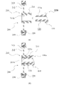
- FIG. 3 is a cross-sectional view showing how the crankshaft and torsional damper according to the first embodiment of the present invention are fixed.
- FIG. 4 is a cross-sectional view showing how a crankshaft and a torsional damper are fixed according to a second embodiment of the present invention.
- FIG. 5 is a sectional view of a conventional crankshaft and torsional damper.
- FIG. 6 is a part of a sectional view showing how a conventional crankshaft and a torsional damper are fixed.
- FIG. 1 is a front view showing the vicinity of the tip of a crankshaft according to Embodiment 1 of the present invention.
- FIG. 2 is a front view of a torsional damper according to Example 1 of the present invention.
- FIG. 3 is a cross-sectional view showing how the crankshaft and torsional damper according to the first embodiment of the present invention are fixed.
- the crankshaft in FIG. 3 is a cross-sectional view along AA in FIG. 1, and the torsional damper is a cross-sectional view along BB in FIG.
- a tip portion 120 having an outer diameter smaller than that of the crankshaft body 110 is provided on the tip side of the crankshaft body 110 .
- a fitting groove 121 extending parallel to the rotation center axis of the crankshaft 100 is provided on the outer peripheral surface of the tip portion 120 .
- the torsional damper 200 includes a hub 210 fixed to the crankshaft 100 , a vibration ring 230 , and a rubber-like elastic body 220 provided between the hub 210 and the vibration ring 230 .
- the hub 210 also includes a first cylindrical portion 211 , an outward flange portion 212 , and a second cylindrical portion 213 provided radially outside the outward flange portion 212 and concentrically with the first cylindrical portion 211 .
- a rubber-like elastic body 220 is press-fitted between the outer peripheral surface of the second cylindrical portion 213 and the inner peripheral surface of the vibration ring 230 .
- the inner peripheral surface of the first cylindrical portion 211 of the hub 210 serves as an insertion hole through which the tip portion 120 of the crankshaft 100 is inserted.
- a fitting protrusion 211a that fits into the fitting groove 121 is provided on the inner peripheral surface of the insertion hole.
- the fitting projection 211a extends parallel to the rotation center axis (the rotation center axis of the crankshaft 100 and the torsional damper 200) over the entire region of the insertion hole in the rotation center axis direction. is provided.
- crankshaft 100 and torsional damper 200 configured as described above, they can be fixed as follows. That is, the tip portion 120 of the crankshaft 100 and the torsional damper 200 are arranged so that their rotation center axes are aligned, and the fitting groove 121 and the fitting protrusion 211a are aligned in the circumferential direction (rotational direction). While maintaining (see FIG. 3A), the tip portion 120 is inserted (press-fitted) into the inner peripheral surface (insertion hole) of the first cylindrical portion 211 .
- the fitting groove 121 and the fitting protrusion 211a are fitted, and the crankshaft 100 and the torsional damper 200 are fixed (see FIG. 3(b)).
- the outer peripheral surface of the tip portion 120 and the inner peripheral surface of the first cylindrical portion 211 position the crankshaft 100 and the torsional damper 200 in the radial direction. Positioning in the circumferential direction (rotational direction) is performed by the joining portion.
- Embodiment 2 of the present invention is shown in FIG.
- the case where the fitting projection is provided over the entire area of the insertion hole in the torsional damper with respect to the rotation center axis direction has been described.
- this embodiment shows a case where the fitting projection is provided in a part of the insertion hole of the torsional damper with respect to the rotation center axis direction. Since other configurations and functions are the same as those of the first embodiment, the same components are denoted by the same reference numerals, and description thereof will be omitted as appropriate.
- FIG. 4 is a cross-sectional view showing how the crankshaft and torsional damper according to the second embodiment of the present invention are fixed.
- the crankshaft in FIG. 4 corresponds to the AA sectional view in FIG. 1, and the torsional damper corresponds to the BB sectional view in FIG.
- a tip portion 120 having a smaller outer diameter than the crankshaft body 110 is provided on the tip side of the crankshaft body 110 .
- a fitting groove 121 a extending parallel to the rotation center axis of the crankshaft 100 is provided on the outer peripheral surface of the tip portion 120 .
- the torsional damper 200 also includes a hub 210, a vibration ring 230, and a rubber-like elastic body 220, as in the first embodiment.
- the hub 210 includes a first cylindrical portion 211, an outward flange portion 212, and a second cylindrical portion 213, as in the first embodiment.
- the inner peripheral surface of the first cylindrical portion 211 of the hub 210 serves as an insertion hole through which the tip portion 120 of the crankshaft 100 is inserted.
- a fitting protrusion 211b that fits into the fitting groove 121a by press fitting is provided on the inner peripheral surface of the insertion hole.
- the fitting protrusion 211b is arranged in a part of the insertion hole in parallel with the rotation center axis (the rotation center axis of the crankshaft 100 and the torsional damper 200). is provided. Specifically, in the insertion hole, a fitting protrusion 211b is provided so as to extend from the end face on the side opposite to the side where the crankshaft 100 is inserted to a position midway toward the end face on the side where the crankshaft 100 is inserted.
- FIG. 4(a) shows the state during fixing work
- FIG. 4(b) shows the state after fixing.
- the same effect as in the first embodiment can be obtained in the present embodiment as well.
- the dimensional tolerance of the inner diameter of the insertion hole (the inner peripheral surface of the first cylindrical portion) of the hub 210 can be set to less than 0.03 mm, it is desirable to employ the configuration of this embodiment.
- the dimensional tolerance is 0.03 mm or more, it is desirable to adopt the configuration of the first embodiment.
- the fitting grooves 121 and 121a are provided at one circumferential location on the outer peripheral surface of the tip portion 120 of the crankshaft 100, and the fitting projections 211a and 211b are formed in the insertion holes of the torsional damper 200. The case where it is provided at one place in the circumferential direction is shown.
- the numbers of these fitting grooves and fitting protrusions are not particularly limited, and may be provided at two or more locations.
- Reference Signs List 100 100a crankshaft 110 crankshaft main body 120 tip portion 121, 121a fitting groove 200 torsional damper 210 hub 211 first cylindrical portion 211a, 211b fitting protrusion 212 outward flange portion 213 second cylindrical portion 220 rubber-like elastic body 230 vibration ring
Landscapes
- Engineering & Computer Science (AREA)
- General Engineering & Computer Science (AREA)
- Mechanical Engineering (AREA)
- Physics & Mathematics (AREA)
- Acoustics & Sound (AREA)
- Aviation & Aerospace Engineering (AREA)
- Shafts, Cranks, Connecting Bars, And Related Bearings (AREA)
Priority Applications (4)
| Application Number | Priority Date | Filing Date | Title |
|---|---|---|---|
| CN202280007697.8A CN116507816A (zh) | 2021-02-22 | 2022-02-21 | 曲轴与扭转减震器的固定结构 |
| JP2023500953A JPWO2022177001A1 (https=) | 2021-02-22 | 2022-02-21 | |
| US18/039,418 US20230417303A1 (en) | 2021-02-22 | 2022-02-21 | Fixing structure between crankshaft and torsional damper |
| EP22756318.6A EP4296531A4 (en) | 2021-02-22 | 2022-02-21 | Fixing structure between crankshaft and torsional damper |
Applications Claiming Priority (2)
| Application Number | Priority Date | Filing Date | Title |
|---|---|---|---|
| JP2021026412 | 2021-02-22 | ||
| JP2021-026412 | 2021-02-22 |
Publications (1)
| Publication Number | Publication Date |
|---|---|
| WO2022177001A1 true WO2022177001A1 (ja) | 2022-08-25 |
Family
ID=82930650
Family Applications (1)
| Application Number | Title | Priority Date | Filing Date |
|---|---|---|---|
| PCT/JP2022/006874 Ceased WO2022177001A1 (ja) | 2021-02-22 | 2022-02-21 | クランクシャフトとトーショナルダンパーとの固定構造 |
Country Status (5)
| Country | Link |
|---|---|
| US (1) | US20230417303A1 (https=) |
| EP (1) | EP4296531A4 (https=) |
| JP (1) | JPWO2022177001A1 (https=) |
| CN (1) | CN116507816A (https=) |
| WO (1) | WO2022177001A1 (https=) |
Citations (3)
| Publication number | Priority date | Publication date | Assignee | Title |
|---|---|---|---|---|
| JPH0177137U (https=) * | 1987-11-11 | 1989-05-24 | ||
| JP2002295588A (ja) * | 2001-03-30 | 2002-10-09 | Nok Vibracoustic Kk | トーショナルダンパ |
| JP2009236300A (ja) * | 2008-03-28 | 2009-10-15 | Toyota Motor Corp | トルク伝達部品の取付け構造 |
Family Cites Families (9)
| Publication number | Priority date | Publication date | Assignee | Title |
|---|---|---|---|---|
| US5231893A (en) * | 1991-12-10 | 1993-08-03 | Simpson Industries, Inc. | Dual mode damper |
| JP2007278417A (ja) * | 2006-04-07 | 2007-10-25 | Fukoku Co Ltd | ダンパおよびアイソレーションダンパプーリ |
| JP2011178228A (ja) * | 2010-02-26 | 2011-09-15 | Yamaha Motor Co Ltd | 船舶推進機用プロペラおよびこれを備える船舶推進機 |
| JP2012177469A (ja) * | 2011-01-31 | 2012-09-13 | Jtekt Corp | トーショナルダンパ |
| JP2015108395A (ja) * | 2013-12-04 | 2015-06-11 | 株式会社ジェイテクト | ダンパプーリ |
| JP6168487B1 (ja) * | 2015-12-04 | 2017-07-26 | Nok株式会社 | 環状のポケットと密封装置とを用いた密封構造 |
| JP2019090361A (ja) * | 2017-11-14 | 2019-06-13 | 株式会社豊田自動織機 | クランクプーリの取付構造 |
| JP6811702B2 (ja) * | 2017-12-19 | 2021-01-13 | Nok株式会社 | トーショナルダンパ |
| JP2019120312A (ja) * | 2017-12-28 | 2019-07-22 | 株式会社フコク | アイソレータ付プーリ |
-
2022
- 2022-02-21 CN CN202280007697.8A patent/CN116507816A/zh active Pending
- 2022-02-21 JP JP2023500953A patent/JPWO2022177001A1/ja active Pending
- 2022-02-21 WO PCT/JP2022/006874 patent/WO2022177001A1/ja not_active Ceased
- 2022-02-21 US US18/039,418 patent/US20230417303A1/en not_active Abandoned
- 2022-02-21 EP EP22756318.6A patent/EP4296531A4/en active Pending
Patent Citations (3)
| Publication number | Priority date | Publication date | Assignee | Title |
|---|---|---|---|---|
| JPH0177137U (https=) * | 1987-11-11 | 1989-05-24 | ||
| JP2002295588A (ja) * | 2001-03-30 | 2002-10-09 | Nok Vibracoustic Kk | トーショナルダンパ |
| JP2009236300A (ja) * | 2008-03-28 | 2009-10-15 | Toyota Motor Corp | トルク伝達部品の取付け構造 |
Non-Patent Citations (1)
| Title |
|---|
| See also references of EP4296531A4 |
Also Published As
| Publication number | Publication date |
|---|---|
| EP4296531A1 (en) | 2023-12-27 |
| JPWO2022177001A1 (https=) | 2022-08-25 |
| US20230417303A1 (en) | 2023-12-28 |
| EP4296531A4 (en) | 2025-01-15 |
| CN116507816A (zh) | 2023-07-28 |
Similar Documents
| Publication | Publication Date | Title |
|---|---|---|
| US9664107B2 (en) | Driving device for hybrid working machine | |
| JP3672017B2 (ja) | 内燃機関の出力シャフトに接続された支持体に歯付きスタータ・リングを結合するための系 | |
| JPH09210130A (ja) | 軸状部材に対する筒状部材の固定構造 | |
| JPH10184717A (ja) | トリポード型等速自在継手及びその製造方法 | |
| KR20200139575A (ko) | 휠베어링 조립체 | |
| WO2022177001A1 (ja) | クランクシャフトとトーショナルダンパーとの固定構造 | |
| JP2010133266A (ja) | 過給機の軸受装置 | |
| JP2008281099A (ja) | センターベアリングサポート | |
| US20100279778A1 (en) | Torsional vibration damper | |
| CN110259840A (zh) | 内球笼装配结构 | |
| JP7013315B2 (ja) | 曲げダンパ付きトーショナルダンパ | |
| JP3507558B2 (ja) | 回転軸の制振装置および回転軸 | |
| JP2000329180A (ja) | 防振ブッシュ | |
| JP3552770B2 (ja) | トーショナルダンパ | |
| JP7494335B2 (ja) | 動吸振器 | |
| JP2002295588A (ja) | トーショナルダンパ | |
| JP2020139606A (ja) | トーショナルダンパー | |
| JP2018062962A (ja) | 摩擦プーリ | |
| JPH06300117A (ja) | デュアルタイプダンパープーリ | |
| TW202548151A (zh) | 禮帽型諧波齒輪裝置 | |
| JP2021124166A (ja) | トーショナルダンパー | |
| JPH06341449A (ja) | 自在継手 | |
| JPH0293143A (ja) | エンジンのフライホイール装置 | |
| JP2007100851A (ja) | 回転変動吸収ダンパー | |
| JP2020008145A (ja) | トーショナルダンパ |
Legal Events
| Date | Code | Title | Description |
|---|---|---|---|
| 121 | Ep: the epo has been informed by wipo that ep was designated in this application |
Ref document number: 22756318 Country of ref document: EP Kind code of ref document: A1 |
|
| WWE | Wipo information: entry into national phase |
Ref document number: 202280007697.8 Country of ref document: CN |
|
| WWE | Wipo information: entry into national phase |
Ref document number: 18039418 Country of ref document: US |
|
| ENP | Entry into the national phase |
Ref document number: 2023500953 Country of ref document: JP Kind code of ref document: A |
|
| WWE | Wipo information: entry into national phase |
Ref document number: 2022756318 Country of ref document: EP |
|
| NENP | Non-entry into the national phase |
Ref country code: DE |
|
| ENP | Entry into the national phase |
Ref document number: 2022756318 Country of ref document: EP Effective date: 20230922 |