WO2022163526A1 - 照明システム、制御方法及びプログラム - Google Patents
照明システム、制御方法及びプログラム Download PDFInfo
- Publication number
- WO2022163526A1 WO2022163526A1 PCT/JP2022/002194 JP2022002194W WO2022163526A1 WO 2022163526 A1 WO2022163526 A1 WO 2022163526A1 JP 2022002194 W JP2022002194 W JP 2022002194W WO 2022163526 A1 WO2022163526 A1 WO 2022163526A1
- Authority
- WO
- WIPO (PCT)
- Prior art keywords
- light
- blue
- lighting
- emits
- led
- Prior art date
- Legal status (The legal status is an assumption and is not a legal conclusion. Google has not performed a legal analysis and makes no representation as to the accuracy of the status listed.)
- Ceased
Links
Images


Classifications
-
- G—PHYSICS
- G08—SIGNALLING
- G08B—SIGNALLING SYSTEMS, e.g. PERSONAL CALLING SYSTEMS; ORDER TELEGRAPHS; ALARM SYSTEMS
- G08B5/00—Visible signalling systems, e.g. visible personal calling systems or remote indication of seats occupied
- G08B5/22—Visible signalling systems, e.g. visible personal calling systems or remote indication of seats occupied using electric transmission; using electromagnetic transmission
- G08B5/36—Visible signalling systems, e.g. visible personal calling systems or remote indication of seats occupied using electric transmission; using electromagnetic transmission using visible light sources
-
- H—ELECTRICITY
- H05—ELECTRIC TECHNIQUES NOT OTHERWISE PROVIDED FOR
- H05B—ELECTRIC HEATING; ELECTRIC LIGHT SOURCES NOT OTHERWISE PROVIDED FOR; CIRCUIT ARRANGEMENTS FOR ELECTRIC LIGHT SOURCES, IN GENERAL
- H05B47/00—Circuit arrangements for operating light sources in general, i.e. where the type of light source is not relevant
- H05B47/10—Controlling the light source
- H05B47/105—Controlling the light source in response to determined parameters
- H05B47/115—Controlling the light source in response to determined parameters by determining the presence or movement of objects or living beings
- H05B47/13—Controlling the light source in response to determined parameters by determining the presence or movement of objects or living beings by using passive infrared detectors
-
- G—PHYSICS
- G01—MEASURING; TESTING
- G01C—MEASURING DISTANCES, LEVELS OR BEARINGS; SURVEYING; NAVIGATION; GYROSCOPIC INSTRUMENTS; PHOTOGRAMMETRY OR VIDEOGRAMMETRY
- G01C21/00—Navigation; Navigational instruments not provided for in groups G01C1/00 - G01C19/00
- G01C21/20—Instruments for performing navigational calculations
- G01C21/206—Instruments for performing navigational calculations specially adapted for indoor navigation
-
- G—PHYSICS
- G05—CONTROLLING; REGULATING
- G05D—SYSTEMS FOR CONTROLLING OR REGULATING NON-ELECTRIC VARIABLES
- G05D1/00—Control of position, course, altitude or attitude of land, water, air or space vehicles, e.g. using automatic pilots
- G05D1/02—Control of position or course in two dimensions
- G05D1/021—Control of position or course in two dimensions specially adapted to land vehicles
- G05D1/0212—Control of position or course in two dimensions specially adapted to land vehicles with means for defining a desired trajectory
- G05D1/0214—Control of position or course in two dimensions specially adapted to land vehicles with means for defining a desired trajectory in accordance with safety or protection criteria, e.g. avoiding hazardous areas
-
- H—ELECTRICITY
- H05—ELECTRIC TECHNIQUES NOT OTHERWISE PROVIDED FOR
- H05B—ELECTRIC HEATING; ELECTRIC LIGHT SOURCES NOT OTHERWISE PROVIDED FOR; CIRCUIT ARRANGEMENTS FOR ELECTRIC LIGHT SOURCES, IN GENERAL
- H05B47/00—Circuit arrangements for operating light sources in general, i.e. where the type of light source is not relevant
- H05B47/10—Controlling the light source
- H05B47/105—Controlling the light source in response to determined parameters
- H05B47/115—Controlling the light source in response to determined parameters by determining the presence or movement of objects or living beings
- H05B47/125—Controlling the light source in response to determined parameters by determining the presence or movement of objects or living beings by using cameras
-
- H—ELECTRICITY
- H05—ELECTRIC TECHNIQUES NOT OTHERWISE PROVIDED FOR
- H05B—ELECTRIC HEATING; ELECTRIC LIGHT SOURCES NOT OTHERWISE PROVIDED FOR; CIRCUIT ARRANGEMENTS FOR ELECTRIC LIGHT SOURCES, IN GENERAL
- H05B47/00—Circuit arrangements for operating light sources in general, i.e. where the type of light source is not relevant
- H05B47/10—Controlling the light source
- H05B47/155—Coordinated control of two or more light sources
-
- G—PHYSICS
- G08—SIGNALLING
- G08G—TRAFFIC CONTROL SYSTEMS
- G08G1/00—Traffic control systems for road vehicles
- G08G1/123—Traffic control systems for road vehicles indicating the position of vehicles, e.g. scheduled vehicles; Managing passenger vehicles circulating according to a fixed timetable, e.g. buses, trains, trams
-
- H—ELECTRICITY
- H05—ELECTRIC TECHNIQUES NOT OTHERWISE PROVIDED FOR
- H05B—ELECTRIC HEATING; ELECTRIC LIGHT SOURCES NOT OTHERWISE PROVIDED FOR; CIRCUIT ARRANGEMENTS FOR ELECTRIC LIGHT SOURCES, IN GENERAL
- H05B45/00—Circuit arrangements for operating light-emitting diodes [LED]
- H05B45/20—Controlling the colour of the light
Definitions
- the present disclosure generally relates to a lighting system, a control method and a program, and more particularly relates to a lighting system including a plurality of lighting devices and a control method and program for controlling the plurality of lighting devices.
- Patent Document 1 a lighting control system having a plurality of lighting fixtures that illuminate a plurality of areas and a lighting control unit that controls the control values of one or more lighting fixtures that illuminate a non-human area or a human presence area is known.
- An object of the present disclosure is to provide a lighting system, a control method, and a program that allow the lighting device to be used for multiple purposes.
- a lighting system includes a plurality of lighting devices and a control device.
- the plurality of lighting devices are arranged in a facility.
- the control device controls the plurality of lighting devices.
- the control device changes the illumination light of at least one of the plurality of lighting devices to a color different from white so as to present a sign based on the target event. Control to light.
- a control method is a control method for controlling a plurality of lighting devices arranged in a facility, wherein when information regarding a target event is obtained, a sign based on the target event is presented. and controlling illumination light from at least one illumination device among the plurality of illumination devices to color illumination light having a color different from white.
- a program of one aspect according to the present disclosure is a program for causing a computer system to execute the control method of the above aspect.
- FIG. 1 is a block diagram of a lighting system according to Embodiment 1.
- FIG. FIG. 2 is a schematic explanatory diagram showing a mode of use of the illumination system of the same.
- FIG. 3 is a partially broken plan view showing a light source of an illumination device in the same illumination system.
- FIG. 4 is a flow chart of the operation of the illumination system of the same.
- FIG. 5 is an explanatory diagram of a first example of the operation of the illumination system;
- FIG. 6 is an explanatory diagram of a second example of the operation of the illumination system;
- FIG. 7 is a partially broken plan view showing a light source in Modification 1 of the lighting device in the lighting system.
- FIG. 8 is a partially broken plan view showing a light source in Modification 2 of the lighting device in the lighting system.
- FIG. 9 is a schematic explanatory diagram showing a usage pattern of the lighting system according to the second embodiment.
- 10 is a block diagram of a lighting system according to Embodiment 3.
- FIG. 11 is an explanatory diagram of a first example of the operation of the illumination system;
- FIG. 12 is an explanatory diagram of a second example of the operation of the illumination system;
- FIG. 13 is an explanatory diagram of a third example of the operation of the illumination system;
- 14 is a block diagram of a lighting system according to Embodiment 4.
- FIG. FIG. 15 is an explanatory diagram of a first example of the operation of the illumination system;
- FIG. 16 is an explanatory diagram of a second example of the operation of the illumination system;
- FIG. 15 is an explanatory diagram of a first example of the operation of the illumination system;
- FIG. 16 is an explanatory diagram of a second example of the operation of the illumination system;
- FIG. 17 is an explanatory diagram of a third example of the operation of the illumination system; 18 is a partially broken plan view showing a light source in Modification 3 of the lighting device in the lighting system according to Embodiment 1.
- FIG. FIG. 19 is a partially broken plan view showing a light source in Modification 4 of the lighting device in the lighting system.
- FIG. 20 is a partially broken plan view showing a light source in Modified Example 5 of the lighting device in the lighting system.
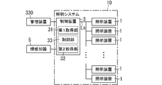
- a lighting system 10 according to Embodiment 1 includes a plurality of lighting devices 1 and a control device 3, as shown in FIG.
- the control device 3 controls the plurality of lighting devices 1 .
- a plurality of lighting devices 1 are arranged in a facility 200 as shown in FIG.
- the facility 200 is assumed to be a building, particularly an office building.
- the space facing the plurality of lighting devices 1 in the facility 200 is referred to as a target space 201 .
- the target space 201 is a space used by the person P10 within the facility 200 . Examples of target space 201 include conference rooms, working spaces, co-working spaces, and recreation rooms.
- the facilities 200 are not limited to office buildings, but may be offices, factories, hospitals, hotels, stadiums, amusement facilities, airports, detached houses, collective housing, and the like.
- the control device 3 changes the illumination light of at least one of the plurality of lighting devices 1 to a color different from white so as to present a sign based on the target event. Control to light.
- the light exit surfaces of four illumination devices 1, among a plurality of (eg, 12) illumination devices 1, which are illuminated with colored illumination light of a color (eg, red) different from white are hatched with dots. Dot hatching is not applied to the light exit surface of the illumination device 1 which illuminates the illumination light of .
- FIG. 1 Details The lighting system 10 according to the first embodiment will be described in further detail below with reference to FIGS. 1 to 6.
- FIG. 1 is a diagrammatic representation of the lighting system 10 according to the first embodiment.
- the lighting system 10 includes a plurality of lighting devices 1 and a control device 3 as described above.
- a plurality of lighting devices 1 are arranged on a ceiling 202 facing a target space 201 in a facility 200 .
- a target space 201 is a space under the ceiling 202 .
- a desk 220, a chair 230, and the like are arranged as fixtures usable by the person P10.
- the plurality of lighting devices 1 has a square shape when viewed from the target space 201, but is not limited to this, and may have, for example, a rectangular shape or a circular shape.
- a plurality of lighting devices 1 are arranged in a two-dimensional array when viewed from the target space 201 .
- the plurality of lighting devices 1 may be ceiling-embedded lighting fixtures, ceiling-mounted lighting fixtures, or panel-shaped lighting fixtures supported by grid-shaped support members included in the system ceiling. , Ceiling-hanging luminaires may also be used.
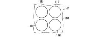
- Each of the plurality of lighting devices 1 includes a light source 11 (see FIG. 3).
- the light source 11 has a blue LED (Light Emitting Diode) 11B, a green LED 11G, a red LED 11R, and a white LED 11W.
- the white LED 11W emits white light.
- the correlated color temperature of the white light emitted from the white LED 11W is, for example, 2700K or more and 6000K or less.
- the white LED 11W includes, for example, a blue LED chip and a wavelength conversion section including a wavelength conversion element that converts the wavelength of part of the blue light emitted from the blue LED chip and emits light with a wavelength different from that of the blue light. have.
- the wavelength converting elements are phosphor particles.
- the wavelength conversion section includes, for example, a translucent material section and phosphor particles.
- the wavelength converting portion is formed of a mixture of the translucent material portion and the phosphor particles.
- the material of the translucent material portion is preferably a material having high visible light transmittance.
- the translucent material is, for example, silicone-based resin.
- the phosphor particles for example, yellow phosphor particles that emit yellow light can be used.
- the light (fluorescence) emitted from the yellow phosphor particles preferably has an emission spectrum with a main emission peak wavelength in the wavelength range of 530 nm to 580 nm, for example.
- the yellow phosphor particles are, for example, Y 3 Al 5 O 12 activated with Ce, but are not limited thereto.
- the wavelength conversion part is not limited to the case where only yellow phosphor particles are included as wavelength conversion elements.
- yellow phosphor particles, yellow-green phosphor particles, green phosphor particles, and red phosphor particles may be included.
- the wavelength conversion section may contain a plurality of types of phosphor particles. Yellow-green phosphor particles emit yellow-green light. Green phosphor particles emit green light. Red phosphor particles emit red light.
- the light source 11 has a mounting board 110 as shown in FIG.
- the mounting board 110 is, for example, a printed wiring board.
- the blue LED 11B, the green LED 11G, the red LED 11R and the white LED 11W are mounted on the mounting board 110.
- the light source 11 has a plurality of sets of a blue LED 11B, a green LED 11G, a red LED 11R, and a white LED 11W on one mounting board 110 .
- Each of the plurality of lighting devices 1 includes a first drive circuit that drives the plurality of blue LEDs 11B, a second drive circuit that drives the plurality of green LEDs 11G, a third drive circuit that drives the plurality of red LEDs 11R, and a plurality of A fourth drive circuit for driving the white LED 11W and a control circuit for controlling the first to fourth drive circuits are provided.
- the control circuit controls the first to fourth drive circuits to select any one of white light, blue light, green light, and red light as illumination light, or It is possible to output light of a color obtained by mixing two or more of these colors.
- each of the plurality of lighting devices 1 has a chromaticity point of blue light emitted from the blue LED 11B and a chromaticity point of green light emitted from the green LED 11G in the xy chromaticity diagram of the XYZ color system. and the chromaticity point of the red light emitted from the red LED 11R, and the light of a color corresponding to an arbitrary chromaticity point within the range of the triangle having the apexes thereof can be output as colored illumination light or white light. It is possible.
- the white light is preferably light of chromaticity corresponding to a chromaticity point on the black body locus in the xy chromaticity diagram of the XYZ color system.
- control device 3 can be connected via a communication network to the management device 330 (see FIG. 1) that stores facility information on the facility 200 (see FIG. 2).
- the management device 330 is, for example, a server.
- a communication network may include the Internet.
- the communication network may consist of not only a network conforming to a single communication protocol, but also a plurality of networks conforming to different communication protocols. Communication protocols may be selected from a variety of well-known wired and wireless communication standards.
- a communication network may include, for example, data communication equipment such as repeater hubs, switching hubs, bridges, gateways, routers, and the like.
- the facility information is, for example, part or all of three-dimensional data representing the structure of the facility 200.
- the three-dimensional data is data representing the facility 200 in a virtual space constructed using a computer. This type of three-dimensional data is, for example, BIM (Building Information Modeling) data. Below, three-dimensional data is called "BIM data.”
- BIM data includes not only data representing the shape and dimensions of the facility 200, but also various types of data related to the facility 200, such as data related to the members that make up the facility 200 and data related to equipment installed in the facility 200. are integrated.
- the BIM data also includes information on the latitude and longitude of the reference position of the facility 200 and information on the orientation of the facility 200 .
- the BIM data represents not only the data for building the facility 200 but also various data relating to the facility 200 .
- BIM data is information expressed using, for example, a three-dimensional CAD (Computer Aided Design) system, and is created using data representing the shape and dimensions of the facility 200 .
- CAD Computer Aided Design
- BIM data By using BIM data, for example, it is possible to display a graphic representing the whole or part of the facility 200 on the display.
- BIM data is hierarchized according to the facility 200 .
- BIM data includes, for example, information representing the entire facility 200 in a front view or a perspective view, information representing each of a plurality of floors of the facility 200 in a plan view or a perspective view, or information representing one floor in a plan view or a perspective view. contains.
- BIM data includes data representing a perspective view of an entire building that is the facility 200, data representing a plan view of one floor in the building, or data representing a perspective view of a room viewed from the inside.
- Both facility information (BIM data) and location information can be displayed using software capable of executing a program written in a programming language such as Java (registered trademark).
- a web browser compatible with WebGL can display three-dimensional data of the facility 200 on the display unit.
- the control device 3 has a first acquisition unit 31 that acquires BIM data from the management device 330, as shown in FIG.
- the control device 3 also has a second acquisition unit 32 that acquires fire outbreak information regarding the facility 200 (see FIG. 2).
- the second acquisition unit 32 acquires a fire occurrence signal (an alarm signal) from, for example, the smoke sensor 5 (see FIG. 1) installed in the facility 200 or an automatic fire alarm system.
- An automatic fire alarm system is a disaster prevention system capable of notifying people in a building of a fire prevention target of the outbreak of a fire, for example, when the outbreak of a fire is detected.
- the fire prevention object is the facility 200 .
- a smoke detector 5 may be included, for example, as a component of an automatic fire alarm system.
- the control device 3 also has a control unit 33 that controls the plurality of lighting devices 1 .
- the control device 3 and the plurality of lighting devices 1 are connected via, for example, signal lines Ls, and control signals can be transmitted from the control device 3 to the plurality of lighting devices 1 .
- Individual identification information (unique address) is set for each of the plurality of lighting devices 1 .
- a plurality of lighting devices 1 each have a storage unit that stores a unique address.
- the control unit 33 has, as operation modes, for example, a first mode (collective control mode) in which two or more lighting devices 1 out of the plurality of lighting devices 1 are collectively controlled with the same control content; Alternatively, it has a second mode (pattern control mode) in which two or more lighting devices 1 are individually controlled in advance, and a third mode (individual control mode) in which a plurality of lighting devices 1 are individually controlled. is doing.
- the control unit 33 includes a memory that stores unique addresses for each of the lighting devices 1 .
- the control unit 33 stores a collective control address used in the first mode and a group control address used in the second mode in the memory described above. In this case, the storage units of the plurality of lighting devices 1 store group control addresses and batch control addresses in addition to unique addresses.
- the control device 3 Based on the BIM data acquired by the first acquisition unit 31, the control device 3 identifies the positional information of the plurality of lighting devices 1 in the facility 200 (the positional coordinates of the lighting devices 1 in the facility 200).
- the positional information of the plurality of lighting devices 1 and the unique addresses of the plurality of lighting devices 1 are associated one-to-one and stored in the above memory.
- the control signal from the control unit 33 to each lighting device 1 includes address data corresponding to the unique address of the lighting device 1 to be controlled, the collective control address, or the group control address, and the control content of the lighting device 1 to be controlled ( and control data indicating the color of illumination light, lighting, lighting, blinking, illuminance, etc.).
- the color of the illumination light is white or a color different from white (for example, red, green, blue, etc.).
- the control content may include control data including control content indicating the chromaticity of the illumination light instead of including control data including the control content indicating the color of the illumination light.
- the control unit 33 When the second acquiring unit 32 acquires information (here, fire occurrence information) about the target event (here, fire), the control unit 33 presents a plurality of (fire) signs based on the target event (fire).
- the illumination light of at least one (four in the example of FIG. 5) of the illumination devices 1 of 12) is controlled to color illumination light of a color different from white.
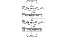
- the control unit 33 when the control unit 33 acquires information about the target event (step S11: Yes), the illumination light of at least one lighting device 1 is turned on to present a sign based on the target event. is controlled to color illumination light of a color different from white (for example, red) (step S12).
- step S14 the control of the color illumination light is finished (step S14).
- “Ending the control of the color illumination light” means, for example, controlling the illumination light of the illumination device 1 to be white or turning off the illumination device 1 .
- the controller 33 operates, for example, in the above-described second mode. If the target event is a fire, there is a possibility that visibility is poor due to smoke.
- the color of the light is preferably a color with a long wavelength, for example, red, from the viewpoint of improving visibility.
- the control device 3 also stores position information of the smoke sensor 5 based on the BIM data.
- the target event is an event (here, fire) that needs to guide the person P10 in the facility 200.
- the control device 3 guides the person P10 staying in the target space 201 in the facility 200 in a direction D10 as a sign for the person P10 in the facility 200.
- At least one lighting device 1 is controlled to present a sign indicating a direction (for example, a direction from the target space 201 to an emergency exit or exit).
- the control device 3 may indicate a sign indicating a direction D10 to guide the person P10 by gradation of color illumination light.
- the color intensity of the color illumination light of the illumination device 1 that is the starting point is the lowest, and the gradation of the color illumination light is the lighting device that is the end point.
- the gradation is such that the color gradation of the color illumination light of 1 is the highest, and the color gradation of the color illumination light gradually increases as the distance from the illumination device 1 at the starting point approaches the illumination device 1 at the end point.
- the degree of gradation of color illumination light on the light exit surfaces of the four illumination devices 1 is distinguished by the type of dot hatching.
- FIG. 6 may be sequentially changed along the guiding direction.
- FIG. 6 among the plurality of lighting devices 1, only the light exit surface of the lighting device 1 that outputs color illumination light is hatched with dots.
- the control device 3 includes a computer system.
- a computer system is mainly composed of a processor and a memory as hardware.
- the function of the control device 3 is realized by the processor executing a program recorded in the memory of the computer system.
- the program may be recorded in advance in the memory of the computer system, may be provided through an electric communication line, or may be recorded in a non-temporary recording medium such as a computer system-readable memory card, optical disk, or hard disk drive. may be provided.
- a processor in a computer system consists of one or more electronic circuits, including semiconductor integrated circuits (ICs) or large scale integrated circuits (LSIs).
- Integrated circuits such as ICs or LSIs are called differently depending on the degree of integration, and include integrated circuits called system LSI, VLSI (Very Large Scale Integration), or ULSI (Ultra Large Scale Integration).
- FPGAs Field-Programmable Gate Arrays
- a plurality of electronic circuits may be integrated into one chip, or may be distributed over a plurality of chips.
- a plurality of chips may be integrated in one device, or may be distributed in a plurality of devices.
- a computer system includes a microcontroller having one or more processors and one or more memories. Accordingly, the microcontroller also consists of one or more electronic circuits including semiconductor integrated circuits or large scale integrated circuits.
- the control method according to the first embodiment is a control method for controlling a plurality of lighting devices 1 arranged within the facility 200 .
- the illumination light of at least one of the plurality of lighting devices 1 is changed from white to present a sign based on the target event. Control to color color illumination light.
- the program according to the first embodiment is a program for causing the computer system (control device 3) to execute the control method described above.
- the lighting system 10 includes a plurality of lighting devices 1 and a control device 3 .
- a plurality of lighting devices 1 are arranged in a facility 200 .
- the control device 3 controls the plurality of lighting devices 1 .
- the control device 3 acquires information on the target event (fire occurrence information)
- the control device 3 sets the illumination light of at least one of the plurality of lighting devices 1 to be white so as to present a sign based on the target event. Control to color illumination light of different colors. Accordingly, in the lighting system 10 according to the first embodiment, the lighting device 1 can be used for multiple purposes.
- the lighting system 10 can use the plurality of lighting devices 1 as main lighting for illuminating the target space 201 of the facility 200 when the control device 3 does not acquire information about the target event, and the control device 3 acquires information about the target event, the lighting device 1 can be used as signage lighting for presenting a sign based on the target event.
- the lighting system 10 can present a sign that guides the person P10 staying in the target space 201 to an evacuation route such as an emergency exit when a fire breaks out in the facility 200. becomes.
- the light source 11 included in each of the plurality of lighting devices 1 includes a first blue LED 111, a second blue LED 112, a first wavelength conversion section 121, a second wavelength conversion section 122, It has a visible light LED 13 (hereinafter also referred to as a first visible light LED 13) and a visible light LED 14 (hereinafter also referred to as a second visible light LED 14).
- the first blue LED 111 emits first blue light.
- the second blue LED 112 emits second blue light.
- the first wavelength converter 121 includes green phosphor particles that are excited by the first blue light to emit green light.
- the second wavelength converter 122 includes red phosphor particles that are excited by the second blue light to emit red light.
- the first visible light LED 13 emits visible light of a color different from the first blue light, the second blue light, and white (hereinafter also referred to as the first visible light).
- the second visible light LED 14 emits visible light of a color different from the first blue light, the second blue light, and white (hereinafter also referred to as the second visible light).
- the peak wavelength of the second blue light may be the same as or different from the peak wavelength of the first blue light.
- the first visible light is, for example, red light.
- the second visible light is, for example, green light.
- the first visible light and the second visible light are not limited to light of different colors, and may be light of the same color.
- the light source 11 is not limited to including both the first visible light LED 13 and the second visible light LED 14, and may include at least one of them.
- First blue LED 111 , second blue LED 112 , first wavelength conversion section 121 , second wavelength conversion section 122 , first visible light LED 13 , and second visible light LED 14 are provided on mounting board 110 .
- the light source 11 includes a first blue LED 111, a second blue LED 112, a first wavelength conversion section 121, a second wavelength conversion section 122, a first visible light LED 13, and a second blue LED 112 on one mounting substrate 110. It has a plurality of sets with 2 visible light LEDs 14 .
- Each of the plurality of lighting devices 1 includes a drive circuit that drives the plurality of first blue LEDs 111, a drive circuit that drives the plurality of second blue LEDs 112, a drive circuit that drives the plurality of first visible light LEDs, and a plurality of and a control circuit for controlling each drive circuit.
- Modified Example 1 it is possible to improve the color rendering properties of the illumination light of the lighting device 1 when the lighting device 1 is used for main lighting purposes.
- the light source 11 included in each of the plurality of lighting devices 1 includes a first violet LED 131, a second violet LED 132, a third violet LED 133, a first wavelength converter 141, and a second It has a wavelength converter 142 and a third wavelength converter 143 . Moreover, the light source 11 further has a visible light LED 15 .
- the first violet LED 131 emits first violet light.
- the second violet LED 132 emits second violet light.
- the third violet LED 133 emits third violet light.
- the first wavelength converter 141 includes blue phosphor particles that are excited by the first violet light to emit blue light.
- the second wavelength converter 142 includes green phosphor particles that are excited by the second violet light to emit green light.
- the third wavelength converter 143 includes red phosphor particles that are excited by the third violet light to emit red light.
- Visible light LED 15 emits visible light (eg, red light).
- the peak wavelengths of the first violet light, the second violet light, and the third violet light may be the same or different.
- the visible light emitted from the visible light LED 15 is not limited to red light, and may be green light, for example. Further, the light source 11 may be configured without the visible light LED 15 .
- the first violet LED 131, the second violet LED 132, the third violet LED 133, the first wavelength conversion section 141, the second wavelength conversion section 142, the third wavelength conversion section 143, and the visible light LED 15 are mounted on a mounting substrate. 110. Further, the light source 11 includes a first violet LED 131, a second violet LED 132, a third violet LED 133, a first wavelength conversion section 141, a second wavelength conversion section 142, and a third A plurality of sets of the wavelength conversion unit 143 and the visible light LED 15 are provided.
- Each of the plurality of lighting devices 1 includes a drive circuit that drives the plurality of first violet LEDs 131, a drive circuit that drives the plurality of second violet LEDs 132, a drive circuit that drives the plurality of third violet LEDs 133, and a plurality of A drive circuit for driving the visible light LED 15 and a control circuit for controlling each drive circuit are provided.
- the lighting system 10 a further includes a plurality of second lighting devices 2 arranged in the facility 200 separately from the plurality of first lighting devices 1 that are the plurality of lighting devices 1 .
- the illumination light from the plurality of second lighting devices 2 is white light.
- the illumination light from the plurality of second lighting devices 2 is white light with a correlated color temperature of 2700K or more and 6000K or less.
- the control device 3 controls the multiple lighting devices 1 and the multiple second lighting devices 2 .
- the control device 3 stores identification information and position information of the plurality of second lighting devices 2 .
- the second lighting device 2 is arranged adjacent to the first lighting device 1 in one direction.
- the light exit surface of the first lighting device 1 is rectangular.
- the light exit surface of the second lighting device 2 is rectangular.
- the area of the light exit surface of the first lighting device 1 is smaller than the area of the light exit surface of the second lighting device 2 .
- the lighting area of the first lighting device 1 is narrower than the lighting area of the second lighting device 2 .
- the illumination system 10a can use illumination light from the plurality of second illumination devices 2 as main illumination.
- the control device 3 controls the illumination light of at least one first lighting device 1 out of the plurality of first lighting devices 1 so as to present a sign based on the target event. is controlled to color illumination light of a color different from white.
- dots are shown on the light exit surfaces of four first lighting devices 1 that illuminate color illumination light (for example, red) different from white among the plurality (for example, nine) of first lighting devices 1 . Hatching is applied, and dot hatching is not applied to the light exit surface of the first lighting device 1 which is illuminated with white illumination light or is extinguished.
- the plurality of second lighting devices 2 may be capable of adjusting the correlated color temperature of the illumination light.
- the illumination system 10b according to the third embodiment will be described below with reference to FIGS. 10 and 11.
- FIG. The lighting system 10b according to the third embodiment differs from the lighting system 10 according to the first embodiment in that it includes a control device 3b instead of the control device 3 in the lighting system 10 according to the first embodiment.
- the same components as those of the lighting system 10 according to the first embodiment are denoted by the same reference numerals, and description thereof is omitted.
- control device 3b acquires information about the target event from the sensor system 340.
- the sensor system 340 includes an image sensor including a camera that captures an image of the target space 201 facing the multiple lighting devices 1 in the facility 200 .
- the imaging element in the camera is a CMOS (Complementary MOS) image sensor.
- the imaging element is not limited to a CMOS image sensor, and may be, for example, a CCD (Charge Coupled Device) image sensor, an infrared image sensor, or the like.
- the image sensor can detect the state of the person P10 or the like in the target space 201 based on the image captured by the camera and generated.
- the image sensor can detect the state of the person P10 by obtaining the feature amount of the target object (person P10 or the like) by performing image processing on the image.
- Sensor system 340 may include multiple image sensors for one object space 201 . In the sensor system 340, individual identification information (address) is set for each image sensor.
- the control device 3b includes an acquisition unit 31b that acquires information on a target event from the sensor system 340, and a plurality of lighting devices that present a sign based on the target event when the acquisition unit 31b acquires information on the target event. and a control unit 33b for controlling the illumination light of at least one illumination device 1 out of the 1 to color illumination light of a color different from white. Based on the position information of the lighting device 1, the lighting area of the lighting device 1, the position information of the image sensor, the imaging area of the camera of the image sensor, and the like, the control device 3b stores the information of one image sensor in the memory of the control unit 33b.
- the identification information may be stored in association with the identification information of one lighting device 1, or the identification information of one image sensor may be stored in association with the identification information of two or more lighting devices 1. .
- the target event is an event that requires attention in the traveling direction of the person P10 in the facility 200.
- the control device 3b controls at least one lighting device 1 so as to present, as a sign, a sign calling attention to the traveling direction of the person P10 when the information on the target event is acquired.
- the control device 3b acquires information about an event requiring attention in the traveling direction of the person P10 in the facility 200 as information about the target event, the color lighting of the lighting device 1 The light makes it possible to present a sign calling attention to the traveling direction of the person P10.
- the target events are the event that the floor surface 203 is wet and the event that the person P11 is lying down in the direction in which the person P10 in the facility 200 moves.
- the light exit surfaces of two illumination devices 1, among a plurality of (eg, 12) illumination devices 1, which are illuminated with color illumination light of a color (eg, red) different from white are hatched with dots. Dot hatching is not applied to the light exit surface of the illumination device 1 which is illuminated with the illumination light of , or is extinguished.
- the illumination system 10b presents a sign calling attention to the fact that the floor surface 203 is wet, which can help prevent the person P10 from falling. Further, in the lighting system 10b, it is possible to notify the presence of the fallen person P11 by presenting a sign calling attention to the event that the person P11 has fallen down.
- the target event is an event in which the chair 230 is positioned in front of the person P10 in the traveling direction of the person P10 in the facility 200.
- the light exit surface of one of the plurality of (for example, 12) lighting devices 1 that illuminates color illumination light of a color (for example, red) different from white is hatched with dots. Dot hatching is not applied to the light exit surface of the illumination device 1 which is illuminated with the illumination light of , or is extinguished.
- the lighting system 10b it is possible to prevent the person P10 from colliding with the chair 230 by drawing attention to the fact that the chair 230 is positioned in front of the person P10 in the traveling direction of the person P10.
- the target event is an event in which a person P10 (P11) approaches an intersection of passages in the facility 200 from the first direction D1.
- the control device 3b uses the signal as a sign to indicate the person P10 (P12) approaching the intersection from the first direction D1 in the second direction D2, which is different from the first direction D1.
- a lighting device 1 for lighting an intersection among a plurality of lighting devices 1 is controlled so as to present a sign indicating that there is an intersection.
- the light exit surfaces of two illumination devices 1 that illuminate color illumination light of a color (eg, red) different from white among a plurality of (eg, 10) illumination devices 1 are hatched with dots.
- the lighting system 10b may control the lighting device 1 to change the color of the colored illumination light based on the approach speed of the person P10 (P11) approaching the intersection. For example, when the approach speed is slower than the threshold, the color of the colored illumination light may be yellow, and when the approach speed is equal to or higher than the threshold, the color of the colored illumination light may be red.
- the target event may be an event in which the robot Ro1 is moving within the facility 200.
- the control device 3b controls at least one lighting device 1 to present a sign indicating the planned movement route of the robot Ro1 in the facility 200 as a sign when the information on the target event is acquired.
- the lighting system 10b can call the person P10 in the facility 200 to pay attention to the robot Ro1.
- the control device 3b controls at least one lighting device 1 so as to present a sign showing the planned movement route of the robot Ro1 in the facility 200 to the person P10 around the robot Ro1.
- the control device 3b controls at least one lighting device 1 to present, as a sign, to the robot Ro1 in the facility 200 a sign informing the next movement route of the robot Ro1 when the information on the target event is acquired. It may be configured as
- the target event may be an event in which the person P10 (P11) in the facility 200 is walking carelessly ahead.
- the sensor system 340 detects a person P10 who is walking while looking at a smartphone, for example, as a person P11 who is carelessly walking forward.
- the control device 3b presents, as a sign, the careless person P11 or the person P12 approaching the careless person P11 with at least one sign. It controls the lighting device 1 .
- the control device 3b presents, as a sign, the careless person P11 or the person P12 approaching the careless person P11 with at least one sign. It controls the lighting device 1 .
- the control device 3b presents, as a sign, the careless person P11 or the person P12 approaching the careless person P11 with at least one sign. It controls the lighting device 1 .
- the person P10 is carelessly walking forward is not limited to the event in which the person P10 is walking while looking at a smartphone or the like.
- P10 may be an event in which the person is walking
- FIG. A lighting system 10c according to the fourth embodiment differs from the lighting system 10b according to the third embodiment in that a control device 3c is provided instead of the control device 3b in the lighting system 10b according to the third embodiment.
- the same components as those of the lighting system 10b according to the third embodiment are denoted by the same reference numerals, and description thereof is omitted.
- the control device 3c includes a first acquisition unit 31c that acquires BIM data of the facility 200, a second acquisition unit 32c that acquires information about the target event, and a control unit 33c that controls the plurality of lighting devices 1. and have The first acquisition unit 31c acquires the BIM data of the facility 200 from the management device 330, like the first acquisition unit 31 in the control device 3 of the lighting system 10 according to the first embodiment.
- the second acquisition unit 32c acquires information about the target event from the sensor system 340, like the acquisition unit 31b in the control device 3b of the lighting system 10b according to the third embodiment.
- the control unit 33c selects at least one of the plurality of lighting devices 1 (three in the example of FIG. 15) to present a sign based on the target event. ) is controlled to color illumination light of a color different from white.
- the target event is, for example, an event in which the person P10 is moving within the facility 200, as shown in FIG.
- the control device 3c controls at least one lighting device 1 to present a sign indicating the flow line of the person P10 in the facility 200 as a sign when the information about the target event is acquired.
- the lighting system 10c can indicate the sign indicating the flow line of the person P10 with colored illumination light, so that the flow line of the person P10 moving in the facility 200 can be controlled.
- the control device 3c indicates the sign indicating the flow line of the person P10 with a gradation of color illumination light of a color different from white (for example, green).
- a gradation of color illumination light for example, among the three illumination devices 1 for indicating the gradation of color illumination light, the color intensity of the color illumination light of the illumination device 1 serving as the starting point is the highest, and the illumination farther from the starting point.
- the gradation is such that the color gradation of the color illumination light is lower in apparatus 1 .
- the degree of gradation of the color illumination light on the light exit surface of the illumination device 1 is distinguished by the type of dot hatching. Also, in FIG.
- the area A1 illuminated by the color illumination light on the floor surface 203 of the facility 200 is indicated by the same dot hatching as the light exit surface of the illumination device 1 corresponding to the area A1.
- the size of the area on the floor surface 203 irradiated with the color illumination light from the illumination device 1, that is, the size of the area A1 illuminated by the color illumination light is the size of the light exit surface of the illumination device 1. Identical, but actually larger than the area of the light exit surface of the illumination device 1 .
- the target event may be, for example, an event in which a person P10 cleans the inside of the facility 200, as shown in FIG.
- the control device 3c presents a sign indicating an uncleaned area in the facility 200 as a sign to identify the uncleaned area (see FIG. 16) among the plurality of lighting devices 1.
- the illumination device 1 that illuminates areas A3 to A6 among areas A1 to A6 is controlled. As a result, the lighting system 10c can make it easier for the person P10 who is cleaning to recognize the uncleaned area.
- the illumination light of the lighting device 1 that illuminates the uncleaned area is colored illumination light of a color different from white (for example, red).
- white for example, red
- the light emitting surface of the illumination device 1 that outputs color illumination light of a color different from white is indicated by dot hatching.
- areas A3 to A6 (areas A3 to A6 that have not been cleaned) on the floor surface 203 of the facility 200 that are illuminated with color illumination light of a color different from white correspond to the areas A3 to A6. It is indicated by the same dot hatching as that of the light exit surface of the lighting device 1 .
- FIG. 16 the example of FIG.
- the areas irradiated with the color illumination light from the illumination device 1, that is, the sizes of the four areas A3 to A6 illuminated with the color illumination light are the corresponding four areas among the plurality of illumination devices 1. It is the same as the size of the light exit surface of one illumination device 1, but is actually larger than the area of the light exit surface of the corresponding four illumination devices 1. Whether the area is an uncleaned area or an area that has been cleaned is detected from the movement of the person P10 or the vacuum cleaner in the target space 201 based on an image captured by the camera of the image sensor and generated, for example. be able to.
- the lighting system 10c may also illuminate the cleaned areas with colored illumination light that is a different color (eg, green) than the colored illumination light that illuminates the uncleaned areas.
- the target event may be, for example, an event in which the number of people P10 in a unit area within the facility 200 exceeds a predetermined number (eg, two people), as shown in FIG.
- a predetermined number eg, two people
- the control device 3c acquires the information about the target event, the number of the people P10 out of the plurality of lighting devices 1 exceeds a predetermined number so that a sign urging people P10 to avoid crowding is presented as a sign. It controls the illumination device 1 that illuminates the unit area.
- the lighting system 10c it is possible to encourage people P10 to avoid crowding with the colored illumination light of a color different from white.
- the lighting system 10c can be expected to contribute to reducing the risk of infectious diseases for the person P10 using the facility 200.
- a predetermined number of people two people are permitted to use each of the plurality of desks 220 at the same time in the facility 200.
- the number of people P10 among the plurality of lighting devices 1 is set so that a sign urging people to avoid crowding is presented as a sign when an event is obtained in which the number of people using the lighting device exceeds a predetermined number of people.
- Two lighting devices 1 are controlled to illuminate a unit area where the number of people exceeds a predetermined number.
- the light emitting surface of the illumination device 1 that outputs colored illumination light of a color different from white is indicated by dot hatching.
- Embodiments 1-4 above are but one of various embodiments of the present disclosure. As long as the objects of the present disclosure can be achieved, the first to fourth embodiments described above can be modified in various ways according to the design, etc., and the constituent elements may be combined as appropriate.
- the lighting device 1 is not limited to the lighting device arranged on the ceiling 202 in the facility 200, and may be a lighting device arranged on the wall surface or the floor surface 203, for example.
- the light source 11 included in each of the plurality of lighting devices 1 includes a first blue LED 111, a second blue LED 112, a third blue LED 113, a first wavelength conversion section 121, A configuration including the second wavelength conversion section 122 and the third wavelength conversion section 123 may be employed.
- the first blue LED 111 emits first blue light.
- the second blue LED 112 emits second blue light.
- the third blue LED 113 emits third blue light.
- the first wavelength converter 121 includes phosphor particles that are excited by the first blue light to emit light with a longer wavelength than the first blue light, and emits light of a first intermediate color from blue to white.
- the second wavelength converter 122 includes phosphor particles that are excited by the second blue light to emit light with a longer wavelength than the second blue light, and emits second intermediate color light from green to white.
- the third wavelength converter 123 includes phosphor particles that are excited by the third blue light to emit light with a longer wavelength than the third blue light, and emits light of a third intermediate color from red to white.
- the first intermediate color, the second intermediate color, and the third intermediate color are colors different from each other.
- First blue LED 111 , second blue LED 112 , third blue LED 113 , first wavelength conversion section 121 , second wavelength conversion section 122 , and third wavelength conversion section 123 are provided on mounting board 110 .
- the light source 11 includes the first blue LED 111, the second blue LED 112, the third blue LED 113, the first wavelength conversion section 121, the second wavelength conversion section 122, and the third blue LED 113 on one mounting substrate 110. It has a plurality of sets with the wavelength conversion section 123 .
- Each of the plurality of lighting devices 1 includes a drive circuit that drives the plurality of first blue LEDs 111, a drive circuit that drives the plurality of second blue LEDs 112, a drive circuit that drives the plurality of third blue LEDs 113, and a drive circuit that drives the plurality of third blue LEDs 113. and a control circuit for controlling the circuit.
- the light source 11 included in each of the plurality of lighting devices 1 includes, for example, a first blue LED 111, a second blue LED 112, a third blue LED 113, a fourth blue LED 114, and a first blue LED 114, as shown in FIG.
- a configuration including wavelength conversion section 121 , second wavelength conversion section 122 , third wavelength conversion section 123 , and fourth wavelength conversion section 124 may be employed.
- the first blue LED 111 emits first blue light.
- the second blue LED 112 emits second blue light.
- the third blue LED 113 emits third blue light.
- the fourth blue LED 114 emits fourth blue light.
- the first wavelength converter 121 includes phosphor particles that are excited by the first blue light to emit light with a longer wavelength than the first blue light, and emits light of a first intermediate color from blue to white.
- the second wavelength converter 122 includes phosphor particles that are excited by the second blue light to emit light with a longer wavelength than the second blue light, and emits second intermediate color light from green to white.
- the third wavelength converter 123 includes phosphor particles that are excited by the third blue light to emit light with a longer wavelength than the third blue light, and emits light of a third intermediate color from red to white.
- the fourth wavelength conversion unit 124 includes phosphor particles that are excited by the fourth blue light to emit light having a longer wavelength than the fourth blue light, and includes fourth wavelengths of colors other than blue, green, and red to white. Emit a neutral light.
- the first intermediate color, the second intermediate color, the third intermediate color, and the fourth intermediate color are colors different from each other.
- the wavelength conversion section 124 is provided on the mounting board 110 .
- the light source 11 includes a first blue LED 111, a second blue LED 112, a third blue LED 113, a fourth blue LED 114, a first wavelength converter 121, and a second wavelength converter on one mounting substrate 110.
- a plurality of sets of the section 122 , the third wavelength conversion section 123 and the fourth wavelength conversion section 124 are provided.
- Each of the plurality of lighting devices 1 includes a drive circuit that drives the plurality of first blue LEDs 111, a drive circuit that drives the plurality of second blue LEDs 112, a drive circuit that drives the plurality of third blue LEDs 113, and a plurality of A drive circuit for driving the fourth blue LED 114 and a control circuit for controlling each drive circuit are provided.
- the light source 11 included in each of the plurality of lighting devices 1 includes a first blue LED 111, a second blue LED 112, a third blue LED 113, a first wavelength conversion section 121, A configuration including the second wavelength conversion section 122 , the third wavelength conversion section 123 , and the visible light LED 16 may be employed.
- the first blue LED 111 emits first blue light.
- the second blue LED 112 emits second blue light.
- the third blue LED 113 emits third blue light.
- the first wavelength converter 121 includes phosphor particles that are excited by the first blue light to emit light with a longer wavelength than the first blue light, and emits light of a first intermediate color from blue to white.
- the second wavelength converter 122 includes phosphor particles that are excited by the second blue light to emit light with a longer wavelength than the second blue light, and emits second intermediate color light from green to white.
- the third wavelength converter 123 includes phosphor particles that are excited by the third blue light to emit light with a longer wavelength than the third blue light, and emits light of a third intermediate color from red to white.
- the visible light LED 16 emits visible light of a color different from the first blue light color, the second blue light color, the third blue light color, the first intermediate color, the second intermediate color, the third intermediate color and white.
- the first intermediate color, the second intermediate color, and the third intermediate color are colors different from each other.
- the first blue LED 111, the second blue LED 112, the third blue LED 113, the visible light LED 16, the first wavelength conversion section 121, the second wavelength conversion section 122, and the third wavelength conversion section 123 are mounted on a mounting substrate. 110. Further, the light source 11 includes a first blue LED 111, a second blue LED 112, a third blue LED 113, a visible light LED 16, a first wavelength conversion section 121, and a second wavelength conversion section on one mounting substrate 110. 122 and a plurality of sets of the third wavelength conversion section 123 .
- Each of the plurality of lighting devices 1 includes a drive circuit that drives the plurality of first blue LEDs 111, a drive circuit that drives the plurality of second blue LEDs 112, a drive circuit that drives the plurality of third blue LEDs 113, and a plurality of A drive circuit for driving the visible light LED 16 and a control circuit for controlling each drive circuit are provided.
- the lighting systems 10b and 10c may include the second lighting device 2 in the lighting system 10a.
- control device 3 determines the lighting device 1 that presents the sign among the plurality of lighting devices 1 based on the BIM data of the facility 200 when the information about the target event is acquired. may be configured.
- control device 3c may be configured to acquire information about the target event from a sensor provided in the facility 200.
- the sensor may be, for example, a occupancy sensor or a receiver that receives radio signals periodically emitted by a transmitter.
- the illumination device 1 may be, for example, a downlight or a spotlight.
- the lighting system 10 may include a plurality of types of lighting devices having different light distribution characteristics. As a result, the lighting system 10 can include a lighting device that outputs illumination light as ambient lighting and a lighting device that outputs illumination light as task lighting, thereby realizing task ambient lighting. .
- the lighting device 1 may be a lighting device configured to determine the direction of the illumination light by the light source and the light guide plate.
- a lighting system (10; 10a; 10b; 10c) includes a plurality of lighting devices (1) and a control device (3).
- a plurality of lighting devices (1) are arranged in a facility (200).
- a control device (3) controls a plurality of lighting devices (1).
- the control device (3) changes the illumination light of at least one lighting device (1) out of the plurality of lighting devices (1) to white so as to present a sign based on the target event. control to color illumination light of different colors.
- the lighting device (1) can be used for multiple purposes.
- the target event is an event that requires guidance of the person (P10) in the facility (200).
- the control device (3) provides at least one lighting device to present, as a sign, a sign indicating a direction (D10) to guide a person (P10) in the facility (200) when the information on the target event is acquired. (1) is controlled.
- the lighting system (10; 10a) when the target event occurs in the facility (200), the person (P10) in the facility (200) ), it is possible to present a sign indicating the direction (D10) to guide the user.
- the target event is an event requiring attention in the traveling direction of the person (P10) in the facility (200).
- a control device (3) controls at least one lighting device (1) to present a sign calling attention to the direction of travel of a person (P10) as a sign when information on a target event is acquired.
- control device (3b) outputs information about an event that requires attention in the traveling direction of the person (P10) in the facility (200) as the information about the target event.
- the colored illumination light of the illumination device (1) makes it possible to present a sign calling attention to the direction in which the person (P10) is traveling.
- the target event is an event in which a person approaches an intersection of passages in the facility (200) from the first direction (D1).
- the control device (3) acquires the information about the target event, the control device (3) directs the person (P12) approaching the intersection from the second direction (D2) different from the first direction (D1) to the first direction (D1) as a sign.
- a lighting device (1) that illuminates an intersection among a plurality of lighting devices (1) is controlled so as to present a sign indicating that there is a person (P11) approaching.
- a person (P11) approaching the intersection from the first direction (D1) and a person (P12) approaching the intersection from the second direction (D2) meet and collide head-on. can be suppressed.
- the target event is an event in which the robot (Ro1) is moving within the facility (200).
- a control device (3b) controls at least one lighting device (1) so as to present, as a sign, a sign indicating a planned movement route of a robot (Ro1) in a facility (200) when information on a target event is acquired. Control.
- the target event is an event in which the person (P11) in the facility (200) carelessly walks ahead.
- the control device (3b) uses a sign to alert the person (P11) who is inattentive ahead or the person (P12) who is approaching the person (P11) who is inattentive ahead.
- At least one lighting device (1) is controlled to present a sign.
- the person (P11) who is inattentive ahead and the person (P12) approaching the person (P11) who is inattentive ahead are illuminated with colored illumination light of a color different from white. It is possible to call attention by
- the target event is an event in which a person (P10) is moving within the facility (200).
- a control device (3c) controls at least one lighting device (1) to present a sign indicating a flow line of a person (P10) in a facility (200) as a sign when information about a target event is acquired. do.
- the target event is an event in which the person (P10) cleans the inside of the facility (200).
- a control device (3c) controls a plurality of lighting devices (1) so as to present a sign indicating an uncleaned area (A3 to A6) in a facility (200) as a sign when information on a target event is acquired.
- the lighting device (1) that illuminates the uncleaned areas (A3 to A6) is controlled.
- the target event is an event in which the number of people in a unit area within the facility (200) exceeds a predetermined number.
- a control device (3c) when acquiring information on a target event, presents a sign urging people (P10) to avoid crowding together so that the number of people among the plurality of lighting devices (1) is a predetermined number. to control a lighting device (1) that illuminates a unit area exceeding
- the lighting system (10c) it is possible to encourage people (P10) to avoid crowding with colored illumination light of a color different from white. As a result, the lighting system (10c) can be expected to contribute to reducing the risk of infectious diseases for the person (P10) using the facility (200).
- each of the plurality of lighting devices (1) includes a blue LED that emits blue light (11B), a green LED (11G) emitting green light, a red LED (11R) emitting red light, and a white LED (11W) emitting white light.
- the degree of freedom of the color of the color illumination light is increased. .
- each of the plurality of lighting devices (1) includes a first blue LED (111) , a second blue LED (112), a first wavelength conversion section (121), a second wavelength conversion section (122), and a visible light LED (13, 14).
- a first blue LED (111) emits a first blue light.
- a second blue LED (112) emits a second blue light.
- the first wavelength conversion part (121) includes green phosphor particles that are excited by the first blue light to emit green light.
- the second wavelength conversion part (122) includes red phosphor particles that are excited by the second blue light to emit red light.
- the visible light LEDs (13, 14) emit visible light of a color different from the first blue light, the second blue light and the white light.
- the illumination light of the lighting device (1) when the lighting device (1) is used for main lighting is It is possible to improve color rendering properties.
- each of the plurality of lighting devices (1) includes a first violet LED (131) , a second violet LED (132), a third violet LED (133), a first wavelength converter (141), a second wavelength converter (142), a third wavelength converter (143), a light source (11) having a A first violet LED (131) emits a first violet light.
- a second violet LED (132) emits a second violet light.
- a third violet LED (133) emits third violet light.
- the first wavelength conversion part (141) includes blue phosphor particles that are excited by the first violet light to emit blue light.
- the second wavelength conversion part (142) includes green phosphor particles that are excited by the second violet light to emit green light.
- the third wavelength conversion part (143) includes red phosphor particles that are excited by the third violet light to emit red light.
- the illumination light of the lighting device (1) when the lighting device (1) is used for main lighting is It is possible to improve color rendering properties.
- each of the plurality of lighting devices (1) includes a first blue LED (111) , a second blue LED (112), a third blue LED (113), a first wavelength converter (121), a second wavelength converter (122), a third wavelength converter (123), a light source (11) having a A first blue LED (111) emits a first blue light.
- a second blue LED (112) emits a second blue light.
- a third blue LED (113) emits a third blue light.
- the first wavelength conversion part (121) includes phosphor particles that are excited by the first blue light to emit light of a longer wavelength than the first blue light, and emits light of a first intermediate color from blue to white.
- the second wavelength conversion part (122) includes phosphor particles that are excited by the second blue light to emit light of a longer wavelength than the second blue light, and emits light of a second intermediate color from green to white.
- the third wavelength conversion part (123) includes phosphor particles that are excited by the third blue light to emit light of a longer wavelength than the third blue light, and emits light of a third intermediate color from red to white.
- the illumination light of the lighting device (1) when the lighting device (1) is used for main lighting is It is possible to improve color rendering properties.
- each of the plurality of lighting devices (1) includes a first blue LED (111) , a second blue LED (112), a third blue LED (113), a fourth blue LED (114), a first wavelength converter (121), a second wavelength converter (122), and a A light source (11) having a three-wavelength conversion section (123) and a fourth wavelength conversion section (124) is provided.
- a first blue LED (111) emits a first blue light.
- a second blue LED (112) emits a second blue light.
- a third blue LED (113) emits a third blue light.
- a fourth blue LED (114) emits a fourth blue light.
- the first wavelength conversion part (121) includes phosphor particles that are excited by the first blue light to emit light of a longer wavelength than the first blue light, and emits light of a first intermediate color from blue to white.
- the second wavelength conversion part (122) includes phosphor particles that are excited by the second blue light to emit light of a longer wavelength than the second blue light, and emits light of a second intermediate color from green to white.
- the third wavelength conversion part (123) includes phosphor particles that are excited by the third blue light to emit light of a longer wavelength than the third blue light, and emits light of a third intermediate color from red to white.
- the fourth wavelength conversion part (124) includes phosphor particles that are excited by the fourth blue light to emit light having a longer wavelength than the fourth blue light, and converts colors from colors other than blue, green, and red to white. It emits light of a fourth intermediate color.
- the illumination light of the lighting device (1) when the lighting device (1) is used for main lighting is It is possible to improve color rendering properties.
- each of the plurality of lighting devices (1) includes a first blue LED (111) , a second blue LED (112), a third blue LED (113), a first wavelength converter (121), a second wavelength converter (122), a third wavelength converter (123), A light source (11) comprising a visible light LED (16).
- a first blue LED (111) emits a first blue light.
- a second blue LED (112) emits a second blue light.
- a third blue LED (113) emits a third blue light.
- the first wavelength conversion part (121) includes phosphor particles that are excited by the first blue light to emit light of a longer wavelength than the first blue light, and emits light of a first intermediate color from blue to white.
- the second wavelength conversion part (122) includes phosphor particles that are excited by the second blue light to emit light of a longer wavelength than the second blue light, and emits light of a second intermediate color from green to white.
- the third wavelength conversion part (123) includes phosphor particles that are excited by the third blue light to emit light of a longer wavelength than the third blue light, and emits light of a third intermediate color from red to white.
- the visible light LED (16) emits visible light of a color different from the first blue light, the second blue light, the third blue light, the first intermediate color light, the second intermediate color light, the third intermediate color light and the white light. radiate.
- the illumination light of the lighting device (1) when the lighting device (1) is used for main lighting is It is possible to improve color rendering properties.
- a lighting system (10; 10a; 10b; 10c) is a plurality of first lighting devices (1) which are the plurality of lighting devices (1) and a plurality of second lighting devices (2) arranged within the facility (200).
- the illumination light from the plurality of second lighting devices (2) is white light with a correlated color temperature of 2700K or more and 6000K or less.
- a control device (3) controls a plurality of second lighting devices (2).
- the lighting system (10; 10a; 10b; 10c) according to the sixteenth aspect enables the second lighting device (2) to be used for main lighting.
- a control method is a control method for controlling a plurality of lighting devices (1) arranged in a facility (200), wherein when information about a target event is acquired, a signature based on the target event
- the illumination light of at least one illumination device (1) out of the plurality of illumination devices (1) is controlled to color illumination light of a color different from white so as to present the .
- the control method according to the seventeenth aspect enables the lighting device (1) to be used for multiple purposes.
- a program according to the eighteenth aspect is a program for causing a computer system to execute the control method of the seventeenth aspect.
- the program according to the eighteenth aspect makes it possible to use the lighting device (1) for multiple purposes.
- Each of the plurality of lighting devices (1) a blue LED emitting blue light, a blue-green LED that emits blue-green light; a green LED emitting green light, a yellow LED emitting yellow light, an orange LED emitting orange light, a red LED emitting red light, a blue LED that emits blue light; and a wavelength conversion unit that includes phosphor particles that are excited by the blue light and emit light of a longer wavelength than the blue light, and that emits light of an intermediate color from blue to white.
- a blue light source having It includes a blue LED that emits blue light, phosphor particles that are excited by the blue light and emits light with a longer wavelength than the blue light, and has a wavelength conversion part that emits light of an intermediate color from bluish green to white.
- blue-green light source A green color including a blue LED that emits blue light and phosphor particles that are excited by the blue light and emit light of a longer wavelength than the blue light, and that has a wavelength conversion part that emits light of an intermediate color from green to white.
- a yellow light including a blue LED that emits blue light and a phosphor particle that is excited by the blue light and emits light of a longer wavelength than the blue light, and has a wavelength conversion part that emits light of an intermediate color from yellow to white.
- An orange color including a blue LED that emits blue light and phosphor particles that are excited by the blue light and emit light of a longer wavelength than the blue light, and that has a wavelength conversion part that emits light of an intermediate color from orange to white.
- a red LED that emits blue light includes a phosphor particle that is excited by the blue light and emits light of a longer wavelength than the blue light, and has a wavelength conversion part that emits light of an intermediate color from red to white.
- An LED that emits light of a wavelength shorter than violet light, and a phosphor particle that is excited by the light of the short wavelength and emits light of a wavelength longer than the light of the short wavelength, and light of an intermediate color from blue to white.
- a blue light source comprising a wavelength converting portion that emits An LED that emits light with a wavelength shorter than violet light, and phosphor particles that are excited by the light with the short wavelength and emit light with a longer wavelength than the light with the short wavelength, and have an intermediate color from bluish green to white.
- a blue-green light source comprising a wavelength converting portion that emits light; Intermediate color light from green to white, including an LED that emits light of a wavelength shorter than violet light, and phosphor particles that are excited by the light of the short wavelength and emit light of a wavelength longer than the light of the short wavelength.
- a green light source comprising a wavelength converting portion that emits An LED that emits light of a wavelength shorter than violet light, and a phosphor particle that is excited by the light of the short wavelength and emits light of a wavelength longer than the light of the short wavelength, and light of an intermediate color from yellow to white.
- a yellow light source comprising a wavelength converting portion that emits Intermediate color light from orange to white, including an LED that emits light of a wavelength shorter than violet light, and phosphor particles that are excited by the light of the short wavelength and emit light of a wavelength longer than the light of the short wavelength.
- an orange light source comprising a wavelength converting portion that emits Intermediate color light from red to white including an LED that emits light of a wavelength shorter than violet light and phosphor particles that are excited by the light of the short wavelength and emit light of a wavelength longer than the light of the short wavelength.
- a red light source comprising a wavelength converting portion that emits It has at least three or more of
- first lighting device 2 second lighting device 3 control device 11 light source 11R red LED 11G green LED 11B Blue LED 11W white LED 111 first blue LED 112 second blue LED 113 third blue LED 114 fourth blue LED 13 visible light LED 14 visible light LEDs 121 first wavelength converter 122 second wavelength converter 123 third wavelength converter 124 fourth wavelength converter 131 first violet LED 132 second violet LED 133 third violet LED 141 first wavelength converter 142 second wavelength converter 143 third wavelength converter 15 visible light LED 16 visible light LEDs 10, 10a, 10b, 10c lighting system 200 facility 201 target space D1 first direction D2 second direction D10 guidance direction P10, P11, P12 person Ro1 robot
Landscapes
- Engineering & Computer Science (AREA)
- Radar, Positioning & Navigation (AREA)
- Remote Sensing (AREA)
- Physics & Mathematics (AREA)
- General Physics & Mathematics (AREA)
- Automation & Control Theory (AREA)
- Electromagnetism (AREA)
- Aviation & Aerospace Engineering (AREA)
- Circuit Arrangement For Electric Light Sources In General (AREA)
Priority Applications (3)
| Application Number | Priority Date | Filing Date | Title |
|---|---|---|---|
| EP22745747.0A EP4287777A4 (en) | 2021-01-29 | 2022-01-21 | LIGHTING SYSTEM, CONTROL METHODS AND PROGRAM |
| JP2022578325A JP7489621B2 (ja) | 2021-01-29 | 2022-01-21 | 照明システム |
| US18/262,119 US20240087433A1 (en) | 2021-01-29 | 2022-01-22 | Lighting system, control method, and program |
Applications Claiming Priority (2)
| Application Number | Priority Date | Filing Date | Title |
|---|---|---|---|
| JP2021014000 | 2021-01-29 | ||
| JP2021-014000 | 2021-01-29 |
Publications (1)
| Publication Number | Publication Date |
|---|---|
| WO2022163526A1 true WO2022163526A1 (ja) | 2022-08-04 |
Family
ID=82653469
Family Applications (1)
| Application Number | Title | Priority Date | Filing Date |
|---|---|---|---|
| PCT/JP2022/002194 Ceased WO2022163526A1 (ja) | 2021-01-29 | 2022-01-21 | 照明システム、制御方法及びプログラム |
Country Status (4)
| Country | Link |
|---|---|
| US (1) | US20240087433A1 (https=) |
| EP (1) | EP4287777A4 (https=) |
| JP (1) | JP7489621B2 (https=) |
| WO (1) | WO2022163526A1 (https=) |
Citations (4)
| Publication number | Priority date | Publication date | Assignee | Title |
|---|---|---|---|---|
| JP2016091905A (ja) * | 2014-11-07 | 2016-05-23 | 大日本印刷株式会社 | 光学装置 |
| JP2017157506A (ja) * | 2016-03-04 | 2017-09-07 | 三菱電機株式会社 | 照明システム |
| JP2019029109A (ja) * | 2017-07-26 | 2019-02-21 | パナソニックIpマネジメント株式会社 | 照明装置及び照明制御システム |
| JP2019175780A (ja) | 2018-03-29 | 2019-10-10 | 東芝ライテック株式会社 | 照明制御システム、照明制御装置及び照明制御方法 |
Family Cites Families (17)
| Publication number | Priority date | Publication date | Assignee | Title |
|---|---|---|---|---|
| US6720745B2 (en) * | 1997-08-26 | 2004-04-13 | Color Kinetics, Incorporated | Data delivery track |
| US7598859B2 (en) * | 2004-08-13 | 2009-10-06 | Osram Sylvania Inc. | Method and system for controlling lighting |
| JP2006285635A (ja) * | 2005-03-31 | 2006-10-19 | Toshiba Corp | 表示案内装置、ロボットシステム及びロボットシステムにおける表示案内方法 |
| JP4805026B2 (ja) * | 2006-05-29 | 2011-11-02 | シャープ株式会社 | 発光装置、表示装置及び発光装置の制御方法 |
| US20080022596A1 (en) * | 2006-07-27 | 2008-01-31 | Boerger James C | Door signaling system |
| DE102010034072A1 (de) * | 2010-08-12 | 2012-02-16 | Crosscan Gmbh | Personenleitsystem für die Evakuierung eines Gebäudes oder eines Gebäudeabschnittes |
| CN102458019B (zh) * | 2010-10-26 | 2014-01-22 | 财团法人工业技术研究院 | 光色调制方法及发光二极管光源模块 |
| JP5793683B2 (ja) * | 2011-03-31 | 2015-10-14 | パナソニックIpマネジメント株式会社 | 照明制御システム |
| US9137878B2 (en) * | 2012-03-21 | 2015-09-15 | Osram Sylvania Inc. | Dynamic lighting based on activity type |
| EP2975908A1 (en) * | 2014-06-18 | 2016-01-20 | Toshiba Lighting & Technology Corporation | Lighting device |
| US9557214B2 (en) * | 2014-06-25 | 2017-01-31 | Ketra, Inc. | Illumination device and method for calibrating an illumination device over changes in temperature, drive current, and time |
| KR101783826B1 (ko) * | 2015-12-30 | 2017-11-06 | 주식회사 스마트파워 | 피난 유도등 및 그의 제어 시스템 |
| US10515522B2 (en) * | 2018-02-14 | 2019-12-24 | Mark S. Sankey | System and method for adaptive wayfinding |
| DE112019003822T5 (de) * | 2018-07-30 | 2021-04-22 | Ecosense Lighting Inc. | Schaltbare Systeme für weisses Licht mit hoher Farbtreue und biologischen Wirkungen |
| US11013092B2 (en) * | 2019-03-01 | 2021-05-18 | Chromo Lighting, LLC | Light system |
| US11404610B2 (en) * | 2019-05-22 | 2022-08-02 | Electronic Theatre Controls, Inc. | Light fixture with broadband and narrow band emitters |
| US11450226B2 (en) * | 2020-10-07 | 2022-09-20 | Lghorizon, Llc | Predictive building emergency training and guidance system |
-
2022
- 2022-01-21 WO PCT/JP2022/002194 patent/WO2022163526A1/ja not_active Ceased
- 2022-01-21 EP EP22745747.0A patent/EP4287777A4/en active Pending
- 2022-01-21 JP JP2022578325A patent/JP7489621B2/ja active Active
- 2022-01-22 US US18/262,119 patent/US20240087433A1/en not_active Abandoned
Patent Citations (4)
| Publication number | Priority date | Publication date | Assignee | Title |
|---|---|---|---|---|
| JP2016091905A (ja) * | 2014-11-07 | 2016-05-23 | 大日本印刷株式会社 | 光学装置 |
| JP2017157506A (ja) * | 2016-03-04 | 2017-09-07 | 三菱電機株式会社 | 照明システム |
| JP2019029109A (ja) * | 2017-07-26 | 2019-02-21 | パナソニックIpマネジメント株式会社 | 照明装置及び照明制御システム |
| JP2019175780A (ja) | 2018-03-29 | 2019-10-10 | 東芝ライテック株式会社 | 照明制御システム、照明制御装置及び照明制御方法 |
Non-Patent Citations (1)
| Title |
|---|
| See also references of EP4287777A4 |
Also Published As
| Publication number | Publication date |
|---|---|
| US20240087433A1 (en) | 2024-03-14 |
| EP4287777A1 (en) | 2023-12-06 |
| EP4287777A4 (en) | 2024-04-03 |
| JP7489621B2 (ja) | 2024-05-24 |
| JPWO2022163526A1 (https=) | 2022-08-04 |
Similar Documents
| Publication | Publication Date | Title |
|---|---|---|
| JP5198445B2 (ja) | 自律限定ネットワークの実現及び作動 | |
| ES2463716T3 (es) | Control de alumbrado a distancia | |
| CA2759460C (en) | Systems and apparatus for light-based social communications | |
| ES2339243T3 (es) | Procedimientos y sistemas para iluminar ambientes. | |
| US9699858B2 (en) | Network controlled multi-color lighting services | |
| EP1754121A2 (en) | Methods and systems for providing lighting systems | |
| RU2608537C2 (ru) | Автоматически включающаяся и энергосберегающая система освещения | |
| WO2022163526A1 (ja) | 照明システム、制御方法及びプログラム | |
| JP7617417B2 (ja) | 照明装置、照明制御方法及びプログラム | |
| JP7499477B2 (ja) | 照明システム、制御方法、プログラム及び環境制御システム | |
| JP7113240B2 (ja) | 照明制御装置及び照明装置 | |
| JP7113302B2 (ja) | 空間演出システム | |
| JP7555058B2 (ja) | 照明システム | |
| WO2022163527A1 (ja) | 照明システム、制御方法及びプログラム | |
| JP7223974B2 (ja) | 照明制御システム | |
| JP7489622B2 (ja) | 照明システム、制御方法及びプログラム | |
| JP7113241B2 (ja) | 照明システム及び照明制御方法 | |
| WO2023085376A1 (ja) | 照明システム及び照明システムの製造方法 | |
| JP2022015871A (ja) | 検出デバイスおよび表示システム | |
| JP4916594B1 (ja) | 誘導経路表示システム | |
| JPWO2020145052A1 (ja) | 照明装置及び照明システム | |
| HK1213723A1 (zh) | 用於产生非均匀生物学调整光的系统及其方法 | |
| WO2024048607A1 (ja) | 照明制御システム、端末装置、照明制御方法及びプログラム | |
| JP2024035155A (ja) | 照明装置、照明システム及び照明装置の制御方法 | |
| JP2020027762A (ja) | 照明システムおよび照明システムの電力供給方法 |
Legal Events
| Date | Code | Title | Description |
|---|---|---|---|
| 121 | Ep: the epo has been informed by wipo that ep was designated in this application |
Ref document number: 22745747 Country of ref document: EP Kind code of ref document: A1 |
|
| ENP | Entry into the national phase |
Ref document number: 2022578325 Country of ref document: JP Kind code of ref document: A |
|
| WWE | Wipo information: entry into national phase |
Ref document number: 18262119 Country of ref document: US |
|
| WWE | Wipo information: entry into national phase |
Ref document number: 2022745747 Country of ref document: EP |
|
| NENP | Non-entry into the national phase |
Ref country code: DE |
|
| ENP | Entry into the national phase |
Ref document number: 2022745747 Country of ref document: EP Effective date: 20230829 |